JP5124231B2 - Developing device, image forming apparatus, and process cartridge - Google Patents
Developing device, image forming apparatus, and process cartridge Download PDFInfo
- Publication number
- JP5124231B2 JP5124231B2 JP2007273957A JP2007273957A JP5124231B2 JP 5124231 B2 JP5124231 B2 JP 5124231B2 JP 2007273957 A JP2007273957 A JP 2007273957A JP 2007273957 A JP2007273957 A JP 2007273957A JP 5124231 B2 JP5124231 B2 JP 5124231B2
- Authority
- JP
- Japan
- Prior art keywords
- developer
- discharge
- screw
- developing device
- developing
- Prior art date
- Legal status (The legal status is an assumption and is not a legal conclusion. Google has not performed a legal analysis and makes no representation as to the accuracy of the status listed.)
- Expired - Fee Related
Links
Images

Classifications
-
- G—PHYSICS
- G03—PHOTOGRAPHY; CINEMATOGRAPHY; ANALOGOUS TECHNIQUES USING WAVES OTHER THAN OPTICAL WAVES; ELECTROGRAPHY; HOLOGRAPHY
- G03G—ELECTROGRAPHY; ELECTROPHOTOGRAPHY; MAGNETOGRAPHY
- G03G15/00—Apparatus for electrographic processes using a charge pattern
- G03G15/06—Apparatus for electrographic processes using a charge pattern for developing
- G03G15/08—Apparatus for electrographic processes using a charge pattern for developing using a solid developer, e.g. powder developer
- G03G15/0822—Arrangements for preparing, mixing, supplying or dispensing developer
- G03G15/0844—Arrangements for purging used developer from the developing unit
-
- G—PHYSICS
- G03—PHOTOGRAPHY; CINEMATOGRAPHY; ANALOGOUS TECHNIQUES USING WAVES OTHER THAN OPTICAL WAVES; ELECTROGRAPHY; HOLOGRAPHY
- G03G—ELECTROGRAPHY; ELECTROPHOTOGRAPHY; MAGNETOGRAPHY
- G03G15/00—Apparatus for electrographic processes using a charge pattern
- G03G15/06—Apparatus for electrographic processes using a charge pattern for developing
- G03G15/08—Apparatus for electrographic processes using a charge pattern for developing using a solid developer, e.g. powder developer
- G03G15/0806—Apparatus for electrographic processes using a charge pattern for developing using a solid developer, e.g. powder developer on a donor element, e.g. belt, roller
- G03G15/0815—Apparatus for electrographic processes using a charge pattern for developing using a solid developer, e.g. powder developer on a donor element, e.g. belt, roller characterised by the developer handling means after the developing zone and before the supply, e.g. developer recovering roller
-
- G—PHYSICS
- G03—PHOTOGRAPHY; CINEMATOGRAPHY; ANALOGOUS TECHNIQUES USING WAVES OTHER THAN OPTICAL WAVES; ELECTROGRAPHY; HOLOGRAPHY
- G03G—ELECTROGRAPHY; ELECTROPHOTOGRAPHY; MAGNETOGRAPHY
- G03G2215/00—Apparatus for electrophotographic processes
- G03G2215/08—Details of powder developing device not concerning the development directly
- G03G2215/0802—Arrangements for agitating or circulating developer material
- G03G2215/0836—Way of functioning of agitator means
- G03G2215/0838—Circulation of developer in a closed loop within the sump of the developing device
Landscapes
- Physics & Mathematics (AREA)
- General Physics & Mathematics (AREA)
- Dry Development In Electrophotography (AREA)
Description
本発明は、複写機、ファクシミリ、プリンタ等に用いられる現像装置並びにこれを用いた画像形成装置及びプロセスカートリッジに関するものである。 The present invention relates to a developing device used for a copying machine, a facsimile, a printer, and the like, and an image forming apparatus and a process cartridge using the developing device.
従来から、トナーと磁性キャリアとを含む二成分の現像剤を用いた現像装置を備える画像形成装置が広く用いられている。この種の画像形成装置として、現像に伴ってトナーを消費する現像装置内の現像剤に対して、必要に応じてトナー収容器からトナーを補給することで、現像剤のトナー濃度を所定範囲内に維持するものがある。かかる構成では、現像剤内のキャリアは殆ど消費されず繰り返し使用されるため、画像を出力するにしたがってキャリアが劣化する。具体的には、機械的なストレスなどでキャリア表面のコーディング膜が削れたり、キャリア表面にトナーの成分がスペントしたりする。キャリアが劣化すると、キャリアのトナーを帯電させる能力が徐々に低下し、地肌部汚れ、画像濃度低下、画像濃度ムラ等の異常画像やトナー飛散などの不具合を引き起こす。このため、この種の画像形成装置では定期的にサービスマンがユーザーを訪問してキャリアの交換を行っていた。このために、メンテナンス費用がかかり画像形成の単価が高くなってしまっていた。 Conventionally, an image forming apparatus including a developing device using a two-component developer including toner and a magnetic carrier has been widely used. As an image forming apparatus of this type, the toner density of the developer is kept within a predetermined range by supplying toner from the toner container as necessary to the developer in the developing apparatus that consumes toner with development. There is something to keep in. In such a configuration, the carrier in the developer is hardly consumed and used repeatedly, and therefore the carrier deteriorates as the image is output. Specifically, the coating film on the carrier surface is scraped by mechanical stress or the toner component is spent on the carrier surface. When the carrier is deteriorated, the ability to charge the toner of the carrier is gradually reduced, causing problems such as background stains, image density reduction, abnormal image density unevenness and toner scattering. For this reason, in this type of image forming apparatus, a service person regularly visits the user to exchange carriers. For this reason, maintenance costs are incurred, and the unit price for image formation is high.
特許文献1及び特許文献2には、キャリアとトナーとを混合したプレミックス現像剤を現像装置内の現像剤に補給してトナー濃度の回復を図りながら、増加量分の現像剤を現像装置から排出させる現像装置が記載されている。かかる構成では、現像剤の排出によって古くなったキャリアを少しずつ現像装置内から排出しつつ、プレミックス現像剤中の新しいキャリアを現像装置内の現像剤に補給する。そして、このような排出と補給とによって現像剤中のキャリアを少しずつ新たなものに交換していくことで、キャリアの交換作業を省くことができる。 In Patent Document 1 and Patent Document 2, a premix developer in which a carrier and toner are mixed is supplied to the developer in the developing device to restore the toner density, and an increased amount of developer is removed from the developing device. A developing device to be discharged is described. In such a configuration, a new carrier in the premix developer is replenished to the developer in the developing device while the carrier that has become old due to the discharge of the developer is gradually discharged from the developing device. Then, the carrier replacement work can be omitted by replacing the carrier in the developer gradually with a new one by such discharge and replenishment.
しかしながら、現像装置から排出された排出現像剤には、現像装置内の現像剤よりも劣化した現像剤の割合が多くなっている。劣化した現像剤は流動性が低下しており、排出現像剤を搬送する排出搬送路内の現像剤に搬送力を付与する搬送部材に現像剤が固着するおそれがあった。
具体的には、流動性が低下した現像剤は凝集性が高く、現像剤を搬送する搬送路で現像剤に搬送力を付与する搬送部材が搬送スクリュである場合、搬送スクリュの羽部、軸などに付着して凝集した状態となる。
現像剤の流動性が高い場合は、現像剤が凝集してもバラバラになりやすく、搬送スクリュに付着した現像剤が凝集して固着することが生じ難い。一方、現像剤の流動性が低い場合は、現像剤が凝集するとバラバラになり難いので、搬送スクリュに付着した現像剤は凝集して固着することが生じ易い。搬送スクリュに付着した現像剤は搬送スクリュに連れ回りするのみであるので搬送スクリュに回転によって搬送力は付与されない。そして、搬送する現像剤の流動性が悪い場合は、搬送スクリュに固着した現像剤の凝集が成長していき、搬送スクリュによる搬送能力が低下する。
なお、流動性が低下した現像剤が固着する不具合は、搬送部材がスクリュである場合に限るものではなく、一定の搬送力を加えつづけるものであれば、搬送部材に現像剤が固着するおそれがある。
そして、排出搬送路の搬送スクリュに現像剤が固着して搬送路内での現像剤の搬送性能が低下すると、排出される現像剤量に対して排出搬送路の搬送能力が下回り排出搬送路が詰まるおそれがある。また、固着した現像剤によって搬送スクリュを回転させるトルクが上昇し、搬送部材が破損するおそれがある。
However, the ratio of the deteriorated developer to the discharged developer discharged from the developing device is larger than the developer in the developing device. The deteriorated developer has decreased fluidity, and there is a possibility that the developer adheres to a conveying member that imparts a conveying force to the developer in the discharge conveyance path for conveying the discharged developer.
Specifically, the developer having reduced fluidity has high cohesiveness, and when the conveying member that imparts a conveying force to the developer in the conveying path for conveying the developer is a conveying screw, the wing part and shaft of the conveying screw are used. It will be in the state which adhered and aggregated.
When the flowability of the developer is high, the developer is likely to fall apart even if the developer aggregates, and the developer attached to the conveying screw is less likely to aggregate and adhere. On the other hand, when the flowability of the developer is low, it is difficult for the developer to fall apart when the developer aggregates, and therefore, the developer attached to the conveying screw tends to aggregate and be fixed. Since the developer adhering to the transport screw only rotates with the transport screw, no transport force is applied to the transport screw by rotation. And when the fluidity | liquidity of the developer to convey is bad, the aggregation of the developer fixed to the conveyance screw grows, and the conveyance capability by a conveyance screw falls.
Note that the problem that the developer whose fluidity has decreased is not limited to the case where the conveying member is a screw. If the conveying member continues to be applied with a certain conveying force, the developer may adhere to the conveying member. is there.
When the developer adheres to the transport screw of the discharge transport path and the transport performance of the developer in the transport path deteriorates, the transport capacity of the discharge transport path falls below the amount of developer discharged, and the discharge transport path becomes There is a risk of clogging. Further, the torque that rotates the conveying screw is increased by the fixed developer, and the conveying member may be damaged.
このような問題は、トナーとキャリアとからなる二成分現像剤を用いた現像装置に限るものではなく、現像剤排出手段によって排出する構成を備えた現像装置であれば一成分現像剤を用いる現像装置であっても生じ得る問題である。 Such a problem is not limited to a developing device using a two-component developer composed of a toner and a carrier, and development using a one-component developer is possible as long as the developing device is configured to be discharged by a developer discharging means. This is a problem that can occur even with a device.
本発明は、以上の問題に鑑みなされたものであり、その目的とするところは、排出搬送路内での現像剤の固着を防止することで、排出現像剤を装置外に良好に搬送することが出来る現像装置、並びにこの現像装置を備えた画像形成装置、およびプロセスカートリッジを提供することである。 The present invention has been made in view of the above problems, and an object of the present invention is to convey the discharged developer well outside the apparatus by preventing the developer from sticking in the discharge conveyance path. A developing device capable of performing the above, an image forming apparatus including the developing device, and a process cartridge are provided.
上記目的を達成するために、請求項1の発明は、現像剤を表面上に担持して回転し、潜像担持体と対向する箇所で該潜像担持体の表面の潜像にトナーを供給して現像する現像剤担持体と、現像剤を搬送する現像剤搬送部材を備え、該現像剤担持体に現像剤を供給する現像剤供給領域では該現像剤担持体に現像剤を供給しながら現像剤を搬送する現像剤搬送路と、該現像剤搬送路に現像剤を補給する現像剤補給手段と、現像剤を現像装置の装置外部に搬送する排出搬送路と、該排出搬送路中の現像剤に搬送力を付与する排出搬送部材と、該現像剤搬送路中の現像剤の少なくとも一部を排出現像剤として該排出搬送路へ排出する現像剤排出手段とを有する現像装置において、上記排出搬送部材による搬送力の付与を間欠的に行うことによって、上記排出搬送路中の排出現像剤に対して間欠的に衝撃を与える構成であり、上記排出搬送部材は回転軸と該回転軸に螺旋状に設けられた羽部とを備え、回転することにより該回転軸方向に現像剤を搬送する排出スクリュであり、
該排出スクリュを間欠的に回転させる排出スクリュ間欠回転手段を備え、駆動源から駆動力が伝達されて連続的に回転駆動する回転駆動部材を備え、上記排出スクリュ間欠回転手段は該回転駆動部材の連続的な回転の駆動力を間欠的な回転の駆動力に変換して該排出スクリュに伝達する間欠回転伝達手段を備え、上記現像剤搬送部材は、回転軸と該回転軸に螺旋状に設けられた羽部とを備え、回転することにより該回転軸方向に現像剤を搬送する現像剤搬送スクリュであり、上記駆動源は、該現像剤搬送スクリュを回転駆動するものであり、上記回転駆動部材を該現像剤搬送スクリュの軸方向端部に設け、上記間欠回転伝達手段は、上記回転駆動部材が回転運動することによって、上記排出スクリュの回転軸を揺動中心として揺動する揺動部材と、該揺動部材と該排出スクリュとを接続するワンウェイクラッチとを備え、該ワンウェイクラッチは、該揺動部材の揺動運動の一方向の運動を該排出スクリュの回転軸に伝達して、逆方向に戻る運動は伝達しないことを特徴とするものである。
また、請求項2の発明は、請求項1の現像装置において、上記排出搬送部材は上記現像剤排出手段に対向していることを特徴とするものである。
また、請求項3の発明は、請求項1または2の現像装置において、上記排出搬送路は水平方向または上昇方向に現像剤を搬送することを特徴とするものである。
また、請求項4の発明は、請求項1、2または3の現像装置において、使用する現像剤が、キャリアとトナーとを含む2成分現像剤であることを特徴とするものである。
また、請求項5の発明は、請求項1、2、3または4の現像装置において、少なくとも上記現像剤担持体と上記現像剤搬送路とを設けた現像ケーシング内の上記排出搬送路中の現像剤に対して間欠的に衝撃を与えることを特徴とするものである。
また、請求項6の発明は、請求項1、2、3、4または5の現像装置において、少なくとも上記現像剤担持体と上記現像剤搬送路とを設けた現像ケーシングから排出され、排出現像剤を収容する排出現像剤収容部に到るまでの上記排出搬送路中の現像剤に対して間欠的に衝撃を与えることを特徴とするものである。
また、請求項7の発明は、少なくとも潜像担持体と、該潜像担持体表面を帯電させるための帯電手段と、該潜像担持体上に静電潜像を形成するための潜像形成手段と、該静電潜像を現像してトナー像化するための現像手段とを有する画像形成装置において、該現像手段として、請求項1、2、3、4、5または6に記載の現像装置を用いることを特徴とするものである。
また、請求項8の発明は、潜像を担持する潜像担持体と、該潜像担持体上の潜像を現像する現像手段とを備える画像形成装置における少なくとも該潜像担持体と該現像手段とを1つのユニットとして共通の保持体に保持させて画像形成装置本体に対して着脱可能にしたプロセスカートリッジにおいて、上記現像手段として、請求項1、2、3、4、5または6の何れかに記載の現像装置を用いたことを特徴とするものである。
In order to achieve the above object, the invention according to claim 1 is characterized in that the developer is carried on the surface and rotated, and the toner is supplied to the latent image on the surface of the latent image carrier at a position facing the latent image carrier. A developer carrying member for developing the developer and a developer carrying member for carrying the developer, and supplying the developer to the developer carrying member while supplying the developer to the developer carrying member. A developer transport path for transporting the developer, developer replenishing means for replenishing the developer transport path, a discharge transport path for transporting the developer to the outside of the developing device, and a In the developing device, comprising: a discharge conveying member that applies a conveying force to the developer; and a developer discharging unit that discharges at least a part of the developer in the developer conveying path to the discharge conveying path as a discharged developer. By intermittently applying the conveyance force by the discharge conveyance member, The discharge developer in the discharge conveyance path is intermittently impacted, and the discharge conveyance member includes a rotation shaft and a wing portion spirally provided on the rotation shaft, and rotates to rotate the discharge developer. A discharge screw that conveys developer in the direction of the rotation axis,
Discharge screw intermittent rotation means for intermittently rotating the discharge screw, and a rotation drive member that continuously rotates by driving force transmitted from a drive source. The discharge screw intermittent rotation means includes the rotation drive member. There is provided intermittent rotation transmission means for converting continuous rotation driving force into intermittent rotation driving force and transmitting it to the discharge screw, and the developer conveying member is provided in a spiral shape on the rotation shaft and the rotation shaft. A developer conveying screw that conveys the developer in the direction of the rotation axis by rotating, and the drive source is configured to rotationally drive the developer conveying screw. provided member in the axial direction end portion of the developer conveying screw, the intermittent rotation transmitting means, by the rotation drive member is rotary movement, swinging unit that swings the swing center axis of rotation of the discharge screw And a one-way clutch that connects the swing member and the discharge screw, and the one-way clutch transmits a unidirectional movement of the swing member to the rotation shaft of the discharge screw, The movement returning in the reverse direction is not transmitted .
According to a second aspect of the present invention, in the developing device according to the first aspect, the discharge conveyance member faces the developer discharge means .
Also, the invention of claim 3, in the developing apparatus according to claim 1 or 2, said discharge conveying path is characterized in that for conveying the developer in the horizontal or upward direction.
The invention of
The invention of
The invention of
According to a seventh aspect of the present invention, there is provided at least a latent image carrier, a charging means for charging the surface of the latent image carrier, and formation of a latent image for forming an electrostatic latent image on the latent image carrier. It means, in an image forming apparatus having a developing means for toners Zoka by developing the electrostatic latent image, a developing unit, according to
According to an eighth aspect of the present invention, at least the latent image carrier and the development in an image forming apparatus comprising a latent image carrier that carries a latent image and a developing unit that develops the latent image on the latent image carrier. in the process cartridge detachable and means are held in a common holding member as one unit relative to the image forming apparatus main body, as the developing unit, according to
上記請求項1乃至8の発明においては、現像剤を現像装置の装置外部に搬送する排出搬送路内の排出現像剤に対して間欠的に衝撃を与えることにより、排出搬送路内の排出搬送部材の搬送力が及ばない箇所の排出現像剤にも動きが生じ、排出現像剤の凝集をほぐすことが出来る。 In the first to eighth aspects of the invention, the discharge transport member in the discharge transport path is provided by intermittently impacting the discharged developer in the discharge transport path for transporting the developer to the outside of the developing device. Movement also occurs in the discharged developer at a location where the transport force does not reach, and the aggregation of the discharged developer can be loosened.
請求項1乃至8の発明によれば、排出搬送路内で排出現像剤が凝集したままとなることを防止することが出来るので、凝集した排出現像剤が排出搬送路内で固着することを防止することができ、排出現像剤を現像装置外に良好に搬送することができるという優れた効果がある。 According to the first to eighth aspects of the present invention, it is possible to prevent the discharged developer from being agglomerated in the discharge conveyance path, so that the aggregated discharge developer is prevented from adhering in the discharge conveyance path. And the discharged developer can be transported to the outside of the developing device.
以下、本発明を適用した画像形成装置として、複数の感光体が並行配設されたタンデム型のカラーレーザー複写機(以下、単に「複写機500」という)の一実施形態について説明する。
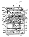
図1は、本実施形態に係る複写機500の概略構成図である。複写機500はプリンタ部100、これを載せる給紙装置200、プリンタ部100の上に固定されたスキャナ300などを備えている。また、このスキャナ300の上に固定された原稿自動搬送装置400なども備えている。
Hereinafter, as an image forming apparatus to which the present invention is applied, an embodiment of a tandem type color laser copier (hereinafter simply referred to as “copier 500”) in which a plurality of photoconductors are arranged in parallel will be described.
FIG. 1 is a schematic configuration diagram of a copying machine 500 according to the present embodiment. The copier 500 includes a
プリンタ部100は、イエロー(Y)、マゼンダ(M)、シアン(C)、黒(K)の各色の画像を形成するための4組のプロセスカートリッジ18Y,M,C,Kからなる画像形成ユニット20を備えている。各符号の数字の後に付されたY,M,C,Kは、イエロー、シアン、マゼンダ、ブラック用の部材であることを示している(以下同様)。プロセスカートリッジ18Y,M,C,Kの他には、光書込ユニット21、中間転写ユニット17、二次転写装置22、レジストローラ対49、ベルト定着方式の定着装置25などが配設されている。
The
光書込ユニット21は、図示しない光源、ポリゴンミラー、f−θレンズ、反射ミラーなどを有し、画像データに基づいて後述の感光体の表面にレーザ光を照射する。
プロセスカートリッジ18Y,M,C,Kは、ドラム状の感光体1、帯電器、現像装置4、ドラムクリーニング装置、除電器などを有している。
The optical writing unit 21 includes a light source (not shown), a polygon mirror, an f-θ lens, a reflection mirror, and the like, and irradiates the surface of a photoreceptor to be described later with laser light based on image data.
The process cartridges 18Y, 18M, 18C, and 18K include a drum-shaped photosensitive member 1, a charger, a developing
以下、イエロー用のプロセスカートリッジ18について説明する。
帯電手段たる帯電器によって、感光体1Yの表面は一様帯電される。帯電処理が施された感光体1Yの表面には、光書込ユニット21によって変調及び偏向されたレーザ光が照射される。これにより、照射部(露光部)の感光体1Yの表面の電位が減衰する。この表面の電位の減衰により、感光体1Y表面にY用の静電潜像が形成される。形成されたY用の静電潜像は現像手段たる現像装置4Yによって現像されてYトナー像となる。
Y用の感光体1Y上に形成されたYトナー像は、後述の中間転写ベルト110に一次転写される。一次転写後の感光体1Yの表面は、ドラムクリーニング装置によって転写残トナーがクリーニングされる。
Y用のプロセスカートリッジ18Yにおいて、ドラムクリーニング装置によってクリーニングされた感光体1Yは、除電器によって除電される。そして、帯電器によって一様帯電せしめられて、初期状態に戻る。以上のような一連のプロセスは、他のプロセスカートリッジ18M,C,Kについても同様である。
Hereinafter, the yellow process cartridge 18 will be described.
The surface of the photoreceptor 1Y is uniformly charged by a charger as charging means. The surface of the photoreceptor 1 </ b> Y that has been subjected to charging processing is irradiated with laser light that has been modulated and deflected by the optical writing unit 21. Thereby, the potential of the surface of the photoreceptor 1Y of the irradiation part (exposure part) is attenuated. Due to the attenuation of the surface potential, an electrostatic latent image for Y is formed on the surface of the photoreceptor 1Y. The formed electrostatic latent image for Y is developed by the developing device 4Y as developing means to become a Y toner image.
The Y toner image formed on the Y photoconductor 1Y is primarily transferred to an
In the Y process cartridge 18Y, the photoconductor 1Y cleaned by the drum cleaning device is discharged by the charge eliminator. Then, it is uniformly charged by the charger and returns to the initial state. The series of processes as described above is the same for the other process cartridges 18M, 18C, and 18K.
次に、中間転写ユニットについて説明する。
中間転写ユニット17は、中間転写ベルト110やベルトクリーニング装置90などを有している。また、張架ローラ14、駆動ローラ15、二次転写バックアップローラ16、4つの一次転写バイアスローラ62Y,M,C,Kなども有している。
中間転写ベルト110は、張架ローラ14を含む複数のローラによってテンション張架されている。そして、図示しないベルト駆動モータによって駆動される駆動ローラ15の回転によって図中時計回りに無端移動せしめられる。
4つの一次転写バイアスローラ62Y,M,C,Kは、それぞれ中間転写ベルト110の内周面側に接触するように配設され、図示しない電源から一次転写バイアスの印加を受ける。また、中間転写ベルト110をその内周面側から感光体1Y,M,C,Kに向けて押圧してそれぞれ一次転写ニップを形成する。各一次転写ニップには、一次転写バイアスの影響により、感光体1と一次転写バイアスローラ62との間に一次転写電界が形成される。
Y用の感光体1Y上に形成された上述のYトナー像は、この一次転写電界やニップ圧の影響によって中間転写ベルト110上に一次転写される。このYトナー像の上には、M,C,K用の感光体1M,C,K上に形成されたM,C,Kトナー像が順次重ね合わせて一次転写される。この重ね合わせの一次転写により、中間転写ベルト110上には多重トナー像たる4色重ね合わせトナー像(以下、4色トナー像という)が形成される。
中間転写ベルト110上に重ね合わせ転写された4色トナー像は、後述の二次転写ニップで図示しない記録体たる転写紙に二次転写される。二次転写ニップ通過後の中間転写ベルト110の表面に残留する転写残トナーは、図中左側の駆動ローラ15との間にベルトを挟み込むベルトクリーニング装置90によってクリーニングされる。
Next, the intermediate transfer unit will be described.
The intermediate transfer unit 17 includes an
The
The four primary transfer bias rollers 62Y, 62M, 62C, and 62K are disposed so as to be in contact with the inner peripheral surface side of the
The above-described Y toner image formed on the Y photoconductor 1Y is primarily transferred onto the
The four-color toner image superimposed and transferred onto the
次に、二次転写装置22について説明する。
中間転写ユニット17の図中下方には、2本の張架ローラ23によって紙搬送ベルト24を張架している二次転写装置22が配設されている。紙搬送ベルト24は、少なくとも何れか一方の張架ローラ23の回転駆動に伴って、図中反時計回りに無端移動せしめられる。2本の張架ローラ23のうち、図中右側に配設された一方のローラは、中間転写ユニット17の二次転写バックアップローラ16との間に、中間転写ベルト110及び紙搬送ベルト24を挟み込んでいる。この挟み込みにより、中間転写ユニット17の中間転写ベルト110と、二次転写装置22の紙搬送ベルト24とが接触する二次転写ニップが形成されている。そして、この一方の張架ローラ23には、トナーと逆極性の二次転写バイアスが図示しない電源によって印加される。この二次転写バイアスの印加により、二次転写ニップには中間転写ユニット17の中間転写ベルト110上の4色トナー像をベルト側からこの一方の張架ローラ23側に向けて静電移動させる二次転写電界が形成される。後述のレジストローラ対49によって中間転写ベルト110上の4色トナー像に同期するように二次転写ニップに送り込まれた転写紙には、この二次転写電界やニップ圧の影響を受けた4色トナー像が二次転写せしめられる。なお、このように一方の張架ローラ23に二次転写バイアスを印加する二次転写方式に代えて、転写紙を非接触でチャージさせるチャージャを設けてもよい。
Next, the secondary transfer device 22 will be described.
Below the intermediate transfer unit 17 in the figure, a secondary transfer device 22 is disposed in which a paper conveying belt 24 is stretched by two stretching rollers 23. The paper transport belt 24 is moved endlessly in the counterclockwise direction in the drawing in accordance with the rotational drive of at least one of the stretching rollers 23. One of the two stretching rollers 23 arranged on the right side in the drawing sandwiches the
複写機500本体の下部に設けられた給紙装置200には、内部に複数の転写紙を紙束の状態で複数枚重ねて収容可能な給紙カセット44が、鉛直方向に複数重なるように配設されている。それぞれの給紙カセット44は、紙束の一番上の転写紙に給紙ローラ42を押し当てている。そして、給紙ローラ42を回転させることにより、一番上の転写紙を給紙路46に向けて送り出される。
In the
給紙カセット44から送り出された転写紙を受け入れる給紙路46は、複数の搬送ローラ対47と、給紙路46内の末端付近に設けられたレジストローラ対49とを有している。そして、転写紙をレジストローラ対49に向けて搬送する。レジストローラ対49に向けて搬送された転写紙は、レジストローラ対49のローラ間に挟まれる。一方、中間転写ユニット17において、中間転写ベルト110上に形成された4色トナー像は、ベルトの無端移動に伴って二次転写ニップに進入する。レジストローラ対49は、ローラ間に挟み込んだ転写紙を二次転写ニップにて4色トナー像に密着させ得るタイミングで送り出す。これにより、二次転写ニップでは、中間転写ベルト110上の4色トナー像が転写紙に密着する。そして、転写紙上に二次転写されて、白色の転写紙上でフルカラー画像となる。このようにしてフルカラー画像が形成された転写紙は、紙搬送ベルト24の無端移動に伴って二次転写ニップを出た後、紙搬送ベルト24上から定着装置25に送られる。
The
定着装置25は、定着ベルト26を2本のローラによって張架しながら無端移動せしめるベルトユニットと、このベルトユニットの一方のローラに向けて押圧される加圧ローラ27とを備えている。これら定着ベルト26と加圧ローラ27とは互いに当接して定着ニップを形成しており、紙搬送ベルト24から受け取った転写紙をここに挟み込む。ベルトユニットにおける2本のローラのうち、加圧ローラ27から押圧される方のローラは、内部に図示しない熱源を有しており、これの発熱によって定着ベルト26を加熱する。加熱された定着ベルト26は、定着ニップに挟み込まれた転写紙を加熱する。この加熱やニップ圧の影響により、フルカラー画像が転写紙に定着せしめられる。 The fixing device 25 includes a belt unit that moves the fixing belt 26 endlessly while being stretched by two rollers, and a pressure roller 27 that is pressed toward one roller of the belt unit. The fixing belt 26 and the pressure roller 27 are in contact with each other to form a fixing nip, and the transfer paper received from the paper transport belt 24 is sandwiched therebetween. Of the two rollers in the belt unit, the roller that is pressed from the pressure roller 27 has a heat source (not shown) inside, and heats the fixing belt 26 by the generated heat. The heated fixing belt 26 heats the transfer paper sandwiched in the fixing nip. The full color image is fixed on the transfer paper by the influence of the heating and the nip pressure.
定着装置25内で定着処理が施された転写紙は、プリンタ筐体の図中左側板の外側に設けたスタック部57上にスタックされるか、もう一方の面にもトナー像を形成するために上述の二次転写ニップに戻されるかする。 The transfer paper subjected to the fixing process in the fixing device 25 is stacked on the stack portion 57 provided outside the left side plate in the drawing of the printer housing, or forms a toner image on the other surface. To the secondary transfer nip described above.
図示しない原稿のコピーがとられる際には、例えばシート原稿の束が原稿自動搬送装置400の原稿台30の上にセットされる。但し、その原稿が本状に閉じられている片綴じ原稿である場合には、コンタクトガラス32上にセットされる。このセットに先立ち、複写機500本体に対して原稿自動搬送装置400が開かれ、スキャナ300のコンタクトガラス32が露出される。この後、閉じられた原稿自動搬送装置400によって片綴じ原稿が押さえられる。
When a document (not shown) is copied, for example, a bundle of sheet documents is set on the document table 30 of the
このようにして原稿がセットされた後、図示しないコピースタートスイッチが押下されると、スキャナ300による原稿読取動作がスタートする。但し、原稿自動搬送装置400にシート原稿がセットされた場合には、この原稿読取動作に先立って、原稿自動搬送装置400がシート原稿をコンタクトガラス32まで自動移動させる。原稿読取動作では、まず、第1走行体33と第2走行体34とがともに走行を開始し、第1走行体33に設けられた光源から光が発射される。そして、原稿面からの反射光が第2走行体34内に設けられたミラーによって反射せしめられ、結像レンズ35を通過した後、読取センサ36に入射される。読取センサ36は、入射光に基づいて画像情報を構築する。
When a copy start switch (not shown) is pressed after the document is set in this way, the document reading operation by the
このような原稿読取動作と並行して、各プロセスカートリッジ18Y,M,C,K内の各機器や、中間転写ユニット17、二次転写装置22、定着装置25がそれぞれ駆動を開始する。そして、読取センサ36によって構築された画像情報に基づいて、光書込ユニット21が駆動制御されて、各感光体1Y,M,C,K上に、Y,M,C,Kトナー像が形成される。これらトナー像は、中間転写ベルト110上に重ね合わせ転写された4色トナー像となる。
In parallel with such a document reading operation, each device in each of the process cartridges 18Y, 18M, 18C, 18K, the intermediate transfer unit 17, the secondary transfer device 22, and the fixing device 25 starts driving. Based on the image information constructed by the reading sensor 36, the optical writing unit 21 is driven and controlled, and Y, M, C, and K toner images are formed on the respective photoreceptors 1Y, 1M, 1C, and 1K. Is done. These toner images become four-color toner images superimposed and transferred on the
また、原稿読取動作の開始とほぼ同時に、給紙装置200内では給紙動作が開始される。この給紙動作では、給紙ローラ42の1つが選択回転せしめられ、ペーパーバンク43内に多段に収容される給紙カセット44の1つから転写紙が送り出される。送り出された転写紙は、分離ローラ45で1枚ずつ分離されて反転給紙路46に進入した後、搬送ローラ対47によって二次転写ニップに向けて搬送される。このような給紙カセット44からの給紙に代えて、手差しトレイ51からの給紙が行われる場合もある。この場合、手差し給紙ローラ50が選択回転せしめられて手差しトレイ51上の転写紙を送り出した後、分離ローラ52が転写紙を1枚ずつ分離してプリンタ部100の手差し給紙路53に給紙する。
Further, almost simultaneously with the start of the document reading operation, the paper feeding operation is started in the
複写機500は、2色以上のトナーからなる多色画像を形成する場合には、中間転写ベルト110をその上部張架面がほぼ水平になる姿勢で張架して、上部張架面に全ての感光体1Y,M,C,Kを接触させる。これに対し、Kトナーのみからなるモノクロ画像を形成する場合には、図示しない機構により、中間転写ベルト110を図中左下に傾けるような姿勢にして、その上部張架面をY,M,C用の感光体1Y,M,Cから離間させる。そして、4つの感光体1Y,M,C,Kのうち、K用の感光体1Kだけを図中反時計回りに回転させて、Kトナー像だけを作像する。この際、Y,M,Cについては、感光体1だけでなく、現像装置4も駆動を停止させて、感光体1や現像装置4の各部材及び現像装置4内の現像剤の不要な消耗を防止する。
When the copier 500 forms a multicolor image composed of toners of two or more colors, the
複写機500は、複写機500内の各機器の制御を司るCPU等から構成される図示しない制御部と、液晶ディスプレイや各種キーボタン等などから構成される図示しない操作表示部とを備えている。操作者は、この操作表示部に対するキー入力操作により、制御部に対して命令を送ることで、転写紙の片面だけに画像を形成するモードである片面プリントモードについて、3つのモードの中から1つを選択することができる。この3つの片面プリントモードとは、ダイレクト排出モードと、反転排出モードと、反転デカール排出モードとからなる。 The copier 500 includes a control unit (not shown) composed of a CPU and the like that controls each device in the copier 500, and an operation display unit (not shown) composed of a liquid crystal display, various key buttons, and the like. . The operator sends a command to the control unit by a key input operation on the operation display unit, so that one of the three modes is selected from the three-sided print mode, which is a mode for forming an image only on one side of the transfer paper. You can choose one. The three single-sided printing modes include a direct discharge mode, a reverse discharge mode, and a reverse decal discharge mode.
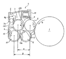
図2は、4つプロセスカートリッジ18Y,M,C,Kのうちの1つが備える現像装置4及び感光体1を示す拡大構成図である。4つのプロセスカートリッジ18Y,M,C,Kは、それぞれ扱うトナーの色が異なる点以外はほぼ同様の構成になっているので、同図では「4」に付すY,M,C,Kという添字を省略している。
図2に示すように感光体1は図中矢印G方向に回転しながら、その表面を不図示の帯電装置により帯電される。帯電された感光体1の表面は不図示の露光装置より照射されたレーザ光により静電潜像を形成された潜像に現像装置4からトナーを供給され、トナー像を形成する。
FIG. 2 is an enlarged configuration diagram illustrating the developing
As shown in FIG. 2, the surface of the photosensitive member 1 is charged by a charging device (not shown) while rotating in the direction of arrow G in the drawing. The charged surface of the photoreceptor 1 is supplied with toner from the developing
現像装置4は、図中矢印I方向に表面移動しながら感光体1の表面の潜像にトナーを供給し、現像する現像剤担持体としての現像ローラ5を有している。現像ローラ5は回転可能な現像スリーブを備え、その内部に複数の磁極からなる不図示の磁性体が配置されている。磁性体は現像ローラ5の表面上で現像剤を保持するために必要である。
また、現像ローラ5に現像剤を供給しながら現像ローラ5の軸線方向に沿って図2の手前方向に現像剤を搬送する供給搬送部材としての供給スクリュ8を有している。
現像ローラ5の供給スクリュ8との対向部から表面移動方向下流側には、現像ローラ5に供給された現像剤を現像に適した厚さに規制する現像剤規制手段としてのドクタブレード12を備えている。
現像ローラ5の感光体1との対向部である現像領域よりも表面移動方向下流側では、現像領域を通過し、現像ローラ5の表面から離脱した現像済みの現像剤を回収する回収搬送路7が現像ローラ5と対向する。回収搬送路7は、回収した回収現像剤を現像ローラ5の軸線方向に沿って供給スクリュ8と同方向に搬送する回収搬送部材として、軸線方向に平行に配置されたらせん状の回収スクリュ6を備えている。供給スクリュ8を備えた供給搬送路9は現像ローラ5の横方向に、回収スクリュ6を備えた回収搬送路7は現像ローラ5の下方に並設されている。
なお、現像ローラ5からの現像剤の離脱は、先に述べた現像スリーブ内部にある磁性体を、離脱させたい箇所のみ磁極がない状態に設定することにより、現像剤の分離・離脱を可能としている。また、離脱させたい箇所に反発磁界が形成されるような磁極配置の磁性体を用いてもよい。
The developing
Further, a
A
A
The developer can be separated from the developing
現像装置4は、供給搬送路9の下方で回収搬送路7に並列して攪拌搬送路10を設けている。攪拌搬送路10は、現像ローラ5の軸線方向に沿って現像剤を攪拌しながら供給スクリュ8とは逆方向である図中奥側に搬送する攪拌搬送部材として、軸線方向に平行に配置された、らせん状の攪拌スクリュ11を備えている。
The developing
供給搬送路9と攪拌搬送路10とは仕切り壁としての第一仕切り壁133によって仕切られている。第一仕切り壁133の供給搬送路9と攪拌搬送路10とを仕切る箇所は図中手前側と奥側との両端は開口部となっており、供給搬送路9と攪拌搬送路10とが連通している。
なお、供給搬送路9と回収搬送路7とも第一仕切り壁133によって仕切られているが、第一仕切り壁133の供給搬送路9と回収搬送路7とを仕切る箇所には開口部を設けていない。
また、攪拌搬送路10と回収搬送路7との2つの現像剤搬送路は仕切り部材としての第二仕切り壁134によって仕切られている。第二仕切り壁134は、図中手前側が開口部となっており、攪拌搬送路10と回収搬送路7とが連通している。
現像剤搬送部材である供給スクリュ8、回収スクリュ6及び攪拌スクリュ11は樹脂もしくは金属のスクリュからなっており各スクリュ径は全てφ22[mm]でスクリュピッチは供給スクリュが50[mm]の2条巻き、回収スクリュ6及び攪拌スクリュ11が25[mm]の1条巻き、回転数は全て約600[rpm]に設定している。
The
The
In addition, the two developer conveyance paths of the
The
現像ローラ5上にステンレスからなるドクタブレード12によって薄層化された現像剤を感光体1との対抗部である現像領域まで搬送し現像を行う。現像ローラ5の表面はV溝あるいはサンドブラスト処理されておりφ25[mm]のAlもしくはSUS素管からなり、ドクタブレード12及び感光体1とのギャップは0.3[mm]程度となっている。
現像後の現像剤は回収搬送路7にて回収を行い、図2中の断面手前側に搬送され、非画像領域部に設けられた第一仕切り壁133の開口部で、攪拌搬送路10へ現像剤が移送される。なお、攪拌搬送路10における現像剤搬送方向上流側の第一仕切り壁133の開口部の付近で攪拌搬送路10の上側に設けられた、後述するトナー補給口95から攪拌搬送路10にトナーが供給される。
The developer thinned by the
The developer after the development is collected in the
次に、3つの現像剤搬送路内での現像剤の循環について説明する。
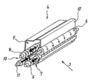
図3は現像剤搬送路内の現像剤の流れを説明する現像装置4の斜視断面図である。図中の各矢印は現像剤の移動方向を示している。
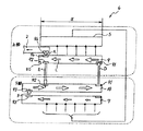
また、図4は、現像装置4内の現像剤の流れの模式図であり、図3と同様、図中の各矢印は現像剤の移動方向を示している。
Next, the circulation of the developer in the three developer conveyance paths will be described.
FIG. 3 is a perspective sectional view of the developing
4 is a schematic diagram of the flow of the developer in the developing
攪拌搬送路10から現像剤の供給を受けた供給搬送路9では、現像ローラ5に現像剤を供給しながら、供給スクリュ8の搬送方向下流側に現像剤を搬送する。そして、現像ローラ5に供給され現像に用いられず供給搬送路9の搬送方向下流端まで搬送された余剰現像剤は第一仕切り壁133の余剰開口部92より攪拌搬送路10に供給される(図4中矢印E)。
一方、現像ローラ5に供給された現像剤は現像領域で現像に用いられた後、現像ローラ5から分離・離脱して、回収搬送路7に受け渡される。現像ローラ5から回収搬送路7に受け渡され、回収スクリュ6によって回収搬送路7の搬送方向下流端まで搬送された回収現像剤は第二仕切り壁134の回収開口部93より攪拌搬送路10に供給される(図4中矢印F)。
そして、攪拌搬送路10は、供給された余剰現像剤と回収現像剤とを攪拌し、攪拌スクリュ11の搬送方向下流側であり、供給スクリュ8の搬送方向上流側に搬送し、第一仕切り壁133の供給開口部91より供給搬送路9に供給される(図4中矢印D)。
攪拌搬送路10では攪拌スクリュ11によって、回収現像剤、余剰現像剤及び移送部で必要に応じて補給されるトナーを、回収搬送路7及び供給搬送路9の現像剤と逆方向に攪拌搬送する。そして、搬送方向下流側で供給開口部91によって連通している供給搬送路9の搬送方向上流側に攪拌された現像剤を移送する。なお、攪拌搬送路10の下方には、不図示の透磁率センサからなるトナー濃度センサが設けられ、センサ出力により不図示のトナー補給制御装置を作動し、不図示のトナー収容部からトナー補給を行っている。
In the
On the other hand, the developer supplied to the developing
The agitating and conveying
In the agitating and conveying
図4に示す現像装置4では、供給搬送路9と回収搬送路7とを備え、現像剤の供給と回収とを異なる現像剤搬送路で行うので、現像済みの現像剤が供給搬送路9に混入することがない。このため、供給搬送路9の搬送方向下流側ほど現像ローラ5に供給される現像剤のトナー濃度が低下することを防止することができる。また、回収搬送路7と攪拌搬送路10とを備え、現像剤の回収と攪拌とを異なる現像剤搬送路で行うので、現像済みの現像剤が攪拌の途中に落ちることがない。これにより、十分に攪拌がなされた現像剤が供給搬送路9に供給されるため、供給搬送路9に供給されるの現像剤が攪拌不足となることを防止することができる。このように、供給搬送路9内の現像剤のトナー濃度が低下することを防止し、供給搬送路9内の現像剤が攪拌不足となることを防止することができるので現像時の画像濃度を一定にすることができる。
In the developing
なお、図4に示すように、現像装置4の下部から上部への現像剤の移動は矢印Dのみである。矢印Dで示す現像剤の移動は、攪拌スクリュ11の回転で攪拌搬送路10の下流側に現像剤を押し込むことによって、現像剤を盛り上がらせて供給搬送路9に現像剤を供給するものである。
このような現像剤の移動は、現像剤に対してストレスを与えることになり、現像剤の寿命低下の一因となる。
このような、現像剤を下方から上方に持ち上げる際に現像剤にストレスがかかり現像剤中のキャリアの膜削れやトナーのスペント化がその個所で発生し、それに伴い画像品質の安定性が保たれなくなってしまう。
よって、矢印Dで示す現像剤の移動における現像剤のストレスを軽減することで現像剤の長寿命化を図ることが出来る。現像剤の長寿命化を図ることにより、現像剤の劣化を防止して常に画像濃度ムラの無い画像品質の安定した現像装置を提供することができる。
As shown in FIG. 4, the developer moves from the lower part to the upper part of the developing
Such movement of the developer gives stress to the developer and contributes to a decrease in the life of the developer.
When the developer is lifted from the bottom to the top, stress is applied to the developer, and the carrier film in the developer is scraped off and the toner is spent on the spot. Accordingly, the stability of the image quality is maintained. It will disappear.
Therefore, the life of the developer can be extended by reducing the stress of the developer in the movement of the developer indicated by the arrow D. By prolonging the life of the developer, it is possible to provide a developing device that prevents deterioration of the developer and is always stable in image quality without image density unevenness.
本実施形態の現像装置4では、図2に示すように、供給搬送路9を攪拌搬送路10の斜め上方になるように配置している。斜め上方に配置することにより、供給搬送路9を攪拌搬送路10の垂直上方に設け現像剤を持ち上げるものに比べて、矢印Dで示す現像剤の移動における現像剤のストレスを軽減することができる。
さらに、現像装置4では、供給搬送路9と攪拌搬送路10とを斜めに配置することで、図2に示すように、攪拌搬送路10の上部壁面が供給搬送路9の下部壁面よりも高い位置となるように配置している。
供給搬送路9を攪拌搬送路10に対して垂直上方に持ち上げることは、重力に逆らって現像剤を攪拌スクリュ11の圧によって持ち上げるので現像剤にストレスがかかる。一方、攪拌搬送路10の上部壁面が供給搬送路9の下部壁面よりも高い位置となるように配置することで、攪拌搬送路10の最高点に存在する現像剤が供給搬送路9の最下点に重力に逆らわず流れ込むことができるので、現像剤にかかるストレスを低減することができる。
なお、攪拌搬送路10の現像剤搬送路下流側の、攪拌搬送路10と供給搬送路9とが連通している部分の攪拌スクリュ11の軸にフィン部材を設けても良い。このフィン部材は攪拌スクリュ11の軸方向に平行な辺と、攪拌スクリュの軸方向に直交する辺とから構成される板状の部材である。このフィン部材で現像剤を掻き上げることにより、攪拌搬送路10から供給搬送路9へ、より効率的な現像剤の受渡しを行うことができる。
In the developing
Further, in the developing
Lifting the
Note that a fin member may be provided on the shaft of the stirring
また、現像装置4では、現像ローラ5と供給搬送路9との中心間距離Aが、現像ローラ5と攪拌搬送路10との中心間距離Bよりも短くなるように、供給搬送路9と攪拌搬送路10とを配置している。これにより供給搬送路9から現像ローラ5に現像剤を無理無く供給することができ、装置の小型化を図ることもできる。
また、攪拌スクリュ11は、図2中の手前側から見て反時計回り方向(図中矢印C方向)に回転しており、現像剤は攪拌スクリュ11の形状に沿って現像剤を持ち上げて供給搬送路9に移送させている。これにより、現像剤を効率良く持ち上げることが可能となり現像剤にかかるストレスもより低減することができる。
Further, in the developing
Further, the stirring
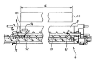
図5は、現像装置4の供給スクリュ8の回転中心における断面を図3中の矢印J方向から見た断面説明図である。図中Hは、現像剤担持体である現像ローラ5が、潜像担持体である感光体1にトナーを供給する現像領域を示している。この現像領域Hの現像ローラ5の回転軸の軸線方向の幅が現像領域幅αである。
図5に示すように、現像装置4は攪拌搬送路10から供給搬送路9に現像剤を持ち上げる箇所である供給開口部91と、供給搬送路9から攪拌搬送路10に現像剤を落下させる余剰開口部92とがともに現像領域幅α内に設けられている。
FIG. 5 is a cross-sectional explanatory view of the cross section at the rotation center of the
As shown in FIG. 5, the developing
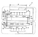
図6は、図4とは異なる構成の現像装置4内の現像剤の流れの模式図である。
図6に示す現像装置4は、供給開口部91と余剰開口部92とを現像領域幅αの外側に設けている。供給開口部91を現像領域幅αの外側に設けているため、供給搬送路9の搬送方向上流側は現像ローラ5よりも供給搬送路上流側領域β分長くなっている。また、余剰開口部92を現像領域幅αの外側に設けているため、供給搬送路9の搬送方向下流側は現像ローラ5よりも供給搬送路下流側領域γ分長くなっている。
FIG. 6 is a schematic diagram of the developer flow in the developing
The developing
一方、図4に示す構成の現像装置4では、供給開口部91を現像領域幅α内に設けているため、供給搬送路9の搬送方向上流側は図6の現像装置4よりも供給搬送路上流側領域β分短くすることができる。また、余剰開口部92を現像領域幅α内に設けているため、供給搬送路9の搬送方向下流側は図6の現像装置4よりも供給搬送路下流側領域γ分短くすることができる。
このように、図4の現像装置4は供給開口部91と余剰開口部92とを現像領域幅α内に設けているため、図6に示す現像装置4に比べて、現像装置4の上部の省スペース化を図ることが出来る。
On the other hand, in the developing
4 is provided with the
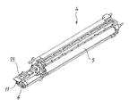
次に、現像装置4の供給搬送路9、攪拌搬送路10及び回収搬送路7からなる現像剤搬送路へのトナーを補給する位置について説明する。図7は、現像装置4の外観斜視図である。
図7に示すように、トナーを補給するトナー補給口95を、攪拌スクリュ11を備える攪拌搬送路10の搬送方向上流端部の上方に設けている。このトナー補給口95は現像ローラ5の幅方向端部よりも外側に設けてあるので、現像領域幅αよりも外側となっている。
この、トナー補給口95を設けた箇所は供給搬送路9の搬送方向の延長線上であり、図6における供給搬送路下流側領域γの空いたスペースに該当する。余剰開口部92を現像領域幅α内に設けることで空いたスペースにトナー補給口95を設けることにより、現像装置4の小型化を図ることが出来る。
また、トナー補給口95としては、攪拌搬送路10の搬送方向上流端部の上方に限らず、回収搬送路7の下流端部の上方に設けても良い。
さらに、回収搬送路7から攪拌搬送路10へ現像剤の受渡しを行う箇所である回収開口部93の真上にトナー補給口95を設けるようにしても良い。回収開口部93の真上のスペースも余剰開口部92を現像領域幅α内に設けることで空いたスペースであるので、この位置にトナー補給口95を設けることにより、現像装置4の小型化を図ることができる。さらに、受渡し部である回収開口部93では現像剤が混ざりやすいため、この位置で補給を行うことによってより効率よく現像剤の攪拌を行うことができる。
Next, the position at which toner is supplied to the developer conveyance path including the
As shown in FIG. 7, a
The portion where the
Further, the
Further, a
図4を用いて説明した現像装置4のように、攪拌搬送路10の搬送方向下流端から供給搬送路9の搬送方向上流端に現像剤を受け渡す供給開口部91と、供給搬送路9の下流端から攪拌搬送路10の搬送方向上流端に現像剤を受け渡す余剰開口部92とを現像領域幅α内に設けているため、従来の現像装置4に比べて、現像装置4の上部の省スペース化を図ることが出来、現像装置4全体の省スペース化を図ることが出来る。
また、余剰開口部92を現像領域幅α内に設けることで空いたスペースにトナー補給口95を設けることにより、現像装置4の小型化を図ることが出来る。
また、回収搬送路7から攪拌搬送路10への現像剤の受渡し部である回収開口部93の上方からトナー補給を行うことによってより効率よく現像剤の攪拌を行うことができる。
また、画像形成装置としての複写機500のプリンタ部100の現像手段として、現像装置4を備えることにより、装置全体の省スペース化を図ることが出来る。
As in the developing
Also, by providing the
Further, the developer can be more efficiently stirred by replenishing the toner from above the
Further, by providing the developing
現像剤補給手段である不図示のトナー補給制御装置は、不図示のトナー収容部内のトナーをトナー補給口95から現像装置4に補給する。本実施形態の現像装置4では現像装置4のトナー補給口95からトナーとキャリアとを含む現像剤が補給される。以降、現像装置4に補給されるトナーとキャリアとが混合された現像剤をプレミックストナーと称する。
A toner replenishment control device (not shown) that is a developer replenishing unit replenishes toner in a toner storage unit (not shown) to the developing
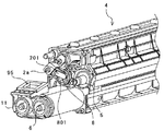
図8は、現像装置4から、排出搬送部材である排出スクリュ2a、攪拌スクリュ11、回収スクリュ6、及び、ドクタブレード12を取り外した状態の手前側端部近傍の斜視説明図である。
本実施形態の現像装置4では、供給搬送路9の搬送方向下流端に到達した余剰現像剤を供給搬送路9の搬送方向上流端に搬送する循環搬送路は攪拌搬送路10である。また、循環搬送路である攪拌搬送路10内の現像剤に対して搬送力を付与する循環搬送部材は攪拌スクリュ11である。さらに、供給搬送路9の搬送方向下流端近傍に設けられ、通過した現像剤が循環搬送路である攪拌搬送路10に受け渡される循環開口部は余剰開口部92である。また、現像装置4は、通過した現像剤が現像装置4の装置外に排出される現像剤排出手段としての現像剤排出口94を供給搬送路9に備える。現像剤排出口94を通過した現像剤は排出現像剤として排出搬送路2に受け渡され、排出スクリュ2aが回転することによって供給搬送路9の搬送方向(図2及び図8中の手前側に向かう方向)とは逆方向(図2及び図8中の奥側に向かう方向)に搬送される。
排出搬送路2は、供給搬送路9の搬送方向下流側で排出仕切り壁135を挟んで供給搬送路9と隣り合うように配置され、現像剤排出口94は供給搬送路9と排出搬送路2とを連通するように排出仕切り壁135に設けられた開口である。
FIG. 8 is an explanatory perspective view of the vicinity of the front end of the developing
In the developing
The discharge conveyance path 2 is disposed on the downstream side in the conveyance direction of the
また、現像装置4は、供給搬送路9の搬送方向下流端近傍に到達し、循環開口部である余剰開口部92に入らなかった現像剤を余剰開口部92の近傍で滞留させる現像剤滞留手段としての供給下流端壁面80を備えている。さらに、排出開口部である現像剤排出口94は、余剰開口部92よりも上方で、且つ、供給下流端壁面80によって滞留した滞留現像剤のうち、現像剤排出口94の位置に達した現像剤を通過させるように設けられている。言い換えると、供給搬送路9の搬送方向下流端近傍に到達した現像剤で、余剰開口部92に入ることができず、余剰開口部92から溢れ出た余剰現像剤が供給下流端壁面80によって塞き止められ滞留現像剤となる。そして、この滞留現像剤の嵩が増加したときに、余剰開口部92よりも上方に設けられた現像剤排出口94に到達した現像剤が現像剤排出口94を通って排出搬送路2に排出される。
Further, the developing
図9は、排出搬送路2を通って現像装置4の現像ケーシングの外部に搬送された排出現像剤を受入れ、排出現像剤を排出現像剤収容部である排出現像剤タンク600まで搬送する排出搬送路である排出現像剤移送パイプ601の説明図である。
各現像装置4(Y,M,C,K)内の供給搬送路9から現像剤排出口94を通って各排出搬送路2(Y,M,C,K)よって現像剤排出口94とは逆側の現像装置4の端部まで搬送して現像装置4の現像ケーシングの外に排出現像剤を排出する。
各排出搬送路2(Y,M,C,K)の搬送方向下流端まで搬送され、現像装置4のケーシングから排出された現像剤は現像剤受入れ口604(Y,M,C,K)から排出現像剤移送パイプ601へ入る。排出現像剤移送パイプ601は排出現像剤移送パイプ601内の排出現像剤に搬送力を付与する排出収容搬送部材である排出収容スクリュ602を備える。排出現像剤移送パイプ601の一端には排出収容スクリュ駆動源603を備え、排出収容スクリュ602の回転によって、排出現像剤移送パイプ601内の現像剤は順次移送され、現像装置4の外部の排出現像剤収容部である排出現像剤タンク600に収容される。
なお、図9では、各排出搬送路2(Y,M,C,K)によって搬送された排出現像剤を一つの排出現像剤タンク600に搬送する構成を示しているが、各排出搬送路2(Y,M,C,K)のそれぞれに対応した各色の排出現像剤タンク600を個別に設けても良い。
FIG. 9 shows a discharge conveyance for receiving the discharged developer conveyed to the outside of the developing casing of the developing
What is the
The developer transported to the downstream end in the transport direction of each discharge transport path 2 (Y, M, C, K) and discharged from the casing of the developing
Although FIG. 9 shows a configuration in which the discharged developer conveyed by each discharge conveyance path 2 (Y, M, C, K) is conveyed to one
現像剤排出口94から排出搬送路2に排出された排出現像剤に含まれるキャリアは劣化した状態となっており、流動性が悪く、排出搬送路2の中で固着しやすい。また、排出現像剤は高温高湿の環境下では特に流動性が悪くなり、さらに固着しやすい状態となる。
また、排出スクリュ2aが一定の回転数で回転し続ける状態では、排出搬送路2内の排出現像剤に対して加えられる力の変動が生じない。このため、排出スクリュ2aが一定の回転数で回転している状態で、静止することが出来る箇所に位置する排出現像剤はその箇所から動くことなく凝集して、排出搬送路2内で固着するおそれがある。排出スクリュ2aが一定の回転数で回転している状態で、静止することが出来る箇所に位置する排出現像剤としては、排出スクリュ2aの軸部や羽部に付着し、排出スクリュ2aと共に連れまわる排出現像剤がある。排出スクリュ2aに付着して排出スクリュ2aと共に連れまわる排出現像剤は、排出スクリュ2aが回転しても搬送力の付与がなされず、排出スクリュ2aに付着した状態で静止する。
The carrier contained in the discharged developer discharged from the
Further, in a state where the
次に、本実施形態の特徴部について説明する。
本実施形態の現像装置4は、画像形成動作を行っている間は、現像剤搬送部材である供給スクリュ8、回収スクリュ6及び攪拌スクリュ11、そして、現像剤担持体である現像ローラ5は連続的に回転している。一方、排出スクリュ2aは間欠的に回転する。
Next, the characteristic part of this embodiment is demonstrated.
During the image forming operation of the developing
本実施形態の現像装置4では、排出スクリュ2aを間欠駆動させることによって、排出搬送路2内の排出現像剤に対して間欠的に衝撃を与えることが出来る。排出スクリュ2aが回転することよって搬送力が付与される箇所に位置する排出現像剤は、排出スクリュ2aが間欠駆動を行うことによって、加速と停止とを繰り返すため、加速時となるタイミングで間欠的に衝撃を受ける。これにより、微振動が発生し、排出スクリュ2aに付着した現像剤が凝集することを防止し、さらに、凝集した現像剤の凝集をほぐすことが出来る。
In the developing
このように、排出スクリュ2aを間欠的に駆動して、排出スクリュ2aによる排出現像剤への搬送力の付与を間欠的に行うことにより、排出搬送路2中の排出現像剤に対して間欠的に衝撃を与えることができる。そして、排出搬送路2内の排出スクリュ2aの搬送力が及ばない箇所の排出現像剤にも動きが生じ、排出現像剤の凝集をほぐすことが出来る。
これにより、凝集した排出現像剤が排出搬送路2内で固着することを防止することができ、排出現像剤を現像装置4外に良好に搬送することができる。
また、本実施形態の現像装置4では、排出搬送路2は排出現像剤を水平方向に搬送する構成である。排出現像剤を水平方向、または、上昇方向に搬送する場合、特に排出現像剤の詰まりが発生しやすくなるが、排出スクリュ2aを間欠駆動することによって、排出現像剤を水平方向に搬送する現像装置4であっても排出現像剤の詰まりの発生を防止することが出来る。
また、画像形成のランニングコストを考えるとプレミックストナーに含まれるキャリアの量を少量であることが望ましい。プレミックストナーに含まれるキャリアの量を少量とすると、現像剤排出口94から排出される現像剤量も少量となり、現像装置4内のキャリアの入れ替わりが少なくなり、排出される現像剤に含まれるキャリアは、より劣化したものとなる。より劣化したキャリアは排出搬送路2での固着の危険性は高まるが、本実施形態の現像装置4のように、排出スクリュ2aを間欠駆動することによって、排出現像剤の固着を防止し、排出搬送路2の詰まりの発生を防止することが出来る。
As described above, the
Thereby, it is possible to prevent the agglomerated discharged developer from adhering in the discharge conveyance path 2 and to convey the discharged developer to the outside of the developing
Further, in the developing
Considering the running cost of image formation, it is desirable that the amount of carrier contained in the premix toner is small. If the amount of the carrier contained in the premix toner is small, the amount of the developer discharged from the
また、図2及び図8に示すように、排出搬送路2の搬送方向上流側端部の近傍に設けられている。この位置では、排出搬送部材である排出スクリュ2aの搬送方向上流側の端部近傍は、現像剤排出手段である現像剤排出口94と対向している。このため、排出スクリュ2aが常時高速回転している場合は、排出スクリュ2aが現像剤を跳ね上げてしまい、排出搬送路2内の現像剤が現像剤排出口94から逆流して滞留してしまう場合があった。
このような問題に対して、本実施形態の現像装置4であれば、間欠駆動によって排出スクリュ2aが間欠回転であるので、排出スクリュ2aが現像剤を跳ね上げてしまい、現像剤が現像剤排出口94から逆流して滞留してしまうことを抑制することができる。
Further, as shown in FIGS. 2 and 8, it is provided in the vicinity of the upstream end portion in the transport direction of the discharge transport path 2. At this position, the vicinity of the upstream end of the
With respect to such a problem, in the developing
〔実施例〕
次に、排出スクリュ2aを間欠的に回転させる実施例について説明する。
図10は、実施例の現像装置4の排出搬送路2の搬送方向上流側の拡大斜視図である。
図10に示すように、供給スクリュ8の現像装置4のケーシングの軸方向外側には供給スクリュ8と同軸で、供給スクリュ8の駆動源から駆動が伝達されて、供給スクリュ8とともに連続的に回転駆動する偏心カム801を備えている。また、偏心カム801が回転運動することによって、排出スクリュ2aの回転軸を揺動中心として揺動する揺動レバー201を備える。
( Example )
Next, an embodiment in which the
Figure 10 is an enlarged perspective view of the upstream side of the discharge conveyance path 2 of the developing
As shown in FIG. 10, the
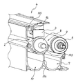
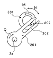
図11は、偏心カム801と揺動レバー201との拡大模式図である。
図11に示すように、偏心カム801は、供給スクリュ8の回転軸とに対して偏心した位置に突起部802を備えている。また、揺動レバー201は突起部802と嵌合するように溝部202を備えている。そして、供給スクリュ8が回転駆動して、偏心カム801が矢印M方向に回転すると、揺動レバー201は排出スクリュ2aの回転軸を中心にして矢印Nで示すように揺動する。
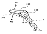
図12は、揺動レバー201と排出スクリュ2aとの接続の斜視説明図である。
図12に示すように、揺動レバー201はワンウェイクラッチ203を介して排出スクリュ2aの回転軸に接続している。そして、ワンウェイクラッチ203は、揺動レバー201の矢印Nで示す揺動運動の一方向の運動である下方向の運動(矢印N2)を排出スクリュ2aの回転軸に伝達して、逆方向に戻る運動である上方向の運動(矢印N1)は伝達しない。これにより、揺動レバー201が矢印Nで示すように揺動運動するときに、揺動レバー201の先端側が下方(矢印N2)に移動するときにはワンウェイクラッチ203が排出スクリュ2aの回転軸に対してロック状態となって、駆動の伝達がなされ、排出スクリュ2aは図中矢印Q方向に回転駆動する。一方、揺動レバー201の先端側が上方(矢印N1)に移動するときにはワンウェイクラッチ203が排出スクリュ2aの回転軸に対して非ロック状態となって、駆動の伝達が行われず、排出スクリュ2aは停止する。
実施例の現像装置4では、間欠回転伝達手段としての揺動レバー201とワンウェイクラッチ203とによって回転駆動部材である偏心カム801の連続的な回転の駆動力を、間欠的な回転の駆動力に変換して排出スクリュ2aに伝達している。
FIG. 11 is an enlarged schematic view of the
As shown in FIG. 11, the
FIG. 12 is an explanatory perspective view of the connection between the
As shown in FIG. 12, the
In the developing
現像装置4では、供給スクリュ8と偏心カム801とが図中矢印M方向に連続的に回転することにより、揺動レバー201が矢印N方向に揺動して、ワンウェイクラッチ203が駆動を伝達することによって、排出スクリュ2aを矢印Q方向に間欠的に回転させることができる。すなわち、現像装置4では、供給スクリュ8の駆動源、供給スクリュ8、偏心カム801、揺動レバー201、及びワンウェイクラッチ203等によって、排出スクリュ2aを間欠的に回転させる排出スクリュ間欠回転手段を構成している。
このように、供給スクリュ8の連続的な回転を伝達して、排出スクリュ2aを間欠的に回転させるため、排出スクリュ2a用の駆動源を設ける必要が無く、省スペース化、低コスト化を図ることができる。排出スクリュ2a用の駆動源を設けて排出スクリュ2aを間欠駆動させようとすると、駆動源からの駆動力が間欠駆動となるように駆動の制御を行う必要がある。一方、実施例では、間欠回転伝達手段である揺動レバー201とワンウェイクラッチ203とによって偏心カム801の連続的な回転の駆動力を、間欠的な回転の駆動力に変換して排出スクリュ2aに伝達しているため、駆動の制御が不要となる。
In the developing
Thus, since the continuous rotation of the
ここで、実施例の現像装置4での間欠動作の条件を以下に示す。
・偏心カムの回転数 688[rpm]
・揺動レバーの揺動角度 31[°]
・間欠周波数 11.5[Hz]
・排出スクリュ径 φ10[mm]
・排出スクリュ回転数 59[rpm]
Here, conditions for intermittent operation in the developing
・ Rotational speed of eccentric cam 688 [rpm]
-Swing angle of swing lever 31 [°]
・ Intermittent frequency 11.5 [Hz]
・ Discharge screw diameter φ10 [mm]
・ Discharge screw speed 59 [rpm]
なお、本実施形態の複写機500は連続プリント枚数が60〜65[枚/分]の高速機であり、供給スクリュ8の回転数は約690[rpm]となっている。一方、排出スクリュ2aは60[rpm]程度の回転数で現像剤の排出という役割を果たすことができる。排出スクリュ2aの回転数を約690[rpm]としても現像剤の排出には問題ないが、690[rpm]の回転数に耐久できるスクリュを作成することはコスト高につながる。よって、60[rpm]程度の回転数でその役割を果たすことが出来るのであれば、低回転数で使用するほうが望ましい。そして、低コスト化のために排出スクリュ2aと供給スクリュ8との駆動源を共通化することが望ましい。しかし、供給スクリュ8と排出スクリュ2aとでは求められえる回転数が大きく異なり、供給スクリュ8から駆動伝達を受けようとすると、駆動伝達の減速を1/10ぐらいにする必要がある。一般的に減速には歯車やベルトを用いるが、1/10の減速を行うためには、多くの歯車を介して駆動の伝達を行う必要がある。一方、実施例の現像装置4では、偏心カム801、揺動レバー201、及びワンウェイクラッチ203のみで約1/10の減速を実現することが出来る。
Note that the copying machine 500 of this embodiment is a high-speed machine having a continuous print number of 60 to 65 [sheets / min], and the rotation speed of the
実施例では、排出スクリュ2aに駆動を伝達する回転駆動部材である偏心カム801が供給スクリュ8の軸方向端部に設けられたものであったが、これに限るものではない。偏心カム801を設ける部材としては、攪拌スクリュ11や回収スクリュ6であっても良い。また、現像ローラ5や感光体1であっても良い。
In the embodiment , the
[参考構成例]
次に、排出スクリュ2aを間欠的に回転させる参考構成例について説明する。
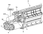
図13は、参考構成例の現像装置4の説明図である。
図13に示すように、参考構成例の現像装置4は、他のスクリュ部材とは独立した排出スクリュ2a用の排出駆動源205を備えている。排出駆動源205は不図示のモータ及び電磁クラッチなどを備えており、制御部700が電磁クラッチによる駆動伝達のON−FF制御を行う。排出駆動源205のON−OFF制御を行うことにより、実施例と同様に供給スクリュ8、攪拌スクリュ11及び回収スクリュ6などの現像装置4の他のスクリュ部材が定常回転であっても、排出スクリュ2aを間欠動作とすることが可能となる。
[ Reference configuration example ]
Next, a reference configuration example for intermittently rotating the
FIG. 13 is an explanatory diagram of the developing
As shown in FIG. 13, the developing
上述の実施形態では、現像剤担持体である現像ローラ5や各現像剤搬送路を設けた現像装置4の現像ケーシング内から排出現像剤を排出させる排出搬送路2内の現像剤に対して間欠的に衝撃を与える構成について説明した。
排出現像剤が搬送路の内壁に固着する不具合は、排出搬送路2だけでなく、排出搬送路2によって現像装置4の現像ケーシングから排出され、排出現像剤収容部である排出現像剤タンク600に到るまでの排出搬送路である排出現像剤移送パイプ601においても生じる不具合である。
よって、排出スクリュ2aと同様に排出収容搬送部材である排出収容スクリュ602を間欠的に駆動させてもよい。詳しくは、排出収容スクリュ駆動源603が不図示のモータ及び電磁クラッチなどを備えており、制御部700が電磁クラッチによる駆動伝達のON−FF制御を行う。排出収容スクリュ駆動源603のON−OFF制御を行うことにより、排出収容スクリュ602を間欠的に回転させることができ、排出現像剤移送パイプ601の内壁に排出現像剤が固着することを防止することができるので、排出現像剤を排出現像剤タンク600まで良好に搬送することが出来る。
In the above-described embodiment, the developer in the discharge conveyance path 2 that discharges the discharged developer from the developing casing of the developing
The problem that the discharged developer adheres to the inner wall of the conveyance path is not only due to the discharge conveyance path 2 but also discharged from the developing casing of the developing
Therefore, similarly to the
本実施形態の現像装置4では、排出スクリュ2aを間欠駆動させることにより、排出搬送路2中の排出現像剤に対して間欠的に衝撃を与える構成について説明した。排出搬送路2中の排出現像剤に対して間欠的に衝撃を与える構成としては排出スクリュ2aを間欠駆動させる構成に限るものではない。例えば、排出スクリュ2aの羽部に接触する程度の突起部を排出搬送路2の内壁に設けても良い。このような突起部を設けることにより、排出スクリュ2aが1回転するたびに羽部が突起部に接触し、排出スクリュ2aが振動して、排出搬送路2中の排出現像剤に対して間欠的に衝撃を与えることが出来る。
In the developing
以上、本実施形態によれば、現像剤を表面上に担持して回転し、潜像担持体である感光体1と対向する箇所で感光体1の表面の潜像にトナーを供給して現像する現像剤担持体である現像ローラ5と、現像剤を搬送する現像剤搬送部材である供給スクリュ8を備え、現像ローラ5に現像剤を供給する現像剤供給領域では現像ローラ5に現像剤を供給しながら現像剤を搬送する供給搬送路9を備えた現像剤搬送路と、現像剤搬送路に現像剤を補給する現像剤補給手段であるトナー補給制御装置と、現像剤を現像装置4の装置外部に搬送する排出搬送路2と、排出搬送路2中の現像剤に搬送力を付与する排出搬送部材である排出スクリュ2aと、現像剤搬送路中の現像剤の少なくとも一部を排出現像剤として排出搬送路2へ排出する現像剤排出手段である現像剤排出口94とを有する現像装置において、排出搬送路2中の排出現像剤に対して間欠的に衝撃を与えることにより、排出搬送路2内の排出スクリュ2aの搬送力が及ばない箇所の排出現像剤にも動きが生じ、排出現像剤の凝集をほぐすことが出来る。これにより、凝集した排出現像剤が排出搬送路2内で固着することを防止することができ、排出現像剤を現像装置4外に良好に搬送することができる。
また、排出搬送部材である排出スクリュ2aによる搬送力の付与を間欠的に行うことによって、排出搬送路2中の排出現像剤に対して間欠的に衝撃を与えることができ、凝集した排出現像剤が排出搬送路2内で固着することを防止することができ、排出現像剤を現像装置4外に良好に搬送することができる。
また、排出搬送部材である排出スクリュ2aは現像剤排出手段である現像剤排出口94と対向しているため、排出スクリュ2aを常時高速回転させていると、排出スクリュ2aが排出搬送路2内の排出現像剤を現像剤排出口94から逆流させてしまい、供給搬送路9内に滞留させてしまうおそれがあった。これに対して、現像装置4であれば、間欠駆動によって排出スクリュ2aが間欠回転であるので、排出スクリュ2aが現像剤を跳ね上げてしまい、現像剤が現像剤排出口94から逆流して供給搬送路9内で滞留してしまうことを低減可能である。
また、排出搬送部材は回転軸と回転軸に螺旋状に設けられた羽部とを備え、回転することにより回転軸方向に現像剤を搬送する排出スクリュで2aあり、供給スクリュ8の駆動源、供給スクリュ8、偏心カム801、揺動レバー201、及びワンウェイクラッチ203等から構成される排出スクリュ間欠回転手段によって排出スクリュ2aを間欠的に回転させることにより、搬送力の付与を間欠的に行うことによって、排出搬送路2中の排出現像剤に対して間欠的に衝撃を与えることができ、凝集した排出現像剤が排出搬送路2内で固着することを防止することができ、排出現像剤を現像装置4外に良好に搬送することができる。
また、供給スクリュ8の駆動源から駆動力が伝達されて連続的に回転駆動する回転駆動部材である偏心カム801を備え、排出スクリュ間欠回転手段は偏心カム801の連続的な回転の駆動力を間欠的な回転の駆動力に変換して排出スクリュ2aに伝達する間欠回転伝達手段を備えることにより、排出スクリュ2a用の駆動源を設ける必要が無くなり、省スペース化、低コスト化を図ることができる。
また、回転駆動部材である偏心カム801が回転運動することによって、排出スクリュ2aの回転軸を揺動中心として揺動する揺動部材である揺動レバー201と、揺動レバー201の揺動運動の一方向の運動を排出スクリュ2aに伝達して、逆方向に戻る運動は伝達しないワンウェイクラッチ203とを備えることにより、偏心カム801の連続的な回転の駆動力を間欠的な回転の駆動力に変換して排出スクリュ2aに伝達することが出来るようになる。
また、排出スクリュ2aに駆動力を伝達する排出スクリュ駆動源である排出駆動源205と、排出スクリュ駆動源の駆動を制御する排出駆動源制御手段である制御部700とを備え、制御部700が排出スクリュ2aを間欠的に回転させるように排出駆動源205を制御することによって、排出搬送部材である排出スクリュ2aによる搬送力の付与を間欠的に行うことが出来る。
また、排出搬送路2が水平方向または上昇方向に搬送する場合、特に排出現像剤の詰まりが発生しやすくなるが、排出スクリュ2aを間欠駆動することによって、排出現像剤を水平方向に搬送する現像装置4であっても排出現像剤の詰まりの発生を防止することが出来る。
また、使用する現像剤が、キャリアとトナーとを含む2成分現像剤である場合、現像で消費されないキャリアが劣化して画像不良の原因となるが、トナー補給口95からキャリアを含んだプレミックストナーの補給がなされ、現像剤排出口94から劣化したキャリアを含んだ現像剤を排出することができるので、現像装置4内のキャリアを入れ替えることができ、良好な画像形成を行うことが出来る。
また、少なくとも供給搬送路9、攪拌搬送路10及び回収搬送路7からなる現像剤搬送路と現像剤担持体である現像ローラ5を設けた現像装置4の現像ケーシング内の排出搬送路2中の現像剤に対して間欠的に衝撃を与えることにより、排出現像剤を良好に現像ケーシングの外に排出することが出来る。
また、少なくとも供給搬送路9、攪拌搬送路10及び回収搬送路7からなる現像剤搬送路と現像剤担持体である現像ローラ5を設けた現像装置4の現像ケーシングから排出され、排出現像剤を収容する排出現像剤収容部である排出現像剤タンク600に到るまでの排出搬送路である排出現像剤移送パイプ601中の現像剤に対して間欠的に衝撃を与えるにより、現像ケーシングから排出された排出現像剤を排出現像剤タンク600まで良好に搬送することが出来る。
また、少なくとも潜像担持体である感光体1と、感光体1表面を帯電させるための帯電手段である帯電器と、感光体1上に静電潜像を形成するための潜像形成手段である光書込ユニット21と、静電潜像を現像してトナー像化するための現像手段とを有する画像形成装置である複写機500が、現像手段として、現像装置4を備えることにより、排出現像剤を現像装置4外に良好に搬送することができるため、現像装置4内のキャリアを入れ替えることができ、良好な画像形成を行うことが出来る。
また、潜像を担持する潜像担持体である感光体1と、感光体1上の潜像を現像する現像手段とを備える画像形成装置である複写機500における少なくとも感光体1と現像手段とを1つのユニットとして共通の保持体に保持させて複写機500本体に対して着脱可能にしたプロセスカートリッジ18が現像手段として現像装置4を備えることにより、排出現像剤を現像装置4外に良好に搬送することができるため、現像装置4内のキャリアを入れ替えることができ、良好な画像形成を行うことが出来る現像装置4の複写機500に対する着脱を容易にすることができる。
As described above, according to the present embodiment, the developer is carried on the surface and rotated, and the toner is supplied to the latent image on the surface of the photoconductor 1 at a position facing the photoconductor 1 as the latent image carrier and developed. A developing
Further, by intermittently applying the conveyance force by the
Further, since the
The discharge conveying member includes a rotation shaft and a wing portion spirally provided on the rotation shaft. The
In addition, an
Further, when the
The
Further, when the discharge conveyance path 2 is conveyed in the horizontal direction or the upward direction, clogging of the discharged developer is particularly likely to occur. However, the development in which the discharged developer is conveyed in the horizontal direction by intermittently driving the
Further, when the developer to be used is a two-component developer containing a carrier and a toner, the carrier that is not consumed in the development deteriorates and causes image defects. Since the toner is replenished and the developer including the deteriorated carrier can be discharged from the
Further, in the discharge conveyance path 2 in the developing casing of the developing
Further, the developer is discharged from the developing casing of the developing
Further, at least a photosensitive member 1 as a latent image carrier, a charger as a charging unit for charging the surface of the photosensitive member 1, and a latent image forming unit for forming an electrostatic latent image on the photosensitive member 1. A copying machine 500, which is an image forming apparatus having a certain optical writing unit 21 and a developing unit for developing an electrostatic latent image into a toner image, includes the developing
In addition, at least the photosensitive member 1 and the developing unit in the copying machine 500 that is an image forming apparatus including the photosensitive member 1 that is a latent image carrier that carries a latent image and a developing unit that develops the latent image on the photosensitive member 1. The process cartridge 18, which is held on a common holder as a unit and can be attached to and detached from the copying machine 500 main body, includes the developing
1 感光体
2 排出搬送路
2a 排出スクリュ
4 現像装置
5 現像ローラ
6 回収スクリュ
7 回収搬送路
8 供給スクリュ
9 供給搬送路
10 攪拌搬送路
11 攪拌スクリュ
12 ドクタブレード
14 張架ローラ
15 駆動ローラ
16 二次転写バックアップローラ
17 中間転写ユニット
18 プロセスカートリッジ
20 画像形成ユニット
21 光書込ユニット
22 二次転写装置
23 張架ローラ
24 紙搬送ベルト
25 定着装置
26 定着ベルト
27 加圧ローラ
80 下流端壁面
90 ベルトクリーニング装置
91 供給開口部
92 余剰開口部
93 回収開口部
94 現像剤排出口
95 トナー補給口
100 プリンタ部
110 中間転写ベルト
133 第一仕切り壁
134 第二仕切り壁
135 排出仕切り壁
201 揺動レバー
202 溝部
203 ワンウェイクラッチ
205 排出駆動源
500 複写機
600 排出現像剤タンク
601 排出現像剤移送パイプ
602 排出収容スクリュ
603 排出収容スクリュ駆動源
604 現像剤は現像剤受入れ口
700 制御部
801 偏心カム
802 突起部
DESCRIPTION OF SYMBOLS 1 Photoconductor 2
Claims (8)
現像剤を搬送する現像剤搬送部材を備え、該現像剤担持体に現像剤を供給する現像剤供給領域では該現像剤担持体に現像剤を供給しながら現像剤を搬送する現像剤搬送路と、
該現像剤搬送路に現像剤を補給する現像剤補給手段と、
現像剤を現像装置の装置外部に搬送する排出搬送路と、
該排出搬送路中の現像剤に搬送力を付与する排出搬送部材と、
該現像剤搬送路中の現像剤の少なくとも一部を排出現像剤として該排出搬送路へ排出する現像剤排出手段とを有する現像装置において、
上記排出搬送部材による搬送力の付与を間欠的に行うことによって、上記排出搬送路中の排出現像剤に対して間欠的に衝撃を与える構成であり、
上記排出搬送部材は回転軸と該回転軸に螺旋状に設けられた羽部とを備え、回転することにより該回転軸方向に現像剤を搬送する排出スクリュであり、
該排出スクリュを間欠的に回転させる排出スクリュ間欠回転手段を備え、
駆動源から駆動力が伝達されて連続的に回転駆動する回転駆動部材を備え、
上記排出スクリュ間欠回転手段は該回転駆動部材の連続的な回転の駆動力を間欠的な回転の駆動力に変換して該排出スクリュに伝達する間欠回転伝達手段を備え、
上記現像剤搬送部材は、回転軸と該回転軸に螺旋状に設けられた羽部とを備え、回転することにより該回転軸方向に現像剤を搬送する現像剤搬送スクリュであり、
上記駆動源は、該現像剤搬送スクリュを回転駆動するものであり、上記回転駆動部材を該現像剤搬送スクリュの軸方向端部に設け、
上記間欠回転伝達手段は、上記回転駆動部材が回転運動することによって、上記排出スクリュの回転軸を揺動中心として揺動する揺動部材と、
該揺動部材と該排出スクリュとを接続するワンウェイクラッチとを備え、
該ワンウェイクラッチは、該揺動部材の揺動運動の一方向の運動を該排出スクリュの回転軸に伝達して、逆方向に戻る運動は伝達しないことを特徴とする現像装置。 A developer carrying member that rotates by carrying a developer on the surface, and supplies toner to the latent image on the surface of the latent image carrying member at a position facing the latent image carrying member;
A developer transport member that transports the developer while supplying the developer to the developer carrier in a developer supply region that includes a developer transport member that transports the developer and supplies the developer to the developer carrier; ,
Developer supplying means for supplying developer to the developer conveying path;
A discharge conveying path for conveying the developer to the outside of the developing device;
A discharge conveying member for applying a conveying force to the developer in the discharge conveying path;
In a developing device having developer discharging means for discharging at least a part of the developer in the developer transport path to the discharge transport path as a discharged developer,
By intermittently applying the transport force by the discharge transport member, it is configured to intermittently impact the discharged developer in the discharge transport path,
The discharge conveyance member is a discharge screw that includes a rotation shaft and a wing provided spirally on the rotation shaft, and conveys the developer in the rotation axis direction by rotating,
Discharge screw intermittent rotation means for intermittently rotating the discharge screw,
A rotation driving member that continuously rotates and receives a driving force transmitted from a driving source;
The discharge screw intermittent rotation means includes intermittent rotation transmission means for converting a continuous rotation driving force of the rotation driving member into an intermittent rotation driving force and transmitting it to the discharge screw.
The developer conveying member is a developer conveying screw that includes a rotating shaft and a blade provided spirally on the rotating shaft, and conveys the developer in the rotating shaft direction by rotating.
The drive source is for rotationally driving the developer transport screw, and the rotational drive member is provided at an axial end of the developer transport screw .
The intermittent rotation transmission means includes a swinging member that swings about the rotation shaft of the discharge screw as a swing center by the rotational drive member rotating,
A one-way clutch that connects the swing member and the discharge screw;
The developing device according to claim 1, wherein the one-way clutch transmits a unidirectional movement of the oscillating member to the rotating shaft of the discharge screw, and does not transmit a reverse movement .
上記排出搬送部材は上記現像剤排出手段に対向していることを特徴とする現像装置。 The developing device according to claim 1.
The developing device according to claim 1, wherein the discharge conveying member faces the developer discharging means .
上記排出搬送路は水平方向または上昇方向に現像剤を搬送することを特徴とする現像装置。 The developing device 請 Motomeko 1 or 2,
The developing apparatus according to claim 1, wherein the discharge conveyance path conveys the developer in a horizontal direction or a rising direction.
使用する現像剤が、キャリアとトナーとを含む2成分現像剤であることを特徴とする現像装置。 The developing device according to claim 1, 2 or 3,
A developing device, wherein the developer to be used is a two-component developer including a carrier and a toner.
少なくとも上記現像剤担持体と上記現像剤搬送路とを設けた現像ケーシング内の上記排出搬送路中の現像剤に対して間欠的に衝撃を与えることを特徴とする現像装置。 The developing device according to claim 1, 2, 3 or 4,
A developing device characterized in that an impact is intermittently applied to the developer in the discharge conveying path in a developing casing provided with at least the developer carrying member and the developer conveying path.
少なくとも上記現像剤担持体と上記現像剤搬送路とを設けた現像ケーシングから排出され、排出現像剤を収容する排出現像剤収容部に到るまでの上記排出搬送路中の現像剤に対して間欠的に衝撃を与えることを特徴とする現像装置。 The developing device according to claim 1, 2, 3, 4 or 5,
Discharged from the developer casing provided with at least the developer carrier and the developer transport path, and intermittent with respect to the developer in the discharge transport path until reaching the discharged developer storage section for storing the discharged developer. A developing device characterized in that a shock is applied.
該潜像担持体表面を帯電させるための帯電手段と、
該潜像担持体上に静電潜像を形成するための潜像形成手段と、
該静電潜像を現像してトナー像化するための現像手段とを有する画像形成装置において、
該現像手段として、請求項1、2、3、4、5または6に記載の現像装置を用いることを特徴とする画像形成装置。 At least a latent image carrier;
Charging means for charging the surface of the latent image carrier;
Latent image forming means for forming an electrostatic latent image on the latent image carrier;
In an image forming apparatus having developing means for developing the electrostatic latent image into a toner image,
As developing means, according to claim 1, 2, 3, 4, the image forming apparatus, which comprises using a developing device according to 6 was 5 or.
上記現像手段として、請求項1、2、3、4、5または6の何れかに記載の現像装置を用いたことを特徴とするプロセスカートリッジ。 In an image forming apparatus comprising a latent image carrier that carries a latent image and a developing unit that develops the latent image on the latent image carrier, at least the latent image carrier and the developing unit are shared as one unit. In the process cartridge that is held by the holding body and is detachable from the image forming apparatus main body,
As the developing means, according to claim 1, 2, 3, 4, the process cartridge characterized by using a developing device according to any one 5 or the 6.
Priority Applications (1)
| Application Number | Priority Date | Filing Date | Title |
|---|---|---|---|
| JP2007273957A JP5124231B2 (en) | 2007-06-19 | 2007-10-22 | Developing device, image forming apparatus, and process cartridge |
Applications Claiming Priority (3)
| Application Number | Priority Date | Filing Date | Title |
|---|---|---|---|
| JP2007160953 | 2007-06-19 | ||
| JP2007160953 | 2007-06-19 | ||
| JP2007273957A JP5124231B2 (en) | 2007-06-19 | 2007-10-22 | Developing device, image forming apparatus, and process cartridge |
Publications (2)
| Publication Number | Publication Date |
|---|---|
| JP2009025784A JP2009025784A (en) | 2009-02-05 |
| JP5124231B2 true JP5124231B2 (en) | 2013-01-23 |
Family
ID=39795487
Family Applications (1)
| Application Number | Title | Priority Date | Filing Date |
|---|---|---|---|
| JP2007273957A Expired - Fee Related JP5124231B2 (en) | 2007-06-19 | 2007-10-22 | Developing device, image forming apparatus, and process cartridge |
Country Status (3)
| Country | Link |
|---|---|
| US (1) | US8145101B2 (en) |
| EP (1) | EP2006747B1 (en) |
| JP (1) | JP5124231B2 (en) |
Families Citing this family (19)
| Publication number | Priority date | Publication date | Assignee | Title |
|---|---|---|---|---|
| JP2008046240A (en) * | 2006-08-11 | 2008-02-28 | Ricoh Co Ltd | Developing device, process cartridge, and image forming apparatus |
| US7881641B2 (en) * | 2008-03-31 | 2011-02-01 | Seiko Epson Corporation | Developing cartridge, developing device, and image forming apparatus |
| JP2009258445A (en) * | 2008-04-17 | 2009-11-05 | Ricoh Co Ltd | Developer supply device and image forming apparatus |
| JP2011112775A (en) | 2009-11-25 | 2011-06-09 | Ricoh Co Ltd | Developing device, image-forming device, and process cartridge |
| JP5644127B2 (en) * | 2010-02-10 | 2014-12-24 | 株式会社リコー | Image forming apparatus and developing device used therefor |
| JP5633726B2 (en) * | 2010-03-11 | 2014-12-03 | 富士ゼロックス株式会社 | Developer collection container and image forming apparatus |
| US8923726B2 (en) | 2011-04-21 | 2014-12-30 | Ricoh Company, Ltd. | Image forming apparatus incorporating developing device with first and second seals |
| JP2012230203A (en) | 2011-04-25 | 2012-11-22 | Ricoh Co Ltd | Development device and image forming apparatus |
| JP5751716B2 (en) * | 2012-02-14 | 2015-07-22 | 京セラドキュメントソリューションズ株式会社 | Developing device and image forming apparatus including the same |
| JP6094336B2 (en) * | 2013-04-03 | 2017-03-15 | 富士ゼロックス株式会社 | Developer recovery apparatus and image forming apparatus |
| KR101622288B1 (en) * | 2014-11-24 | 2016-05-18 | 주식회사 신도리코 | Developer discharging apparatus for image forming apparatus |
| US9658576B2 (en) | 2014-12-11 | 2017-05-23 | Ricoh Company, Ltd. | Developing device, and process cartridge and image forming apparatus incorporating same |
| EP3043212B1 (en) | 2015-01-09 | 2020-07-22 | Ricoh Company, Ltd. | Developing device, process cartridge, and image forming apparatus including same |
| JP6860281B2 (en) | 2015-01-14 | 2021-04-14 | 株式会社リコー | Image forming device |
| JP6488866B2 (en) | 2015-05-08 | 2019-03-27 | 株式会社リコー | Carrier and developer |
| JP2017003858A (en) | 2015-06-12 | 2017-01-05 | 株式会社リコー | Carrier and developer |
| JP6627965B2 (en) | 2016-03-17 | 2020-01-08 | 株式会社リコー | Electrostatic latent image developer carrier, two-component developer, supply developer, image forming apparatus, and toner storage unit |
| US10324388B2 (en) | 2016-03-18 | 2019-06-18 | Ricoh Company, Ltd. | Toner, toner stored unit, image forming apparatus, and image forming method |
| JP7468048B2 (en) * | 2020-03-25 | 2024-04-16 | 富士フイルムビジネスイノベーション株式会社 | Developer supply device and image forming apparatus |
Family Cites Families (21)
| Publication number | Priority date | Publication date | Assignee | Title |
|---|---|---|---|---|
| GB818080A (en) | 1956-05-07 | 1959-08-12 | Ernest William Dorton | Improvements in or relating to clutches |
| EP0203119B1 (en) | 1984-11-26 | 1988-10-12 | Schweizerische Aluminium AG | Utilisation of a device for conveying flowing materials |
| JPS61272769A (en) * | 1985-05-28 | 1986-12-03 | Minolta Camera Co Ltd | Dry type developing device |
| JPH03196081A (en) | 1989-12-25 | 1991-08-27 | Mutoh Ind Ltd | Discarded toner conveying device |
| JPH0553430A (en) * | 1991-08-27 | 1993-03-05 | Fujitsu Ltd | Developer discharging device for electrophotographic image forming apparatus |
| JPH1055098A (en) * | 1996-08-09 | 1998-02-24 | Seiko Epson Corp | Developing device |
| JPH10161499A (en) * | 1996-11-29 | 1998-06-19 | Hitachi Koki Co Ltd | Method of discharging developer of electrophotographic apparatus |
| JP2000112238A (en) * | 1998-09-30 | 2000-04-21 | Fuji Xerox Co Ltd | Developing device |
| JP3966639B2 (en) * | 1999-03-31 | 2007-08-29 | 株式会社沖データ | Image recording device |
| JP3893232B2 (en) * | 1999-11-22 | 2007-03-14 | 株式会社リコー | Image forming apparatus |
| JP3750483B2 (en) * | 2000-04-17 | 2006-03-01 | 富士ゼロックス株式会社 | Toner supply device |
| JP2003337469A (en) | 2002-05-20 | 2003-11-28 | Ricoh Co Ltd | Developing device and image forming device |
| JP2004302366A (en) * | 2003-04-01 | 2004-10-28 | Canon Inc | Image forming device |
| JP2005315909A (en) * | 2004-04-26 | 2005-11-10 | Canon Inc | Image forming apparatus |
| KR100610370B1 (en) * | 2004-09-22 | 2006-08-10 | 삼성전자주식회사 | Developer recovery apparatus and image forming apparatus having same |
| JP2007108225A (en) * | 2005-10-11 | 2007-04-26 | Canon Inc | Image forming apparatus |
| JP4953634B2 (en) | 2006-01-05 | 2012-06-13 | 株式会社リコー | Developing device and image forming apparatus |
| JP4820689B2 (en) | 2006-05-15 | 2011-11-24 | 株式会社リコー | Developing device, process cartridge, and image forming apparatus |
| JP2008046240A (en) | 2006-08-11 | 2008-02-28 | Ricoh Co Ltd | Developing device, process cartridge, and image forming apparatus |
| JP5066898B2 (en) * | 2006-11-21 | 2012-11-07 | 富士ゼロックス株式会社 | Developer transport device and image forming apparatus |
| US7894760B2 (en) * | 2007-09-10 | 2011-02-22 | Kabushiki Kaisha Toshiba | Disposed toner collecting device of image forming apparatus |
-
2007
- 2007-10-22 JP JP2007273957A patent/JP5124231B2/en not_active Expired - Fee Related
-
2008
- 2008-06-09 US US12/135,413 patent/US8145101B2/en not_active Expired - Fee Related
- 2008-06-19 EP EP08158538.2A patent/EP2006747B1/en not_active Ceased
Also Published As
| Publication number | Publication date |
|---|---|
| US8145101B2 (en) | 2012-03-27 |
| JP2009025784A (en) | 2009-02-05 |
| EP2006747B1 (en) | 2019-03-06 |
| EP2006747A1 (en) | 2008-12-24 |
| US20080317508A1 (en) | 2008-12-25 |
Similar Documents
| Publication | Publication Date | Title |
|---|---|---|
| JP5124231B2 (en) | Developing device, image forming apparatus, and process cartridge | |
| JP5152628B2 (en) | Developing device, image forming apparatus | |
| JP4820689B2 (en) | Developing device, process cartridge, and image forming apparatus | |
| JP4764743B2 (en) | Developing device, image forming apparatus | |
| JP5644127B2 (en) | Image forming apparatus and developing device used therefor | |
| JP2008046240A (en) | Developing device, process cartridge, and image forming apparatus | |
| JP6440016B2 (en) | Developing device, process cartridge, and image forming apparatus | |
| JP2008249835A (en) | Developing device, image forming apparatus | |
| JP5277587B2 (en) | Image forming apparatus | |
| JP2008292972A (en) | Developing device, image forming apparatus, process cartridge, and image forming method | |
| JP5037253B2 (en) | Developing device, image forming apparatus | |
| JP5240557B2 (en) | Developing device, image forming apparatus, and process cartridge | |
| JP6440017B2 (en) | Developing device and image forming apparatus | |
| JP5442186B2 (en) | Developing device, image forming apparatus, and process cartridge | |
| JP5158473B2 (en) | Developing device and image forming apparatus | |
| JP2009063710A (en) | Developing device and image forming apparatus | |
| JP5081655B2 (en) | Agent-filled developer container manufacturing method, agent-filled developer container, developer supply device, and image forming apparatus | |
| JP5252329B2 (en) | Developing device, image forming apparatus | |
| JP6128426B2 (en) | Developer supply device and image forming apparatus | |
| JP5037254B2 (en) | Developing device, image forming apparatus | |
| JP2016080840A (en) | Developing device and image forming apparatus | |
| JP4971054B2 (en) | Developing device, process cartridge, and image forming apparatus | |
| JP2010217328A (en) | Developing device, image-forming device, and process cartridge | |
| JP2010102125A (en) | Developing device and image forming apparatus | |
| JP6128427B2 (en) | Developer supply device and image forming apparatus |
Legal Events
| Date | Code | Title | Description |
|---|---|---|---|
| A621 | Written request for application examination |
Free format text: JAPANESE INTERMEDIATE CODE: A621 Effective date: 20100709 |
|
| A977 | Report on retrieval |
Free format text: JAPANESE INTERMEDIATE CODE: A971007 Effective date: 20120412 |
|
| A131 | Notification of reasons for refusal |
Free format text: JAPANESE INTERMEDIATE CODE: A131 Effective date: 20120420 |
|
| A521 | Written amendment |
Free format text: JAPANESE INTERMEDIATE CODE: A523 Effective date: 20120619 |
|
| A131 | Notification of reasons for refusal |
Free format text: JAPANESE INTERMEDIATE CODE: A131 Effective date: 20120713 |
|
| A521 | Written amendment |
Free format text: JAPANESE INTERMEDIATE CODE: A523 Effective date: 20120911 |
|
| TRDD | Decision of grant or rejection written | ||
| A01 | Written decision to grant a patent or to grant a registration (utility model) |
Free format text: JAPANESE INTERMEDIATE CODE: A01 Effective date: 20120928 |
|
| A01 | Written decision to grant a patent or to grant a registration (utility model) |
Free format text: JAPANESE INTERMEDIATE CODE: A01 |
|
| A61 | First payment of annual fees (during grant procedure) |
Free format text: JAPANESE INTERMEDIATE CODE: A61 Effective date: 20121029 |
|
| FPAY | Renewal fee payment (event date is renewal date of database) |
Free format text: PAYMENT UNTIL: 20151102 Year of fee payment: 3 |
|
| R150 | Certificate of patent or registration of utility model |
Free format text: JAPANESE INTERMEDIATE CODE: R150 Ref document number: 5124231 Country of ref document: JP Free format text: JAPANESE INTERMEDIATE CODE: R150 |
|
| LAPS | Cancellation because of no payment of annual fees |