JP6435316B2 - Automatic storage and retrieval system - Google Patents
Automatic storage and retrieval system Download PDFInfo
- Publication number
- JP6435316B2 JP6435316B2 JP2016503353A JP2016503353A JP6435316B2 JP 6435316 B2 JP6435316 B2 JP 6435316B2 JP 2016503353 A JP2016503353 A JP 2016503353A JP 2016503353 A JP2016503353 A JP 2016503353A JP 6435316 B2 JP6435316 B2 JP 6435316B2
- Authority
- JP
- Japan
- Prior art keywords
- storage
- pick face
- pick
- common
- rover
- Prior art date
- Legal status (The legal status is an assumption and is not a legal conclusion. Google has not performed a legal analysis and makes no representation as to the accuracy of the status listed.)
- Active
Links
- 238000003860 storage Methods 0.000 title claims description 234
- 241001061260 Emmelichthys struhsakeri Species 0.000 claims description 94
- 238000012546 transfer Methods 0.000 claims description 23
- 239000012636 effector Substances 0.000 claims description 17
- 238000000034 method Methods 0.000 claims description 9
- 238000003780 insertion Methods 0.000 claims description 4
- 230000037431 insertion Effects 0.000 claims description 4
- 238000004891 communication Methods 0.000 claims description 3
- 230000000295 complement effect Effects 0.000 claims description 2
- 241001061257 Emmelichthyidae Species 0.000 claims 1
- 238000010586 diagram Methods 0.000 description 27
- 238000000605 extraction Methods 0.000 description 6
- 239000012530 fluid Substances 0.000 description 6
- 239000000463 material Substances 0.000 description 5
- 230000008901 benefit Effects 0.000 description 2
- 238000012790 confirmation Methods 0.000 description 2
- 238000001125 extrusion Methods 0.000 description 2
- 238000012986 modification Methods 0.000 description 2
- 230000004048 modification Effects 0.000 description 2
- 229910000831 Steel Inorganic materials 0.000 description 1
- 239000000853 adhesive Substances 0.000 description 1
- 230000001070 adhesive effect Effects 0.000 description 1
- 230000004075 alteration Effects 0.000 description 1
- 230000001419 dependent effect Effects 0.000 description 1
- 230000005611 electricity Effects 0.000 description 1
- 238000009434 installation Methods 0.000 description 1
- 230000013011 mating Effects 0.000 description 1
- 230000007246 mechanism Effects 0.000 description 1
- 238000003825 pressing Methods 0.000 description 1
- 230000009467 reduction Effects 0.000 description 1
- 230000003068 static effect Effects 0.000 description 1
- 239000010959 steel Substances 0.000 description 1
- 230000008685 targeting Effects 0.000 description 1
- 230000007704 transition Effects 0.000 description 1
- 239000011800 void material Substances 0.000 description 1
- 238000003466 welding Methods 0.000 description 1
Images


Classifications
-
- B—PERFORMING OPERATIONS; TRANSPORTING
- B65—CONVEYING; PACKING; STORING; HANDLING THIN OR FILAMENTARY MATERIAL
- B65G—TRANSPORT OR STORAGE DEVICES, e.g. CONVEYORS FOR LOADING OR TIPPING, SHOP CONVEYOR SYSTEMS OR PNEUMATIC TUBE CONVEYORS
- B65G1/00—Storing articles, individually or in orderly arrangement, in warehouses or magazines
- B65G1/02—Storage devices
- B65G1/04—Storage devices mechanical
- B65G1/137—Storage devices mechanical with arrangements or automatic control means for selecting which articles are to be removed
- B65G1/1373—Storage devices mechanical with arrangements or automatic control means for selecting which articles are to be removed for fulfilling orders in warehouses
-
- B—PERFORMING OPERATIONS; TRANSPORTING
- B65—CONVEYING; PACKING; STORING; HANDLING THIN OR FILAMENTARY MATERIAL
- B65G—TRANSPORT OR STORAGE DEVICES, e.g. CONVEYORS FOR LOADING OR TIPPING, SHOP CONVEYOR SYSTEMS OR PNEUMATIC TUBE CONVEYORS
- B65G1/00—Storing articles, individually or in orderly arrangement, in warehouses or magazines
- B65G1/02—Storage devices
- B65G1/04—Storage devices mechanical
- B65G1/0492—Storage devices mechanical with cars adapted to travel in storage aisles
Landscapes
- Engineering & Computer Science (AREA)
- Mechanical Engineering (AREA)
- Warehouses Or Storage Devices (AREA)
Description
[関連出願の相互参照]
本出願は、2013年3月15日に出願された米国仮特許出願第61/790,801号明細書に基づく非仮出願であって、前記仮出願の優先権を主張する。この出願の開示内容の全ては、参照により本明細書に組み込まれる。
[Cross-reference of related applications]
This application is a non-provisional application based on US Provisional Patent Application No. 61 / 790,801 filed on March 15, 2013, and claims the priority of the provisional application. The entire disclosure of this application is incorporated herein by reference.
[技術分野]
例示的実施形態は一般的に、材料操作システム、特に、材料操作システム内での物品の搬送および保管に関する。
[Technical field]
Exemplary embodiments generally relate to a material handling system, and more particularly to the transport and storage of articles within a material handling system.
一般的に、物品の保管、たとえば倉庫内での保管には、大きな建築物または保管構造空間と、対応する設置面積を要する。保管庫に物品を配置し、保管庫から物品を取り出すために、自動車両またはロボットが倉庫内で使用され得る。 Generally, storage of articles, for example, storage in a warehouse, requires a large building or storage structure space and a corresponding installation area. A motor vehicle or robot can be used in the warehouse to place the article in the repository and to remove the article from the repository.
物品を保管構造から取り出すために、物品を効率的に取り出すことが可能である自動車両を有することは有利となり得る。また、保管構造の保管密度を増加させるために、保管庫の複数レベルにアクセス可能である自動車両を有することも有利となり得る。 It may be advantageous to have a motor vehicle that can efficiently remove items in order to remove the items from the storage structure. It may also be advantageous to have a motor vehicle that is accessible to multiple levels of storage in order to increase the storage density of the storage structure.
開示される実施形態の上記の態様および他の特徴が、添付の図面に関連して以下の記述において説明される。 The above aspects and other features of the disclosed embodiments are set forth in the following description with reference to the accompanying drawings.
図1は、開示される実施形態の態様に係る保管および取出システムを概略的に示している。開示される実施形態の態様は図面に関連して説明されるが、開示される実施形態の態様は多くの代替形態において実施され得ることを理解すべきである。加えて、任意の適切なサイズ、形状、または種類の構成要素または材料が使用され得る。 FIG. 1 schematically illustrates a storage and retrieval system according to aspects of the disclosed embodiment. Although aspects of the disclosed embodiments are described with reference to the drawings, it should be understood that aspects of the disclosed embodiments can be implemented in many alternative forms. In addition, any suitable size, shape, or type of component or material may be used.
開示される実施形態の態様に従って、保管および取出システム100は、たとえば、小売店から受けた、ケースユニットの注文を履行するために、小売流通センタまたは倉庫において稼動してもよく、たとえばこれらは、2011年12月15日に出願された米国特許出願第13/326、674号明細書に記載され、その開示内容の全ては、参照により本明細書に組み込まれる。
In accordance with aspects of the disclosed embodiment, the storage and
保管および取出システム100は、インフィード移送ステーション170およびアウトフィード移送ステーション160、搬入垂直方向リフト150Aおよび搬出垂直方向リフト150B(一般的に、リフト150と呼ばれる)、保管構造130、ならびに、多数の自律型ローバー110を含んでいてもよい。保管構造130は複数レベルの保管ラックモジュールを含んでいてもよく、各レベルは、(たとえば、それぞれのレベルに提供される)ケースユニットを保管構造130の任意の保管区域とリフト150の任意の棚との間で移送する(図16、ブロック1600)ために、それぞれの保管または取り出し通路130Aおよび移送デッキ130Bを含む。保管通路130A、および移送デッキ130Bはまた、それぞれのレベルに設けられるローバー110が(図16、ブロック1601)、ケースユニットを取り出しストックの中に配置するために保管通路130Aおよび移送デッキ130Bを横断し、注文されたケースユニットを取り出すことを可能とするように構成される。
The storage and
ローバー100は、保管および取出システム100の全体に亘ってケースユニットを運搬および移送することが可能な、任意の適切な自律型車両であってもよい。ローバーの適切な例は、2011年12月5日に出願された米国特許出願第13/326,674号明細書、2010年4月9日に出願された米国特許出願第12/757,312号明細書、2011年12月15日に出願された米国特許出願第13/326,423号明細書、2011年12月15日に出願された米国特許出願第13/326,447号明細書、2011年12月15日に出願された米国特許出願第13/326,505号明細書、2011年12月15日に出願された米国特許出願第13/327,040号明細書、2011年12月15日に出願された米国特許出願第13/326,952号明細書、および2011年12月15日に出願された米国特許出願第13/326,993号明細書において見ることができ、これらは例示目的のためだけのものであり、これらの開示内容の全てが参照により本明細書に組み込まれる。ローバー110は、上述の小売商品のようなケースユニットを保管構造130の1つまたは複数のレベル内の取り出しストックの中に配置し、そして、注文されたケースユニットを、たとえば店や他の適切な場所に出荷するために、注文されたケースユニットを選択的に取り出すように構成される。
Rover 100 may be any suitable autonomous vehicle capable of transporting and transporting case units throughout storage and retrieval
ローバー110および保管および取出システム100の他の適切な機構は、たとえば、任意の適切なネットワーク180を通じて、たとえば、1つまたは複数の中央システム制御コンピュータ(たとえば、制御サーバ)120によって制御され得る。ネットワーク180は、任意の適切な種類および/または適切な数の通信プロトコルを用いた、有線ネットワーク、無線ネットワーク、または有線および無線ネットワークの組み合わせであってもよい。ある態様では、制御サーバ120は、ただ例示的な目的のために、稼働中の全てのシステム構成要素を制御、スケジューリング、モニタリングすること、在庫およびピックフェースを管理すること、および倉庫管理システム2500とインターフェイスで接続することを含む、保管および取出システム100の管理をするように構成された、実質的に同時に実行されるプログラムの集合を含み得る。
The
次に図2を参照すると、ローバー110は、第1の端部110E1、および第1の端部110E1から縦方向(longitudinally)に離間した第2の端部110E2を有するフレーム110Fを含み得る。フレーム110Fは、任意の適切な方法で積載ベイ200内部のピックフェースを支持するように構成された積載ベイ200を形成する。ある態様では、横方向(laterally)に配列されたローラ200Rがピックフェースを支持し、ピックフェースが積載ベイの内部で縦方向に移動することを可能にし得る。本明細書において用いられる「ピックフェース」とは、前後の並び、横の並び、またはその組み合わせで配置された1つまたは複数の商品ケースユニットであってもよいことを注意すべきである。
Referring now to FIG. 2, the
ローバー110は、ピックフェースの端縁または側面210Eに係合し、ローバーフレームおよび/または自動保管および取出システムの全体の基準フレームに対する、1単位としてのピックフェースの積極的な縦方向位置合せを提供するような、(1つまたは複数の)表面を有する移動可能なブレードまたはフェンスのような、1つまたは複数の動作式位置合せ部材202、203を含み得る。1つまたは複数の位置合せ部材202、203の共通の動作式位置合せ表面によるピックフェースの側面210Eの係合および移動による積極的なピックフェース位置合せが、摩擦による位置合せにより起こり得る位置変動を解決し、ピックフェースの位置決め/配置をローバーフレーム110Fから(たとえば、ローバーフレーム110Fに対して)分離させた、信頼性の高いピックフェースの位置決め/配置を達成する。1つまたは複数の位置合せ部材は、一貫し、連続的なラックの保管有用性を可能にし得る。
The
位置合せ部材202、203は、1つもしくは複数のフレーム110Fまたは保管ラックモジュールの保管棚300(図3)に対する所定の位置にピックフェースを位置決めするために、少なくとも部分的に積載ベイ200内部に設置され得る。ある態様では、位置合せ部材202、203は、ピックフェースを形成する(1つまたは複数の)ケースユニットに共通である。位置合せ部材202、203は、ピックフェースを位置決めするためにピックフェース210の側面に係合する押出プレートまたは押出ブレードであってもよい。位置合せ部材202、203は、少なくとも位置合せ部材202、203の1つが積載ベイ内部で縦方向に移動可能であるという意味で、動作式であってもよい。たとえば、図2に見られるように、位置合せ部材203がフレーム110Fに対して縦方向に移動可能である一方で、位置合せ部材202はフレームに対して固定され得る。他の態様においては、位置合せ部材202、203の両方が、フレーム110Fに対して縦方向に移動可能であってもよい。
後述する任意の適切な駆動部220は、後述するような任意の適切な方法で、1つまたは複数の位置合せ部材202、203を駆動させるために、フレームに接続され得る。ローバー110は、位置合せ部材202、203の少なくとも1つの移動を制御するために駆動部に接続された、任意の適切な制御装置110Cを含み得る。一方の位置合せ部材202が固定され、他方の位置合せ部材203が移動可能である場合の、ある態様では、位置合せ部材203が、ピックフェースを、固定された位置合せ部材202に対して寄せる(snug)ように、制御装置は移動可能な位置合せ部材203を制御し得る。少なくとも縦方向におけるピックフェースの境界が認識され、ピックフェースの位置が、固定された位置合せ部材202の位置に基づいて決定され得るように、制御装置は(参照テーブル、センサ、および積載ベイ内部の移動式位置合せブレードの縦方向位置などのような任意の適切な方法で決定される)ピックフェースの幅を認識し得る。位置合せ部材202、203の両方が移動可能である場合の、他の態様において、位置合せ部材202、203の平均の位置(たとえば、位置合せ部材202、203の間の中央線ML)が、ピックフェース210が積載ベッド200の内部で位置する場所(たとえば、ローバーの縦方向に対するピックフェース210の中心線CL)と実質的に一致する(たとえば、同一線上に沿う)ように、制御装置110Cは位置合せ部材202、203の移動を制御し得る。ピックフェースの寄せ(たとえば、ピックフェースを、位置合せ部材202、203を用いて保持する、および/またはピックフェース210の、1つまたは複数のケースユニット210P1、210P2を整列させるために互いに押しつける)も、寄せる力の大きさを制御するために任意の適切な力フィードバックを用いる制御装置110Cによって、制御され得る。制御装置110Cは駆動部の1つまたは複数のモータからの電流を監視し、寄せる力を制御するために、その電流を単独で、または、たとえば、カルマンフィルタ(または他の力推定アルゴリズムもしくはセンサ)とともに用いてもよい。
Any
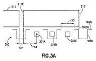
さらに図2、および図3A、図3Bを参照すると、ローバーは、ピックフェース210を積載ベイ200へ、および積載ベイ200から移送するために、フレーム110Fに移動可能に接続された、任意の適切なエンドエフェクタを含み得る。ある態様では、エンドエフェクタは、ピックフェース210を積載ベイ200へ、および積載ベイ200から、持ち上げ、搬送する(一般的に、フィンガ201と呼ばれる)可動式フィンガ201A、201B、201Cを含む。ピックフェースのエッジまたは側面210Eが、フィンガ210Aのようなフィンガから、または、他の任意の適切な積載ベイ200の基準面、フレーム110Fまたは自動保管および取出システムの全体の基準フレームから、所定の距離X1、X2で位置決めされるように、制御装置110Cは位置合せ部材202、203を位置決めしてもよい。これは、ケースオフセットと呼ぶことができる。ケースオフセットは、保管棚300の支持表面300S上のピックフェースの間に任意の適切な間隔を設けるために、実質的に0から、任意の適切な所定の距離X1までの範囲にわたる。ケースユニットまたはピックフェースを、位置合せ部材202、203を用いて位置決めすることで、隣接するケースユニットの間または隣接するピックフェースの間の、間隔または隙間SPを最小にすることが可能となる。ある態様では、位置合せ部材202、203を用いてケースユニットまたはピックフェースを位置合せすることにより、保管棚300上で保管棚300のある特徴に対する所定の位置へのケースユニットまたはピックフェースの配置が可能となる。たとえば、保管棚300の支持表面300Sは、支持表面300Sの各部分が直立部材300Uによって支持される非連続支持表面300SSから形成され得る。直立部材300Uは、直立部材300Uの間へのフィンガ201の挿入を可能にさせる略チャネル形状であり、フィンガは非連続表面300SSの間で垂直に移動する。ある態様では、隣接するケースユニットの間または隣接するピックフェースの間に所定の間隔SPが存在するように、ケースユニットまたはピックフェースの端縁210Eを非連続支持表面300SSから所定の距離で配置するために、ケースユニットまたはピックフェースの位置合せは、少なくとも自動保管および取出システムの全体の基準フレームに関連している。間隔SPは任意の適切な間隔であってよく、ある態様では、非連続支持表面300SSの間の距離X3より小さい。ある態様では、間隔SPは、隣接するケースユニットの間または隣接するピックフェースの間に、割当てられた保管空間への、および割当てられた保管空間からの、ケースユニットまたはピックフェースの接触のない挿入または取り出しを可能とするに十分なだけの間隙を設ける、最小の間隔であってもよい。
Still referring to FIGS. 2, and 3A, 3B, the rover can be any suitable movably
次に図4を参照すると、開示される実施形態の態様によるローバー110の一部が図示される。図4に見られるように、位置合せ部材202、203のそれぞれが、線形ガイド部材401に任意の適切な方法で、移動可能に取り付けられる。たとえば、スライド連結器403A、403Bは、(たとえばそれぞれの位置合せ部材202、203に対し1つの連結器で)線形ガイド部材401に移動可能に取り付けられ得る。位置合せ部材をローラ200R(または他のピックフェース支持部)およびフィンガ201の上方で縦方向の移動を可能にさせるために、位置合せ部材202、203が位置合せ部材202、203の片側で支持される(たとえば、線形ガイド部材401から片持ちされる)ようにスライド連結器403A、403Bは、それぞれの位置合せ部材202、203に連結され得る。線形ガイド部材401は、(たとえば、ローラ200Rのような)積載ベッドのピックフェース支持表面の下に取り付けられ得る。
With reference now to FIG. 4, a portion of a
駆動部220Aは、2自由度駆動部であってもよい。他の態様では、駆動部は2自由度より多い、または2自由度より少ない自由度であってもよい。図4に見られるように、駆動部は共通の駆動部材402を含み、共通の駆動部材は、フレーム110Fに対して移動可能に固定されるように、一方の端部402E1はフレーム110Fに固定され、他方の端部402E2はフレーム110Fの反対の端に固定される。共通の駆動部材は、たとえば、バンド、ベルト、ワイヤなどのような、任意の適切な部材であってもよい。モータ400M1、400M2は、それぞれの位置合せ部材202、203に、任意の適切な方法で取り付けられ得る。各モータは駆動プーリP1を含み、各スライド連結器は従動プーリP2を含み、一組のプーリを形成している。駆動プーリP1と共通の駆動部材402との間の係合が、対応するモータ400M1、400M2が起動した時に、それぞれの位置合せ部材202、203の縦方向の移動を引き起こすように、共通の駆動部材402は、任意の適切な方法で、それぞれの一組のプーリの駆動プーリP1および従動プーリP2の周りで蛇行し、張力を加えられていてもよい。理解できるように、モータ400M1、400M2は、たとえば、ステッピングモータのような、任意の適切なモータであってもよい。制御装置110Cは、位置合せ部材202、203とフレーム110Fとの間に相対動作を生み、開ループ制御(たとえば、モータ指令を通して)または(1つまたは複数のセンサからの位置情報を使用する)閉ループ制御を使用して、ピックフェースを寄せる、および位置決めするために、各モータを制御し得る。理解できるように、1つまたは複数の位置合せ部材202、203の、たとえば、フレームに対する位置を取得するために、任意の適切なセンサがフレーム110F上に設置されてもよい。ある態様では、制御装置に位置データを提供するために、線形ガイド部材401に沿って、または従動プーリP2上にエンコーダが配置されてもよい。
The driving unit 220A may be a two-degree-of-freedom driving unit. In another aspect, the driving unit may have more than two degrees of freedom or less than two degrees of freedom. As shown in FIG. 4, the driving unit includes a
図4Bを参照すると、開示される実施形態の別の態様による、別の2自由度駆動部が示される。図4Bに示される駆動部の作動は上述のものに実質的に類似しているが、しかし、モータ400M1、400M2は任意の適切な方法でフレーム110Fに取り付けられる。この態様では、各モータは対応する閉ループ駆動部材402A、402B(たとえば、ベルト、バンド、ワイヤなど)を駆動し得る。たとえば、各モータは、モータの出力に取り付けられた駆動プーリP1を含み得る。対応する従動プーリP2はフレーム110Fの縦方向の反対側に取り付けられ得る。閉ループ駆動部材402A、402Bは、それぞれの駆動プーリP1および従動プーリP2に巻かれるか、あるいは係合する。それぞれのモータ400M1、400M2が駆動されると、それぞれのスライド連結器403A、403B(およびそれぞれの位置合せ部材202、203)を移動させるために、閉ループ駆動部材402AがプーリP1、P2の周りで回転するように、スライド連結器403Aは閉ループ駆動部材402Aと連結されてもよく、スライド連結器403Bは閉ループ駆動部材402Bと連結されてもよい。
Referring to FIG. 4B, another two degree of freedom drive according to another aspect of the disclosed embodiment is shown. The operation of the drive shown in FIG. 4B is substantially similar to that described above, but the motors 400M1, 400M2 are attached to the
図6A〜図6Dを参照して、ピックフェースのローバー上での位置合せを説明する。フィンガ201は保管棚300に延び(図3A)、ケースユニット210P1、210P2を積載ベイ200の中へ移送する(図2)ために、(たとえば、以下に記載されるようにピックフェースを構築するための同じまたは別の棚の)同じまたは別の保管場所ピックフェースから1つまたは複数のケースユニット210P1、210P2を取り出す。ケースユニット21P1、210P2がたとえば、ローラ200Rの上に配置されるように、フィンガ201は、積載ベイ200のピックフェース支持表面の下方に下降し得る。ローバー制御装置110Cは、位置合せ部材がケースユニット210P1、210P2の側面に接触するまで(図6B)、位置合せ部材203を矢印A1の方向に移動させるため、および位置合せ部材202を矢印A2の方向に移動させるため、モータ400M1、400M2を駆動し得る(図4および図5)。ケースユニット210P1、210P2を縦方向に整列させるために(図6C)、位置合せ部材202、203によって、寄せる力が、上述の通り、ケースユニット210P1、210P2に加えられる。理解できるように、ケースユニット210P1、210P2は、たとえば、移動式寄せ部材110PBおよび固定フェンス110EFを用いて横方向に寄せられてもよく、これは例示目的のためだけであるが、2010年4月9日に出願された米国特許出願第12/757,312号明細書に記載されており、その開示内容の全ては参照により本明細書に組み込まれる。移動式寄せ部材110PBが、フェンス110FEに向けて、またはフェンス110FEから離れるように移動し、ケースユニット210P1、210P2を互いに対して、および/またはフェンスに対して押すように、移動式寄せ部材110PBは、矢印A3の方向に移動するためにフレームに移動可能に取り付けられ得る。フェンス110FEはフレーム110Fに固定され、ピックフェース矢印A3の方向(たとえば、ローバーの縦方向軸に沿った/ローバーのエンドエフェクタの伸長方向)におけるピックフェースの面の位置決めのための基準面を提供し得る。保管棚300上の保管空間場所を画定したように(図3Aおよび図3B)保管棚300上の保管位置を画定する、1つまたは複数の積載ベイ200、フレーム110Fまたは全体の基準フレームに対し、ピックフェースを所定の縦方向位置で位置決めするために、ピックフェース210を形成する、寄せられたケースユニット210P1、210P2は1単位として縦方向、たとえば、1つまたは複数の矢印A1、A2の方向に移動し得る(図6D)。
The alignment of the pick face on the row bar will be described with reference to FIGS. 6A to 6D.
上述の通り、ローバー110は、任意の適切な方法で、1つまたは複数のケースユニットを含むピックフェース210を構築するように構成されていてもよい。ある態様では、ローバーは保管棚300から、1つまたは複数の場所で、1つまたは複数のケースユニットを取り出すことが可能であり、また、ピックフェース210を形成するために、たとえば、ローバーフレーム110Fまたは、保管および取出システムの全体の基準フレームのような、他の任意の適切な基準フレームに対して、ケースユニットを位置決めすることが可能である。ピックフェース210は、1つまたは複数のケースユニットが取り出される場所である保管棚300に隣接して形成され得る。理解できるように、保管棚からケースユニットを取り出すことは例示的なものであり、他の態様においては、ケースユニットを1単位(すなわち、ピックフェース)として自動保管および取出システム内部の任意の適切な所定の場所に配置するために、ローバーは、自動保管および取出システムの、1つまたは複数の(たとえば、リフト150A、150Bのような)任意の適切な場所から取り出されたケースユニットを位置決めすることも可能である。
As described above, the
ある態様では、ピックフェース210は、保管棚300の1つまたは複数の保管場所(またはケースユニットを保有することが可能な自動保管および取出システムの他の任意の適切な構造)からのケースユニットの取り出しの際に、保管場所で、またはそこに隣接して(たとえば、保管棚または他の適切な保管場所で、またはそこに隣接して)形成されてもよい。たとえば、ピックフェース210に含まれるケースユニットは、保管棚300の1つの場所から取得され得るが、一方で、他の態様では、ケースユニットは第1の保管場所から取り出されてもよく(図16、ブロック1602)、第2のケースユニットは第2の場所から取り出されてもよく(図16、ブロック1603)、そして、これは、全ての希望するケースユニットが積載ベイ内に配置され、ピックフェース210を形成する(図16、ブロック1604)まで同様に続く。他の態様では、1つまたは複数のリフト150Aの、1つまたは複数のインバウンド棚(inbound shelf)から各ケースユニットが取り出されてピックフェース210は形成されてもよく、それにより、形成されたピックフェースは保管場所に、または、他の態様では、リフト150Bのアウトバウンド棚(outbound shelf)の上に配置され得る。
In an aspect, the
ピックフェース210は、図2および図7A〜図7Cに示されるように、任意の適切な構成で配列された、任意の適切な数のケースユニットを含んでもよい。寄せ部材110PB、フェンスおよび/または位置合せ部材202、203がピックフェースを形成するために、縦方向および/または横方向にケースユニットを揃えることができるように、ピックフェース210、210A、210B、210Cを形成するケースユニットの組み合わせにより、ピックフェース210、210A、210B、210Cが略直線状または略平面状の側面を有する(たとえば、ピックフェースを形成する各ケースユニットの寸法が、ピックフェースを形成する他のケースユニットを実質的に相補的である)限り、たとえば、ケースユニット210Pa、210P2は、図2に示されるように横方向に並んで配列され、ピックフェース210を形成し、図7Cに示されるように縦方向に並んで配列され、ピックフェース210Aを形成し、または、図7Aおよび図7Bに示されるように他の任意の組み合わせで配列され、ピックフェース210A、210Cを形成し得る。
The
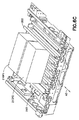
図8を参照すると、開示される実施形態の態様に従って保管および取出システムの一部が示される。この態様では、保管棚800、800Aは、(たとえば、ローバーのフィンガ201がピックフェース支持部300Sの直立部の間に延びている棚300と比較して)略平面状のピックフェース支持表面800Sを有する略平面状の棚である。略平面状のピックフェース支持表面800Sは、ピックフェースの防スナッグ(snag-proof)保管のために(たとえば、収縮包装またはケースユニット自体が棚上で引っかからない)、および流体が棚を通過可能となるように構成され得る。理解できるように、棚を通過する流体を集め、流体が棚800(および棚300)の下にある他の保管レベルに設置されたケースユニットまたはピックフェースに接触するのを実質的に防ぐために、任意の適切な滴下トレイDTが棚800(および棚300)の下に配置されてもよい。この態様の保管棚において、ローバー110Aは、上述のローバー110に実質的に類似しているが、この態様のローバー110Aは、ピックフェースの対向する側面を把持し、ピックフェースを積載ベッド200へおよび積載ベッド200から移送するように構成されるブレード811、812を含むブレード付エンドエフェクタ810を含む。以下においてより詳細に記載される。
Referring to FIG. 8, a portion of a storage and retrieval system is shown in accordance with aspects of the disclosed embodiment. In this embodiment, the
図10A、10B、10Cおよび11を参照すると、保管棚800は、取り出し通路130A(図1)の数の減少、移送デッキ(図1)のサイズの減少を可能にするローバーの全長の減少、およびデッキ(たとえば、移送デッキ130Bおよび取り出し通路デッキADの両方)の数の減少を可能にする。棚800の構成が水平方向および垂直方向のケースの密度の増加も可能にすると同時に、ブレード811、812を用いてケースユニットまたはピックフェースの位置決め/位置合せは、ピックフェースを互いにより近くへ移動させることを可能にする(たとえば、上述のようにピックフェースの間隔を減少させる)。1つまたは複数のケースユニット、またはピックフェースを保管棚へ、または保管棚から移送するためにブレードが使用される場合、ケースユニット間の間隔は、ブレード811、812を、隣接するケースユニットまたはピックフェース間に挿入させるための空間を与えることを注意すべきである。
Referring to FIGS. 10A, 10B, 10C, and 11,
ある態様では、棚800は、たとえば、プレス加工された鋼板または任意の適切な方法で形成された他の任意の適切な材料で構築されてもよい。棚800は、任意の適切な下向きの補剛リブ/補剛突出部800Rを含み、取り出し通路レール130R1、130R2の間の「デッドスペース」(さもなければ、たとえば保管に適していない空間)を活用し得る(取り出し通路レール130R1、130R2は、ローバーが上を走行する取り出し通路デッキ130ADを形成し、一方では、2つの個別のレール130R1、130R2は取り出し通路130Aの両側に示され、他の態様では、取り出し通路デッキは、一体型デッキ部材または取り出し通路130Aの全幅に広がる他の任意の適切な構造であってもよい)。他の態様では、棚は補剛リブを有しなくてもよい。補剛リブ800Rは、流体が棚800を通過可能なように、底部に開口10000を含んでもよい。棚800の開口10000は、ピックフェースが棚800へおよび棚800から移送される方向(矢印11002)に方向付けおよび整列され、略平面状のピックフェース支持表面800Sによる滑らかな角部の移行を含み得る。補剛リブ800Rは任意の適切な形状およびサイズを有し得る。ある態様では、たとえば、棚800を顧客の場所へ、および/または任意の適切な場所における棚800の保管のために移送する間(図10C)、補剛リブは、棚800を積み重ねることが可能な形状であってもよい。棚800は保管ラック構造11005および/または取り出し通路デッキ130AD/レール130R1、130R2に任意の適切な方法で固定され得る(図11)ことに注意すべきである。ある態様では、棚800は、取り外し可能の留め具を用いて、保管ラック構造11005および/または取り出し通路デッキ130AD/レール130R1、130R2に、取り外し可能に固定されてもよい(図11)。他の態様では、棚800は取り外しできなくてもよい。
In an aspect, the
図11を参照すると、別の態様においては、棚800Aはワイヤで構築されてもよい(ワイヤ棚)。ワイヤ棚800Aは、ピックフェースが棚800Aへおよび棚800Aから移送される方向(矢印11002)にワイヤ棚800Aの上部部材800AUが方向付けおよび整列されるワイヤメッシュ構成のような、任意の適切な構成を有し得る。ワイヤ棚800Aは、保管ラック構造11005および/または取り出し通路デッキ/レール130AD、130R1、130R2に任意の適切な方法で固定され得る。ある態様では、図11に示されるように、ワイヤ棚800Aは、保管ラック構造11005および/または取り出し通路デッキ/レール130AD、130R1、130R2に巻き付いてもよく、それにより、ワイヤ棚800Aは、実質的に留め具または他の固定手段(たとえば、接着剤、溶接など)無しで、保管ラック構造11005および/または取り出し通路デッキ/レール130AD、130R1、130R2に取外し可能に固定される。他の態様では、ワイヤ棚800Aは、任意の取外し可能な留め具を用いて、保管ラック構造11005および/または取り出し通路デッキ/レール130AD,130R1、130R2に取外し可能に固定されてもよい。他の態様では、棚800Aは取外し可能でなくてもよい。
Referring to FIG. 11, in another aspect, shelf 800A may be constructed of wires (wire shelf). The wire shelf 800A may be any suitable configuration, such as a wire mesh configuration in which the upper member 800AU of the wire shelf 800A is oriented and aligned in the direction in which the pick face is transferred to and from the shelf 800A (arrow 11002). Can have. The wire shelf 800A may be secured to the
上述のように、保管棚800、800Aは、図10Bに示されるように、互いの上に積み重ねられてもよい。2つの保管棚800V1、800V2が、互いの上に積み重ねられ単一の取り出し通路デッキ130ADからアクセス可能である。他の態様では、単一の取り出し通路デッキ130ADからアクセス可能である2つより多くの保管棚が積み重ねられてもよい。
As described above,
次に図9、図9A、図9B、図9C、および図9Dを参照すると、上に指摘したように、ローバー110Aは、ピックフェースの対向する側面を把持し、ピックフェースを積載ベッド200Aへまたは積載ベッド200Aから移送するように構成されたブレード811、812を含むブレード付エンドエフェクタ810を含む。ブレード811、812は、少なくともブレード811、812の1つを矢印999(図9)の方向の縦方向に移動させるため、ピックフェースの側面を静電力および/または摩擦力によって把持するため(図8および図9A〜図9D)、上述のものに実質的に類似の、駆動部に接続され得る。ブレード811、812のそれぞれが、任意の適切な数のブレード部材BM1、BM2を含む伸縮ブレードであり、それぞれのブレード811、812の伸長および退縮のため、少なくとも1つのブレード部材BM1が、もう1つのブレード部材BM2に、ブレードの伸長軸に沿ってスライド可能に連結される。静電および/または摩擦表面811P、812Pは、ピックフェースを係合させるためそれぞれのブレード部材BM1に固定され得る。他の態様では、各ブレードは固定された(たとえば、非伸縮ブレード)、または他の任意の適切な、エンドエフェクタ部材であってもよい。ブレード部材BM1,BM2は、(たとえば、ローバーの横方向軸に沿った)矢印899の方向にブレードを駆動および伸長するために、任意の適切な駆動部に接続され得る。
Referring now to FIGS. 9, 9A, 9B, 9C, and 9D, as pointed out above, the
ローバー110Aはまた、(一方側のブレードが固定され、他方側のブレードが移動可能である場合、または、両方のブレードが、上述の方法に実質的に類似の方法で移動可能である)動作式の側面揃え、およびケースの境界の物理的確認のための適切なセンサ950(図9C)を含んでもよい。センサ950は、ボットの側面ブレードに設置されたビームライン式またはカーテン式センサであってもよい。センサ950により、ローバーは、ピックフェースを配置する際に、たとえば、保管棚800、800Aのような、ピックフェースのための任意の適切なピックフェース保有場所に存在する、空所の十分な空間を確認することが可能となり、また、ピックフェースが正確な後退(たとえば、ピックフェース保有場所または他の任意の適切な基準面の、取り出し通路エッジからピックフェースが位置する距離)で配置されることを確認することが可能となる。取り出しの際、センサ950は、ケースの標的化およびブレードが保管場所へと伸長する深さの確認を可能にし得る。ブレード811、812は、ピックフェースが保管場所の深い場所に(たとえば、保管棚800、800Aのエッジから遠い保管場所で)配置される時のための案内も行い得る。
ローバー110Aの積載ベッド200Aは、ピックフェース210(およびピックフェースを形成するケースユニット)の、積載ベッド200Aの表面に沿った多自由度のスライド移動を可能とするように構成されてもよい。ある態様では、積載ベッドは、低摩擦係数を有する、任意の適切な材料で構築された略平面状の表面であってもよい。他の態様では、積載ベッドは、上にピックフェースが乗る、複数のボールベアリングを含んでもよい。さらに他の態様では、積載ベッド200Aは、ピックフェース210(およびピックフェースを形成するケースユニット)の、積載ベッド200Aの表面に沿った多自由度のスライド移動を可能とするような任意の適切な構成を有してもよい。
The
図9A〜図9Dを参照して、ピックフェースの、たとえば、保管棚800のような、ピックフェース保有場所の間の移送を説明する。ローバー110Aは取り出し通路130Aに進入し、所定の保管場所で停止する(図17、ブロック1700)。ブレード811、812の1つまたは複数を縦方向に移動させ、ブレードを、たとえば、ピックフェース210の幅に応じた保管場所に整列させる(図9A)ために、ローバー制御装置110Cはエンドエフェクタ駆動部を操作し得る。ローバー制御装置110Cは、ブレードがピックフェース210の側面をまたぐように、ブレード811、812を保管場所の中へ伸長させる(図9B)(図17、ブロック1701)ために駆動部を操作し得る。ブレード811、812が保管場所にどれだけ深く伸長しているかを判定し、ピックフェースまたは(1つまたは複数の)ピックフェースの少なくとも一部を形成するケースユニットの前端および後端の(ブレードの伸長方向に対する)境界を決定する(図9C)(図17、ブロック1702)ために、センサ950は、制御装置110Cにフィードバックを提供する。ブレード811、812が、ピックフェース210に対し、所定の位置に位置すると、ブレードは、たとえば、力フィードバックを用いる上述の方法と実質的に類似の方法で、ピックフェース210(または、ピックフェースの少なくとも一部を形成する1つまたは複数のケースユニット)と係合する、あるいは把持するために縦方向に移動し得る(図17、ブロック1703)。ピックフェース210またはピックフェースの少なくとも一部を形成する(1つまたは複数の)ケースユニットを保管場所から取り出す(図17、ブロック1704)ために、積載ベッド200Aの支持表面は、ピックフェース保管棚800の支持表面と実質的に同じ高さ、または、ブレード811、812が退縮するとブレード811、812に把持されているピックフェース210が保管棚800から積載ベッド200Aの上に滑り落ちるように、より低く位置決めされ得る。ここで、ブレード811、812はピックフェース210を持ち上げなくてもよく、むしろ、ブレード811、812は、ピックフェース210を保管棚800および/または積載ベッド200Aの表面に沿ってスライドさせ得る。他の態様では、ブレード811、812は、保管場所と積載ベッドとの間の移送のためにピックフェースを持ち上げてもよい。なお、積載ベッド200Aが下降することにより、定置フェンス210FEを露出させることができ、定置フェンス210FEは、ピックフェースがローバー110Aにより構築されている場合、ピックフェースを形成するケースユニットは、ブレード811、812を縦方向の位置合せのために用い、寄せ部材110PBおよびフェンス110FEを横方向の位置合せのために用いる、上述の方法と実質的に類似の方法で、フレーム110Fおよび/または自動保管および取出システムの全体の基準フレームに対し、ローバー110Aの積載ベイの内部で、縦方向および横方向に位置合せされ得る(図2)(図17、ブロック1705)という点で、フェンス110FEと実質的に類似であり得る。ピックフェース210の搬送の間、ピックフェースは、ブレード811、812および/または寄せ部材110PBおよびフェンス110FEにより保持され得る。ピックフェース210を任意の適切なピックフェース保有場所に配置するために、ローバー110は、ピックフェース保有場所に対する所定の場所に位置決めされ得る。積載ベッド200Aは、ピックフェース保有場所の支持表面と実質的に同等またはより上のレベルに上昇させられ、ブレード811、812は、ピックフェースを積載ベッド200Aの上に滑り落とすための上述の方法と実質的に類似の方法で、ピックフェース210を積載ベッド200Aからピックフェース保有場所の支持表面の上に滑り落とし得る(図17、ブロック1706)。理解できるように、ローバー110Aへおよびローバー110Aからの積載の移送がピックフェース210に関して記載されるが、上記記載は、ローバー110Aへおよびローバー110Aからの個々のケースユニットの移送にも適用されることを理解すべきである。加えて、保管棚800、800Aに関して言及されるが、ローバーは、ケースユニットおよび/またはケースユニットで形成されるピックフェースを保管棚800、800A、リフト150A、150Bの棚、または他の任意の適切な場所、のような、任意の適切なピックフェース保有場所に移送し得ることを理解すべきである。
With reference to FIGS. 9A-9D, the transfer of pick faces between pick face holding locations, such as
次に図12〜図15を参照して、自動保管および取出システムの一部が、開示される実施形態の態様に従って示されている。この態様では、ローバー110Aは、図10Bに関して上に指摘したように、単一の取り出し通路デッキ130ADV1、130ADV2から、積み重なった保管棚800V1A、800V2A、800V1B、800V2Bにアクセスするように構成される。例示目的だけのため、この態様では、各取り出し通路デッキ130ADV1、130ADV2は保管庫のレベルへのアクセスを提供するが、他の態様では、各取り出し通路は保管庫の2つより多くのレベルへのアクセスを提供してもよい。なお、各取り出し通路によってアクセスされるレベルは、取り出し通路デッキによって変わり得ること(たとえば、あるデッキはいくつかの第1の保管レベルへのアクセスを提供し、一方で、第1とは異なるいくつかの第2の保管レベルへのアクセスを、別のデッキが提供してもよい)。ローバー110Aは、積載ベイ200を持ち上げるまたは下降させる(たとえば、積載ベッド200A、寄せ部材110PBを、図9A〜図9Dに関する上述の方法に実質的に類似の方法で、ケースユニットまたはピックフェースが取り出しまたは配置される保管レベルに対応する所定の高さへ、持ち上げるまたは下降させる)垂直駆動部13000を含んでもよい(図13)。垂直駆動部13000は、積載ベッド200を上昇および下降させるように構成された、たとえば、リニアアクチュエータ、ネジ式駆動、シザーリフト、磁気駆動などのような、任意の適切な駆動部であってよい。別の態様では、ブレード811、812がケースユニットまたはピックフェースを、保管場所への移送のために、積載ベッド200Aから持ち上げる場合、垂直駆動13000は、積載ベッド200Aが垂直方向に固定されたままである一方で、ブレード811、812の垂直移動を引き起こすように構成されてもよい。
With reference now to FIGS. 12-15, a portion of an automated storage and retrieval system is illustrated in accordance with aspects of the disclosed embodiment. In this aspect, the
開示される実施形態の1つまたは複数の態様によると、保管空間のアレイを有する自動保管および取出システムにおいて、少なくとも2つのケースユニットを含むピックフェースを構築する方法が提供される。方法は、ローバーと保管空間のアレイとの間にケースユニットを移送するように構成された自律型ローバーを設けること、ローバーを用いて所定の保管空間から第1のケースユニットを取り出すこと、ローバーを用いて別の所定の保管空間から少なくとも第2のケースユニットを取り出すこと、を含み、第1のケースユニットおよび少なくとも第2のケースユニットがピックフェースを形成し、1単位として搬送される。 According to one or more aspects of the disclosed embodiments, a method for constructing a pick face including at least two case units in an automated storage and retrieval system having an array of storage spaces is provided. The method includes providing an autonomous row bar configured to transfer a case unit between the row bar and an array of storage spaces, using the row bar to remove the first case unit from a predetermined storage space, And taking out at least the second case unit from another predetermined storage space, and the first case unit and at least the second case unit form a pick face and are transported as one unit.
開示される実施形態の1つまたは複数の態様によると、所定の保管空間および別の所定の保管空間は、上下に積み重ねられた棚の上に配置される。 According to one or more aspects of the disclosed embodiment, the predetermined storage space and another predetermined storage space are disposed on a shelf that is stacked up and down.
開示される実施形態の1つまたは複数の態様によると、自律型ローバーが設けられる。自律型ローバーは、第1の端部および第1の端部から縦方向に離間した第2の端部を有し、ピックフェースを支持するようにサイズ決めされる積載ベイを形成するフレームと、ピックフェースに係合するように構成された共通の動作式位置合せ表面と、共通の動作式位置合せ表面に接続された駆動部とを備え、駆動部が、ピックフェースが少なくとも1つの保管棚に沿って、ピックフェース間の所定の保管間隔を有して、実質的に連続的に配列されるように、保管棚上へのピックフェースの配置を実行するために、自動保管および取出システムの少なくとも1つの保管棚に対して、共通動作式位置合せ表面を可変的に位置決めするように構成されている。 According to one or more aspects of the disclosed embodiments, an autonomous rover is provided. The autonomous rover has a first end and a second end vertically spaced from the first end, and a frame forming a loading bay sized to support the pick face; A common operative alignment surface configured to engage a pick face and a drive connected to the common operative alignment surface, the drive having the pick face on at least one storage shelf At least of an automatic storage and retrieval system for performing the placement of pick faces on a storage shelf so that they are arranged substantially continuously with a predetermined storage spacing between the pick faces. A common motion alignment surface is variably positioned with respect to one storage shelf.
開示される実施形態の1つまたは複数の態様によると、所定の保管間隔は、割当てられた保管空間への、および割当てられた保管空間からの、ピックフェースの接触しない挿入または取出を可能とするのに十分な、隣接するピックフェース間の間隙のみを含む。 In accordance with one or more aspects of the disclosed embodiment, the predetermined storage interval allows for non-contact insertion or removal of the pick face into and out of the assigned storage space. Only the gap between adjacent pick faces is sufficient.
開示される実施形態の1つまたは複数の態様によると、自律型ローバーは、ピックフェースを構築するために、少なくとも1つの保管棚の、1つまたは複数の保管場所から、1つまたは複数の物品を取り出すように構成される。 In accordance with one or more aspects of the disclosed embodiment, the autonomous rover is configured to construct one or more items from one or more storage locations of at least one storage shelf to construct a pick face. Configured to take out .
開示される実施形態の1つまたは複数の態様によると、少なくとも1つの保管棚は積み重ねられた保管棚を備え、自律型ローバーが、ピックフェースを構築するために、積み重ねられた保管棚の1つまたは複数の保管場所から、1つまたは複数の物品を取り出すように構成される。 According to one or more aspects of the disclosed embodiments, the at least one storage shelf comprises a stacked storage shelf, and the autonomous rover is one of the stacked storage shelves to build a pick face. Or it is configured to remove one or more items from a plurality of storage locations.
開示される実施形態の1つまたは複数の態様によると、自律型ローバーが設けられる。自律型ローバーは、第1の端部、および第1の端部から縦方向に離間した第2の端部を有し、ピックフェースを支持するようにサイズ決めされる積載ベイを形成するフレームと、ピックフェースに係合するように構成された共通の動作式位置合せ表面と、共通の動作式位置合せ表面に接続された駆動部とを備え、駆動部が少なくともフレームに対して、共通の動作式位置合せ表面を可変的に位置決めするように構成される。 According to one or more aspects of the disclosed embodiments, an autonomous rover is provided. The autonomous rover has a first end and a frame having a second end vertically spaced from the first end and forming a loading bay sized to support the pick face; A common operative alignment surface configured to engage the pick face and a drive connected to the common operative alignment surface, wherein the drive is at least common to the frame It is configured to variably position the formula alignment surface.
開示される実施形態の1つまたは複数の態様によると、共通の動作式位置合せ表面を可変的に位置決めすることが、保管棚上へのピックフェースの配置を実行し、それによって、ピックフェースが棚に沿って、ピックフェース間の所定の保管間隔を有して、実質的に連続的に配列される。 According to one or more aspects of the disclosed embodiments variably positioning a common operative alignment surface performs placement of the pick face on a storage shelf so that the pick face is Along the shelf are arranged substantially continuously with a predetermined storage spacing between the pick faces.
開示される実施形態の1つまたは複数の態様によると、自律型ローバーは、ピックフェースを構築するための、保管棚の、1つまたは複数の保管場所から、1つまたは複数の物品を取り出すように構成される。 According to one or more aspects of the disclosed embodiments, the autonomous rover is adapted to remove one or more items from one or more storage locations of a storage shelf for constructing a pick face. Configured.
開示される実施形態の1つまたは複数の態様によると、1つまたは複数の保管場所が、上下に積み重ねられた保管棚の上に設置される。 According to one or more aspects of the disclosed embodiments, one or more storage locations are installed on storage shelves that are stacked one above the other.
開示される実施形態の1つまたは複数の態様によると、自律型ローバーはさらに、共通の動作式位置合せ表面の、積載ベイに対する平均位置が、積載ベイ内のピックフェースの所定の位置と実質的に一致するように、共通の動作式位置合せ表面の移動を実行するために、駆動部に接続された制御装置を含む。 According to one or more aspects of the disclosed embodiments, the autonomous rover further includes an average position of the common motion alignment surface relative to the load bay substantially equal to the predetermined position of the pick face within the load bay. Includes a controller connected to the drive to perform movement of the common operative alignment surface to match.
開示される実施形態の1つまたは複数の態様によると、自律型ローバーはさらに、ピックフェースと係合するための共通の動作式位置合せ表面の移動を実行するように、駆動部に接続された制御装置をさらに備え、制御装置が、共通の動作式位置合せ表面のピックフェースとの係合力を制御するために少なくとも駆動部の電流値を監視するように構成される。他の態様では、制御装置は、係合力を判定するように構成されたカルマンフィルタを含む。 According to one or more aspects of the disclosed embodiment, the autonomous rover is further connected to the drive to perform movement of a common operative alignment surface to engage the pick face. A control device is further included, and the control device is configured to monitor at least the current value of the drive unit to control the engagement force of the common motion alignment surface with the pick face. In another aspect, the control device includes a Kalman filter configured to determine the engagement force.
開示される実施形態の1つまたは複数の態様によると、共通の動作式位置合せ表面は、少なくとも部分的に積載ベイ内に配置された第1の可動部材、および少なくとも部分的に積載ベイ内に配置され、第1の可動部材に対し対向して位置付けられた第2の可動部材と、を含み、駆動部が、第1および第2の可動部材を、互いに向けて、および互いから離れるように、共に縦方向に1単位として、移動させるように構成される。 In accordance with one or more aspects of the disclosed embodiment, the common operative alignment surface includes a first movable member disposed at least partially within the loading bay, and at least partially within the loading bay. A second movable member disposed and positioned opposite to the first movable member, wherein the drive unit directs the first and second movable members toward and away from each other. Both are configured to move as one unit in the vertical direction.
開示される実施形態の1つまたは複数の態様によると、駆動部は、全体的な自動保管および取出基準フレームに対して、共通動作式位置合せ表面を可変的に位置決めするように構成される。 According to one or more aspects of the disclosed embodiment, the drive is configured to variably position the common motion alignment surface relative to the overall automatic storage and retrieval reference frame.
開示される実施形態の1つまたは複数の態様によると、共通の動作式位置合せ表面を可変的に位置決めすることが、フレームからピックフェースの配置を分離させる。 According to one or more aspects of the disclosed embodiment, variably positioning the common motion alignment surface separates the pick face placement from the frame.
開示される実施形態の1つまたは複数の態様によると、ピックフェースは、1単位として共に移動する、少なくとも1つのケースユニットを含む。 According to one or more aspects of the disclosed embodiment the pick face includes at least one case unit that moves together as a unit.
開示される実施形態の1つまたは複数の態様によると、自動保管および取出システムが設けられる。自動保管および取出システムは、保管場所のアレイと、保管場所のアレイと連絡している少なくとも1つの自律型ローバーとを備えた自動保管および取出システムであって、少なくとも1つの自律型ローバ―が、第1の端部、および第1の端部から縦方向に離間した第2の端部を有し、ピックフェースを支持するようにサイズ決めされる積載ベイを形成する、フレームと、ピックフェースに係合するように構成された共通の動作式位置合せ表面と、共通の動作式位置合せ表面に接続された駆動部とを含み、駆動部は、少なくともフレームに対して共通の動作式位置合せ表面を可変的に位置決めするように構成される。 According to one or more aspects of the disclosed embodiment an automatic storage and retrieval system is provided. An automatic storage and retrieval system is an automatic storage and retrieval system comprising an array of storage locations and at least one autonomous rover in communication with the storage location array, wherein at least one autonomous rover is A frame having a first end and a second end longitudinally spaced from the first end, and forming a stacking bay sized to support the pick face; A common operative alignment surface configured to engage and a drive connected to the common operative alignment surface, wherein the drive is at least a common operative alignment surface for the frame Are configured to be variably positioned.
開示される実施形態の1つまたは複数の態様によると、共通の動作式位置合せ表面を可変的に位置決めすることが、保管場所のアレイの保管棚上へのピックフェースの配置を実行し、それによって、ピックフェースが棚に沿って、ピックフェース間の所定の保管間隔を有して、実質的に連続的に配列される。 According to one or more aspects of the disclosed embodiments, variably positioning a common operative alignment surface performs placement of pick faces on storage shelves of an array of storage locations, The pick faces are arranged substantially continuously along the shelf with a predetermined storage interval between the pick faces.
開示される実施形態の1つまたは複数の態様によると、自律型ローバーは、ピックフェースを構築するために、1つまたは複数の保管場所から、1つまたは複数の物品を取り出すように構成される。 According to one or more aspects of the disclosed embodiment, the autonomous rover is configured to remove one or more items from one or more storage locations to construct a pick face. .
開示される実施形態の1つまたは複数の態様によると、少なくとも1つの自律型ローバーはさらに、共通の動作式位置合せ表面の積載ベイに対する平均位置が積載ベイ内のピックフェースの所定の位置と実質的に一致するように、共通の動作式位置合せ表面の移動を実行するために、駆動部に接続された制御装置を含む。 According to one or more aspects of the disclosed embodiments, the at least one autonomous rover is further configured such that an average position of the common operative alignment surface relative to the load bay is substantially equal to a predetermined position of the pick face within the load bay. A controller connected to the drive to perform the movement of the common operative alignment surface to be consistent with each other.
開示される実施形態の1つまたは複数の態様によると、ピックフェースと係合するための共通の動作式位置合せ表面の移動を、実行するように、少なくとも1つの自律型ローバーは駆動部に接続された制御装置をさらに備え、制御装置は、共通の動作式位置合せ表面のピックフェースとの係合力を制御するために、少なくとも駆動部の電流値を監視するように構成される。他の態様では、制御装置は、係合力を判定するように構成されたカルマンフィルタを含む。 In accordance with one or more aspects of the disclosed embodiment, the at least one autonomous rover is connected to the drive so as to perform a movement of the common operative alignment surface to engage the pick face The controller is configured to monitor at least the current value of the drive to control the engagement force of the common operative alignment surface with the pick face. In another aspect, the control device includes a Kalman filter configured to determine the engagement force.
開示される実施形態の1つまたは複数の態様によると、共通の動作式位置合せ表面は、少なくとも部分的に積載ベイ内に配置された第1の可動部材と、少なくとも部分的に積載ベイ内に配置され、第1の可動部材に対して対向に位置付けられた第2の可動部材とを含み、駆動部が、第1および第2の可動部材を、互いに向けて、および互いから離れるように、共に縦方向に1単位として、移動させるように構成される。 According to one or more aspects of the disclosed embodiments, the common operative alignment surface includes a first movable member disposed at least partially within the loading bay and at least partially within the loading bay. A second movable member disposed and positioned opposite to the first movable member, wherein the drive unit directs the first and second movable members toward and away from each other, Both are configured to move as one unit in the vertical direction.
開示される実施形態の1つまたは複数の態様によると、駆動部は、全体的な自動保管および取出基準フレームに対して、共通の動作式位置合せ表面を可変的に位置決めするように構成される。 According to one or more aspects of the disclosed embodiment, the drive is configured to variably position a common operative alignment surface relative to the overall automatic storage and retrieval reference frame. .
開示される実施形態の1つまたは複数の態様によると、共通の動作式位置合せ表面を可変的に位置決めすることが、フレームからピックフェースの配置を分離させる。 According to one or more aspects of the disclosed embodiment, variably positioning the common motion alignment surface separates the pick face placement from the frame.
開示される実施形態の1つまたは複数の態様によると、ピックフェースは、1単位として共に移動する、少なくとも1つのケースユニットを含む。 According to one or more aspects of the disclosed embodiment the pick face includes at least one case unit that moves together as a unit.
開示される実施形態の1つまたは複数の態様によると、自律型ローバーが設けられる。自律型ローバーは、少なくとも1つのケースユニットを支持するようにサイズ決めされる積載ベイを形成するフレームと、少なくとも部分的に積載ベイ内に配置された第1の可動部材と、少なくとも部分的に積載ベイ内に配置され、第1の可動部材に対して対向に位置付けられた第2の可動部材と、フレームに接続され、第1および第2のそれぞれの可動部材用のそれぞれの駆動モータを含む駆動部であって、少なくとも1つのケースユニットを係合させるために、第1および第2の可動部材を、退縮位置および展開位置の間で移動させるように構成された駆動部と、第1および第2の可動部材の移動を実行するために駆動部を少なくとも制御するように構成された制御装置と、を含み、第1および第2の可動部材が、少なくとも1つのケースユニットを把持するように構成され、制御装置が、少なくとも1つのケースユニットの配置がフレームから分離されるように、少なくとも1つのケースユニットの積載ベイ内の可変的な位置決めを実行する。 According to one or more aspects of the disclosed embodiments, an autonomous rover is provided. The autonomous rover includes a frame forming a loading bay that is sized to support at least one case unit, a first movable member disposed at least partially within the loading bay, and at least partially loaded. A second movable member disposed within the bay and positioned opposite to the first movable member; a drive connected to the frame and including respective drive motors for the first and second movable members; A drive unit configured to move the first and second movable members between a retracted position and a deployed position to engage at least one case unit; and first and first And a control device configured to at least control the drive unit to perform movement of the two movable members, wherein the first and second movable members are at least one case. It is configured to grip the unit, control device, as the arrangement of at least one case unit are separated from the frame, to perform the variable positioning of the loading bay at least one case unit.
開示される実施形態の1つまたは複数の態様によると、自律型ローバーはさらに、第1および第2の可動部材の、互いに向けての、および互いから離れる移動を実行するために、駆動部を少なくとも制御するように構成された制御装置を含む。 In accordance with one or more aspects of the disclosed embodiment, the autonomous rover further includes a drive to perform movement of the first and second movable members toward and away from each other. A controller configured to control at least.
開示される実施形態の1つまたは複数の態様によると、自律型ローバーはさらに、第1および第2の可動部材の、積載ベイの全長に沿った、1単位としての移動を実行するために、駆動部を少なくとも制御するように構成された制御装置を含む。 According to one or more aspects of the disclosed embodiment, the autonomous rover is further configured to perform movement of the first and second movable members as a unit along the entire length of the loading bay. A controller configured to at least control the drive;
開示される実施形態の1つまたは複数の態様によると、自律型ローバーはさらに、フレームに接続され、少なくとも1つのケースユニットを、積載ベイへまたは積載ベイから、移送するように構成されたエンドエフェクタを含み、制御装置は少なくとも1つのケースユニットの、エンドエフェクタに対する可変的な位置決めを実行する。他の態様では、フレームは、第1の端部と、第1の端部から縦方向に離間した第2の端部と、を含み、エンドエフェクタは積載ベイに対する横方向移動のために構成され、第1および第2の可動部材は、積載ベイの全長を縦方向に横断するように配列される。 According to one or more aspects of the disclosed embodiment, the autonomous rover is further connected to a frame and is configured to transfer at least one case unit to or from the loading bay. And the controller performs variable positioning of the at least one case unit relative to the end effector. In another aspect, the frame includes a first end and a second end longitudinally spaced from the first end, and the end effector is configured for lateral movement relative to the loading bay. The first and second movable members are arranged to traverse the entire length of the loading bay in the vertical direction.
開示される実施形態の1つまたは複数の態様によると、それぞれの各駆動モータは、それぞれの第1および第2の可動部材に取り付けられ、駆動部は、各駆動モータのそれぞれに連結された共通の駆動部材を含み、共通の駆動部材はフレームに対して移動可能に固定されている。 According to one or more aspects of the disclosed embodiments, each respective drive motor is attached to a respective first and second movable member, and a drive is coupled to each of the respective drive motors in common. The common drive member is fixed to be movable with respect to the frame.
開示される実施形態の1つまたは複数の態様によると、それぞれの各駆動モータはフレームに取り付けられ、駆動部は、それぞれの第1および第2可動部材をそれぞれの駆動モータに連結するために、各モータのそれぞれに接続された個別に移動可能である駆動部材を含む。 According to one or more aspects of the disclosed embodiments, each respective drive motor is attached to a frame, and the drive is configured to couple the respective first and second movable members to the respective drive motor. It includes individually movable drive members connected to each of the motors.
開示される実施形態の1つまたは複数の態様によると、自律型ローバーはさらに、積載表面の下に設置された線形ガイド部材を含み、第1および第2の可動部材は、線形ガイド部材に、および線形ガイド部材からぶら下がって移動可能に取り付けられる。別の態様では、第1および第2の可動部材のそれぞれは、線形ガイド部材から片持ちされる。 According to one or more aspects of the disclosed embodiment, the autonomous rover further includes a linear guide member installed below the loading surface, wherein the first and second movable members are on the linear guide member, And movably mounted hanging from the linear guide member. In another aspect, each of the first and second movable members is cantilevered from the linear guide member.
開示される実施形態の1つまたは複数の態様によると、駆動部は、第1および第2の可動部材のそれぞれを個別に駆動するように構成された、2自由度駆動を備える。 According to one or more aspects of the disclosed embodiment the drive comprises a two degree of freedom drive configured to drive each of the first and second movable members individually.
開示される実施形態の1つまたは複数の態様によると、自律型ローバーの積載ベイ内で少なくとも1つのケースユニットを揃えるための方法が提供され、自律型ローバーは、積載ベイを形成しているフレームと、少なくとも1つのケースユニットを積載ベイへ、および積載ベイから移動させるためのエンドエフェクタと、を含んでいる。この方法は、少なくとも部分的に積載ベイ内にある、第1の可動部材および第2の可動部材を設けることと、少なくとも1つのケースユニットを把持するために、第1および第2の可動部材のそれぞれを個別に駆動することと、少なくとも1つのケースユニットの配置がフレームから分離されるように、少なくとも1つのケースユニットを積載ベイ内で可変的に位置決めするために、少なくとも1つのケースユニットを第1および第2の可動部材を用いて移動させることと、を含む。 According to one or more aspects of the disclosed embodiments, a method is provided for aligning at least one case unit within a loading bay of an autonomous rover, the autonomous rover being a frame forming a loading bay And an end effector for moving the at least one case unit to and from the loading bay. The method includes providing a first movable member and a second movable member that are at least partially within the loading bay, and for gripping the at least one case unit. In order to variably position at least one case unit in the loading bay so that each is driven individually and the arrangement of the at least one case unit is separated from the frame, the at least one case unit is Moving using the first and second movable members.
開示される実施形態の1つまたは複数の態様によると、少なくとも1つのケースユニットは、エンドエフェクタに対して位置決めされる。 According to one or more aspects of the disclosed embodiment at least one case unit is positioned relative to the end effector.
開示される実施形態の1つまたは複数の態様によると、自動保管および取出システムのための自律型ローバーが設けられる。自律型ローバーは、第1の端部および第1の端部から縦方向に離間した第2の端部を有し、積載ベイを形成するフレームと、少なくとも部分的に積載ベイ内に移動可能に取り付けられる積載ベッドであって、積載ベッドが第1の面内を移動可能であり、積載支持表面を横切る、ピックフェースの実質的にスナッギングを起こさない(snagless)スライドを可能にするために、実質的に摩擦の無い積載支持表面を有する積載ベッドと、積載ベッドに移動可能に取り付けられ、フレームに対し横方向に延びるように、そしてピックフェースの対向する側面のみを把持するように構成された第1の把持部材および第2の把持部材とを含み、第1の把持部材および第2の把持部材の少なくとも1つが、積載ベッドに対し縦方向に移動可能であり、第1および第2の把持部材の移動が、第1の面に対して略直交する第2の面に沿っており、第1および第2の把持部材が1単位として積載ベッドとともに、第1の面で移動する。 According to one or more aspects of the disclosed embodiment, an autonomous rover for an automated storage and retrieval system is provided. The autonomous rover has a first end and a second end vertically spaced from the first end, and is movable at least partially within the load bay, with a frame forming the load bay A load bed attached, wherein the load bed is movable in a first plane, substantially to allow a substantially snagless slide of the pick face across the load bearing surface A load bed having a friction-free load support surface, and a movably attached to the load bed, extending laterally with respect to the frame, and configured to grip only opposite sides of the pick face One gripping member and a second gripping member, wherein at least one of the first gripping member and the second gripping member is movable in the vertical direction with respect to the loading bed, And the movement of the second gripping member is along a second surface substantially orthogonal to the first surface, and the first and second gripping members are united with the loading bed as a unit on the first surface. Moving.
開示される実施形態の1つまたは複数の態様によると、第1および第2の把持部材はピックフェースの対向する側面を静電気によって把持するように構成される。 In accordance with one or more aspects of the disclosed embodiment, the first and second gripping members are configured to grip the opposing sides of the pick face electrostatically.
開示される実施形態の1つまたは複数の態様によると、第1および第2の把持部材はピックフェースの対向する側面を摩擦によって把持するように構成される。 In accordance with one or more aspects of the disclosed embodiment, the first and second gripping members are configured to grip opposing sides of the pick face by friction.
開示される実施形態の1つまたは複数の態様によると、自律型ローバーはさらに、第1および第2の把持部材に把持されたピックフェースの、少なくとも1つの境界を検出すること、自律型ローバーにアクセス可能な、略平面状の棚上に存在する所定のサイズの空所の保管空間を確認すること、ピックフェースが略平面状の保管棚上に、所定の後退を有して配置されることを確認すること、第1および第2の把持部材が略平面状の保管棚の保管場所へと延びる距離を確認すること、および、ピックフェースを略平面状の保管棚の保管場所へ配置するための案内を行うことのうち、少なくとも1つを行うように構成された、少なくとも1つのセンサを含む。別の態様では、少なくとも1つのセンサが、第1および第2の把持部材の少なくとも1つに設置される。 According to one or more aspects of the disclosed embodiment, the autonomous rover is further capable of detecting at least one boundary of the pick face gripped by the first and second gripping members, Check for a storage space of a predetermined size that is accessible on a substantially planar shelf, and that the pick face is placed on the substantially planar storage shelf with a predetermined retraction. Confirming the distance that the first and second gripping members extend to the storage location of the substantially planar storage shelf, and disposing the pick face to the storage location of the approximately planar storage shelf. At least one sensor configured to perform at least one of performing the guidance. In another aspect, at least one sensor is located on at least one of the first and second gripping members.
開示される実施形態の1つまたは複数の態様によると、フレームは側面フェンスを含み、積載ベッドは、側面フェンスを実質的に摩擦の無い積載支持表面上に設置されたピックフェースに露出させるために、フレームに対し移動するように構成されている。 According to one or more aspects of the disclosed embodiment the frame includes a side fence and the load bed is exposed to a pick face installed on a load bearing surface that is substantially friction-free. , Configured to move relative to the frame.
開示される実施形態の1つまたは複数の態様によると、自動保管および取出システムは、
略平面状の保管棚および、隣接する略平面状の保管棚の間に設置された少なくとも1つのローバー支持表面を有する保管構造であって、それぞれの保管棚が、ピックフェース支持表面を横切る、ピックフェースのスナッギングを起こさないピスライドを可能とするように構成された、実質的にスナッギングを起こさないピックフェース支持表面を有している、保管構造と;
少なくとも1つのローバー支持表面を横断するように構成されたフレーム、フレームに移動可能に取り付けられた積載ベッド、および、積載ベッドに移動可能に取り付けられた把持部材を有する自律型ローバーであって、積載ベッドが、実質的に摩擦の無い積載支持表面を横切る、ピックフェースのスライドを可能にするように構成された、実質的に摩擦の無い積載支持表面を有し、把持部材が、ピックフェースの対向する側面のみを把持するように構成されている、自律型ローバーと;
を含み、実質的に摩擦の無い積載支持表面と、実質的にスナッギングを起こさないピックフェース支持表面との間で、ピックフェースのスライド移送のために、把持部材はフレームに対し少なくとも2自由度で移動可能である。
According to one or more aspects of the disclosed embodiments an automatic storage and retrieval system comprises:
Picks having a substantially planar storage shelf and at least one row bar support surface disposed between adjacent substantially planar storage shelves, each storage shelf crossing a pick face support surface A storage structure having a substantially non-snugging pickface support surface configured to allow pislide that does not cause snagging of the face;
An autonomous row bar having a frame configured to traverse at least one row bar support surface, a load bed movably attached to the frame, and a gripping member movably attached to the load bed, wherein The bed has a substantially friction-free loading support surface configured to allow sliding of the pick face across a substantially friction-free loading support surface and the gripping member is opposite the pick face. An autonomous rover configured to grip only the side to be
The gripping member has at least two degrees of freedom relative to the frame for slide transfer of the pick face between a substantially friction-free loading support surface and a pick face support surface that does not substantially snuggle. It is movable.
開示される実施形態の1つまたは複数の態様によると、積載ベッドは第1の面で移動し、把持部材は第1の面に直交する第2の面で移動する。 According to one or more aspects of the disclosed embodiments the loading bed moves on a first surface and the gripping member moves on a second surface orthogonal to the first surface.
開示される実施形態の1つまたは複数の態様によると、把持部材は、縦方向に移動可能な把持部材および、ピックフェースをフレームに対して揃えるように構成された定置把持部材を備える。 According to one or more aspects of the disclosed embodiment the gripping member comprises a gripping member that is movable in the longitudinal direction and a stationary gripping member configured to align the pick face with respect to the frame.
開示される実施形態の1つまたは複数の態様によると、把持部材はピックフェースの対向する側面を静電気によって把持するように構成される。 According to one or more aspects of the disclosed embodiment the gripping member is configured to grip the opposing sides of the pick face with static electricity.
開示される実施形態の1つまたは複数の態様によると、把持部材はピックフェースの対向する側面を摩擦によって把持するように構成される。 According to one or more aspects of the disclosed embodiment the gripping member is configured to grip the opposing sides of the pick face by friction.
開示される実施形態の1つまたは複数の態様によると、略平面状の保管棚は、流体が略平面状の保管棚を通過可能となるように構成される。別の態様では、略平面状の保管棚は補剛リブを通過している。さらに別の態様では、略平面状の保管棚はワイヤ棚からなる。さらに別の態様では、流体閉込トレイが少なくとも1つの略平面状の保管棚の下に配置される。 According to one or more aspects of the disclosed embodiment the substantially planar storage shelf is configured to allow fluid to pass through the substantially planar storage shelf. In another aspect, the substantially planar storage shelf passes through the stiffening ribs. In yet another aspect, the substantially planar storage shelf comprises a wire shelf. In yet another aspect, a fluid confinement tray is disposed under at least one substantially planar storage shelf.
開示される実施形態の1つまたは複数の態様によると、自律型ローバーは、
把持部材に把持されたピックフェースの少なくとも1つの境界を検出すること、
略平面状の棚上に存在する所定のサイズの空所の保管空間を確認すること、
ピックフェースが略平面状の保管棚上に、所定の後退を有して、配置されることを確認すること、
把持部材が略平面状の保管棚の保管場所へと延びる距離を確認すること、および
ピックフェースを略平面状の保管棚の保管場所へ配置するための案内を行うことのうち、少なくとも1つを行うように構成された、少なくとも1つのセンサを含む。ある態様では、少なくとも1つのセンサが、少なくとも1つの把持部材に設置される。
According to one or more aspects of the disclosed embodiment, the autonomous rover is
Detecting at least one boundary of the pick face gripped by the gripping member;
Check the storage space of a predetermined size of space on a substantially flat shelf,
Confirming that the pick face is placed on a substantially planar storage shelf with a predetermined retraction;
At least one of confirming the distance the gripping member extends to the storage location of the substantially planar storage shelf and providing guidance for placing the pick face to the storage location of the substantially planar storage shelf Including at least one sensor configured to perform. In some embodiments, at least one sensor is installed on at least one gripping member.
開示される実施形態の1つまたは複数の態様によると、フレームは、側面フェンスを含み、積載ベッドが、側面フェンスを実質的に摩擦の無い積載支持表面上に設置されたピックフェースに露出させるために、フレームに対し移動するように構成されている。 According to one or more aspects of the disclosed embodiment the frame includes a side fence so that the loading bed exposes the side fence to a pick face installed on a substantially friction-free loading support surface. In addition, it is configured to move relative to the frame.
開示される実施形態の1つまたは複数の態様によると、略平面状の保管棚は、垂直方向に離間した複数の保管棚を備え、少なくともローバー支持表面は、自律型ローバーに単一のローバー支持表面から、少なくとも2つの垂直方向に離間した保管棚へのアクセスを提供するため、積載ベッドがフレームに対して移動可能である、垂直方向に離間した複数のローバー支持表面を備える。 According to one or more aspects of the disclosed embodiments, the substantially planar storage shelf comprises a plurality of vertically spaced storage shelves, wherein at least the row bar support surface is a single row bar support for the autonomous row bar. To provide access from the surface to at least two vertically spaced storage shelves, the load bed includes a plurality of vertically spaced rover support surfaces that are movable relative to the frame.
上記記載は、開示された実施形態の態様を例示するだけであることを理解すべきである。様々な代替および変更が、開示される実施形態の態様から逸脱することなく、当業者によって案出されうる。従って、開示された実施形態は、付加されたクレームの範囲に該当するそのような代替、変更、および変形の全てを包含することを意図している。さらに、単に、異なる特徴が相互に異なる従属クレームまたは独立クレーム内に列挙されるという事実は、これらの特徴の組み合わせは有利に使用することができないということは意味せず、そのような組み合わせは本発明の態様の範囲内に留まる。 It should be understood that the above description is only illustrative of aspects of the disclosed embodiments. Various alternatives and modifications can be devised by those skilled in the art without departing from the aspects of the disclosed embodiments. Accordingly, the disclosed embodiments are intended to embrace all such alterations, modifications and variations that fall within the scope of the appended claims. Furthermore, the fact that different features are recited in mutually different dependent or independent claims does not mean that a combination of these features cannot be used to advantage, and such a combination is not It remains within the scope of the invention.
Claims (28)
保管空間のアレイを有する自動保管および取出システムに、少なくとも2つのケースユニットを提供することと、
自律型ローバーエンドエフェクタを用いて、ローバーと前記保管空間のアレイとの間にケースユニットを移送するように構成された自律型ローバーを設けることと、
前記自律型ローバーエンドエフェクタを用いて、所定の保管空間から第1のケースユニットを取り出すことと、
前記自律型ローバーエンドエフェクタおよび前記第1のケースユニットを保持する前記自律型ローバーエンドエフェクタを用いて、別の所定の保管空間から少なくとも第2のケースユニットを取り出すことと、を含み、
前記自律型ローバーエンドエフェクタを用いて取り出された前記第1のケースユニットおよび前記少なくとも第2のケースユニットが、前記第1のケースユニットを保持する前記自律型ローバーエンドエフェクタを用いて前記少なくとも第2のケースユニットを取り出す際に前記ピックフェースを形成し、1単位として搬送され、前記第1のケースユニットおよび前記少なくとも第2のケースユニットが、前記ピックフェース内で互いに対して相補的である、
方法。 A method of constructing a pick face,
Providing at least two case units for an automated storage and retrieval system having an array of storage spaces;
Providing an autonomous rover configured to transfer a case unit between the rover and the array of storage spaces using an autonomous rover end effector ;
Using the autonomous rover end effector to remove the first case unit from a predetermined storage space;
Using said autonomous rover end effector for holding the autonomous rover end effector and said first case unit includes a taking out at least a second case unit from another predetermined storage space,
The first case unit and the at least second case unit that are taken out using the autonomous type rover end effector use the autonomous type rover end effector that holds the first case unit. the pick face formed when retrieving casing unit, is conveyed as a unit, the first casing unit and the at least second case unit, Ru complementary der respect to each other within the pick face,
Method.
第1の端部、および前記第1の端部から縦方向に離間した第2の端部を有し、ピックフェースを支持するようにサイズ決めされる積載ベイを形成するフレームと、
前記ピックフェースに係合するように構成された共通の動作式位置合せ表面と、
前記共通の動作式位置合せ表面に接続された駆動部と
を備え、
前記駆動部が、ピックフェースが少なくとも1つの保管棚に沿って、前記ピックフェース間の所定の保管間隔を有して、実質的に連続的に配列されるように、前記少なくとも1つの保管棚上への前記ピックフェースの配置を実行するために、前記少なくとの1つの保管棚に対して前記ピックフェースを位置合せする前記共通の動作式位置合せ表面を、自動保管および取出システムの前記少なくとも1つの保管棚に対して可変的に位置決めするように構成され、位置合せが、前記ピックフェースに係合する前記共通の動作式位置合せ表面の可変位置に基づいている、
自律型ローバー。 An autonomous rover,
First end and a second end spaced longitudinally from the first end, and a frame that form a loading bay that is sized to support the pick face,
A common operative alignment surface configured to engage the pick face;
A drive connected to the common motion alignment surface;
The drive is on the at least one storage shelf such that the pick faces are arranged substantially continuously along the at least one storage shelf with a predetermined storage interval between the pick faces. The common operational alignment surface for aligning the pick face with respect to the at least one storage shelf for performing the placement of the pick face on the at least one of the automatic storage and removal systems. One of the relative storage shelf is configured to position variable manner, the alignment is based on the variable position of said common-operated alignment surface for engaging the pick face,
Autonomous rover.
第1の端部、および前記第1の端部から縦方向に離間した第2の端部を有し、ピックフェースを支持するようにサイズ決めされる積載ベイを形成するフレームと、
前記ピックフェースに係合するように構成された共通の動作式位置合せ表面と、
前記共通の動作式位置合せ表面に接続された駆動部とを備え、
前記駆動部が、ピックフェースが保管棚に沿って、前記ピックフェース間の所定の保管間隔を有して、実質的に連続的に配列されるように、前記保管棚上への前記ピックフェースの配置を実行し、前記保管棚に対して前記ピックフェースを位置合せするために、少なくとも前記フレームに対して、前記共通の動作式位置合せ表面を可変的に位置決めするように構成され、位置合せが、前記ピックフェースに係合する前記共通の動作式位置合せ表面の可変位置に基づいている、
自律型ローバー。 An autonomous rover,
First end and a second end spaced longitudinally from the first end, and a frame that form a loading bay that is sized to support the pick face,
A common operative alignment surface configured to engage the pick face;
A drive connected to the common motion alignment surface;
The drive is arranged such that the pick faces are arranged on the storage shelf substantially continuously along the storage shelf with a predetermined storage interval between the pick faces. run the arrangement, in order to align the pick face to the storage shelf, with respect to at least the frame, is composed of the common-operated positioning surface to variably positioning and alignment Based on the variable position of the common operative alignment surface engaging the pick face ;
Autonomous rover.
少なくとも部分的に前記積載ベイ内に配置された第1の可動部材、および
少なくとも部分的に前記積載ベイ内に配置され、前記第1の可動部材に対して対向して位置付けられた第2の可動部材を含み、
前記駆動部が、前記第1および第2の可動部材を、互いに向けて、および互いから離れるように、共に縦方向に1単位として、移動させるように構成される、請求項7記載の自律型ローバー。 The common operative alignment surface;
A first movable member disposed at least partially within the loading bay, and a second movable member disposed at least partially within the loading bay and positioned opposite the first movable member. Including members,
The autonomous type according to claim 7, wherein the driving unit is configured to move the first and second movable members toward and away from each other as a unit in the longitudinal direction. Rover.
前記保管場所のアレイと連絡している少なくとも1つの自律型ローバーとを備えた自動保管および取出システムであって、
前記少なくとも1つの自律型ローバーが
第1の端部、および前記第1の端部から縦方向に離間した第2の端部を有し、ピックフェースを支持するようにサイズ決めされる積載ベイを形成するフレームと、
前記ピックフェースに係合するように構成された共通の動作式位置合せ表面と、
前記共通の動作式位置合せ表面に接続された駆動部とを含み、
前記駆動部が、ピックフェースが保管棚に沿って、前記ピックフェース間の所定の保管間隔を有して、実質的に連続的に配列されるように、少なくとも前記フレームに対して前記共通の動作式位置合せ表面を可変的に位置決めし、前記保管棚上への前記ピックフェースの配置を実行し、前記保管場所のアレイの前記保管棚に対して前記ピックフェースを位置合せするように構成され、位置合せが、前記ピックフェースに係合する前記共通の動作式位置合せ表面の可変位置に基づいている、
自動保管および取出システム。 An array of storage locations;
An automatic storage and retrieval system comprising at least one autonomous rover in communication with the array of storage locations,
A stacking bay, wherein the at least one autonomous row bar has a first end and a second end vertically spaced from the first end, and is sized to support a pick face; A frame to be formed;
A common operative alignment surface configured to engage the pick face;
A drive connected to the common operative alignment surface;
The common operation of at least the frame is such that the drive is arranged substantially continuously along the storage shelf with a predetermined storage interval between the pick faces. Variably positioning a formula alignment surface, performing placement of the pick face on the storage shelf, and aligning the pick face with respect to the storage shelf of the array of storage locations ; Alignment is based on a variable position of the common operative alignment surface that engages the pick face .
Automatic storage and retrieval system.
少なくとも部分的に前記積載ベイ内に配置された第1の可動部材と、
少なくとも部分的に前記積載ベイ内に配置され、前記第1の可動部材に対して対向に位置付けられた第2の可動部材と、を含み、
前記駆動部が、前記第1および第2の可動部材を、互いに向けて、および互いから離れるように、共に縦方向に1単位として、移動させるように構成される、請求項16記載の自動保管および取出システム。 The common operative alignment surface;
A first movable member disposed at least partially within the loading bay;
A second movable member disposed at least partially within the loading bay and positioned opposite to the first movable member;
17. The automatic storage according to claim 16, wherein the driving unit is configured to move the first and second movable members toward and away from each other as a unit in the longitudinal direction. And take-off system.
Applications Claiming Priority (5)
| Application Number | Priority Date | Filing Date | Title |
|---|---|---|---|
| US201361790801P | 2013-03-15 | 2013-03-15 | |
| US61/790,801 | 2013-03-15 | ||
| US14/215,310 | 2014-03-17 | ||
| US14/215,310 US9802761B2 (en) | 2013-03-15 | 2014-03-17 | Automated storage and retrieval system |
| PCT/US2014/030217 WO2014145450A1 (en) | 2013-03-15 | 2014-03-17 | Automated storage and retrieval system |
Related Child Applications (1)
| Application Number | Title | Priority Date | Filing Date |
|---|---|---|---|
| JP2018212524A Division JP6765404B2 (en) | 2013-03-15 | 2018-11-12 | Automatic storage and retrieval system |
Publications (3)
| Publication Number | Publication Date |
|---|---|
| JP2016512806A JP2016512806A (en) | 2016-05-09 |
| JP2016512806A5 JP2016512806A5 (en) | 2018-07-19 |
| JP6435316B2 true JP6435316B2 (en) | 2018-12-05 |
Family
ID=51531427
Family Applications (2)
| Application Number | Title | Priority Date | Filing Date |
|---|---|---|---|
| JP2016503353A Active JP6435316B2 (en) | 2013-03-15 | 2014-03-17 | Automatic storage and retrieval system |
| JP2018212524A Active JP6765404B2 (en) | 2013-03-15 | 2018-11-12 | Automatic storage and retrieval system |
Family Applications After (1)
| Application Number | Title | Priority Date | Filing Date |
|---|---|---|---|
| JP2018212524A Active JP6765404B2 (en) | 2013-03-15 | 2018-11-12 | Automatic storage and retrieval system |
Country Status (7)
| Country | Link |
|---|---|
| US (6) | US9802761B2 (en) |
| EP (2) | EP2969855B1 (en) |
| JP (2) | JP6435316B2 (en) |
| KR (2) | KR102226867B1 (en) |
| CN (1) | CN105209355B (en) |
| TW (1) | TWI594933B (en) |
| WO (1) | WO2014145450A1 (en) |
Families Citing this family (66)
| Publication number | Priority date | Publication date | Assignee | Title |
|---|---|---|---|---|
| US20120191517A1 (en) | 2010-12-15 | 2012-07-26 | Daffin Jr Mack Paul | Prepaid virtual card |
| US11565598B2 (en) * | 2013-03-15 | 2023-01-31 | Symbotic Llc | Rover charging system with one or more charging stations configured to control an output of the charging station independent of a charging station status |
| JP6525953B2 (en) | 2013-03-15 | 2019-06-05 | シムボティック エルエルシー | Automatic storage and retrieval system |
| US9884719B2 (en) | 2014-12-12 | 2018-02-06 | Symbotic, LLC | Storage and retrieval system |
| US10521767B2 (en) | 2015-01-16 | 2019-12-31 | Symbotic, LLC | Storage and retrieval system |
| US11893533B2 (en) | 2015-01-16 | 2024-02-06 | Symbotic Llc | Storage and retrieval system |
| US10214355B2 (en) | 2015-01-16 | 2019-02-26 | Symbotic, LLC | Storage and retrieval system |
| WO2016115569A1 (en) * | 2015-01-16 | 2016-07-21 | Symbotic Llc | Storage and retrieval system |
| US10102496B2 (en) | 2015-01-16 | 2018-10-16 | Symbotic, LLC | Storage and retrieval system |
| US9856083B2 (en) * | 2015-01-16 | 2018-01-02 | Symbotic, LLC | Storage and retrieval system |
| CA2974116C (en) * | 2015-01-16 | 2022-07-19 | Symbotic Llc | Storage and retrieval system |
| US11254502B2 (en) | 2015-01-16 | 2022-02-22 | Symbotic Llc | Storage and retrieval system |
| US10974897B2 (en) | 2015-01-16 | 2021-04-13 | Symbotic Llc | Storage and retrieval system |
| US9850079B2 (en) | 2015-01-23 | 2017-12-26 | Symbotic, LLC | Storage and retrieval system transport vehicle |
| US9487356B1 (en) * | 2015-03-02 | 2016-11-08 | Amazon Technologies, Inc. | Managing low-frequency inventory items in a fulfillment center |
| USD857072S1 (en) | 2016-01-22 | 2019-08-20 | Symbotic, LLC | Automated guided vehicle |
| AU2017308144B2 (en) * | 2016-08-12 | 2019-05-23 | Amazon Technologies, Inc. | Object sensing and handling system and associated methods |
| US11042161B2 (en) | 2016-11-16 | 2021-06-22 | Symbol Technologies, Llc | Navigation control method and apparatus in a mobile automation system |
| US11093896B2 (en) | 2017-05-01 | 2021-08-17 | Symbol Technologies, Llc | Product status detection system |
| US11449059B2 (en) | 2017-05-01 | 2022-09-20 | Symbol Technologies, Llc | Obstacle detection for a mobile automation apparatus |
| US11367092B2 (en) | 2017-05-01 | 2022-06-21 | Symbol Technologies, Llc | Method and apparatus for extracting and processing price text from an image set |
| US10591918B2 (en) | 2017-05-01 | 2020-03-17 | Symbol Technologies, Llc | Fixed segmented lattice planning for a mobile automation apparatus |
| US10663590B2 (en) | 2017-05-01 | 2020-05-26 | Symbol Technologies, Llc | Device and method for merging lidar data |
| US10726273B2 (en) | 2017-05-01 | 2020-07-28 | Symbol Technologies, Llc | Method and apparatus for shelf feature and object placement detection from shelf images |
| WO2018201423A1 (en) | 2017-05-05 | 2018-11-08 | Symbol Technologies, Llc | Method and apparatus for detecting and interpreting price label text |
| US10521914B2 (en) | 2017-09-07 | 2019-12-31 | Symbol Technologies, Llc | Multi-sensor object recognition system and method |
| US10572763B2 (en) | 2017-09-07 | 2020-02-25 | Symbol Technologies, Llc | Method and apparatus for support surface edge detection |
| US11117743B2 (en) | 2017-09-28 | 2021-09-14 | Symbotic Llc | Storage and retrieval system |
| CA3084526C (en) * | 2017-11-14 | 2024-02-20 | Hai Robotics Co., Ltd. | Handling robot and method for retrieving inventory item based on handling robot |
| US10832436B2 (en) | 2018-04-05 | 2020-11-10 | Symbol Technologies, Llc | Method, system and apparatus for recovering label positions |
| US10823572B2 (en) | 2018-04-05 | 2020-11-03 | Symbol Technologies, Llc | Method, system and apparatus for generating navigational data |
| US10809078B2 (en) | 2018-04-05 | 2020-10-20 | Symbol Technologies, Llc | Method, system and apparatus for dynamic path generation |
| US11327504B2 (en) * | 2018-04-05 | 2022-05-10 | Symbol Technologies, Llc | Method, system and apparatus for mobile automation apparatus localization |
| US10740911B2 (en) | 2018-04-05 | 2020-08-11 | Symbol Technologies, Llc | Method, system and apparatus for correcting translucency artifacts in data representing a support structure |
| US10824142B2 (en) * | 2018-05-01 | 2020-11-03 | Dexterity, Inc. | Autonomous robot with on demand teleoperation |
| JP7319309B2 (en) * | 2018-06-12 | 2023-08-01 | アウトストア・テクノロジー・エーエス | Method for handling defective vehicles on rail systems and warehouse system utilizing said method |
| US10769587B2 (en) | 2018-07-02 | 2020-09-08 | Walmart Apollo, Llc | Systems and methods of storing and retrieving retail store product inventory |
| US11010920B2 (en) | 2018-10-05 | 2021-05-18 | Zebra Technologies Corporation | Method, system and apparatus for object detection in point clouds |
| US11506483B2 (en) | 2018-10-05 | 2022-11-22 | Zebra Technologies Corporation | Method, system and apparatus for support structure depth determination |
| US11003188B2 (en) | 2018-11-13 | 2021-05-11 | Zebra Technologies Corporation | Method, system and apparatus for obstacle handling in navigational path generation |
| US11090811B2 (en) | 2018-11-13 | 2021-08-17 | Zebra Technologies Corporation | Method and apparatus for labeling of support structures |
| US11079240B2 (en) | 2018-12-07 | 2021-08-03 | Zebra Technologies Corporation | Method, system and apparatus for adaptive particle filter localization |
| US11416000B2 (en) | 2018-12-07 | 2022-08-16 | Zebra Technologies Corporation | Method and apparatus for navigational ray tracing |
| US11100303B2 (en) | 2018-12-10 | 2021-08-24 | Zebra Technologies Corporation | Method, system and apparatus for auxiliary label detection and association |
| US11015938B2 (en) | 2018-12-12 | 2021-05-25 | Zebra Technologies Corporation | Method, system and apparatus for navigational assistance |
| US10731970B2 (en) | 2018-12-13 | 2020-08-04 | Zebra Technologies Corporation | Method, system and apparatus for support structure detection |
| CA3028708A1 (en) | 2018-12-28 | 2020-06-28 | Zih Corp. | Method, system and apparatus for dynamic loop closure in mapping trajectories |
| US11004033B1 (en) | 2019-02-04 | 2021-05-11 | Vecna Robotics, Inc. | System and method of asynchronous and automated order fulfillment |
| US11151743B2 (en) | 2019-06-03 | 2021-10-19 | Zebra Technologies Corporation | Method, system and apparatus for end of aisle detection |
| US11402846B2 (en) | 2019-06-03 | 2022-08-02 | Zebra Technologies Corporation | Method, system and apparatus for mitigating data capture light leakage |
| US11080566B2 (en) | 2019-06-03 | 2021-08-03 | Zebra Technologies Corporation | Method, system and apparatus for gap detection in support structures with peg regions |
| US11341663B2 (en) | 2019-06-03 | 2022-05-24 | Zebra Technologies Corporation | Method, system and apparatus for detecting support structure obstructions |
| US11662739B2 (en) | 2019-06-03 | 2023-05-30 | Zebra Technologies Corporation | Method, system and apparatus for adaptive ceiling-based localization |
| US11200677B2 (en) | 2019-06-03 | 2021-12-14 | Zebra Technologies Corporation | Method, system and apparatus for shelf edge detection |
| US11960286B2 (en) | 2019-06-03 | 2024-04-16 | Zebra Technologies Corporation | Method, system and apparatus for dynamic task sequencing |
| US11390462B2 (en) * | 2019-07-16 | 2022-07-19 | Passion Mobility Ltd. | Automated transporting, storage and retrieval system and method using the same |
| US11507103B2 (en) | 2019-12-04 | 2022-11-22 | Zebra Technologies Corporation | Method, system and apparatus for localization-based historical obstacle handling |
| US11107238B2 (en) | 2019-12-13 | 2021-08-31 | Zebra Technologies Corporation | Method, system and apparatus for detecting item facings |
| JP7327149B2 (en) * | 2019-12-23 | 2023-08-16 | トヨタ自動車株式会社 | Moving system and its moving method |
| US11822333B2 (en) | 2020-03-30 | 2023-11-21 | Zebra Technologies Corporation | Method, system and apparatus for data capture illumination control |
| US11450024B2 (en) | 2020-07-17 | 2022-09-20 | Zebra Technologies Corporation | Mixed depth object detection |
| US11593915B2 (en) | 2020-10-21 | 2023-02-28 | Zebra Technologies Corporation | Parallax-tolerant panoramic image generation |
| US11392891B2 (en) | 2020-11-03 | 2022-07-19 | Zebra Technologies Corporation | Item placement detection and optimization in material handling systems |
| US11847832B2 (en) | 2020-11-11 | 2023-12-19 | Zebra Technologies Corporation | Object classification for autonomous navigation systems |
| US11954882B2 (en) | 2021-06-17 | 2024-04-09 | Zebra Technologies Corporation | Feature-based georegistration for mobile computing devices |
| DE102022113795A1 (en) | 2022-06-01 | 2023-12-07 | Rocket Solution Gmbh | Shuttle for a shelving system |
Family Cites Families (215)
| Publication number | Priority date | Publication date | Assignee | Title |
|---|---|---|---|---|
| US1887667A (en) | 1929-04-02 | 1932-11-15 | Mechanical Transfer Car Corp | Means of parking cars in garages |
| US2877575A (en) | 1956-01-25 | 1959-03-17 | Harry C Stedt | Boom-suspension buckets and the like |
| US2945604A (en) | 1958-02-10 | 1960-07-19 | Speed Park Inc | Transferring apparatus |
| US3016154A (en) | 1958-03-14 | 1962-01-09 | Viale | Garage |
| GB1023991A (en) | 1961-08-01 | 1966-03-30 | King Ltd Geo W | Improvements in or relating to the parking or storage of vehicles |
| JPS4416419Y1 (en) | 1965-05-26 | 1969-07-16 | ||
| US3581915A (en) | 1968-09-19 | 1971-06-01 | Triax Co | Stacker crane position control system with an auxillary verifying means |
| US3554390A (en) | 1968-12-16 | 1971-01-12 | Triax Co | Warehouse system with automatic means to selectively transfer a single or plurality of articles |
| US3738506A (en) | 1970-11-06 | 1973-06-12 | A Cornford | Automatic storage system |
| DE2150500A1 (en) | 1971-10-09 | 1973-04-12 | Ferag Ag | LIFT CONVEYOR |
| US4307988A (en) | 1971-12-28 | 1981-12-29 | Page Peter H | Storage system |
| US3845715A (en) | 1972-07-27 | 1974-11-05 | Oehler Wyhlen Lagertechnik Ag | System for positioning a vehicle |
| US3876095A (en) | 1973-03-05 | 1975-04-08 | Harry C Stedt | Material handling apparatus |
| US4064986A (en) | 1976-04-30 | 1977-12-27 | Westinghouse Electric Corporation | Escalator having guide wheels and guide track with cooperative non-flat surfaces |
| IT1166132B (en) | 1979-07-16 | 1987-04-29 | Camerini Mario | METHOD SYSTEM SYSTEM FOR STORING CONTAINERS (STANDARDIZED METAL CONTAINERS) THAT ALLOWS AT THE SAME TIME ECONOMY OF SPACE, TIME AND IMMEDIATE AVAILABILITY OF EACH SINGLE CONTAINER, ALL MANUALLY CONTROLLED AND / OR AUTOMATED AND / OR SELECTED AND / OR SELECTED AND / OR SELECTED |
| US4415975A (en) | 1980-12-31 | 1983-11-15 | Mid-West Conveyor Company, Inc. | Apparatus and method for rough positioning a vehicle at a storage bin in an automatic storage and retrieval system |
| US4428708A (en) | 1980-12-31 | 1984-01-31 | Midwest Conveyor Co., Inc. | Apparatus and method for fine positioning a vehicle at a storage bin in an automatic storage and retrieval system |
| US4492504A (en) | 1981-12-07 | 1985-01-08 | Bell & Howell Company | Materials handling system |
| JPS60183405A (en) | 1984-02-28 | 1985-09-18 | Ishikawajima Harima Heavy Ind Co Ltd | Location control device for crane in automated warehousing |
| JPS6194905A (en) | 1984-10-12 | 1986-05-13 | Hitachi Ltd | Adaptive travel control system for stacker crane |
| US4909697A (en) | 1986-01-02 | 1990-03-20 | Computer Aided Systems, Inc. | Automated work station |
| US5273392A (en) | 1986-01-02 | 1993-12-28 | Computer Aided Systems, Inc. | Automated work center and method |
| JPS62166701A (en) | 1986-01-16 | 1987-07-23 | Daifuku Co Ltd | Magnetic levitation type conveyor using linear motor |
| JP2584966B2 (en) | 1986-01-17 | 1997-02-26 | 株式会社ダイフク | Magnetic levitation type transfer equipment using linear motor |
| EP0235488B1 (en) | 1986-09-19 | 1990-01-24 | REDOUTE CATALOGUE Société Anonyme: | Robotic handling system |
| US4777416A (en) | 1986-05-16 | 1988-10-11 | Denning Mobile Robotics, Inc. | Recharge docking system for mobile robot |
| FR2611557B1 (en) | 1987-03-04 | 1994-02-25 | Teissier Etienne | FREE TRANSFER MACHINE WITH INDEPENDENT AND MOTORIZED TROLLEYS |
| US4856263A (en) | 1987-06-15 | 1989-08-15 | Advanced Pulver Systems, Inc. | System for loading patterns of articles into containers |
| US4967370A (en) | 1988-10-21 | 1990-10-30 | Robotic Vision Systems, Inc. | Robot and sensor error determination system |
| US4883401A (en) | 1988-10-21 | 1989-11-28 | Jervis B. Webb Company | Article handling apparatus for the storage and delivery of plural types of articles |
| US4987992A (en) | 1989-01-09 | 1991-01-29 | Pflow Industries Inc. | Material transfer apparatus |
| JPH0311335A (en) | 1989-06-08 | 1991-01-18 | Fuji Photo Film Co Ltd | Silver halide photographic sensitive material |
| US5548516A (en) * | 1989-12-11 | 1996-08-20 | Caterpillar Inc. | Multi-tasked navigation system and method for an autonomous land based vehicle |
| JP2745075B2 (en) | 1990-02-28 | 1998-04-28 | 株式会社ダイフク | Magnetic levitation transfer equipment |
| JP2679346B2 (en) | 1990-03-28 | 1997-11-19 | 神鋼電機株式会社 | Charging control method for mobile robot system |
| JPH0696410B2 (en) | 1990-03-30 | 1994-11-30 | レンゴー株式会社 | Automatic palletizer device |
| US5226782A (en) * | 1990-05-07 | 1993-07-13 | Stanley-Vidmar, Inc. | Automatic storage and retrieval system |
| JPH0465211A (en) | 1990-07-06 | 1992-03-02 | Kobe Steel Ltd | Injection molding machine |
| TW200605B (en) | 1990-09-13 | 1993-02-21 | Daihuku Co Ltd | |
| JPH089055Y2 (en) | 1990-10-17 | 1996-03-13 | 石川島播磨重工業株式会社 | Conveying equipment with vertical conveyor |
| US5350270A (en) | 1991-10-09 | 1994-09-27 | Qube, Inc. | Pickface conveyor |
| FR2685306B1 (en) | 1991-12-24 | 1996-06-21 | Etude Mecanisation Automatisat | AUTOMATED STORAGE STORE AND NEW TYPE OF TROLLEY ALLOWING THE PLACEMENT OR EXTRACTION OF PRODUCTS WITHIN THE STORAGE AREAS. |
| US5395206A (en) | 1992-03-17 | 1995-03-07 | Cerny, Jr.; Louis J. | Method and apparatus for filling orders in a warehouse |
| US5709291A (en) | 1992-05-22 | 1998-01-20 | Daifuku Co., Ltd. | Device for contactless power supply to moving body |
| KR100191130B1 (en) | 1992-10-01 | 1999-06-15 | 이도 스스므 | Article transportation system |
| US5509538A (en) | 1993-06-03 | 1996-04-23 | Amphion Inc. | Paperless order picking system |
| SE501477C2 (en) | 1993-07-22 | 1995-02-27 | Apogeum Ab | Procedure and device for controlling AGV for choice of road when switching between separate, non-fixed work areas |
| US5337880A (en) | 1993-07-23 | 1994-08-16 | Automated Systems, Inc. | Article storage carousel with automatic conveyor loading and unloading |
| JP3111335B2 (en) | 1993-08-23 | 2000-11-20 | 日本輸送機株式会社 | Unmanned cleaning truck |
| DE59308962D1 (en) | 1993-11-24 | 1998-10-08 | Schenck Handling Systems Gmbh | Device for storing or unstacking or re-stacking carriers for goods to be conveyed |
| JP3173266B2 (en) * | 1993-12-27 | 2001-06-04 | 株式会社イトーキクレビオ | Transfer equipment in automatic warehouse |
| US5559696A (en) | 1994-02-14 | 1996-09-24 | The Regents Of The University Of Michigan | Mobile robot internal position error correction system |
| JP3519124B2 (en) | 1994-06-20 | 2004-04-12 | 株式会社リコー | Telewriting terminal |
| DE9412219U1 (en) | 1994-07-29 | 1995-11-23 | Varta Batterie | Automatic coupling system for vehicle batteries |
| JPH0887329A (en) | 1994-09-17 | 1996-04-02 | Keyence Corp | Positioning control unit |
| US5611422A (en) | 1995-03-01 | 1997-03-18 | Fab-Tech Industries, Inc. | Materials carrying apparatus |
| JPH08251716A (en) | 1995-03-13 | 1996-09-27 | Toyota Autom Loom Works Ltd | Automatic charging method for vehicle, automatic charging system, charging device and vehicle |
| US5798920A (en) | 1995-11-17 | 1998-08-25 | Hk Systems, Inc. | Storage and retrieval machine control system having an encoder and an optical distance meter |
| US5718322A (en) | 1996-03-21 | 1998-02-17 | The United States Of America As Represented By The Secretary Of The Navy | Conveyor safety tray |
| US5810540A (en) * | 1996-04-30 | 1998-09-22 | Castaldi; John | Automated storage and retrieval system and bin insertion/extraction mechanism therefor |
| US5974348A (en) | 1996-12-13 | 1999-10-26 | Rocks; James K. | System and method for performing mobile robotic work operations |
| US6061607A (en) | 1997-07-18 | 2000-05-09 | St. Onge Company | Order pick system |
| IT1294287B1 (en) | 1997-07-30 | 1999-03-24 | Fata Automation | CELL WAREHOUSE WITH HYDROPNEUMATIC HANDLING TRANSPORT WAGONS |
| US6289260B1 (en) | 1998-02-05 | 2001-09-11 | St. Onge Company | Automated order pick process |
| DE69906410T2 (en) | 1998-03-19 | 2004-03-18 | Fameccanica Data S.P.A. | Machine for grouping in parallel rows of products listed in single rows |
| DE19821969A1 (en) | 1998-05-18 | 1999-11-25 | Focke & Co | Device for packaging groups of (single) packs |
| US6213704B1 (en) | 1998-05-20 | 2001-04-10 | Applied Komatsu Technology, Inc. | Method and apparatus for substrate transfer and processing |
| US6257826B1 (en) | 1998-09-18 | 2001-07-10 | Kisters Kayat, Inc. | Package handling apparatus and method |
| US6397990B1 (en) | 1998-10-20 | 2002-06-04 | Pri Automation, Inc. | Materials transport system having inductive power transfer |
| JP2000128357A (en) | 1998-10-21 | 2000-05-09 | Fuji Yusoki Kogyo Co Ltd | Row unit cargo loading device |
| JP2000142953A (en) | 1998-11-17 | 2000-05-23 | Nippon Steel Corp | Energy supply control system of carriage, method thereof, and recording medium |
| AU4839300A (en) | 1999-05-11 | 2000-11-21 | Webvan Group, Inc. | Electronic commerce enabled delivery system and method |
| JP3355346B2 (en) | 1999-09-13 | 2002-12-09 | 村田機械株式会社 | Automatic guided vehicle system |
| JP2001121461A (en) | 1999-10-26 | 2001-05-08 | Denso Corp | Robot system |
| JP4207336B2 (en) | 1999-10-29 | 2009-01-14 | ソニー株式会社 | Charging system for mobile robot, method for searching for charging station, mobile robot, connector, and electrical connection structure |
| US6374155B1 (en) | 1999-11-24 | 2002-04-16 | Personal Robotics, Inc. | Autonomous multi-platform robot system |
| US6295922B1 (en) | 2000-03-09 | 2001-10-02 | Nu-Tech Printing Machinery, Inc. | In-line finishing stacker with unloading pusher apparatus |
| US6394260B1 (en) | 2000-07-17 | 2002-05-28 | Pflow Industries, Inc. | Conveyor system including roller-guided carriage assemblies |
| IT1318932B1 (en) | 2000-09-27 | 2003-09-19 | Fata Handling S P A | CELL WAREHOUSE WITH FACILITATED HANDLING OF LOADING UNIT. |
| US6503043B1 (en) | 2000-10-17 | 2003-01-07 | Lebleu Corporation | Multiple level loading apparatus and method |
| KR100642072B1 (en) | 2000-11-22 | 2006-11-10 | 삼성광주전자 주식회사 | Mobile robot system used for RF module |
| SE0004465D0 (en) | 2000-12-04 | 2000-12-04 | Abb Ab | Robot system |
| US20020102149A1 (en) | 2001-01-26 | 2002-08-01 | Tekcel, Inc. | Random access storage and retrieval system for microplates, microplate transport and micorplate conveyor |
| AU2002228510B2 (en) | 2001-01-26 | 2004-01-22 | Bakvertisi Limited | Method and apparatus for container storage and container retrieval |
| US20020124389A1 (en) | 2001-03-07 | 2002-09-12 | Matson Kenneth D. | Order-filling distribution system and method |
| US7653457B2 (en) | 2001-03-16 | 2010-01-26 | Breakthrough Logistics Corporation | Method and system for efficient package delivery and storage |
| US20050149226A1 (en) | 2002-04-09 | 2005-07-07 | Ebox, Inc. | Warehousing system and method |
| EP1395887A2 (en) | 2001-06-07 | 2004-03-10 | Siemens Aktiengesellschaft | Tiered control architecture for material handling |
| JP4675002B2 (en) | 2001-06-29 | 2011-04-20 | 株式会社イトーキ | Warehousing / exiting control device for automatic warehouse |
| US6556887B2 (en) | 2001-07-12 | 2003-04-29 | Applied Materials, Inc. | Method for determining a position of a robot |
| JP2004001162A (en) | 2002-03-28 | 2004-01-08 | Fuji Photo Film Co Ltd | Pet robot charging system, receiving arrangement, robot, and robot system |
| US6836701B2 (en) | 2002-05-10 | 2004-12-28 | Royal Appliance Mfg. Co. | Autonomous multi-platform robotic system |
| AU2003231430B8 (en) | 2002-05-13 | 2009-07-30 | Bakvertisi Limited | Apparatus for transporting containers |
| US7695235B1 (en) | 2002-07-19 | 2010-04-13 | Rallis John H | Automated warehousing and cargo loading system |
| KR101028065B1 (en) | 2002-07-22 | 2011-04-08 | 브룩스 오토메이션 인코퍼레이티드 | Substrate processing apparatus |
| US7988398B2 (en) | 2002-07-22 | 2011-08-02 | Brooks Automation, Inc. | Linear substrate transport apparatus |
| US7959395B2 (en) | 2002-07-22 | 2011-06-14 | Brooks Automation, Inc. | Substrate processing apparatus |
| WO2004015369A2 (en) | 2002-08-09 | 2004-02-19 | Intersense, Inc. | Motion tracking system and method |
| US7054716B2 (en) | 2002-09-06 | 2006-05-30 | Royal Appliance Mfg. Co. | Sentry robot system |
| CN1263659C (en) | 2002-09-06 | 2006-07-12 | 联华电子股份有限公司 | Method for storing and managing warehousing system with multiple floors |
| US20040238326A1 (en) | 2002-10-08 | 2004-12-02 | Wayne Lichti | Method and apparatus for material handling and storage |
| US7069124B1 (en) | 2002-10-28 | 2006-06-27 | Workhorse Technologies, Llc | Robotic modeling of voids |
| KR100468107B1 (en) | 2002-10-31 | 2005-01-26 | 삼성광주전자 주식회사 | Robot cleaner system having external charging apparatus and method for docking with the same apparatus |
| US7431268B2 (en) | 2002-11-27 | 2008-10-07 | Dura Global Technologies, Inc. | Manual tire carrier with travel switch |
| TW588712U (en) | 2002-12-23 | 2004-05-21 | Grand Hall Entpr Co Ltd | Improvement of fabricating structure for operation platform frame |
| US7263357B2 (en) | 2003-01-14 | 2007-08-28 | Samsung Electronics Co., Ltd. | Method for fast roaming in a wireless network |
| DE10305028B4 (en) | 2003-02-07 | 2007-04-05 | Airbus Deutschland Gmbh | Vertical conveyor for the transport of food in an airplane with at least two decks arranged one above the other |
| JP4065211B2 (en) | 2003-03-07 | 2008-03-19 | 株式会社マルゼン | Cooking equipment |
| JP4416419B2 (en) | 2003-03-10 | 2010-02-17 | 三洋電機株式会社 | Alkaline storage battery separator and alkaline storage battery |
| US7101139B1 (en) | 2003-05-06 | 2006-09-05 | Benedict Charles E | Automated material handling system with motorized transfer vehicles |
| US7931431B2 (en) | 2003-05-06 | 2011-04-26 | Bec Companies, Inc. | Automated material handling system with load transfer vehicles |
| US7133746B2 (en) | 2003-07-11 | 2006-11-07 | F Robotics Acquistions, Ltd. | Autonomous machine for docking with a docking station and method for docking |
| US7991505B2 (en) * | 2003-08-29 | 2011-08-02 | Casepick Systems, Llc | Materials-handling system using autonomous transfer and transport vehicles |
| US20070061041A1 (en) | 2003-09-02 | 2007-03-15 | Zweig Stephen E | Mobile robot with wireless location sensing apparatus |
| JP2005119332A (en) | 2003-10-14 | 2005-05-12 | Asyst Shinko Inc | Unmanned carrying vehicle capable of loading loads in multiple stages |
| JP4414194B2 (en) * | 2003-11-06 | 2010-02-10 | 株式会社岡村製作所 | Goods receipt method in automatic warehouse |
| JP4486804B2 (en) | 2003-11-20 | 2010-06-23 | 日本化薬株式会社 | Cellulose fiber deep colorant, deep color method using the same, and cellulosic fiber dyed product processed thereby |
| US7376487B2 (en) | 2003-11-25 | 2008-05-20 | International Business Machines Corporation | Nesting negotiation for self-mobile devices |
| JP4402434B2 (en) | 2003-11-26 | 2010-01-20 | 三菱電機株式会社 | Difference article detection device |
| JP2005154097A (en) | 2003-11-27 | 2005-06-16 | Konica Minolta Business Technologies Inc | Sheet detection device |
| DE10356563A1 (en) | 2003-12-04 | 2005-06-30 | Maschinenbau U. Konstruktion Gmbh Elmshorn | Palleting device for cardboard sheet stacks has reception surface at reception station provided with vertically displaced support pins lifting cardboard sheet stacks for insertion of handling robot grippers |
| US7460462B2 (en) | 2003-12-17 | 2008-12-02 | Hewlett-Packard Development Company, L.P. | Contact probe storage fet sensor and write heater arrangements |
| US7672677B2 (en) | 2004-01-16 | 2010-03-02 | Compasscom Software Corporation | Method and system to transfer and to display location information about an object |
| US7332890B2 (en) | 2004-01-21 | 2008-02-19 | Irobot Corporation | Autonomous robot auto-docking and energy management systems and methods |
| WO2005071597A1 (en) | 2004-01-22 | 2005-08-04 | University Of Florida Research Foundation, Inc. | Location determination and navigation using arrays of passive rfid tags |
| US7729801B2 (en) | 2004-02-03 | 2010-06-01 | F Robotics Acquisitions Ltd. | Robot docking station and robot for use therewith |
| DE102004019922A1 (en) | 2004-04-21 | 2004-11-18 | Bär, Ralf, Dipl.-Ing. | Conveyor for palletized workpieces has guide profile with carriages to receive pallets and with form locking couplings to control attachment to drive |
| US6966734B2 (en) * | 2004-04-23 | 2005-11-22 | Toteff Thomas S | Dual purpose track for holding wheel chocks and strap clips to tie down dirt bikes to trailers |
| US20050238465A1 (en) * | 2004-04-27 | 2005-10-27 | Razumov Sergey N | Robotic retail facility |
| US7706917B1 (en) | 2004-07-07 | 2010-04-27 | Irobot Corporation | Celestial navigation system for an autonomous robot |
| JP2006035397A (en) | 2004-07-29 | 2006-02-09 | Fanuc Ltd | Conveyance robot system |
| TW200619112A (en) | 2004-12-02 | 2006-06-16 | Murata Machinery Ltd | Storing system |
| US7783383B2 (en) | 2004-12-22 | 2010-08-24 | Intelligent Hospital Systems Ltd. | Automated pharmacy admixture system (APAS) |
| DE102005009695A1 (en) | 2005-02-28 | 2006-08-31 | Keuro Besitz Gmbh & Co Edv-Dienstleistungs Kg | Shelf storage and method for relocating stored goods in a shelf warehouse |
| FI126245B (en) | 2005-03-09 | 2016-08-31 | Konecranes Finland Oy | Procedure for placing a palletless goods package on a warehouse shelf and handing it over therefrom and administering the package logistics and equipment for carrying out the procedure |
| EP4123261B1 (en) | 2005-03-18 | 2024-04-03 | Gatekeeper Systems, Inc. | Two-way communication system for tracking locations and statuses of wheeled vehicles |
| US8930023B2 (en) | 2009-11-06 | 2015-01-06 | Irobot Corporation | Localization by learning of wave-signal distributions |
| US7591366B2 (en) | 2005-06-07 | 2009-09-22 | Hytrol Conveyor Company, Inc. | Conveyor system and method for accumulating packages of varying lengths |
| US8028822B2 (en) | 2005-06-27 | 2011-10-04 | Braunstein Zachary L | Automatic distributed vending system |
| US7825543B2 (en) | 2005-07-12 | 2010-11-02 | Massachusetts Institute Of Technology | Wireless energy transfer |
| WO2007011871A2 (en) | 2005-07-15 | 2007-01-25 | Knapp Logistics & Automation, Inc. | Shuttles for transporting goods |
| US7456596B2 (en) | 2005-08-19 | 2008-11-25 | Cisco Technology, Inc. | Automatic radio site survey using a robot |
| US7944368B2 (en) | 2005-08-25 | 2011-05-17 | Gatekeeper Systems, Inc. | Systems and methods for locating and controlling powered vehicles |
| US20070065259A1 (en) | 2005-08-30 | 2007-03-22 | Talley Paul A | Automated self storage system |
| KR100766435B1 (en) | 2005-10-27 | 2007-10-15 | 엘지전자 주식회사 | Returning system to charging station for moving robot |
| KR100692897B1 (en) | 2005-10-28 | 2007-03-12 | 엘지전자 주식회사 | Moving robot |
| US8267634B2 (en) | 2005-11-07 | 2012-09-18 | Brooks Automation, Inc. | Reduced capacity carrier, transport, load port, buffer system |
| DE102005058478A1 (en) * | 2005-12-07 | 2007-06-14 | Walter Winkler | Display shelf for e.g. fruit, has shelf board with conveyor belt provided above storage surface on upper side of shelf board and transported in endless loop via end face, where belt is provided with drive |
| US7686560B2 (en) | 2005-12-08 | 2010-03-30 | Conestoga Cold Storage | Rack, conveyor and shuttle automated pick system |
| MX2008014501A (en) | 2006-05-12 | 2009-01-27 | John D Moore | Sortation conveyor apparatus and methods. |
| US7826919B2 (en) | 2006-06-09 | 2010-11-02 | Kiva Systems, Inc. | Method and system for transporting inventory items |
| MX2008016053A (en) | 2006-06-13 | 2009-06-05 | Arrowhead Conveyor Corp Inc | Conveyor apparatus. |
| US7873469B2 (en) | 2006-06-19 | 2011-01-18 | Kiva Systems, Inc. | System and method for managing mobile drive units |
| JP4756367B2 (en) | 2006-08-17 | 2011-08-24 | 株式会社ダイフク | Goods storage equipment |
| US7499155B2 (en) | 2006-08-23 | 2009-03-03 | Bryan Cappelletti | Local positioning navigation system |
| US8072309B2 (en) | 2006-09-14 | 2011-12-06 | Crown Equipment Corporation | Systems and methods of remotely controlling a materials handling vehicle |
| US8970363B2 (en) | 2006-09-14 | 2015-03-03 | Crown Equipment Corporation | Wrist/arm/hand mounted device for remotely controlling a materials handling vehicle |
| US7693757B2 (en) | 2006-09-21 | 2010-04-06 | International Business Machines Corporation | System and method for performing inventory using a mobile inventory robot |
| KR100966875B1 (en) | 2006-09-26 | 2010-06-29 | 삼성전자주식회사 | Localization method for robot by omni-directional image |
| WO2008038393A1 (en) | 2006-09-28 | 2008-04-03 | Hirata Corporation | Automatic warehouse |
| US8046103B2 (en) | 2006-09-29 | 2011-10-25 | F Robotics Acquisitions Ltd. | System and method for determining the location of a machine |
| JP2008100777A (en) | 2006-10-17 | 2008-05-01 | Matsushita Electric Ind Co Ltd | Conveyance system |
| KR100982852B1 (en) | 2006-10-20 | 2010-09-16 | 주식회사 케이티 | Moving object real-time positioning system and method using RDF, and wireless relay device installation method therefor |
| EP2088097B1 (en) | 2006-11-16 | 2013-04-03 | Hirata Corporation | Storage system and storage method |
| KR20080060535A (en) | 2006-12-27 | 2008-07-02 | 주식회사 유진로봇 | Apparatus for automatic charging of the autonomous mobile robot and method for automatic charging used the same |
| CA2673932C (en) | 2007-01-12 | 2014-10-14 | Opex Corporation | Method and apparatus for sorting items |
| DE602008002909D1 (en) | 2007-03-08 | 2010-11-18 | Smv S R L | METHOD AND DEVICE FOR DETECTING, COLLECTING AND REPOSITING OBJECTS |
| WO2009003187A1 (en) | 2007-06-27 | 2008-12-31 | Brooks Automation, Inc. | Sensor for position and gap measurement |
| JP5663304B2 (en) | 2007-06-27 | 2015-02-04 | ブルックス オートメーション インコーポレイテッド | Multi-dimensional position sensor |
| US7941244B2 (en) | 2007-09-25 | 2011-05-10 | Amazon Technologies, Inc. | Stow and sortation system |
| US20090085741A1 (en) | 2007-09-27 | 2009-04-02 | Symbol Technologies, Inc. | Methods and apparatus for locating an rfid reader using rfid tags |
| US20090148259A1 (en) | 2007-10-09 | 2009-06-11 | Haim Shani | Automated Vehicle Parking Garage with Catwalk Installation |
| US8047756B2 (en) | 2008-04-04 | 2011-11-01 | Savant Automation, Inc. | Automatic load transfer device and method for automated material handling systems |
| US8961695B2 (en) | 2008-04-24 | 2015-02-24 | Irobot Corporation | Mobile robot for cleaning |
| US8629650B2 (en) | 2008-05-13 | 2014-01-14 | Qualcomm Incorporated | Wireless power transfer using multiple transmit antennas |
| AT506887A1 (en) | 2008-05-26 | 2009-12-15 | Tgw Mechanics Gmbh | STORAGE SYSTEM AND METHOD FOR OPERATING THE SAME |
| CN101607399A (en) | 2008-06-19 | 2009-12-23 | 鸿富锦精密工业(深圳)有限公司 | Charging device |
| US8024064B1 (en) | 2008-06-30 | 2011-09-20 | Amazon Technologies, Inc. | Placement of inventory in a materials handling facility |
| US7972102B2 (en) | 2008-07-24 | 2011-07-05 | Marine Terminals Corporation | Automated marine container terminal and system |
| US8772973B2 (en) | 2008-09-27 | 2014-07-08 | Witricity Corporation | Integrated resonator-shield structures |
| US20100277121A1 (en) | 2008-09-27 | 2010-11-04 | Hall Katherine L | Wireless energy transfer between a source and a vehicle |
| US8760520B2 (en) | 2008-11-10 | 2014-06-24 | Eduard Levin | System and method for tracking and monitoring personnel and equipment |
| US7963384B2 (en) | 2008-12-19 | 2011-06-21 | 3584925 Canada Inc. | Automated order sequencing method and system |
| SG173002A1 (en) | 2009-01-17 | 2011-08-29 | Boomerang Systems Inc | Automated storage system and transport vehicle |
| JP5523729B2 (en) | 2009-04-06 | 2014-06-18 | 株式会社東芝 | Electric vehicle and control method thereof |
| TWI615337B (en) | 2009-04-10 | 2018-02-21 | 辛波提克有限責任公司 | Automated case unit storage system and method for handling case units that are configured for being arrayed into a palletized load of case units for shipping to or from a storage facility |
| DE102009017556A1 (en) | 2009-04-17 | 2010-10-21 | Bär, Ralf, Dipl.-Ing. | Method for operating an assembly plant and driverless, mobile assembly and / or material handling unit therefor |
| US7988403B2 (en) | 2009-05-18 | 2011-08-02 | Cnh America Llc | Bulk materials cart having dual unload capability |
| US8473187B2 (en) | 2009-06-01 | 2013-06-25 | Robert Bosch Gmbh | Method and apparatus for combining three-dimensional position and two-dimensional intensity mapping for localization |
| US8602706B2 (en) | 2009-08-17 | 2013-12-10 | Brooks Automation, Inc. | Substrate processing apparatus |
| DE102009026386A1 (en) | 2009-08-17 | 2011-02-24 | Walter Winkler | Semi-automatic picking system |
| US8797141B2 (en) | 2009-08-20 | 2014-08-05 | Trimble Navigation Limited | Reverse RFID location system |
| US8094035B2 (en) | 2009-09-24 | 2012-01-10 | Autoliv Asp, Inc. | Storage rack safety device |
| JP5010664B2 (en) | 2009-10-30 | 2012-08-29 | セイコーインスツル株式会社 | Information display system and management device |
| US8212533B2 (en) | 2009-12-23 | 2012-07-03 | Toyota Motor Engineering & Manufacturing North America, Inc. | Robot battery charging apparatuses and methods |
| US8632290B2 (en) | 2010-01-21 | 2014-01-21 | Auto Parkit, Llc | Automated parking system |
| US8508590B2 (en) | 2010-03-02 | 2013-08-13 | Crown Equipment Limited | Method and apparatus for simulating a physical environment to facilitate vehicle operation and task completion |
| US10343535B2 (en) | 2010-04-08 | 2019-07-09 | Witricity Corporation | Wireless power antenna alignment adjustment system for vehicles |
| KR101760632B1 (en) | 2010-05-19 | 2017-07-21 | 퀄컴 인코포레이티드 | Adaptive wireless energy transfer system |
| WO2012006606A2 (en) * | 2010-07-09 | 2012-01-12 | Fori Automation, Inc. | Automated guided vehicle (agv) system |
| WO2012016031A1 (en) * | 2010-07-28 | 2012-02-02 | Par Systems, Inc. | Robotic storage and retrieval systems |
| US9522781B2 (en) * | 2010-09-30 | 2016-12-20 | Dematic Systems Gmbh | Shuttle for automated warehouse |
| US8695619B2 (en) | 2010-11-23 | 2014-04-15 | Atmos Energy Corporation | Gas diversion device and method for pipe repair therewith |
| US11078017B2 (en) | 2010-12-15 | 2021-08-03 | Symbotic Llc | Automated bot with transfer arm |
| US9561905B2 (en) | 2010-12-15 | 2017-02-07 | Symbotic, LLC | Autonomous transport vehicle |
| US8696010B2 (en) | 2010-12-15 | 2014-04-15 | Symbotic, LLC | Suspension system for autonomous transports |
| KR102256081B1 (en) | 2010-12-15 | 2021-05-26 | 심보틱 엘엘씨 | Device for building a group of goods units for storage |
| US8965619B2 (en) | 2010-12-15 | 2015-02-24 | Symbotic, LLC | Bot having high speed stability |
| US9475649B2 (en) | 2010-12-15 | 2016-10-25 | Symbolic, LLC | Pickface builder for storage and retrieval systems |
| US9499338B2 (en) | 2010-12-15 | 2016-11-22 | Symbotic, LLC | Automated bot transfer arm drive system |
| US10822168B2 (en) | 2010-12-15 | 2020-11-03 | Symbotic Llc | Warehousing scalable storage structure |
| US9187244B2 (en) | 2010-12-15 | 2015-11-17 | Symbotic, LLC | BOT payload alignment and sensing |
| JP5397397B2 (en) * | 2011-03-07 | 2014-01-22 | 村田機械株式会社 | Transfer equipment |
| AT512339B1 (en) | 2011-12-21 | 2015-10-15 | Tgw Logistics Group Gmbh | REGULAR STORAGE SYSTEM AND METHOD FOR OPERATING THE SAME |
| AU2014269201A1 (en) * | 2013-05-21 | 2015-12-03 | Sodium Limited | System and method for creating a structured set of containers |
-
2014
- 2014-03-14 TW TW103109617A patent/TWI594933B/en not_active IP Right Cessation
- 2014-03-17 WO PCT/US2014/030217 patent/WO2014145450A1/en active Application Filing
- 2014-03-17 KR KR1020157029573A patent/KR102226867B1/en active IP Right Grant
- 2014-03-17 CN CN201480027833.5A patent/CN105209355B/en active Active
- 2014-03-17 EP EP14716508.8A patent/EP2969855B1/en active Active
- 2014-03-17 EP EP18198788.4A patent/EP3444206B1/en active Active
- 2014-03-17 KR KR1020217006883A patent/KR102360858B1/en active IP Right Grant
- 2014-03-17 US US14/215,310 patent/US9802761B2/en active Active
- 2014-03-17 JP JP2016503353A patent/JP6435316B2/en active Active
-
2017
- 2017-10-30 US US15/798,216 patent/US9988213B2/en active Active
-
2018
- 2018-06-05 US US16/000,749 patent/US10457484B2/en active Active
- 2018-11-12 JP JP2018212524A patent/JP6765404B2/en active Active
-
2019
- 2019-10-29 US US16/667,656 patent/US10683170B2/en active Active
-
2020
- 2020-06-16 US US16/903,180 patent/US11414271B2/en active Active
-
2022
- 2022-08-16 US US17/820,088 patent/US11939161B2/en active Active
Also Published As
| Publication number | Publication date |
|---|---|
| US11414271B2 (en) | 2022-08-16 |
| JP2016512806A (en) | 2016-05-09 |
| US10457484B2 (en) | 2019-10-29 |
| US20180282064A1 (en) | 2018-10-04 |
| CN105209355B (en) | 2018-12-14 |
| EP3444206B1 (en) | 2021-03-10 |
| TWI594933B (en) | 2017-08-11 |
| US9988213B2 (en) | 2018-06-05 |
| JP2019048722A (en) | 2019-03-28 |
| KR102360858B1 (en) | 2022-02-09 |
| WO2014145450A1 (en) | 2014-09-18 |
| EP3444206A1 (en) | 2019-02-20 |
| KR20150132847A (en) | 2015-11-26 |
| JP6765404B2 (en) | 2020-10-07 |
| US20200062504A1 (en) | 2020-02-27 |
| US10683170B2 (en) | 2020-06-16 |
| US20140277692A1 (en) | 2014-09-18 |
| US20180127210A1 (en) | 2018-05-10 |
| EP2969855A1 (en) | 2016-01-20 |
| WO2014145450A4 (en) | 2014-11-06 |
| US20200307912A1 (en) | 2020-10-01 |
| KR20210028755A (en) | 2021-03-12 |
| US9802761B2 (en) | 2017-10-31 |
| EP2969855B1 (en) | 2018-10-10 |
| TW201505941A (en) | 2015-02-16 |
| US11939161B2 (en) | 2024-03-26 |
| US20220388776A1 (en) | 2022-12-08 |
| KR102226867B1 (en) | 2021-03-11 |
| CN105209355A (en) | 2015-12-30 |
Similar Documents
| Publication | Publication Date | Title |
|---|---|---|
| JP6435316B2 (en) | Automatic storage and retrieval system | |
| JP2016512806A5 (en) | ||
| US11708218B2 (en) | Automated storage and retrieval system | |
| US9862543B2 (en) | Bot payload alignment and sensing | |
| US20210380337A1 (en) | Automated bot with transfer arm | |
| JP6662827B2 (en) | Autonomous transport vehicle |
Legal Events
| Date | Code | Title | Description |
|---|---|---|---|
| A621 | Written request for application examination |
Free format text: JAPANESE INTERMEDIATE CODE: A621 Effective date: 20170303 |
|
| A977 | Report on retrieval |
Free format text: JAPANESE INTERMEDIATE CODE: A971007 Effective date: 20171108 |
|
| A131 | Notification of reasons for refusal |
Free format text: JAPANESE INTERMEDIATE CODE: A131 Effective date: 20171128 |
|
| A601 | Written request for extension of time |
Free format text: JAPANESE INTERMEDIATE CODE: A601 Effective date: 20180202 |
|
| A524 | Written submission of copy of amendment under article 19 pct |
Free format text: JAPANESE INTERMEDIATE CODE: A524 Effective date: 20180531 |
|
| TRDD | Decision of grant or rejection written | ||
| A01 | Written decision to grant a patent or to grant a registration (utility model) |
Free format text: JAPANESE INTERMEDIATE CODE: A01 Effective date: 20181016 |
|
| A61 | First payment of annual fees (during grant procedure) |
Free format text: JAPANESE INTERMEDIATE CODE: A61 Effective date: 20181112 |
|
| R150 | Certificate of patent or registration of utility model |
Ref document number: 6435316 Country of ref document: JP Free format text: JAPANESE INTERMEDIATE CODE: R150 |
|
| R250 | Receipt of annual fees |
Free format text: JAPANESE INTERMEDIATE CODE: R250 |
|
| R250 | Receipt of annual fees |
Free format text: JAPANESE INTERMEDIATE CODE: R250 |
|
| R250 | Receipt of annual fees |
Free format text: JAPANESE INTERMEDIATE CODE: R250 |