JP6433582B2 - Heat source unit - Google Patents
Heat source unit Download PDFInfo
- Publication number
- JP6433582B2 JP6433582B2 JP2017514166A JP2017514166A JP6433582B2 JP 6433582 B2 JP6433582 B2 JP 6433582B2 JP 2017514166 A JP2017514166 A JP 2017514166A JP 2017514166 A JP2017514166 A JP 2017514166A JP 6433582 B2 JP6433582 B2 JP 6433582B2
- Authority
- JP
- Japan
- Prior art keywords
- heat source
- source unit
- heat exchanger
- machine room
- air heat
- Prior art date
- Legal status (The legal status is an assumption and is not a legal conclusion. Google has not performed a legal analysis and makes no representation as to the accuracy of the status listed.)
- Active
Links
Images


Classifications
-
- F—MECHANICAL ENGINEERING; LIGHTING; HEATING; WEAPONS; BLASTING
- F24—HEATING; RANGES; VENTILATING
- F24F—AIR-CONDITIONING; AIR-HUMIDIFICATION; VENTILATION; USE OF AIR CURRENTS FOR SCREENING
- F24F1/00—Room units for air-conditioning, e.g. separate or self-contained units or units receiving primary air from a central station
- F24F1/06—Separate outdoor units, e.g. outdoor unit to be linked to a separate room comprising a compressor and a heat exchanger
- F24F1/14—Heat exchangers specially adapted for separate outdoor units
- F24F1/16—Arrangement or mounting thereof
-
- F—MECHANICAL ENGINEERING; LIGHTING; HEATING; WEAPONS; BLASTING
- F24—HEATING; RANGES; VENTILATING
- F24F—AIR-CONDITIONING; AIR-HUMIDIFICATION; VENTILATION; USE OF AIR CURRENTS FOR SCREENING
- F24F1/00—Room units for air-conditioning, e.g. separate or self-contained units or units receiving primary air from a central station
- F24F1/06—Separate outdoor units, e.g. outdoor unit to be linked to a separate room comprising a compressor and a heat exchanger
- F24F1/14—Heat exchangers specially adapted for separate outdoor units
- F24F1/18—Heat exchangers specially adapted for separate outdoor units characterised by their shape
-
- F—MECHANICAL ENGINEERING; LIGHTING; HEATING; WEAPONS; BLASTING
- F24—HEATING; RANGES; VENTILATING
- F24F—AIR-CONDITIONING; AIR-HUMIDIFICATION; VENTILATION; USE OF AIR CURRENTS FOR SCREENING
- F24F1/00—Room units for air-conditioning, e.g. separate or self-contained units or units receiving primary air from a central station
- F24F1/06—Separate outdoor units, e.g. outdoor unit to be linked to a separate room comprising a compressor and a heat exchanger
- F24F1/20—Electric components for separate outdoor units
-
- F—MECHANICAL ENGINEERING; LIGHTING; HEATING; WEAPONS; BLASTING
- F25—REFRIGERATION OR COOLING; COMBINED HEATING AND REFRIGERATION SYSTEMS; HEAT PUMP SYSTEMS; MANUFACTURE OR STORAGE OF ICE; LIQUEFACTION SOLIDIFICATION OF GASES
- F25B—REFRIGERATION MACHINES, PLANTS OR SYSTEMS; COMBINED HEATING AND REFRIGERATION SYSTEMS; HEAT PUMP SYSTEMS
- F25B1/00—Compression machines, plants or systems with non-reversible cycle
-
- F—MECHANICAL ENGINEERING; LIGHTING; HEATING; WEAPONS; BLASTING
- F25—REFRIGERATION OR COOLING; COMBINED HEATING AND REFRIGERATION SYSTEMS; HEAT PUMP SYSTEMS; MANUFACTURE OR STORAGE OF ICE; LIQUEFACTION SOLIDIFICATION OF GASES
- F25B—REFRIGERATION MACHINES, PLANTS OR SYSTEMS; COMBINED HEATING AND REFRIGERATION SYSTEMS; HEAT PUMP SYSTEMS
- F25B39/00—Evaporators; Condensers
-
- F—MECHANICAL ENGINEERING; LIGHTING; HEATING; WEAPONS; BLASTING
- F28—HEAT EXCHANGE IN GENERAL
- F28D—HEAT-EXCHANGE APPARATUS, NOT PROVIDED FOR IN ANOTHER SUBCLASS, IN WHICH THE HEAT-EXCHANGE MEDIA DO NOT COME INTO DIRECT CONTACT
- F28D1/00—Heat-exchange apparatus having stationary conduit assemblies for one heat-exchange medium only, the media being in contact with different sides of the conduit wall, in which the other heat-exchange medium is a large body of fluid, e.g. domestic or motor car radiators
- F28D1/02—Heat-exchange apparatus having stationary conduit assemblies for one heat-exchange medium only, the media being in contact with different sides of the conduit wall, in which the other heat-exchange medium is a large body of fluid, e.g. domestic or motor car radiators with heat-exchange conduits immersed in the body of fluid
- F28D1/04—Heat-exchange apparatus having stationary conduit assemblies for one heat-exchange medium only, the media being in contact with different sides of the conduit wall, in which the other heat-exchange medium is a large body of fluid, e.g. domestic or motor car radiators with heat-exchange conduits immersed in the body of fluid with tubular conduits
- F28D1/047—Heat-exchange apparatus having stationary conduit assemblies for one heat-exchange medium only, the media being in contact with different sides of the conduit wall, in which the other heat-exchange medium is a large body of fluid, e.g. domestic or motor car radiators with heat-exchange conduits immersed in the body of fluid with tubular conduits the conduits being bent, e.g. in a serpentine or zig-zag
- F28D1/0475—Heat-exchange apparatus having stationary conduit assemblies for one heat-exchange medium only, the media being in contact with different sides of the conduit wall, in which the other heat-exchange medium is a large body of fluid, e.g. domestic or motor car radiators with heat-exchange conduits immersed in the body of fluid with tubular conduits the conduits being bent, e.g. in a serpentine or zig-zag the conduits having a single U-bend
-
- F—MECHANICAL ENGINEERING; LIGHTING; HEATING; WEAPONS; BLASTING
- F28—HEAT EXCHANGE IN GENERAL
- F28B—STEAM OR VAPOUR CONDENSERS
- F28B1/00—Condensers in which the steam or vapour is separate from the cooling medium by walls, e.g. surface condenser
- F28B1/06—Condensers in which the steam or vapour is separate from the cooling medium by walls, e.g. surface condenser using air or other gas as the cooling medium
-
- F—MECHANICAL ENGINEERING; LIGHTING; HEATING; WEAPONS; BLASTING
- F28—HEAT EXCHANGE IN GENERAL
- F28D—HEAT-EXCHANGE APPARATUS, NOT PROVIDED FOR IN ANOTHER SUBCLASS, IN WHICH THE HEAT-EXCHANGE MEDIA DO NOT COME INTO DIRECT CONTACT
- F28D21/00—Heat-exchange apparatus not covered by any of the groups F28D1/00 - F28D20/00
- F28D2021/0019—Other heat exchangers for particular applications; Heat exchange systems not otherwise provided for
- F28D2021/0068—Other heat exchangers for particular applications; Heat exchange systems not otherwise provided for for refrigerant cycles
Description
本発明は、空気調和装置、ヒートポンプ給湯装置等を構成する熱源ユニットに関するものである。 The present invention relates to a heat source unit constituting an air conditioner, a heat pump hot water supply device, and the like.
従来の熱源ユニットとして、複数枚のフィンが互いに所定間隔を在して並べられ、これらフィンに熱交換パイプを貫通してなり、両側部に沿って同一方向に折曲げた折曲げ片部を備える複数の空気熱交換器を備え、複数の空気熱交換器は、2つの空気熱交換器が、折曲げ片部同士が互いに対向し、それぞれの空気熱交換器の下端部が互いに近接され、かつ上端部が互いに離間するように傾斜して設けられるとともに、折曲げ片部の少なくとも一部が露出するように設けられ、さらに、2つの空気熱交換器が対向する方向と直交する方向に複数設けられており、対向する空気熱交換器の間隔が上端から下方に向けて狭まるように傾斜して側面視で略V字状をなし、この熱交換器部の下部に設けられる機械室が上端から下方に向けて奥行き方向が漸次拡大するよう側面視で略逆V字状をなすことで、熱源ユニットとしての側面視は、中央部分が括れた略鼓状に形成されたものがある(例えば特許文献1参照)。
また、筺体内に、空気用熱交換器、送風機、圧縮機および熱交換器等のヒートポンプ構成機器が収容されたヒートポンプ式の熱源機において、筺体は、正面視における左右両側面を下方に向けて幅が縮小するように傾斜して形成された上部筐体と、上部筐体下面に連続して設けられた下部筐体とを備え、空気用熱交換器は、上部筐体の左右両側に設けられ、送風機は、上部筐体の左右両側から吸い込まれた空気が、空気用熱交換器を通過して上部筐体から排出されるように、上部筐体に設けられ、圧縮機および熱交換器は、下部筐体に設けられ、下部筐体は、正面形状および背面形状が矩形状となる直方体形状に形成され、下部筐体の左右方向の幅長は、上部筐体下面の左右方向の幅長と同等に設定され、上部筐体上面の左右方向の幅長と下部筐体の左右方向の幅長との差が、400mm以上に設定され、下部筐体の上下方向の長さ寸法は、下部筐体の左右方向の幅長よりも大きく設定したものがある(例えば特許文献2参照)。As a conventional heat source unit, a plurality of fins are arranged at a predetermined interval from each other, and include a bent piece portion that is formed by penetrating through the heat exchange pipe and bent in the same direction along both side portions. A plurality of air heat exchangers, wherein the plurality of air heat exchangers are such that the two air heat exchangers have the bent pieces facing each other, and the lower ends of the respective air heat exchangers are close to each other, and The upper end portion is provided to be inclined so as to be separated from each other, at least a part of the bent piece portion is provided to be exposed, and further provided in a direction perpendicular to the direction in which the two air heat exchangers face each other. It is inclined so that the interval between the opposed air heat exchangers is narrowed downward from the upper end to form a substantially V shape in side view, and the machine room provided at the lower part of this heat exchanger section is from the upper end. Depth direction towards the bottom By having a substantially inverted V-shape in side view to the next enlargement, side view of a heat source unit, there is one central portion formed in a substantially hourglass shape having a constricted (e.g. see Patent Document 1).
Further, in a heat pump type heat source machine in which heat pump components such as a heat exchanger for air, a blower, a compressor and a heat exchanger are accommodated in the housing, the housing is directed downward on the left and right sides in the front view. It has an upper housing that is inclined to reduce the width, and a lower housing that is continuously provided on the lower surface of the upper housing, and an air heat exchanger is provided on both the left and right sides of the upper housing. The blower is provided in the upper casing so that air sucked from the left and right sides of the upper casing passes through the air heat exchanger and is discharged from the upper casing. Is provided in the lower casing, and the lower casing is formed in a rectangular parallelepiped shape in which the front shape and the rear shape are rectangular, and the width in the left-right direction of the lower casing is the width in the left-right direction of the lower surface of the upper casing. It is set to be equal to the length. The difference between the width of the casing in the left-right direction is set to 400 mm or more, and the vertical dimension of the lower casing is set to be larger than the width of the lower casing in the left-right direction (for example, Patent Document 2).
特許文献1に示すような熱源ユニットにおいては、空気熱交換器を細かく分けて組み立てていることから筺体および冷媒回路を構成する部品点数が多く必要となる、空気熱交換器相互が近い位置で対向する箇所があり空気熱交換器の吸込み圧損が大きくなるためファン効率が悪化する、空気熱交換器のヘッダ部分がチラーの奥まった部分に配置されるためメンテナンス性が悪い、熱源ユニット下部の機械室が底辺の広い台形状になっているため、連結設置した時の吸込み圧損が大きくなり、また、機械室のメンテナンススペースが確保しづらいといった問題がある。
また、特許文献2に示すような熱源ユニットにあっては、特許文献1に示す熱源ユニットに比べ、連結設置時の機械室メンテナンス性および吸込み圧損並びに、空気熱交換器ヘッダ部および機械室へのメンテナンス性、空気熱交換器の効率性、部品点数が改善されるが、空気熱交換器の設置面が熱源ユニットの長手方向にしかなく、熱交の面積を確保しづらいため出力容量の確保が少なくなってしまうという課題があった。In the heat source unit as shown in
In addition, in the heat source unit as shown in
本発明は、上記のような問題点を解決するためになされたものであり、構造が簡素でメンテナンス性や、熱交換効率が改善され、しかも製造が容易な熱源ユニットを得ること目的としている。 The present invention has been made to solve the above-described problems, and an object of the present invention is to obtain a heat source unit that is simple in structure, has improved maintainability and heat exchange efficiency, and is easy to manufacture.
本発明に係る熱源ユニットは、所定数の板状の放熱フィンをその板厚方向に間隔をあけて配置し、冷凍サイクルにおける冷媒が通流される複数のチューブを、放熱フィンに対してその板厚方向に挿通させて放熱フィンと結合させた複数の空気熱交換器を、平面視長方形状の機械室の上部に、短手方向からみてV字状になるように上部側の間隔を広げて左右に対向配置した熱源ユニットであって、空気熱交換器はチューブの延在方向の一端部側が折り曲げられて長辺部と短辺部からなるL字状に形成された第1から第4の空気熱交換器からなり、その第1から第4の空気熱交換器の設置形状が平面視長方形の枠状となるように、短辺部を何れも平面視長方形状の機械室の短手側に配設したことを特徴とするものである。 The heat source unit according to the present invention has a predetermined number of plate-like heat radiation fins arranged at intervals in the plate thickness direction, and a plurality of tubes through which the refrigerant in the refrigeration cycle flows are plate-thick with respect to the heat radiation fins. A plurality of air heat exchangers that are inserted in the direction and combined with heat radiating fins are placed on the upper part of the machine room that is rectangular in plan view, with the space on the upper side widened so as to be V-shaped when viewed from the short side. The air heat exchanger has first to fourth air formed in an L-shape consisting of a long side and a short side by bending one end of the tube in the extending direction of the tube. It consists of heat exchangers, and the short sides are all on the short side of the machine room that is rectangular in plan view so that the first to fourth air heat exchangers are installed in a rectangular frame shape in plan view. It is characterized by being disposed.
本発明によれば、空気熱交換器はチューブの延在方向の一端部側が折り曲げられて長辺部と短辺部からなるL字状に形成された第1から第4の空気熱交換器からなり、その第1から第4の空気熱交換器の設置形状が平面視長方形の枠状となるように、短辺部を何れも長方形の短手側に配設したことにより、対向された空気熱交換器の通風部分が相互に接近する箇所を無くせるので熱交換効率が改善され、また、用いる空気熱交換器がL字状のため曲げ箇所が少ないので、製造も容易である。また、例えば空気熱交換器のヘッダを機械室の短手側のみに配置することが可能となるので、連結設置時のメンテナンス性を向上できる。 According to the present invention, the air heat exchanger includes first to fourth air heat exchangers that are formed in an L shape including a long side portion and a short side portion by bending one end portion side in the tube extending direction. The first to fourth air heat exchangers are arranged in a rectangular frame shape in plan view so that the short sides are arranged on the short side of the rectangle so that the opposed air Since the locations where the ventilation portions of the heat exchanger are close to each other can be eliminated, the heat exchange efficiency is improved, and since the air heat exchanger used is L-shaped, there are few bent portions, so that the manufacture is easy. In addition, for example, since the header of the air heat exchanger can be disposed only on the short side of the machine room, the maintainability during connection installation can be improved.
実施の形態1.
図1は本発明の実施の形態1によるチラー装置の熱源ユニットを示す図であり、(a)は外観を示す斜視図、(b)は空気熱交換器の配置を模式的に示す上面図である。図2は図1の機械室パネル等を非表示にして示す斜視図、図3は図1のベルマウス等を非表示にして示す斜視図、図4は図2の空気熱交換器から上の要素を非表示にして示す斜視図、図5は図4の機械室の制御箱付近を拡大して示す斜視図、図6は図5の機械室の空気熱交換器ベースを非表示にして示す斜視図である。図7は図5の機械室を短手側から見た図であり、(a)は正面図、(b)は図7(a)の破線Dで囲む部分を機械室の背面側から見たドレン配管を示す詳細図である。なお、本発明の熱源ユニットは、例えばその熱源ユニットの外部に設備された利用側の装置から供給される水・不凍液等の伝熱流体を冷却または加熱して利用側に送給し、循環することにより、利用側に冷熱または温熱を供給するチラー装置の熱源装置として利用されるものである。
1A and 1B are diagrams showing a heat source unit of a chiller device according to
図において、熱源ユニット100は熱源側の冷凍サイクルを構成する圧縮機などを含む冷媒回路11や、後述する利用側の伝熱流体とのプレート熱交換器からなる熱交換装置3などを含む要素機器を設置するための直方体状の機械室1と、機械室1の上部に、該機械室1の矢印Aで示す短手側からみてV字状になるように上部側の間隔を広げて左右に対向配置した、いわゆるフィンアンドチューブ式の複数の空気熱交換器2と、空気熱交換器2の上部に設置されたファン装置4などを備えている。空気熱交換器2は、所定数の板状の放熱フィンをその板厚方向に間隔をあけて配置し、冷凍サイクルにおける冷媒が通流される複数のチューブを放熱フィンに対してその板厚方向に貫通させ、各放熱フィンと結合させた平面状の熱交換器を通風方向に1列、または複数列重ねたものを、前記チューブの延在方向の一端部側で円弧状に90度折り曲げて、長辺部2aと短辺部2bからなるL字状に形成したものである。
In the figure, a
熱源ユニット100としては、第1から第4の空気熱交換器2(2A〜2D)を用いる。なお、特に区別する必要がある場合を除いて、それら4基の空気熱交換器2A〜2Dを単に「空気熱交換器2」という。第1から第4の空気熱交換器2A〜2Dは、それらを組み合わせ熱源ユニットの上方向から見たときに、図1(b)に示すように全体形状が長方形の枠状となるように、各短辺部2bが機械室1の短手側に位置し、その長方形の角部にL字状に曲げられた空気熱交換器2の曲げ部が位置するように設置される。なお、図1(b)は空気熱交換器2の機械室1上における当接部分を模式的に示しており、空気熱交換器2の上部側の広がりや空気熱交換器を複数列重ねた状態などは表現されていない。
As the
長辺部2aと短辺部2bからなるL字状の空気熱交換器2としては、L字部分の曲げ方向がL字状のもの(空気熱交換器2Bと2C)と、逆L字状のもの(空気熱交換器2Aと2E)の2種類が必要となるが、上下を反転させても冷媒回路に対する接続や機械室1上への取付け、固定などに支障を生じない場合には1種類でもよいことは勿論である。また、何れも好ましくは、空気熱交換器2の長辺部2aの端部にはヘアピン部2cが位置し、短辺部2bの端部にはヘッダ部2dが位置するように製作される。各空気熱交換器のヘッダ部2dは何れも機械室1の短手側から見て左右方向の中央部に位置し、ヘアピン部2cは機械室1の長手側から見て左右方向の中央部に位置するように設置されている。これにより、空気熱交換器2のヘアピン部2cのメンテナンスが従来に比べてやりやすい利点がある。
As the L-shaped
第1から第4の空気熱交換器2A〜2Dは、機械室1の上に置かれた外向きに傾いた上面を有する熱交換器ベース21(図4、図5参照)の上にゴムシート21aを挟み、熱源ユニット100あるいは機械室1の短手側から見て略V字状になるように上側の間隔を下側の間隔よりも広げて図1に示すように対向させて設置される。隣り合う空気熱交換器2相互の外側面の隙間は、空気熱交換器側面パネル22a(長手面)と空気熱交換器側面パネル22b(短手面)で塞がれている。空気熱交換器2の下部は熱交換器ベース21に、空気熱交換器支持金(長手面)23a(図4参照)と空気熱交換器支持金(短手面)23bを介して固定されており、空気熱交換器2の上部は熱源ユニット筺体の天枠29(図1参照)に直接もしくは天枠29と空気熱交換器2を連結する図示されていない連結具を介して固定されている。
The first to fourth
また、熱源ユニットの筺体を構成する天枠29に設置されたファン装置4は、図1、図3に示すように、ファン40、ファン40を駆動するファンモータ41、ファンモータ41を支持するファンモータ支持部材42、ファン40の上部に設けられたファンガード43、ファンガード43が取り付けられたベルマウス44などからなっており、ベルマウス固定部材45を介して筺体天枠29に取り付けられている。熱交換器ベース21、第1から第4の空気熱交換器2A〜2D、空気熱交換器側面パネル22a、22b、及びファン装置4などで囲まれた内側空間には送風機室5が形成されている。
The fan device 4 installed on the
機械室上部梁12は機械室台枠13に取り付けられた機械室門柱131と機械室中間柱132により支持、固定されており、機械室台枠13、機械室門柱131および機械室中間柱132によって輪郭が囲われた面を塞ぐように、機械室パネル(長手面)141、機械室パネル(短手面)142が取り付けられる。また機械室1の長手方向中央部には圧縮機などを含む冷媒回路が設置され、機械室1の長手方向の一端部側には冷凍サイクルを構成する熱源側の冷媒回路と、利用側の伝熱流体の循環路との間で熱交換を行うように形成されたチラー装置の熱交換装置3が配置され、機械室1の長手方向の他端部側には冷媒回路11を制御する機能を有する制御盤群17が配置され、それら各構成部材は何れも台枠13に固定されている。
The machine room
熱交換器ベース21は熱源ユニット短手側からみて上辺が熱源ユニット内側に傾いた構造を有する機械室上部梁12の上に、機械室1内部に傾けられて設置された送風機室ドレン集積板15を挟んで固定される。送風機室ドレン集積板15の熱源ユニット中央側端部の下方には送風機室ドレン樋16が熱源ユニット長手方向に傾けて設置されており、その下流部にドレン排出口16a(図7(b)参照)が設けられている。なお、寒冷地等、低温環境で使用される場合には、送風機室ドレン集積板15並びに送風機室ドレン樋16の下面にヒータ(図示省略)が貼り付けられる。
The
図8は図2の熱源ユニットを長手方向反対側から見た斜視図、図9は図8の熱交換装置3の具体例を示す図であり、(a)は図8の視点Cから見た図、(b)は図8の視点Dから見た図、(c)は機械室内に利用側のポンプを設置した例を示す図である。図10は図1の熱源ユニットにおけるファンの配置を先行例と比較して説明する図であり、(a)は実施の形態1の場合、(b)は先行例の場合である。
機械室1の内部に設置された冷媒回路11は、本実施の形態1では各空気熱交換器2に対して互いに独立した系統の冷媒回路が並置されるように構成されている。このため圧縮機なども各空気熱交換器2に対応して合計4台設けられている。また、熱源ユニット100の長手方向の一端部側に設置された熱交換装置3は、熱源ユニット100の外部に設備された図示していない熱源の利用側から供給される例えば、水・不凍液等の伝熱流体と、冷媒回路11を構成する冷凍サイクルの冷媒との間で熱交換するためのプレート熱交換器群からなっている。なお、この場合の熱交換装置3は水熱交換器などとも呼称される。8 is a perspective view of the heat source unit of FIG. 2 as viewed from the opposite side in the longitudinal direction, FIG. 9 is a diagram illustrating a specific example of the
In the first embodiment, the
熱交換装置3は、図9の例ではプレート熱交換器接続用配管32で流路を連結された複数のプレート熱交換器31A、31Bを用いて構成されている。この例では、2つのプレート熱交換器を並列化したものを直列に接続するように設置されている。その熱交換装置3の1次側は熱源側の冷媒回路11に対して接続管11a、11bによって接続され、2次側は利用側に伝熱流体を送る送給管34と利用側から戻る伝熱流体を受入れる戻り管33が外部に伸びる形で接続され、熱源側と利用側で循環されるように構成されている。なお、この例では互いに独立した4系統の冷凍サイクルを有する冷媒回路が設置されているので、熱交換装置3における接続管11a、11bは、その熱交換装置3の内部に互いに独立して形成された流路に繋がる4組が設けられている(詳細図示省略)。また、伝熱流体の循環用の供給動力が熱源ユニット設置場所の設備で準備ができない場合は、図9(c)に示すように、戻り管33の取り付け部に液体ポンプ35が連結された形態での製品提供がなされる。
In the example of FIG. 9, the
次に上記のように構成された実施の形態1の動作について説明する。冷媒回路11を動作させ、空気熱交換器2の上部に取り付けられたファンモータ41を作動させ、ファン40を回転させることにより、外気が空気熱交換器2の外側の側面部から空気熱交換器2の詳細図示されていない多数のフィンの間を通過して、短手方向から見てV字状に対向された空気熱交換器2で囲まれた空間からなる熱源ユニットの送風機室5の内部へと取り込まれる。取り込まれた外気は更にベルマウス44の口から熱源ユニット100の上部に向かって排出される。この動作により、冷媒回路11から送られてきた冷媒と空気熱交換器2の側面の周囲の外気が熱交換され、熱交換された外気は熱源ユニット上部へと排出される。
Next, the operation of the first embodiment configured as described above will be described. The
ここで熱交換された冷媒は冷媒回路11内に含まれる熱交換装置3で戻り管33(図9参照)を介して供給される水、不凍液等の伝熱流体と熱交換され、冷媒は冷媒回路11内に再び戻り、外部から供給された伝熱流体は送給管34を介して外部へと排出される。なお、伝熱流体の外部からの供給にあたり、伝熱流体供給の動力源を利用側で準備できない場合、図9(c)に示すように戻り管33に液体ポンプ35が介挿され、熱源ユニット側でその液体ポンプ35を稼働させることにより伝熱流体の外部からの供給・循環を行う。
なお、冷媒回路11内に四方弁を設け、圧縮機で圧縮された冷媒を空気熱交換器2と熱交換装置3に通流させる順路を逆にすることで、外部から供給される伝熱流体は冷却および加熱の両方を行うことができる。The heat-exchanged refrigerant is heat-exchanged with a heat transfer fluid such as water and antifreeze supplied through a return pipe 33 (see FIG. 9) in the
A heat transfer fluid supplied from the outside is provided by providing a four-way valve in the
本熱源ユニットは室内および屋外両方への設置が想定されており、屋外へ設置した場合、雨や雪がベルマウス44を介して送風機室5内に入り込むこととなる。また、熱源ユニット周囲の外気温度が摂氏0度程度以下の低温である場合、利用側から供給された伝熱流体を加熱する暖房運転を継続して行うと、外気中に含まれる水蒸気が空気熱交換器2の表面で凝縮し、更に凍ることで霜が生成される。この霜は空気熱交換器2での外気の通過を妨げ、熱源ユニット100の性能を低減させてしまうので、性能維持のための制御として、一時的に冷房運転に切り替えられる。冷房運転を行うことで空気熱交換器2の表面温度が上昇するため、空気熱交換器2の表面に付いた霜が溶け外気の通過が通常通りになる。この場合も、霜が融けてできた大量の水が送風機室内の下部方向に滴下する。
This heat source unit is assumed to be installed both indoors and outdoors, and when installed outdoors, rain and snow will enter the
このようにして送風機室5内に入り込んだ雨水や除霜運転による水は直接、もしくは熱交換器ベース21の上面を伝い送風機室ドレン集積板15へと落下する。送風機室ドレン集積板15は熱源ユニット100の短手方向中心に向けて下るように傾いているので、水は送風機室ドレン集積板15に沿って熱源ユニット短手方向中心側に流れていき、送風機室ドレン樋16へと落下する。送風機室ドレン樋16は熱源ユニット長手方向に傾いており、送風機室ドレン樋16の下流側に取り付けられたドレン排出口16aから水が排出される。なお、使用環境が寒冷地等の気温が低い環境となる場合、送風機室ドレン集積板15と送風機室ドレン樋16の下面側にヒータを貼り付け、温度センサによる運転制御を行うように構成できる。送風機室ドレン集積板15と送風機室ドレン樋16に流れ込んできた水が凍るような低温環境である場合は、水の凍結を防ぐため図示していないヒータを作動させる運転を行う。
In this way, rainwater or water from the defrosting operation that has entered the
上記のように、実施の形態1によると、冷媒回路11における冷凍回路の1系統に対して連結される空気熱交換器2は単一であるので、冷媒の分配が不要であるため、先行例1のように1系統の冷媒回路で複数の空気熱交換器を用いる場合と比べて冷媒回路を構成する空気熱交換器の個数、配管部品の個数、筺体部品の個数等、組み立てに必要な部品点数を削減することができ、組立工数も減らすことができるので、より低コストでの生産が可能となる。また、空気熱交換器側面パネル(長手面)22a、空気熱交換器側面パネル(短手面)22b等の空気熱交換器2以外の部分での空気の流れを塞ぐためのパネル類の個数なども減らすことができるので、併せて、より低コストにできる。また、冷媒の分配による圧損を回避することができるので、熱源ユニットの性能向上につながる。
As described above, according to the first embodiment, since the
また、L字状の空気熱交換器2は曲げ箇所が1か所であるため、曲げ加工が従来よりも容易であるという利点がある。また、空気熱交換器2は性能向上のため、複数列を重ねて利用することが多く、それぞれの列の空気熱交換器はヘッダ側でまとめて固定される。そのため、複数列重ねた空気熱交換器を曲げる場合は、曲げR部の内側と外側で生じる経路差を吸収するために、一般に固定されたヘッダ側をつかみ、ヘヤピン側の端部をずらしながら曲げる。先行例のようなコ字状の空気熱交換器を製造するためには、2回の曲げ加工が必要で、一回目の曲げは本発明の空気熱交換器の曲げと同様にヘッダ側をつかんで曲げられるが、二回目の曲げ加工を行う際には、一回目の曲げに比べて長さが長い平板部分を持ち上げて曲げる必要があるため、本発明の場合のように一回の曲げで済む場合と比べて曲げ機のトルクや加工のためのスペースがより多く必要となる。
In addition, since the L-shaped
また、熱源ユニットにおける空気熱交換器2の形状、配置とファン40の位置関係は、実施の形態1の場合は図10(a)に示すようになっているのに対し、先行例1の場合は図10(b)に示すようになっている。なお、実線の円はファン40、破線の円はそのファン40の直径を大きくしようとした場合を模式的に示している。まず、先行例1の場合、長手方向において隣り合う空気熱交換器の通風部分が近い位置で対向しているのに対し、実施の形態1では対向する部分がないので、空気熱交換器2をより効率的に利用することが可能となる。また、性能向上のため例えばファン径を大きく調整する場合、先行例1では破線で示すようにある程度ファン径を大きくした場合、空気熱交換器2の端部がファンの直下に配置されることとなるため、ファン効率の低下が懸念されるが、例えば図10(a)に示すように、本発明の空気熱交換器の配置では送風機室の長辺部の途中で空気熱交端部が送風機室内側へ折りこまれていないので、空気熱交換器がファン40の直下に位置しない範囲内でのファン径増大設計を先行例より優位に行うことができるので、ファン効率の低下を気にすることなく性能設計することが可能となる。
Further, the shape and arrangement of the
また、先行例2のような構成の熱源ユニットに対し、ユニット底面積あたりの空気熱交換器面積がより広く確保できるため、性能向上が見込まれる。さらに、大容量の熱源を得るため、熱源ユニットを熱源ユニット短手方向へ複数連結設置した際に、隣り合う熱源ユニットにより作られる空気熱交換器へ空気が流れる風洞においては、ユニット長手方向の中央に近づくにつれ空気熱交換器が外気を吸い上げる際の圧損が大きくなるが、独立冷媒回路に対応した空気熱交換器がユニット長手方向に対称に設置されているため、空気熱交換器に負荷する圧損分布が全ての空気熱交換器で同様となり、安定した効率的な出力制御が容易となる。 Moreover, since the air heat exchanger area per unit bottom area can be ensured more widely with respect to the heat source unit configured as in the preceding example 2, performance improvement is expected. Furthermore, in order to obtain a large-capacity heat source, when multiple heat source units are connected and installed in the short direction of the heat source unit, in the wind tunnel where air flows to the air heat exchanger created by the adjacent heat source units, the center in the longitudinal direction of the unit The pressure loss when the air heat exchanger draws in outside air increases as it approaches to the air heat exchanger, but the air heat exchanger corresponding to the independent refrigerant circuit is installed symmetrically in the longitudinal direction of the unit, so the pressure loss applied to the air heat exchanger The distribution is the same for all air heat exchangers, and stable and efficient output control is facilitated.
また、空気熱交換器2のヘッダ部2dが、先行例では図10(b)に示すように、コ字形状の熱交換器を対向させたものを列設するため、熱源ユニットの短手側ではない奥まった部分に配置されてしまうヘッダが存在するのに対し、本発明では図1(b)や図10(a)に示すように、アクセスしやすい短手側にのみヘッダ部2dを配置することが可能であることから連結設置時の空気熱交換器2のヘッダのメンテナンス性が従来と比べて向上する。また、短手側から見た機械室1の形状が先行例1では底辺が長い台形状であるのに対し、本発明では長方形状なので、機械室の外で作業するスペースをより広くできるので、機械室のメンテナンスが容易となる。
In addition, as shown in FIG. 10 (b), the
また、先行例2のような曲げ部のない平面状の空気熱交換器を、長方形の機械室の長手側、短手側の何れか一方に設置するものと比較して、本発明では長方形の機械室の短手側にも空気熱交換器2の短辺部2bが配置されることから、熱源ユニットの同一設置面積に対して空気熱交換器の面積をより大きくすることが可能となるので、より性能のよい熱源ユニットを得ることが可能となる。
また、空気熱交換器の総面積を確保しつつ効率的に利用することを可能とし、さらにファン性能を効率的に利用できる範囲でのファン径調整を容易にすることが可能となり、性能向上のためにファン径を大きくする場合の調整代について、ファン効率を落とさない範囲をより大きく確保することができる。
また、実公平1−16990号公報に開示された空気調和機のようなL字状に折り曲げた空気熱交換器を垂直方向に立てた状態でコの字状に配置したものを対とし、コの字開口部を互いに向け合う形で長方形上に空気熱交換器を配置するものと比較して、本発明では空気熱交換器のヘッダ側上部のスペースが確保されるため、空気熱交換器のヘッダを上部に配置すれば空気熱交換器の総面積を確保しつつヘッダのメンテナンススペースを確保することができる。Further, in the present invention, a flat air heat exchanger without a bent portion as in the preceding example 2 is installed in either one of the long side and the short side of a rectangular machine room. Since the
In addition, it is possible to efficiently use the air heat exchanger while ensuring the total area of the air heat exchanger, and it is also possible to easily adjust the fan diameter within the range where the fan performance can be used efficiently. Therefore, it is possible to secure a larger range in which the fan efficiency is not lowered with respect to the adjustment allowance when the fan diameter is increased.
In addition, a pair of air heat exchangers folded in an L shape such as the air conditioner disclosed in Japanese Utility Model Publication No. 1-169090 and arranged in a U shape in a vertical state is used as a pair. Compared with the arrangement in which the air heat exchangers are arranged on the rectangle with the U-shaped openings facing each other, the present invention secures a space on the header side of the air heat exchanger. If the header is arranged at the top, the header maintenance space can be secured while securing the total area of the air heat exchanger.
実施の形態2.
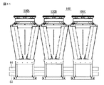
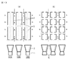
図11は本発明の実施の形態2による熱源ユニットを熱源ユニットの短手側の方向から見た図、図12は図11の熱源ユニットの連結状況を模式的に示す図であり、(a)は熱源ユニットの長手側から見た図、(b)は熱源ユニットの上面図である。図13は図11に示す熱源ユニットの中央部の空気熱交換器での吸込み圧損分布を先行例と比較して説明する図であり、(a)は実施の形態2の場合、(b)は先行例の場合である。なお、図13において、(a)、(b)の何れも上段側は熱源ユニットの空気熱交換器を上から見た模式図、下段側は連結された熱源ユニットを機械室の短手側から見た模式図である。
FIG. 11 is a view of the heat source unit according to
図において、熱源ユニット100は、実施の形態1と同様の複数(ここでは3ユニット)の熱源ユニット100A〜100Cが、短手方向に連結するように並置され、それぞれ主戻り管63及び主送給管64に接続されて成っている。各熱源ユニット100A〜100Cの戻り管33は全てそれよりも流路径が大型の主戻り管63に連結され、送給管34は全てそれよりも流路径が大型の主送給管64に連結されている。また、これら主戻り管63と主送給管64は大量の熱を使用する図示していない利用側の設備と連結されている。
このような設置形態の熱源ユニット100を用いて熱を利用側の設備に供給する場合、連結された熱源ユニットは、トータルで必要な熱量を供給できるように調整しながら運転制御される。また、例えば一時的に必要な熱量が大きく減少する場合は、その供給量に合わせて必要な台数だけ熱源ユニットを動かすことで熱量の調整が可能となる。In the figure, the
When heat is supplied to the equipment on the use side using the
以下、通常の運用である設備された全ての熱源ユニットを動かす場合を例に実施の形態2の動作について説明する。
連結された3つの熱源ユニット100A〜100Cの内、両端以外の熱源ユニット100Bでは、空気熱交換器2が熱交換のために吸い込む空気は、図13(a)の矢印で示すように、熱源ユニットの短手側にできた隣接する熱源ユニットの隙間から熱源ユニット長手方向に流れていき、空気熱交換器2の長辺部2a各部で、長方形の枠状に形成された熱源ユニット送風機室5の内部に吸い込まれる。
このような構成によると、図13(b)に示す先行例1の連結設置形態と、本発明について隣接する熱源ユニットで構成される空気の吸込みスペースを比較すると、先行例1では空気の吸込みスペース面を形成する五角形Eの底辺が隣接する辺と作る角度が鈍角であるのに対し、本発明では垂直にすることができるため、本発明の方が空気の吸込みスペースをより広く確保できるため、空気の吸込みで発生する圧損が減少し、より効率の高い運転が可能となる。Hereinafter, the operation of the second embodiment will be described by taking as an example the case of moving all installed heat source units in normal operation.
Of the three connected
According to such a configuration, when the connection installation form of the first example shown in FIG. 13B is compared with the air suction space formed by the adjacent heat source units in the present invention, the first example 1 has the air suction space. Whereas the angle that the base of the pentagon E forming the surface forms with the adjacent side is an obtuse angle, in the present invention it can be made vertical, so the present invention can secure a wider air suction space, Pressure loss caused by air suction is reduced, and more efficient operation is possible.
また、熱源ユニット群の連結方向の両端部以外のユニットの空気熱交換器、ここでは連結した3台中、中央部の熱源ユニット100Bの空気熱交換器2への吸込み圧損は図13に「大」、または「小」のような文字によって、相対的な違いを示すように、本発明の実施の形態2の場合、及び先行例1の場合共に、吸込み部に近い部分では「小」、吸込み部から遠い部分においては「大」のような分布となる。なお、L字状の太い実線で示したものは本発明で用いるL字状に形成された1基の空気熱交換器を示し、コ字状の太い実線で示したものは先行例1で示されたコ字状に形成された1基の空気熱交換器を示している。そして、それらの空気熱交換器を囲む細い破線は、同一の破線で囲われた中にある空気熱交換器で一つの系統の冷媒回路が形成されていることを仮想線として示している。また、熱源ユニット群の連結方向の両端部のユニットの熱交換器、ここでは連結した3台中、両端部の熱源ユニット100A、100Cについて、連結方向両端部に該当する空気熱交換器2への吸込み圧損は、その他の空気熱交換器2と比較して少なくなるので、相対的な違いを示すよう「無」と記載している。
Further, the suction pressure loss to the
図13から明らかなように、(a)に示す実施の形態2の熱源ユニットでは、中央に位置する熱源ユニット100Bを構成する4系統の冷媒回路の空気熱交換器は、その全てが互いに同一の吸込み圧損となっているのに対して、(b)に示す先行例1の熱源ユニットでは、中央に位置する熱源ユニットを構成する4系統の冷媒回路の内、外気の吸込み側に位置する図における上下両端の2系統の熱源ユニットの空気熱交換器の吸込み圧損は「小」である一方、図における上下方向の中央部の2系統の熱源ユニットの空気熱交換器の吸込み圧損は「大」となっており、冷媒系統でばらつきが生じている。
As is clear from FIG. 13, in the heat source unit of the second embodiment shown in FIG. 13A, all of the four-system refrigerant circuit air heat exchangers constituting the
本発明の実施の形態2では各冷媒回路の圧縮機回転数等の制御を揃えることで、各冷媒回路によらず出力を同等にすることができる。このため、運転制御を行う際のパラメータの検討は冷媒回路11の1系統分の検討を行うだけで安定した出力のコントロールが可能となる。また、圧縮機等の要素機器の運転効率を含め、熱源ユニット全体の運転効率を最適化する設計を行う際、先行例1では各冷媒回路系統に対応する空気熱交換器の圧損分布状況が異なるので、複数の冷媒回路系統の状況を複合的に考慮する必要があるが、本発明では複数の冷媒回路系統で空気熱交換器に働く圧損の状態が同等になるので、運転効率の設計は冷媒回路の1系統分の範囲内で済み、簡易に性能設計することが可能となる。更に、先行例1では複数の冷媒回路系統の出力の和が大きくなるような制御設計を行う必要があるのに対し、本発明では冷媒回路の1系統のみでの制御設計で済むので、より効率的な出力が得られる制御設計が可能となる。そして、空気熱交換器への吸込み圧損が従来よりも少なくなり、より効率的な熱源ユニットの運転が可能となる。
In
実施の形態3.
実施の形態2に示す各冷媒回路11をコントロールする制御盤群17は、通常は図15(a)に示す通り、各制御系統に対応した個別の制御盤が集められる形で構成されているが、例えば図15(b)に示す通り、各制御系統を制御する制御盤を共通化する形態をとると、実施の形態2に示した通り冷媒回路1系統の制御を共通化しても効率的な出力を得られるため、各冷媒回路11のコントロール機構を個別に割り当てた場合と比較して、出力効率を維持したままコストを低減することが可能となる。
また、実施の形態2に示す各冷媒回路11の制御方法の場合、熱源ユニット群の連結方向の両端部のユニットの空気熱交換器、ここでは連結した3台中、両端部の熱源ユニット100A、100Cの空気熱交換器2への吸込み圧損は連結の外側の面と内側の面で異なるため、両端部の熱源ユニットでは両端部以外の熱源ユニットと比較して、運転効率が低下することになる。連結ユニット数が多ければ連結した熱源ユニット全体の運転効率の低下の度合いは小さくすることができるが、連結数が少ない場合や、要求される運転効率の水準が高い場合には、図15(c)に示す通り熱源機長手方向の同一面に空気熱交換器が配置された冷媒回路同士のみでコントロール機構を共通化することによって、コントロール機構の簡略化をある程度実現しつつ実施の形態2よりも効率的な運転が可能となる。
The
In the case of the control method for each
実施の形態4.
図14は本発明の実施の形態4による熱源ユニットの連結状況を模式的に示す図であり、(a)は熱源ユニットの長手側から見た図、(b)はその上面図である。図において、熱源ユニット100は、実施の形態1と同様の熱源ユニット100A〜100Cが短手方向へ3基連結されており、その点は実施の形態2と同様である。実施の形態2と異なる点は、利用側に対する主送給管64と利用側からの主戻り管63が機械室1における短手方向に該機械室を貫通するように設置され、かつ主送給管64と主戻り管63の短手方向の各端部には、熱源ユニット100A〜100Cを連結するときに隣り合う主送給管64または主戻り管63を相互に連結するための接続部60が設けられていることである。これにより、この実施の形態4では図14(b)に示すように、主送給管64と主戻り管63が連結された各熱源ユニットを直線状に貫通するように設置されている。なお、各熱源ユニットの送給管34と戻り管33(図9参照)は、機械室1の内部でそれぞれ対応する主送給管64と主戻り管63に接続される。Embodiment 4 FIG.
14A and 14B are diagrams schematically showing the connection state of the heat source units according to the fourth embodiment of the present invention, where FIG. 14A is a view seen from the longitudinal side of the heat source units, and FIG. 14B is a top view thereof. In the figure, the
上記のように構成された実施の形態4では、各熱源ユニット100A〜100Cの機械室1に内蔵された図示していない水配管ヘッダ同士が当該機械室の内部で、対応する主送給管64または主戻り管63に連結されている。このような構成であれば従来は熱源ユニットが連続設置されている空間の外側に突出していた熱源を付加する伝熱流体の供給排出の配管を、熱源ユニットが連続設置されている空間内に納めることができるので設置スペースの削減が可能となる。また、本発明では熱源ユニットに内蔵された配管を接続部60で連結させるだけで良いので、必要な工数や、部品点数を削減することができるので、現地の取り付け作業の簡易化、更に取り付けに必要な配管等の更なるコスト低減が可能となる。
In the fourth embodiment configured as described above, water pipe headers (not shown) built in the
なお、本発明は、その発明の範囲内において、各実施の形態の一部または全部を自由に組合せたり、各実施の形態を適宜、変形、省略することが可能である。
例えば、上記実施の形態では、4基の空気熱交換器2A〜2Dを互いに独立した4系統の冷凍回路に接続した例で説明したが、必ずしもそれに限定されず、例えば4基の空気熱交換器2A〜2Dを互いに独立した2系統の冷凍回路に2基ずつ接続するなど、適宜変更しても良い。
また、空気熱交換器2のヘアピン部2cの位置とヘッダ部2dの位置を逆にすることもできる。その場合、ヘッダ部2dのメンテナンス性は悪くなるものの、ヘッダ部2dの位置が機械室1の長手方向中央部となるため、その中央部に設置された冷媒回路11の圧縮機などとの距離が近くなるので冷凍回路の配管長を短くできるという利点がある。It should be noted that within the scope of the present invention, a part or all of each embodiment can be freely combined, or each embodiment can be appropriately modified or omitted.
For example, in the above-described embodiment, the example in which the four
Moreover, the position of the
1 機械室、11 冷媒回路、17 制御盤群、2(2A〜2D) 空気熱交換器、2a 長辺部、2b 短辺部、2c ヘアピン部、2d ヘッダ部、3 熱交換装置、33 戻り管、34 送給管、40 ファン、5 送風機室、60 接続部、63 主戻り管、64 主送給管、100(100A、100B、100C) 熱源ユニット。
DESCRIPTION OF
Claims (8)
Applications Claiming Priority (3)
| Application Number | Priority Date | Filing Date | Title |
|---|---|---|---|
| JP2015086397 | 2015-04-21 | ||
| JP2015086397 | 2015-04-21 | ||
| PCT/JP2016/062527 WO2016171177A1 (en) | 2015-04-21 | 2016-04-20 | Heat source unit |
Related Child Applications (1)
| Application Number | Title | Priority Date | Filing Date |
|---|---|---|---|
| JP2018208601A Division JP2019015503A (en) | 2015-04-21 | 2018-11-06 | Heat source unit |
Publications (2)
| Publication Number | Publication Date |
|---|---|
| JPWO2016171177A1 JPWO2016171177A1 (en) | 2017-07-13 |
| JP6433582B2 true JP6433582B2 (en) | 2018-12-05 |
Family
ID=57143109
Family Applications (2)
| Application Number | Title | Priority Date | Filing Date |
|---|---|---|---|
| JP2017514166A Active JP6433582B2 (en) | 2015-04-21 | 2016-04-20 | Heat source unit |
| JP2018208601A Pending JP2019015503A (en) | 2015-04-21 | 2018-11-06 | Heat source unit |
Family Applications After (1)
| Application Number | Title | Priority Date | Filing Date |
|---|---|---|---|
| JP2018208601A Pending JP2019015503A (en) | 2015-04-21 | 2018-11-06 | Heat source unit |
Country Status (5)
| Country | Link |
|---|---|
| US (1) | US10436458B2 (en) |
| EP (1) | EP3287706B1 (en) |
| JP (2) | JP6433582B2 (en) |
| CN (1) | CN107532805A (en) |
| WO (1) | WO2016171177A1 (en) |
Families Citing this family (9)
| Publication number | Priority date | Publication date | Assignee | Title |
|---|---|---|---|---|
| JP6269717B2 (en) * | 2016-04-21 | 2018-01-31 | ダイキン工業株式会社 | Heat source unit |
| WO2017190769A1 (en) * | 2016-05-03 | 2017-11-09 | Carrier Corporation | Heat exchanger arrangement |
| WO2019012619A1 (en) * | 2017-07-12 | 2019-01-17 | 三菱電機株式会社 | Heat source unit |
| US11454420B2 (en) * | 2019-02-06 | 2022-09-27 | Johnson Controls Tyco IP Holdings LLP | Service plate for a heat exchanger assembly |
| EP4012291A4 (en) * | 2019-08-07 | 2022-08-10 | Mitsubishi Electric Corporation | Chilling unit |
| US20220252281A1 (en) * | 2019-08-07 | 2022-08-11 | Mitsubishi Electric Corporation | Chilling unit and chilling unit system |
| EP3936784A1 (en) * | 2020-07-07 | 2022-01-12 | Carrier Corporation | Coil cleaning easy access |
| IT202100030377A1 (en) * | 2021-12-01 | 2023-06-01 | Hiref S P A | AIR LIQUID COOLER |
| JP2024010814A (en) * | 2022-07-13 | 2024-01-25 | 三菱重工業株式会社 | Heat exchanger unit, positioning method, and method of assembling heat exchanger unit |
Family Cites Families (33)
| Publication number | Priority date | Publication date | Assignee | Title |
|---|---|---|---|---|
| JPS592809B2 (en) * | 1976-07-06 | 1984-01-20 | 三菱電機株式会社 | cooling device |
| JPS6021642Y2 (en) * | 1980-06-24 | 1985-06-27 | 太産工業株式会社 | Electromagnetic pump drive circuit |
| EP0095865A3 (en) | 1982-06-01 | 1984-02-08 | Celanese Corporation | Thermoformed shaped articles of thermotropic liquid crystal polymers and methods of production thereof |
| JPS6021642A (en) * | 1983-07-15 | 1985-02-04 | Nippon Telegr & Teleph Corp <Ntt> | System for processing mobile communication call |
| JPS6021642U (en) * | 1983-07-19 | 1985-02-14 | 三菱電機株式会社 | air conditioner |
| EP0190167B1 (en) | 1984-07-24 | 1991-03-13 | Multistack International Pty. Ltd. | Modular refrigeration system |
| JPS6229851A (en) * | 1985-07-30 | 1987-02-07 | Toshiba Corp | Air conditioner |
| JPH072859U (en) * | 1993-05-28 | 1995-01-17 | ヤンマーディーゼル株式会社 | Heat exchanger |
| JPH0914698A (en) * | 1995-06-23 | 1997-01-17 | Sharp Corp | Outdoor machine of air conditioner |
| JP3731095B2 (en) | 1996-10-22 | 2006-01-05 | ダイキン工業株式会社 | Control device for refrigeration equipment |
| US6969422B2 (en) * | 2000-09-20 | 2005-11-29 | Goodrich Corporation | Inorganic matrix composition and composites incorporating the matrix composition |
| JP2003240276A (en) * | 2002-02-13 | 2003-08-27 | Daikin Ind Ltd | Outdoor unit for air-conditioner |
| JP2004183906A (en) | 2002-11-29 | 2004-07-02 | Fujitsu General Ltd | Air conditioner |
| US7921904B2 (en) * | 2007-01-23 | 2011-04-12 | Modine Manufacturing Company | Heat exchanger and method |
| US9410709B2 (en) * | 2007-04-05 | 2016-08-09 | Johnson Controls Technology Company | Multichannel condenser coil with refrigerant storage receiver |
| US7942020B2 (en) * | 2007-07-27 | 2011-05-17 | Johnson Controls Technology Company | Multi-slab multichannel heat exchanger |
| JP4937240B2 (en) | 2008-12-10 | 2012-05-23 | 三菱電機株式会社 | Refrigeration cycle equipment |
| KR20100121961A (en) * | 2009-05-11 | 2010-11-19 | 엘지전자 주식회사 | Air conditioner |
| CN105650947A (en) | 2009-07-28 | 2016-06-08 | 东芝开利株式会社 | Heat source unit |
| JP5493736B2 (en) * | 2009-11-10 | 2014-05-14 | 三菱電機株式会社 | Air conditioner outdoor unit |
| JP2011158109A (en) | 2010-01-29 | 2011-08-18 | Sanyo Electric Co Ltd | Outdoor unit of freezing machine |
| CN102753895B (en) * | 2010-02-15 | 2015-07-15 | 东芝开利株式会社 | Chilling unit |
| JP5500725B2 (en) * | 2010-06-30 | 2014-05-21 | 株式会社日本イトミック | Heat pump type heat source machine |
| JP5517801B2 (en) | 2010-07-13 | 2014-06-11 | 三菱電機株式会社 | Heat exchanger and heat pump system equipped with this heat exchanger |
| JP2013160445A (en) * | 2012-02-06 | 2013-08-19 | Hitachi Appliances Inc | Heat exchanging unit and heat exchanger |
| WO2013151005A1 (en) * | 2012-04-04 | 2013-10-10 | 東芝キヤリア株式会社 | Composite dual refrigeration cycle device |
| JP5951475B2 (en) * | 2012-12-27 | 2016-07-13 | ジョンソンコントロールズ ヒタチ エア コンディショニング テクノロジー(ホンコン)リミテッド | Air conditioner and outdoor heat exchanger used therefor |
| JP2015055410A (en) * | 2013-09-11 | 2015-03-23 | ダイキン工業株式会社 | Method of manufacturing heat exchanger, heat exchanger, and air conditioner |
| US10837720B2 (en) * | 2013-11-06 | 2020-11-17 | Trane International Inc. | Heat exchanger with aluminum tubes rolled into an aluminum tube support |
| CN103759553B (en) | 2014-02-17 | 2016-05-11 | 丹佛斯微通道换热器(嘉兴)有限公司 | Heat-exchanger rig and heat source unit |
| CN103925742B (en) * | 2014-04-18 | 2016-06-29 | 丹佛斯微通道换热器(嘉兴)有限公司 | Heat exchanger and manufacture method, heat exchange module, heat-exchanger rig and heat source unit |
| KR20160131577A (en) * | 2015-05-08 | 2016-11-16 | 엘지전자 주식회사 | Heat exchanger for air conditioner |
| US20170130974A1 (en) * | 2015-11-09 | 2017-05-11 | Carrier Corporation | Residential outdoor heat exchanger unit |
-
2016
- 2016-04-20 EP EP16783198.1A patent/EP3287706B1/en active Active
- 2016-04-20 JP JP2017514166A patent/JP6433582B2/en active Active
- 2016-04-20 WO PCT/JP2016/062527 patent/WO2016171177A1/en active Application Filing
- 2016-04-20 US US15/565,246 patent/US10436458B2/en active Active
- 2016-04-20 CN CN201680023038.8A patent/CN107532805A/en active Pending
-
2018
- 2018-11-06 JP JP2018208601A patent/JP2019015503A/en active Pending
Also Published As
| Publication number | Publication date |
|---|---|
| WO2016171177A1 (en) | 2016-10-27 |
| EP3287706A4 (en) | 2019-01-16 |
| US10436458B2 (en) | 2019-10-08 |
| JPWO2016171177A1 (en) | 2017-07-13 |
| CN107532805A (en) | 2018-01-02 |
| EP3287706A1 (en) | 2018-02-28 |
| US20180080667A1 (en) | 2018-03-22 |
| JP2019015503A (en) | 2019-01-31 |
| EP3287706B1 (en) | 2023-03-15 |
Similar Documents
| Publication | Publication Date | Title |
|---|---|---|
| JP6433582B2 (en) | Heat source unit | |
| JP5581671B2 (en) | Air conditioner outdoor unit | |
| US11274838B2 (en) | Air-conditioner outdoor heat exchanger and air-conditioner including the same | |
| US9234673B2 (en) | Heat exchanger with subcooling circuit | |
| JP5817775B2 (en) | Chiller device | |
| US20200166278A1 (en) | Heat exchanger | |
| KR20030067515A (en) | Air conditioning device | |
| JP6553981B2 (en) | Heat exchange equipment for heat pump equipment | |
| JP2012013302A (en) | Heat pump type heat source machine | |
| WO2019008664A1 (en) | Refrigeration cycle device | |
| JP5592233B2 (en) | Air conditioner | |
| JPWO2020218059A1 (en) | Local cooler and local cooling method | |
| EP3382287B1 (en) | Fan coil unit | |
| JP6104378B2 (en) | Air conditioner | |
| JP6624851B2 (en) | Air conditioner and its indoor unit | |
| KR100784845B1 (en) | Air conditioner for cooling and heating having multiple 4-way valve | |
| JP6601886B1 (en) | Air source heat pump unit | |
| WO2024069861A1 (en) | Heat exchange device and cooling device | |
| WO2024069869A1 (en) | Heat exchange device and refrigeration device | |
| CN114440328A (en) | Heat exchanger and refrigeration cycle device provided with same | |
| KR102076679B1 (en) | A heat exchanger and a natural coolant circulation air conditioner | |
| JP5817058B2 (en) | Heat exchange unit and temperature control device | |
| US20230221013A1 (en) | Multiple Fan HVAC System with Optimized Fan Location | |
| US20230221012A1 (en) | Multiple Fan HVAC System with Optimized Fan Location | |
| KR20080012515A (en) | Fin of heat exchanger |
Legal Events
| Date | Code | Title | Description |
|---|---|---|---|
| A621 | Written request for application examination |
Free format text: JAPANESE INTERMEDIATE CODE: A621 Effective date: 20170208 |
|
| A131 | Notification of reasons for refusal |
Free format text: JAPANESE INTERMEDIATE CODE: A131 Effective date: 20180327 |
|
| A521 | Request for written amendment filed |
Free format text: JAPANESE INTERMEDIATE CODE: A523 Effective date: 20180515 |
|
| TRDD | Decision of grant or rejection written | ||
| A01 | Written decision to grant a patent or to grant a registration (utility model) |
Free format text: JAPANESE INTERMEDIATE CODE: A01 Effective date: 20181009 |
|
| A61 | First payment of annual fees (during grant procedure) |
Free format text: JAPANESE INTERMEDIATE CODE: A61 Effective date: 20181106 |
|
| R151 | Written notification of patent or utility model registration |
Ref document number: 6433582 Country of ref document: JP Free format text: JAPANESE INTERMEDIATE CODE: R151 |
|
| R250 | Receipt of annual fees |
Free format text: JAPANESE INTERMEDIATE CODE: R250 |
|
| R250 | Receipt of annual fees |
Free format text: JAPANESE INTERMEDIATE CODE: R250 |
|
| R250 | Receipt of annual fees |
Free format text: JAPANESE INTERMEDIATE CODE: R250 |