JP5817058B2 - Heat exchange unit and temperature control device - Google Patents

Heat exchange unit and temperature control device Download PDF

Info

Publication number
JP5817058B2
JP5817058B2 JP2011185650A JP2011185650A JP5817058B2 JP 5817058 B2 JP5817058 B2 JP 5817058B2 JP 2011185650 A JP2011185650 A JP 2011185650A JP 2011185650 A JP2011185650 A JP 2011185650A JP 5817058 B2 JP5817058 B2 JP 5817058B2
Authority
JP
Japan
Prior art keywords
heat exchange
tube
heat
fins
exchange unit
Prior art date
Legal status (The legal status is an assumption and is not a legal conclusion. Google has not performed a legal analysis and makes no representation as to the accuracy of the status listed.)
Active
Application number
JP2011185650A
Other languages
Japanese (ja)
Other versions
JP2013047578A (en
JP2013047578A5 (en
Inventor
田中 孝典
孝典 田中
Current Assignee (The listed assignees may be inaccurate. Google has not performed a legal analysis and makes no representation or warranty as to the accuracy of the list.)
Orion Machinery Co Ltd
Original Assignee
Orion Machinery Co Ltd
Priority date (The priority date is an assumption and is not a legal conclusion. Google has not performed a legal analysis and makes no representation as to the accuracy of the date listed.)
Filing date
Publication date
Application filed by Orion Machinery Co Ltd filed Critical Orion Machinery Co Ltd
Priority to JP2011185650A priority Critical patent/JP5817058B2/en
Publication of JP2013047578A publication Critical patent/JP2013047578A/en
Publication of JP2013047578A5 publication Critical patent/JP2013047578A5/ja
Application granted granted Critical
Publication of JP5817058B2 publication Critical patent/JP5817058B2/en
Active legal-status Critical Current
Anticipated expiration legal-status Critical

Links

Images

Description

本発明は、二系統の熱媒体循環回路における一方の熱媒体循環回路の熱媒体により冷却を行う第一熱交換部と他方の熱媒体循環回路の熱媒体により加熱を行う第二熱交換部を含む熱交換ユニット及び温度調整装置に関する。   The present invention includes a first heat exchange section that cools with a heat medium of one heat medium circulation circuit and a second heat exchange section that heats with a heat medium of the other heat medium circulation circuit in two heat medium circulation circuits. The present invention relates to a heat exchange unit and a temperature control device.

従来、熱媒体が流通循環する二系統の熱媒体循環回路における一方の熱媒体循環回路の熱媒体により冷却を行う第一熱交換部と他方の熱媒体循環回路の熱媒体により加熱を行う第二熱交換部とを含む熱交換処理部を備える温度調整装置としては、特許文献1で開示される温度調整装置が知られている。   Conventionally, in a two-system heat medium circulation circuit in which a heat medium flows and circulates, a first heat exchange unit that performs cooling with the heat medium of one heat medium circuit and a second that performs heating with the heat medium of the other heat medium circuit As a temperature adjustment device including a heat exchange processing unit including a heat exchange unit, a temperature adjustment device disclosed in Patent Document 1 is known.

同温度調整装置は、圧縮機からの高温熱媒体の一部を供給する加熱器と、高温熱媒体の残余部を冷却した冷却媒体を供給する冷却器とから成る熱交換器と、高温熱媒体を加熱器側と冷却器側とに分配する三方弁と、加熱器で冷却・凝縮された熱媒体を加熱するヒートポンプ手段と、冷却器及びヒートポンプ手段で加熱された熱媒体を圧縮機に供給する供給手段と、圧縮機の回転数を制御するインバータとを具備し、加熱器側と冷却器側とに分配する高温熱媒体の分配比率を連続的に変更して、熱交換器を通過する流体を所定温度に調整するように三方弁を制御する第1制御部と、適切な分配比率となるように、圧縮機の回転数を変更する第2制御部とから成る温度調整装置において、空間ユニット内に前後して配した加熱器と冷却器に対してファンにより送風することにより外気との熱交換を行うようにしたものである。   The temperature adjusting device includes a heat exchanger that includes a heater that supplies a part of the high-temperature heat medium from the compressor, a cooler that supplies a cooling medium that has cooled the remainder of the high-temperature heat medium, and a high-temperature heat medium. A three-way valve that distributes the heat to the heater side and the cooler side, a heat pump means for heating the heat medium cooled and condensed by the heater, and a heat medium heated by the cooler and the heat pump means to the compressor A fluid that includes a supply means and an inverter that controls the number of revolutions of the compressor, continuously changes a distribution ratio of the high-temperature heat medium distributed to the heater side and the cooler side, and passes through the heat exchanger In the temperature adjustment apparatus comprising a first control unit that controls the three-way valve so as to adjust the temperature to a predetermined temperature, and a second control unit that changes the rotation speed of the compressor so as to obtain an appropriate distribution ratio, For heaters and coolers placed back and forth inside It is obtained to perform the heat exchange with the outside air by blowing with § emissions.

特開2008−309465号公報JP 2008-309465 A

しかし、上述した特許文献1に開示される温度調整装置は、次のような解決すべき課題が存在した。   However, the temperature adjusting device disclosed in Patent Document 1 described above has the following problems to be solved.

第一に、送風により外気との熱交換を行う冷却器(蒸発器)と加熱器(凝縮器)は、それぞれ別個に構成され、かつ送風方向の前後に配設されるため、独立した二つの熱交換器をそれぞれ別々に組付ける必要がある。したがって、部品点数の増加による部品コスト及び配設スペースの拡大(大型化)を招くとともに、組付工数も増加し、生産効率の低下及び生産コストの上昇を招く。   First, the cooler (evaporator) and the heater (condenser) that exchange heat with the outside air by blowing are separately configured and disposed before and after the blowing direction, so two independent Each heat exchanger needs to be assembled separately. Therefore, the increase in the number of parts causes an increase in the part cost and the installation space (enlargement), and the number of assembling steps also increases, resulting in a decrease in production efficiency and an increase in production cost.

第二に、冷却器及び加熱器の一方の使用を100〔%〕又はそれに近い状態で運転する場合、他方はほとんど使用されない状態になるとともに、使用されない冷却器又は加熱器は無用な存在となる。したがって、各部品を有効に使用することにより、全体の加熱冷却能力及び加熱冷却効率を向上させる観点からは必ずしも十分であるとは言えず、更なる改善の余地があった。   Secondly, if one of the cooler and the heater is operated at or near 100%, the other is hardly used, and the unused cooler or heater is useless. . Therefore, it is not necessarily sufficient from the viewpoint of improving the overall heating / cooling capacity and heating / cooling efficiency by effectively using each component, and there is room for further improvement.

本発明は、このような背景技術に存在する課題を解決した熱交換ユニット及び温度調整装置の提供を目的とするものである。   The object of the present invention is to provide a heat exchange unit and a temperature control device that solve the problems in the background art.

本発明に係る熱交換ユニット1は、上述した課題を解決するため、熱媒体Kが流通循環する二系統の熱媒体循環回路Cc,Chにおける一方の熱媒体循環回路Ccの熱媒体Kにより冷却を行う第一熱交換部2cと他方の熱媒体循環回路Chの熱媒体Kにより加熱を行う第二熱交換部2hを含むフィンアンドチューブ方式により構成した熱交換ユニットであって、第一熱交換部2c及び第二熱交換部2hに共通に用いる複数の配列したフィン3…と、第一熱交換部2cに対応し、かつ各フィン3…に貫通する複数の第一チューブ構成部4c…と、第二熱交換部2hに対応し、かつ各フィン3…に貫通する複数の第二チューブ構成部4h…とを備え、各フィン3…に貫通する第一チューブ構成部4c…と第二チューブ構成部4h…を、横方向に交互に配置するとともに、縦方向に交互に配置することにより、一体に構成してなることを特徴とする。   In order to solve the above-described problem, the heat exchange unit 1 according to the present invention is cooled by the heat medium K of one heat medium circuit Cc in the two heat medium circuits Cc and Ch in which the heat medium K circulates and circulates. A heat exchange unit configured by a fin-and-tube system including a first heat exchange part 2c to be performed and a second heat exchange part 2h to be heated by the heat medium K of the other heat medium circulation circuit Ch, the first heat exchange part 2c and a plurality of arranged fins 3 used in common for the second heat exchange part 2h, and a plurality of first tube constituent parts 4c corresponding to the first heat exchange part 2c and penetrating through the fins 3 ... A plurality of second tube constituent parts 4h corresponding to the second heat exchange part 2h and penetrating through the fins 3 ..., and first tube constituent parts 4c penetrating through the fins 3 ... and second tube constituents. 4h ... in the horizontal direction While it disposed, by alternately arranging the vertical direction, and characterized by being configured integrally.

この場合、発明の好適な態様により、各第一チューブ構成部4c…の端部同士及び各第二チューブ構成部4h…の端部同士は、U形接続チューブ4j…により接続できる。この際、各第一チューブ構成部4c…と各第二チューブ構成部4h…は、第一チューブ構成部4c…単位及び第二チューブ構成部4h…単位で交互に配置することができる。   In this case, according to a preferred aspect of the invention, the end portions of the first tube constituting portions 4c and the end portions of the second tube constituting portions 4h can be connected by the U-shaped connecting tubes 4j. In this case, the first tube components 4c and the second tube components 4h can be alternately arranged in units of the first tube components 4c and the second tube components 4h.

一方、本発明に係る温度調整装置Mは、上述した課題を解決するため、熱媒体Kが流通循環する二系統の熱媒体循環回路Cc,Chにおける一方の熱媒体循環回路Ccの熱媒体Kにより冷却を行う第一熱交換部2cと他方の熱媒体循環回路Chの熱媒体Kにより加熱を行う第二熱交換部2hを含むフィンアンドチューブ方式により構成した熱交換ユニット1を、熱交換用流体Wが流通する共通の熱交換通路R内に配設した熱交換処理部Sを備える温度調整装置であって、第一熱交換部2c及び第二熱交換部2hに共通に用いる複数の配列したフィン3…と、第一熱交換部2cに対応し、かつ各フィン3…に貫通する複数の第一チューブ構成部4c…と、第二熱交換部2hに対応し、かつ各フィン3…に貫通する複数の第二チューブ構成部4h…とを備え、各フィン3…に貫通する第一チューブ構成部4c…と第二チューブ構成部4h…を、横方向に交互に配置するとともに、縦方向に交互に配置することにより、一体に構成してなる熱交換ユニット1を、熱交換通路R内に配設した熱交換処理部Sを備えることを特徴とする。   On the other hand, the temperature adjusting device M according to the present invention uses the heat medium K of one heat medium circuit Cc in the two heat medium circuits Cc and Ch in which the heat medium K circulates in order to solve the above-described problem. A heat exchange unit 1 configured by a fin-and-tube system including a first heat exchange part 2c for cooling and a second heat exchange part 2h for heating by the heat medium K of the other heat medium circuit Ch is used as a heat exchange fluid. A temperature adjustment device including a heat exchange processing unit S disposed in a common heat exchange passage R through which W circulates, and a plurality of arrangements commonly used for the first heat exchange unit 2c and the second heat exchange unit 2h Corresponding to the fins 3 ..., the first heat exchanging parts 2c and the plurality of first tube constituting parts 4c penetrating through the fins 3 ..., the second heat exchanging parts 2h, and the fins 3 ... A plurality of second tube components 4h that penetrate therethrough The first tube components 4c and the second tube components 4h penetrating through the fins 3 are alternately arranged in the horizontal direction and alternately arranged in the vertical direction. The heat exchanging unit 1 is provided with a heat exchanging section S disposed in the heat exchanging passage R.

この場合、発明の好適な態様により、二系統の熱媒体循環回路Cc,Chは、圧縮機5を共通にした第一冷凍サイクルCccと第二冷凍サイクルChcにより構成することができる。また、熱交換用流体Wには、送風ファン6により送られる空気Aを適用することができる。   In this case, according to a preferred aspect of the invention, the two heat medium circulation circuits Cc and Ch can be configured by the first refrigeration cycle Ccc and the second refrigeration cycle Chc having the compressor 5 in common. Further, the air A sent by the blower fan 6 can be applied to the heat exchange fluid W.

このような構成を有する本発明に係る熱交換ユニット1及び温度調整装置Mによれば、次のような顕著な効果を奏する。   According to the heat exchange unit 1 and the temperature adjustment device M according to the present invention having such a configuration, the following remarkable effects are achieved.

(1) 熱交換ユニット1は、第一熱交換部2c及び第二熱交換部2hに共通に用いる複数の配列したフィン3…と、第一熱交換部2cに対応し、かつ各フィン3…に貫通する複数の第一チューブ構成部4c…と、第二熱交換部2hに対応し、かつ各フィン3…に貫通する複数の第二チューブ構成部4h…とを備え、各フィン3…に貫通する第一チューブ構成部4c…と第二チューブ構成部4h…を、横方向に交互に配置するとともに、縦方向に交互に配置することにより、一体に構成してなるため、第一熱交換部2cと第二熱交換部2hとを含む単一部品として構成できる。これにより、部品点数の削減,部品コストの低減及び配設スペースの省スペース化による小型化を図れるとともに、加えて、組付工数の低減による生産効率の向上及び生産コストの低減に寄与できる。   (1) The heat exchange unit 1 corresponds to the plurality of arranged fins 3 used in common for the first heat exchange part 2c and the second heat exchange part 2h, and the first heat exchange part 2c, and each fin 3. Are provided with a plurality of first tube constituting portions 4c penetrating through the fins, and a plurality of second tube constituting portions 4h penetrating the fins 3 corresponding to the second heat exchanging portions 2h. Since the first tube component 4c and the second tube component 4h penetrating through are alternately arranged in the horizontal direction and alternately arranged in the vertical direction, they are integrally formed, so that the first heat exchange It can be configured as a single part including the part 2c and the second heat exchange part 2h. As a result, it is possible to reduce the number of parts, reduce the part cost, and reduce the size of the installation space. In addition, it is possible to contribute to the improvement of production efficiency and the reduction of the production cost by reducing the number of assembly steps.

(2) 第一熱交換部2c又は第二熱交換部2hの一方の使用を100〔%〕又はそれに近い状態で運転し、他方をほとんど使用しない場合であっても、第一熱交換部2c及び第二熱交換部2hの双方に共通に用いる複数の配列したフィン3…の全体を常時使用できるため、部品の有効利用に寄与できる。これにより、全体の加熱冷却能力及び加熱冷却効率を向上させることができるとともに、一方において、全体の加熱冷却能力を同等にする場合には、フィン3…のサイズダウンを図れるため、熱交換ユニット1の更なる小型化に寄与できる。   (2) Even if one of the first heat exchange part 2c and the second heat exchange part 2h is used in a state of 100 [%] or close to it and the other is hardly used, the first heat exchange part 2c And the entire plurality of arranged fins 3... Used in common for both the second heat exchanging part 2h can be used at all times, which can contribute to the effective use of parts. As a result, the overall heating / cooling capacity and heating / cooling efficiency can be improved. On the other hand, when the overall heating / cooling capacity is made equal, the size of the fins 3... Can be reduced. This can contribute to further downsizing of the product.

(3) 例えば、第一熱交換部2cを放熱器(又は冷却器)として使用し、第二熱交換部2hを吸熱器(又は加熱器)として使用するなど、第一熱交換部2cと第二熱交換部2hの使用態様によっては、フィン3…自体の熱伝導を直接利用した第一熱交換部2cと第二熱交換部2h間の熱交換により更なる冷却効率及び加熱効率の向上に寄与できる。   (3) For example, the first heat exchanging part 2c and the second heat exchanging part 2c are used as a heat sink (or a heater) and the second heat exchanging part 2h is used as a heat absorber (or a heater). Depending on the usage mode of the two heat exchanging parts 2h, the heat exchange between the first heat exchanging part 2c and the second heat exchanging part 2h directly utilizing the heat conduction of the fins 3 itself may further improve cooling efficiency and heating efficiency. Can contribute.

(4) 寒冷地で使用し、第二熱交換部2cに凍結の可能性がある環境下であってもフィン3…を介した熱伝導により凍結防止を図ることができる。   (4) It can be used in a cold region, and even in an environment where there is a possibility of freezing in the second heat exchange part 2c, it is possible to prevent freezing by heat conduction through the fins 3.

(5) 第一熱交換部2c及び第二熱交換部2hを含む熱交換ユニット1を一体に構成し、この熱交換ユニット1を熱交換通路R内に配設して熱交換処理部Sを構成するため、熱交換ユニット1における上述した各種作用効果を享受できる最適な温度調整装置Mを得ることができる。   (5) The heat exchanging unit 1 including the first heat exchanging part 2c and the second heat exchanging part 2h is integrally configured, and the heat exchanging unit 1 is disposed in the heat exchanging passage R so that the heat exchanging unit S is provided. Since it comprises, the optimal temperature control apparatus M which can enjoy the various effect mentioned above in the heat exchange unit 1 can be obtained.

(6) 好適な態様により、各第一チューブ構成部4c…の端部同士及び各第二チューブ構成部4h…の端部同士を、U形接続チューブ4j…により接続するようにすれば、第一チューブ構成部4c…と第二チューブ構成部4h…が横方向及び縦方向に交互に配置する構造であっても、フィンアンドチューブ方式による汎用的な熱交換器と同様に容易に製造することができる。   (6) If the end portions of the first tube constituent portions 4c and the end portions of the second tube constituent portions 4h are connected to each other by the U-shaped connecting tubes 4j according to a preferred embodiment, Even if one tube component 4c and second tube component 4h are arranged alternately in the horizontal and vertical directions, they can be easily manufactured in the same manner as a general heat exchanger using the fin-and-tube method. Can do.

(7) 好適な態様により、二系統の熱媒体循環回路Cc,Chを、圧縮機5を共通にした第一冷凍サイクルCccと第二冷凍サイクルChcにより構成するとともに、熱交換用流体Wに、送風ファン6により送られる空気Aを適用すれば、空気Aの温度を調整するための最良な温度調整装置Mを得ることができる。   (7) According to a preferred embodiment, the two heat medium circulation circuits Cc and Ch are constituted by the first refrigeration cycle Ccc and the second refrigeration cycle Chc that share the compressor 5, and the heat exchange fluid W If the air A sent by the blower fan 6 is applied, the best temperature adjusting device M for adjusting the temperature of the air A can be obtained.

本発明の好適実施形態に係る熱交換ユニットを備える温度調整装置の模式的構成図、The typical block diagram of a temperature control apparatus provided with the heat exchange unit which concerns on suitable embodiment of this invention, 同温度調整装置に備える熱交換ユニットの接続例を含む全体系統図、Overall system diagram including connection example of heat exchange unit provided in the temperature control device, 同温度調整装置の全体回路図、Overall circuit diagram of the temperature control device, 同温度調整装置に備える熱交換ユニットの一部を示す正面図、A front view showing a part of a heat exchange unit provided in the temperature control device, 同温度調整装置に備える熱交換ユニットの作用説明図、Operation explanatory diagram of the heat exchange unit provided in the temperature control device, 同熱交換ユニットの第一チューブ構成部と第二チューブ構成部の配置に係わる参考例を示す側面図、Side view showing a reference example related to the arrangement of the first tube component and the second tube component of the heat exchange unit, 同熱交換ユニットの第一チューブ構成部と第二チューブ構成部の配置に係わる他の参考例を示す側面図、A side view showing another reference example related to the arrangement of the first tube component and the second tube component of the heat exchange unit, 本発明の変更実施形態に係る温度調整装置の模式的構成図、The typical block diagram of the temperature control apparatus which concerns on the modified embodiment of this invention,

次に、本発明に係る好適実施形態を挙げ、図面に基づき詳細に説明する。   Next, preferred embodiments according to the present invention will be given and described in detail with reference to the drawings.

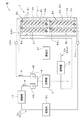
まず、本実施形態に係る熱交換ユニット1を備える温度調整装置Mの全体構造について、図1を参照して説明する。   First, the whole structure of the temperature control apparatus M provided with the heat exchange unit 1 which concerns on this embodiment is demonstrated with reference to FIG.

例示の温度調整装置Mは、空冷式の精密温度調整装置であり、全体を覆うハウジング11を備える。ハウジング11の内部は、上半部を空気制御処理室11uとして構成し、下半部を放熱処理室11dとして構成する。ハウジング11の正面(図1の右側面)には、上側に設けた空気吸込口11ui及び下側に設けた空気吸込口11diを有するとともに、ハウジング11の上面には、空気吹出口11ueを有し、更に、ハウジング11の背面下側には、放熱処理室11dが臨む空気吹出口11deを有する。なお、12…はハウジング11の底面に設けた複数のキャスタである。   The exemplary temperature adjusting device M is an air-cooled precision temperature adjusting device, and includes a housing 11 that covers the entire device. In the housing 11, the upper half is configured as an air control processing chamber 11u, and the lower half is configured as a heat dissipation processing chamber 11d. The front surface of the housing 11 (the right side surface in FIG. 1) has an air inlet port 11ui provided on the upper side and an air inlet port 11di provided on the lower side, and an air outlet port 11ue on the upper surface of the housing 11. Furthermore, an air outlet 11de facing the heat radiation processing chamber 11d is provided on the lower back side of the housing 11. Reference numerals 12... Are a plurality of casters provided on the bottom surface of the housing 11.

空気制御処理室11uには、送風ファン(例示はシロッコファン)13を配設し、この送風ファン13の吸入口13iは前通気ダクト14を介して空気吸込口11uiに連通接続するとともに、送風ファン13の吐出口13eは後通気ダクト15を介して外部に臨ませる。この後通気ダクト15は上述した空気吹出口11ueを兼用する。前通気ダクト14の内部には、正面側から吸込フィルタ(エアフィルタ)16,蒸発器(冷却器)17,凝縮器(加熱器)18を順次配設する。なお、13mは送風ファン13のファンモータを示す。また、空気制御処理室11uの内部にはケーシングに収容されたコントローラ19を備えるとともに、外部に配することにより空気吹出口11ueから吹き出す熱交換用流体W、即ち、空気Aの温度を検出する温度センサ20を備える。この温度センサ20はコントローラ19に接続する。コントローラ19は、各種制御処理等を行うコンピューティング機能を有し、少なくとも温度センサ20により空気吹出口11ueから吹き出す空気Aの温度を検出し、目標温度となるように、後述する圧縮機5を含む第一冷凍サイクルCcc及び第二冷凍サイクルChcを制御(フィードバック制御)するとともに、後述する第一調整弁43及び第二調整弁46を制御する機能を備える。   A blower fan (illustrated sirocco fan) 13 is disposed in the air control processing chamber 11u, and a suction port 13i of the blower fan 13 is connected to the air suction port 11ui through the front ventilation duct 14 and is connected to the blower fan. The 13 outlets 13 e are exposed to the outside through the rear ventilation duct 15. Thereafter, the air duct 15 also serves as the air outlet 11ue described above. Inside the front ventilation duct 14, a suction filter (air filter) 16, an evaporator (cooler) 17, and a condenser (heater) 18 are sequentially arranged from the front side. Reference numeral 13m denotes a fan motor of the blower fan 13. In addition, the air control processing chamber 11u includes a controller 19 housed in a casing, and a temperature for detecting the temperature of the heat exchange fluid W, that is, the air A, which is blown out from the air outlet 11ue by being arranged outside. A sensor 20 is provided. This temperature sensor 20 is connected to the controller 19. The controller 19 has a computing function for performing various control processes and the like, and includes a compressor 5 which will be described later so that the temperature of the air A blown from the air outlet 11ue is detected by at least the temperature sensor 20 and becomes the target temperature. While controlling (feedback control) the 1st freezing cycle Ccc and the 2nd freezing cycle Chc, the function which controls the 1st regulating valve 43 and the 2nd regulating valve 46 mentioned later is provided.

放熱処理室11dには、前端口21iを空気吸込口11diに連通接続し、かつ後端口21eを放熱処理室11dの内部に臨ませた通気ダクト21を配設する。この通気ダクト21の内部は空気A(熱交換用流体W)が流通する熱交換通路Rとなる。そして、この通気ダクト21の内部における正面側には吸込フィルタ(エアフィルタ)22を配設するとともに、この吸込フィルタ22の後方には、本実施形態に係る熱交換ユニット1を配設する。したがって、通気ダクト21の内部が熱交換処理部Sとして構成される。また、熱交換ユニット1の後方に位置する通気ダクト21の後端口21eには送風ファン6を配設する。なお、6mは送風ファン6のファンモータ、5は放熱処理室11dの内部に配設した圧縮機をそれぞれ示す。   In the heat radiation processing chamber 11d, there is disposed a ventilation duct 21 with the front end port 21i connected to the air suction port 11di and the rear end port 21e facing the inside of the heat radiation processing chamber 11d. The inside of the ventilation duct 21 becomes a heat exchange passage R through which air A (heat exchange fluid W) flows. A suction filter (air filter) 22 is disposed on the front side inside the ventilation duct 21, and the heat exchange unit 1 according to the present embodiment is disposed behind the suction filter 22. Therefore, the inside of the ventilation duct 21 is configured as the heat exchange processing unit S. A blower fan 6 is disposed at the rear end 21e of the ventilation duct 21 located behind the heat exchange unit 1. In addition, 6m shows the fan motor of the ventilation fan 6, 5 shows the compressor arrange | positioned in the inside of the thermal radiation processing chamber 11d, respectively.

次に、本実施形態に係る熱交換ユニット1の構成及び製造方法について、図1,図2及び図4を参照して説明する。   Next, the configuration and manufacturing method of the heat exchange unit 1 according to the present embodiment will be described with reference to FIGS. 1, 2, and 4.

本実施形態に係る熱交換ユニット1は、図1に示すように、第一熱交換部2c及び第二熱交換部2hを一体に構成したものであり、基本的には、第一熱交換部2c及び第二熱交換部2hに共通に用いる複数の配列したフィン3…と、第一熱交換部2cに対応し、かつ各フィン3…に貫通する複数の第一チューブ構成部4c…と、第二熱交換部2hに対応し、かつ各フィン3…に貫通する複数の第二チューブ構成部4h…とを有するとともに、少なくとも各フィン3…に接触する熱交換用流体W、即ち、送風ファン6により送風される空気(外気)Aの流通方向Fwにおける各フィン3…の上流側エリアZuと下流側エリアZdに、第一チューブ構成部4c…と第二チューブ構成部4h…とを混在させて配置し、フィンアンドチューブ方式により一体に構成する。この場合、第一熱交換部2cは、後述する第二冷凍サイクルChcにおける蒸発器(吸熱器)を構成するとともに、第二熱交換部2hは、後述する第一冷凍サイクルCccにおける凝縮器(放熱器)を構成する。   As shown in FIG. 1, the heat exchange unit 1 according to the present embodiment is configured by integrally forming a first heat exchange unit 2 c and a second heat exchange unit 2 h. Basically, the first heat exchange unit 2c and a plurality of arranged fins 3 used in common for the second heat exchange part 2h, and a plurality of first tube constituent parts 4c corresponding to the first heat exchange part 2c and penetrating through the fins 3 ... A heat exchange fluid W corresponding to the second heat exchanging part 2h and having a plurality of second tube constituent parts 4h penetrating through the fins 3 ... and at least in contact with the fins 3 ..., that is, a blower fan The first tube constituent portions 4c and the second tube constituent portions 4h are mixed in the upstream area Zu and the downstream area Zd of each fin 3 in the flow direction Fw of the air (outside air) A blown by the air 6. By fin and tube method It is integrally formed. In this case, the first heat exchanging part 2c constitutes an evaporator (heat absorber) in a second refrigeration cycle Chc described later, and the second heat exchange part 2h is a condenser (heat radiation) in a first refrigeration cycle Ccc described later. Device).

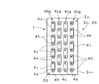
また、各フィン3…は、図4に示すように、所定の厚さを有し、かつ図1及び図2に示すように、全体が長方形となるように形成するとともに、面内には、後述する主チューブ部材4o…(第一チューブ構成部4c…,第二チューブ構成部4h…)が貫通する多数の円形貫通孔31…を形成する。なお、各フィン3…は、アルミニウム素材等の伝熱性の良好な素材により形成する。例示の円形貫通孔31…は、図2に示すように、一枚のフィン3において、横4列、縦16段に形成するとともに、各円形貫通孔31…の隣同士の間隔は縦横同一となるように形成した。そして、フィン3…における空気Aの送風方向(流通方向)Fwの前側半分を下流側エリアZdとし、後側半分を上流側エリアZuとした。なお、下流側エリアZdと上流側エリアZuは、必ずしも半分ずつであることを要せず、任意に設定できる。   Each fin 3 has a predetermined thickness as shown in FIG. 4 and is formed in a rectangular shape as shown in FIGS. 1 and 2. A large number of circular through-holes 31 are formed through which main tube members 4o (first tube component 4c, second tube component 4h,...) To be described later penetrate. Each fin 3 is formed of a material having good heat conductivity such as an aluminum material. As shown in FIG. 2, the illustrated circular through-holes 31 are formed in a single fin 3 in four rows and sixteen columns, and the intervals between the circular through-holes 31 are the same in the vertical and horizontal directions. It formed so that it might become. And the front half of the air A blowing direction (circulation direction) Fw in the fins 3 is defined as the downstream area Zd, and the rear half is defined as the upstream area Zu. The downstream area Zd and the upstream area Zu do not necessarily have to be half each, and can be arbitrarily set.

一方、第一チューブ構成部4c…及び第二チューブ構成部4h…には、伝熱性の良好な素材により、断面が円形となる直線状(I形)に形成した主チューブ部材4oを用いる。加えて、例示の場合には、さらに、図4に示すU形の接続チューブ部材4j…を用いる。接続チューブ部材4j…は、U形に湾曲し、かつ両端に主チューブ部材4oの端部にそれぞれ接続する接続口4js,4jtを有する点を除いて、形成素材及びチューブ径等は、主チューブ部材4oと同様に形成する。   On the other hand, for the first tube constituent portions 4c and the second tube constituent portions 4h, a main tube member 4o formed in a linear shape (I shape) having a circular cross section is used with a material having good heat conductivity. In addition, in the illustrated case, U-shaped connection tube members 4j shown in FIG. 4 are further used. The connecting tube member 4j is curved in a U shape, and the forming material, the tube diameter, and the like are the main tube member except that the connection ports 4js and 4jt are respectively connected to the ends of the main tube member 4o at both ends. It is formed in the same manner as 4o.

このような部材を有する熱交換ユニット1は、次のように製造することができる。まず、使用する所要枚数のフィン3…を用意し、図4に示すように、設定した等間隔で順次セッティングする。そして、用意した所要本数の主チューブ部材4o…を、各フィン3…における円形貫通孔31…に挿通させた後、溶接等により、各フィン3…に対して主チューブ部材4o…を固定する。また、接続チューブ部材4j…を用いて主チューブ部材4o…の端部同士を接続する。例示の場合、図2に示すように、横4列及び縦16段のため、横2列及び縦8段となる四つのブロックBa,Bb,Bc,Bdに分け、各ブロックBa…における各主チューブ部材4o…の一端側では、一方の列における任意の主チューブ部材4o…の端部と他方の列における一段下の主チューブ部材4o…の端部同士間を接続チューブ部材4j…により順次接続するとともに、各ブロックBa…における各主チューブ部材4o…の他端側では一方の列における任意の主チューブ部材4o…の端部と他方の列における一段上の主チューブ部材4o…の端部同士間を接続チューブ部材4j…により順次接続する。なお、各主チューブ部材4o…と各接続チューブ部材4j…の接続部分は、溶接等により固定及びシーリングを行う。このように、各主チューブ部材4o…の端部同士を、U形接続チューブ4j…により接続するようにすれば、後述する第一チューブ構成部4c…と第二チューブ構成部4h…が混在する構造であっても、フィンアンドチューブ方式による汎用的な熱交換器と同様に容易に製造できる利点がある。   The heat exchange unit 1 having such a member can be manufactured as follows. First, the required number of fins 3 to be used are prepared, and are sequentially set at set equal intervals as shown in FIG. Then, after the necessary number of prepared main tube members 4o are inserted through the circular through holes 31 in the fins 3, the main tube members 4o are fixed to the fins 3 by welding or the like. Further, the end portions of the main tube members 4o are connected to each other using the connection tube members 4j. In the case of the example, as shown in FIG. 2, since it has 4 rows and 16 columns, it is divided into four blocks Ba, Bb, Bc, and Bd that are 2 rows and 8 columns. On one end side of the tube members 4o, the end portions of the arbitrary main tube members 4o in one row and the end portions of the lower main tube members 4o in the other row are sequentially connected by the connection tube members 4j. In addition, on the other end side of each main tube member 4o ... in each block Ba ..., an end portion of an arbitrary main tube member 4o ... in one row and an end portion of the main tube member 4o ... in the other row The space is sequentially connected by connecting tube members 4j. The connecting portions of the main tube members 4o and the connection tube members 4j are fixed and sealed by welding or the like. In this way, if the end portions of the main tube members 4o are connected to each other by the U-shaped connection tubes 4j, a first tube constituent portion 4c and a second tube constituent portion 4h, which will be described later, are mixed. Even if it is a structure, there exists an advantage which can be manufactured easily similarly to the general purpose heat exchanger by a fin and tube system.

これにより、各ブロックBa…には連続した二本の熱交換チューブが構成され、一方の熱交換チューブは、複数の第一チューブ構成部4c…が接続チューブ部材4j…を介して順次接続される第一熱交換部2cの一部となる。また、他方の熱交換チューブは、複数の第二チューブ構成部4h…が接続チューブ部材4j…を介して順次接続される第二熱交換部2hの一部となる。なお、四つの各ブロックBa…は、同一構成となり、第一チューブ構成部4c…と第二チューブ構成部4h…は、側面から見た場合、図1に示すように、各第一チューブ構成部4c…単位及び各第二チューブ構成部4h…単位により横方向及び縦方向へ交互に配置されることになる。図1中、第一チューブ構成部4cを「C」で表示するとともに、第二チューブ構成部4hを「H」で表示している。   Thereby, two continuous heat exchange tubes are constituted in each block Ba ..., and one of the heat exchange tubes is sequentially connected with a plurality of first tube constituent parts 4c ... via connection tube members 4j .... It becomes a part of the first heat exchange part 2c. The other heat exchange tube is a part of the second heat exchange part 2h in which a plurality of second tube constituent parts 4h... Are sequentially connected via connection tube members 4j. Each of the four blocks Ba has the same configuration, and the first tube component 4c and the second tube component 4h when viewed from the side face, as shown in FIG. 4c... And the second tube components 4h... Are alternately arranged in the horizontal direction and the vertical direction depending on the unit. In FIG. 1, the first tube component 4 c is indicated by “C” and the second tube component 4 h is indicated by “H”.

そして、各ブロックBa…における一方の熱交換チューブにおける一方の端(下端)に位置する各第一チューブ構成部4c…は、ヘッダ41cに接続するとともに、他方の端(上端)に位置する各第一チューブ構成部4c…は、合流部42cに接続することにより第一熱交換部2cを構成する。他方、各ブロックBa…における他方の熱交換チューブにおける一方の端(下端)に位置する各第二チューブ構成部4h…は、ヘッダ41hに接続するとともに、他方の端(上端)に位置する各第二チューブ構成部4h…は、合流部42hに接続することにより第二熱交換部2hを構成する。これにより、第一熱交換部2c及び第二熱交換部2hを一体に含む本実施形態に係る熱交換ユニット1が得られる。   And each 1st tube structure part 4c ... located in one end (lower end) in one heat exchange tube in each block Ba ... is connected to the header 41c, and each 1st tube location part located in the other end (upper end). One tube component 4c ... comprises the 1st heat exchange part 2c by connecting to the confluence | merging part 42c. On the other hand, each second tube constituting portion 4h located at one end (lower end) of the other heat exchange tube in each block Ba ... is connected to the header 41h and each second tube constituting portion located at the other end (upper end). The two-tube constituent parts 4h ... constitute the second heat exchanging part 2h by connecting to the joining part 42h. Thereby, the heat exchange unit 1 which concerns on this embodiment which contains the 1st heat exchange part 2c and the 2nd heat exchange part 2h integrally is obtained.

このように、本実施形態に係る熱交換ユニット1は、第一熱交換部2c及び第二熱交換部2hに共通に用いる複数の配列したフィン3…と、第一熱交換部2cに対応し、かつ各フィン3…に貫通する複数の第一チューブ構成部4c…と、第二熱交換部2hに対応し、かつ各フィン3…に貫通する複数の第二チューブ構成部4h…とを備え、各フィン3…に貫通する第一チューブ構成部4c…と第二チューブ構成部4h…を、横方向に交互に配置するとともに、縦方向に交互に配置することにより、一体に構成してなるため、第一熱交換部2cと第二熱交換部2hとを含む単一部品として構成できる。これにより、部品点数の削減,部品コストの低減及び配設スペースの省スペース化による小型化を図れるとともに、組付工数の低減による生産効率の向上及び生産コストの低減に寄与できる。   Thus, the heat exchange unit 1 according to the present embodiment corresponds to the plurality of arranged fins 3... Used in common for the first heat exchange unit 2c and the second heat exchange unit 2h, and the first heat exchange unit 2c. And a plurality of first tube constituent parts 4c penetrating through the fins 3 and a plurality of second tube constituent parts 4h corresponding to the second heat exchanging parts 2h and penetrating through the fins 3 ... The first tube components 4c and the second tube components 4h penetrating through the fins 3 are alternately arranged in the horizontal direction and alternately arranged in the vertical direction. Therefore, it can be configured as a single part including the first heat exchange part 2c and the second heat exchange part 2h. As a result, it is possible to reduce the number of parts, reduce the part cost, and reduce the size of the installation space, and contribute to the improvement of production efficiency and the reduction of the production cost by reducing the number of assembly steps.

次に、このような熱交換ユニット1を備える本実施形態に係る温度調整装置Mの回路構成について、図2及び図3を参照して説明する。   Next, a circuit configuration of the temperature adjustment device M according to the present embodiment including such a heat exchange unit 1 will be described with reference to FIGS. 2 and 3.

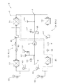
温度調整装置Mは、図2に示すように、二系統の熱媒体循環回路Cc,Ch、即ち、圧縮機5を共通にした第一冷凍サイクルCcc(熱媒体循環回路Cc)と第二冷凍サイクルChc(熱媒体循環回路Ch)備える。この場合、第一冷凍サイクルCccは冷却側となり、第二冷凍サイクルChcは加熱側となる。第一冷凍サイクルCccは、圧縮機5の吐出口→分流部P→第一調整弁(電子膨張弁)43→凝縮器17→電子膨張弁45→ヘッダ41c→第一熱交換部2c(第一チューブ構成部4c…)→合流部42c→合流部J→圧縮機5の吸込口の経路で冷媒(熱媒体)Kが循環する。第二冷凍サイクルChcは、圧縮機5の吐出口→分流部P→第二調整弁(電子膨張弁)46→ヘッダ41h→第二熱交換部2h(第二チューブ構成部4h…)→合流部42h→電子膨張弁47→蒸発器18→合流部J→圧縮機5の吸込口の経路で冷媒(熱媒)Kが循環する。図3は、温度調整装置Mをより具体化した回路で示したものであり、51,54,59は圧力ゲージ、52,56は圧力スイッチ、53,57は膨張弁、55,60はストレーナ、58はアキュムレータをそれぞれ示す。なお、図3において、図2と同一部分には同一符号を付してその構成を明確にした。   As shown in FIG. 2, the temperature adjusting device M includes two heat medium circulation circuits Cc and Ch, that is, a first refrigeration cycle Ccc (heat medium circulation circuit Cc) and a second refrigeration cycle that share the compressor 5. Chc (heat medium circulation circuit Ch) is provided. In this case, the first refrigeration cycle Ccc is on the cooling side, and the second refrigeration cycle Chc is on the heating side. The first refrigeration cycle Ccc includes a discharge port of the compressor 5 → a diversion part P → a first adjustment valve (electronic expansion valve) 43 → a condenser 17 → an electronic expansion valve 45 → a header 41 c → a first heat exchange part 2 c (first Tube constituent part 4 c...) → merging part 42 c → merging part J → refrigerant (heat medium) K circulates in the path of the suction port of the compressor 5. The second refrigeration cycle Chc is composed of a discharge port of the compressor 5 → a diverter P → a second adjustment valve (electronic expansion valve) 46 → a header 41 h → a second heat exchange unit 2 h (second tube component 4 h...) The refrigerant (heat medium) K circulates through the path of 42h → electronic expansion valve 47 → evaporator 18 → confluence portion J → suction port of the compressor 5. FIG. 3 shows a more specific circuit of the temperature adjusting device M. Reference numerals 51, 54 and 59 are pressure gauges, 52 and 56 are pressure switches, 53 and 57 are expansion valves, 55 and 60 are strainers, Reference numeral 58 denotes an accumulator. In FIG. 3, the same components as those in FIG.

このように、二系統の熱媒体循環回路Cc,Chを、圧縮機5を共通にした第一冷凍サイクルCccと第二冷凍サイクルChcにより構成し、また、熱交換用流体Wに、送風ファン6により送られる空気Aを適用するため、空気Aの温度を調整するための最良な温度調整装置Mを得ることができるとともに、第一熱交換部2c及び第二熱交換部2hを含む熱交換ユニット1を一体に構成し、この熱交換ユニット1を熱交換通路R内に配設して熱交換処理部Sを構成するため、熱交換ユニット1における各種作用効果を享受できる最適な温度調整装置Mを得ることができる。   In this way, the two heat medium circulation circuits Cc and Ch are configured by the first refrigeration cycle Ccc and the second refrigeration cycle Chc that share the compressor 5, and the heat exchange fluid W is supplied with the blower fan 6. In order to apply the air A sent by the above, the best temperature adjustment device M for adjusting the temperature of the air A can be obtained, and the heat exchange unit including the first heat exchange part 2c and the second heat exchange part 2h 1 is integrally formed, and the heat exchange unit 1 is disposed in the heat exchange passage R to form the heat exchange processing section S. Therefore, the optimum temperature adjustment device M that can enjoy various effects in the heat exchange unit 1 Can be obtained.

次に、本実施形態に係る熱交換ユニット1の機能を含む温度調整装置Mの動作について、図1〜図5を参照して説明する。   Next, operation | movement of the temperature control apparatus M including the function of the heat exchange unit 1 which concerns on this embodiment is demonstrated with reference to FIGS.

まず、目標温度(空気吹出口11ueから吹き出す空気Aの温度)が設定されることにより、予め設定された出力条件により分流部Pの分流比率が、設定された分流比率になるように、第一冷凍サイクルCcc(冷却側)における第一調整弁43と第二冷凍サイクルChc(加熱側)における第二調整弁46の開度がセットされる。   First, the target temperature (the temperature of the air A blown out from the air outlet 11ue) is set, so that the diversion ratio of the diversion part P becomes the set diversion ratio according to the preset output conditions. The opening degrees of the first adjustment valve 43 in the refrigeration cycle Ccc (cooling side) and the second adjustment valve 46 in the second refrigeration cycle Chc (heating side) are set.

一方、温度調整装置Mの運転が開始すれば、温度センサ20により空気吹出口11ueから吹き出す空気Aの温度が検出され、コントローラ19に付与される。これにより、コントローラ19では、付与された空気Aの検出温度が、予め設定した目標温度となるように、圧縮機5を含む第一冷凍サイクルCcc及び第二冷凍サイクルChcをフィードバック制御する。この際、運転開始後、目標温度に達するまでは、第一調整弁43及び第二調整弁46も制御される。これにより、予め設定されたプログラムに従って分流比率が最適な分流比率になるように設定される。そして、目標温度に達した後は、第一調整弁43及び第二調整弁46は固定されるとともに、第一冷凍サイクルCcc及び第二冷凍サイクルChcに対しては通常のフィードバック制御が行われる。   On the other hand, when the operation of the temperature adjusting device M starts, the temperature of the air A blown out from the air outlet 11 ue is detected by the temperature sensor 20 and applied to the controller 19. Thereby, the controller 19 performs feedback control of the first refrigeration cycle Ccc and the second refrigeration cycle Chc including the compressor 5 so that the detected temperature of the applied air A becomes a preset target temperature. At this time, the first regulating valve 43 and the second regulating valve 46 are also controlled until the target temperature is reached after the operation is started. Thus, the diversion ratio is set to an optimum diversion ratio according to a preset program. After reaching the target temperature, the first adjustment valve 43 and the second adjustment valve 46 are fixed, and normal feedback control is performed on the first refrigeration cycle Ccc and the second refrigeration cycle Chc.

また、図1に示す空気制御処理室11uでは、送風ファン13の作動により空気(外気)Aが吸込フィルタ16を通して吸い込まれ、前通気ダクト14内を通過する際に冷却器(蒸発器)17により冷却されるとともに、加熱器(凝縮器)18により加熱される。これにより、空気Aに対する温度調整が行われる。そして、温度調整された空気Aは送風ファン13を通り、更に後通気ダクト15を通して被空調空間に供給される。   Further, in the air control processing chamber 11 u shown in FIG. 1, air (outside air) A is sucked through the suction filter 16 by the operation of the blower fan 13 and is passed by the cooler (evaporator) 17 when passing through the front ventilation duct 14. While being cooled, it is heated by a heater (condenser) 18. Thereby, temperature adjustment with respect to the air A is performed. The temperature-adjusted air A passes through the blower fan 13 and is further supplied to the air-conditioned space through the rear ventilation duct 15.

他方、放熱処理室11dでは、送風ファン6の作動により空気Aが吸込フィルタ22を通して吸い込まれ、通気ダクト21内に配した本実施形態に係る熱交換ユニット1を通過することにより熱交換が行われる。具体的には、各フィン3…の面内に混在する第一チューブ構成部4c…により構成される第一熱交換部(蒸発器)2cによる吸熱が行われるとともに、各フィン3…の面内に混在する第二チューブ構成部4h…により構成される第二熱交換部(凝縮器)2hの放熱が行われる。そして、通気ダクト21内を通過することにより熱交換された空気Aは、空気吹出口11deから外部に排出される。   On the other hand, in the heat radiation processing chamber 11d, air A is sucked through the suction filter 22 by the operation of the blower fan 6, and heat exchange is performed by passing through the heat exchange unit 1 according to the present embodiment disposed in the ventilation duct 21. . Specifically, heat is absorbed by the first heat exchanging part (evaporator) 2c configured by the first tube constituent parts 4c ... mixed in the plane of the fins 3 ..., and the in-plane of the fins 3 ... The second heat exchanging part (condenser) 2h configured by the second tube constituent parts 4h. And the air A heat-exchanged by passing the inside of the ventilation duct 21 is discharged | emitted outside from the air blower outlet 11de.

この際、各第一チューブ構成部4c…と各第二チューブ構成部4h…は、各第一チューブ構成部4c単位及び各第二チューブ構成部4h単位で交互に配されるため、図5に示すように、各第一チューブ構成部4c…と各第二チューブ構成部4h…間は、フィン3…自体の熱伝導を直接利用した相互の熱交換が行われる。図5中、矢印Fchは、第一チューブ構成部4cによる第二チューブ構成部4hに対する冷却作用、矢印Fhcは、第二チューブ構成部4hによる第一チューブ構成部4cに対する加熱作用をイメージ的に示す。   At this time, the first tube constituent parts 4c and the second tube constituent parts 4h are alternately arranged in units of the first tube constituent parts 4c and in units of the second tube constituent parts 4h. As shown, the heat exchange between the first tube components 4c and the second tube components 4h is performed by directly using the heat conduction of the fins 3 themselves. In FIG. 5, the arrow Fch shows the cooling action with respect to the second tube constituent part 4h by the first tube constituent part 4c, and the arrow Fhc shows the heating action with respect to the first tube constituent part 4c by the second tube constituent part 4h. .

このように、本実施形態に係る熱交換ユニット1によれば、フィン3…自体の熱伝導を直接利用した第一熱交換部2cと第二熱交換部2h間の熱交換により更なる冷却効率及び加熱効率の向上に寄与できる。しかも、寒冷地で使用し、第二熱交換部2cに凍結の可能性がある環境下であってもフィン3…を介した熱伝導により凍結防止を図ることができる。また、第一熱交換部2c又は第二熱交換部2hの一方の使用を100〔%〕又はそれに近い状態で運転し、他方をほとんど使用しない場合であっても、第一熱交換部2c及び第二熱交換部2hの双方に共通に用いる複数の配列したフィン3…の全体を常時使用できるため、部品の有効利用に寄与できる。これにより、全体の加熱冷却能力及び加熱冷却効率を向上させることができるとともに、一方において、全体の加熱冷却能力を同等にする場合には、フィン3…のサイズダウンを図れるため、熱交換ユニット1の更なる小型化に寄与できる。   Thus, according to the heat exchange unit 1 according to the present embodiment, further cooling efficiency is achieved by heat exchange between the first heat exchange unit 2c and the second heat exchange unit 2h that directly use the heat conduction of the fins 3 itself. And it can contribute to the improvement of heating efficiency. In addition, even in an environment where the second heat exchanging portion 2c is used in a cold region and may be frozen, it is possible to prevent freezing by heat conduction through the fins 3. In addition, even when one of the first heat exchange unit 2c and the second heat exchange unit 2h is operated at 100% or close to it and the other is hardly used, the first heat exchange unit 2c and Since the whole of the plurality of arranged fins 3... Commonly used for both of the second heat exchanging parts 2h can be used at all times, it can contribute to the effective use of components. As a result, the overall heating / cooling capacity and heating / cooling efficiency can be improved. On the other hand, when the overall heating / cooling capacity is made equal, the size of the fins 3... Can be reduced. This can contribute to further downsizing of the product.

他方、図6及び図7には、本実施形態に係る熱交換ユニット1の参考例を示す。図1〜図5の熱交換ユニット1は、各第一チューブ構成部4c…と各第二チューブ構成部4h…を、第一チューブ構成部4c…単位及び第二チューブ構成部4h…単位で交互に配置した場合を示したが、図6及び図7の参考例は、各第一チューブ構成部4c…と各第二チューブ構成部4h…を、任意の数量を配列させた第一チューブ構成部グループ4cg…単位及び任意の数量を配列させた第二チューブ構成部グループ4hg…単位で交互に配置した場合を示す。図6は、主チューブ部材4o…を4列に配するため、1列目と3列目の全主チューブ部材4o…を第二チューブ構成部4h…に用いた第二チューブ構成部グループ4hg…とし、2列目と4列目の全主チューブ部材4o…を第一チューブ構成部4c…に用いた第一チューブ構成部グループ4cg…としたものである。この場合であっても、各フィン3…の上流側エリアZuと下流側エリアZdにそれぞれ第一チューブ構成部4c…と各第二チューブ構成部4h…が混在することになる。また、図7は、1列目と4列目の全主チューブ部材4o…を第二チューブ構成部4h…に用いた第二チューブ構成部グループ4hg…とし、2列目と3列目の全主チューブ部材4o…を第一チューブ構成部4c…に用いた第一チューブ構成部グループ4cg…としたものである。この場合であっても、各フィン3…の上流側エリアZuと下流側エリアZdにそれぞれ第一チューブ構成部4c…と各第二チューブ構成部4h…が混在することになる。   On the other hand, in FIG.6 and FIG.7, the reference example of the heat exchange unit 1 which concerns on this embodiment is shown. The heat exchange unit 1 of FIGS. 1-5 alternates each 1st tube structure part 4c ... and 2nd tube structure part 4h ... by the 1st tube structure part 4c ... unit and the 2nd tube structure part 4h ... unit. 6 and FIG. 7, the first tube constituent parts in which the first tube constituent parts 4 c... And the second tube constituent parts 4 h. The group 4cg... Shows a case where the units are arranged alternately in units of second tube constituent groups 4hg. In FIG. 6, in order to arrange the main tube members 4o in four rows, the second tube component group 4hg in which all the main tube members 4o in the first and third rows are used as the second tube component 4h. In this case, the first tube constituent group 4cg... In which all the main tube members 4o in the second row and the fourth row are used as the first tube constituent portions 4c. Even in this case, the first tube component 4c and the second tube component 4h are mixed in the upstream area Zu and the downstream area Zd of the fins 3 respectively. Further, FIG. 7 shows that all the main tube members 4o in the first row and the fourth row are second tube component groups 4hg ... used in the second tube component 4h, ... The main tube members 4o are used as the first tube constituent groups 4cg used in the first tube constituent parts 4c. Even in this case, the first tube component 4c and the second tube component 4h are mixed in the upstream area Zu and the downstream area Zd of the fins 3 respectively.

このように、本実施形態に係る熱交換ユニット1では、各第一チューブ構成部4c…と各第二チューブ構成部4h…を、第一チューブ構成部4c…単位及び第二チューブ構成部4h…単位で交互に配置できるとともに、任意の数量を配列させた第一チューブ構成部グループ4cg…単位及び任意の数量を配列させた第二チューブ構成部グループ4hg…単位で交互に配置できるなど、用途や目的に応じた各種レイアウト形態を選択した設計が可能となる。したがって、熱交換ユニット1の設計自由度の向上、更には設計の最適化を容易に実現でき、多様性及び多機能性に優れた熱交換ユニット1を得ることができる。   As described above, in the heat exchange unit 1 according to the present embodiment, each of the first tube constituent parts 4c and each of the second tube constituent parts 4h is replaced by a first tube constituent part 4c ... unit and a second tube constituent part 4h. The first tube component group 4cg in which arbitrary quantities are arranged and the second tube component group 4hg in which arbitrary quantities are arranged can be alternately arranged in units, It is possible to design by selecting various layout forms according to the purpose. Therefore, improvement in design flexibility of the heat exchange unit 1 and optimization of the design can be easily realized, and the heat exchange unit 1 excellent in diversity and multifunctionality can be obtained.

次に、本発明の変更実施形態に係る温度調整装置Mについて、図8を参照して説明する。図8に示す温度調整装置Mは、空気制御処理室11uに配設した蒸発器(冷却器)17と凝縮器(加熱器)18を、熱交換ユニット1により構成したものである。即ち、図1〜図5に示した温度調整装置Mでは、放熱処理室11dに配設した熱交換ユニット1により、第一熱交換部(蒸発器(吸熱器))2cと第二熱交換部(凝縮器(放熱器))2hを一体に構成したものであるが、図8に示す温度調整装置Mでは、図1に示す第一熱交換部2cを蒸発器17として使用し、図1に示す第二熱交換部2hを凝縮器18として使用するものである。この場合、空気制御処理室11uに用いる熱交換ユニット1も、図1に示した温度調整装置Mにおける放熱処理室11dに配設した熱交換ユニット1と同様の作用効果を享受できるとともに、特に、放熱処理室11dと空気制御処理室11uの双方に熱交換ユニット1,1を備えるため、ハウジング11の前後方向のサイズをより短くできるなど、更なる小型化に寄与できる。このように、熱交換ユニット1は、各種用途に適用できるが、冷却器を除湿用として使用するなど、他の機能が付加される場合には、必ずしも有効とは言えない場合もあるため、用途や目的に応じて使用の可否を選択する必要がある。   Next, a temperature adjustment device M according to a modified embodiment of the present invention will be described with reference to FIG. A temperature adjusting device M shown in FIG. 8 is configured by an evaporator (cooler) 17 and a condenser (heater) 18 disposed in the air control processing chamber 11u by a heat exchange unit 1. That is, in the temperature adjusting device M shown in FIGS. 1 to 5, the heat exchange unit 1 disposed in the heat radiation processing chamber 11 d causes the first heat exchange unit (evaporator (heat absorber)) 2 c and the second heat exchange unit. (Condenser (heat radiator)) 2h is configured integrally, but in the temperature adjusting device M shown in FIG. 8, the first heat exchanging part 2c shown in FIG. 1 is used as the evaporator 17, and FIG. The second heat exchange part 2h shown is used as the condenser 18. In this case, the heat exchange unit 1 used for the air control processing chamber 11u can also enjoy the same effects as the heat exchange unit 1 disposed in the heat radiation processing chamber 11d in the temperature adjusting device M shown in FIG. Since both the heat radiation processing chamber 11d and the air control processing chamber 11u are provided with the heat exchange units 1 and 1, the size of the housing 11 in the front-rear direction can be further shortened, which can contribute to further miniaturization. As described above, the heat exchange unit 1 can be applied to various uses. However, when other functions are added such as using a cooler for dehumidification, the heat exchange unit 1 may not always be effective. It is necessary to select whether or not it can be used according to the purpose.

以上、好適実施形態(変更実施形態)について詳細に説明したが、本発明は、このような実施形態に限定されるものではなく、細部の構成,形状,素材,数量,手法等において、本発明の要旨を逸脱しない範囲で、任意に変更,追加,削除することができる。   The preferred embodiment (modified embodiment) has been described in detail above. However, the present invention is not limited to such an embodiment, and the present invention is not limited to the detailed configuration, shape, material, quantity, technique, and the like. Any change, addition, or deletion can be made without departing from the scope of the above.

例えば、各第一チューブ構成部4c…の端部同士及び各第二チューブ構成部4h…の端部同士をU形接続チューブ4j…により接続した場合を示したが、必ずしもこのような接続態様に限定されるものではない。したがって、U形接続チューブ4j…を用いることなく、全部の第一チューブ構成部4c…を共通のヘッダ41cにそれぞれ接続したり、全部の第二チューブ構成部4h…を共通のヘッダ41hにそれぞれ接続してもよい。また、一部の第一チューブ構成部4c…の端部同士のみをU形接続チューブ4j…に接続したり、一部の第二チューブ構成部4h…の端部同士のみをU形接続チューブ4j…に接続してもよいし、さらに、各第一チューブ構成部4c…と各第二チューブ構成部4h…の接続態様を異ならせてもよい。一方、温度調整装置Mは、二系統の熱媒体循環回路Cc,Chとして、圧縮機5を共通にした第一冷凍サイクルCccと第二冷凍サイクルChcにより構成した場合を示したが、二系統の熱媒体循環回路Cc,Chは、必ずしも冷凍サイクルに限定されるものではない。したがって、熱媒体Kには、例示の冷媒をはじめ、各種流体が含まれる。また、一方の熱媒体循環回路Ccと他方の熱媒体循環回路Chに用いる熱媒体Kは同一であってもよいし異なっていてもよい。   For example, although the case where the edge parts of each 1st tube structure part 4c ... and the edge parts of each 2nd tube structure part 4h ... were connected by the U-shaped connection tube 4j ... was shown, it is not necessarily in such a connection aspect. It is not limited. Therefore, without using the U-shaped connection tubes 4j, all the first tube components 4c are connected to the common header 41c, or all the second tube components 4h are connected to the common header 41h, respectively. May be. Further, only the ends of some of the first tube constituent parts 4c ... are connected to the U-shaped connecting tube 4j ..., or only the ends of some of the second tube constituting parts 4h ... are connected to the U-shaped connecting tube 4j. May be connected to each other, and the connection modes of the first tube constituent portions 4c and the second tube constituent portions 4h may be different. On the other hand, the temperature adjusting device M shows a case where the two heat medium circulation circuits Cc and Ch are configured by the first refrigeration cycle Ccc and the second refrigeration cycle Chc having the compressor 5 in common. The heat medium circulation circuits Cc and Ch are not necessarily limited to the refrigeration cycle. Therefore, the heat medium K includes various fluids including the illustrated refrigerant. Further, the heat medium K used in one heat medium circuit Cc and the other heat medium circuit Ch may be the same or different.

本発明に係る熱交換ユニットは、例示の温度調整装置をはじめ、二系統の熱媒体と熱交換用流体との熱交換を行う各種温度調整装置に利用できる。また、温度調整装置は、空気に対する温度調整をはじめ、ガス,水,溶液等の各種流体の温度を調整する各種冷熱機器に利用できる。   The heat exchanging unit according to the present invention can be used in various temperature adjusting devices that perform heat exchange between two systems of heat medium and a heat exchanging fluid, including the exemplary temperature adjusting device. The temperature adjusting device can be used for various types of cooling and heating equipment that adjusts the temperature of various fluids such as gas, water, and solution, as well as temperature adjustment for air.

1:熱交換ユニット,2c:第一熱交換部,,2h:第二熱交換部,3…:フィン,4c…:第一チューブ構成部,4h…:第二チューブ構成部,5:圧縮機,6:送風ファン,M:温度調整装置,K:熱媒体,Cc:一方の熱媒体循環回路,Ch:他方の熱媒体循環回路,Ccc:第一冷凍サイクル,Chc:第二冷凍サイクル,A:空気,R:熱交換通路,S:熱交換処理部   1: heat exchange unit, 2c: first heat exchange part, 2h: second heat exchange part, 3 ...: fin, 4c ...: first tube constituent part, 4h ...: second tube constituent part, 5: compressor , 6: blower fan, M: temperature adjusting device, K: heat medium, Cc: one heat medium circuit, Ch: other heat medium circuit, Ccc: first refrigeration cycle, Chc: second refrigeration cycle, A : Air, R: Heat exchange passage, S: Heat exchange processing section

Claims (6)

熱媒体が流通循環する二系統の熱媒体循環回路における一方の熱媒体循環回路の熱媒体により冷却を行う第一熱交換部と他方の熱媒体循環回路の熱媒体により加熱を行う第二熱交換部を含むフィンアンドチューブ方式により構成した熱交換ユニットであって、前記第一熱交換部及び前記第二熱交換部に共通に用いる複数の配列したフィンと、前記第一熱交換部に対応し、かつ前記各フィンに貫通する複数の第一チューブ構成部と、前記第二熱交換部に対応し、かつ前記各フィンに貫通する複数の第二チューブ構成部とを備え、前記各フィンに貫通する前記第一チューブ構成部と前記第二チューブ構成部を、横方向に交互に配置するとともに、縦方向に交互に配置することにより、一体に構成してなることを特徴とする熱交換ユニット。   In the two heat medium circulation circuits in which the heat medium flows and circulates, the first heat exchange section that cools by the heat medium of one heat medium circulation circuit and the second heat exchange that heats by the heat medium of the other heat medium circulation circuit A heat exchange unit configured by a fin-and-tube system including a plurality of fins arranged in common and used for the first heat exchange unit and the second heat exchange unit, and corresponding to the first heat exchange unit. And a plurality of first tube constituent parts penetrating the fins, and a plurality of second tube constituent parts corresponding to the second heat exchanging parts and penetrating the fins, and penetrating the fins. The heat exchange unit, wherein the first tube component and the second tube component are alternately arranged in the horizontal direction and alternately arranged in the vertical direction. 前記各第一チューブ構成部の端部同士及び前記各第二チューブ構成部の端部同士は、U形接続チューブにより接続することを特徴とする請求項1記載の熱交換ユニット。   2. The heat exchange unit according to claim 1, wherein ends of the first tube constituent portions and end portions of the second tube constituent portions are connected by a U-shaped connecting tube. 前記各第一チューブ構成部と前記各第二チューブ構成部は、第一チューブ構成部単位及び第二チューブ構成部単位で交互に配置することを特徴とする請求項1又は2記載の熱交換ユニット。   3. The heat exchange unit according to claim 1, wherein the first tube components and the second tube components are alternately arranged in units of the first tube component and the second tube component. . 熱媒体が流通循環する二系統の熱媒体循環回路における一方の熱媒体循環回路の熱媒体により冷却を行う第一熱交換部と他方の熱媒体循環回路の熱媒体により加熱を行う第二熱交換部を含むフィンアンドチューブ方式により構成した熱交換ユニットを、熱交換用流体が流通する共通の熱交換通路内に配設した熱交換処理部を備える温度調整装置であって、前記第一熱交換部及び前記第二熱交換部に共通に用いる複数の配列したフィンと、前記第一熱交換部に対応し、かつ前記各フィンに貫通する複数の第一チューブ構成部と、前記第二熱交換部に対応し、かつ前記各フィンに貫通する複数の第二チューブ構成部とを備え、前記各フィンに貫通する前記第一チューブ構成部と前記第二チューブ構成部を、横方向に交互に配置するとともに、縦方向に交互に配置することにより、一体に構成してなる熱交換ユニットを、前記熱交換通路内に配設した熱交換処理部を備えることを特徴とする温度調整装置。   In the two heat medium circulation circuits in which the heat medium flows and circulates, the first heat exchange section that cools by the heat medium of one heat medium circulation circuit and the second heat exchange that heats by the heat medium of the other heat medium circulation circuit A heat regulation unit including a heat exchange processing unit arranged in a common heat exchange passage through which a heat exchange fluid circulates a heat exchange unit configured by a fin-and-tube system including a part, wherein the first heat exchange And a plurality of arranged fins used in common for the second heat exchange section, a plurality of first tube components corresponding to the first heat exchange section and penetrating through the fins, and the second heat exchange A plurality of second tube constituent parts that pass through the fins, and the first tube constituent parts and the second tube constituent parts that pass through the fins are arranged alternately in the lateral direction. And vertical The by alternately arranging, temperature adjustment device, characterized in that the heat exchange unit formed by integrally formed, comprising the heat exchanger the heat exchanger unit which is disposed in the passage. 前記二系統の熱媒体循環回路は、圧縮機を共通にした第一冷凍サイクルと第二冷凍サイクルにより構成することを特徴とする請求項4記載の温度調整装置。   5. The temperature adjusting device according to claim 4, wherein the two heat medium circulation circuits are constituted by a first refrigeration cycle and a second refrigeration cycle having a common compressor. 前記熱交換用流体は、送風ファンにより送られる空気であることを特徴とする請求項4又は5記載の温度調整装置。   6. The temperature adjusting device according to claim 4, wherein the heat exchange fluid is air sent by a blower fan.
JP2011185650A 2011-08-29 2011-08-29 Heat exchange unit and temperature control device Active JP5817058B2 (en)

Priority Applications (1)

Application Number Priority Date Filing Date Title
JP2011185650A JP5817058B2 (en) 2011-08-29 2011-08-29 Heat exchange unit and temperature control device

Applications Claiming Priority (1)

Application Number Priority Date Filing Date Title
JP2011185650A JP5817058B2 (en) 2011-08-29 2011-08-29 Heat exchange unit and temperature control device

Publications (3)

Publication Number Publication Date
JP2013047578A JP2013047578A (en) 2013-03-07
JP2013047578A5 JP2013047578A5 (en) 2014-07-24
JP5817058B2 true JP5817058B2 (en) 2015-11-18

Family

ID=48010655

Family Applications (1)

Application Number Title Priority Date Filing Date
JP2011185650A Active JP5817058B2 (en) 2011-08-29 2011-08-29 Heat exchange unit and temperature control device

Country Status (1)

Country Link
JP (1) JP5817058B2 (en)

Families Citing this family (1)

* Cited by examiner, † Cited by third party
Publication number Priority date Publication date Assignee Title
JP6496346B2 (en) * 2017-04-18 2019-04-03 株式会社東京精密 Temperature control device

Family Cites Families (5)

* Cited by examiner, † Cited by third party
Publication number Priority date Publication date Assignee Title
JPS52166345U (en) * 1976-06-10 1977-12-16
JP2001165527A (en) * 1999-12-08 2001-06-22 Hitachi Ltd Air conditioner
JP2004053236A (en) * 2002-07-22 2004-02-19 Kiyoshi Yanagimachi Condenser for chiller
JP2008309465A (en) * 2007-05-11 2008-12-25 Orion Mach Co Ltd Temperature control device
JP2009006126A (en) * 2007-05-31 2009-01-15 Panasonic Corp Clothing dryer

Also Published As

Publication number Publication date
JP2013047578A (en) 2013-03-07

Similar Documents

Publication Publication Date Title
JP5538503B2 (en) Outdoor unit and refrigeration cycle apparatus
JP6433582B2 (en) Heat source unit
WO2012073746A1 (en) Integrated air-conditioning system, and internal air unit, external air unit, and laminated body, thereof
JP6411238B2 (en) Air conditioner
JP6119141B2 (en) Air conditioning system
JP2010108359A (en) Air conditioning system for server room
JP2014206330A (en) Chiller device
JP6339945B2 (en) Air conditioner
JP2007139262A (en) Water-cooled heat pump type air conditioner
JP5775185B2 (en) Heat exchange coil and air conditioner
JP2008075988A (en) Composite heat radiating member, cooling unit, cooling system and cooling system assembly
JP6727398B2 (en) Heat exchanger and air conditioner
JP5817058B2 (en) Heat exchange unit and temperature control device
GB2546202A (en) Indoor unit for air conditioning device
KR20070059911A (en) Liquid to air heater and cooler
KR100784845B1 (en) Air conditioner for cooling and heating having multiple 4-way valve
JP2009198141A (en) Heat exchange apparatus
WO2016151655A1 (en) Air conditioning device and method for determining performance of same
JP2020098082A (en) Air conditioner
JP5365682B2 (en) Air conditioner and control method of air conditioner
CN205536252U (en) Cooling and heating type air conditioner and single cooling type air conditioner
KR102076679B1 (en) A heat exchanger and a natural coolant circulation air conditioner
JP2018128232A (en) Heat pump unit
US11378286B2 (en) Outdoor unit
JP6873194B2 (en) Air conditioner

Legal Events

Date Code Title Description
A521 Request for written amendment filed

Free format text: JAPANESE INTERMEDIATE CODE: A523

Effective date: 20140606

A621 Written request for application examination

Free format text: JAPANESE INTERMEDIATE CODE: A621

Effective date: 20140606

A977 Report on retrieval

Free format text: JAPANESE INTERMEDIATE CODE: A971007

Effective date: 20150212

A131 Notification of reasons for refusal

Free format text: JAPANESE INTERMEDIATE CODE: A131

Effective date: 20150218

A521 Request for written amendment filed

Free format text: JAPANESE INTERMEDIATE CODE: A523

Effective date: 20150415

TRDD Decision of grant or rejection written
A01 Written decision to grant a patent or to grant a registration (utility model)

Free format text: JAPANESE INTERMEDIATE CODE: A01

Effective date: 20150826

A61 First payment of annual fees (during grant procedure)

Free format text: JAPANESE INTERMEDIATE CODE: A61

Effective date: 20150910

R150 Certificate of patent or registration of utility model

Ref document number: 5817058

Country of ref document: JP

Free format text: JAPANESE INTERMEDIATE CODE: R150

R250 Receipt of annual fees

Free format text: JAPANESE INTERMEDIATE CODE: R250

R250 Receipt of annual fees

Free format text: JAPANESE INTERMEDIATE CODE: R250

R250 Receipt of annual fees

Free format text: JAPANESE INTERMEDIATE CODE: R250

R250 Receipt of annual fees

Free format text: JAPANESE INTERMEDIATE CODE: R250

R250 Receipt of annual fees

Free format text: JAPANESE INTERMEDIATE CODE: R250

R250 Receipt of annual fees

Free format text: JAPANESE INTERMEDIATE CODE: R250