JP6432876B2 - Lifting device, stacker crane and height holding method of lifting platform - Google Patents
Lifting device, stacker crane and height holding method of lifting platform Download PDFInfo
- Publication number
- JP6432876B2 JP6432876B2 JP2014163670A JP2014163670A JP6432876B2 JP 6432876 B2 JP6432876 B2 JP 6432876B2 JP 2014163670 A JP2014163670 A JP 2014163670A JP 2014163670 A JP2014163670 A JP 2014163670A JP 6432876 B2 JP6432876 B2 JP 6432876B2
- Authority
- JP
- Japan
- Prior art keywords
- lifting platform
- lifting
- servo motor
- height
- platform
- Prior art date
- Legal status (The legal status is an assumption and is not a legal conclusion. Google has not performed a legal analysis and makes no representation as to the accuracy of the status listed.)
- Active
Links
- 238000000034 method Methods 0.000 title claims description 10
- 230000003028 elevating effect Effects 0.000 claims description 4
- 230000000694 effects Effects 0.000 description 3
- 238000010586 diagram Methods 0.000 description 1
- 238000012423 maintenance Methods 0.000 description 1
- 230000000717 retained effect Effects 0.000 description 1
- 230000000630 rising effect Effects 0.000 description 1
Images


Landscapes
- Engineering & Computer Science (AREA)
- Warehouses Or Storage Devices (AREA)
- Transportation (AREA)
- Structural Engineering (AREA)
- Mechanical Engineering (AREA)
- Civil Engineering (AREA)
- Life Sciences & Earth Sciences (AREA)
- Geology (AREA)
- Forklifts And Lifting Vehicles (AREA)
- Control And Safety Of Cranes (AREA)
Description
この発明は、昇降装置とスタッカークレーンとに関し、特に昇降台の高さの保持に関する。 The present invention relates to an elevating device and a stacker crane, and more particularly to maintaining the height of an elevating platform.
特許文献1(特許4962535)は、サーボモータにより昇降台を昇降させるスタッカークレーンを開示している。ここでサーボモータ自体により昇降台の高さを保持し、ブレーキを設けないようにすると、スタッカークレーンを軽量化できる。 Patent Document 1 (Patent 4962535) discloses a stacker crane that raises and lowers a lifting platform using a servo motor. Here, if the height of the lifting platform is maintained by the servo motor itself and no brake is provided, the stacker crane can be reduced in weight.
発明者は、昇降台を固定するブレーキも、昇降台の重量とバランスするカウンターウェイトも設けないと、昇降台の停止後に、サーボモータのトルクが定格トルク近くまで増加し、過負荷エラーを起こすことがあることを見出した。そこでこの発明の課題は、昇降台が停止し、その高さをサーボモータのトルクにより保持する際に、トルクが増加して過負荷エラーが生じないようにすることにある。 If the inventor does not provide a brake for fixing the lifting platform or a counterweight that balances the weight of the lifting platform, the servo motor torque will increase to near the rated torque after the lifting platform stops, causing an overload error. Found that there is. Accordingly, an object of the present invention is to prevent an overload error due to an increase in torque when the elevator platform is stopped and its height is held by the torque of the servo motor.
この発明は、昇降台を昇降させる機構部と、機構部を駆動することによって昇降台を昇降させるサーボモータ、とを備えている昇降装置であって、
昇降台の昇降を停止させて高さを保持する際に、昇降台の停止後にサーボモータにより昇降台を所定高さだけ下降させるようにサーボモータを制御する、制御部を備えていることを特徴とする。
The present invention is a lifting device comprising a mechanism unit that raises and lowers a lifting platform, and a servo motor that raises and lowers the lifting platform by driving the mechanism unit,
When holding the height by stopping the lifting / lowering of the lifting platform, a control unit is provided for controlling the servo motor so that the lifting / lowering platform is lowered by a predetermined height by the servo motor after the lifting / lowering platform is stopped. And
またこの発明は、昇降台を昇降させる機構部と、機構部を駆動することによって昇降台を昇降させるサーボモータ、とを備えている昇降装置での、昇降台の高さ保持方法であって、
昇降台の昇降を停止させて高さを保持する際に、昇降台の停止後に、サーボモータにより昇降台を所定高さだけ下降させることを特徴とする。
Further, the present invention is a method for maintaining the height of a lifting platform in a lifting device including a mechanism that lifts and lowers the lifting platform, and a servo motor that lifts the lifting platform by driving the mechanism.
When holding the height by stopping the lifting / lowering of the lifting platform, the lifting / lowering platform is lowered by a predetermined height by a servo motor after the lifting / lowering platform is stopped.
発明者は以下のことを見出した。
・ 昇降台を上昇させて停止させたときでも、下降させて停止させたときでも、昇降台の高さの保持に必要なトルクは、停止の直前に昇降台は上昇していたか下降していたかで変化する。
・ 停止直前に昇降台が上昇していた場合、停止後にサーボモータのトルクが増加し、その後も高い値に保たれる。
・ 昇降台はサーボモータにより昇降するので、上昇して停止する場合でも、停止直前にオーバーシュートした後に下降することもある。また下降して停止する場合でも、停止直前にオーバーシュートした後に上昇することもある。
・ 停止直前に下降していた場合に保持トルクが小さくなることは、機構部から昇降台の下降に抵抗する力が加わり、停止後もこの力が保持されていることを示唆する。また停止直前に上昇していた場合に保持トルクが大きくなることは、機構部から昇降台の上昇に抵抗する力が加わり、停止後もこの力が保持されていることを示唆する。
・ 昇降台の停止後に、僅かな高さだけサーボモータにより下降させると、下降する高さが微小で、かつ昇降台の下降速度は僅かなので、昇降台がアンダーシュートすることはなく、昇降台は下降しながら停止する。
The inventor has found the following.
・ Whether the lifting platform was raised or lowered immediately before stopping, whether the lifting platform was raised and stopped, or lowered and stopped. It changes with.
・ If the platform is raised just before the stop, the servo motor torque will increase after the stop and will remain high after that.
-Since the elevator platform is moved up and down by the servo motor, even if it is raised and stopped, it may drop after overshooting just before stopping. Even when the vehicle descends and stops, it may rise after overshooting just before stopping.
-If the holding torque is reduced when it is lowered just before the stop, a force that resists the lowering of the lifting platform is applied from the mechanism part, and this force is maintained even after the stop. In addition, when the holding torque is increased immediately before stopping, a force that resists the lifting of the lifting platform is applied from the mechanism unit, and this force is maintained even after stopping.
・ After the lift is stopped, if it is lowered by a small amount by the servo motor, the height of the lift is very small, and the speed of the lift is low, so the lift does not undershoot. Stop while descending.
そこで、昇降台の停止後に、サーボモータにより昇降台を所定高さだけ下降させると、昇降台の高さの保持に必要なトルクが小さくなり、サーボモータの過負荷エラーを防止できる。なおこの明細書において、昇降装置に関する記載は、スタッカークレーンにも、昇降台の高さ保持方法にも当てはまる。 Therefore, when the elevator table is lowered by a predetermined height by the servo motor after the elevator table is stopped, the torque required to maintain the height of the elevator table is reduced, and an overload error of the servo motor can be prevented. In this specification, the description related to the lifting device applies to both the stacker crane and the height holding method of the lifting platform.
好ましくは、前記制御部は、昇降台の停止後にサーボモータのトルクを監視し、サーボモータのトルクが所定の閾値以上になると、昇降台を所定高さだけ下降させるように構成されている。トルクは例えばサーボモータの駆動電流により監視する。このようにして、昇降台が昇降を停止した後に、高さの保持に必要なトルクが増加すると、昇降台を下降させて、必要なトルクを小さくする。停止後に一律に昇降台を再下降させる場合に比べ、昇降台のサイクルタイムへの影響を小さくできる。 Preferably, the control unit is configured to monitor the torque of the servo motor after stopping the lifting platform, and to lower the lifting platform by a predetermined height when the torque of the servo motor exceeds a predetermined threshold. The torque is monitored by, for example, a servo motor drive current. In this way, when the torque necessary for maintaining the height increases after the lifting platform stops moving up and down, the lifting platform is lowered to reduce the required torque. Compared with the case where the lifting platform is uniformly lowered again after stopping, the influence of the lifting platform on the cycle time can be reduced.
好ましくは、機構部は、昇降台のカウンターウェイトも、機構部を固定するブレーキも備えず、サーボモータのトルクのみによって、昇降台の高さを保持するように構成されている。このようにすると、昇降装置は小型でかつ軽量になる。 Preferably, the mechanism unit is configured to hold the height of the lifting platform only by the torque of the servo motor without including the counterweight of the lifting platform and the brake for fixing the mechanism unit. In this way, the lifting device is small and lightweight.
例えば、この発明の昇降装置あるいは昇降台の高さ保持方法を、台車と、台車から上方へ起立するマストとを備えるスタッカークレーンに適用し、機構部をマストに収納して、昇降台をマストにそって昇降させる。するとスタッカークレーンの昇降台が停止した後の、サーボモータの過負荷エラーを防止できる。特に、カウンターウェイトも機構部を固定するブレーキも備えていない場合、軽量で小型のスタッカークレーンとなる。 For example, the lifting device or the method for maintaining the height of the lifting platform of the present invention is applied to a stacker crane including a carriage and a mast that stands upward from the carriage, the mechanism is stored in the mast, and the lifting platform is used as a mast. Raise and lower along. Then, an overload error of the servo motor after the elevator platform of the stacker crane stops can be prevented. In particular, when neither the counterweight nor the brake for fixing the mechanism portion is provided, a light and small stacker crane is obtained.
好ましくは、前記機構部は、マストの下部と上部とに取り付けられている上下の歯車と、上下の歯車に巻き掛けられているエンドレスの駆動媒体とを備え、サーボモータは、上下いずれかの歯車に接続されて、サーボモータからのトルクにより歯車を固定するように構成されている。このようにすると、カウンターウェイトもブレーキも無しに、昇降台の高さを保持できる。 Preferably, the mechanism section includes upper and lower gears attached to a lower portion and an upper portion of the mast, and an endless drive medium wound around the upper and lower gears, and the servo motor is one of the upper and lower gears. The gear is fixed by the torque from the servo motor. If it does in this way, the height of an elevator stand can be hold | maintained without a counterweight and a brake.
以下に本発明を実施するための最適実施例を示す。この発明の範囲は、特許請求の範囲の記載に基づき、明細書の記載とこの分野での周知技術とを参酌し、当業者の理解に従って定められるべきである。 In the following, an optimum embodiment for carrying out the present invention will be shown. The scope of the present invention should be determined according to the understanding of those skilled in the art based on the description of the scope of the claims, taking into account the description of the specification and well-known techniques in this field.
図1〜図4に、スタッカークレーン2を例に実施例の昇降装置を示す。なおこの発明は、天井走行車、固定のマストにそって昇降台を昇降させる昇降装置、等にも適用できる。図において、4は台車で走行車輪5を備え、6は例えば左右一対のマストで、連結部7により連結され、マスト6の本数は任意で、例えば1本でも良い。8は昇降台で、スカラアーム、スライドフォーク等の移載装置9を備え、昇降台8は例えばチェーン10によって支持されて昇降する。12はチェーン10のスプロケット、14は昇降用のサーボモータで、スプロケット12を回転させる。サーボモータ14は、マスト6の下部のスプロケットを駆動するが、上部のスプロケットを駆動しても良い。なおチェーン10に代えてベルト等を用い、スプロケット12に代えてギア等を用いても良い。またWは移載装置9上に載置された荷物である。
1 to 4 show an elevating apparatus according to an embodiment using the
スタッカークレーン2は、昇降台8のカウンターウェイトを有さず、これによって軽量化とマスト6の小型化を図っている。また摩擦等によりスプロケット12を固定する、電磁式あるいは機械式のブレーキを備えず、サーボモータ14によりスプロケット12を固定することにより、昇降台8を一定の高さに保持する。これによって、スタッカークレーン2をさらに軽量化している。なおカウンターウェイトを有する場合、あるいは電磁ブレーキ等を有する場合でも、サーボモータ14の出力トルクを昇降台8の位置の保持に用いる場合に、実施例は有効である。
The
実施例の適用範囲は、スタッカークレーン2に限らない。天井走行車は、台車と、昇降台を昇降させるホイストとを備え、このホイストでの昇降台の昇降用のサーボモータに、実施例を適用することができる。また台車を備えず、固定のマストに沿って昇降する昇降台を有する昇降装置等にも、実施例を適用することができる。
The application range of the embodiment is not limited to the
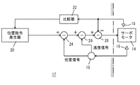
図2はサーボモータ14の制御部17を示し、15はトルクセンサで、サーボモータ14の駆動電流から、サーボモータ14の出力トルクを測定する。16はエンコーダで、差分器18はエンコーダ16の信号の時間当たりの差分から、サーボモータ14の回転に関する速度信号を求める。20は位置指令発生器で、昇降台の高さ位置の目標値を位置指令として発生し、停止時(昇降台高さの保持時)には高さ位置の目標値は一定である。また22は、サーボモータのトルクを閾値と比較する比較器である。速度指令発生器24は、位置指令とエンコーダ16から求めた高さ位置との誤差から速度指令を発生し、電流指令発生器26は、速度指令と差分器18により求めた速度信号との誤差から電流指令を発生し、サーボアンプ28は、電流指令とトルクセンサ15等により求めたモータ電流との差を解消するように、サーボモータ14へ電流を供給する。
FIG. 2 shows a
比較器22には、トルクセンサ15からサーボモータ14の駆動電流が入力されて、所定の閾値と比較する。なお駆動電流の代わりに、サーボモータ14の駆動電圧等を、出力トルクを表す信号として、用いても良い。比較器22は、昇降台が停止することにより動作を開始し、次の目標位置への昇降を開始すると動作を停止する。比較器22は、サーボモータ14の出力トルクが所定値以上になると、その旨の信号を位置指令発生器20に入力し、この信号に対して、位置指令発生器20は昇降台の高さ位置の目標値を所定高さだけ低下させて、サーボモータ14により昇降台を下降させる。なお所定高さは、下降後の昇降台の停止高さが許容範囲を下回らないように定め、例えば1mm〜5mm程度である。所定高さだけ昇降台を下降させた後に昇降台が停止すると、比較器22を再動作させても、させなくても良い。
The
昇降台の高さをサーボモータ14により保持すると、サーボモータ14の出力トルクが定格トルク近くまで増加することがあり、これはサーボモータ14の過負荷エラーを引き起こす。これに対して、サーボモータ14の出力トルクが定格トルク近くまで増加する前に、昇降台の位置を下降させると、昇降台の保持に必要なトルクが減少し、過負荷エラーは生じない。
If the height of the lifting platform is held by the
このことを図3により説明する。昇降台を上昇させて停止させたときでも、下降させて停止させたときでも、昇降台の高さの保持に必要なトルクは、停止の直前に昇降台は上昇していたか下降していたかで変化する。より詳細には、停止直前に昇降台が上昇していた場合、停止後数十m秒程度の時定数でサーボモータのトルクが増加し、昇降台の上昇動作に必要な程度のトルクあるいはそれ以上トルクに達して、その後も高い値に保たれる。 This will be described with reference to FIG. Whether the elevator is raised and stopped or lowered and stopped, the torque required to maintain the height of the elevator depends on whether the elevator was raised or lowered immediately before stopping. Change. More specifically, if the platform is raised immediately before stopping, the torque of the servo motor increases with a time constant of about several tens of milliseconds after the stop, and the torque required for the lifting operation of the platform is higher or higher. The torque is reached and remains high thereafter.
昇降台はサーボモータ14により昇降するので、上昇して停止する場合でも、停止直前にオーバーシュートした後に下降することもある。また下降して停止する場合でも、停止直前にオーバーシュートした後に上昇することもある。そして停止直前に上昇していた場合に昇降台の保持に必要なトルクは大きく、下降していた場合に保持トルクは小さい。次ぎに昇降台の保持トルクの大小は、上部のスプロケットにサーボモータを接続しても、下部のスプロケットにサーボモータを接続しても同じであるが、昇降台に荷物があると保持トルクは大きくなる。
Since the lifting platform is moved up and down by the
停止直前に下降していた場合に保持トルクが小さくなることは、昇降台とチェーン、スプロケット等から、下降に抵抗する力が加わり、停止後もこの力が保持されていることを示唆する。逆に、停止直前に上昇していた場合に保持トルクが大きくなることは、昇降台とチェーン、スプロケット等から、上昇に抵抗する力が加わり、停止後もこの力が保持されていることを示唆する。 A decrease in holding torque when the vehicle is descending immediately before stopping suggests that a force resisting descending is applied from the lifting platform, chain, sprocket, and the like, and this force is retained even after stopping. On the other hand, if the holding torque increases when it is lifted just before stopping, it indicates that a force that resists rising is applied from the lifting platform, chain, sprocket, etc., and this force is maintained even after stopping. To do.
実施例では、昇降台が停止直前に必ず下降するように制御するのではなく、昇降台が停止した後に、サーボモータの出力トルクを監視し、トルクが所定値を越えると微小な所定高さだけ下降させる。実施例の制御アルゴリズムを図4に示す。ステップS1で、昇降台を目標の高さ位置で停止させ、次いで高さの目標値を一定に保持し(ステップS2)、サーボモータの出力トルクを監視する(ステップS3)。出力トルクが所定値以上の場合、昇降台の目標高さを所定高さだけ低下させて、サーボモータにより昇降台を下降させる(ステップS4)。この所定高さは微小で、かつ昇降台の下降速度は僅かなので、昇降台がアンダーシュートすることはなく、昇降台は下降しながら停止する。これによって、昇降台の高さの保持に必要なトルクが低下し、サーボモータの過負荷エラーを防止できる。 In the embodiment, it is not controlled so that the lifting platform is always lowered immediately before stopping, but after the lifting platform stops, the output torque of the servo motor is monitored, and when the torque exceeds a predetermined value, only a small predetermined height is monitored. Lower. The control algorithm of the embodiment is shown in FIG. In step S1, the elevator platform is stopped at the target height position, and then the target height value is held constant (step S2), and the output torque of the servo motor is monitored (step S3). If the output torque is greater than or equal to a predetermined value, the target height of the lifting platform is lowered by a predetermined height, and the lifting platform is lowered by the servo motor (step S4). Since the predetermined height is very small and the descending speed of the lifting platform is small, the lifting platform does not undershoot and the lifting platform stops while descending. As a result, the torque required to maintain the height of the lifting platform is reduced, and an overload error of the servo motor can be prevented.
実施例では、サーボモータ14のトルクを監視したが、例えば停止直前のエンコーダの出力、あるいはサーボモータへの速度指令の記録、駆動電流の向きの記録等から、停止直前に昇降台が上昇していたか下降していたかを判別できる。そこで昇降台を停止させた後に、これらの記録により微小距離の下降の要否を定めても良い。また停止直前に上昇していたか下降していたかを問わず、停止後に所定高さだけ下降させても良いが、一律に下降させると、昇降台の昇降に要するサイクルタイムが長くなるので、要求されるサイクルタイムに応じて採用すればよい。
In the embodiment, the torque of the
実施例では以下の効果が得られる。
1) カウンターウェイトも電磁ブレーキ等のブレーキも不要で、スタッカークレーン2を軽量かつ小型にできる。
2) 昇降用のサーボモータの過負荷エラーを防止できる。
3) 昇降台が必ず下降しながら停止するように制御することは難しいが、停止した後にサーボモータの出力トルクを監視することは容易である。
4) 停止後に出力トルクが増加した場合のみ下降させればよいので、サイクルタイムへの影響が小さい。
In the embodiment, the following effects can be obtained.
1) No counterweight or electromagnetic brake is required, and the
2) Overload error of the lifting / lowering servo motor can be prevented.
3) Although it is difficult to control the elevator so that it stops while descending, it is easy to monitor the output torque of the servo motor after stopping.
4) The effect on the cycle time is small because it should be lowered only when the output torque increases after stopping.
実施例ではチェーン10と上下のスプロケット12を機構部としたが、歯付ベルトと上下の歯車、ラックとピニオン、ボールネジ等でも良い。またトルクは絶対値を問題にして、トルクの向きは問題にしない。
In the embodiment, the
2 スタッカークレーン
4 台車
5 走行車輪
6 マスト
7 連結部
8 昇降台
9 移載装置
10 チェーン
12 スプロケット
14 サーボモータ
15 トルクセンサ
16 エンコーダ
17 制御部
18 差分器
20 位置指令発生器
22 比較器
24 速度指令発生器
26 電流指令発生器
28 サーボアンプ
W 荷物
2
W luggage
Claims (6)
昇降台の昇降を停止させて高さを保持する際に、昇降台の停止後にサーボモータのトルクを監視し、サーボモータのトルクが所定の閾値以上になると、昇降台の停止後にサーボモータにより昇降台を所定高さだけ下降させるようにサーボモータを制御する、制御部を備えていることを特徴とする、昇降装置。 A lifting device including a mechanism unit that raises and lowers the lifting platform, and a servo motor that raises and lowers the lifting platform by driving the mechanism unit,
When holding the height by stopping the lifting / lowering of the lifting / lowering platform, the servomotor torque is monitored after the lifting / lowering platform stops. An elevating device comprising a control unit for controlling a servo motor so as to lower a table by a predetermined height.
前記機構部はマストに収納され、昇降台はマストにそって昇降するように構成されていることを特徴とする、スタッカークレーン。 A carriage, a mast that rises upward from the carriage, and the lifting device according to any one of claims 1 and 2 ,
The stacker crane according to claim 1, wherein the mechanism is housed in a mast, and the lifting platform is configured to move up and down along the mast.
サーボモータは、上下いずれかの歯車に接続されて、サーボモータからのトルクにより歯車を固定するように構成されていることを特徴とする、請求項3のスタッカークレーン。 The mechanism portion includes upper and lower gears attached to the lower and upper portions of the mast, and an endless drive medium wound around the upper and lower gears,
The stacker crane according to claim 3 , wherein the servo motor is connected to one of the upper and lower gears and is configured to fix the gear by torque from the servo motor.
昇降台の昇降を停止させて高さを保持する際に、昇降台の停止後に制御部によりサーボモータのトルクを監視し、サーボモータのトルクが所定の閾値以上になると、昇降台の停止後に、サーボモータにより昇降台を所定高さだけ下降させることを特徴とする、昇降台の高さ保持方法。 A method for maintaining the height of a lifting platform in a lifting device comprising a mechanism for lifting and lowering the lifting platform, a servo motor for moving the lifting platform by driving the mechanism , and a controller for controlling the servo motor. Because
When holding the height by stopping the raising and lowering of the lifting platform, the servo motor torque is monitored by the control unit after the lifting platform stops , and when the servo motor torque exceeds a predetermined threshold , A method for maintaining the height of a lifting platform, wherein the lifting platform is lowered by a predetermined height by a servo motor.
Maintaining the height of the lifting platform in a stacker crane, comprising the lifting device, a cart, and a mast that stands upward from the cart, wherein the mechanism is housed in the mast, and the lifting platform moves up and down along the mast. 6. The method for maintaining the height of a lifting platform according to claim 5 , wherein the method is a method.
Priority Applications (4)
| Application Number | Priority Date | Filing Date | Title |
|---|---|---|---|
| JP2014163670A JP6432876B2 (en) | 2014-08-11 | 2014-08-11 | Lifting device, stacker crane and height holding method of lifting platform |
| CN201510315613.9A CN105366586A (en) | 2014-08-11 | 2015-06-10 | Lifting device, stack lifter and height keeping method for lifting bench |
| KR1020150099104A KR20160019356A (en) | 2014-08-11 | 2015-07-13 | Lifting device, stacker crane and method of maintaining height of lifting platform |
| TW104125953A TW201615533A (en) | 2014-08-11 | 2015-08-10 | Lifting device and stacker type crane and method of maintaining height of lifting platform |
Applications Claiming Priority (1)
| Application Number | Priority Date | Filing Date | Title |
|---|---|---|---|
| JP2014163670A JP6432876B2 (en) | 2014-08-11 | 2014-08-11 | Lifting device, stacker crane and height holding method of lifting platform |
Publications (2)
| Publication Number | Publication Date |
|---|---|
| JP2016037386A JP2016037386A (en) | 2016-03-22 |
| JP6432876B2 true JP6432876B2 (en) | 2018-12-05 |
Family
ID=55369311
Family Applications (1)
| Application Number | Title | Priority Date | Filing Date |
|---|---|---|---|
| JP2014163670A Active JP6432876B2 (en) | 2014-08-11 | 2014-08-11 | Lifting device, stacker crane and height holding method of lifting platform |
Country Status (4)
| Country | Link |
|---|---|
| JP (1) | JP6432876B2 (en) |
| KR (1) | KR20160019356A (en) |
| CN (1) | CN105366586A (en) |
| TW (1) | TW201615533A (en) |
Families Citing this family (2)
| Publication number | Priority date | Publication date | Assignee | Title |
|---|---|---|---|---|
| KR101910472B1 (en) | 2016-12-01 | 2018-10-22 | 한전케이피에스 주식회사 | Heigh limit apparatus for forklift of portable electric stacker |
| JP7444051B2 (en) | 2020-12-25 | 2024-03-06 | 株式会社ダイフク | Monitoring system |
Family Cites Families (10)
| Publication number | Priority date | Publication date | Assignee | Title |
|---|---|---|---|---|
| JPH0761520A (en) * | 1993-08-26 | 1995-03-07 | Mazda Motor Corp | Device for controlling carrying of article |
| JP2002192385A (en) * | 2000-12-28 | 2002-07-10 | Unisia Jecs Corp | Electric pushing device |
| JP2002283532A (en) * | 2001-03-28 | 2002-10-03 | Dainippon Printing Co Ltd | Shaftless plate cylinder replacement device |
| JP2002362710A (en) * | 2001-06-04 | 2002-12-18 | Murata Mach Ltd | Running carrier |
| JP4329027B2 (en) * | 2004-02-20 | 2009-09-09 | 株式会社ダイフク | Lifting type article transfer device |
| JP2008063068A (en) * | 2006-09-06 | 2008-03-21 | Ihi Corp | Stacker crane |
| JP4962535B2 (en) | 2009-06-29 | 2012-06-27 | 村田機械株式会社 | lift device |
| KR101553569B1 (en) * | 2011-04-20 | 2015-09-17 | 무라다기카이가부시끼가이샤 | Travel vehicle |
| JP6666651B2 (en) * | 2014-10-27 | 2020-03-18 | ハンファ精密機械株式会社 | Component mounting head of surface mounter |
| JP2017041490A (en) * | 2015-08-18 | 2017-02-23 | 株式会社テックインテック | Conveyance device and control method |
-
2014
- 2014-08-11 JP JP2014163670A patent/JP6432876B2/en active Active
-
2015
- 2015-06-10 CN CN201510315613.9A patent/CN105366586A/en active Pending
- 2015-07-13 KR KR1020150099104A patent/KR20160019356A/en unknown
- 2015-08-10 TW TW104125953A patent/TW201615533A/en unknown
Also Published As
| Publication number | Publication date |
|---|---|
| CN105366586A (en) | 2016-03-02 |
| JP2016037386A (en) | 2016-03-22 |
| KR20160019356A (en) | 2016-02-19 |
| TW201615533A (en) | 2016-05-01 |
Similar Documents
| Publication | Publication Date | Title |
|---|---|---|
| KR102054177B1 (en) | Gantry crane | |
| JP2013193484A (en) | Transport carriage | |
| JP2009011182A (en) | Dry tobacco leaves unloader | |
| JP6432876B2 (en) | Lifting device, stacker crane and height holding method of lifting platform | |
| TWI389836B (en) | Take the device and its control method | |
| JP6233409B2 (en) | Elevator equipment | |
| JP2008230841A (en) | Article conveying device | |
| JP2007119136A (en) | Article transfer equipment and article conveyance equipment provided with the article transfer equipment | |
| CN108602658B (en) | Lifting method, lifting device and lifting system | |
| JP5196221B2 (en) | Automatic warehouse equipment | |
| KR101862970B1 (en) | Elevator apparatus | |
| JP2011225167A (en) | Transport cart for elevator control cable | |
| JP6440572B2 (en) | Elevator parking apparatus and control method thereof | |
| JP4260048B2 (en) | Mechanical parking device | |
| JP2013087571A (en) | Stop adjustment device for elevator, and mechanical parking facility with the same | |
| JP2007099424A (en) | Article conveying device | |
| JP2013095560A (en) | Lifting device and method of adjusting rope tension of the same | |
| JP4419517B2 (en) | Control method of motor for driving lifting machine | |
| JP7319050B2 (en) | mechanical parking device | |
| JP2014218357A (en) | Lifting device | |
| JP2014043747A (en) | Lifting body landing detection control device and mechanical parking facility with the same | |
| JP4329027B2 (en) | Lifting type article transfer device | |
| JP6727437B2 (en) | Elevator equipment | |
| JP2019203290A (en) | Elevator type parking device and method for controlling the same | |
| JP2015003810A (en) | Load transport device of passenger conveyor |
Legal Events
| Date | Code | Title | Description |
|---|---|---|---|
| A621 | Written request for application examination |
Free format text: JAPANESE INTERMEDIATE CODE: A621 Effective date: 20170621 |
|
| A977 | Report on retrieval |
Free format text: JAPANESE INTERMEDIATE CODE: A971007 Effective date: 20180314 |
|
| A131 | Notification of reasons for refusal |
Free format text: JAPANESE INTERMEDIATE CODE: A131 Effective date: 20180409 |
|
| A521 | Request for written amendment filed |
Free format text: JAPANESE INTERMEDIATE CODE: A523 Effective date: 20180514 |
|
| TRDD | Decision of grant or rejection written | ||
| A01 | Written decision to grant a patent or to grant a registration (utility model) |
Free format text: JAPANESE INTERMEDIATE CODE: A01 Effective date: 20181015 |
|
| R150 | Certificate of patent or registration of utility model |
Ref document number: 6432876 Country of ref document: JP Free format text: JAPANESE INTERMEDIATE CODE: R150 |
|
| A61 | First payment of annual fees (during grant procedure) |
Free format text: JAPANESE INTERMEDIATE CODE: A61 Effective date: 20181028 |
|
| R250 | Receipt of annual fees |
Free format text: JAPANESE INTERMEDIATE CODE: R250 |
|
| R250 | Receipt of annual fees |
Free format text: JAPANESE INTERMEDIATE CODE: R250 |
|
| R250 | Receipt of annual fees |
Free format text: JAPANESE INTERMEDIATE CODE: R250 |