JP6417744B2 - Label peeling device, liquid ejection device, and label peeling method - Google Patents
Label peeling device, liquid ejection device, and label peeling method Download PDFInfo
- Publication number
- JP6417744B2 JP6417744B2 JP2014125894A JP2014125894A JP6417744B2 JP 6417744 B2 JP6417744 B2 JP 6417744B2 JP 2014125894 A JP2014125894 A JP 2014125894A JP 2014125894 A JP2014125894 A JP 2014125894A JP 6417744 B2 JP6417744 B2 JP 6417744B2
- Authority
- JP
- Japan
- Prior art keywords
- label
- peeling
- unit
- peeling member
- label paper
- Prior art date
- Legal status (The legal status is an assumption and is not a legal conclusion. Google has not performed a legal analysis and makes no representation as to the accuracy of the status listed.)
- Expired - Fee Related
Links
Images


Classifications
-
- B—PERFORMING OPERATIONS; TRANSPORTING
- B41—PRINTING; LINING MACHINES; TYPEWRITERS; STAMPS
- B41J—TYPEWRITERS; SELECTIVE PRINTING MECHANISMS, i.e. MECHANISMS PRINTING OTHERWISE THAN FROM A FORME; CORRECTION OF TYPOGRAPHICAL ERRORS
- B41J3/00—Typewriters or selective printing or marking mechanisms characterised by the purpose for which they are constructed
- B41J3/407—Typewriters or selective printing or marking mechanisms characterised by the purpose for which they are constructed for marking on special material
- B41J3/4075—Tape printers; Label printers
-
- B—PERFORMING OPERATIONS; TRANSPORTING
- B32—LAYERED PRODUCTS
- B32B—LAYERED PRODUCTS, i.e. PRODUCTS BUILT-UP OF STRATA OF FLAT OR NON-FLAT, e.g. CELLULAR OR HONEYCOMB, FORM
- B32B43/00—Operations specially adapted for layered products and not otherwise provided for, e.g. repairing; Apparatus therefor
- B32B43/006—Delaminating
-
- B—PERFORMING OPERATIONS; TRANSPORTING
- B65—CONVEYING; PACKING; STORING; HANDLING THIN OR FILAMENTARY MATERIAL
- B65C—LABELLING OR TAGGING MACHINES, APPARATUS, OR PROCESSES
- B65C9/00—Details of labelling machines or apparatus
- B65C9/0006—Removing backing sheets
-
- B—PERFORMING OPERATIONS; TRANSPORTING
- B32—LAYERED PRODUCTS
- B32B—LAYERED PRODUCTS, i.e. PRODUCTS BUILT-UP OF STRATA OF FLAT OR NON-FLAT, e.g. CELLULAR OR HONEYCOMB, FORM
- B32B38/00—Ancillary operations in connection with laminating processes
- B32B38/10—Removing layers, or parts of layers, mechanically or chemically
-
- B—PERFORMING OPERATIONS; TRANSPORTING
- B65—CONVEYING; PACKING; STORING; HANDLING THIN OR FILAMENTARY MATERIAL
- B65C—LABELLING OR TAGGING MACHINES, APPARATUS, OR PROCESSES
- B65C9/00—Details of labelling machines or apparatus
- B65C9/0006—Removing backing sheets
- B65C2009/0009—Removing backing sheets by means of a peeling tip
-
- Y—GENERAL TAGGING OF NEW TECHNOLOGICAL DEVELOPMENTS; GENERAL TAGGING OF CROSS-SECTIONAL TECHNOLOGIES SPANNING OVER SEVERAL SECTIONS OF THE IPC; TECHNICAL SUBJECTS COVERED BY FORMER USPC CROSS-REFERENCE ART COLLECTIONS [XRACs] AND DIGESTS
- Y10—TECHNICAL SUBJECTS COVERED BY FORMER USPC
- Y10T—TECHNICAL SUBJECTS COVERED BY FORMER US CLASSIFICATION
- Y10T156/00—Adhesive bonding and miscellaneous chemical manufacture
- Y10T156/11—Methods of delaminating, per se; i.e., separating at bonding face
- Y10T156/1105—Delaminating process responsive to feed or shape at delamination
-
- Y—GENERAL TAGGING OF NEW TECHNOLOGICAL DEVELOPMENTS; GENERAL TAGGING OF CROSS-SECTIONAL TECHNOLOGIES SPANNING OVER SEVERAL SECTIONS OF THE IPC; TECHNICAL SUBJECTS COVERED BY FORMER USPC CROSS-REFERENCE ART COLLECTIONS [XRACs] AND DIGESTS
- Y10—TECHNICAL SUBJECTS COVERED BY FORMER USPC
- Y10T—TECHNICAL SUBJECTS COVERED BY FORMER US CLASSIFICATION
- Y10T156/00—Adhesive bonding and miscellaneous chemical manufacture
- Y10T156/11—Methods of delaminating, per se; i.e., separating at bonding face
- Y10T156/1168—Gripping and pulling work apart during delaminating
- Y10T156/1174—Using roller for delamination [e.g., roller pairs operating at differing speeds or directions, etc.]
-
- Y—GENERAL TAGGING OF NEW TECHNOLOGICAL DEVELOPMENTS; GENERAL TAGGING OF CROSS-SECTIONAL TECHNOLOGIES SPANNING OVER SEVERAL SECTIONS OF THE IPC; TECHNICAL SUBJECTS COVERED BY FORMER USPC CROSS-REFERENCE ART COLLECTIONS [XRACs] AND DIGESTS
- Y10—TECHNICAL SUBJECTS COVERED BY FORMER USPC
- Y10T—TECHNICAL SUBJECTS COVERED BY FORMER US CLASSIFICATION
- Y10T156/00—Adhesive bonding and miscellaneous chemical manufacture
- Y10T156/11—Methods of delaminating, per se; i.e., separating at bonding face
- Y10T156/1168—Gripping and pulling work apart during delaminating
- Y10T156/1195—Delaminating from release surface
-
- Y—GENERAL TAGGING OF NEW TECHNOLOGICAL DEVELOPMENTS; GENERAL TAGGING OF CROSS-SECTIONAL TECHNOLOGIES SPANNING OVER SEVERAL SECTIONS OF THE IPC; TECHNICAL SUBJECTS COVERED BY FORMER USPC CROSS-REFERENCE ART COLLECTIONS [XRACs] AND DIGESTS
- Y10—TECHNICAL SUBJECTS COVERED BY FORMER USPC
- Y10T—TECHNICAL SUBJECTS COVERED BY FORMER US CLASSIFICATION
- Y10T156/00—Adhesive bonding and miscellaneous chemical manufacture
- Y10T156/17—Surface bonding means and/or assemblymeans with work feeding or handling means
- Y10T156/1788—Work traversing type and/or means applying work to wall or static structure
- Y10T156/179—Work traversing type and/or means applying work to wall or static structure with liquid applying means
-
- Y—GENERAL TAGGING OF NEW TECHNOLOGICAL DEVELOPMENTS; GENERAL TAGGING OF CROSS-SECTIONAL TECHNOLOGIES SPANNING OVER SEVERAL SECTIONS OF THE IPC; TECHNICAL SUBJECTS COVERED BY FORMER USPC CROSS-REFERENCE ART COLLECTIONS [XRACs] AND DIGESTS
- Y10—TECHNICAL SUBJECTS COVERED BY FORMER USPC
- Y10T—TECHNICAL SUBJECTS COVERED BY FORMER US CLASSIFICATION
- Y10T156/00—Adhesive bonding and miscellaneous chemical manufacture
- Y10T156/19—Delaminating means
- Y10T156/1906—Delaminating means responsive to feed or shape at delamination
-
- Y—GENERAL TAGGING OF NEW TECHNOLOGICAL DEVELOPMENTS; GENERAL TAGGING OF CROSS-SECTIONAL TECHNOLOGIES SPANNING OVER SEVERAL SECTIONS OF THE IPC; TECHNICAL SUBJECTS COVERED BY FORMER USPC CROSS-REFERENCE ART COLLECTIONS [XRACs] AND DIGESTS
- Y10—TECHNICAL SUBJECTS COVERED BY FORMER USPC
- Y10T—TECHNICAL SUBJECTS COVERED BY FORMER US CLASSIFICATION
- Y10T156/00—Adhesive bonding and miscellaneous chemical manufacture
- Y10T156/19—Delaminating means
- Y10T156/195—Delaminating roller means
- Y10T156/1956—Roller pair delaminating means
-
- Y—GENERAL TAGGING OF NEW TECHNOLOGICAL DEVELOPMENTS; GENERAL TAGGING OF CROSS-SECTIONAL TECHNOLOGIES SPANNING OVER SEVERAL SECTIONS OF THE IPC; TECHNICAL SUBJECTS COVERED BY FORMER USPC CROSS-REFERENCE ART COLLECTIONS [XRACs] AND DIGESTS
- Y10—TECHNICAL SUBJECTS COVERED BY FORMER USPC
- Y10T—TECHNICAL SUBJECTS COVERED BY FORMER US CLASSIFICATION
- Y10T156/00—Adhesive bonding and miscellaneous chemical manufacture
- Y10T156/19—Delaminating means
- Y10T156/1994—Means for delaminating from release surface
Description
本発明は、ラベル用紙の台紙からラベル部を剥離するラベル剥離装置、液体吐出装置およびラベル剥離方法に関するものである。 The present invention relates to a label peeling device, a liquid ejection device, and a label peeling method for peeling a label portion from a mount of label paper.
従来、ラベルプリンターから送られてきたラベル用紙を巻き取る巻取ローラーと、巻取ローラーを回転させるモーターと、ラベルプリンターと巻取ローラーとの間に設けられ、台紙を折り曲げることで台紙からラベルを剥離する剥離板と、剥離板をラベル用紙の送り方向に往復移動させるエアーシリンダーと、ラベルの印刷面を保持する吸着パッドとを備えたラベル剥離装置が知られている。このラベル剥離装置では、ラベルの印刷面を吸着パッドで保持した状態で、エアーシリンダーにより剥離板をラベルプリンター側に移動させると共に、台紙を巻取ロールで巻き取ることにより、ラベルを剥離する(特許文献1参照)。 Conventionally, a take-up roller for taking up the label paper sent from the label printer, a motor for rotating the take-up roller, and the label printer and the take-up roller are provided, and the label is removed from the mount by folding the mount. There is known a label peeling apparatus including a peeling plate to be peeled, an air cylinder that reciprocates the peeling plate in the feeding direction of the label paper, and a suction pad that holds a printing surface of the label. In this label peeling apparatus, the label is peeled by moving the peeling plate to the label printer side by an air cylinder while the label printing surface is held by the suction pad, and winding the mount with a winding roll (patent) Reference 1).
本発明者は、以下の課題を見出した。
従来のラベル剥離装置のように、モーター駆動によりラベル用紙を巻き取ると共に、剥離部材をエアーシリンダーにより移動させた場合には、剥離部材が、ラベル用紙の巻き取り速度とは関係なく、速く移動してしまうおそれがある。この場合、剥離部材がラベル用紙から離れてしまうため、台紙が剥離板で折り返された状態とならず、台紙からラベル部を剥離することができない、という問題がある。
The inventor has found the following problems.
When the label paper is taken up by a motor and the peeling member is moved by an air cylinder as in the conventional label peeling device, the peeling member moves fast regardless of the winding speed of the label paper. There is a risk that. In this case, since the peeling member is separated from the label paper, there is a problem that the mount is not folded back by the release plate and the label portion cannot be peeled from the mount.
本発明は、台紙からラベル部を適切に剥離することができるラベル剥離装置、液体吐出装置およびラベル剥離方法を提供することを課題としている。 It is an object of the present invention to provide a label peeling device, a liquid ejection device, and a label peeling method that can appropriately peel a label portion from a mount.
本発明のラベル剥離装置は、ラベル部、およびラベル部が貼付された台紙、を有するラベル用紙に対して液体を吐出する液体吐出装置から送られてきたラベル用紙を保持する保持状態と、ラベル用紙が移動可能であるラベル用紙を保持しない非保持状態と、になり得る保持部と、ラベル用紙が液体吐出装置から保持部に向かう方向に送られる送り経路において保持部よりも下流側に設けられ、台紙からラベル部を剥離する剥離部と、を備え、剥離部は、第1位置と、第1位置より保持部に近い第2位置との間で移動可能であり、台紙を折り返す剥離部材と、送り経路において剥離部材よりも下流側に設けられ、ラベル用紙を送る送り部と、を有し、剥離部材は、保持部により保持された状態で送り部により送られるラベル用紙により押圧されることで、第1位置から第2位置に向かう方向に移動する。
この場合、剥離部材の第1位置から第2位置に向かう方向への移動に対して負荷を与える負荷付与部、を備えることが好ましい。
この場合、剥離部材を第2位置から第1位置に向かう方向へ移動させる駆動源と、プーリーを含み、駆動源の駆動力を剥離部材に伝達する動力伝達機構と、を有し、駆動源がプーリーを第1回転方向に回転駆動することにより、剥離部材が第2位置から第1位置に向かう方向に移動し、プーリーは、剥離部材が第1位置から第2位置に向かう方向に移動する際に、第1回転方向とは逆の第2回転方向に回転し、負荷付与部は、プーリーに連結され、プーリーの第2回転方向への回転トルクを制限するトルクリミッター、を有することが好ましい。
この場合、剥離部材の第1位置から第2位置に向かう方向への移動に連動して第2回転方向に回転するプーリーを備え、負荷付与部は、プーリーに連結され、プーリーの第2回転方向への回転トルクを制限するトルクリミッターを有することが好ましい。
この場合、剥離部材は、保持部から剥離部材に至る送り経路面に略平行な面内において、揺動可能に設けられていることが好ましい。
本発明の液体吐出装置は、ラベル部、およびラベル部が貼付された台紙、を有するラベル用紙に対して液体を吐出する液体吐出部と、液体吐出部により液体が吐出されたラベル用紙を保持する保持状態と、ラベル用紙が移動可能であるラベル用紙を保持しない非保持状態と、になり得る保持部と、ラベル用紙が液体吐出部から保持部に向かう方向に送られる送り経路において保持部よりも下流側に設けられ、台紙からラベル部を剥離する剥離部と、を備え、剥離部は、第1位置と、第1位置より保持部に近い第2位置との間で移動可能であり、台紙を折り返す剥離部材と、送り経路において剥離部材よりも下流側に設けられ、ラベル用紙を送る送り部と、を有し、剥離部材は、保持部により保持された状態で送り部により送られるラベル用紙により押圧されることで、第1位置から第2位置に向かう方向に移動する。
本発明のラベル剥離方法は、液体吐出装置により液体が吐出され、液体吐出装置から送られるラベル用紙を、保持部により保持し、保持部により保持された状態で、ラベル用紙が液体吐出装置から保持部に向かう方向に送られる送り経路において保持部よりも下流側に設けられ、台紙を折り返す剥離部材より、送り経路において下流側に設けられる送り部により台紙を送り、剥離部材が、保持部により保持された状態で送り部により送られる台紙により、第1位置から、第1位置より保持部に近い第2位置に向かう方向に押圧され、剥離部材の第1位置から第2位置に向かう方向の移動により、台紙からラベル部が剥離される。
なお、以下の構成でもよい。
本発明のラベル剥離装置は、ラベル部、およびラベル部が貼付された台紙、を有するラベル用紙に対して液体を吐出する液体吐出装置から送られてきた、ラベル用紙を保持する保持状態と、ラベル用紙を保持しない非保持状態と、になり得る保持部と、ラベル用紙の送り経路において保持部よりも下流側に設けられ、台紙からラベル部を剥離する剥離部と、を備え、剥離部は、保持部から離れた剥離開始位置と、保持部に近づいた剥離終了位置との間で往復移動可能であり、ラベル用紙のうち台紙のみを折り返す剥離部材と、ラベル用紙の送り経路において剥離部材よりも下流側に設けられ、ラベル用紙を送る送り部と、を有し、剥離部材は、保持部により保持された状態で送り部により送られるラベル用紙により押圧されることで、剥離開始位置から剥離終了位置に移動することを特徴とする。
The label peeling device according to the present invention includes a holding state for holding a label sheet sent from a liquid discharge device that discharges liquid to a label sheet having a label portion and a mount on which the label portion is attached, and the label sheet Is provided on the downstream side of the holding unit in a non-holding state that does not hold the label paper that is movable, a holding unit that can be, and a feeding path in which the label paper is sent in a direction from the liquid ejection device to the holding unit, A peeling part that peels the label part from the mount, and the peeling part is movable between the first position and the second position closer to the holding part than the first position, and a peeling member that folds the mount, A feeding section that is provided downstream of the peeling member in the feeding path and feeds the label paper, and the peeling member is pressed by the label paper fed by the feeding section while being held by the holding section. It is, moves in the direction from the first position to the second position.
In this case, it is preferable to include a load applying unit that applies a load to the movement of the peeling member in the direction from the first position toward the second position.
In this case, a driving source that moves the peeling member in the direction from the second position toward the first position, and a power transmission mechanism that includes a pulley and transmits the driving force of the driving source to the peeling member, When the pulley is rotated in the first rotation direction, the peeling member moves from the second position toward the first position, and the pulley moves when the peeling member moves from the first position toward the second position. Furthermore, it is preferable that the load applying unit has a torque limiter that rotates in the second rotation direction opposite to the first rotation direction and is connected to the pulley and limits the rotation torque of the pulley in the second rotation direction.
In this case, a pulley that rotates in the second rotation direction in conjunction with the movement of the peeling member in the direction from the first position toward the second position is provided, and the load applying unit is coupled to the pulley, and the second rotation direction of the pulley. It is preferable to have a torque limiter that limits the rotational torque to the.
In this case, it is preferable that the peeling member is provided so as to be able to swing in a plane substantially parallel to the feed path surface from the holding portion to the peeling member.
The liquid ejection apparatus according to the present invention holds a liquid ejection unit that ejects liquid onto a label sheet having a label unit and a mount on which the label unit is attached, and a label sheet on which liquid is ejected by the liquid ejection unit. A holding state, a non-holding state in which the label paper is movable and not holding the label paper, and a holding unit that can be moved, and a feeding path in which the label paper is sent in a direction from the liquid ejection unit to the holding unit, A peeling portion that is provided on the downstream side and peels off the label portion from the mount. The peeling portion is movable between a first position and a second position closer to the holding portion than the first position. A peeling member that folds the sheet and a feeding portion that is provided downstream of the peeling member in the feed path and feeds the label paper, and the peeling member is fed by the feeding portion while being held by the holding portion. By being more pressed, it moves in the direction from the first position to the second position.
According to the label peeling method of the present invention, the label paper discharged from the liquid discharge device and held from the liquid discharge device is held by the holding unit, and the label paper is held from the liquid discharge device while being held by the holding unit. In the feed path that is sent in the direction toward the part, it is provided on the downstream side of the holding part, and from the peeling member that folds the mount, the board is fed by the feeding part that is provided downstream in the feeding path, and the peeling member is held by the holding part In this state, the backing sheet fed by the feeding unit is pressed in the direction from the first position toward the second position closer to the holding unit than the first position, and the peeling member moves in the direction from the first position toward the second position. Thus, the label part is peeled off from the mount.
The following configuration may also be used.
The label peeling device of the present invention includes a label state and a holding state for holding the label paper sent from the liquid ejection device that ejects liquid to the label paper having the label portion and the mount on which the label portion is attached, and the label A non-holding state that does not hold the paper, a holding portion that can be, and a peeling portion that is provided on the downstream side of the holding portion in the feeding path of the label paper and peels the label portion from the mount, the peeling portion is It is possible to reciprocate between a peeling start position away from the holding part and a peeling end position approaching the holding part, and a peeling member that folds only the base paper out of the label paper, and more than the peeling member in the label paper feed path A separation unit that is provided on the downstream side and that feeds label paper, and the peeling member is pressed by the label paper that is fed by the feeding unit while being held by the holding unit. Thus being moved from the position to the release end position.
本発明の液体吐出装置は、ラベル部、およびラベル部が貼付された台紙、を有するラベル用紙に対して液体を吐出する液体吐出部と、液体吐出部から送られてきたラベル用紙を保持する保持状態と、ラベル用紙を保持しない非保持状態と、になり得る保持部と、ラベル用紙の送り経路において保持部よりも下流側に設けられ、台紙からラベル部を剥離する剥離部と、を備え、剥離部は、保持部から離れた剥離開始位置と、保持部に近づいた剥離終了位置との間で往復移動可能であり、ラベル用紙のうち台紙のみを折り返す剥離部材と、ラベル用紙の送り経路において剥離部材よりも下流側に設けられ、ラベル用紙を送る送り部と、を有し、剥離部材は、保持部により保持された状態で送り部により送られるラベル用紙により押圧されることで、剥離開始位置から剥離終了位置に移動することを特徴とする。 A liquid discharge apparatus according to the present invention includes a liquid discharge unit that discharges liquid to a label sheet having a label unit and a mount on which the label unit is attached, and a holding unit that holds the label sheet sent from the liquid discharge unit A holding portion that can be in a state, a non-holding state that does not hold the label paper, and a peeling portion that is provided downstream of the holding portion in the feeding path of the label paper and peels the label portion from the mount, The peeling part can reciprocate between a peeling start position away from the holding part and a peeling end position approaching the holding part, and a peeling member that folds only the base paper out of the label paper and a feeding path of the label paper A feeding portion that is provided downstream of the peeling member and that feeds the label paper, and the peeling member is pressed by the label paper fed by the feeding portion while being held by the holding portion. Characterized by moving from the release start position to the release end position.
本発明のラベル剥離装置におけるラベル剥離方法は、ラベル部、およびラベル部が貼付された台紙、を有するラベル用紙に対して液体を吐出する液体吐出装置から送られてきたラベル用紙を、保持部により保持し、ラベル用紙の送り経路において保持部よりも下流側に設けられた剥離部材により、ラベル用紙のうち台紙のみが折り返されたラベル用紙を、ラベル用紙の送り経路において剥離部材よりも下流側に設けられた送り部により送り、剥離部材が、保持部により保持された状態で送り部により送られるラベル用紙により押圧されることで、保持部から離れた剥離開始位置から、保持部に近づいた剥離終了位置に移動して、台紙からラベル部を剥離することを特徴とする。 The label peeling method in the label peeling apparatus according to the present invention is a method in which a label sheet sent from a liquid discharge device that discharges liquid to a label sheet having a label portion and a mount on which the label portion is attached is transferred by a holding portion. The label paper, which is held only in the label paper, is returned downstream of the peeling member in the label paper feeding path by the peeling member provided downstream of the holding portion in the label paper feeding path. Peeling approached to the holding unit from the peeling start position away from the holding unit by being fed by the provided feeding unit and being pressed by the label paper fed by the feeding unit while being held by the holding unit. It moves to the end position and peels off the label part from the mount.
この構成によれば、ラベル用紙に押圧されることによって剥離部材が剥離開始位置から剥離終了位置に移動することで、剥離部材は、送り部によるラベル用紙の送り速度に応じて移動する。したがって、剥離部材はラベル用紙の送り速度と略同じ速度で移動するので、剥離部材がラベル用紙から離れることが抑制される。このため、ラベル用紙が剥離部材で折り返された状態を確保することができる。ゆえに、台紙からラベル部を適切に剥離することができる。 According to this configuration, the peeling member moves from the peeling start position to the peeling end position by being pressed by the label paper, so that the peeling member moves according to the feeding speed of the label paper by the feeding unit. Therefore, since the peeling member moves at substantially the same speed as the feeding speed of the label paper, the peeling member is prevented from separating from the label paper. For this reason, the state in which the label sheet is folded back by the peeling member can be ensured. Therefore, the label portion can be appropriately peeled from the mount.
上記のラベル剥離装置において、剥離部材の剥離開始位置から剥離終了位置への移動に対して負荷を与える負荷付与部、をさらに備えたことが好ましい。 The label peeling apparatus preferably further includes a load applying unit that applies a load to the movement of the peeling member from the peeling start position to the peeling end position.
この構成によれば、負荷付与部により剥離部材に与えられる負荷に応じたテンションが、ラベル用紙に掛かることになる。このため、ラベル用紙を、剥離部材により適切に折り返すことができる。 According to this structure, the tension according to the load given to the peeling member by the load applying unit is applied to the label paper. For this reason, the label sheet can be appropriately folded back by the peeling member.
この場合、剥離部材が剥離開始位置から剥離終了位置に移動した後、剥離部材を剥離終了位置から剥離開始位置に移動させる戻し部、をさらに備え、戻し部は、剥離部材を剥離終了位置から剥離開始位置へ移動させる駆動源と、プーリーを含み、駆動源の駆動力を剥離部材に伝達する動力伝達機構と、を有し、駆動源がプーリーを第1回転方向に回転駆動することにより、記剥離部材が剥離終了位置から剥離開始位置に移動し、プーリーは、剥離部材が剥離開始位置から剥離終了位置に移動する際に、第1回転方向とは逆の第2回転方向に回転し、負荷付与部は、プーリーに連結され、プーリーの第2回転方向への回転トルクを制限するトルクリミッター、を有することが好ましい。 In this case, after the peeling member moves from the peeling start position to the peeling end position, the peeling member further includes a return unit that moves the peeling member from the peeling end position to the peeling start position, and the return unit peels the peeling member from the peeling end position. A drive source that moves to the start position, and a power transmission mechanism that includes a pulley and transmits the driving force of the drive source to the peeling member, and the drive source rotates the pulley in the first rotation direction to When the peeling member moves from the peeling end position to the peeling start position, the pulley rotates in the second rotation direction opposite to the first rotation direction when the peeling member moves from the peeling start position to the peeling end position. The imparting unit preferably includes a torque limiter that is coupled to the pulley and limits the rotational torque of the pulley in the second rotation direction.
この構成によれば、剥離部材が剥離開始位置から剥離終了位置に移動する際に、トルクリミッターにより、第2回転方向に回転するプーリーの回転トルクが制限される。このため、剥離部材が剥離開始位置から剥離終了位置に移動する際、剥離部材に対し、略一定の負荷が付与される。 According to this configuration, when the peeling member moves from the peeling start position to the peeling end position, the torque limiter limits the rotational torque of the pulley that rotates in the second rotation direction. For this reason, when the peeling member moves from the peeling start position to the peeling end position, a substantially constant load is applied to the peeling member.
この場合、剥離部材は、保持部から剥離部材に至る送り経路面に略平行な面内において、揺動可能に設けられていることが好ましい。 In this case, it is preferable that the peeling member is provided so as to be able to swing in a plane substantially parallel to the feed path surface from the holding portion to the peeling member.
この構成によれば、ラベル用紙が剥離部材に対して斜めとなった姿勢でセットされた場合にも、剥離部材がラベル用紙の姿勢に沿うように揺動する。これにより、剥離部材からラベル用紙が浮いてしまうことを抑制することができ、ラベル部を適切に剥離することができる。 According to this configuration, even when the label sheet is set in a posture inclined with respect to the peeling member, the peeling member swings so as to follow the posture of the label sheet. Thereby, it can suppress that a label paper floats from a peeling member, and can peel a label part appropriately.
以下、添付の図面を参照し、本発明の一実施形態に係るラベル剥離装置について説明する。
なお、以下では、図に示した「上」「下」「左」「右」「前」「後」を用いて説明するが、これらの方向は説明の便宜上のものであり、本発明の実施に関しては、これらの方向に限定されることはない。
Hereinafter, a label peeling apparatus according to an embodiment of the present invention will be described with reference to the accompanying drawings.
In the following, description will be made using “up”, “down”, “left”, “right”, “front”, and “rear” shown in the drawings, but these directions are for convenience of explanation, and the present invention is implemented. Is not limited to these directions.
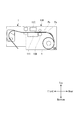
図1ないし図3に示すように、ラベル剥離装置1は、ラベルプリンター100の前方、すなわちラベルプリンター100の排紙側に装着されて使用される。そこで、まず、ラベルプリンター100について説明する。
As shown in FIGS. 1 to 3, the
ラベルプリンター100は、通信可能に接続されたコンピューター(図示省略)等から受信した画像データに基づいて、ラベル用紙Pに対してインクジェット方式により画像を記録する。なお、ラベルプリンター100は、ラベル剥離装置1を装着せずに使用することも可能である。すなわち、ラベル剥離装置1は、オプションとしてラベルプリンター100に装着される。
ラベル用紙Pは、連続紙である帯状の台紙Paと、台紙Paに略等間隔に貼付された複数のラベル部Pbとを有する。台紙Paやラベル部Pbの材質は、特に限定されるものではない。また、ラベル用紙Pは、本実施形態では、ロール紙Rとして提供されるが、これに限定されるものではなく、例えば、ファンフォールド紙であってもよい。
The
The label paper P has a strip-shaped mount Pa that is a continuous paper, and a plurality of label portions Pb attached to the mount Pa at substantially equal intervals. The material of the mount Pa and the label part Pb is not particularly limited. Further, in the present embodiment, the label paper P is provided as the roll paper R, but is not limited thereto, and may be, for example, fanfold paper.
ラベルプリンター100は、略直方体状の装置ケース101を有している。排紙側となる装置ケース101の前面には、ロール紙カバー102と、排紙テーブル103と、リリースレバー104と、電源スイッチ105と、操作パネル106と、インクカートリッジカバー107とが設けられている。また、装置ケース101の内部には、ロール紙供給部108と、記録送りローラー109と、プラテン111と、記録ヘッド112とが設けられている。
なお、記録ヘッド112は、「液体吐出部」の一例である。
The
The
ロール紙カバー102は、通常は、ロール紙供給部108の前方を覆った位置にロックされている。ユーザーは、ロール紙Rの交換時等に、リリースレバー104を操作して、ロール紙カバー102をロック解除する。これにより、ユーザーは、ロール紙カバー102を、下端部を中心として、排紙テーブル103およびリリースレバー104と共に前方に回転させ、ロール紙供給部108を開放することができる。
The
排紙テーブル103は、ラベル剥離装置1が装着されていない場合に、排出されてきたラベル用紙Pを受ける台となる。なお、ラベル剥離装置1が装着されている場合には、排出されてきたラベル用紙Pは、排紙テーブル103に受けられることなく、ラベル剥離装置1へと受け渡される。排紙テーブル103は、側面視略横台形状であり、ラベル剥離装置1のテーブル係合部17(後述する)と係合する。
The paper discharge table 103 serves as a stand for receiving the discharged label paper P when the
ロール紙供給部108には、ロール紙Rがセットされる。記録送りローラー109は、ニップローラーである。記録送りローラー109は、ラベル用紙Pを、順送り(フォアフィード)、すなわち、ロール紙供給部108から引き出し、記録ヘッド112に向けて送る。また、記録送りローラー109は、ラベル用紙Pを、逆送り(バックフィード)、すなわち、ロール紙供給部108に向けて送ることもできる。記録ヘッド112は、複数色のインク、例えばCMYKの4色に対応した複数のインクジェットヘッドを有する。記録ヘッド112は、プラテン111上に送られてきたラベル用紙Pの各ラベル部Pbに対し、インクを吐出してカラー画像を記録する。ラベル用紙Pは、記録ヘッド112を通過した後、ラベルプリンター100の前方に装着されたラベル剥離装置1に向けて送られる。
Roll paper R is set in the roll
続いて、ラベル剥離装置1について説明する。ラベル剥離装置1は、ラベルプリンター100から送られてきたラベル用紙Pの台紙Paから、ラベル部Pbを剥離する。
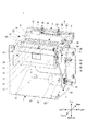
図4および図5に示すように、ラベル剥離装置1は、支持部2と、保持部3と、左ガイド軸4および右ガイド軸5と、ピールユニット6と、ユニット移動部7と、リニアエンコーダー8と、弛み検出器9と、ラベル検出器11とを備えている。
なお、ピールユニット6は、「剥離部」の一例である。ユニット移動部7は、「戻し部」の一例である。
Then, the
As shown in FIGS. 4 and 5, the
The
支持部2は、ラベル剥離装置1の各部を支持している。支持部2は、ベースプレート12と、左プレート13と、右プレートと、後プレート15と、傾斜プレート16とを備えている。
The
ベースプレート12は、略矩形板状に形成されている。左プレート13および右プレートは、ベースプレート12の左辺部および右辺部にそれぞれ固定されている。左プレート13および右プレートは、それぞれ略矩形板状に形成されている。左プレート13および右プレートの各後辺部上方寄りには、略横台形状に切り欠かれたテーブル係合部17が設けられている。テーブル係合部17は、ラベル剥離装置1がラベルプリンター100に装着される際、排紙テーブル103の幅方向(左右)両端部と係合する部位となる。右プレートには、後述する駆動プーリー53および従動プーリー54等が回転可能に支持されている。傾斜プレート16は、上面が前下がりとなるように、左プレート13および右プレートの間に設けられている。ピールユニット6によりラベル部Pbが剥離された後の台紙Paが、傾斜プレート16に受け止められ、傾斜プレート16の上面に沿って下斜め前方へと送られる。
The
保持部3は、ラベルプリンター100から送られてきたラベル用紙Pを保持する保持状態と、ラベル用紙Pを保持しない非保持状態とを取り得る。保持部3は、受け台18と、グリップ部材19と、グリップモーター21(図10参照)とを備えている。
The holding
受け台18は、左プレート13および右プレートの間を渡すようにして、左プレート13および右プレートの各上辺部後方寄りに固定されている。グリップ部材19は、受け台18上面の左右略中間部に設けられ、横長略矩形板状に形成されている。グリップ部材19は、受け台18との間でラベル用紙Pを保持する保持位置(図12(d)参照)と、ラベル用紙Pを保持しない非保持位置(図12(a)ないし(c)参照)との間で、受け台18に対して離接可能となっている。
The
グリップモーター21は、グリップ部材19を保持位置と非保持位置との間で移動させる駆動源である。なお、グリップ部材19を保持位置と非保持位置との間で移動させる駆動源としては、エアーシリンダー、ソレノイドなど、モーター以外の駆動源であってよい。ユーザーが、手動によりグリップ部材19を保持位置と非保持位置との間で移動させる構成であってもよい。
The
左ガイド軸4および右ガイド軸5は、それぞれ前後に延在しており、ピールユニット6の前後の移動をガイドする。左ガイド軸4の前端部は、固定金具22を介して左プレート13に支持され、左ガイド軸4の後端部は、受け台18を介して左プレート13に支持されている。同様に、右ガイド軸5の前端部は、固定金具22を介して右プレートに支持され、右ガイド軸5の後端部は、受け台18を介して右プレートに支持されている。
The left guide shaft 4 and the right guide shaft 5 extend in the front-rear direction and guide the front-rear movement of the
ピールユニット6は、ラベルプリンター100から送られてきたラベル用紙Pの台紙Paからラベル部Pbを剥離する。ピールユニット6は、保持部3よりも前方、つまり、ラベル用紙Pの送り経路において保持部3よりも下流側に設けられている。なお、本実施形態で「上流」「下流」とは、ラベル用紙Pの順送り方向を基準とする。ピールユニット6は、保持部3から離れた剥離開始位置(図12(a)ないし(d)参照)と、保持部3に近づいた剥離終了位置(図13(e)および(f)参照)との間を往復移動可能となっている。ピールユニット6は、保持部3によりラベル用紙Pが保持された状態で、剥離開始位置から剥離終了位置に移動することにより、台紙Paからラベル部Pbを剥離する。このため、ラベル部Pbは、ラベル用紙Pの送り経路下流側から上流側に向かって、台紙Paから剥離される。
なお、本実施形態では、剥離終了位置は固定されているが、後述するユニット移動量Cに応じて、剥離開始位置は変動するようになっている。
The
In this embodiment, the peeling end position is fixed, but the peeling start position varies according to the unit movement amount C described later.
図4ないし図7に示すように、ピールユニット6は、第1ピール部23と、第2ピール部24とを備えている。第2ピール部24は、下方に設けられたカバー軸25を中心として、第1ピール部23に対して回転可能に設けられている。すなわち、第2ピール部24は、第1ピール部23の前方を閉塞した閉塞位置(図4参照)と、第1ピール部23の前方を開放した開放位置(図6参照)との間で回転する。ユーザーは、ピールユニット6にラベル用紙Pをセットする際、第2ピール部24を閉塞位置から開放位置に回転する。続いて、ユーザーは、ラベル用紙Pの先端を、第1ピール部23の剥離駆動ローラー32(後述する)と、第2ピール部24の剥離従動ローラー48(後述する)との間に挿し入れる。そして、ユーザーは、第2ピール部24を閉塞位置に戻す。このようにして、ピールユニット6にラベル用紙Pがセットされる。ラベル部Pbが剥離された台紙Paは、第1ピール部23と第2ピール部24との間を通って、傾斜プレート16に向けて送られていく。
As shown in FIGS. 4 to 7, the
第1ピール部23は、ピールフレーム26と、ガイド装着部27と、剥離部材28と、部材支持部29と、剥離送りモーター31と、剥離駆動ローラー32とを備えている。
ピールフレーム26は、第1ピール部23の各部を支持している。ピールフレーム26は、上方および前方が開放された略箱状に形成されている。
The
The
ガイド装着部27は、ピールユニット6を、左ガイド軸4および右ガイド軸5に対して前後にスライド可能に装着するための部位となる。ガイド装着部27は、左装着部33と、右装着部34と、接続部35とを備えている。接続部35は、左右に延在して、左装着部33と右装着部34とを接続している。
The
左装着部33は、ピールフレーム26の左上端部に固定されている。左装着部33の前端部には、正面視略横「U」字状の左ガイド係合部36が設けられている。左ガイド係合部36は、左ガイド軸4に内側(右側)から係合する。
The
右装着部34は、ピールフレーム26の右上端部に固定されている。右装着部34の前後両端部には、正面視略横「U」字状の右ガイド係合部37がそれぞれ設けられている。各右ガイド係合部37は、右ガイド軸5に内側(左側)から係合する。さらに、各右ガイド係合部37の外側(右側)には、ガイドローラー38が設けられている。ガイドローラー38は、左ガイド係合部36および右ガイド係合部37が左ガイド軸4および右ガイド軸5とそれぞれ係合した状態で、ピールユニット6が前後に移動する際に、右ガイド軸5の外側(右側)に転接する。
なお、右装着部34の下面には、後述する無端ベルト56が固定されている。また、右装着部34の上面には、後述するリニア検出器59が設けられている。
The
Note that an
剥離部材28は、ピールユニット6が剥離開始位置から剥離終了位置に移動する際に、台紙Paからラベル部Pbを剥離する。剥離部材28により、ラベル用紙Pは、台紙Paのみが折り返される。剥離部材28は、接続部35の前方において、左装着部33と右装着部34との間を渡すようにして、部材支持部29の上面に設けられている。
The peeling
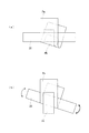
剥離部材28は、左右に細長い板状の後辺部を、下方に90°以上折り曲げた形状に形成されている。すなわち、剥離部材28は、鋭角を為す剥離エッジ39を後方に有する。この剥離エッジ39において、台紙Paが折り返される。剥離部材28の左右略中間部には、揺動軸部(図示省略)が下方に突出形成されている。揺動軸部は、部材支持部29の上面に設けられた揺動凹部(図示省略)と係合している。これにより、剥離部材28は、保持部3から剥離部材28に至る送り経路面、つまり剥離部材28の上面に略平行な面内において、揺動可能となっている。
The peeling
図8(a)に示すように、仮に剥離部材28が固定されていると、ラベル用紙Pが剥離部材28に対して斜めとなった姿勢でセットされた場合に、剥離部材28からラベル用紙Pが浮いてしまい、ラベル部Pbを剥離することができないおそれがある。これに対し、本実施形態では、図8(b)に示すように、剥離部材28が揺動可能であるため、ラベル用紙Pが剥離部材28に対して斜めとなった姿勢でセットされた場合にも、剥離部材28がラベル用紙Pの姿勢に沿うように揺動する。これにより、剥離部材28からラベル用紙Pが浮いてしまうことを抑制することができ、ラベル部Pbを適切に剥離することができる。
As shown in FIG. 8A, if the peeling
なお、剥離部材28と接続部35との間には、横中間部材41が設けられている。また、剥離部材28の左右両端部と左装着部33および右装着部34との間には、縦中間部材42がそれぞれ設けられている。剥離部材28と横中間部材41との間、および剥離部材28と縦中間部材42との間には、剥離部材28が揺動可能な程度に、間隙が設けられている。
A lateral
部材支持部29は、ピールフレーム26の左壁部と右壁部との間に設けられている。部材支持部29上面の左右略中間部には、上述したように、揺動軸部が係合する揺動凹部が設けられている。また、部材支持部29前面の左右略中間部には、検出開口43が設けられている。検出開口43からは、弛み検出器9の検出子44(後述する)が出没する。
The
剥離送りモーター31は、剥離駆動ローラー32を正逆回転させる駆動源となる。剥離送りモーター31は、ピールフレーム26の左壁部内側に固定されている。ピールフレーム26の左壁部外側には、剥離送りモーター31の駆動力を剥離駆動ローラー32に伝達する送り歯車45が設けられている。
The peeling
剥離駆動ローラー32は、第2ピール部24に設けられた剥離従動ローラー48と共に、ニップローラーである剥離送りローラー46を構成し、ラベル用紙Pを回転送りする。剥離送りローラー46は、ラベル用紙Pの送り経路において剥離部材28よりも下流側に設けられている。剥離送りローラー46は、ラベル用紙Pを、順送り(フォアフィード)および逆送り(バックフィード)することができる。剥離駆動ローラー32は、左右に延在しており、その両端部が、ピールフレーム26の左壁部および右壁部に回転可能に支持されている。
The
第2ピール部24は、ピールカバー47と、剥離従動ローラー48とを備えている。
ピールカバー47は、後面下方寄りが開放された箱状に形成されている。ピールカバー47は、カバー軸25を介して、ピールフレーム26に回転可能に取り付けられている。ピールカバー47の上面には、ラベル検出器11が設けられている。
The
The
剥離従動ローラー48は、左右に延在しており、その両端部が、ピールカバー47に回転可能に支持されている。剥離従動ローラー48は、ピールカバー47の後面下方寄りに設けられた開放部から露出しており、剥離駆動ローラー32に対して従動回転する。
The peeling driven
剥離従動ローラー48は、剥離駆動ローラー32と共に、ピールフレーム26を介して、剥離部材28と一体化されている。つまり、剥離駆動ローラー32および剥離従動ローラー48により構成される剥離送りローラー46は、剥離部材28と一体となって、剥離開始位置と剥離終了位置との間を往復移動する。したがって、保持部3に対して剥離部材28が離接した場合に、保持部3、剥離部材28および剥離送りローラー46により構成される台紙Paの折返し角度θが変わることを抑制することができる(図13(e)参照)。このため、台紙Paからラベル部Pbを安定して剥離することができる。
The peeling driven
このように構成されたピールユニット6は、剥離送りローラー46によりラベル用紙Pを順送りすることで、自らを剥離開始位置から剥離終了位置へと移動させる。すなわち、保持部3によりラベル用紙Pが保持された状態で、剥離送りローラー46によりラベル用紙Pを順送りすると、ラベル用紙Pが張った状態となる。この張った状態となったラベル用紙Pに押圧されることによって、ピールユニット6が剥離開始位置から剥離終了位置に移動する。すなわち、ラベル用紙Pに掛かったテンションにより、ピールユニット6が剥離開始位置から剥離終了位置に移動する。
The
ユニット移動部7は、ピールユニット6が剥離終了位置に移動した後、ピールユニット6を剥離開始位置に移動させるものである。ユニット移動部7は、ユニット移動モーター51と、移動歯車52と、駆動プーリー53と、2つの従動プーリー54と、テンションプーリー55と、無端ベルト56と、トルクリミッター57とを備えている。移動歯車52、駆動プーリー53、従動プーリー54、テンションプーリー55および無端ベルト56は、ユニット移動モーター51の駆動力をピールユニット6に伝達する動力伝達機構を構成している。
The unit moving part 7 moves the
ユニット移動モーター51は、ピールユニット6を剥離終了位置から剥離開始位置に移動させる駆動源となる。ユニット移動モーター51は、ベースプレート12上に固定されている。移動歯車52は、ユニット移動モーター51の出力軸に固定された出力歯車(図示省略)と噛み合っている。
The
駆動プーリー53は、歯付きのものであり、移動歯車52の右側面に同軸上で固定されている。駆動プーリー53および移動歯車52は、右プレートの下方に回転可能に支持されている。
The
2つの従動プーリー54は、右プレートの上方に回転可能に支持されている。2つの従動プーリー54は、右ガイド軸5と略平行となるように、前後に並んでいる。テンションプーリー55は、駆動プーリー53と後側の従動プーリー54との間に設けられている。テンションプーリー55は、無端ベルト56を屈曲させるようにして無端ベルト56の外周面に接しており、無端ベルト56にテンションを付与している。
The two driven
無端ベルト56は、歯付きのものであり、駆動プーリー53および2つの従動プーリー54の間に掛け渡されている。無端ベルト56には、2つの従動プーリー54の間で、上記の右装着部34が固定されている。
The
ここで、図9に示すように、駆動プーリー53が、右側面視、反時計回りに回転する方向を、第1回転方向Da1といい、時計回りに回転する方向を、第2回転方向Da2という。同様に、無端ベルト56が、右側面視、反時計回りに周回する方向を、第1周回方向Db1といい、時計回りに周回する方向を、第2周回方向Db2という。
Here, as shown in FIG. 9, the direction in which the
ユニット移動部7は、ユニット移動モーター51が駆動プーリー53を第1回転方向Da1に回転駆動することにより、無端ベルト56が第1周回方向Db1に周回し、ピールユニット6が剥離終了位置から剥離開始位置に移動する(図9(a)参照)。また、上述したように、保持部3によりラベル用紙Pが保持された状態で、剥離送りモーター31によりラベル用紙Pを順送りすると、ラベル用紙Pに押圧されることによってピールユニット6が剥離開始位置から剥離終了位置に移動する。この際、無端ベルト56が第2周回方向Db2に周回し、駆動プーリー53が第2回転方向Da2に回転する(図9(b)参照)。
In the unit moving part 7, the
トルクリミッター57は、移動歯車52の左側面に同軸上で連結されている。トルクリミッター57は、駆動プーリー53の第2回転方向Da2への回転トルクを設定トルク以下に制限する。このため、ピールユニット6が剥離開始位置から剥離終了位置に移動する際、ピールユニット6に対し、略一定の負荷が付与される。したがって、トルクリミッター57によりピールユニット6に与えられる負荷に応じたテンションが、剥離部材28で折り返されるラベル用紙Pに掛かることになる。このため、ラベル用紙Pを、剥離部材28により適切に折り返すことができる。
The
リニアエンコーダー8は、ピールユニット6の前後方向における位置を検出する。リニアエンコーダー8は、リニアスケール58と、リニア検出器59とを備えている。リニアスケール58は、右ガイド軸5と略平行となって、右ガイド軸5の上方に設けられている。つまり、リニアスケール58は、剥離開始位置と剥離終了位置との間に延在している。リニアスケール58には、スリット状の目盛り(図示省略)が設けられている。リニア検出器59は、右装着部34の上面に設けられている。リニア検出器59としては、例えばフォトインターラプターを用いることができる。リニアエンコーダー8は、ピールユニット6の移動に伴って、パルス信号をコントローラー60に出力する。
The
弛み検出器9は、剥離部材28と剥離駆動ローラー32との間のラベル用紙Pの弛みの有無を検出する。弛み検出器9としては、例えばマイクロスイッチを用いることができる。弛み検出器9の検出子44は、上記の検出開口43から出没可能となっている。
The
剥離部材28と剥離駆動ローラー32との間で、ラベル用紙Pの弛みが所定量未満になると、検出子44がラベル用紙Pに押されて検出開口43に没入し、弛み検出器9が「ON」となる。これにより、ラベル用紙Pの弛みが所定量未満になったこと、つまり弛み「無」が検出される。一方、剥離部材28と剥離駆動ローラー32との間で、ラベル用紙Pの弛みが所定量以上になると、検出子44が検出開口43から突出し、弛み検出器9が「OFF」となる。これにより、ラベル用紙Pの弛みが所定量以上になったこと、つまり弛み「有」が検出される。
When the slack of the label paper P becomes less than a predetermined amount between the peeling
ラベル検出器11は、ラベル部Pbが台紙Paから取り去られたか否かを検出する。ラベル検出器11は、ピールカバー47上面の左右略中間部に設けられている。ラベル検出器11としては、例えば反射型のフォトインターラプターを用いることができる。ラベル検出器11は、ラベル部Pbが台紙Paに残っている場合には、信号「L」を後述するコントローラー60に出力する。ラベル検出器11は、ラベル部Pbが台紙Paから取り去られた場合には、信号「H」をコントローラー60に出力する。もちろん、信号「L」と信号「H」とは逆であってもよい。
The
図10を参照して、ラベル剥離装置1の制御系について説明する。ラベル剥離装置1は、コントローラー60と、通信部70とを備えている。
通信部70は、ラベルプリンター100などの外部機器とコントローラー60との間を通信可能に接続する。通信部70は、外部機器からの各種データを受信してコントローラー60に供給する。
The control system of the
The
コントローラー60は、CPU(Central Processing Unit)および各種メモリーを備えている。コントローラー60の出力側には、グリップモーター21、剥離送りモーター31およびユニット移動モーター51が不図示のドライバーを介して接続されている。
The
コントローラー60は、機能的には、剥離量設定部61と、移動量設定部62と、移動量演算部63と、モーター制御部64とを備えている。これらの各機能部は、コントローラー60を構成するハードウェアと、メモリーに記憶されているソフトウェアとの協働によって実現される。
Functionally, the
剥離量設定部61は、剥離量Aを設定する。移動量設定部62は、剥離量設定部61により設定された剥離量Aに、所定の加算量Bを加算することにより、ユニット移動量Cを設定する。
The peel
図11を参照して、剥離量A、加算量Bおよびユニット移動量Cについて説明する。剥離量Aは、ラベル用紙Pの長さ方向において、ラベル部Pbが台紙Paから剥離される寸法に相当する。剥離量設定部61は、剥離量Aを、例えば、ラベルプリンター100から取得したラベル部Pbの長さに基づいて設定してもよく、ユーザーにより入力された値に基づいて設定してもよい。なお、剥離量Aは、ラベル部Pbの長さよりも若干短いことが好ましい。
加算量Bは、ピールユニット6が剥離開始位置に位置する際の剥離部材28と、ラベル部Pbの下流端との間の距離に相当する。つまり、剥離部材28は、加算量Bの分、ラベル部Pbの下流端よりも下流側から移動を開始する。なお、加算量Bは、0mmであってもよいが、ラベル部Pbの下流端から確実に剥離開始すべく、数ミリ程度設けることが好ましい。
ユニット移動量Cは、ピールユニット6の剥離開始位置と剥離終了位置との間の距離に相当する。
With reference to FIG. 11, the peeling amount A, the addition amount B, and the unit movement amount C will be described. The peeling amount A corresponds to a dimension at which the label portion Pb is peeled from the mount Pa in the length direction of the label paper P. The peeling
The addition amount B corresponds to the distance between the peeling
The unit movement amount C corresponds to the distance between the peeling start position and the peeling end position of the
移動量演算部63は、リニアエンコーダー8から出力されたパルス信号をカウントすることで、剥離開始位置或いは剥離終了位置に対するピールユニット6の位置、つまりピールユニット6の移動量を演算する。
モーター制御部64は、グリップモーター21、剥離送りモーター31およびユニット移動モーター51を駆動制御する。
The movement amount calculation unit 63 calculates the position of the
The
より具体的には、モーター制御部64は、ピールユニット6を剥離開始位置から剥離終了位置に移動させる際には、移動量設定部62により設定されたユニット移動量Cの分、ピールユニット6が移動するように、移動量演算部63から出力されたピールユニット6の移動量に基づいて、剥離送りモーター31を駆動制御する。これにより、設定されたユニット移動量Cに応じて、ピールユニット6を剥離開始位置から剥離終了位置へ移動させることができる。このため、剥離量設定部61が、ラベル部Pbの長さに基づいて剥離量Aを設定した場合には、ピールユニット6が、ラベル部Pbの長さに応じて、剥離開始位置から剥離終了位置に移動する。したがって、ラベル部Pbの長さに応じた量を剥離することができる。
More specifically, when the
また、モーター制御部64は、ピールユニット6を剥離終了位置から剥離開始位置に移動させる際には、移動量設定部62により設定されたユニット移動量Cの分、ピールユニット6が移動するように、移動量演算部63から出力されたピールユニット6の移動量に基づいて、ユニット移動モーター51を駆動制御する。これにより、設定されたユニット移動量Cに応じて、ピールユニット6を剥離終了位置から剥離開始位置へ移動させることができる。このため、剥離量設定部61が、ラベル部Pbの長さに基づいて剥離量Aを設定した場合には、ピールユニット6が、ラベル部Pbの長さに応じて、剥離終了位置から剥離開始位置に移動する。例えば、ラベル部Pbの長さが長い場合には、その分、剥離開始位置が前方に位置することになる。
なお、剥離開始位置を固定し、ユニット移動量Cに応じて、剥離終了位置が変動する構成であってもよく、ユニット移動量Cに応じて、剥離開始位置および剥離終了位置の両者が変動する構成であってもよい。
Further, when the
The peeling start position may be fixed, and the peeling end position may vary according to the unit movement amount C. Both the peeling start position and the peeling end position vary depending on the unit movement amount C. It may be a configuration.
また、モーター制御部64は、剥離送りローラー46によりラベル用紙Pを順送りした後、つまりピールユニット6が剥離開始位置から剥離終了位置に移動した後、ラベル検出器11から信号「L」が出力されている場合、つまりラベル部Pbが台紙Paから取り去られていない場合には、ユニット移動モーター51の駆動を禁止する。これにより、台紙Paから剥離されたラベル部Pbが、再び台紙Paに貼り付いてしまうことを抑制することができる。モーター制御部64は、ラベル検出器11から信号「H」が出力されている場合、つまりラベル部Pbが台紙Paから取り去られた場合には、ユニット移動モーター51の駆動を許可する。
さらに、詳細は後述するが、モーター制御部64は、弛み検出器9の検出結果に基づいて、剥離送りモーター31を制御する。
The
Furthermore, although details will be described later, the
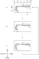
図12および図13を参照して、ラベルプリンター100においてラベル部Pbに画像を記録した後、ラベル剥離装置1において、台紙Paからラベル部Pbを剥離する際の一連の動作について説明する。
With reference to FIG. 12 and FIG. 13, a series of operations when the
図12(a)は、記録対象となるラベル部Pbが、記録ヘッド112に対して頭出しされた状態を示している。このとき、ラベル剥離装置1の保持部3は、非保持状態にある。また、ピールユニット6は、剥離開始位置に位置している。この状態から、図12(b)に示すように、ラベルプリンター100は、記録送りローラー109によりラベル用紙Pを順送りしつつ、記録ヘッド112からインクを吐出して、ラベル部Pbに画像を記録する。この際、ラベル剥離装置1は、剥離送りローラー46により、ラベル用紙Pを弛ませた状態で順送りする。
FIG. 12A shows a state in which the label portion Pb to be recorded is cued with respect to the
続いて、図12(c)に示すように、記録送りローラー109および剥離送りローラー46により、画像が記録されたラベル部Pbがピール位置までくるように、ラベル用紙Pを弛ませた状態で順送りする。ここで、ピール位置は、ラベル部Pbの下流端が、剥離部材28よりも加算量Bの分、下流側にくる位置に相当する。このように、ラベルプリンター100からラベル用紙Pが送られてくる際に、剥離送りローラー46によりラベル用紙Pを送ることで、ラベル用紙Pが過度に弛んだ状態となることを抑制することができる。
Subsequently, as shown in FIG. 12C, the recording
続いて、図12(d)に示すように、保持部3を保持状態とし、保持部3によりラベル用紙Pを保持する。続いて、図13(e)に示すように、保持部3によりラベル用紙Pを保持したまま、剥離送りローラー46により、ユニット移動量Cに相当する分、ラベル用紙Pを張った状態で順送りする。これにより、ピールユニット6が剥離開始位置から剥離終了位置に移動する。その結果、ラベル部Pbが、剥離量Aの分、下流端から剥離される。なお、ピールユニット6が剥離終了位置に移動した状態で、ラベル部Pbの上流側端部は、台紙Paに付着したままとなっている。
Subsequently, as shown in FIG. 12D, the holding
続いて、図13(f)に示すように、ユーザーにより、ラベル部Pbが台紙Paから取り去られる。このようにして、ユーザーは、ラベル部Pbに所望の印刷がなされたラベルを得ることができる。ラベル部Pbが台紙Paから取り去られると、ラベル検出器11が信号「H」をコントローラー60に出力する。これにより、モーター制御部64は、ユニット移動モーター51の駆動を許可する。
Subsequently, as shown in FIG. 13F, the label part Pb is removed from the mount Pa by the user. In this way, the user can obtain a label on which desired printing has been performed on the label portion Pb. When the label portion Pb is removed from the mount Pa, the
続いて、図13(g)に示すように、剥離送りローラー46により、ラベル用紙Pを逆送りしつつ、ユニット移動部7により、ユニット移動量Cの分、ピールユニット6を剥離終了位置から剥離開始位置に移動させる。このとき、ラベル用紙Pの送り量は、ピールユニット6が剥離開始位置に戻った際にも、ラベル用紙Pの弛みが確保できる量とする。このように、ピールユニット6が剥離終了位置から剥離開始位置に移動するのと同時に、剥離送りローラー46がラベル用紙Pを逆送りすることで、ピールユニット6が剥離終了位置から剥離開始位置に移動する際に、保持部3によりラベル用紙Pを保持した状態でも、ピールユニット6がラベル用紙Pに邪魔されることなく、スムースに移動することができる。なお、ラベル用紙Pの逆送りと、ピールユニット6の剥離終了位置から剥離開始位置への移動とを、同時に行う必要はなく、ラベル用紙Pの逆送りを行った後、ピールユニット6の移動を行うようにしてもよい。
Subsequently, as shown in FIG. 13 (g), the peel
続いて、図13(h)に示すように、グリップモーター21を駆動して、グリップ部材19を非保持位置まで移動させることにより、保持部3を非保持状態とする。続いて、記録送りローラー109および剥離送りローラー46により、次のラベル部Pbが記録開始位置までくるように、ラベル用紙Pを弛ませた状態で逆送りする。これにより、一連の動作を終了する。
Subsequently, as shown in FIG. 13H, the
上述したように、ラベル剥離装置1では、保持部3が非保持状態にある場合にラベル用紙Pを送るときには、ラベル用紙Pを弛ませた状態で送るようにしている。これにより、記録送りローラー109の回転送り量、つまり記録送りローラー109の外周長に記録送りローラー109の回転数を掛けた値、に対して、ラベル用紙Pの実際の送り量に誤差が生じてしまうことを抑制している。以下、その仕組みについて説明する。
As described above, in the
次に、ラベル用紙Pを順送りする場合について説明する。
図14(a)に示すように、弛み検出器9が「OFF」の状態から、記録送りローラー109の回転送り速度Vpfに比べ、剥離送りローラー46の回転送り速度Vpeが大きくなるようにして、ラベル用紙Pを順送りする。このため、記録送りローラー109と剥離送りローラー46との間で、ラベル用紙Pの弛みが小さくなっていく。なお、記録送りローラー109の回転送り速度Vpfとは、記録送りローラー109の外周長に記録送りローラー109の回転速度を掛けた値である。剥離送りローラー46の回転送り速度Vpeとは、剥離送りローラー46の外周長に剥離送りローラー46の回転速度を掛けた値である。
Next, a case where the label sheets P are sequentially fed will be described.
As shown in FIG. 14A, from the state in which the
図14(b)に示すように、ラベル用紙Pの弛みが所定量未満になると、弛み検出器9が「ON」になり、弛み「無」が検出される。弛み検出器9が「ON」になると、モーター制御部64は、剥離送りローラー46を停止する。これにより、剥離送りローラー46がラベル用紙Pの順送りを停止する。このとき、記録送りローラー109は、回転したままである。そのため、ラベル用紙Pの弛みは大きくなっていく。図14(c)に示すように、ラベル用紙Pの弛みが所定量以上になると、弛み検出器9が「OFF」になり、弛み「有」が検出される。図14(a)に示すように、弛み検出器9が「OFF」になると、モーター制御部64は、ディレイを掛けて、つまり所定時間後に剥離送りローラー46を再び駆動する。これにより、剥離送りローラー46がラベル用紙Pの順送りを再開する。この一連の処理を繰り返すことで、常に一定以上の弛みを確保することができる。したがって、順送り時に、記録送りローラー109の回転送り量に比べ、ラベル用紙Pの実際の送り量が多くなることが抑制される。
As shown in FIG. 14B, when the slack of the label paper P becomes less than a predetermined amount, the
次に、ラベル用紙Pを逆送りする場合について説明する。
図15(a)に示すように、弛み検出器9が「ON」の状態から、記録送りローラー109の回転送り速度Vpfに比べ、剥離送りローラー46の回転送り速度Vpeが大きくなるようにして、ラベル用紙Pを逆送りする。このため、記録送りローラー109と剥離送りローラー46との間で、ラベル用紙Pの弛みが大きくなっていく。図15(b)に示すように、ラベル用紙Pの弛みが所定量以上になると、弛み検出器9が「OFF」になり、弛み「有」が検出される。図15(c)に示すように、弛み検出器9が「OFF」になると、モーター制御部64は、ディレイを掛けて、つまり所定時間後に剥離送りローラー46を停止する。これにより、剥離送りローラー46がラベル用紙Pの逆送りを停止する。このとき、記録送りローラー109は、回転したままである。そのため、ラベル用紙Pの弛みは小さくなっていく。図15(a)に示すように、ラベル用紙Pの弛みが所定量未満になると、弛み検出器9が「ON」になり、弛み「無」が検出される。弛み検出器9が「ON」になると、モーター制御部64は、剥離送りローラー46を再び駆動する。これにより、剥離送りローラー46がラベル用紙Pの逆送りを再開する。この一連の処理を繰り返すことで、常に一定以上の弛みを確保することができる。したがって、逆送り時に、記録送りローラー109の回転送り量に比べ、ラベル用紙Pの実際の送り量が少なくなることが抑制される。
Next, the case where the label paper P is fed backward will be described.
As shown in FIG. 15A, from the state in which the
以上のように、本実施形態のラベル剥離装置1によれば、ラベル用紙Pに押圧されることによってピールユニット6が剥離開始位置から剥離終了位置に移動することで、ピールユニット6は、剥離送りローラー46によるラベル用紙Pの送り速度に応じて移動する。したがって、剥離部材28がラベル用紙Pから離れることが抑制され、ラベル用紙Pが弛んでしまうことが抑制される。このため、ラベル用紙Pが剥離部材28で折り返された状態を確保することができる。ゆえに、台紙Paからラベル部Pbを適切に剥離することができる。
As described above, according to the
なお、本実施形態は、以下のような形態に変更することができる。
ピールユニット6において、剥離送りローラー46は移動せず、剥離部材28のみが剥離開始位置と剥離終了位置との間で移動する構成であってもよい。
In addition, this embodiment can be changed into the following forms.
In the
ラベル剥離装置1をラベルプリンター100と一体化した構成であってもよい。すなわち、ラベルプリンター100が、保持部3およびピールユニット6など、ラベル剥離装置1の各部を備えた構成であってもよい。
液体吐出装置としては、インクを吐出するものに限らず、コーティング剤など、各種液体を吐出するものであってもよい。
The
The liquid ejecting apparatus is not limited to an apparatus that ejects ink but may be an apparatus that ejects various liquids such as a coating agent.
1:ラベル剥離装置
3:保持部
6:ピールユニット
28:剥離部材
46:剥離送りローラー
100:ラベルプリンター
P:ラベル用紙
Pa:台紙
Pb:ラベル部
1: Label peeling device 3: Holding part 6: Peel unit 28: Peeling member 46: Peeling feed roller 100: Label printer P: Label paper Pa: Mount Pb: Label part
Claims (4)
前記ラベル用紙が前記液体吐出装置から前記保持部に向かう方向に送られる送り経路において前記保持部よりも下流側に設けられ、前記台紙から前記ラベル部を剥離する剥離部と、を備え、
前記剥離部は、
第1位置と、前記第1位置より前記保持部に近い第2位置との間で移動可能であり、前記台紙を折り返す剥離部材と、
前記送り経路において前記剥離部材よりも下流側に設けられ、前記ラベル用紙を送る送り部と、を有し、
前記剥離部材は、前記保持部により保持された状態で前記送り部により送られる前記ラベル用紙により押圧されることで、前記第1位置から前記第2位置に向かう方向に移動し、
前記剥離部材の前記第1位置から前記第2位置に向かう方向への移動に対して負荷を与える負荷付与部と、
前記剥離部材を前記第2位置から前記第1位置に向かう方向へ移動させる駆動源と、
プーリーを含み、前記駆動源の駆動力を前記剥離部材に伝達する動力伝達機構と、を備え、
前記駆動源が前記プーリーを第1回転方向に回転駆動することにより、前記剥離部材が前記第2位置から前記第1位置に向かう方向に移動し、
前記プーリーは、前記剥離部材が前記第1位置から前記第2位置に向かう方向に移動する際に、前記第1回転方向とは逆の第2回転方向に回転し、
前記負荷付与部は、前記プーリーに連結され、前記プーリーの前記第2回転方向への回転トルクを制限するトルクリミッター、を有する、ラベル剥離装置。 A holding state for holding the label sheet sent from a liquid discharge device that discharges liquid to a label sheet having a label part and a mount on which the label part is attached, and the label sheet is movable. A non-holding state that does not hold the label paper;
A separation unit that is provided on the downstream side of the holding unit in a feeding path in which the label paper is sent in a direction from the liquid ejection device toward the holding unit, and that peels off the label unit from the mount.
The peeling portion is
A peeling member that is movable between a first position and a second position that is closer to the holding unit than the first position;
A feed section that is provided downstream of the peeling member in the feed path and feeds the label paper;
The peeling member moves in a direction from the first position toward the second position by being pressed by the label paper fed by the feeding unit while being held by the holding unit ,
A load applying unit that applies a load to the movement of the peeling member from the first position toward the second position;
A drive source for moving the peeling member in a direction from the second position toward the first position;
A power transmission mechanism including a pulley and transmitting a driving force of the driving source to the peeling member;
When the drive source rotates the pulley in the first rotation direction, the peeling member moves from the second position toward the first position,
The pulley rotates in a second rotation direction opposite to the first rotation direction when the peeling member moves in a direction from the first position toward the second position,
The load applying unit includes a torque limiter that is coupled to the pulley and limits a rotational torque of the pulley in the second rotation direction .
前記液体吐出部により液体が吐出された前記ラベル用紙を保持する保持状態と、前記ラベル用紙が移動可能である前記ラベル用紙を保持しない非保持状態と、になり得る保持部と、
前記ラベル用紙が前記液体吐出部から前記保持部に向かう方向に送られる送り経路において前記保持部よりも下流側に設けられ、前記台紙から前記ラベル部を剥離する剥離部と、を備え、
前記剥離部は、
第1位置と、前記第1位置より前記保持部に近い第2位置との間で移動可能であり、前記台紙を折り返す剥離部材と、
前記送り経路において前記剥離部材よりも下流側に設けられ、前記ラベル用紙を送る送り部と、を有し、
前記剥離部材は、前記保持部により保持された状態で前記送り部により送られる前記ラベル用紙により押圧されることで、前記第1位置から前記第2位置に向かう方向に移動し、
前記剥離部材の前記第1位置から前記第2位置に向かう方向への移動に対して負荷を与える負荷付与部と、
前記剥離部材を前記第2位置から前記第1位置に向かう方向へ移動させる駆動源と、
プーリーを含み、前記駆動源の駆動力を前記剥離部材に伝達する動力伝達機構と、を備え、
前記駆動源が前記プーリーを第1回転方向に回転駆動することにより、前記剥離部材が前記第2位置から前記第1位置に向かう方向に移動し、
前記プーリーは、前記剥離部材が前記第1位置から前記第2位置に向かう方向に移動する際に、前記第1回転方向とは逆の第2回転方向に回転し、
前記負荷付与部は、前記プーリーに連結され、前記プーリーの前記第2回転方向への回転トルクを制限するトルクリミッター、を有する、液体吐出装置。 A liquid ejecting unit that ejects liquid to a label sheet having a label unit and a mount to which the label unit is attached;
A holding unit that can be in a holding state that holds the label paper from which liquid has been discharged by the liquid discharge unit, and a non-holding state in which the label paper is movable and does not hold the label paper;
A separation unit that is provided on the downstream side of the holding unit in a feeding path in which the label sheet is sent in a direction from the liquid discharge unit toward the holding unit, and that peels off the label unit from the mount.
The peeling portion is
A peeling member that is movable between a first position and a second position that is closer to the holding unit than the first position;
A feed section that is provided downstream of the peeling member in the feed path and feeds the label paper;
The peeling member moves in a direction from the first position toward the second position by being pressed by the label paper fed by the feeding unit while being held by the holding unit ,
A load applying unit that applies a load to the movement of the peeling member from the first position toward the second position;
A drive source for moving the peeling member in a direction from the second position toward the first position;
A power transmission mechanism including a pulley and transmitting a driving force of the driving source to the peeling member;
When the drive source rotates the pulley in the first rotation direction, the peeling member moves from the second position toward the first position,
The pulley rotates in a second rotation direction opposite to the first rotation direction when the peeling member moves in a direction from the first position toward the second position,
The load applying unit includes a torque limiter that is coupled to the pulley and limits a rotational torque of the pulley in the second rotation direction .
前記保持部により保持された状態で、前記ラベル用紙が前記液体吐出装置から前記保持部に向かう方向に送られる送り経路において前記保持部よりも下流側に設けられ、台紙を折り返す剥離部材より、前記送り経路において下流側に設けられる送り部により前記台紙を送り、
前記剥離部材が、前記保持部により保持された状態で前記送り部により送られる前記前記台紙により、第1位置から、前記第1位置より前記保持部に近い第2位置に向かう方向に押圧され、前記剥離部材の前記第1位置から前記第2位置に向かう方向の移動により、前記台紙からラベル部が剥離され、
駆動源がプーリーを第1回転方向に回転駆動することにより、前記剥離部材が前記第2位置から前記第1位置に向かう方向に移動し、
前記プーリーは、前記剥離部材が前記第1位置から前記第2位置に向かう方向に移動する際に、前記第1回転方向とは逆の第2回転方向に回転し、
前記プーリーに連結されたトルクリミッターが、前記プーリーの前記第2回転方向への回転トルクを制限することにより、前記剥離部材の前記第1位置から前記第2位置に向かう方向への移動に対して負荷を与える、ラベル剥離方法。 Liquid is discharged by the liquid discharge device, and the label paper sent from the liquid discharge device is held by the holding unit,
In a state of being held by the holding unit, the label paper is provided on the downstream side of the holding unit in a feeding path in which the label paper is sent in the direction from the liquid ejection device to the holding unit, and more than the peeling member that folds the mount, The mount is fed by a feed unit provided on the downstream side in the feed path,
The peeling member is pressed in a direction from the first position toward the second position closer to the holding unit than the first position by the mount sent by the feeding unit while being held by the holding unit, Due to the movement of the peeling member in the direction from the first position to the second position, the label portion is peeled from the mount ,
When the driving source rotationally drives the pulley in the first rotation direction, the peeling member moves from the second position toward the first position,
The pulley rotates in a second rotation direction opposite to the first rotation direction when the peeling member moves in a direction from the first position toward the second position,
A torque limiter connected to the pulley limits the rotational torque of the pulley in the second rotational direction, thereby preventing the peeling member from moving from the first position toward the second position. Label peeling method that gives load .
前記ラベル用紙が前記液体吐出装置から前記保持部に向かう方向に送られる送り経路において前記保持部よりも下流側に設けられ、前記台紙から前記ラベル部を剥離する剥離部と、を備え、
前記剥離部は、
第1位置と、前記第1位置より前記保持部に近い第2位置との間で移動可能であり、前記台紙を折り返す剥離部材と、
前記送り経路において前記剥離部材よりも下流側に設けられ、前記ラベル用紙を送る送り部と、を有し、
前記剥離部材は、前記保持部により保持された状態で前記送り部により送られる前記ラベル用紙により押圧されることで、前記第1位置から前記第2位置に向かう方向に移動し、
前記剥離部材には、揺動軸部が設けられており、
前記剥離部材は、前記保持部から前記剥離部材に至る送り経路面に略平行な面内において、前記ラベル用紙により前記揺動軸部を中心として揺動可能に設けられている、ラベル剥離装置。 A holding state for holding the label sheet sent from a liquid discharge device that discharges liquid to a label sheet having a label part and a mount on which the label part is attached, and the label sheet is movable. A non-holding state that does not hold the label paper;
A separation unit that is provided on the downstream side of the holding unit in a feeding path in which the label paper is sent in a direction from the liquid ejection device toward the holding unit, and that peels off the label unit from the mount.
The peeling portion is
A peeling member that is movable between a first position and a second position that is closer to the holding unit than the first position;
A feed section that is provided downstream of the peeling member in the feed path and feeds the label paper;
The peeling member moves in a direction from the first position toward the second position by being pressed by the label paper fed by the feeding unit while being held by the holding unit ,
The peeling member is provided with a swing shaft portion,
The label peeling device, wherein the peeling member is provided so as to be swingable about the swinging shaft portion by the label paper in a plane substantially parallel to a feed path surface from the holding portion to the peeling member .
Priority Applications (5)
| Application Number | Priority Date | Filing Date | Title |
|---|---|---|---|
| JP2014125894A JP6417744B2 (en) | 2014-06-19 | 2014-06-19 | Label peeling device, liquid ejection device, and label peeling method |
| CN201510303204.7A CN105313486B (en) | 2014-06-19 | 2015-06-04 | Label stripping apparatus, liquid discharge device and label stripping means |
| KR1020150085724A KR101785782B1 (en) | 2014-06-19 | 2015-06-17 | Label peeling device, fluid ejection device, and label peeling method |
| EP15172695.7A EP2957513B1 (en) | 2014-06-19 | 2015-06-18 | Label peeling device, fluid ejection device, and label peeling method |
| US14/744,679 US10086598B2 (en) | 2014-06-19 | 2015-06-19 | Label peeling device, fluid ejection device, and label peeling method |
Applications Claiming Priority (1)
| Application Number | Priority Date | Filing Date | Title |
|---|---|---|---|
| JP2014125894A JP6417744B2 (en) | 2014-06-19 | 2014-06-19 | Label peeling device, liquid ejection device, and label peeling method |
Publications (3)
| Publication Number | Publication Date |
|---|---|
| JP2016003047A JP2016003047A (en) | 2016-01-12 |
| JP2016003047A5 JP2016003047A5 (en) | 2017-07-20 |
| JP6417744B2 true JP6417744B2 (en) | 2018-11-07 |
Family
ID=53539473
Family Applications (1)
| Application Number | Title | Priority Date | Filing Date |
|---|---|---|---|
| JP2014125894A Expired - Fee Related JP6417744B2 (en) | 2014-06-19 | 2014-06-19 | Label peeling device, liquid ejection device, and label peeling method |
Country Status (5)
| Country | Link |
|---|---|
| US (1) | US10086598B2 (en) |
| EP (1) | EP2957513B1 (en) |
| JP (1) | JP6417744B2 (en) |
| KR (1) | KR101785782B1 (en) |
| CN (1) | CN105313486B (en) |
Families Citing this family (15)
| Publication number | Priority date | Publication date | Assignee | Title |
|---|---|---|---|---|
| JP2016169085A (en) * | 2015-03-13 | 2016-09-23 | 株式会社沖データ | Label medium conveyance device, printer, and label medium conveyance method |
| CN106742459A (en) * | 2016-11-19 | 2017-05-31 | 无锡中环包装有限公司 | Squeeze and push away stripping type packaging label peel plate |
| CN106628465A (en) * | 2016-11-19 | 2017-05-10 | 无锡中环包装有限公司 | Package label peeling plate structure |
| CN106395045A (en) * | 2016-11-19 | 2017-02-15 | 无锡中环包装有限公司 | Rolling type stripping assembly for packing label |
| CN106516320A (en) * | 2016-11-19 | 2017-03-22 | 无锡中环包装有限公司 | Swinging extruding pulling type packaging label stripping plate |
| CN106742458A (en) * | 2016-11-19 | 2017-05-31 | 无锡中环包装有限公司 | Adhesive label peel plate |
| US10543948B2 (en) | 2017-04-05 | 2020-01-28 | Boston Scientific Scimed, Inc. | Fixture for use with a medical device label printing system |
| WO2019113140A1 (en) * | 2017-12-06 | 2019-06-13 | Robert Almblad | Food dispensing module for a delaminating food dispensing system |
| CN108248194A (en) * | 2017-12-27 | 2018-07-06 | 深圳盟星科技股份有限公司 | Winder device |
| CN110641795A (en) * | 2018-06-26 | 2020-01-03 | 捷普电子(新加坡)公司 | Label stripping machine and stripping device thereof |
| JP7120954B2 (en) * | 2019-03-26 | 2022-08-17 | 東芝テック株式会社 | label printer and program |
| JP2021014022A (en) * | 2019-07-10 | 2021-02-12 | セイコーエプソン株式会社 | Label printer |
| JP7326949B2 (en) * | 2019-07-11 | 2023-08-16 | セイコーエプソン株式会社 | Label printer |
| JP7326950B2 (en) * | 2019-07-11 | 2023-08-16 | セイコーエプソン株式会社 | Printing device and printing method |
| CN111703673A (en) * | 2020-06-19 | 2020-09-25 | 汪汇川 | Small automatic label tearing machine for processing multiple pieces of label paper |
Family Cites Families (18)
| Publication number | Priority date | Publication date | Assignee | Title |
|---|---|---|---|---|
| SE425841B (en) * | 1977-07-19 | 1982-11-15 | Rune Torsten Qwarfort | LABELING MACHINE |
| JPS55128159U (en) * | 1979-03-01 | 1980-09-10 | ||
| DE3233546A1 (en) * | 1982-09-10 | 1984-03-15 | Hermann Gmbh Co Heinrich | Labelling device |
| US4581094A (en) * | 1983-01-25 | 1986-04-08 | Kabushiki Kaisha Ishida Koki Seisakusho | Device for suction-sticking display labels |
| DE3618542A1 (en) * | 1986-06-03 | 1987-12-10 | Hermann Gmbh Co Heinrich | METHOD AND DEVICE FOR DONATING LABELS STICKING ON A CARRIER TAPE |
| JPH10203518A (en) | 1997-01-17 | 1998-08-04 | Hitachi Ltd | Label detaching apparatus |
| US5938890A (en) * | 1998-06-27 | 1999-08-17 | Automatic Manufacturing Systems, Inc. | Adhesive components peel and apply apparatus and method |
| JP2001163517A (en) * | 1999-12-15 | 2001-06-19 | Tokyo Ueruzu:Kk | Label separator |
| US6758254B2 (en) * | 2001-10-16 | 2004-07-06 | Nautilus Systems, Inc. | Method and apparatus for removing and applying adhesive components |
| US6766844B1 (en) * | 2001-10-30 | 2004-07-27 | Zih Corp. | Peel assembly for a printer |
| JP4098048B2 (en) * | 2002-09-25 | 2008-06-11 | セイコーインスツル株式会社 | Label peeling mechanism for label continuum and label printer using the mechanism |
| JP2006076587A (en) * | 2004-09-07 | 2006-03-23 | Sato Corp | Label releasing apparatus |
| JP2007008488A (en) | 2005-06-28 | 2007-01-18 | Toshiba Matsushita Display Technology Co Ltd | Label peeling apparatus, label peeling method, and manufacturing method for plane displaying device |
| JP2009012851A (en) * | 2007-07-09 | 2009-01-22 | Hitachi Metals Ltd | Label peeling method and label peeling apparatus |
| JP5039805B2 (en) * | 2010-03-05 | 2012-10-03 | 株式会社沖データ | Label printer |
| JP5781758B2 (en) * | 2010-12-27 | 2015-09-24 | 日本電産サンキョー株式会社 | Labeling device |
| JP5774365B2 (en) | 2011-05-12 | 2015-09-09 | 株式会社ブリヂストン | Label peeling device |
| JP6055256B2 (en) * | 2012-09-28 | 2016-12-27 | キヤノンファインテック株式会社 | Recording apparatus and recording system |
-
2014
- 2014-06-19 JP JP2014125894A patent/JP6417744B2/en not_active Expired - Fee Related
-
2015
- 2015-06-04 CN CN201510303204.7A patent/CN105313486B/en not_active Expired - Fee Related
- 2015-06-17 KR KR1020150085724A patent/KR101785782B1/en active IP Right Grant
- 2015-06-18 EP EP15172695.7A patent/EP2957513B1/en not_active Not-in-force
- 2015-06-19 US US14/744,679 patent/US10086598B2/en not_active Expired - Fee Related
Also Published As
| Publication number | Publication date |
|---|---|
| US20150367624A1 (en) | 2015-12-24 |
| US10086598B2 (en) | 2018-10-02 |
| CN105313486A (en) | 2016-02-10 |
| JP2016003047A (en) | 2016-01-12 |
| KR101785782B1 (en) | 2017-10-16 |
| EP2957513B1 (en) | 2018-04-18 |
| CN105313486B (en) | 2019-04-16 |
| EP2957513A1 (en) | 2015-12-23 |
| KR20150146414A (en) | 2015-12-31 |
Similar Documents
| Publication | Publication Date | Title |
|---|---|---|
| JP6417744B2 (en) | Label peeling device, liquid ejection device, and label peeling method | |
| JP5130853B2 (en) | Image recording device | |
| JP2016005961A (en) | Label peel device, ink jet recording device and label peel method | |
| US9937699B2 (en) | Label peeling device, fluid ejection device, and label peeling method | |
| JP6111615B2 (en) | Image forming apparatus | |
| WO2014010736A1 (en) | Medium-machining device and medium-machining method | |
| JP4155010B2 (en) | Recording device | |
| JP6417743B2 (en) | Label peeling device, liquid ejection device, and label peeling method | |
| US11897258B2 (en) | Printing apparatus | |
| JP7472518B2 (en) | Printing device | |
| JP4957004B2 (en) | Inkjet recording device | |
| JP7310390B2 (en) | Cutter device and printing device | |
| JP2022041210A (en) | Printer | |
| US20080080920A1 (en) | Printer and method of controlling printer | |
| JP5966545B2 (en) | Medium loading apparatus and recording apparatus | |
| JP5166807B2 (en) | Image recording device with cutter | |
| JP7456346B2 (en) | printing device | |
| JP7439715B2 (en) | Device | |
| JP7338377B2 (en) | Paper feed unit | |
| JP2018020494A (en) | Printer | |
| JP6356917B2 (en) | Inkjet printer | |
| JP2009131997A (en) | Waiting method of image recorder and continuous medium | |
| JP2009090498A (en) | Image recording device | |
| JP2021104634A (en) | Printer and conveyance control method | |
| JP2009149032A (en) | Recording device |
Legal Events
| Date | Code | Title | Description |
|---|---|---|---|
| A521 | Request for written amendment filed |
Free format text: JAPANESE INTERMEDIATE CODE: A523 Effective date: 20170609 |
|
| A621 | Written request for application examination |
Free format text: JAPANESE INTERMEDIATE CODE: A621 Effective date: 20170609 |
|
| A977 | Report on retrieval |
Free format text: JAPANESE INTERMEDIATE CODE: A971007 Effective date: 20180316 |
|
| A131 | Notification of reasons for refusal |
Free format text: JAPANESE INTERMEDIATE CODE: A131 Effective date: 20180410 |
|
| A521 | Request for written amendment filed |
Free format text: JAPANESE INTERMEDIATE CODE: A523 Effective date: 20180607 |
|
| TRDD | Decision of grant or rejection written | ||
| A01 | Written decision to grant a patent or to grant a registration (utility model) |
Free format text: JAPANESE INTERMEDIATE CODE: A01 Effective date: 20180911 |
|
| A61 | First payment of annual fees (during grant procedure) |
Free format text: JAPANESE INTERMEDIATE CODE: A61 Effective date: 20180924 |
|
| R150 | Certificate of patent or registration of utility model |
Ref document number: 6417744 Country of ref document: JP Free format text: JAPANESE INTERMEDIATE CODE: R150 |
|
| LAPS | Cancellation because of no payment of annual fees |