JP6382391B1 - Elevator counterweight frame reinforcement support device and elevator balance weight frame reinforcement mounting method - Google Patents
Elevator counterweight frame reinforcement support device and elevator balance weight frame reinforcement mounting method Download PDFInfo
- Publication number
- JP6382391B1 JP6382391B1 JP2017086886A JP2017086886A JP6382391B1 JP 6382391 B1 JP6382391 B1 JP 6382391B1 JP 2017086886 A JP2017086886 A JP 2017086886A JP 2017086886 A JP2017086886 A JP 2017086886A JP 6382391 B1 JP6382391 B1 JP 6382391B1
- Authority
- JP
- Japan
- Prior art keywords
- weight
- weights
- frame
- counterweight
- elevator
- Prior art date
- Legal status (The legal status is an assumption and is not a legal conclusion. Google has not performed a legal analysis and makes no representation as to the accuracy of the status listed.)
- Active
Links
Images


Classifications
-
- B—PERFORMING OPERATIONS; TRANSPORTING
- B66—HOISTING; LIFTING; HAULING
- B66B—ELEVATORS; ESCALATORS OR MOVING WALKWAYS
- B66B17/00—Hoistway equipment
- B66B17/12—Counterpoises
Abstract
【課題】エレベーター釣合おもり枠の補強材取付において、作業しやすい場所で作業が可能で、労力と作業時間を少なくすることである。
【解決手段】2つの縦枠、上枠、及び下枠を組み合わせて形成された釣合おもり枠24に積み重ねた所定数のおもりを収容したエレベーターの釣合おもり22において、おもりの積み重ねの中間に補強材を取付ける作業を支援する取付支援装置50は、積み重ねられた2つのおもりについて上方側のおもりの縁部の丸みと下方側のおもりの縁部の丸みとによって形成された積み重ね谷部に入り込むことができ上方側のおもりの下面を支持可能な形状を有するおもり保持工具70と、釣合おもり枠24に取付け可能な揚重部52と、おもり保持工具70と揚重部52とを接続する揚重接続部と、を含む。
【選択図】図2An object of the present invention is to provide an elevator balancing weight frame with a reinforcing member, which can be operated in a place where it is easy to work, and can reduce labor and working time.
In a counterweight 22 of an elevator that accommodates a predetermined number of weights stacked on a counterweight frame 24 formed by combining two vertical frames, an upper frame, and a lower frame, in the middle of the stacking of the weights. The attachment support device 50 that supports the work of attaching the reinforcing material enters the stacked valley portion formed by the roundness of the edge of the upper weight and the roundness of the edge of the lower weight of the two stacked weights. The weight holding tool 70 having a shape capable of supporting the lower surface of the upper weight, the lifting portion 52 attachable to the counterweight frame 24, and the weight holding tool 70 and the lifting portion 52 are connected to each other. A lifting connection.
[Selection] Figure 2
Description
本開示は、エレベーター釣合おもり枠の補強材取付支援装置及びエレベーター釣合おもり枠の補強材取付方法に関する。 The present disclosure relates to a reinforcing material attachment support device for an elevator balancing weight frame and a reinforcing material attachment method for an elevator balancing weight frame.
特許文献1には、エレベーターの釣合おもりを昇降路から乗場に搬出する装置において、釣合おもり用の一対のガイドレールに固定横板を取付け、その固定横板と釣合おもり枠との間にチェーンブロックとフックとワイヤとを含む支持装置を用いることが開示されている。
In
特許文献2には、エレベーター釣合おもり枠の一対の縦枠の間が広がることを規制するために、一対の縦枠のそれぞれにおもり押え用の固定具を固定し、2つの固定具の間をターンバックルと枠幅調整ボルトで接続することが開示されている。 In Patent Document 2, in order to restrict the spread between the pair of vertical frames of the elevator balance weight frame, a weight holding fixture is fixed to each of the pair of vertical frames, and a space between the two fixtures is fixed. Is connected to the turnbuckle with a frame width adjusting bolt.
エレベーター釣合おもり枠の一対の縦枠の間が広がることを防ぐために、おもりの積み重ねの中間に補強材を配置し、これを1対の縦枠にそれぞれに固定することが行われる。既設のエレベーターにおいてこの補強材の取付作業を行うには、釣合おもり枠に既に積み重ねられている所定数のおもりの約半数を取外し、補強材を取付け後、取外した複数のおもりを積み重ねるので、多大の労力と時間を要する。また、既設のエレベーターでは釣合おもりは乗りかごと主ロープで接続されているため、おもりを取外すと釣合おもりと乗りかごの質量バランスが変化するので、乗りかごと釣合おもりの位置を固定する必要があり、場合によっては狭い空間での作業、あるいは高所作業となる。 In order to prevent the space between the pair of vertical frames of the elevator balance weight frame from spreading, a reinforcing material is disposed in the middle of the stack of weights, and this is fixed to the pair of vertical frames. To install this reinforcement in the existing elevator, remove about half of the predetermined number of weights already stacked on the counterweight frame, and after mounting the reinforcement, stack the removed weights. It takes a lot of labor and time. In addition, in the existing elevator, the counterweight is connected to the main rope with the car cage, so when the weight is removed, the balance between the counterweight and the car changes, so the position of the car and the counterweight is fixed. In some cases, it is necessary to work in a narrow space or work at a high place.
本開示の目的は、作業しやすい場所で作業が可能で、労力と作業時間を少なくできるエレベーター釣合おもり枠の補強材取付支援装置及びエレベーター釣合おもり枠の補強材取付方法を提供することである。 An object of the present disclosure is to provide an elevator balancing weight frame reinforcing material mounting support device and an elevator balancing weight frame reinforcing material mounting method capable of working in an easy-to-work place and reducing labor and working time. is there.
本開示に係るエレベーター釣合おもり枠の補強材取付支援装置は、2つの縦枠、上枠、及び下枠を組み合わせて形成された釣合おもり枠に積み重ねた所定数のおもりを収容したエレベーターの釣合おもりにおいて、おもりの積み重ねの中間に補強材を取付ける作業を支援する装置であって、積み重ねられた2つのおもりについて上方側のおもりの縁部の丸みと下方側のおもりの縁部の丸みとによって形成された積み重ね谷部に入り込むことができ上方側のおもりの下面を支持可能な形状を有するおもり保持工具と、釣合おもり枠に取付け可能な揚重部と、おもり保持工具と揚重部とを接続する揚重接続部と、を含む。 An elevator balancing weight frame reinforcing material attachment support device according to the present disclosure is an elevator that accommodates a predetermined number of weights stacked on a balancing weight frame formed by combining two vertical frames, an upper frame, and a lower frame. In a counterweight, a device that supports the work of attaching a reinforcing material in the middle of the stack of weights, the roundness of the upper weight edge and the lower weight edge of the two weights stacked. A weight holding tool having a shape capable of entering the stacked valley portion formed by and capable of supporting the lower surface of the upper weight, a lifting portion attachable to a counterweight frame, a weight holding tool and lifting And a lifting connection part for connecting the parts.
上記構成によれば、積み重ねた2つのおもりの間におもり保持工具を入り込ませて保持できるので、積み重ねた所定数のおもりについて、上方側の複数のおもりと下方側の複数のおもりとに分離できる。ここで、揚重部を釣合おもり枠に取付け、揚重接続部を用いて、上方側の複数のおもりを保持したおもり保持工具を揚重すれば、下方側の複数のおもりと上方側の複数のおもりとの間に補強材を配置するための空間を形成することができる。このとき、釣合おもりの全体の質量は変化しない。釣合おもりの全体の質量が変化しないので、釣合おもりと乗りかごの質量バランスは一定で、乗りかごと釣合おもりの位置を固定しなくて済み、作業しやすい場所で作業が可能となる。また、ほとんどが揚重部の操作作業で済むので、労力と作業時間を少なくできる。 According to the above configuration, since the weight holding tool can be held between two stacked weights, the predetermined number of weights can be separated into a plurality of upper weights and a plurality of lower weights. . Here, if the lifting portion is attached to the counterweight frame and the lifting weight connecting tool is used to lift the weight holding tool that holds the upper weights, the lower weights and the upper weights are lifted. A space for arranging the reinforcing material can be formed between the plurality of weights. At this time, the entire mass of the counterweight does not change. Since the total weight of the counterweight does not change, the balance between the counterweight and the car is constant, and it is not necessary to fix the position of the car and the counterweight. . In addition, since most of the operation is performed by the lifting section, labor and working time can be reduced.
本開示に係るエレベーター釣合おもり枠の補強材取付支援装置において、おもり保持工具は、おもりの略矩形の平面形状における短辺寸法に対応する長さを有する上側プレートと、一端が上側プレートの一方端部にヒンジ機構によって開閉可能に取付けられ、他端は、積み重ね谷部に入り込むことができ上方側のおもりの下面を支持可能な形状を有する一方側フック部を含む一方側フック板と、一端が上側プレートの他方端部に取付けられ、他端は、積み重ね谷部に入り込むことができ上方側のおもりの下面を支持可能な形状を有し一方側フック板の一方側フック部に対向して配置される他方側フック部を含む他方側フック板と、一方側フック板と他方側フック板との間隔を固定する間隔固定具と、を備えることが好ましい。 In the reinforcement balance weight frame reinforcement support device according to the present disclosure, the weight holding tool includes an upper plate having a length corresponding to the short side dimension of the substantially rectangular planar shape of the weight, and one end of the upper plate. One end hook plate including a one side hook portion that is attached to the end portion so as to be openable and closable by a hinge mechanism, the other end can enter the stacked valley portion and can support the lower surface of the upper weight, and one end Is attached to the other end portion of the upper plate, and the other end has a shape that can enter the stacked valley portion and can support the lower surface of the upper weight and faces the one hook portion of the one side hook plate. It is preferable that the other side hook plate including the other side hook portion to be disposed and a distance fixing tool for fixing a distance between the one side hook plate and the other side hook plate.
上記構成によれば、おもり保持工具は、一端が上側プレートに取付けられ、他端には、積み重ね谷部に入り込むことができ上方側のおもりの下面を支持可能な形状を有するフック部を含む一対のフック板を備える。一対のフック板のうち、一方側フック板の一端は、上側プレートに対しヒンジ機構によって開閉可能である。これにより、一対のフック板のそれぞれのフック部を積み重ね谷部に入り込ませて、上方側のおもりの下面を保持できる。そして、間隔固定具で一対のフック板との間隔を固定すれば、フック部の上面よりも上方側の複数のおもりをまとめて保持でき、フック部の下方側の複数のおもりと分離できる。 According to the above configuration, the weight holding tool includes a hook portion having one end attached to the upper plate and the other end including a hook portion that can enter the stacked valley portion and can support the lower surface of the upper weight. Provided with a hook plate. Of the pair of hook plates, one end of the one side hook plate can be opened and closed with respect to the upper plate by a hinge mechanism. Thereby, each hook part of a pair of hook board can be made to enter into a stacking trough part, and the lower surface of the upper side weight can be hold | maintained. And if the space | interval with a pair of hook board is fixed with a space | interval fixing tool, the several weight above the upper surface of a hook part can be hold | maintained collectively, and it can isolate | separate with the several weight below the hook part.
本開示に係るエレベーター釣合おもり枠の補強材取付支援装置において、一方側フック板及び他方側フック板は、それぞれ、上側プレートから下方側に延伸する脚部を有し、一方側フック部及び他方側フック部は、それぞれ、脚部の下端部において側方に突出し、先端へ向かうほど先細りとなる形状を有することが好ましい。 In the elevator balancing weight frame reinforcement attachment support device according to the present disclosure, the one side hook plate and the other side hook plate each have a leg portion extending downward from the upper plate, and the one side hook portion and the other side hook plate, respectively. Each of the side hook portions preferably protrudes laterally at the lower end portion of the leg portion, and has a shape that tapers toward the tip.
おもりは、所定の平面形状と厚さとを有する平板状質量体であるが、鋳物等で成形され、その端面形状は正確な垂直面でなく、幾らかの丸み等を有し、2つのおもりを積み重ねたときに、それぞれのおもりの縁部における丸みが合わさって、積み重ね谷部が形成される。その積み重ね谷部に先細りの形状を入り込ませれば、あたかもフォークリフトのように、上方側のおもりを持ち上げることができる。上記構成によれば、互いに対向して配置される一方側フック部と他方側フック部は、先端が先細り形状を有しているので、この先細り形状を、積み重ねたおもりの積み重ね谷部に入り込ませることで、上方側のおもりを持ち上げ保持できる。 The weight is a flat mass having a predetermined planar shape and thickness, but is formed of a casting or the like, and its end surface shape is not an accurate vertical surface but has some roundness and the like, and has two weights. When stacked, the roundness at the edge of each weight is combined to form a stacked valley. If a tapered shape is inserted into the stacked valley portion, the upper weight can be lifted up as if it were a forklift. According to the above configuration, the one side hook portion and the other side hook portion that are arranged to face each other have a tapered shape at the tip, so that the tapered shape enters the stacked trough portion of the stacked weights. Thus, the upper weight can be lifted and held.
本開示に係るエレベーター釣合おもり枠の補強材取付支援装置において、間隔固定具は、一方側フック板と他方側フック板の間に配置される挟み込みボルト及び締付ナットであることが好ましい。 In the elevator balancing weight frame reinforcing member attachment support device according to the present disclosure, the interval fixing tool is preferably a pinching bolt and a tightening nut disposed between the one side hook plate and the other side hook plate.
本開示に係るエレベーター釣合おもり枠の補強材取付方法は、2つの縦枠、上枠、及び下枠を組み合わせて形成された釣合おもり枠に積み重ねた所定数のおもりを収容したエレベーターの釣合おもりにおいて、おもりの積み重ねの中間に補強材を取付ける方法であって、積み重ねられた2つのおもりについて上方側のおもりの縁部の丸みと下方側のおもりの縁部の丸みとによって形成された積み重ね谷部に入り込むことができ上方側のおもりの下面を支持可能な形状を有するフック部を先端に有する一対のフック板を含むおもり保持工具、釣合おもり枠に取付け可能な揚重部、及び、おもり保持工具と揚重部とを接続する揚重接続部を含む取付支援装置を釣合おもり枠に取付けて配置する工程と、所定数のおもりについて予め定めた分離位置において隣接する2つのおもりの積み重ね谷部におもり保持工具の一対のフック部を入り込ませて分離位置よりも上方側の複数のおもりを保持し、間隔固定具を用いて一対のフック板との間隔を固定する工程と、おもり保持工具に揚重接続部を懸架し、揚重部を釣合おもり枠に取付け、揚重部のワイヤ吊上部に揚重接続部を懸架し、揚重部を操作して、おもり保持工具によって保持された上方側の複数のおもりを吊上げて、分離位置よりも下方側の複数のおもりから分離位置よりも上方側の複数のおもりを分離して補強材配置空間を形成する工程と、形成された補強材配置空間に補強材を配置し、2つの縦枠のそれぞれに固定する工程と、を含む。 An elevator balancing weight frame reinforcing material mounting method according to the present disclosure is provided for an elevator fishing that accommodates a predetermined number of weights stacked on a balancing weight frame formed by combining two vertical frames, an upper frame, and a lower frame. In a counterweight, a method of attaching a stiffener in the middle of a stack of weights, formed by rounded edges of the upper weight and rounded edges of the lower weight of the two stacked weights A weight holding tool including a pair of hook plates that can enter the stacked valley portion and have a hook portion having a shape capable of supporting the lower surface of the upper weight, and a lifting portion that can be attached to the counterweight frame, and , A step of attaching and arranging an attachment support device including a lifting connection portion for connecting the weight holding tool and the lifting portion to the counterweight frame, and a predetermined separation position for a predetermined number of weights The pair of hooks of the weight holding tool are inserted into the stacking troughs of two adjacent weights to hold a plurality of weights above the separation position, and the gap fixing tool is used to The lifting connection is suspended from the weight holding tool, the lifting connection is attached to the counterweight frame, the lifting connection is suspended from the lifting section of the wire, and the lifting section is suspended. Operate and lift up the plurality of upper weights held by the weight holding tool, and separate the plurality of weights above the separation position from the plurality of weights below the separation position to reinforce the material arrangement space And a step of arranging a reinforcing material in the formed reinforcing material arrangement space and fixing the reinforcing material to each of the two vertical frames.
上記構成によれば、積み重ねたおもりの隣接する2つのおもりの間におもり保持工具を入り込ませて保持し、釣合おもり枠に取付けた揚重部を用いておもり保持工具を揚重できる。これによれば、釣合おもりの全体の質量を変化させずに、下方側の複数のおもりと上方側の複数のおもりの間に補強材の配置のための空間を形成することができる。釣合おもりの全体の質量が変化しないので、釣合おもりと乗りかごの質量バランスは一定で、乗りかごと釣合おもりの位置を固定しなくて済み、作業しやすい場所で作業が可能となる。また、ほとんどが揚重部の操作作業で済むので、労力と作業時間を少なくできる。 According to the above configuration, the weight holding tool can be lifted using the lifting portion attached to the counterweight frame by holding the weight holding tool between two adjacent weights of the stacked weights. According to this, it is possible to form a space for arranging the reinforcing material between the plurality of weights on the lower side and the plurality of weights on the upper side without changing the entire mass of the counterweight. Since the total weight of the counterweight does not change, the balance between the counterweight and the car is constant, and it is not necessary to fix the position of the car and the counterweight. . In addition, since most of the operation is performed by the lifting section, labor and working time can be reduced.
上記構成のエレベーター釣合おもり枠の補強材取付支援装置及びエレベーター釣合おもり枠の補強材取付方法によれば、作業しやすい場所で作業が可能で、労力と作業時間を少なくできる。 According to the elevator balancing weight frame reinforcing member mounting support device and the elevator balancing weight frame reinforcing member mounting method configured as described above, work can be performed in a place where it is easy to work, and labor and working time can be reduced.
以下に図面を用いて本開示に係る実施の形態につき、詳細に説明する。以下では、乗りかごと釣合おもりに関する巻上機が昇降路の上部の機械室に設けられるものとして述べるが、これは説明のための例示であって、例えば、昇降路の最下部のピットに巻上機を設置する機械室レスエレベーターでもよい。 Embodiments according to the present disclosure will be described below in detail with reference to the drawings. In the following description, the hoisting machine related to the car and the counterweight is described as being provided in the machine room at the upper part of the hoistway. However, this is an example for explanation, for example, at the bottom pit of the hoistway. A machine room-less elevator in which a hoisting machine is installed may be used.
以下で述べる形状、おもりの個数等は、説明のための例示であって、本開示に係る実施の形態におけるエレベーターの仕様等に合わせ、適宜変更が可能である。以下では、全ての図面において同様の要素には同一の符号を付し、重複する説明を省略する。 The shape, the number of weights, and the like described below are examples for explanation, and can be appropriately changed in accordance with the specifications of the elevator in the embodiment according to the present disclosure. Below, the same code | symbol is attached | subjected to the same element in all the drawings, and the overlapping description is abbreviate | omitted.
図1は、エレベーター10において、エレベーター釣合おもり枠の補強材取付支援装置50を用いて、補強材100の取付作業が行われている状態を示す図である。以下では、特に断らない限り、エレベーター釣合おもり枠の補強材取付支援装置50を、取付支援装置50と呼び、取付支援装置50を用いるエレベーター釣合おもり枠の補強材取付方法を、補強材取付方法と呼ぶ。
FIG. 1 is a diagram showing a state in which the reinforcing
エレベーター10は、建物を縦方向に縦貫する昇降路12と、昇降路12の上部に設けられる機械室14とを備える。建物の各階には、エレベーター10のための乗場13が設けられる。エレベーター10は、乗場13からの利用客を乗りかご16に乗せ、利用客の要求に応じて昇降路12の中を昇降させて、利用客の所望の乗場13に着床して利用客を降ろす利用客運搬装置である。図1において、直交する上下方向と奥行方向と幅方向とを示す。上下方向は、昇降路12が延びる方向であり、乗りかご16の昇降方向である。建物の上層階に向かう方向が上方側で、下層階に向かう方向が下方側である。奥行方向は、乗場13から昇降路12へ向かう方向に平行な方向であり、幅方向は、乗場13における乗降口の幅方向に対応する方向である。以下の図においても同様である。
The
機械室14に設けられる巻上機18は昇降ロープ20を巻き上げまたは繰り出して昇降ロープ20の一方端に接続される乗りかご16を昇降させるロープ駆動モータである。昇降ロープ20の他方端に接続される釣合おもり22は、巻上機18に懸る負荷を軽くし、乗りかご16の昇降時のバランスをとるために、乗りかご16の質量に対応する釣合質量を有するおもり装置である。釣合おもり22は、エレベーター釣合おもり枠24と所定数のおもり26とを含む。以下では、特に断らない限り、エレベーター釣合おもり枠24を、釣合おもり枠24と呼ぶ。釣合おもり22、釣合おもり枠24、所定数のおもり26の詳細については後述する。
The hoisting
機械室14には図示しない制御装置が設けられ、エレベーター10の全体の動作を制御する。エレベーター10の動作モードとしては、乗りかご16内の利用客の指示に従った運行を実行する通常運行動作モードと、保守作業を行うために保守作業員8の指示に従った動作を実行する保守作業モードとを有する。
The
図1において、保守作業員8は、図示しない保守作業用端末を用いてエレベーター10の動作モードを保守作業モードとし、昇降路12内において、乗りかご16の天井と釣合おもり22とがほぼ同じ高さ位置に並ぶように乗りかご16の停止位置を設定する。そして、乗りかご16の天井の上の機械設備配置枠内に上り、そこを保守作業スペース17として、補強材100を置き、取付支援装置50,51を用いて、補強材100を釣合おもり22に取付ける取付作業を行う。
In FIG. 1, a
補強材100は、釣合おもり枠24の枠形状が拡がることを防止するために、所定数のおもり26の積み重ねの中間に配置されて、釣合おもり枠24に固定ボルトによって固定される部材である。補強材100は、単体としてのおもり34(図2参照)と同じ平面形状を有し、固定に適した高さ寸法を有する。補強材100は、適当な強度を有する金属材料で形成され、例えば、おもり34と同じ材料で、平面形状もおもり34と同じにして高さ寸法を固定に適するように大きくしたものを用いることができる。これに代えて、適当な剛性を有する中空箱体であってもよい。補強材100には、釣合おもり枠24に固定するための固定ボルト114,116(図11参照)がねじ込まれるねじ穴が設けられる。
In order to prevent the frame shape of the
後述するように、取付支援装置50を用いることで、取付作業中における乗りかご16と釣合おもり22との質量バランスは、ほぼ補強材100の質量移動だけで済むので、釣合おもり22の高さ位置の特別な固定が不要である。そこで、保守作業員8は、乗りかご16の天井の上に上ったときに、ちょうど手の高さの位置に、釣合おもり22における補強材100の取付位置が来るようにし、その高さ位置の保守作業スペース17を補強材100の取付けについて作業しやすい場所とできる。保守作業スペース17は、作業しやすい場所の例示であって、エレベーター10における昇降路12、乗りかご16、釣合おもり22の仕様、配置等によって、これ以外の場所を作業しやすい場所としてもよい。
As will be described later, by using the mounting
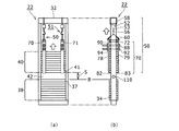
図2は、釣合おもり22と、取付支援装置50,51との関係を示す図である。釣合おもり22における釣合おもり枠24は、2つの縦枠28,30、上枠32、及び下枠33を組み合わせて形成された枠体である。2つの縦枠28,30、上枠32、及び下枠33のそれぞれは、十分な強度を有する金属材料を所定の形状に成形したものが用いられる。例えば、縦枠28,30は、おもり34の複数個を積み重ねて所定数のおもり26とする際の案内溝31を兼ねて、コの字の断面形状を有する柱材を所定の長さに加工して用いられる(図3(a)参照)。釣合おもり枠24は、これらを溶接またはボルト・ナットの締結等によって強固に結合したものが用いられる。十分な強度、強固に結合とは、釣合おもり枠24に収容される所定数のおもり26の質量に十分耐えること、及び、釣合おもり22がエレベーター10の運行によって受ける加速度や衝撃による外力に十分耐えることを意味する。
FIG. 2 is a diagram illustrating the relationship between the
釣合おもり22における所定数のおもり26は、単体としてのおもり34の所定数を釣合おもり枠24に積み重ねたおもり集合体である。図2の例では、所定数のおもり26は、18個の単体としてのおもり34で構成される。所定数のおもり26の個数=18個は例示であって、エレベーター10における乗りかご16の質量、乗りかご16の公称積載質量、単体としてのおもり34の質量、エレベーター10の運行速度仕様等に応じて、適宜変更される。
The predetermined number of
この所定数のおもり26と、後述する下方側の複数のおもり37及び上方側の複数のおもり41は、単体としてのおもり34の集合体であり、「(所定数の)おもり26」、「(複数の)おもり37」、「(複数の)おもり41」は、複数形のおもりである。単体としてのおもり34と、後述する下方側の複数のおもり38の最も上方側のおもり37及び上方側の複数のおもり40の最も下方側のおもり41は、個々のおもり単体で、「おもり34」、「おもり37」、「おもり41」は単数形のおもりである。
The predetermined number of
おもり34は、所定の平面形状と厚さとを有する平板状質量体である。所定の平面形状は略矩形形状である。略矩形形状とは、長辺と短辺とで構成される矩形形状を基本とし、長辺が延伸する方向の両端部にそれぞれ張出部35,36を有する形状である(図3(a)参照)。張出部35,36は、釣合おもり枠24におもり34を積み重ねて配置する際に、整列された積み重ねとなるように、縦枠28,30の案内溝31に嵌め込まれる部分である。したがって、おもり34がエレベーター10の釣合おもり枠24に配置されたとき、おもり34の長辺が延伸する方向は、エレベーター10の幅方向となり、おもり34の短辺が延伸する方向は、エレベーター10の奥行方向となる。図2に、おもり34の短辺寸法Wを示す。
The
取付支援装置50,51は、所定数のおもり26を構成する18個の積み重ねられたおもり34について、分離位置Bにおいて、下方側の複数のおもり38と、上方側の複数のおもり40とに分離し、上方側の複数のおもり40を吊上げる装置である。分離位置Bは、所定数の積み重ねの中間の位置にすることがよい。この場合、下方側の複数のおもり38と、上方側の複数のおもり40とは、それぞれ、9個のおもり34で構成される。吊上げは、釣合おもり枠24の上枠32を用いて行い、上方側の複数のおもり40は、縦枠28,30の案内溝31に案内されて釣合おもり枠24の枠内において行われる。吊上げ量は、補強材100の上下方向に沿った高さ寸法よりも大きく設定される。一例として、補強材100の高さ寸法を約100mmとすると、吊上げ量は約150mmに設定される。これによって、下方側の複数のおもり38と、上方側の複数のおもり40との間に、吊上げ量に応じた配置用隙間S(図10参照)が生じ、この配置用隙間Sを、補強材配置空間42として用いる。
The
上記において、取付支援装置50,51によって吊上げるのは、18個のおもり34で構成される所定数のおもり26の積み重ねの中間の位置である分離位置Bよりも上方側の複数のおもり40とした。すなわち、9個のおもり34を、上方側の複数のおもり40として吊上げる。これは、釣合おもり22に1つの補強材100を取付ける場合であって、補強材100の個数が2以上の場合には吊上げ方と吊上げ個数が異なる。
In the above description, the
一例として、30個のおもり34で構成される所定数のおもり26について2つの補強材100を取付ける場合について述べる。この場合には、所定数のおもり26を3つに分けて、下方側の10個のおもり34、中央部の10個のおもり34、上方側の10個のおもり34とする。この場合、下方側の10個のおもり34と中央部の10個のおもり34との間に1つ目の補強材100を配置し、中央部の10個のおもり34と上方側の10個のおもり34との間に2つ目の補強材100を配置する。その手順として、下方側の10個のおもり34はそのままとし、中央部の10個のおもり34と上方側の10個のおもり34の合計20個のおもり34をまとめて吊上げ、1つ目の補強材のための配置空間を形成し、そこに1つ目の補強材を配置して取付ける。その後、吊上げた20個のおもり34のうち、中央部の10個のおもり34は、1つ目の補強材の上に積み重ねる。そして、残りの上方側の10個のおもり34を吊上げ、2つ目の補強材のための配置空間を形成し、そこに2つ目の補強材を配置して取付ける。その後に、取付支援装置50,51を取り外す。こうして、{下方側の10個のおもり34の集合体}−第1の補強材−{中央部の10個のおもり34の集合体}−第2の補強材−{上方側の10個のおもり34の集合体}の配置とできる。
As an example, a case where two reinforcing
図2では、上方側の複数のおもり40に対し、幅方向に沿って2台の取付支援装置50,51を用いる例を示す。これは例示であって、所定数のおもり26を構成するおもり34の長辺の長さや、吊上げる上方側の複数のおもり40の質量によって台数を変更できる。例えば、3台以上としてもよく、場合によっては1台でもよい。2台の取付支援装置50,51は同じ構成であるので、以下では、主として取付支援装置50について述べる。
FIG. 2 shows an example in which two
取付支援装置50は、おもり保持工具70と、揚重部52と、揚重接続部60とを含む。揚重部52は、巻き出し巻き戻しができるチェーン53を内蔵する電動チェーンブロックで、手元操作部54と、ワイヤ吊上部であるフック56と、揚重部52を上枠32に取付ける取付部58とを有する。電動チェーンブロックに代えて、手動でワイヤの巻き出し巻き戻しを操作できる手動式チェーンブロックでもよい。揚重部52としては、所定数のおもり26を構成する18個のおもり34のうち、半数の9個を揚重できる装置であればチェーンブロックでなくてもよい。例えば、油圧ジャッキ等を用いてもよい。以下では、揚重部52として、電動チェーンブロックを用いるものとする。揚重接続部60は、フック56に懸架される揚重ワイヤで、おもり保持工具70のワイヤ掛部74,75(図3(b)参照)に懸架されたワイヤである。なお、取付支援装置51はおもり保持工具71を含むが、おもり保持工具71はおもり保持工具70と同じ構成を有するので、以下では、主としておもり保持工具70について説明する。
The
図2の例では、取付支援装置50,51を用いて、分離位置Bにおいて、所定数のおもり26は、下方側の複数のおもり38と、上方側の複数のおもり40とに分離される。分離される前は、下方側の複数のおもり38において最も上方側のおもり37と、上方側の複数のおもり40において最も下方側のおもり41とが隣接する。
In the example of FIG. 2, the predetermined number of
図3は、おもり保持工具70と、所定数のおもり26との関係を示す図である。図3(a)は、所定数のおもり26の分離位置Bにおいて積み重ねられた2つの隣接するおもり37,41を示し、(b)は、分離位置Bに対応して配置された状態のおもり保持工具70についての分解図である。
FIG. 3 is a view showing the relationship between the
おもり37,41は、他のおもり34と同じ形状で、長辺の延伸する方向の両端部にそれぞれ張出部35,36を有する略矩形形状である。張出部35,36は、釣合おもり枠24の縦枠28,30の案内溝31に嵌め込まれる部分である。図3(a)に、縦枠30の一部を破断図で示す。18個のおもり34はそれぞれ、所定の平面形状と厚さとを有する平板状質量体であるが、鋳物等で成形され、その端面形状は正確な垂直面でなく、幾らかの丸み等を有する。そのために、積み重ねた状態において、隣接する2つのおもり37,41の積み重ねの縁部に沿って谷部ができる。この谷部を、積み重ね谷部と呼ぶ。分離位置Bにおいて隣接する2つのおもり37,41を上下方向に分離するには、おもり37,41について、2つの長辺のそれぞれの縁部に形成される積み重ね谷部44,45を用いる。積み重ね谷部44と積み重ね谷部45との間隔は、おもり37,41の短辺寸法Wよりも小さい。
The
おもり保持工具70は、上側プレート72と、一方側フック板78と、他方側フック板79と、間隔固定具としての挟み込みボルト88,92及び締付ナット90,94とを含む。
The
上側プレート72は、長手方向に沿って所定の長さを有する平板である。おもり保持工具70が釣合おもり枠24に配置されるとき、上側プレート72の長手方向は、エレベーター10の奥行方向に平行に配置される。これは、おもり34の短辺が延伸する方向と平行な方向でもある。上側プレート72の所定の長さは、各おもり34の略矩形の平面形状の短辺寸法Wよりやや長めである。上側プレート72の長手方向の一方端部と他方端部とには、それぞれ上方側に突出する突出部が設けられる。各突出部には、上側プレート72の長手方向に貫通する穴が設けられる。これらの穴は、おもり保持工具70を揚重部52によって吊上げるときに用いる揚重接続部60である揚重ワイヤを通すワイヤ掛部74,75である。
The
一方側フック板78は、一端が上側プレート72の一方端部にヒンジ機構76によって開閉可能に取付けられ、上側プレート72から下方側に延伸し、下端部において一方側フック部82が設けられる脚部80を有する部材である。ヒンジ機構76が閉じたとき、脚部80は、上側プレート72に対し垂直方向となり、ヒンジ機構76が開いたとき、図3(b)において二点鎖線で示すように、脚部80は、上側プレート72となす角度θが鈍角となるように開く。脚部80の延伸する長さは、おもり保持工具70が保持する上方側の複数のおもり40を構成するおもり34の個数等に応じて設定される。一方側フック部82は、脚部80の下端部において側方に突出し、先端へ向かうほど先細りとなる形状を有する。突出する方向は、上側プレート72の他方端部側へ向かう方向である。
The one
他方側フック板79は、一端が上側プレート72の他方端部に取付けられ、上側プレート72から下方側に延伸し、下端部において他方側フック部83が設けられる脚部81を有する部材である。他方側フック部83も一方側フック部82と同様に、脚部81の下端部において側方に突出し、先端へ向かうほど先細りとなる形状を有する。突出する方向は、上側プレート72の一方端部側へ向かう方向であり、突出する上下方向に沿って他方側フック部83が突出する高さ位置は、一方側フック部82が突出する高さ位置と同じである。換言すれば、一方側フック板78と他方側フック板79とは、上側プレート72の長手方向の両端部に互いに対向する関係で配置される。一方側フック板78との相違は、他方側フック板79はヒンジ機構76を介さずに上側プレート72の他方端部に取付けられることである。これに代えて、ヒンジ機構76と同様のヒンジ機構を介して上側プレート72の他方端部に他方側フック板79を取付けるものとしてもよい。以下では、一方側フック板78はヒンジ機構76によって上側プレート72に対し開閉可能とし、他方側フック板79は上側プレート72に固定されるものとする。一方側フック部82と他方側フック部83は、共に先端に向かうほど先細りとなる形状を有し、互いに対向する関係で配置されるが、この2つの先細りの形状を、それぞれ積み重ね谷部44,45に入り込ませる。これによって、あたかもフォークリフトのように、おもり41を持ち上げ、保持することができ、おもり41とおもり37とを分離することができる。
The other
ヒンジ機構76が開いたときは、上側プレート72の長手方向に沿って互いに対向して配置される一方側フック部82と他方側フック部83との間隔が広がる。間隔固定具は、2組のボルト・ナットとして、挟み込みボルト88,92及び締付ナット90,94で構成され、一方側フック板78と他方側フック板79の対向する間隔が広がらないように固定するために用いる。挟み込みボルト88,92を通すために、一方側フック板78の脚部80に、ボルト通し穴84,86が設けられ、他方側フック板79の脚部81に、ボルト通し穴85,87が設けられる。ボルト通し穴84,85は、上側プレート72から測った下方側の高さ位置が同じに設定される。ボルト通し穴86,87は、上側プレート72から測った下方側の高さ位置が同じであるが、ボルト通し穴84,85の高さ位置よりも下方側である。
When the
上記では、間隔固定具として、2組の挟み込みボルト88,92及び締付ナット90,94を用いた。これに代えて、一方側フック板78の先端側と他方側フック板79の先端側を固定板に固定する方法を用いてもよい。図4は、固定板96とボルト98,99を用いて、一方側フック板78の先端側と他方側フック板79の先端側を固定する例を示す図である。図3で述べた2組のボルト・ナットは、一方側フック板78の先端側と他方側フック板79の先端側に対し遠い位置にあるので、一方側フック板78の先端側と他方側フック板79の先端側との間が開きやすい恐れがある。図4の固定板96は、一方側フック板78の先端側及び他方側フック板79の先端側にごく近い位置に設けられるので、一方側フック板78の先端側と他方側フック板79の先端側との間が開くことを効果的に抑制できる。固定板96の方法と、挟み込みボルト88,92及び締付ナット90,94を用いる方法とを併用してもよい。
In the above, two sets of pinching
上記構成の取付支援装置50,51を用いた補強材取付方法について、図5以下を用いて説明する。図5は、補強材取付方法の各工程の手順を示すフローチャートである。図6以下は、図5における各工程の手順の内容を示す図で、各図における(a)は、釣合おもり枠24等について、奥行方向の乗場13側から見た正面図であり、(b)は、乗場13側から見て右側から見た側面図である。
A reinforcing material mounting method using the mounting
補強材取付方法において、最初に、保守作業場所の設定を行う(S10)。保守作業場所は、釣合おもり枠24に補強材100を取付ける作業がしやすい場所が好ましい。その1つは、図1に示すように、乗りかご16の天井の上である。その場合、まず、保守作業員8は、図示しない保守作業用端末を用いてエレベーター10の動作モードを保守作業モードとし、昇降路12内において、乗りかご16の天井と釣合おもり22とがほぼ同じ高さ位置に並ぶように乗りかご16の停止位置を設定する。そして、乗りかご16の天井の上の機械設備配置枠内に上り、そこを保守作業場所とする。
In the reinforcing material mounting method, first, a maintenance work place is set (S10). The maintenance work place is preferably a place where the work of attaching the reinforcing
図6に、補強材取付作業を行う前の釣合おもり22を示す。釣合おもり22は、釣合おもり枠24に、所定数のおもり26が収容されたものである。所定数のおもり26は、18個のおもり34の集合体である。各おもり34は、図3(a)に関連して述べたように、釣合おもり枠24の縦枠28,30に設けられる案内溝31に案内されて、上下方向に積み重ねられる。図6(b)において、補強材100を固定するために縦枠28に設けられたボルト通し穴110を示す。隠れて図示されないが、縦枠30にも同様なボルト通し穴112が設けられる。
FIG. 6 shows the
図5に戻り、初期状態の釣合おもり22に、取付支援装置50,51が配置される(S12)。図7に、釣合おもり22において、取付支援装置50,51が釣合おもり枠24の上枠32に取付けて配置された状態を示す。取付支援装置50と取付支援装置51は、同様な構成を有し、同様に配置され、同様に操作されるので、以下では、主に、図7(b)に表われている取付支援装置50及びおもり保持工具70について述べる。
Returning to FIG. 5, the
取付支援装置50を釣合おもり枠24の上枠32に取付けて配置されるときに、おもり保持工具70の上側プレート72の長手方向は、エレベーター10の奥行方向に平行に配置される。これは、おもり34の短辺が延伸する方向と平行な方向でもある。
When the mounting
図7の段階では、挟み込みボルト88,92と締付ナット90,94は、まだ分解状態のままとされ、一方側フック板78はヒンジ機構76を介して開状態にできる。この状態で、上側プレート72を、所定数のおもり26の上方側で、一方側フック部82と他方側フック部83の先端位置が分離位置Bの高さになるように配置する。この配置とするには、図2で示すように、揚重接続部60である揚重ワイヤを上側プレート72のワイヤ掛部74,75に通し、環状ループとなるように縛り、環状ループを揚重部52のワイヤ吊上部であるフック56に懸架し、揚重部52を操作する。これにより、積み重ねられた状態の分離位置Bにおいて隣接するおもり37とおもり41の積み重ね谷部45に他方側フック部83が宛がわれ、積み重ね谷部44に一方側フック部82が宛がわれる(図3参照)。S12において、取付支援装置51及びおもり保持工具71についても同様の処理が行われる。
In the stage of FIG. 7, the sandwiching
次に、図5において、おもり37,41の間の隙間に、一方側フック部82と他方側フック部83とを入り込ませる(S14)。ここでは、図示しない適当な締付治具を用いて、互いに向かい合う一方側フック板78と他方側フック板79に対して図8に白抜矢印で示す締付力Fを与え、一方側フック部82と他方側フック部83の間隔を狭める締付操作を行う。これにより、他方側フック部83は積み重ね谷部45に入り込み、一方側フック部82は積み重ね谷部44に入り込む。締付操作は、おもり41の2つの長辺の縁部がそれぞれ一方側フック板78の脚部80の内側壁面と他方側フック板79の脚部81の内側壁面に突き当たるまで進める。
Next, in FIG. 5, the one-
他方側フック板79の脚部81の内側壁面は、上側プレート72に対して下方側に垂直であり、一方側フック板78の脚部80の内側壁面は、上側プレート72に対してヒンジ機構76が完全に閉じたときに、上側プレート72に対して下方側に垂直となる。したがって、締付操作は、一方側フック板78の脚部80の内側壁面と他方側フック板79の脚部81の内側壁面との間隔が、上側プレート72の長手方向に沿った所定の長さとなるまで進められることになる。上側プレート72の所定の長さは、各おもり34の短辺寸法Wよりやや大きいので、締付操作が進んでも、一方側フック板78の脚部80の内側壁面と他方側フック板79の脚部81の内側壁面とが対向する間隔は、各おもり34の短辺寸法Wよりやや大きい。
The inner wall surface of the
したがって、締付操作が進むにつれて、おもり41の下面が一方側フック部82の上面及び他方側フック部83の上面に保持されて上方側に移動すると共に、おもり41の上方側に積み重ねられた各おもり34も、上方側に移動する。これらの上方側への移動は、縦枠28,30の案溝31と、一方側フック板78の脚部80の内側壁面及び他方側フック板79の脚部81の内側壁面とによって案内される。これによって、分離位置Bよりも上方側の複数のおもり40は、下方側の複数のおもり38から分離される。この分離によって、おもり37の上面とおもり41の下面との間に、一方側フック部82、他方側フック部83の厚さに相当する分離隙間ΔSが生じる。S14において、取付支援装置51及びおもり保持工具71についても同様の処理が行われる。
Therefore, as the tightening operation proceeds, the lower surface of the
次に、図5において、間隔固定具の設定が行われる(S16)。ここでは、図9に示すように、挟み込みボルト88をボルト通し穴84,85に通し、締付ナット90を用いてしっかり締め付け、一方側フック板78と他方側フック板79との間隔が開かないようにする。同様に、挟み込みボルト92をボルト通し穴86,87に通し、締付ナット94を用いてしっかり締め付け、一方側フック板78と他方側フック板79との間隔が開くことを二重に防止する。その後、締付治具を外す。これによって、上方側の複数のおもり40がおもり保持工具70によってしっかり保持される。S16において、取付支援装置51及びおもり保持工具71についても同様の処理が行われる。
Next, in FIG. 5, the setting of the interval fixing tool is performed (S16). Here, as shown in FIG. 9, the clamping
上記では、図示しない締付治具を用いて、一方側フック部82と他方側フック部83の間隔を狭める締付操作を行ったが、場合によっては、間隔固定具である2組の挟み込みボルト88,92及び締付ナット90,94を用いて、同様の締付操作を行ってもよい。
In the above, a tightening operation for narrowing the distance between the one
次に、図5において、補強材配置空間42の形成が行われる(S18)。ここでは、図10に示すように、取付支援装置50において揚重部52を操作し、白抜矢印に示すように、チェーン53を短くしてフック56を上方側に移動させ、おもり保持工具70の上側プレート72に懸架された揚重接続部60を上方側に吊上げる。同様に、取付支援装置51においても、図示しない揚重部を操作し、おもり保持工具71の上側プレートに懸架された揚重接続部を上方側に吊上げる。これによって、おもり保持工具70,71の全体が上方側に移動し、下方側の複数のおもり38と、上方側の複数のおもり40との間に、上下方向に関し配置用隙間Sが形成される。配置用隙間Sは、補強材配置空間42として利用される。吊上げ量でもある配置用隙間Sの大きさは、補強材100の高さ寸法に、補強材取付作業に必要な余裕を加えて設定される。
Next, in FIG. 5, the reinforcing
次に、図5において、補強材100の取付作業が行われる(S20)。ここでは、図11に示すように、補強材配置空間42である配置用隙間Sに補強材100を配置する。補強材100の2つの短辺側には、釣合おもり枠24の縦枠28,30の固定するためのねじ穴がそれぞれ設けられているので、この2つのねじ穴を、縦枠28,30に設けられているボルト通し穴110,112(図6(b)、図10(b)参照)に合わせる。そして、固定ボルト114,116をボルト通し穴110,112に通し、固定ボルト114,116をねじ穴に噛み合わせて、補強材100を縦枠28,30にしっかり固定する。
Next, in FIG. 5, the attachment work of the reinforcing
次に、図5において、上方側の複数のおもり40を降ろす処理を行う(S22)。ここでは、図12に示すように、取付支援装置50において揚重部52を操作し、白抜矢印に示すように、チェーン53を長くしてフック56を下方側に移動させ、揚重接続部60を降ろす。同様に、取付支援装置51においても揚重部を操作し、チェーンを長くしてフックを下方側に移動させ、揚重接続部を降ろす。これによって、おもり保持工具70,71の全体が下方側に移動し、上方側のおもり40は、補強材100の上面に降りる。
Next, in FIG. 5, a process of lowering the plurality of
その後、おもり保持工具70の間隔固定具である挟み込みボルト88,92から締付ナット90,94を外してヒンジ機構76が働くようにし、一方側フック板78を開き、他方側フック板79と共に、おもり41の下面から外す。同様の処理をおもり保持工具71についても行う。そして、おもり保持工具70,71を含む取付支援装置50,51の全体を釣合おもり枠24の上枠32から外す(S24)。図13に、取付支援装置50,51を外した状態の釣合おもり23を示す。釣合おもり23は、釣合おもり枠24において、下方側から上方側に向って、下方側の複数のおもり38、補強材100、上方側の複数のおもり40が順次配置されている。ここで、補強材100は、縦枠28,30のそれぞれに固定ボルト114,116によって固定される。これによって、釣合おもり枠24の一対の縦枠28,30の間が広がることを防止できる。
Thereafter, the clamping
上記のように、釣合おもり枠24に収容されている所定数のおもり26の積み重ねの中間に補強材100を配置するために、取付支援装置50,51を用いて、所定数のおもり26を下方側の複数のおもり38と上方側のおもり30とに分離する。取付支援装置50,51は、釣合おもり枠24の上枠32に取付けられるので、下方側の複数のおもり38と上方側のおもり30とに分離する工程を含め、補強材100の配置に係る全工程において、釣合おもり22の全体の質量はほとんど変化しない。釣合おもり22の全体の質量がほとんど変化しないので、釣合おもり22と乗りかご16の質量バランスはほぼ一定で、乗りかご16と釣合おもり22の位置を固定しなくて済み、作業しやすい場所で作業が可能となる。また、ほとんどが揚重部52の操作作業で済むので、労力と作業時間を少なくできる。
As described above, in order to place the reinforcing
8 保守作業員、10 エレベーター、12 昇降路、13 乗場、14 機械室、16 乗りかご、17 保守作業スペース、18 巻上機、20 昇降ロープ、22 釣合おもり、24 釣合おもり枠、26 所定数のおもり、28,30 縦枠、31 案内溝、32 上枠、33 下枠、34,37,41 (単体としての)おもり、35,36 張出部、38 下方側の複数のおもり、40 上方側の複数のおもり、42 補強材配置空間、44,45 積み重ね谷部、50,51 (エレベーター釣合おもり枠の補強材)取付支援装置、52 揚重部、53 チェーン、54 手元操作部、56 フック(ワイヤ吊上部)、58 取付部、60 揚重接続部(揚重ワイヤ)、70,71 おもり保持工具、72 上側プレート、74,75 ワイヤ掛部、76 ヒンジ機構、78 一方側フック板、79 他方側フック板、80,81 脚部、82 一方側フック部、83 他方側フック部、84,85,86,87,110,112 ボルト通し穴、88,92 挟み込みボルト、90,94 締付ナット、96 固定板、98,99 ボルト、100 補強材、114,116 固定ボルト。 8 Maintenance workers, 10 Elevators, 12 hoistways, 13 landings, 14 machine rooms, 16 passenger cars, 17 maintenance work spaces, 18 hoisting machines, 20 lifting ropes, 22 counterweights, 24 counterweight frames, 26 predetermined Number weight, 28, 30 Vertical frame, 31 Guide groove, 32 Upper frame, 33 Lower frame, 34, 37, 41 Weight (as a single unit), 35, 36 Overhang, 38 Multiple weights on the lower side, 40 Plural weights on the upper side, 42 Reinforcing material arrangement space, 44, 45 Stack valley, 50, 51 (Reinforcement material for elevator balancing weight frame) Mounting support device, 52 Lifting unit, 53 Chain, 54 Hand control unit, 56 hooks (wire suspension upper part), 58 attachment parts, 60 lifting connection parts (lifting wires), 70, 71 weight holding tools, 72 upper plates, 74, 75 wire hanging parts, 76 Hinge mechanism, 78 One side hook plate, 79 Other side hook plate, 80, 81 Leg part, 82 One side hook part, 83 Other side hook part, 84, 85, 86, 87, 110, 112 Bolt through hole, 88 , 92 sandwiching bolt, 90, 94 tightening nut, 96 fixing plate, 98, 99 bolt, 100 reinforcing material, 114, 116 fixing bolt.
Claims (5)
積み重ねられた2つの前記おもりについて上方側の前記おもりの縁部の丸みと下方側の前記おもりの縁部の丸みとによって形成された積み重ね谷部に入り込むことができ上方側の前記おもりの下面を支持可能な形状を有するおもり保持工具と、
前記釣合おもり枠に取付け可能な揚重部と、
前記おもり保持工具と前記揚重部とを接続する揚重接続部と、
を含む、エレベーター釣合おもり枠の補強材取付支援装置。 The work of attaching a reinforcing material in the middle of the weight stacking in the counterweight of an elevator that accommodates a predetermined number of weights stacked on a counterweight frame formed by combining two vertical frames, an upper frame, and a lower frame A device for supporting
The two stacked weights can enter the stacked valley formed by the roundness of the edge of the weight on the upper side and the roundness of the edge of the weight on the lower side, and the lower surface of the weight on the upper side A weight holding tool having a supportable shape;
A lifting portion attachable to the counterweight frame;
A lifting connection portion connecting the weight holding tool and the lifting portion;
Including an elevator balancing weight frame reinforcement support device.
おもりの略矩形の平面形状における短辺寸法に対応する長さを有する上側プレートと、
一端が前記上側プレートの一方端部にヒンジ機構によって開閉可能に取付けられ、他端は、前記積み重ね谷部に入り込むことができ上方側の前記おもりの下面を支持可能な形状を有する一方側フック部を含む一方側フック板と、
一端が前記上側プレートの他方端部に取付けられ、他端は、前記積み重ね谷部に入り込むことができ上方側の前記おもりの下面を支持可能な形状を有し前記一方側フック板の前記一方側フック部に対向して配置される他方側フック部を含む他方側フック板と、
前記一方側フック板と前記他方側フック板との間隔を固定する間隔固定具と、
を備える、請求項1に記載のエレベーター釣合おもり枠の補強材取付支援装置。 The weight holding tool is
An upper plate having a length corresponding to the short side dimension of the substantially rectangular planar shape of the weight;
One end hook portion is attached to one end portion of the upper plate so as to be opened and closed by a hinge mechanism, and the other end has a shape capable of entering the stacked valley portion and supporting the lower surface of the upper weight. Including one side hook plate,
One end is attached to the other end portion of the upper plate, and the other end has a shape that can enter the stacked valley portion and can support the lower surface of the weight on the upper side, and the one side of the one-side hook plate The other side hook plate including the other side hook part disposed to face the hook part;
An interval fixing tool for fixing an interval between the one side hook plate and the other side hook plate;
The reinforcement attachment support apparatus of the elevator balance weight frame of Claim 1 provided with this.
前記上側プレートから下方側に延伸する脚部を有し、
前記一方側フック部及び前記他方側フック部は、それぞれ、
前記脚部の下端部において側方に突出し、先端へ向かうほど先細りとなる形状を有する、請求項2に記載のエレベーター釣合おもり枠の補強材取付支援装置。 The one side hook plate and the other side hook plate are respectively
Having legs extending downward from the upper plate;
The one side hook part and the other side hook part are respectively
The reinforcing material attachment support device for an elevator balancing weight frame according to claim 2, which has a shape that protrudes laterally at a lower end portion of the leg portion and tapers toward a distal end.
前記一方側フック板と前記他方側フック板の間に配置される挟み込みボルト及び締付ナットである、請求項2に記載のエレベーター釣合おもり枠の補強材取付支援装置。 The spacing fixture is
The reinforcing material attachment support device for an elevator balancing weight frame according to claim 2, wherein the holding bolt and the tightening nut are disposed between the one side hook plate and the other side hook plate.
積み重ねられた2つの前記おもりについて上方側の前記おもりの縁部の丸みと下方側の前記おもりの縁部の丸みとによって形成された積み重ね谷部に入り込むことができ上方側の前記おもりの下面を支持可能な形状を有するフック部を先端に有する一対のフック板を含むおもり保持工具、前記釣合おもり枠に取付け可能な揚重部、及び、前記おもり保持工具と前記揚重部とを接続する揚重接続部を含む取付支援装置を前記釣合おもり枠に取付けて配置する工程と、
前記所定数のおもりについて予め定めた分離位置において隣接する2つの前記おもりの前記積み重ね谷部に前記おもり保持工具の一対の前記フック部を入り込ませて前記分離位置よりも上方側の複数の前記おもりを保持し、間隔固定具を用いて一対の前記フック板との間隔を固定する工程と、
前記おもり保持工具に前記揚重接続部を懸架し、前記揚重部を前記釣合おもり枠に取付け、前記揚重部のワイヤ吊上部に前記揚重接続部を懸架し、前記揚重部を操作して、前記おもり保持工具によって保持された上方側の複数の前記おもりを吊上げて、前記分離位置よりも下方側の複数の前記おもりから前記分離位置の上方側の複数の前記おもりを分離して補強材配置空間を形成する工程と、
形成された前記補強材配置空間に前記補強材を配置し、2つの前記縦枠のそれぞれに固定する工程と、
を含む、エレベーター釣合おもり枠の補強材取付方法。 A method of attaching a reinforcing material in the middle of a stack of weights in a counterweight of an elevator that accommodates a predetermined number of weights stacked on a counterweight frame formed by combining two vertical frames, an upper frame, and a lower frame Because
The two stacked weights can enter the stacked valley formed by the roundness of the edge of the weight on the upper side and the roundness of the edge of the weight on the lower side, and the lower surface of the weight on the upper side A weight holding tool including a pair of hook plates having a hook portion having a supportable shape at the tip, a lifting portion attachable to the counterweight frame, and connecting the weight holding tool and the lifting portion Attaching and arranging an attachment support device including a lifting connection portion on the counterweight frame;
A plurality of the weights above the separation position by inserting the pair of hook portions of the weight holding tool into the stacked valley portions of the two weights adjacent to each other at a predetermined separation position with respect to the predetermined number of weights. Holding the distance between the pair of hook plates using a distance fixing tool,
The lifting connection portion is suspended from the weight holding tool, the lifting portion is attached to the counterweight frame, the lifting connection portion is suspended from a wire suspension portion of the lifting portion, and the lifting portion is The plurality of weights on the upper side held by the weight holding tool are lifted to separate the plurality of weights above the separation position from the plurality of weights below the separation position. Forming a reinforcing material arrangement space,
Arranging the reinforcing material in the formed reinforcing material arrangement space and fixing the reinforcing material to each of the two vertical frames;
A method of attaching a reinforcing material for an elevator balancing weight frame.
Priority Applications (2)
| Application Number | Priority Date | Filing Date | Title |
|---|---|---|---|
| JP2017086886A JP6382391B1 (en) | 2017-04-26 | 2017-04-26 | Elevator counterweight frame reinforcement support device and elevator balance weight frame reinforcement mounting method |
| CN201810379528.2A CN108792906B (en) | 2017-04-26 | 2018-04-25 | Reinforcement installation auxiliary device and reinforcement installation method for elevator counterweight frame |
Applications Claiming Priority (1)
| Application Number | Priority Date | Filing Date | Title |
|---|---|---|---|
| JP2017086886A JP6382391B1 (en) | 2017-04-26 | 2017-04-26 | Elevator counterweight frame reinforcement support device and elevator balance weight frame reinforcement mounting method |
Publications (2)
| Publication Number | Publication Date |
|---|---|
| JP6382391B1 true JP6382391B1 (en) | 2018-08-29 |
| JP2018184256A JP2018184256A (en) | 2018-11-22 |
Family
ID=63354883
Family Applications (1)
| Application Number | Title | Priority Date | Filing Date |
|---|---|---|---|
| JP2017086886A Active JP6382391B1 (en) | 2017-04-26 | 2017-04-26 | Elevator counterweight frame reinforcement support device and elevator balance weight frame reinforcement mounting method |
Country Status (2)
| Country | Link |
|---|---|
| JP (1) | JP6382391B1 (en) |
| CN (1) | CN108792906B (en) |
Families Citing this family (1)
| Publication number | Priority date | Publication date | Assignee | Title |
|---|---|---|---|---|
| CN114728767A (en) * | 2020-02-20 | 2022-07-08 | 三菱电机大楼技术服务株式会社 | Counterweight block carrying auxiliary tool of elevator |
Citations (5)
| Publication number | Priority date | Publication date | Assignee | Title |
|---|---|---|---|---|
| JPS62179277U (en) * | 1986-05-07 | 1987-11-13 | ||
| JP2000344445A (en) * | 1999-06-04 | 2000-12-12 | Hitachi Building Systems Co Ltd | Method and device for loading elevator counterweight |
| WO2005113403A1 (en) * | 2004-05-19 | 2005-12-01 | Otis Elevator Company | Counterweight for an elevator, ballast weights for this counterweight and elevator equipped therewith |
| JP2015054769A (en) * | 2013-09-12 | 2015-03-23 | 三菱電機ビルテクノサービス株式会社 | Connection member for elevator balance weight frame, and fitting method thereof |
| JP2016102013A (en) * | 2014-11-28 | 2016-06-02 | 東海旅客鉄道株式会社 | Article hanging metal fitting |
Family Cites Families (6)
| Publication number | Priority date | Publication date | Assignee | Title |
|---|---|---|---|---|
| JP2000177950A (en) * | 1998-12-15 | 2000-06-27 | Hitachi Building Systems Co Ltd | Method and device for loading elevator balance weight |
| JP5173627B2 (en) * | 2008-06-24 | 2013-04-03 | 東芝エレベータ株式会社 | Elevator balancing weight device |
| CN202924586U (en) * | 2012-12-14 | 2013-05-08 | 日照港集团岚山港务有限公司 | Tyre dismounting lifting appliance for loading machine |
| JP2014162634A (en) * | 2013-02-27 | 2014-09-08 | Toshiba Elevator Co Ltd | Weight variable elevator |
| JP6261418B2 (en) * | 2014-03-28 | 2018-01-17 | 三菱電機株式会社 | Elevator counterweight device and repair method thereof |
| JP5948404B1 (en) * | 2014-12-26 | 2016-07-06 | 東芝エレベータ株式会社 | Elevator counterweight and reinforcement method |
-
2017
- 2017-04-26 JP JP2017086886A patent/JP6382391B1/en active Active
-
2018
- 2018-04-25 CN CN201810379528.2A patent/CN108792906B/en active Active
Patent Citations (5)
| Publication number | Priority date | Publication date | Assignee | Title |
|---|---|---|---|---|
| JPS62179277U (en) * | 1986-05-07 | 1987-11-13 | ||
| JP2000344445A (en) * | 1999-06-04 | 2000-12-12 | Hitachi Building Systems Co Ltd | Method and device for loading elevator counterweight |
| WO2005113403A1 (en) * | 2004-05-19 | 2005-12-01 | Otis Elevator Company | Counterweight for an elevator, ballast weights for this counterweight and elevator equipped therewith |
| JP2015054769A (en) * | 2013-09-12 | 2015-03-23 | 三菱電機ビルテクノサービス株式会社 | Connection member for elevator balance weight frame, and fitting method thereof |
| JP2016102013A (en) * | 2014-11-28 | 2016-06-02 | 東海旅客鉄道株式会社 | Article hanging metal fitting |
Also Published As
| Publication number | Publication date |
|---|---|
| CN108792906A (en) | 2018-11-13 |
| CN108792906B (en) | 2022-06-24 |
| JP2018184256A (en) | 2018-11-22 |
Similar Documents
| Publication | Publication Date | Title |
|---|---|---|
| KR20070037995A (en) | Method of mounting a support means of a lift cage to a lift cage and to a lift shaft | |
| JP5264751B2 (en) | Elevator lifting device and elevator lifting method | |
| CN112239115A (en) | Method and device for installing elevator guide rails into elevator shaft | |
| JP6422570B2 (en) | Machine room-less elevator | |
| JP5065766B2 (en) | Elevator equipment | |
| JPH061568A (en) | Erection method for elevator counter weight and counter weight | |
| JP6382391B1 (en) | Elevator counterweight frame reinforcement support device and elevator balance weight frame reinforcement mounting method | |
| JP2007210703A (en) | Device and method for installing hoist machine in machine-room-less elevator | |
| JP7213362B2 (en) | Elevator equipment for construction | |
| JPH08245116A (en) | Installation engineering of elevator | |
| KR101976724B1 (en) | Method for installing elevator guide rails without a machine room | |
| JPH0734069Y2 (en) | Lifting device for car or counterweight in elevator | |
| JPWO2017141438A1 (en) | Elevator equipment | |
| JP6345820B1 (en) | Buffer clearance adjusting device and buffer clearance adjusting method | |
| JP6508438B1 (en) | Lift frame assembly support apparatus for elevator and elevator frame assembly method | |
| JPH082850A (en) | Work method in elevator shaft | |
| WO2013004899A1 (en) | Elevator, rope anchorage assembly for an elevator, and method for modernizing an elevator | |
| JP6902970B2 (en) | Guide rail installation method | |
| JP7404506B2 (en) | Construction elevator equipment and elevator main rope extension method | |
| JP7343053B2 (en) | Work floor equipment for elevator installation | |
| WO2023175881A1 (en) | Installation method for hoisting machine | |
| JP2008195487A (en) | Hanging fixture of rope-stopping mechanism for elevator | |
| JP2007186274A (en) | Method for installing elevator hoistway top part equipment | |
| WO2020261804A1 (en) | Method for laying guide rails and rotation prevention jig | |
| JP6324216B2 (en) | Car suspension device and elevator maintenance work method |
Legal Events
| Date | Code | Title | Description |
|---|---|---|---|
| A977 | Report on retrieval |
Free format text: JAPANESE INTERMEDIATE CODE: A971007 Effective date: 20180622 |
|
| TRDD | Decision of grant or rejection written | ||
| A01 | Written decision to grant a patent or to grant a registration (utility model) |
Free format text: JAPANESE INTERMEDIATE CODE: A01 Effective date: 20180703 |
|
| A61 | First payment of annual fees (during grant procedure) |
Free format text: JAPANESE INTERMEDIATE CODE: A61 Effective date: 20180801 |
|
| R150 | Certificate of patent or registration of utility model |
Ref document number: 6382391 Country of ref document: JP Free format text: JAPANESE INTERMEDIATE CODE: R150 |
|
| S533 | Written request for registration of change of name |
Free format text: JAPANESE INTERMEDIATE CODE: R313533 |
|
| R350 | Written notification of registration of transfer |
Free format text: JAPANESE INTERMEDIATE CODE: R350 |