JP5065766B2 - Elevator equipment - Google Patents
Elevator equipment Download PDFInfo
- Publication number
- JP5065766B2 JP5065766B2 JP2007136835A JP2007136835A JP5065766B2 JP 5065766 B2 JP5065766 B2 JP 5065766B2 JP 2007136835 A JP2007136835 A JP 2007136835A JP 2007136835 A JP2007136835 A JP 2007136835A JP 5065766 B2 JP5065766 B2 JP 5065766B2
- Authority
- JP
- Japan
- Prior art keywords
- rope
- bracket
- car
- lower frame
- suspension
- Prior art date
- Legal status (The legal status is an assumption and is not a legal conclusion. Google has not performed a legal analysis and makes no representation as to the accuracy of the status listed.)
- Active
Links
Images


Landscapes
- Lift-Guide Devices, And Elevator Ropes And Cables (AREA)
- Load-Engaging Elements For Cranes (AREA)
Description
本発明はエレベーター装置に係り、特に、乗かごの下部から釣合いロープを吊り下げるように構成したエレベーター装置に関する。 The present invention relates to an elevator apparatus, and more particularly to an elevator apparatus configured to suspend a balancing rope from a lower part of a passenger car.
通常、乗かごの下部から釣合いロープを吊り下げるように構成したエレベーター装置は、図1〜図3に示すように構成されている。 Normally, an elevator apparatus configured to suspend a balancing rope from the lower part of a car is configured as shown in FIGS.
即ち、エレベーター装置は、大きくは、昇降路1内に敷設されたガイドレール2に案内されて昇降する乗かご3及び釣合い錘4と、これらをつるべ式に連結する主ロープ5と、この主ロープ5を昇降路1の頂部で巻き掛けて駆動する巻上機6とを備えている。
In other words, the elevator apparatus is roughly divided into a car 3 and a counterweight 4 that are guided by a
乗かご3は、かご枠7とかご室8とより構成され、さらに、かご枠7は、左右一対の縦枠9と、この縦枠9の上部を連結する上枠10と、縦枠9の下部を連結し前記かご室8を支持する下枠11とを備えている。そして、前記かご枠7の上下部には前記ガイドレール2と係合する案内ローラや案内シューなどの案内手段12a,12bが設けられている。
The car 3 includes a car frame 7 and a car room 8. The car frame 7 further includes a pair of left and right vertical frames 9, an
このほか、前記乗かご3の下部から昇降路1の高さ方向のほぼ中間部にかけて、乗かご3内との信号の授受や乗かご内の各種駆動装置等に電力を供給するフィーダ線13が設けられている。
In addition, a
そして、乗かご3が図1に示す最上階15HFにある時の巻上機6を経由して両側に吊り下げられる主ロープ5の長さの差と、乗かご3が図2に示す最下階15LFにある時の巻上機6を経由して両側に吊り下げられる主ロープ5の長さの差とによる重量アンバランスが生じるために、釣合いロープ14を乗かご3の底部から吊り下げ、釣合い錘4の底部に連結し、主ロープ5の重量アンバランスを相殺している。
And the difference of the length of the
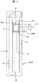
この釣合いロープ14の吊り下げ構造は、図3に示すように、断面コ字状をした一対の型鋼11a,11bからなる下枠11の下部に、型鋼11a,11bの間隔よりも長く形成されたロープ吊り下げブラケット16を締結ボルトb1,b2を締結して固定し、ロープ吊り下げブラケット16の下枠11から張り出した先端部にロープ保持具17を介して釣合いロープ14を吊り下げている。
As shown in FIG. 3, the suspension structure of the
尚、関連する技術は、例えば特許文献1に示すように、既に周知である。
The related technique is already well known as shown in
上記釣合いロープ14の吊り下げ構造によれば、締結ボルトb1,b2に作用する最大引張力は、乗かご3が図1に示す最上階15HFにあるときにつりあいロープ14の重量が最も大きくなって作用し、そのため締結ボルトb1,b2の特に、釣合いロープ14側の締結ボルトb1をこの最大引張力に耐える太さに設計しなければならない。
According to the suspension structure of the
因みに、締結ボルトb1に作用する最大引張力をR1、釣合いロープ14の最大重量をW、下枠11の型鋼11a,11bに締結された締結ボルトb1,b2の間隔をL1、締結ボルトb1から釣合いロープ14の吊り下げ位置までの寸法をL2とした場合、締結ボルトb1に作用する最大引張力をR1は、
R1=〔W×(L1+L2)/L1 …(1)
となる。
Incidentally, the maximum tensile force acting on the fastening bolt b1 is R1, the maximum weight of the
R1 = [W × (L1 + L2) / L1 (1)
It becomes.
近年、ビルの高層化により昇降路の長行程化が進み、その分、釣合いロープ14の重量Wも増加し、最大引張力R1も大きくなる傾向にある。
In recent years, the length of the hoistway has been increased due to the increase in the number of buildings, and accordingly, the weight W of the
そのために、最大引張力R1に耐えるように、締結ボルトb1もボルト径を含めて大型化しなければならない。しかしながら、締結ボルトb1を大型化すると、それに合わせてボルト締結部近傍の下枠11の型鋼11a,11bやロープ吊り下げブラケット16の寸法を大型化しなくてはならず、部品の標準化を妨げるばかりでなく、各部材の大型化により乗かご3の重量を増大させることになる。
Therefore, the fastening bolt b1 must be enlarged including the bolt diameter so as to withstand the maximum tensile force R1. However, when the size of the fastening bolt b1 is increased, the dimensions of the
本発明の目的は、ロープ吊り下げブラケットを下枠に締結する締結ボルトに作用する最大引張力を低減できる釣合いロープの吊り下げ構造を有するエレベーター装置を提供することにある。 The objective of this invention is providing the elevator apparatus which has the suspension structure of the balance rope which can reduce the maximum tensile force which acts on the fastening bolt which fastens a rope suspension bracket to a lower frame.
本発明は上記目的を達成するために、釣合いロープを吊り下げるロープ吊り下げブラケットを、第1の吊り下げブラケットと第2の吊り下げブラケットとで構成し、前記第1の吊り下げブラケットを前記下枠の上側に位置させてボルト締結し、前記第2の吊り下げブラケットを前記下枠の上側にブラケット台を介して位置させてボルト締結し、第1及び第2の吊り下げブラケットは複数本の釣合いロープを夫々前記下枠から同距離の位置に吊り下げるようにしたのである。 In order to achieve the above object, according to the present invention, a rope suspension bracket for suspending a balancing rope is composed of a first suspension bracket and a second suspension bracket, and the first suspension bracket is the lower suspension bracket. Bolts are fastened by being positioned on the upper side of the frame, the second suspension brackets are fastened by bolts by being positioned on the upper side of the lower frame via a bracket base, and a plurality of first and second suspension brackets may be provided. The balancing ropes are respectively suspended from the lower frame at the same distance .
このように、ロープ吊り下げブラケットを下枠の上側に固定することで、釣合いロープ側の締結ボルトの締結位置を支点として釣合いロープから離れた側の締結ボルトに引張力が作用する。その結果、釣合いロープの重量のほとんどを前記支点となる位置の下枠によって支えるので、釣合いロープから離れた側の締結ボルトに作用する引張力を低減することができるのである。 Thus, by fixing the rope suspension bracket to the upper side of the lower frame, a tensile force acts on the fastening bolt on the side away from the balancing rope with the fastening position of the fastening bolt on the balancing rope side as a fulcrum. As a result, most of the weight of the balance rope is supported by the lower frame at the position serving as the fulcrum, so that the tensile force acting on the fastening bolt on the side away from the balance rope can be reduced.
以上説明したように本発明によれば、ロープ吊り下げブラケットを下枠に締結する締結ボルトに作用する最大引張力を低減できる釣合いロープの吊り下げ構造を有するエレベーター装置を得ることができる。 As described above, according to the present invention, an elevator apparatus having a balance rope suspension structure that can reduce the maximum tensile force acting on the fastening bolt that fastens the rope suspension bracket to the lower frame can be obtained.
以下本発明によるエレベーター装置の一実施の形態を図4に基づいて説明する。尚、エレベーター装置としての基本構成は、図1及び図2に示された構成と同じであるので、再度の詳細な説明は省略し、釣合いロープの吊り下げ構造についてのみ説明する。 Hereinafter, an embodiment of an elevator apparatus according to the present invention will be described with reference to FIG. In addition, since the basic composition as an elevator apparatus is the same as the structure shown by FIG.1 and FIG.2, detailed description is abbreviate | omitted again and only the suspension structure of a balance rope is demonstrated.
下枠11を構成し間隔をおいて対向配置された型鋼11a,11bの上部にロープ吊り下げブラケット16を配置する。このとき、ロープ吊り下げブラケット16の一端側は型鋼11aから張り出さないようにし、他端側は型鋼11bから張り出して延在させる。
A
このように配置されたロープ吊り下げブラケット16を、締結ボルトB1,B2によって夫々型鋼11a,11b上に締結して固定する。固定されたロープ吊り下げブラケット16の型鋼11bから張り出した延在端部には、ロープ保持具17を介して釣合いロープ14を吊り下げている。
The
このように構成することで、釣合いロープ14側の型鋼11bの締結ボルトB1部分を支点として、てこの作用によって、釣合いロープ14とは反対側の型鋼11aの締結ボルトB2に釣合いロープ14の重量の反力が作用する。したがって、締結ボルトB2に最大引張力が作用する。
With this configuration, the fastening bolt B1 portion of the
ここで、下枠11の型鋼11a,11bの大きさ間隔、ロープ吊り下げブラケット16の大きさ、釣合いロープ14の吊り下げ位置や重量を、図3に示す釣合いロープの吊り下げ構造と同じにし、このときの締結ボルトB2に作用する最大引張力をR2とすると、最大引張力R2は、
R2=(W×L2)/L1 …(2)
となる。
Here, the size interval of the
R2 = (W × L2) / L1 (2)
It becomes.
そして、上記(1)式と(2)式とを比較すると、本実施の形態による最大引張力R2は、釣合いロープ14の最大重量Wの分だけ低減することができる。
When comparing the above formulas (1) and (2), the maximum tensile force R2 according to the present embodiment can be reduced by the maximum weight W of the
したがって本実施の形態によれば、締結ボルトB1,B2の径を太くしたりする必要はなく、その結果、ボルト締結部近傍の下枠11の型鋼11a,11bやロープ吊り下げブラケット16の寸法を大型化する必要はなくなって標準の部品を使用することができ、かつ、各部材の大型化による乗かご3の重量増大をなくすことができる。
Therefore, according to the present embodiment, it is not necessary to increase the diameter of the fastening bolts B1, B2, and as a result, the dimensions of the
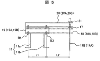
次に、釣合いロープを多数本吊り下げる場合(この場合には5本)の釣合いロープの吊り下げ構造について、図5〜図7に示す変形例に基づいて説明する。 Next, a structure for suspending a balance rope when a large number of balance ropes are suspended (in this case, five) will be described based on the modifications shown in FIGS.
この変形例において、下枠11を構成するコ字状の型鋼11a,11bの上側に、第1の吊り下げブラケットとなるロープ吊り下げ下段ブラケット18と第2の吊り下げブラケットとなるロープ吊り下げ上段ブラケット20の夫々を締結ボルトB1,B2,B3,B4を用いて締結して多段に固定している。
In this modification, on the upper side of the U-shaped
ロープ吊り下げ下段ブラケット18は、二つの型鋼11a,11bを交差する左右一対の下ブラケット18A,18Bを、前記実施の形態の図4と同じように、締結ボルトB1,B2を用いて型鋼11a,11bに固定する。そして、下ブラケット18A,18Bの端部間にロープ保持具17を跨らせ、そこから2本の釣合いロープ14Aを吊り下げている。
The rope hanging
一方、ロープ吊り下げ上段ブラケット20も左右一対の上ブラケット20A,20Bからなり、これら上ブラケット20A,20Bは、二つの型鋼11a,11bの上に交差するように締結ボルトB3,B4で固定された左右一対のブラケット台19(19A,19B)上に平行となるように締結ボルトによって固定されている。そして、上ブラケット20A,20Bの端部間にロープ保持具21を跨らせ、そこから3本の釣合いロープ14Bを吊り下げている。この3本の釣合いロープ14Bは、下段に位置するロープ保持具17に形成した貫通孔17Hを貫通して吊り下げられ、前記下段の釣合いロープ14Aと同じように、下枠11の型鋼11bから同距離の位置から吊り下げられている。
On the other hand, the rope hanging
このように、下枠11を構成するコ字状の型鋼11a,11bの上側に、ロープ吊り下げ下段ブラケット18とロープ吊り下げ上段ブラケット20を多段に設置することで、締結ボルトB1、B3に作用する最大引張力を前記実施の形態と同理由によって低減できると共に、5本の釣合いロープ14A,14Bの重量を分散することができるので、より締結ボルトB1、B3に作用する最大引張力を低減することができる。
In this way, by installing the rope hanging
尚、本変形例は、前記実施の形態に較べて釣合いロープの本数を多くしたものであるが、長行程の昇降路を昇降するエレベーター装置においては、ロープ本数が5本以下の場合のでも、本変形例のようにロープ吊り下げ下段ブラケット18とロープ吊り下げ上段ブラケット20を多段に設置するようにして、締結ボルトB1、B3に作用する最大引張力を低減するようにしてもよい。
In this modification, the number of balancing ropes is increased compared to the above embodiment, but in an elevator apparatus that lifts and lowers a long stroke hoistway, even when the number of ropes is 5 or less, As in the present modification, the rope hanging
1…昇降路、2…ガイドレール、3…乗かご、4…釣合い錘、5…主ロープ、6…巻上機、7…かご枠、8…かご室、9…縦枠、10…上枠、11…下枠、11a,11b…型鋼、12a,12b…案内手段、13…フィーダ線、14,14A,14B…釣合いロープ、15HF…最上階、15LF…最下階、16…ロープ吊り下げブラケット、17,21…ロープ保持具、17H…貫通孔、18…ロープ吊り下げ上段ブラケット、18A,18B…下ブラケット、19,19A,19B…ブラケット台、20…ロープ吊り下げ上段ブラケット、20A,20B…上ブラケット、B1,B2,B3,B4…締結ボルト。
DESCRIPTION OF
Claims (1)
Priority Applications (3)
| Application Number | Priority Date | Filing Date | Title |
|---|---|---|---|
| JP2007136835A JP5065766B2 (en) | 2007-05-23 | 2007-05-23 | Elevator equipment |
| CN2008101091657A CN101311098B (en) | 2007-05-23 | 2008-05-23 | Elevator device |
| HK09102693.7A HK1122263A1 (en) | 2007-05-23 | 2009-03-20 | Elevator device |
Applications Claiming Priority (1)
| Application Number | Priority Date | Filing Date | Title |
|---|---|---|---|
| JP2007136835A JP5065766B2 (en) | 2007-05-23 | 2007-05-23 | Elevator equipment |
Publications (2)
| Publication Number | Publication Date |
|---|---|
| JP2008290828A JP2008290828A (en) | 2008-12-04 |
| JP5065766B2 true JP5065766B2 (en) | 2012-11-07 |
Family
ID=40099957
Family Applications (1)
| Application Number | Title | Priority Date | Filing Date |
|---|---|---|---|
| JP2007136835A Active JP5065766B2 (en) | 2007-05-23 | 2007-05-23 | Elevator equipment |
Country Status (3)
| Country | Link |
|---|---|
| JP (1) | JP5065766B2 (en) |
| CN (1) | CN101311098B (en) |
| HK (1) | HK1122263A1 (en) |
Families Citing this family (6)
| Publication number | Priority date | Publication date | Assignee | Title |
|---|---|---|---|---|
| JP2010285277A (en) * | 2009-06-15 | 2010-12-24 | Toshiba Elevator Co Ltd | Live load detecting device of elevator |
| CN102219143A (en) * | 2011-05-31 | 2011-10-19 | 江南嘉捷电梯股份有限公司 | Weight compensation device on underframe of elevator carriage |
| CN104444710A (en) * | 2014-09-28 | 2015-03-25 | 苏州福沃斯电梯有限公司 | Elevator |
| JP6404168B2 (en) * | 2015-04-02 | 2018-10-10 | 株式会社日立製作所 | Elevator equipment |
| CN108639883A (en) * | 2018-07-30 | 2018-10-12 | 沃克斯电梯(中国)有限公司 | The bistable magnetic swich and magnet mounting bracket used in deceleration of elevator |
| CN115667115A (en) * | 2020-05-26 | 2023-01-31 | 株式会社日立制作所 | Elevator cage |
Family Cites Families (5)
| Publication number | Priority date | Publication date | Assignee | Title |
|---|---|---|---|---|
| JPS59162567U (en) * | 1984-03-23 | 1984-10-31 | 株式会社日立製作所 | Elevator balance rope device |
| JP2608185B2 (en) * | 1991-02-18 | 1997-05-07 | 三菱電機ビルテクノサービス株式会社 | Elevator balance weight device |
| JPH07228448A (en) * | 1994-02-17 | 1995-08-29 | Toshiba Corp | Compensating rope fitting structure for elevator |
| KR101005395B1 (en) * | 2003-06-20 | 2010-12-30 | 오티스 엘리베이터 컴파니 | Compact bedplate with integrated, accessible dead end hitches |
| JP2005162349A (en) * | 2003-11-28 | 2005-06-23 | Mitsubishi Electric Corp | Elevator car floor device |
-
2007
- 2007-05-23 JP JP2007136835A patent/JP5065766B2/en active Active
-
2008
- 2008-05-23 CN CN2008101091657A patent/CN101311098B/en active Active
-
2009
- 2009-03-20 HK HK09102693.7A patent/HK1122263A1/en not_active IP Right Cessation
Also Published As
| Publication number | Publication date |
|---|---|
| JP2008290828A (en) | 2008-12-04 |
| HK1122263A1 (en) | 2009-05-15 |
| CN101311098B (en) | 2011-04-20 |
| CN101311098A (en) | 2008-11-26 |
Similar Documents
| Publication | Publication Date | Title |
|---|---|---|
| JP5065766B2 (en) | Elevator equipment | |
| JP5264751B2 (en) | Elevator lifting device and elevator lifting method | |
| JP4833225B2 (en) | Compensation in elevator systems with multiple cars in one hoistway | |
| JP2006264862A (en) | Elevator without machine room | |
| JP4774429B2 (en) | Elevator equipment | |
| KR100780499B1 (en) | Machine room-less elevator system | |
| JP5001013B2 (en) | Elevator equipment | |
| JP6738964B2 (en) | Elevator | |
| JPH1081468A (en) | Elevator | |
| JP4091326B2 (en) | Elevator equipment | |
| JP2011190047A (en) | Elevator device | |
| JP5278359B2 (en) | Renewal method of hydraulic elevator and rope type elevator renewed by the method | |
| JP5665666B2 (en) | Elevator equipment | |
| JP2013067492A (en) | Device for fixing hoisting machine of elevator | |
| JP2006282368A (en) | Elevator device | |
| JP2012201497A (en) | Machine bed and lifting device | |
| JP7556181B2 (en) | How to install the hoist | |
| KR20180101486A (en) | Elevator device | |
| JP6684473B2 (en) | Elevator with multiple counterweights | |
| JP4307904B2 (en) | Elevator return wheel support device | |
| JP6267253B2 (en) | Elevator structure | |
| WO2013004899A1 (en) | Elevator, rope anchorage assembly for an elevator, and method for modernizing an elevator | |
| JP7362922B2 (en) | elevator car | |
| JP2015013713A (en) | Compensating chain device and elevator device | |
| JP2008207939A (en) | Rope type elevator |
Legal Events
| Date | Code | Title | Description |
|---|---|---|---|
| A621 | Written request for application examination |
Free format text: JAPANESE INTERMEDIATE CODE: A621 Effective date: 20090805 |
|
| A977 | Report on retrieval |
Free format text: JAPANESE INTERMEDIATE CODE: A971007 Effective date: 20111104 |
|
| A131 | Notification of reasons for refusal |
Free format text: JAPANESE INTERMEDIATE CODE: A131 Effective date: 20111108 |
|
| A521 | Written amendment |
Free format text: JAPANESE INTERMEDIATE CODE: A523 Effective date: 20120105 |
|
| TRDD | Decision of grant or rejection written | ||
| A01 | Written decision to grant a patent or to grant a registration (utility model) |
Free format text: JAPANESE INTERMEDIATE CODE: A01 Effective date: 20120807 |
|
| A01 | Written decision to grant a patent or to grant a registration (utility model) |
Free format text: JAPANESE INTERMEDIATE CODE: A01 |
|
| A61 | First payment of annual fees (during grant procedure) |
Free format text: JAPANESE INTERMEDIATE CODE: A61 Effective date: 20120810 |
|
| R150 | Certificate of patent or registration of utility model |
Ref document number: 5065766 Country of ref document: JP Free format text: JAPANESE INTERMEDIATE CODE: R150 Free format text: JAPANESE INTERMEDIATE CODE: R150 |
|
| FPAY | Renewal fee payment (event date is renewal date of database) |
Free format text: PAYMENT UNTIL: 20150817 Year of fee payment: 3 |