JP6337106B2 - Wooden panel element - Google Patents
Wooden panel element Download PDFInfo
- Publication number
- JP6337106B2 JP6337106B2 JP2016522446A JP2016522446A JP6337106B2 JP 6337106 B2 JP6337106 B2 JP 6337106B2 JP 2016522446 A JP2016522446 A JP 2016522446A JP 2016522446 A JP2016522446 A JP 2016522446A JP 6337106 B2 JP6337106 B2 JP 6337106B2
- Authority
- JP
- Japan
- Prior art keywords
- board
- panel element
- layer
- width
- notch
- Prior art date
- Legal status (The legal status is an assumption and is not a legal conclusion. Google has not performed a legal analysis and makes no representation as to the accuracy of the status listed.)
- Expired - Fee Related
Links
Images


Classifications
-
- B—PERFORMING OPERATIONS; TRANSPORTING
- B32—LAYERED PRODUCTS
- B32B—LAYERED PRODUCTS, i.e. PRODUCTS BUILT-UP OF STRATA OF FLAT OR NON-FLAT, e.g. CELLULAR OR HONEYCOMB, FORM
- B32B3/00—Layered products comprising a layer with external or internal discontinuities or unevennesses, or a layer of non-planar form; Layered products having particular features of form
- B32B3/10—Layered products comprising a layer with external or internal discontinuities or unevennesses, or a layer of non-planar form; Layered products having particular features of form characterised by a discontinuous layer, i.e. formed of separate pieces of material
- B32B3/14—Layered products comprising a layer with external or internal discontinuities or unevennesses, or a layer of non-planar form; Layered products having particular features of form characterised by a discontinuous layer, i.e. formed of separate pieces of material characterised by a face layer formed of separate pieces of material which are juxtaposed side-by-side
-
- B—PERFORMING OPERATIONS; TRANSPORTING
- B32—LAYERED PRODUCTS
- B32B—LAYERED PRODUCTS, i.e. PRODUCTS BUILT-UP OF STRATA OF FLAT OR NON-FLAT, e.g. CELLULAR OR HONEYCOMB, FORM
- B32B7/00—Layered products characterised by the relation between layers; Layered products characterised by the relative orientation of features between layers, or by the relative values of a measurable parameter between layers, i.e. products comprising layers having different physical, chemical or physicochemical properties; Layered products characterised by the interconnection of layers
- B32B7/04—Interconnection of layers
- B32B7/08—Interconnection of layers by mechanical means
-
- B—PERFORMING OPERATIONS; TRANSPORTING
- B27—WORKING OR PRESERVING WOOD OR SIMILAR MATERIAL; NAILING OR STAPLING MACHINES IN GENERAL
- B27M—WORKING OF WOOD NOT PROVIDED FOR IN SUBCLASSES B27B - B27L; MANUFACTURE OF SPECIFIC WOODEN ARTICLES
- B27M3/00—Manufacture or reconditioning of specific semi-finished or finished articles
- B27M3/0013—Manufacture or reconditioning of specific semi-finished or finished articles of composite or compound articles
- B27M3/0026—Manufacture or reconditioning of specific semi-finished or finished articles of composite or compound articles characterised by oblong elements connected laterally
-
- B—PERFORMING OPERATIONS; TRANSPORTING
- B27—WORKING OR PRESERVING WOOD OR SIMILAR MATERIAL; NAILING OR STAPLING MACHINES IN GENERAL
- B27M—WORKING OF WOOD NOT PROVIDED FOR IN SUBCLASSES B27B - B27L; MANUFACTURE OF SPECIFIC WOODEN ARTICLES
- B27M3/00—Manufacture or reconditioning of specific semi-finished or finished articles
- B27M3/0013—Manufacture or reconditioning of specific semi-finished or finished articles of composite or compound articles
- B27M3/0066—Manufacture or reconditioning of specific semi-finished or finished articles of composite or compound articles characterised by tongue and groove or tap hole connections
-
- B—PERFORMING OPERATIONS; TRANSPORTING
- B32—LAYERED PRODUCTS
- B32B—LAYERED PRODUCTS, i.e. PRODUCTS BUILT-UP OF STRATA OF FLAT OR NON-FLAT, e.g. CELLULAR OR HONEYCOMB, FORM
- B32B21/00—Layered products comprising a layer of wood, e.g. wood board, veneer, wood particle board
- B32B21/13—Layered products comprising a layer of wood, e.g. wood board, veneer, wood particle board all layers being exclusively wood
-
- B—PERFORMING OPERATIONS; TRANSPORTING
- B32—LAYERED PRODUCTS
- B32B—LAYERED PRODUCTS, i.e. PRODUCTS BUILT-UP OF STRATA OF FLAT OR NON-FLAT, e.g. CELLULAR OR HONEYCOMB, FORM
- B32B3/00—Layered products comprising a layer with external or internal discontinuities or unevennesses, or a layer of non-planar form; Layered products having particular features of form
- B32B3/26—Layered products comprising a layer with external or internal discontinuities or unevennesses, or a layer of non-planar form; Layered products having particular features of form characterised by a particular shape of the outline of the cross-section of a continuous layer; characterised by a layer with cavities or internal voids ; characterised by an apertured layer
- B32B3/30—Layered products comprising a layer with external or internal discontinuities or unevennesses, or a layer of non-planar form; Layered products having particular features of form characterised by a particular shape of the outline of the cross-section of a continuous layer; characterised by a layer with cavities or internal voids ; characterised by an apertured layer characterised by a layer formed with recesses or projections, e.g. hollows, grooves, protuberances, ribs
-
- B—PERFORMING OPERATIONS; TRANSPORTING
- B32—LAYERED PRODUCTS
- B32B—LAYERED PRODUCTS, i.e. PRODUCTS BUILT-UP OF STRATA OF FLAT OR NON-FLAT, e.g. CELLULAR OR HONEYCOMB, FORM
- B32B7/00—Layered products characterised by the relation between layers; Layered products characterised by the relative orientation of features between layers, or by the relative values of a measurable parameter between layers, i.e. products comprising layers having different physical, chemical or physicochemical properties; Layered products characterised by the interconnection of layers
- B32B7/03—Layered products characterised by the relation between layers; Layered products characterised by the relative orientation of features between layers, or by the relative values of a measurable parameter between layers, i.e. products comprising layers having different physical, chemical or physicochemical properties; Layered products characterised by the interconnection of layers with respect to the orientation of features
-
- E—FIXED CONSTRUCTIONS
- E04—BUILDING
- E04C—STRUCTURAL ELEMENTS; BUILDING MATERIALS
- E04C2/00—Building elements of relatively thin form for the construction of parts of buildings, e.g. sheet materials, slabs, or panels
- E04C2/02—Building elements of relatively thin form for the construction of parts of buildings, e.g. sheet materials, slabs, or panels characterised by specified materials
- E04C2/10—Building elements of relatively thin form for the construction of parts of buildings, e.g. sheet materials, slabs, or panels characterised by specified materials of wood, fibres, chips, vegetable stems, or the like; of plastics; of foamed products
- E04C2/12—Building elements of relatively thin form for the construction of parts of buildings, e.g. sheet materials, slabs, or panels characterised by specified materials of wood, fibres, chips, vegetable stems, or the like; of plastics; of foamed products of solid wood
- E04C2/14—Building elements of relatively thin form for the construction of parts of buildings, e.g. sheet materials, slabs, or panels characterised by specified materials of wood, fibres, chips, vegetable stems, or the like; of plastics; of foamed products of solid wood reinforced
-
- E—FIXED CONSTRUCTIONS
- E04—BUILDING
- E04C—STRUCTURAL ELEMENTS; BUILDING MATERIALS
- E04C2/00—Building elements of relatively thin form for the construction of parts of buildings, e.g. sheet materials, slabs, or panels
- E04C2/30—Building elements of relatively thin form for the construction of parts of buildings, e.g. sheet materials, slabs, or panels characterised by the shape or structure
- E04C2/34—Building elements of relatively thin form for the construction of parts of buildings, e.g. sheet materials, slabs, or panels characterised by the shape or structure composed of two or more spaced sheet-like parts
-
- E—FIXED CONSTRUCTIONS
- E04—BUILDING
- E04C—STRUCTURAL ELEMENTS; BUILDING MATERIALS
- E04C2/00—Building elements of relatively thin form for the construction of parts of buildings, e.g. sheet materials, slabs, or panels
- E04C2/44—Building elements of relatively thin form for the construction of parts of buildings, e.g. sheet materials, slabs, or panels characterised by the purpose
- E04C2/46—Building elements of relatively thin form for the construction of parts of buildings, e.g. sheet materials, slabs, or panels characterised by the purpose specially adapted for making walls
-
- E—FIXED CONSTRUCTIONS
- E04—BUILDING
- E04C—STRUCTURAL ELEMENTS; BUILDING MATERIALS
- E04C2/00—Building elements of relatively thin form for the construction of parts of buildings, e.g. sheet materials, slabs, or panels
- E04C2/44—Building elements of relatively thin form for the construction of parts of buildings, e.g. sheet materials, slabs, or panels characterised by the purpose
- E04C2/50—Self-supporting slabs specially adapted for making floors ceilings, or roofs, e.g. able to be loaded
-
- B—PERFORMING OPERATIONS; TRANSPORTING
- B32—LAYERED PRODUCTS
- B32B—LAYERED PRODUCTS, i.e. PRODUCTS BUILT-UP OF STRATA OF FLAT OR NON-FLAT, e.g. CELLULAR OR HONEYCOMB, FORM
- B32B2307/00—Properties of the layers or laminate
- B32B2307/50—Properties of the layers or laminate having particular mechanical properties
- B32B2307/546—Flexural strength; Flexion stiffness
-
- B—PERFORMING OPERATIONS; TRANSPORTING
- B32—LAYERED PRODUCTS
- B32B—LAYERED PRODUCTS, i.e. PRODUCTS BUILT-UP OF STRATA OF FLAT OR NON-FLAT, e.g. CELLULAR OR HONEYCOMB, FORM
- B32B2307/00—Properties of the layers or laminate
- B32B2307/70—Other properties
- B32B2307/732—Dimensional properties
- B32B2307/734—Dimensional stability
-
- B—PERFORMING OPERATIONS; TRANSPORTING
- B32—LAYERED PRODUCTS
- B32B—LAYERED PRODUCTS, i.e. PRODUCTS BUILT-UP OF STRATA OF FLAT OR NON-FLAT, e.g. CELLULAR OR HONEYCOMB, FORM
- B32B2419/00—Buildings or parts thereof
-
- B—PERFORMING OPERATIONS; TRANSPORTING
- B32—LAYERED PRODUCTS
- B32B—LAYERED PRODUCTS, i.e. PRODUCTS BUILT-UP OF STRATA OF FLAT OR NON-FLAT, e.g. CELLULAR OR HONEYCOMB, FORM
- B32B2607/00—Walls, panels
Description
本発明は、請求項1及び15の上位概念における特徴に相応する木製のパネルエレメント、もしくは木製のビームに関する。
The invention relates to a wooden panel element or a wooden beam corresponding to the features in the superordinate concept of
材料として木材を使用する数多くの用途のうちの1つとして、例えばログハウス建築様式のような伝統的建築形態において建造物を建築する際に、建築材料として木材を使用することが挙げられる。しかしながら建築材料としての木材の需要が高まることにより、木材はプレハブ住宅においても、また建造物の新築時にもますます重要になってきている。特にある程度の規模で、プレハブ式に製作されたより大型の壁エレメントが使用されている。このような木製のパネル状エレメントは、壁エレメントとして使用する他に、床及び天井の製造のためにも使用することができる。木製の壁エレメントの他に、グルーラム(Leimbinder)とも呼ばれる集成木材から成る支持材も重要である。このような支持材は、柱として、又は屋根組のための支持構造部分として使用することができる。 One of the many uses that use wood as a material is the use of wood as a building material when building a building in a traditional architectural form, such as a log house architectural style. However, with the growing demand for timber as a building material, timber is becoming increasingly important both in prefabricated houses and when building new constructions. Larger wall elements made in prefabricated fashion are used, in particular on a certain scale. Such wooden panel-like elements can be used not only as wall elements but also for the production of floors and ceilings. In addition to the wooden wall elements, supports made of laminated timber, also called Leimbinder, are also important. Such a support can be used as a pillar or as a support structure part for a roofing set.
健康意識が多くの人々の中で高まっており、そしてこれにより住環境の改善が期待されるため、このようなパネルエレメントの製造時に、添加剤、例えば木材部分を結合するための接着剤を省くことがますます注目されている。 Occurrence of health benefits among many people, and this is expected to improve the living environment, so omit additives, such as adhesives for bonding wood parts, when manufacturing such panel elements It is getting more and more attention.
従来技術に基づいて、特許文献1及び2に記載されているように、建造物壁エレメントが既に公知である。特許文献3に記載された、木製の積層結合パネルの形態を成す建造物壁エレメントは、それぞれ層状に相並んで配置された木材から成る少なくとも2つの層を備えている。両方の層は互いに対向する溝と、溝内に挿入される鳩尾レールとによって互いに結合されている。他方において、特許文献4には、平行に向けられた複数の木材を結合して1つのエレメントに形成した構造部分が記載されている。木材を互いに結合するために、互いに向き合う長手側に隆起部及び凹部が、長手方向延在長さに沿って成形されている。隆起部もしくは凹部の断面は鳩尾形継手の形式で形成されており、木材もしくは木材部分はこれに相応して形状結合的に接合されている。 Based on the prior art, building wall elements are already known, as described in US Pat. The building wall element described in US Pat. No. 6,057,017 in the form of a wooden laminated bonded panel comprises at least two layers of wood, each arranged side by side in layers. Both layers are connected to each other by grooves facing each other and pigeontail rails inserted into the grooves. On the other hand, Patent Document 4 describes a structural portion formed by combining a plurality of parallel-oriented timbers into one element. In order to bond the wood together, a ridge and a recess are formed along the longitudinal extension length on the long sides facing each other. The cross section of the ridge or recess is formed in the form of a pigeon tail joint, and the timber or timber part is correspondingly joined in a shape-bonding manner.
本発明の課題は、建造物を建築するときに構造形成部分として使用することができる木製のパネルエレメントもしくは木製のビームを提供することである。 An object of the present invention is to provide a wooden panel element or a wooden beam that can be used as a structure-forming part when building a building.
本発明の課題は、それぞれ平行に相並んで配置されたボードから形成された少なくとも2つの層から成る木製のパネルエレメントであって、第1層のボードが第2層のボードに対して平行に向けられており、第1層のボードと第2層のボードとが鳩尾形継手(蟻継ぎ)によって互いに結合されており、鳩尾形継手が、ボードの長手方向延在長さの方向に連続する、鳩尾形の切り欠きと突起とから成る、ボード内に成形された列によって形成されている、パネルエレメントによって解決される。切り欠き及び突起はボードの幅の方向に延びており、第1層のボードと第2層のボードとが前記幅の方向に互いに位置ずれし且つ互いにオーバーラップして配置されており、鳩尾形継手の切り欠きがボード縁部からボード中央へ向かって楔状にテーパした状態で形成されている。このことの利点は、パネルエレメントの製造時に、ボードをその接触面で密に相並ぶ状態で接合できることである。またその結果、こうして製造されたパネルエレメントの高い断熱作用が達成される。さらに、このように構成されたパネルエレメントは高い内部剛性及び形状安定性をも有する。 An object of the present invention is a wooden panel element consisting of at least two layers, each formed from boards arranged side by side in parallel, wherein the first layer board is parallel to the second layer board. The first layer board and the second layer board are connected to each other by a dovetail joint (ant joint), and the dovetail joint is continuous in the direction of the longitudinally extending length of the board. This is solved by a panel element, which is formed by a row of dovetail cutouts and projections molded into a board. The notches and protrusions extend in the width direction of the board, and the first layer board and the second layer board are arranged so as to be displaced from each other in the width direction and overlap each other. The notch of the joint is formed in a state of tapering in a wedge shape from the board edge toward the center of the board. The advantage of this is that the boards can be joined closely together at their contact surfaces during the manufacture of the panel element. As a result, the high thermal insulation effect of the panel element thus manufactured is achieved. Furthermore, the panel element thus configured also has high internal rigidity and shape stability.
鳩尾形継手の切り欠きが両側で、半楔角(halber Keilwinkel)の値が0.5°〜10°、好ましくは3°〜10°の傾斜位置を有していることにより、ボードを組み立ててパネルエレメントにすることが容易になるとともに、高い内部強度及び安定性が得られる。 Assembling the board by having notches on the dovetail joints on both sides, with a halber Keilwinkel value of 0.5 ° to 10 °, preferably 3 ° to 10 °. It becomes easy to make a panel element, and high internal strength and stability are obtained.
第1層のボードと第2層のボードとが、前記ボード幅の10%以上の値のオーバーラップ幅にわたってオーバーラップしている、パネルエレメントの構成の利点は、ボードによって形成されたパネルエレメント構造の形状安定性が高められることである。 The advantage of the configuration of the panel element that the board of the first layer and the board of the second layer overlap with each other over an overlap width of 10% or more of the board width is the panel element structure formed by the board The shape stability of the is improved.
パネルエレメントの別の構成によれば、切り欠きの寸法に対する突起の寸法が、それぞれ1つの層のボードがギャップなしに互いに接触するように選択されている。このことの利点は、パネルエレメントの有効厚さが相応に大きくなることにより、パネルエレメントの断熱作用が高められることである。 According to another configuration of the panel elements, the dimensions of the protrusions relative to the dimensions of the notches are chosen such that each one-layer board contacts each other without a gap. The advantage of this is that the effective insulation of the panel element is enhanced by a correspondingly increased effective thickness of the panel element.
パネルエレメントにおいてオーバーラップ幅の値が、ボードの幅のほぼ半分に相当し、そして1つの層内に位置する互いに隣接するボード間には、実矧ぎ(Nut-Spund-Verbindung)が形成されていることにより、パネルエレメントの絶縁もしくは断熱作用が改善されるとともに、実矧ぎによって付加的な摩擦力結合作用が得られることによってボード間の結合が強化される。 In the panel element, the value of the overlap width corresponds to almost half of the width of the board, and a Nut-Spund-Verbindung is formed between adjacent boards located in one layer. As a result, the insulation or heat insulating effect of the panel element is improved, and the coupling between the boards is strengthened by obtaining an additional frictional force coupling action by actual rowing.
ボードの突起及び切り欠きが、ボードの幅に対して垂直な中央平面に関して対称的である、パネルエレメントの別の構成の利点は、これにより統一的に形成されたボードからシステムを製造し得ることである。同じ基本形状を有する統一的に形成されたボードはモジュール状に組み立ててパネルエレメントにすることができる。 The advantage of another configuration of the panel elements, in which the board protrusions and notches are symmetrical with respect to a central plane perpendicular to the board width, is that the system can be manufactured from a uniformly formed board It is. Uniformly formed boards having the same basic shape can be assembled into modules to form panel elements.
さらに、切り欠きの寸法は、ボードの縁部の内法幅が、突起の、中央平面の領域内の幅と同じ大きさになるように設定されていてよい。これにより、ボードが互いに密に接触し、ひいては空間を埋めるようにボードを配置できるので有利である。 Furthermore, the dimensions of the notches may be set so that the internal width of the edge of the board is the same as the width of the protrusion in the area of the central plane. This is advantageous because the boards can be placed in close contact with each other, thus filling the space.
パネルエレメントの実施変更形によれば、ボードの長手方向軸線に関する第1端部領域内に、ビームが配置されており、ビームがボードに対して垂直に向けられていてよい。これにより、パネルエレメントの形状剛性が高められるので有利である。 According to a variant of the panel element, the beam may be arranged in a first end region with respect to the longitudinal axis of the board and the beam may be directed perpendicular to the board. This is advantageous because the shape rigidity of the panel element is increased.
さらにビームが、ボードの第1層とボードの第3層との間に位置するように配置されていること、もしくはビームの厚さの値が、ボードの厚さの値と同じであることにより、ボードの端部領域の標準化された形態が可能になる。 Furthermore, the beam is positioned so as to be located between the first layer of the board and the third layer of the board, or the beam thickness value is the same as the board thickness value. This allows for a standardized form of the board edge area.
パネルエレメントの別の構成によれば、両端部領域から所定の距離を置いて位置する領域内に、第1端部領域内に配置されたビームに対して平行に向けられたビームが、層の間に挿入されてもよい。これにより、そしてボードとビームとが、ボードとビームとを貫通するピンによって互いに固定されるという手段によって、パネルエレメントのさらにより高い形状安定性が得られる。 According to another configuration of the panel element, in a region located at a predetermined distance from the end regions, a beam directed parallel to the beam arranged in the first end region is It may be inserted in between. Thereby, and by means of the board and the beam being fixed to each other by means of pins passing through the board and the beam, an even higher shape stability of the panel element is obtained.
ボードの突起内に、パネルエレメント内に中空室を形成するための凹部が成形されていることによって、パネルエレメント内に空気を充填された中空室を形成することができる。中空室は、パネルエレメントの断熱特性を高めるので有利である。 A hollow chamber filled with air in the panel element can be formed by forming a recess for forming a hollow chamber in the panel element in the projection of the board. The hollow chamber is advantageous because it enhances the thermal insulation properties of the panel element.
さらに別の構成によれば、突起内に溝が成形されている。このことは、中空室を形成するための凹部をより容易に製造するのを可能にする。 According to yet another configuration, a groove is formed in the protrusion. This makes it possible to more easily manufacture the recess for forming the hollow chamber.
パネルエレメントの実施変更形によれば、ボードから成る層のうちの1つに付加的な木製被覆体が配置されており、木製被覆体は、平行に相並ぶボードから成る1つの層を含む。このことの利点は、パネル表面の形態可能性を選択する際により高い多様性があることである。 According to a variant of the panel element, an additional wooden covering is arranged on one of the layers of boards, the wooden covering comprising one layer of boards arranged in parallel. The advantage of this is that there is a greater diversity in selecting the panel surface morphology.
本発明をよりよく理解するために、以下の図面により本発明を詳述する。 For a better understanding of the present invention, the following drawings will detail the invention.
図面は著しく概略的に簡略化して示されている。 The drawings are shown very schematically and simplified.
最初に念のため述べておくが、種々異なるものとして記載される実施態様において、同一部分には同一参照符号もしくは同一構成部分符号を付す。説明全体に含まれる開示内容は、同一参照符号もしくは同一構成部分符号を有する同一部分に相応して転用することができる。また、説明において選択された位置に関する記述、例えば上、下、側方などは、直接に説明され図示された図面に関するものであり、そして位置が変化したときには、相応して新しい位置に転用することができる。さらに、図示され説明された種々異なる実施態様の個々の特徴又は特徴の組み合わせも、それ自体独立した、本発明の、又は本発明による解決手段であり得る。 First of all, as a precaution, in the embodiments described as being different, the same parts are denoted by the same reference numerals or the same constituent parts. The disclosure contained in the entire description can be diverted correspondingly to the same parts having the same reference numerals or the same constituent part numbers. In addition, the description relating to the position selected in the description, for example, top, bottom, side, etc., relates to the drawings described and illustrated directly, and when the position changes, it is diverted accordingly to the new position. Can do. Furthermore, the individual features or combinations of features of the different embodiments shown and described can also be independent solutions of the invention or of the invention.
当該記述における値範囲に関する全ての数値は、これらの任意の、及び全ての部分範囲を含むことを意味する。例えば、数値1〜10は、下限値1及び上限値10から出発する全ての部分範囲が一緒に含まれる、すなわち、全ての部分領域が下限値1以上で始まり、そして上限値10以下で終わる、例えば1〜1.7、又は3.2〜8.1、又は5.5〜10であることを意味する。
All numerical values relating to value ranges in the description are meant to include any and all of these subranges. For example, the
図1はパネルエレメント1を示している。パネルエレメント1は、複数のボード2もしくは木材部分によって形成されている。パネルエレメント1はこの実施例によれば、それぞれ平行に相並んで配置されたボード2から成る第1層3と、やはり平行に相並んで配置されたボード2を備えた第2層4とを含んでいる。さらに第1層3の第1ボード6の長手方向延在長さもしくは長手方向軸線5と、第2層4のボード8の長手方向延在長さもしくは長手方向軸線7とは互いに平行に向けられている。そして最後に、第2層4のボード2は第1層3のボード2に対して側方に位置ずれして配置されている。従って、第1層のボード6及び第2層4のボード8、そしてそれぞれ別のボード2も、それぞれオーバーラップ幅9を有している。オーバーラップ幅9の値は、図示の実施例ではボード2の幅10のほぼ1/3に相当する。このようなオーバーラップ幅9のために、ボード2の幅10の10%以上である値を選択すると有利である。
FIG. 1 shows a
互いに隣接するボード2,6,8間をオーバーラップ幅9の領域内で形状結合することにより、個々のボード2を結合して全体的に形状安定なパネルエレメント1を形成することができる。このような結合は鳩尾形継手の形式に従って形成されると有利である。このような結合の機能を図1の右下に示された、両ボード6及び8を有する領域に基づいて説明する。ボード6は第2層4に向いた側に、切り欠き11の列を有している。これらの切り欠き11は、ボード6の長手方向軸線5の方向に連続している。このような切り欠き11はボード6の長手方向軸線5もしくは長手方向延在長さに対してほぼ垂直に延びており、そしてボード6の全幅10にわたって縁部から縁部へ延びている。このような切り欠き11のプロファイルは鳩尾形に形成されて、長手方向延在長さもしくは長手方向軸線5全体にわたって鳩尾形の切り欠き11と突起12とから成る列が生じるようになっている。
By joining the
他方において第2(上側)層4のボード8の場合、このボード8の、第1(下側)層3に向いた側が、下側層3のボード6の切り欠き11及び突起12に対して相補的な形態を有する。従って、互いに結合された状態では、ボード6の突起12はボード8の切り欠き11内に嵌合し、またその逆も同じである。
On the other hand, in the case of the board 8 of the second (upper) layer 4, the side of the board 8 facing the first (lower)
従って、第1ボード6及び第2ボード8の互いに対応する突起12及び切り欠き11を互いに整合するように配向し、そして両ボード6,8を幅10の方向に互いに接近するように動かし、そして最後に、切り欠き11と突起12との相互の嵌合によりこれらを互いに結合することによって、ボード2,6,8を組み立ててパネルエレメント1を形成することができる。
Accordingly, the corresponding
このような実施例によればさらに、切り欠き11の断面は全幅10にわたって一定ではなく、可変である。しかも切り欠き11はボード縁部13からボード中央14へ向かって楔状にテーパした状態で形成されている。従って切り欠き11は両側で、所定の半楔角を成す傾斜位置を有している。ボード2の突起12もしくは切り欠き11はさらに、幅10に対して垂直な、ボード中央14を含む中央平面17に関して対称的である。半楔角15の値は1.5°〜10°、好ましくは3°〜10°から選択されると有利である。
Furthermore, according to such an embodiment, the cross section of the
図1に示されたパネルエレメント1の実施例の場合、ボード8における切り欠き11の寸法に対するボード6における突起12の寸法は、その層3又は4のボード2の間にギャップ16が空いたままになるように選択されている。これは、ボード6における突起12の、長手方向軸線5の方向に存在する広がりが、ボード8における切り欠き11の対応する広がりよりも若干大きいという理由から言えることである。このように両ボード6及び8はボード中央14まで完全に互いに嵌合しなくてもよい。従ってオーバーラップ幅9はボード2の幅10の半分よりも小さい。
In the case of the embodiment of the
図2は3つの層内にボード2が配置されたパネルエレメント1を示している。第1層3及び第2層4の他に、この実施態様によるパネルエレメント1は、やはり互いに平行に相並んで配置されたボード2を有する第3層18を含んでいる。第1層3のボード2と第2層4のボード2との間と同様に、第1層4のボード2と第3層18のボード2との間にも形状結合が形成されている。このために、第2層4のボード2はここでもまた第3層18に向いた側に、切り欠き11と突起12とから成る規則的な列を有している。他方において、第3層18のボード2は第2層4に向いた側に、対応する切り欠き11と突起12とを有している。ボード2の幅10に対して平行な方向に関する切り欠き11のプロファイルは、鳩尾形継手の形式で形成されている。断面はボード中央14に向かって楔状にテーパした輪郭を有している。この実施例によるパネルエレメント1の場合、切り欠き11の寸法に対する突起12の寸法は、丁度それぞれ1つの層3,4,18のボード2がギャップなしに互いに接触するように選択されている。従って、互いに対向する層3,4,18のボード2の間のオーバーラップ幅9は、ボード2の幅10のほぼ半分に相当する。この実施例によるパネルエレメント1におけるボード2がギャップなしに互いに接触していることにより、パネルエレメント1は全体的に、ボード2から成るほぼ3つの層に相当する厚さ19を有するほぼ完全に中身の詰まったボディを形成する。パネルエレメント1を建造物の建築時に壁エレメントとして使用する場合、このことの利点は、例えば図1に示された実施例によるパネルエレメント1と比較して厚さ19がより大きいことに相応して、断熱作用がより高くなることである。図1に示された実施例の場合、ギャップ16が存在することにより、断熱作用を発揮する有効壁厚が著しく小さくなる。
FIG. 2 shows a
図3には、パネルエレメント1の更なる、そして場合によってはそれ自体独立した実施態様が示されている。ここでも先行の図1,2と同じ部分には同じ符号もしくは構成部分符号を使用する。不要の繰り返しを避けるために先行の図1,2における詳細な説明が参照される。
In FIG. 3 a further and possibly independent embodiment of the
図3は、付加的にさらに補償接合部を有するボード2を備えたパネルエレメントを示している。このためにボード2の、突起12に隣接する側面、すなわち狭い側に複数の溝20が設けられている。第1側面の溝20は、ボード2の対向する側面に設けられた溝21に対して位置ずれして配置されて、1つの層3,4又は18内で相並ぶ2つのボードを実矧ぎの形式で接合し得るようになっている。このことの利点は、鳩尾形に形成され楔状に延びる突起12及び切り欠き11を用いたボードの接合に関して、補償接合を利用し得ることである。このことにより、突起12と切り欠き11とを相応に力を加えることによって互いに押し嵌め、これにより突起12と切り欠き11との間に得られる静止摩擦が、パネルエレメント1の形成のためのボード2の全体的に形状結合的且つ摩擦力結合的な結合をもたらすことが可能になる。このような構成は上記以外にも、パネルエレメント1を製造する際にボード2を結合するための接着剤の使用を省くことを可能にする。
FIG. 3 shows a panel element with a
図4は、図3に示されたパネルエレメント1内で使用するためのボード2を2つの異なる位置で示している。第1の側(幅10に相当する)では、長手方向軸線5に関して同じ間隔22で鳩尾形の切り欠き11がボード2内に成形されているので、切り欠き11と突起12とから成る規則的な列が設けられている。
FIG. 4 shows the
突起12及び切り欠き11は、中央平面17に関して対称的に、半楔角15を有して形成されていることが好ましい。切り欠き11の寸法は、ボード2の縁部13の内法幅23が、突起12の、中央平面17の領域内の幅24と同じ大きさになるように設定されている。これにより、図4においてハッチングによって示唆されているような、突起12の領域25と切り欠き11の領域26とが生じる。突起12の領域25は、中央平面17によって仕切られた部分体積を含む。この部分体積の外形は実質的に対称的な台形に相当する。領域25のこのような部分体積は同時に突起12の半部を形成している。他方において切り欠き11の領域26は、中央平面17によって仕切られた、切り欠き11の半部を含んでいる。両領域25,26が同じ外形を有している限り、切り欠き11の領域26は突起12の領域25に等しい。その結果、別のボード2の突起12の領域25を、第1ボード2の切り欠き11の領域26内に正確に、すなわち実質的に空間を埋めるように挿入することができる。従って、突起12もしくは切り欠き11の断面が鳩尾形であることにより、図3に基づいて前述した、パネルエレメント1のボード2間の形状結合が生じる。
The
ボード2の狭い側において溝20及び21は、溝20間に位置する突起を実(さね:Spunde)として別のボード2の溝21内に挿入し得るように形成されている(図3)。一方では切り欠き11と突起12とを有し、他方ではボード2の、突起12と隣接する側に溝20及び21を有するボード2の上記構成は、パネルエレメント1のモジュール状の組み立てを可能にするので有利である。ほぼ同じ構造の基本形状を有するボード2は、積み木原理におけるようにほぼ任意の大きさのパネルエレメント1に組み立てることができる。図3に示されているように、パネルエレメント1の組み立てのためには、2種の基本形状もしくはタイプのボード2しか必要とならない。第1層3のボード2のためには、図4に示されているようなボード2が提供される。第2層4の場合のように別の層、すなわち図3によれば層18を接合したい場合には、第2層4のボード2のために、ボード2の別の基本形状が必要となる。この基本形状は、一方の側に突起12及び切り欠き11を有するとともに、この第1の側と対向する広い側にも、突起12と切り欠き11とが同様に交互に形成された列を有している。図3に示されたパネルエレメント1の場合、さらなる層、すなわち図4に示された第4層(図示せず)によって、全部で4層を有するパネルエレメント1を製造することもできる。すなわちこのように組み立てられたパネルエレメント1は、外側に位置する全ての面でほぼ平面状に仕切られている。
On the narrow side of the
本発明によるボード2は、直方体の外側境界を有する普通のボードから出発して製造することができる。このために、幅10及び厚さ27の最初は未加工のこのようなボード内に、相応の工具を用いて切り欠き11及び溝20,21を成形する。このことは例えば相応の鋸もしくはフライス工具を用いて実施することができる。切り欠き11はさらに、深さ28の値がボード2の厚さ27の10%〜30%になるように寸法設定される。
The
図5は、ボード2から成る全部で5つの層3,4,18を有するパネルエレメント1の別の実施例を示している。このようなパネルエレメント1は少なくともボード2の長手方向延在長さもしくは長手方向軸線5に関する第1端部領域内に、ビーム41を含んでいる。ここで注意すべきなのは、図5において(図1〜3においても)、パネルエレメント1の内部構造をより良く明らかにするために個々の層3,4,18は部分的に不完全に示されており、もしくはビーム41は部分的に短く示されていることである。このようなビーム41はボード2の長手方向軸線5に対して垂直に向けられており、第1層3と第3層18との間に位置するように配置されている。ビーム41の厚さ42の値は、ボード2の厚さ27と同じである。ビーム21の幅43の値は、ボード2内に連続して配置され成形された切り欠き11の間隔22の半分に等しい。最後に、ビーム41はその幅43に相当する側に切り欠き44を含んでいる。この切り欠きの深さ45の値は、ボード2の切り欠き11の深さ28と同じである。ビーム41の切り欠き44はビーム41の長手方向延在長さ全体にわたってプロファイル状に延びている。これらの切り欠きは、幅43に相当するビーム41の側も、ビーム41の狭い側46も、第1層3及び第3層18の隣接するボード2と、もしくは第2層4のボード2の端面と直接に接触するように寸法設定されている。こうして、パネルエレメント1のビーム41とボード2との間にもボード2相互間と同様に、形状結合が形成されている。
FIG. 5 shows another embodiment of the
パネルエレメント1にビーム41が付加的に設けられていることにより、パネルエレメント1の形状安定性がさらに高められる。乾燥、又は空気中の湿度が高い周囲環境内での湿分吸収により湿分含有量が変化する結果発生し得る、切断された木材から成るボードにおいて知られているような変形は、ビーム41の機械抵抗によって部分的に受け止め、ひいては阻止することができる。
Since the
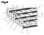
図6は、図5に示されたパネルエレメント1の実施変更形を示している。パネルエレメント1は2つのビーム41の他に、ボード2とビーム41とを貫通するピン47を有している。これらのピンは、パネルエレメント1に対して横方向に配列された対応する孔内に挿入されている。ピン47は木製ダボ又は木ねじとして形成されていてよいが、しかし他の材料、例えば金属又はプラスチックから成っていてもよい。パネルエレメント1の剛性が高められる他に、パネルエレメント1の幅10の方向に場合によっては生じる形状変化に関して、付加的な形状安定化がピン47によって達成される。ピン47のためには材料として木材が使用されることが好ましい。
FIG. 6 shows an implementation variant of the
図7は、図6に示されたパネルエレメント1の実施変更形を示している。この実施例によるボード2の場合、突起12内に溝48が成形されている。これらの溝48は平行に相並んで配置されており、ボード2の長手方向軸線に対して平行に延びている。溝48は、種々の層3,4,18の溝2間に閉じ込められた中空室を形成する。これにより、溝48の中空室内に閉じ込められた空気は、やはりパネルエレメント1の断熱作用を高める。
FIG. 7 shows a modified embodiment of the
しかし、ボード2の長手方向軸線5に対して平行に向けられた、突起12内の溝48とは別に、別の方向に向けられた溝、又は全く別の形状に成形された凹部が、閉じ込められた中空室をパネルエレメント1内に形成するために設けられていてもよい。しかし他方において、間に位置する中空室を形成するために、切り欠き11の領域内でボード2の材料にさらなる凹部が設けられていることも可能である。
However, apart from the
図8は図6に示されたパネルエレメント1を、横方向に位置するビーム41とともに示している。このために、ボード2の両端部領域には、図6に関連して説明したようにビーム41が配置されている。これらのビームは形状結合の他に、さらに付加的にピン47によってもパネルエレメント1と相対位置において固定されている。この実施例によれば、パネルエレメント1はボード2の両端部領域内のビーム41の他に、両端部領域から所定の距離を置いた中間領域内にもビーム49をさらに含んでいる。これらのビーム49はパネルエレメント1の層3,4,18の間に挿入されている。これらのビーム49はボード2の端部領域のビーム41と同様に、ボード2の長手方向軸線5に対して横方向にパネルエレメント1内に組み付けられている。ビーム49は実質的に方形断面を有しており、そしてボード2の層3,4,18の間にこれらを挿入するために、ボード2の隣接表面に、それも実施例によれば切り欠き11の領域内に、ビーム49の外形に対して相補的な付加的な切り欠きが設けられている。ボード2の端部領域のビーム49と同様に、ビーム49も付加的にピン47で固定されている。
FIG. 8 shows the
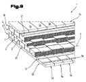
図9は、付加的な木製被覆体55を備えたパネルエレメント1の別の実施例を示している。このようなパネルエレメント1はその内部に、図3において記載されているような形式で、ボード2から成る3つの層3,4,18によって形成される。ボード2は互いに形状結合されている。両方の外面には、それぞれ木製被覆体55がボード56のさらなる層として配置されており、やはり第1層3及び第3層18と形状結合の形式で結合されている。このために、木製被覆体55のボード56は横方向に、すなわちボード2の長手方向延在長さもしくは長手方向軸線5に対して垂直に向けられて、平行に相並んで配置されている。木製被覆体55のボード56と、第1層3もしくは第3層18のボード2との結合は、複数の結合エレメント57を介在させることによって行われる。この実施例によれば、結合エレメント57は鳩尾レール(Gratleiste)によって形成されている。これらの鳩尾レール57はボード2の長手方向延在長さもしくは長手方向軸線5に対して平行に、ボード2内に設けられた対応する切り欠き内に挿入されている。木製被覆体55のボード56も同様に、対応する切り欠きもしくは溝58を有している。これらの切り欠きもしくは溝58によって、ボード56は結合エレメント57と結合することができる。既に説明したように、結合エレメント57は鳩尾レールによって形成されている。すなわち、一方ではボード56と結合エレメント57との間に、そして他方では結合エレメント57とボード2との間に、それぞれ鳩尾形継手の形式の形状結合が形成されている。
FIG. 9 shows another embodiment of the
しかし別の実施変更形では、結合エレメント57は雇い実矧ぎ(Nut-Feder-Verbindung)の形式に従って、一方ではボード2と、他方では木製被覆体55のボード56と結合されていてもよい。すなわち、結合エレメント57はいわゆる雇い実(Feder)によって形成され、木製被覆材55は、摩擦力結合によってボード2に固定されている。
However, in another implementation variant, the
図10は、図8に示されたパネルエレメント1の実施例を、別の実施変更形の木製被覆体55を有する状態で示す図である。木製被覆体55のボード56は平行に互いに相並んで、木製ダボ59又は木ねじの形態を成す結合エレメント57によって、パネルエレメント1のそれぞれ外側の層3,18と結合されている。木製ダボ59又は木ねじを使用することによって、摩擦力結合が達成される。
FIG. 10 is a view showing the embodiment of the
図11は、二層の木材被覆体55を備えたパネルエレメント1を示している。ボード56の第1層60は木製ダボ59によってパネルエレメント1のそれぞれ外側の層3,18に固定されている。他方において、第1層60のボード56は、鳩尾形の切り欠き及び突起を有している。これらの切り欠き及び突起は木製被覆体55の第2層61のボード56の対応する形状結合を可能にする。第1層61のボード56と第2層61のボード56との鳩尾形継手は、図1〜4に基づいて前述したような層3,4,18のボード2間の鳩尾形継手と同様に形成されている。
FIG. 11 shows a
図12及び13に基づいて、複数の層から組み立てられたビーム80について説明する。ビーム80はこの実施例によれば、3つのボードによって形成される。これらのボードは長手方向に平行に向けられて互いに接触し、そして互いに形状結合されている。このために、一方では第1ボード81と第2ボード82との間に、他方では第2ボード82と第3ボード83との間に、鳩尾形継手の形式の結合が形成されている。ボード81,82,83はそれぞれ長手方向延在長さの方向に連続して、鳩尾形の切り欠き84と突起85とから成る列を有している。切り欠き84及び突起85はボード81,82,83の幅86の方向に延びている。
A
図13は、ビーム80のボード81,82,83を、接合されていない状態で示している。図面から判るように、幅86の方向で見た切り欠き84もしくは突起85の断面は幅86全体にわたって可変である。しかも突起85の断面は第1縁部87から、対向する第2縁部88へ向かって楔状に可変に形成されている。鳩尾形継手の突起85は両側で、0.5°〜10°、有利には3°〜10°の値の半楔角だけ傾斜位置を有していることが好ましい。従って、一方では第1ボード81の突起85、他方では第2ボード82の切り欠き84は互いに相補的に形成されており、空間を埋めるように互いに接合することができる。ボード81,82,83を結合してビーム80にすることは、突起85の側面もしくは切り欠き84の側面の上記傾斜位置によって著しく容易になる。側面の傾斜位置に基づいて得られた、切り欠き84及び突起85の楔形状はさらに、接合時に相応に力を加えることによりある程度まで切り欠き84と突起85とを互いに押し嵌めることができ、こうしてボード81,82,83の結合を形成する際に付加的に摩擦力結合の効果を達成することもできる。
FIG. 13 shows the
しかし別の実施形態では、突起85もしくは切り欠き84の一方の側面だけに、側面の傾斜位置を設けることも可能である。別の実施変更形によれば、層から組み立てられた1つのビーム80が2つのボード81,82だけから組み立てられていてもよく、或いは、3つ(81,82,83)よりも多いボードによって形成されていてもよい。
However, in another embodiment, it is also possible to provide the inclined position of the side surface only on one side surface of the
これらの模範的実施態様は、パネルエレメント1の可能な実施変更形を示す。ここで念のため述べておくと、本発明は具体的に示された実施変更形に限定されることはなく、むしろ個々の実施変更形の種々の組み合わせも可能であり、そしてこのような変更は、この技術分野の当業者の能力範囲内で、技術的行為のための教示内容に基づいて可能である。つまり、上記実施変更形の個々の詳細を組み合わせることにより可能になる、考えられ得る全体的な実施変更形も、権利範囲に含まれる。
These exemplary embodiments show possible implementation variants of the
なお最後に形式的なことであるが、パネルエレメント1の構造をより良く理解するために、このエレメントもしくはその構成部分は部分的に一定の尺度でなく、且つ/又は拡大し、且つ/又は縮小して示した。
Finally, as a formal matter, in order to better understand the structure of the
本発明の独立した解決手段の根底を成す課題は、明細書から明らかである。 The problem underlying the independent solution of the present invention is clear from the description.
とりわけ図1;2;3,4;5,6;7;8;9;10;11;12及び13に示された個々の実施態様は、本発明による独立した解決手段の対象を形成することができる。これに関する本発明による課題及び解決手段は、これらの図面の詳細な説明から明らかである。 In particular, the individual embodiments shown in FIGS. 1; 2; 3,4; 5,6; 7; 8; 9; 10; 11; 12 and 13 form the subject of independent solutions according to the invention. Can do. The problem and solution according to the invention in this regard will become apparent from the detailed description of these drawings.
1 パネルエレメント
2 ボード
3 層
4 層
5 長手方向軸線
6 ボード
7 長手方向軸線
8 ボード
9 オーバーラップ幅
10 幅
11 切り欠き
12 突起
13 縁部
14 ボード中央
15 半楔角
16 ギャップ
17 中央平面
18 層
19 厚さ
20 溝
21 溝
22 間隔
23 内法幅
24 幅
25 領域
26 領域
27 厚さ
28 深さ
41 ビーム
42 厚さ
43 幅
44 切り欠き
45 深さ
46 側面
47 ピン
48 溝
49 ビーム
55 木製被覆体
56 ボード
57 結合エレメント
58 溝
59 木製ドエル
60 層
61 層
80 ビーム
81 ボード
82 ボード
83 ボード
84 切り欠き
85 突起
86 幅
87 ボード縁部
88 ボード縁部
89 楔角
DESCRIPTION OF
Claims (15)
第1層(3)のボード(2)が第2層(4)のボード(2)に対して平行に向けられており、第1層(3)のボード(2)と第2層(4)のボード(2)とが鳩尾形継手によって互いに結合されており、鳩尾形継手が、ボード(2)の長手方向延在長さの方向に連続する、鳩尾形の切り欠き(11)と突起(12)とから成る、ボード(2)内に成形された列によって形成されており、切り欠き(11)及び突起(12)はボード(2)の幅(10)の方向に延びている形式のパネルエレメント(1)において、
前記1層(3)のボード(2)と前記第2層(4)のボード(2)とが前記幅(10)の方向に互いに位置ずれし且つ互いにオーバーラップして配置されており、前記鳩尾形継手の切り欠き(11)がボード縁部(13)からボード中央(14)へ向かって楔状にテーパした状態で形成されていることを特徴とする、パネルエレメント(1)。 A wooden panel element (1) consisting of at least two layers (3, 4), each formed from boards (2) arranged side by side in parallel,
The board (2) of the first layer (3) is oriented parallel to the board (2) of the second layer (4), the board (2) of the first layer (3) and the second layer (4) ) And the board (2) are connected to each other by a pigeon tail joint, and the pigeon tail joint is continuous in the direction of the longitudinally extending length of the board (2). (12) formed by a row formed in the board (2), the notches (11) and the protrusions (12) extending in the direction of the width (10) of the board (2). Panel element (1)
The board (2) of the first layer (3) and the board (2) of the second layer (4) are arranged so as to be displaced from each other in the direction of the width (10) and overlap each other, Panel element (1), characterized in that the notch (11) of the pigtail joint is formed in a wedge-like state from the board edge (13) toward the board center (14).
前記鳩尾形継手の切り欠き(84)が第1ボード縁部(87)から第2ボード縁部(88)へ向かって楔状に延びた状態で形成されている
ことを特徴とする、ビーム(80)。 A wooden beam (80) composed of at least two boards (81, 82, 83) arranged in parallel contact with each other, wherein the first board (81) and the second board (82) are pigtail joints. The dovetail joint is composed of a dovetail notch (84) and a protrusion (85) which are continuous in the direction of the longitudinally extending length of the board (81, 82, 83). The notches (84) and the protrusions (85) are formed in the longitudinal direction of the board (81, 82, 83). In the form extending in the direction of a width (86) perpendicular to
The beam (80) characterized in that the notch (84) of the dovetail joint is formed in a wedge shape extending from the first board edge (87) toward the second board edge (88). ).
Applications Claiming Priority (3)
| Application Number | Priority Date | Filing Date | Title |
|---|---|---|---|
| EP13174730.5A EP2821191B1 (en) | 2013-07-02 | 2013-07-02 | Wooden panel element |
| EP13174730.5 | 2013-07-02 | ||
| PCT/EP2014/063288 WO2015000747A2 (en) | 2013-07-02 | 2014-06-24 | Panel element made of wood |
Publications (2)
| Publication Number | Publication Date |
|---|---|
| JP2016527418A JP2016527418A (en) | 2016-09-08 |
| JP6337106B2 true JP6337106B2 (en) | 2018-06-06 |
Family
ID=48703264
Family Applications (1)
| Application Number | Title | Priority Date | Filing Date |
|---|---|---|---|
| JP2016522446A Expired - Fee Related JP6337106B2 (en) | 2013-07-02 | 2014-06-24 | Wooden panel element |
Country Status (6)
| Country | Link |
|---|---|
| US (1) | US20160332411A1 (en) |
| EP (1) | EP2821191B1 (en) |
| JP (1) | JP6337106B2 (en) |
| CA (1) | CA2917090A1 (en) |
| PL (1) | PL2821191T3 (en) |
| WO (1) | WO2015000747A2 (en) |
Families Citing this family (13)
| Publication number | Priority date | Publication date | Assignee | Title |
|---|---|---|---|---|
| AT518854B1 (en) * | 2016-06-27 | 2019-11-15 | Schmidt Michael | Fin component |
| FR3056997B1 (en) * | 2016-10-03 | 2021-09-17 | Leko France | CONSTRUCTIVE SYSTEM WITH CROSSED STRUCTURAL BLADES |
| JP6857383B2 (en) * | 2016-11-21 | 2021-04-14 | 株式会社サカワ | Orthogonal laminated board |
| FI11685U1 (en) * | 2017-02-27 | 2017-06-09 | Aalto Haitek Oy | Liittopuujärjestely |
| DE102017115893A1 (en) * | 2017-07-14 | 2019-01-17 | Raimund Beck Nageltechnik Gmbh | composite component |
| US10858818B2 (en) * | 2017-07-18 | 2020-12-08 | Kurt Evan Haberman | Interlocking building system using one-piece skin-and-frame panels, vacuum-insulation, vertical slide-locks, multi-story slides, and snap-locks |
| AT520388B1 (en) | 2017-09-04 | 2019-06-15 | Hansmann Reinhard | Board for a composite element |
| EP3735390A2 (en) | 2018-01-05 | 2020-11-11 | Coravin, Inc. | Beverage dispenser and container stopper |
| EP3814584A4 (en) * | 2018-06-12 | 2022-07-27 | Intelligent City Inc. | Panel system for modular building construction |
| US20200149276A1 (en) * | 2018-11-13 | 2020-05-14 | Katerra Inc. | Cross laminated timber wall panel system |
| US11572691B1 (en) * | 2019-10-25 | 2023-02-07 | Newton Design, LLC | Modular wall system |
| AT524103B1 (en) * | 2020-07-24 | 2022-12-15 | Schmidt Michael | element for a compound element |
| AT524491A1 (en) * | 2020-12-14 | 2022-06-15 | Leitinger Hans Peter | Pair of boards, composite wood panel and method for their manufacture |
Family Cites Families (14)
| Publication number | Priority date | Publication date | Assignee | Title |
|---|---|---|---|---|
| BE503355A (en) | ||||
| US2104307A (en) * | 1935-11-04 | 1938-01-04 | Theodore H Miller | Method of forming end grain flooring |
| JPS6426422U (en) * | 1987-03-24 | 1989-02-15 | ||
| CA2187139C (en) * | 1996-10-04 | 2003-06-17 | John Di Poce | Wood article and method of manufacture |
| US6357194B1 (en) * | 1999-03-11 | 2002-03-19 | Archie Valejo Jones, Jr. | Tapered dovetail joint |
| JP2003285303A (en) * | 2002-01-22 | 2003-10-07 | Yutaka Ogino | Method for curving material, and material therefor |
| CA2371152A1 (en) * | 2002-02-06 | 2003-08-06 | Guildo Deschenes | Panels made of wood pieces edge-fitted one into another |
| AU2003901351A0 (en) * | 2003-03-24 | 2003-04-03 | Judi Collier | Composite building block having moisture barrier and insulation element |
| JP4070789B2 (en) * | 2003-12-24 | 2008-04-02 | 信吉 高橋 | Solid wood composite panel and narrow board used for this panel |
| WO2010020829A1 (en) * | 2005-01-20 | 2010-02-25 | Riviere Jim | Assembly of solid elements |
| ITBZ20050031A1 (en) | 2005-06-17 | 2006-12-18 | Reinverbund S R L | WALL ELEMENT FOR BUILDING AND COMPOSITE WOOD LAYER PANEL |
| GB2448545A (en) * | 2007-04-20 | 2008-10-22 | Moshe Lew | A floor panel |
| ITBZ20070046A1 (en) | 2007-11-19 | 2009-05-20 | Reinverbund Gmbh Srl | "GEBAUDEWANDELEMENT" |
| US8915039B1 (en) * | 2013-06-05 | 2014-12-23 | Vasile C. OROS | Solid-wood rigid block assemblies |
-
2013
- 2013-07-02 EP EP13174730.5A patent/EP2821191B1/en not_active Not-in-force
- 2013-07-02 PL PL13174730T patent/PL2821191T3/en unknown
-
2014
- 2014-06-24 WO PCT/EP2014/063288 patent/WO2015000747A2/en active Application Filing
- 2014-06-24 JP JP2016522446A patent/JP6337106B2/en not_active Expired - Fee Related
- 2014-06-24 CA CA2917090A patent/CA2917090A1/en not_active Abandoned
- 2014-06-24 US US14/902,090 patent/US20160332411A1/en not_active Abandoned
Also Published As
| Publication number | Publication date |
|---|---|
| WO2015000747A3 (en) | 2015-03-19 |
| WO2015000747A2 (en) | 2015-01-08 |
| PL2821191T3 (en) | 2016-03-31 |
| CA2917090A1 (en) | 2015-01-08 |
| JP2016527418A (en) | 2016-09-08 |
| US20160332411A1 (en) | 2016-11-17 |
| EP2821191B1 (en) | 2015-09-02 |
| EP2821191A1 (en) | 2015-01-07 |
Similar Documents
| Publication | Publication Date | Title |
|---|---|---|
| JP6337106B2 (en) | Wooden panel element | |
| EP2316624A2 (en) | Multi-layer wood panel | |
| KR20080106591A (en) | Wooden lattice beam for construction | |
| JP4857034B2 (en) | Composite wood structure material and method for producing composite wood structure material | |
| JP2016516925A (en) | Architectural element consisting of two panels containing bonding strips | |
| PL228156B1 (en) | Method for producing wooden core layer for floor or furniture panels | |
| US20070251174A1 (en) | Wood door | |
| EP3480385A2 (en) | A novel insulated cross-laminated construction element and method for using the same | |
| EP2937484A1 (en) | Corner joint | |
| JP2005053195A (en) | Method for producing composite woody structural material and joining method | |
| RU165765U1 (en) | CORNER ASSEMBLY | |
| RU175359U1 (en) | Wood element | |
| JP6857383B2 (en) | Orthogonal laminated board | |
| JP6048930B2 (en) | Joinery panel | |
| RU2417288C1 (en) | Device to erect wall panels | |
| JP7370217B2 (en) | frame door | |
| JP6319910B2 (en) | Wooden frame structure | |
| JP2018094783A (en) | Structural laminated wood | |
| JP6414261B2 (en) | Wood ramen moment resistance structure | |
| RU73894U1 (en) | WARMED BAR | |
| JP7071249B2 (en) | Joint structure of structural materials | |
| JP3361474B2 (en) | Building construction elements | |
| JP4516848B2 (en) | Composite wood structure material and method for producing composite wood structure material | |
| JP7308136B2 (en) | Fireproof wooden structural material | |
| RU14594U1 (en) | GLUED WOODEN ELEMENT |
Legal Events
| Date | Code | Title | Description |
|---|---|---|---|
| A621 | Written request for application examination |
Free format text: JAPANESE INTERMEDIATE CODE: A621 Effective date: 20170424 |
|
| A977 | Report on retrieval |
Free format text: JAPANESE INTERMEDIATE CODE: A971007 Effective date: 20180214 |
|
| TRDD | Decision of grant or rejection written | ||
| A01 | Written decision to grant a patent or to grant a registration (utility model) |
Free format text: JAPANESE INTERMEDIATE CODE: A01 Effective date: 20180403 |
|
| A61 | First payment of annual fees (during grant procedure) |
Free format text: JAPANESE INTERMEDIATE CODE: A61 Effective date: 20180507 |
|
| R150 | Certificate of patent or registration of utility model |
Ref document number: 6337106 Country of ref document: JP Free format text: JAPANESE INTERMEDIATE CODE: R150 |
|
| LAPS | Cancellation because of no payment of annual fees |