JP6334538B2 - Feeder part type determination method and feeder part type determination apparatus - Google Patents
Feeder part type determination method and feeder part type determination apparatus Download PDFInfo
- Publication number
- JP6334538B2 JP6334538B2 JP2015532618A JP2015532618A JP6334538B2 JP 6334538 B2 JP6334538 B2 JP 6334538B2 JP 2015532618 A JP2015532618 A JP 2015532618A JP 2015532618 A JP2015532618 A JP 2015532618A JP 6334538 B2 JP6334538 B2 JP 6334538B2
- Authority
- JP
- Japan
- Prior art keywords
- component
- tape
- feeder
- accuracy
- type
- Prior art date
- Legal status (The legal status is an assumption and is not a legal conclusion. Google has not performed a legal analysis and makes no representation as to the accuracy of the status listed.)
- Active
Links
Images


Classifications
-
- H—ELECTRICITY
- H05—ELECTRIC TECHNIQUES NOT OTHERWISE PROVIDED FOR
- H05K—PRINTED CIRCUITS; CASINGS OR CONSTRUCTIONAL DETAILS OF ELECTRIC APPARATUS; MANUFACTURE OF ASSEMBLAGES OF ELECTRICAL COMPONENTS
- H05K13/00—Apparatus or processes specially adapted for manufacturing or adjusting assemblages of electric components
- H05K13/08—Monitoring manufacture of assemblages
-
- H—ELECTRICITY
- H05—ELECTRIC TECHNIQUES NOT OTHERWISE PROVIDED FOR
- H05K—PRINTED CIRCUITS; CASINGS OR CONSTRUCTIONAL DETAILS OF ELECTRIC APPARATUS; MANUFACTURE OF ASSEMBLAGES OF ELECTRICAL COMPONENTS
- H05K13/00—Apparatus or processes specially adapted for manufacturing or adjusting assemblages of electric components
- H05K13/04—Mounting of components, e.g. of leadless components
- H05K13/0417—Feeding with belts or tapes
-
- H—ELECTRICITY
- H05—ELECTRIC TECHNIQUES NOT OTHERWISE PROVIDED FOR
- H05K—PRINTED CIRCUITS; CASINGS OR CONSTRUCTIONAL DETAILS OF ELECTRIC APPARATUS; MANUFACTURE OF ASSEMBLAGES OF ELECTRICAL COMPONENTS
- H05K13/00—Apparatus or processes specially adapted for manufacturing or adjusting assemblages of electric components
- H05K13/08—Monitoring manufacture of assemblages
- H05K13/089—Calibration, teaching or correction of mechanical systems, e.g. of the mounting head
Description
本発明は、部品実装機の部品供給装置を構成するテープフィーダに関し、より詳細には、複数のテープフィーダと、それらに装填するキャリアテープに収納された部品の複数の部品種との組合せを決定する方法、および組合せを決定する装置に関する。 The present invention relates to a tape feeder constituting a component supply device of a component mounting machine, and more specifically, a combination of a plurality of tape feeders and a plurality of component types of components housed in a carrier tape to be loaded thereon is determined. And a device for determining a combination.
多数の部品が実装されたプリント基板を生産する機器として、半田印刷機、部品実装機、リフロー炉、基板検査機などがあり、これらを連結して基板生産ラインを構築する場合が多い。このうち部品実装機は、基板搬送装置、部品供給装置、および部品移載装置を備えるのが一般的である。基板搬送装置は、プリント基板の搬入出および位置決めを行う。部品供給装置は、複数の部品種の部品を所定の供給位置に順次供給する。部品供給装置の代表例としてフィーダ式部品供給装置がある。フィーダ式部品供給装置は、複数のテープフィーダを着脱可能に装備するのが一般的である。各テープフィーダは、複数の部品を等ピッチで収納したキャリアテープを保持して、順次部品を供給位置に供給する。部品移載装置は、負圧を利用して部品供給装置の供給位置から部品を吸着し、位置決めされたプリント基板に装着する。 As a device for producing a printed circuit board on which a large number of components are mounted, there are a solder printing machine, a component mounting machine, a reflow furnace, a board inspection machine, and the like, and these are often connected to construct a board production line. Of these, the component mounting machine generally includes a substrate transfer device, a component supply device, and a component transfer device. The board transport device carries in and out the printed board and positions it. The component supply apparatus sequentially supplies components of a plurality of component types to a predetermined supply position. A typical example of the component supply device is a feeder-type component supply device. In general, the feeder-type component supply device is detachably equipped with a plurality of tape feeders. Each tape feeder holds a carrier tape containing a plurality of parts at an equal pitch, and sequentially supplies the parts to a supply position. The component transfer device sucks a component from the supply position of the component supply device using negative pressure and mounts the component on the printed circuit board.
上記したフィーダ式部品供給装置に関して、キャリアテープの幅寸法や部品間のピッチ寸法などの仕様は、部品の大きさなどに基づいてJIS規格などで段階的に定められている。テープフィーダがキャリアテープを間欠送給する送給量は、理想的にはピッチ寸法に一致することが好ましいが、毎回厳密に一致するとは限らず、変動し得る。送給量の変動は、実際に部品を受け渡す供給位置の位置精度に直結している。テープフィーダの供給位置の位置精度は、一般的に、部品移載装置の吸着ノズルが安定して部品を吸着できるように管理されている。 With respect to the feeder-type component supply device described above, specifications such as the width dimension of the carrier tape and the pitch dimension between the components are determined in stages in accordance with the JIS standard and the like based on the size of the component. The feed amount that the tape feeder intermittently feeds the carrier tape ideally matches the pitch dimension, but it does not always match exactly and may vary. The fluctuation of the feed amount is directly related to the position accuracy of the supply position where the parts are actually delivered. The position accuracy of the supply position of the tape feeder is generally managed so that the suction nozzle of the component transfer device can stably suction the component.
しかしながら、テープフィーダの位置精度は、同じ仕様のキャリアテープを用いる同一種のテープフィーダであっても個体差が避けられない。加えて、長年の稼動による駆動部の摩耗などで、位置精度が経時低下することも考えられる。位置精度の低下は、吸着ノズルが部品を吸着できない吸着ミスにつながる。吸着ミスにより、部品の浪費やリカバリー動作による生産効率の低下などが発生する。さらに、位置精度の低下したテープフィーダが混在することで段取り作業などの作業性が低下し、生産効率が一層低下する。 However, the position accuracy of the tape feeder cannot be avoided even if the tape feeder of the same type using the same type of carrier tape is used. In addition, it is conceivable that the position accuracy is deteriorated with time due to wear of the drive unit due to operation for many years. A decrease in position accuracy leads to a suction error in which the suction nozzle cannot suck the component. Mistakes in suction cause parts to be wasted and production efficiency is reduced due to recovery operations. Further, the mixing of tape feeders with reduced positional accuracy reduces workability such as setup work, and further reduces production efficiency.
本願出願人は、このようなテープフィーダの位置精度の低下に対応するメンテナンス方法を特許文献1に開示している。特許文献1の電子回路部品実装機のメンテナンス方法は、複数の工場に設置された複数台の電子回路部品実装機の構成要素のメンテナンスを集中的に行う。そして、構成要素に部品フィーダ(テープフィーダ)を含み、例えば、1つの監視システムにより複数台の電子回路部品実装機をリアルタイムで集中して監視する。これにより、頻繁に作動して劣化や消耗が激しく、したがってメンテナンスが必要になりやすく、かつ種類や数量の多い部品フィーダのメンテナンスを集中的に行える。また、電子回路部品実装機の稼動率の低下を回避するために予備の部品フィーダが必要であるが、予備保有数を減らすことができる。 The applicant of the present application discloses a maintenance method corresponding to such a decrease in positional accuracy of the tape feeder in Patent Document 1. The maintenance method of the electronic circuit component mounting machine of patent document 1 performs the maintenance of the component of the several electronic circuit component mounting machine installed in the some factory intensively. The component includes a component feeder (tape feeder). For example, a single monitoring system centrally monitors a plurality of electronic circuit component mounting machines in real time. As a result, it is frequently operated and is severely deteriorated and consumed. Therefore, maintenance is easily required, and maintenance of a component feeder having a large number of types and quantities can be performed intensively. In addition, a spare parts feeder is necessary to avoid a decrease in the operating rate of the electronic circuit component mounting machine, but the number of spare parts can be reduced.
ところで、最近では、スマートフォンに代表されるように電子回路の小形高機能化が進み、使用される部品が極小化されつつある。例えば、チップ抵抗器やチップコンデンサなどのチップ部品では、部品外形寸法が0.2×0.1(mm)や0.3×0.15(mm)、0.4×0.2(mm)などの極小部品が使用されるようになってきている。このような極小部品を供給するテープフィーダでは、供給位置の精度管理を従来よりも厳密に行わないと、吸着ミスが頻繁に発生することが懸念される。このため、特許文献1に例示される従来のメンテナンス技術では不十分であり、個々のテープフィーダの位置精度の個体差や経年低下などの影響を考慮して、装填するキャリアテープの部品種との組合せを決定することが好ましいと考えられる。 Recently, as represented by smartphones, electronic circuits are becoming smaller and more functional, and the components used are being minimized. For example, in chip parts such as chip resistors and chip capacitors, the external dimensions of the parts are 0.2 × 0.1 (mm), 0.3 × 0.15 (mm), 0.4 × 0.2 (mm). Minimal parts such as are now being used. In such a tape feeder that supplies extremely small components, there is a concern that suction mistakes frequently occur unless the accuracy management of the supply position is performed more strictly than in the past. For this reason, the conventional maintenance technique exemplified in Patent Document 1 is not sufficient, and considering the effects of individual differences in position accuracy of individual tape feeders and deterioration over time, the type of carrier tape to be loaded It may be preferable to determine the combination.
本発明は、上記背景技術の問題点に鑑みてなされたものであり、極小部品などを供給する複数のテープフィーダの供給位置の位置精度の個体差や経年低下などの影響を考慮して、装填するキャリアテープに収納された部品の部品種との組合せを決定することで部品の吸着動作が安定し、プリント基板の生産効率を高められるフィーダ部品種決定方法およびフィーダ部品種決定装置を提供することを解決すべき課題とする。 The present invention has been made in view of the above-mentioned problems of the background art, and is loaded in consideration of individual differences in position accuracy of a plurality of tape feeders that supply extremely small parts and the like, and effects such as aging. To provide a feeder component type determination method and a feeder component type determination device that can stabilize the adsorption operation of the components by determining the combination with the component types of the components stored in the carrier tape to be used, and increase the production efficiency of the printed circuit board. Is a problem to be solved.
上記課題を解決する本発明のフィーダ部品種決定方法は、複数の部品を等ピッチで収納したキャリアテープをそれぞれ保持して前記部品をそれぞれの供給位置に順次供給する複数のテープフィーダを着脱可能に装備する部品供給装置と、前記供給位置に供給された前記部品を吸着して装着実施位置に位置決めされたプリント基板に装着する部品移載装置とを備えた部品実装機で、複数の前記テープフィーダと前記キャリアテープに収納された前記部品の複数の部品種との組合せを決定するフィーダ部品種決定方法であって、前記テープフィーダの少なくとも一部である複数の前記テープフィーダの各々について、前記供給位置での位置精度を測定する位置精度測定ステップと、前記位置精度を測定された前記テープフィーダの各々の前記位置精度と、前記部品の前記部品種によって定まる部品外形寸法および当該の前記部品が前記テープフィーダによって前記供給位置に供給されたときの許容位置精度の少なくとも一方とに基づいて、前記位置精度を測定され、かつ前記プリント基板に装着する前記部品を供給するために使用される前記テープフィーダの各々と前記キャリアテープに収納された前記部品の前記部品種との組合せを決定する部品種決定ステップと、を有し、前記部品種決定ステップで、前記テープフィーダの前記位置精度が高いほど前記部品外形寸法が小さい前記部品種と組み合わせ、前記テープフィーダの前記位置精度が低いほど前記部品外形寸法が大きい前記部品種と組み合わせる。 The feeder component type determination method of the present invention that solves the above-described problem makes it possible to attach and detach a plurality of tape feeders that respectively hold carrier tapes that store a plurality of components at an equal pitch and sequentially supply the components to respective supply positions. A component mounting machine comprising: a component supply device to be equipped; and a component transfer device that sucks the component supplied to the supply position and mounts the component on a printed circuit board positioned at the mounting position. And a feeder part type determination method for determining a combination of a plurality of part types of the parts stored in the carrier tape, wherein each of the plurality of tape feeders that are at least part of the tape feeder is supplied A position accuracy measuring step for measuring the position accuracy at the position; and the position of each of the tape feeders for which the position accuracy has been measured. And degrees, based on at least one of the acceptable positional accuracy when supplied to the supply position the component parts Dimensions and the determined by the component type of the component by the tape feeder is measured the position accuracy And a component type determining step for determining a combination of each of the tape feeders used for supplying the components to be mounted on the printed circuit board and the component types of the components stored in the carrier tape, Yes, and by the component type decision step, wherein the higher the positional accuracy of the tape feeder part outer dimensions smaller the component type and combination, wherein the component dimensions the lower the positional accuracy of the tape feeder is large the portion Combine with varieties.
本発明のフィーダ部品種決定方法では、位置精度測定ステップで、テープフィーダの少なくとも一部について、供給位置での位置精度を測定するので、位置精度の個体差や経年低下などの影響を個別にかつ正確に把握できる。そして、部品種決定ステップで、テープフィーダの位置精度と、部品の部品種によって定まる部品外形寸法および許容位置精度の少なくとも一方とに基づいて、テープフィーダとキャリアテープに収納された部品の部品種との組合せを決定する。さらに、テープフィーダの位置精度が高いほど部品外形寸法が小さい部品種と組み合わせ、テープフィーダの位置精度が低いほど部品外形寸法が大きい部品種と組み合わせる。したがって、許容位置精度の厳しい極小部品に対しても吸着ミスを抑制でき、プリント基板の生産効率を高められる。
In the feeder part type determination method of the present invention, in the position accuracy measurement step, the position accuracy at the supply position is measured for at least a part of the tape feeder. Accurately grasp. Then, in the component type determination step, based on the position accuracy of the tape feeder and at least one of the component external dimension and the allowable position accuracy determined by the component type of the component, the component type of the component stored in the tape feeder and the carrier tape The combination of is determined. Further, the higher the positional accuracy of the tape feeder, the smaller the component external dimension is combined with the smaller component type, and the lower the tape feeder positional accuracy, the larger the component external dimension is combined. Therefore, it is possible to suppress mistakes in suction even for extremely small parts with strict allowable position accuracy, and the production efficiency of the printed circuit board can be increased.
本発明の実施形態のフィーダ部品種決定方法について、図1〜図9を参考にして説明する。まず、実施形態のフィーダ部品種決定方法を行うことができる部品実装機1の構成例について説明する。図1は、実施形態のフィーダ部品種決定方法を行う部品実装機1の構成例を示す平面図である。部品実装機1は、基板搬送装置2、部品供給装置3、部品移載装置4、および図略の制御コンピュータなどが機台8に組み付けられて構成されている。図1の紙面上下方向がプリント基板Kを搬送するX軸方向であり、紙面左右方向すなわち部品実装機1の長手方向がY軸方向である。
A feeder component type determination method according to an embodiment of the present invention will be described with reference to FIGS. First, a configuration example of the component mounter 1 that can perform the feeder component type determination method of the embodiment will be described. FIG. 1 is a plan view illustrating a configuration example of a component mounter 1 that performs a feeder component type determination method according to an embodiment. The component mounter 1 is configured by assembling a
基板搬送装置2は、2枚のプリント基板Kを並行して搬送できるデュアルレーンタイプの装置である。基板搬送装置2は、並設された第1レーン21および第2レーン22でそれぞれ、プリント基板Kを装着実施位置に搬入し、位置決めし、搬出する。第1レーン21および第2レーン22はそれぞれ、一対のガイドレール23、24、一対のコンベアベルト、およびクランプ装置などで構成されている。一対のガイドレール23、24は、機台8の上部中央に組み付けられており、互いに平行してプリント基板Kの搬送方向(X軸方向)に延在している。一対のガイドレール23、24の間には、互いに平行に配置された図略の一対の無端環状のコンベアベルトが設けられている。一対のコンベアベルトは、コンベア搬送面にプリント基板Kを戴置した状態で輪転して、プリント基板Kを機台8の中央部に設定された装着実施位置に搬入および搬出する。
The
装着実施位置のコンベアベルトの下方には、図略のクランプ装置が設けられている。クランプ装置は、コンベアベルトからプリント基板Kを押し上げて水平姿勢でクランプし、装着実施位置に位置決めする。これにより、部品移載装置4が装着実施位置で装着動作を行えるようになる。図1では、第1レーン21にプリント基板Kが搬入されて装着実施位置に位置決めされ、第2レーン22にプリント基板Kが搬入されていない状況が例示されている。
A clamp device (not shown) is provided below the conveyor belt at the mounting position. The clamp device pushes up the printed circuit board K from the conveyor belt, clamps it in a horizontal posture, and positions it at the mounting position. As a result, the
部品供給装置3は、支持台31、8台のテープフィーダ32、および8台のリール保持部39で構成されており、最大で8部品種の部品Pを供給する。8台のテープフィーダ32は、以降の説明を簡明にするための例であって、実際には、8台よりも多数のテープフィーダ32を装備して、より多数の部品種を供給できる部品供給装置が一般的である。支持台31は、略矩形の部材であり、その幅方向寸法(X軸方向寸法)が機台8の幅寸法に概ね等しい。支持台31の上面には、長手方向(Y軸方向)に延在して幅方向(X軸方向)に並んだ8箇所のスロットが形成されている。支持台31は、機台8の後側の上面に着脱可能に装備される(図5参照)。
The
テープフィーダ32は、上下方向および前後方向に長く、幅方向が狭い扁平形状をしている。8台のテープフィーダ32は、支持台31の8箇所のスロットに後側から挿入されて装備され、X軸方向に列設されて用いられる。8台のリール保持部39はそれぞれ、組になる各テープフィーダ32の後側に装備されて用いられる。リール保持部39は、第1リール391および第2リール392を前後(Y軸方向)に並べて交換可能に保持している。第1リール391および第2リール392には、多数の部品Pを等ピッチLpで収納したキャリアテープ5が巻回されている。第1リール391および第2リール392の側面には、巻回されたキャリアテープ5が収納している部品Pの部品種や製造メーカなどを特定する部品種特定コードが付設されている。部品種特定コードとしてバーコードを例示でき、これに限定されない。なお、8台を超えるテープフィーダ32を予め準備しておいて、交換して用いることができる。
The
部品供給装置3の各テープフィーダ32は、第1リール391および第2リール392にそれぞれ巻回されたキャリアテープ5の先端を挿入口32Eから挿入して装填することができる。各テープフィーダ32は、一方のキャリアテープ5を所定のピッチLpずつ間欠送給することで、先端の供給位置32Sに部品Pを供給する。また、各テープフィーダ32は、一方のキャリアテープ5を使い切ると、他方のキャリアテープ5を自動で送給し始める。これにより、リール保持部39では、一方のキャリアテープ5を巻回していたリールを取り外して、第3のキャリアテープ5を巻回した第3リール(図略)を保持できるようになる。キャリアテープ5およびテープフィーダ32の詳細構造については後述する。
Each
部品移載装置4は、部品供給装置3のテープフィーダ32の供給位置32Sから部品を吸着し、装着実施位置に位置決めされたプリント基板Kまで搬送して装着する。部品移載装置4は、X軸方向およびY軸方向に水平移動可能なXYロボットタイプの装置である。部品移載装置4は、一対のY軸レール41、42、Y軸スライダ43、Y軸サーボモータ44、X軸スライダ45、図略のX軸サーボモータ、装着ヘッド46、および図略の吸着ノズルなどで構成されている。
The
一対のY軸レール41、42、Y軸スライダ43、およびY軸サーボモータ44などでY軸駆動ロボットが構成されている。一対のY軸レール41、42は、機台8の長手方向の前側から、位置決めされたプリント基板Kの上空を通り、後側の部品供給装置3の上方まで平行して配設されている。Y軸レール41、42上に、Y軸スライダ43が移動可能に装架されている。Y軸スライダ43は、Y軸サーボモータ44の出力軸に連結されたボールねじ441を含むボールねじ機構によって、Y軸方向に駆動される。
A pair of Y-
X軸スライダ45およびX軸サーボモータなどでX軸駆動ロボットが構成されている。X軸スライダ45は、Y軸スライダ43のX軸方向に延びる一側面に移動可能に装架されている。また、Y軸スライダ43上に、図略のX軸サーボモータが配設されている。X軸スライダ45は、X軸サーボモータの出力軸に連結されたボールねじを含むボールねじ機構によって、X軸方向に駆動される。
An X-axis drive robot is constituted by the
X軸スライダ45の側面には、装着ヘッド46が交換可能に配設されている。装着ヘッド46の下側には、図には見えない複数の吸着ノズルが着脱可能に保持されている。吸着ノズルは、X軸駆動ロボットおよびY軸駆動ロボットによりテープフィーダ32の供給位置32Sまで駆動されると、負圧を利用して供給位置32Sの部品Pを吸着する。次に、吸着ノズルは、X軸駆動ロボットおよびY軸駆動ロボットにより位置決めされたプリント基板Kまで駆動されると、部品Pをプリント基板K上に装着する。
A mounting
図略の制御コンピュータは、プリント基板Kの生産動作を制御し、プリント基板Kの生産状況を管理する。具体的に、制御コンピュータは、基板搬送装置2によるプリント基板Kの搬送動作および位置決め動作を制御し、部品移載装置4による部品の吸着動作、搬送動作、および装着動作を制御する。また、制御コンピュータは、プリント基板Kの生産数を管理し、生産動作時に生じたエラーに対応する。制御コンピュータは、生産するプリント基板Kの種類と装着する部品Pの部品種との対応関係や、プリント基板K上の各部品Pの装着座標位置などの設計諸情報を予め取得している。また、制御コンピュータは、部品供給装置3の各テープフィーダ32から供給される部品Pの部品種の並び順や、プリント基板Kに装着する部品Pの装着順序、プリント基板Kの生産予定枚数や生産完了予定時刻などの生産諸情報も予め取得している。
A control computer (not shown) controls the production operation of the printed circuit board K and manages the production status of the printed circuit board K. Specifically, the control computer controls the transport operation and positioning operation of the printed circuit board K by the
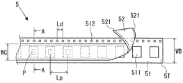
次に、キャリアテープ5の詳細構造について説明する。図2は、キャリアテープ5の先端部5Tに近い一部分を示す平面図である。また、図3は、図2のA−A矢視図であって、キャリアテープ5が部品Pを収納している状態を示す断面図である。図3に示されるように、キャリアテープ5は、ベーステープ51、カバーテープ52、およびボトムテープ53の三層構造からなる。ベーステープ51は、紙材や樹脂などの柔軟な材料で形成されており、幅寸法WBで細長く薄い帯状の部材である。ベーステープ51の幅方向の中央付近には、長さ方向に等ピッチLpで多数の矩形の収納凹部511が設けられている。また、ベーステープ51の一方の側縁寄りには、長さ方向に一定の間隔Ldで側縁に平行して多数の係合穴512が穿設されている。
Next, the detailed structure of the
ベーステープ51の表面には、カバーテープ52が剥離可能に貼設されている。カバーテープ52は、透明な高分子フィルムによって形成されており、幅寸法WCで細長く薄い帯状の部材である。カバーテープ52の幅寸法WCは、ベーステープの幅寸法WBよりも狭く、収納凹部511よりも広い。カバーテープ52の厚みは、ベーステープ51よりも薄い。カバーテープ52の両縁は、塗布された接着剤521によってベーステープ51の表面の係合穴512および収納凹部511を避けた範囲に接着されている。
A
一方、ベーステープ51の裏面には、図3に示されるように、ボトムテープ53が貼設されている。ボトムテープ53は、透明な高分子フィルムによって形成されており、幅寸法WBで細長く薄い帯状の部材である。ボトムテープ53の幅寸法WBは、ベーステープ51の幅寸法WBに略一致している。ボトムテープ53の厚みは、ベーステープ51よりも薄く、カバーテープ52と同程度である。ボトムテープ53は、塗布された接着剤によってベーステープ51の裏面の収納凹部511を避けた範囲に接着されている。そして、ベーステープ51の係合穴512に重なるように、ボトムテープ53にも係合穴531が穿設されている。
On the other hand, a
図2に示されるように、部品Pは、収納凹部511の略中央に収納される。なお、キャリアテープ5の先端部5Tおよび後端部から所定距離以内の収納凹部511、図2の例では先端51Tから5番目までの収納凹部511に部品Pは始めから収納されていない。また、図3に示されるように、収納凹部511はカバーテープ52およびボトムテープ53に上下を挟み込まれており、これによって部品Pが封止される。テープフィーダ32の供給位置32Sの付近で、図2に示されるように、ベーステープ51の先端部5Tからカバーテープ52が順次剥離されて、部品Pが供給される。
As shown in FIG. 2, the component P is housed in the approximate center of the
次に、テープフィーダ32の位置精度を測定する後述のフィーダ検査治具91で使用する測定用テープ6について説明する。図4は、テープフィーダ32の位置精度を測定する際にキャリアテープ5の代替として使用する測定用テープ6を示す平面図である。測定用テープ6は、熱膨張率が小さく、歪みや変形が発生しにくい金属製薄帯で形成されている。測定用テープ6の幅寸法WBは、キャリアテープ5のベーステープ51の幅寸法WBに等しい。測定用テープ6の幅方向の中央付近には、キャリアテープ5の収納凹部511と同一の等ピッチLpで多数の十字形の測定用マーカ61が刻設または描設されている。また、測定用テープ6の一方の側縁寄りに、キャリアテープ5の係合穴512、531と同一の間隔Ldで側縁に平行して多数の係合穴62が穿設されている。
Next, the measuring
ここで、キャリアテープ5では、収納凹部511が形成されるピッチLpは製造誤差を含み、さらに、ベーステープ51が温度変化や外力で伸縮するおそれもある。加えて、部品Pが収納凹部511の中央に正確に収納されているとは限らず、部品P間のピッチLpは誤差が大きくなりがちである。これに対して、測定用テープ6の測定用マーカ61のピッチLpは格段に精度が高い。したがって、キャリアテープ5に代えて測定用テープ6を用いることで、キャリアテープ5の送給量の再現精度、換言すれば、テープフィーダ32の供給位置32Sにおける位置精度を正確に測定できる。
Here, in the
次に、テープフィーダ32の詳細構造について説明する。図5は、テープフィーダ32の側面図であり、紙面手前側の側板が省略されて内部の詳細構造が示されている。テープフィーダ32は、フィーダ筺体33を形成する2枚の側板の間にレール34、テープ送給機構35、次使用テープ制御機構36、制御部37、および図略のテープ剥離機構などが組み付けられて構成されている。
Next, the detailed structure of the
フィーダ筺体33を形成する2枚の側板は、扁平形状の幅方向分だけ離隔平行して配置されている。フィーダ筺体33は支持台31よりも長く、フィーダ筺体33の大部分は支持台31の上面のスロット上に位置するが、フィーダ筺体33の後側の一部は支持台31の後側(図の左側)から下方にかけて位置する。フィーダ筺体33は、後側寄りの上部が矩形に切欠かれて、持ち運び用の取手33Bが形成されている。フィーダ筺体33の側面には、テープフィーダ32を特定するフィーダ特定コードが付設されている。フィーダ特定コードとしてバーコードを例示でき、これに限定されない。
The two side plates that form the
レール34は、その上面でキャリアテープ5の送給を案内する部材である。レール34は、フィーダ筺体33の内側で後端から前端まで延在する細長い板状の部材であり、途中の2箇所で屈曲している。レール34は、後端から前側に向かって順番に、水平な第1レール部341、傾斜上向きの第2レール部342、および水平な第3レール部343からなる。第1レール部341の長さを基準として、第2レール部342は少し短く、第3レール部343は大幅に長い。第1レール部341の後端には挿入口32Eが形成されている。挿入口32Eは、2つのキャリアテープ5を上下に重ねて挿入でき、これによりキャリアテープ5を装填できるようになっている。第3レール部343の先端付近の上面が供給位置32Sに相当する。
The
供給位置32Sの近くに、図略のテープ剥離機構が配設されている。テープ剥離機構は、キャリアテープ5の間欠送給に同期して、ベーステープ51からカバーテープ52をピッチLp分ずつ剥離する。テープ剥離機構については、特許第2662948号公報、特開2009−140994号公報、および実公平7−23994号公報などに開示された公知技術を応用できるので、説明は省略する。
A tape peeling mechanism (not shown) is disposed near the
テープ送給機構35は、レール34の下側に配設されており、キャリアテープ5をレール34の上面に沿って供給位置32SへとピッチLp分ずつ間欠送給する。テープ送給機構35は、モータ351、第1ギヤ352、第2ギヤ353、第1スプロケット354、第3ギヤ355、および第2スプロケット356などで構成されている。
The
第3レール部343の下側の後側から前側に向かって順番に、モータ351、第1ギヤ352、第2ギヤ353、および第1スプロケット354が配設されている。モータ351の出力軸には、小径のドライブギヤ351Dが固設されている。第1ギヤ352は、回転自在に軸承されており、外周に従動ギヤ352Fを有し、内側に内側駆動ギヤ352Dを有している。従動ギヤ352Fは、モータ351の出力軸のドライブギヤ351Dと噛合している。第2ギヤ353は、回転自在に軸承されており、第1ギヤ352の内側駆動ギヤ352Dと噛合している。第1スプロケット354は、回転自在に軸承されており、外周に一定角度間隔で形成された係合突起354Kを有し、内側に内側従動ギヤ354Fを有している。内側従動ギヤ354Fは、第2ギヤ353と噛合している。係合突起354Kは、第3レール部343に穿設された侵入穴344から上方に突出し、キャリアテープ5の係合穴512、531や測定用テープ6の係合穴62に係入するようになっている。なお、係合突起354Kの侵入穴344からの突出量は、キャリアテープ5の厚さと同等か厚さ以上であることが好ましい。
A
さらに、第3レール部343の下側のモータ351よりも後側に、第3ギヤ355が配設されている。第3ギヤ355は、回転自在に軸承されており、外周に従動ギヤ355Fを有し、内側に内側駆動プーリー355Dを有している。従動ギヤ355Fは、モータ351の出力軸のドライブギヤ351Dと噛合している。一方、第1レール部341の下側に、第2スプロケット356が配設されている。第2スプロケット356は、回転自在に軸承されており、外周に一定角度間隔で形成された係合突起356Kを有し、少し内側に内側従動プーリー356Fを有している。係合突起356Kは、第1レール部341に穿設された侵入穴345から上方に突出し、キャリアテープ5の係合穴512、531や測定用テープ6の係合穴62に係入するようになっている。なお、係合突起356Kの侵入穴345からの突出量は、キャリアテープ5の厚さ以下に限定されている。
Further, a
第3ギヤ355の内側駆動プーリー355Dと、第2スプロケット356の内側従動プーリー356Fとの間に、ドライブベルト357が輪転するように巻き掛けられている。さらに、ドライブベルト357が輪転する往路および復路の途中に、それぞれテンションプーリー358、359が回転自在に設けられている。2個のテンションプーリー358、359は、ドライブベルト357を押圧してテンションを発生させ、ドライブベルト357の滑りを防止している。
A
上述したテープ送給機構35で、モータ351の出力軸がピッチLp相当分だけ反時計回りに回転すると、第1ギヤ352および第2ギヤ353を介して第1スプロケット354が時計回りに回転駆動されるとともに、第3ギヤ355およびドライブベルト357を介して第2スプロケット356が時計回りに回転駆動される。第1スプロケット354および第2スプロケット356は、ともに減速回転駆動されるが減速比は同一とされており、キャリアテープ5や測定用テープ6を同期してピッチLp分ずつ間欠送給できる。
When the output shaft of the
次使用テープ制御機構36は、第1レール部341の上側に配設されている。次使用テープ制御機構36は、現在使用している第1のキャリアテープ5の送給を許容し、次に使用する第2のキャリアテープ5の先端部5Tの保持および送給を制御する。次使用テープ制御機構36は、機構基部361、第1押圧部材362、第2押圧部材363、およびテープ端検出センサ364などで構成されている。
The next use
機構基部361は、前後方向に長いブロック状の部材であり、第1レール部341の上方に離隔平行して固設されている。機構基部361には、前後方向に所定距離dだけ離れて上下方向に貫通する一対のスライド穴361Hが2組穿設されており、換言すれば、合計で4個のスライド穴361Hが前後方向に並んで設けられている。
The
第1押圧部材362および第2押圧部材363は、前後方向の長さが機構基部361の半分弱のブロック状の部材である。第1押圧部材362および第2押圧部材363は、機構基部361と第1レール部341との間に、第1押圧部材362を前側にして配置されている。第1押圧部材362は、その上面の前後方向に所定距離dだけ離れて立設された2本のスライド軸362Aを有している。2本のスライド軸362Aは、機構基部361の前側2個のスライド穴361Hに上下動可能に係入している。さらに、2本のスライド軸362Aの周りにそれぞれ、コイルスプリング362Cが配設されている。コイルスプリング362Cは、上側の一端が機構基部361に当接して、下側の他端で第1押圧部材362を第1レール部341に向けて押圧している。
The first
同様に、第2押圧部材363は、その上面の前後方向に所定距離dだけ離れて立設された2本のスライド軸363Aを有している。2本のスライド軸363Aは、機構基部361の後側2個のスライド穴361Hに上下動可能に係入している。さらに、2本のスライド軸363Aの周りにそれぞれ、コイルスプリング363Cが配設されている。コイルスプリング363Cは、上側の一端が機構基部361に当接して、下側の他端で第2押圧部材363を第1レール部341に向けて押圧している。
Similarly, the second pressing
上述した構成により、第1押圧部材362および第2押圧部材363は、上下方向に独立して移動可能であり、かつ前後方向および幅方向には移動できないようになっている。そして、第2スプロケット356の係合突起356Kは、第1押圧部材362と第2押圧部材363との中間位置で最も高く突出するように配置されている。ここで、第2押圧部材363の底面は水平面であり、第1押圧部材362の底面には切欠き保持部362Kが形成されている。切欠き保持部362Kは、第1押圧部材362の底面の後側を切り欠いて形成され、その切欠き高さはキャリアテープ5の厚さよりも大きめとされている。
With the above-described configuration, the first pressing
段取り作業で、第1レール部341の後端の挿入口32Eから第1のキャリアテープ5を挿入して装填すると、キャリアテープ5の先端部5Tは、コイルスプリング363Cに抗して第2押圧部材363と第1レール部341との間を前側に進む。そして、キャリアテープ5の係合穴512、531に第2スプロケット356の係合突起356Kが係入すると、以降は第2スプロケット356によってキャリアテープ5が送給されるようになる。これにより、キャリアテープ5の先端部5Tは、コイルスプリング362Cに抗して第1押圧部材362と第1レール部341との間を前側に進む。さらに、キャリアテープ5の先端部5Tは、第2レール部342から第3レール部343へと進む。そして、キャリアテープ5の係合穴512、531に第1スプロケット354の係合突起354Kが係入すると、以降は第1スプロケット354によってキャリアテープ5が送給されるようになる。キャリアテープ5の先端部5Tは供給位置32Sへと進み、テープ剥離機構がセットされる。
When the
さらに、挿入口32Eから第1のキャリアテープ5の上側に第2のキャリアテープ5を重ねて挿入し装填すると、第2のキャリアテープ5の先端部5Tは、コイルスプリング363Cに抗して第2押圧部材363と第1のキャリアテープ5との間を前側に進む。このとき、第2のキャリアテープ5の係合穴512、531に、第2スプロケット356の係合突起356Kは係入しない。なぜなら、係合突起356Kは、突出量がキャリアテープ5の厚さ以下に限定されており、既に第1のキャリアテープ5の係合穴512、531に係入して隠れているからである。このため、第2のキャリアテープ5は、第1押圧部材362の切欠き保持部362Kまで進んで停止し、保持される。
Further, when the
プリント基板の生産が進んで、第1のキャリアテープ5の後端部が第2押圧部材363の下側を通り過ぎると、第2のキャリアテープ5は、第2押圧部材363に押し下げられて第1レール部341に接する。これにより、第2のキャリアテープ5の係合穴512、531に第2スプロケット356の係合突起356Kが係入して、第2のキャリアテープ5が送給されるようになる。同時に、挿入口32Eから第2のキャリアテープ5の上側に第3のキャリアテープ5を重ねて挿入し装填することができるようになる。
When the production of the printed circuit board proceeds and the rear end portion of the
また、テープ端検出センサ364は、第1押圧部材362および第1レール部341を挟んで、これらの上下に配設されている。詳述すると、テープ端検出センサ364は、発光部364Sおよび受光部364Rからなる。発光部364Sは、機構基部361に設けられ、下方に向けて測定光を発する。受光部364Rは、第1レール部341の下側に設けられ、上方からの測定光を受け取る。測定光の通過を妨げないように、第1押圧部材362に透光穴362Lが穿設され、第1レール部341に透光穴341Lが穿設されている。
Further, the tape
テープ端検出センサ364は、制御部37に接続されて制御され、その検出結果も制御部37によって把握される。テープ端検出センサ364は、第1レール部341上を送給されるキャリアテープ5の収納凹部511による透光を検出し、かつ部品Pによる遮光を検出する。したがって、テープ端検出センサ364が収納凹部511を検出しかつ部品Pを検出しないときに、制御部37はキャリアテープ5の先端部5Tおよび後端部の部品Pが収納されていない収納凹部511を検出できる。
The tape
ここまでの説明で解るように、実施形態で用いるテープフィーダ32は、本発明の次テープ装填形テープフィーダに相当する。また、第1押圧部材362の底面の切欠き保持部362Kは、次使用のキャリアテープ5の先端部5Tが装填される準備位置に相当する。
As will be understood from the above description, the
制御部37は、フィーダ筺体33の前側の下方寄りに配設されている。制御部37は、図略のマイクロプロセッサやメモリ、ドライバなどを備え、さらに前側の上部に通信用コネクタ371を備えて、ソフトウェアで動作する。テープフィーダ32を支持台31のスロットに挿入して装備するとき、通信用コネクタ371は、機台8側の通信用ソケット81に自動的に挿入されて接続される。これにより、制御部37は、部品実装機1の制御コンピュータと通信接続されて、必要な情報を授受できるようになる。
The
制御部37は、ドライバを介して、テープ送給機構35のモータ351の駆動電流を制御する。また、制御部37は、次使用テープ制御機構36のテープ端検出センサ364の検出結果に基づいて、キャリアテープ5の先端部5Tおよび後端部を検出する。なお、制御部37は、フィーダ特定コードに相当する情報をメモリに記憶しており、制御コンピュータとの通信に使用する。さらに、制御部37は、リール保持部39に保持されている第1リール391および第2リール392の部品種特定コードを保持している。第1リール391および第2リール392の部品種特定コードは、例えば、別途バーコードリーダで読み取り、制御コンピュータからの通信で受け取ることができる。
The
上述した部品実装機1のテープフィーダ32で、テープ送給機構35がキャリアテープ5を所定のピッチLpずつ間欠送給するときの送給量は毎回厳密に一致するとは限らず、変動し得る。送給量の変動は、実際に部品Pを受け渡す供給位置32Sの位置精度に直結している。テープフィーダ32の供給位置32Sの位置精度は、同一種のテープフィーダ32であっても、諸構成部材の公差などに起因する個体差が避けられない。加えて、長年の稼動により、例えば第1スプロケット354の係合突起354Kが摩耗したり、第1スプロケット354を軸承する軸受部のガタが増加したりして、位置精度が経時低下することも考えられる。このようなテープフィーダ32の供給位置32Sの位置精度の個体差や経時低下などへの対応策として、実施形態のフィーダ部品種決定方法を行う。
With the
図6は、実施形態のフィーダ部品種決定方法を模式的に説明する図である。なお、図中のかっこ内に記されたS2〜S6は、図7のフロー図の各ステップS2〜S6に対応している。図示されるように、実施形態のフィーダ部品種決定方法は、部品実装機1およびオペレータだけでなく、フィーダ検査治具91、ホストコンピュータ92、およびジョブ管理コンピュータ93の協業によって実施される。次に、これらの機器の構成および機能について説明する。なお、部品実装機1、フィーダ検査治具91、ホストコンピュータ92、およびジョブ管理コンピュータ93は、相互に通信接続されてデータを授受できるようになっている。
FIG. 6 is a diagram schematically illustrating the feeder component type determination method according to the embodiment. In addition, S2-S6 described in the parenthesis in the figure corresponds to each step S2-S6 of the flowchart of FIG. As shown in the drawing, the feeder component type determination method of the embodiment is implemented by cooperation of the
フィーダ検査治具91は、本発明の位置精度測定手段に相当しており、支持台911、通信用ソケット912、撮像カメラ913、および治具制御部914などで構成されている。支持台911の上面にはスロットが形成されている。オペレータが位置精度の測定を行うテープフィーダ32を支持台911のスロットに挿入すると、テープフィーダ32の通信用コネクタ371がフィーダ検査治具91の通信用ソケット912に自動的に挿入されて接続される。通信用ソケット912は、治具制御部914に接続されている。これにより、治具制御部914は、テープフィーダ32の制御部37と通信接続されて、必要な情報を授受できるようになる。
The
撮像カメラ913は、支持台911のスロットに挿入されたテープフィーダ32の供給位置32Sの真上に配設される。これにより、撮像カメラ913の撮像視野の中央に供給位置32Sが配置される。撮像カメラ913は、治具制御部914からの指令で撮像動作し、取得した画像データを治具制御部914に出力する。撮像カメラ913は、測定用テープ6の測定用マーカ61を十分な精度で撮像できるだけの分解能を有し、そのために撮像条件も設定される。
The
ここで、フィーダ検査治具91を用いてテープフィーダ32の位置精度の測定を行う方法について説明する。測定に際して、テープフィーダ32にはキャリアテープ5の代替として測定用テープ6が装填される。治具制御部914は、まず、支持台911のスロットに挿入されたテープフィーダ32の制御部37からフィーダ特定コードを取得する。治具制御部914は、次に、テープフィーダ32に測定用テープ6を供給位置32Sまで送給させる。治具制御部914は、3番目に、テープフィーダ32による測定用テープ6のピッチLpずつの間欠送給と、撮像カメラ913による測定用マーカ61の撮像とを交互に行わせる。
Here, a method for measuring the positional accuracy of the
そして、治具制御部914は、続けて得られる複数の測定用マーカ61の撮像データから測定用テープ6の送給量の再現精度、すなわち供給位置32Sでの位置精度を求める。位置精度は、測定用マーカ61が撮像カメラ913の複数の画像データ上で全く移動しない理想状態で最高となる。測定結果としての位置精度は、例えば、測定用マーカ61が複数の画像データ上で移動した誤差の最大値を以って表すことができ、誤差の平均値を併用するなどの別法でもよい。なお、測定用マーカ61の撮像の繰り返しは、テープフィーダ32の第1スプロケット354が少なくとも1回転するまで継続することが好ましい。これにより、第1スプロケット354の全周の不均一に起因する誤差を正確に検出できる。治具制御部914は、フィーダ特定コードと測定によって得られた位置精度とを対応付けした位置精度データをホストコンピュータ92に送信する。
Then, the
オペレータは、フィーダ検査治具91を用い、測定対象となる複数のテープフィーダ32に対して、順番に供給位置32Sでの位置精度の測定を行う。また、同一のテープフィーダ32であっても、長い稼動時間が経過した後や、大きなストレスが加えられた後などには、位置精度の測定を再度行うことが好ましい。ここで、各テープフィーダ32の供給位置32Sでの位置精度とは、テープフィーダ32によるキャリアテープ5の送り動作実行時における、供給位置32Sに対するキャリアテープ5の収納凹部511の停止位置精度ということもできる。例えば、極小部品の場合、キャリアテープ5の収納凹部511の停止位置と供給位置32Sとのずれ量が部品寸法と比較して大きいときに、その極小部品を吸着することができない。
The operator uses the
ホストコンピュータ92は、複数のテープフィーダ32の位置精度データを記憶して管理する。ホストコンピュータ92は、ジョブ管理コンピュータ93からの要求に応じて、要求されたテープフィーダ32の位置精度データを転送する。
The
ジョブ管理コンピュータ93は、部品実装機1がプリント基板Kを生産する複数のジョブを管理する。ジョブ管理コンピュータ93は、部品実装機1が生産するプリント基板Kの種類ごとのジョブ情報を保持している。ジョブ情報は、部品実装機1の制御コンピュータで説明した設計諸情報や生産諸情報などを含んでいる。ジョブ管理コンピュータ93は、次に生産するプリント基板Kに関するジョブ情報を部品実装機1に送信することで、生産を指令する。
The
次に、実施形態のフィーダ部品種決定方法の実施方法について説明し、その作用について例示説明する。図7は、実施形態のフィーダ部品種決定方法の実施手順を説明するフロー図である。また、図8は、実施形態のフィーダ部品種決定方法の作用を例示説明するテープフィーダF1〜F8と部品種P1〜P8の組合せ表の図である。図7の初期設定ステップS1で、まず、ジョブ管理コンピュータ93は次に生産するプリント基板Kの種類を設定する。すると、部品実装機1で装着する部品の8種類の部品種P1〜P8が定まり、これらを供給するために使用する8台のテープフィーダ32の種類や仕様などが定まる。
Next, an implementation method of the feeder component type determination method of the embodiment will be described, and its operation will be described by way of example. FIG. 7 is a flowchart illustrating an implementation procedure of the feeder component type determination method of the embodiment. FIG. 8 is a diagram of a combination table of tape feeders F1 to F8 and component types P1 to P8 illustrating the operation of the feeder component type determination method of the embodiment. In the initial setting step S1 of FIG. 7, first, the
ここで、ユーザは、8台よりも多数のテープフィーダを有し、適宜選択使用するのが一般的である。そして、各テープフィーダは、定期的にメンテナンスが行われ、位置精度も測定されて、バックヤードに保管されている場合が多い。ジョブ管理コンピュータ93は、バックヤードの多数の未使用テープフィーダの中から、種類や仕様などが適合する少なくとも8台のテープフィーダを使用候補にリストアップする。使用候補がちょうど8台の場合、ジョブ管理コンピュータ93は、以下のステップで8種類の部品種P1〜P8との組合せを決定する。また、使用候補が8台を超過している場合、ジョブ管理コンピュータ93は、以下のステップで8台に絞り込むとともに8種類の部品種P1〜P8との組合せを決定する。
Here, the user generally has more than eight tape feeders and selects and uses them as appropriate. And each tape feeder is regularly maintained, the positional accuracy is also measured, and it is often stored in the backyard. The
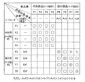
ここでは、具体例として図8に示されるように、4種類の中形部品の部品種P1〜P4および4種類の極小部品の部品種P5〜P8を装着する場合を考える。中形部品を収納したキャリアテープ5のテープ幅寸法W1は、極小部品を収納したキャリアテープ5のテープ幅寸法W2よりも大きい。このため、テープ幅寸法W1に対応する中形用テープフィーダF1〜F4、およびテープ幅寸法W2に対応する極小用テープフィーダF5〜F8が4台ずつ必要になる。なお、部品種に付した符号P1〜P8は部品種特定コードに相当し、テープフィーダに付した符号F1〜F8はフィーダ特定コードに相当している。
Here, as a specific example, as shown in FIG. 8, a case is considered in which four types of medium-sized component types P1 to P4 and four types of minimal component types P5 to P8 are mounted. The tape width dimension W1 of the
中形部品の部品種P1〜P4は、テープフィーダ32の供給位置32Sにおける許容位置精度が比較的緩く、中形用テープフィーダF1〜F4のいずれと組み合わせても吸着ミスのおそれは生じない。したがって、中形用テープフィーダF1〜F4では、位置精度の測定を省略する。
The medium-type component types P1 to P4 have relatively low permissible positional accuracy at the
一方、極小部品の部品種P5〜P8は、許容位置精度が厳しいので、アットランダムに極小用テープフィーダF5〜F8と組み合わせると、吸着ミスが頻発するおそれが生じる。補足すると、部品の部品外形寸法が小さいほど許容位置精度が厳しくなるのが一般的である。したがって、位置精度測定ステップS2で、オペレータは、フィーダ検査治具91を用いて4台の極小用テープフィーダF5〜F8の位置精度をそれぞれ測定する。なお、バックヤードへの保管時に位置精度測定ステップS2に相当する測定を行い測定結果が残されている場合には、再度の測定は省略してもよい。測定結果の一例として、第5テープフィーダF5で位置精度が最も低く、換言すると誤差Er5が最も大きく、以下、第6〜第8テープフィーダF6〜F8の順番に位置精度が高くなっているものとする。つまり、誤差Er5>誤差Er6>誤差Er7>誤差Er8の関係が成り立っているものとする。
On the other hand, the component types P5 to P8 of the extremely small parts have strict allowable position accuracy. Therefore, if they are combined at random with the tape feeders F5 to F8 for the minimum, there is a possibility that suction mistakes frequently occur. Supplementally, generally, the allowable position accuracy becomes stricter as the component outer dimension of the component is smaller. Accordingly, in the position accuracy measurement step S2, the operator measures the position accuracy of the four minimum tape feeders F5 to F8 using the
次の位置精度記憶ステップS3で、ホストコンピュータ92は、測定を行った第5〜第8テープフィーダF5〜F8を特定するフィーダ特定コードと位置精度(誤差Er5〜Er8)とを対応付けした位置精度データを記憶する。
In the next position accuracy storing step S3, the
次の部品種データ記憶ステップS4で、ジョブ管理コンピュータ93は、次に生産するプリント基板Kに装着する部品の部品種P1〜P8に関する部品種データを記憶する。部品種データは、部品種P1〜P8を特定する部品種特定コードと、当該部品種の部品外形寸法および許容位置精度の少なくとも一方とを対応付けしたデータである。ジョブ管理コンピュータ93は、部品種データを他装置から通信を介して取得してもよいし、持ち運びできるメモリ媒体から取得してもよいし、オペレータの入力操作から取得してもよい。具体例では、極小部品の部品種P5〜P8の各許容位置精度に相当する各許容位置誤差Av5〜Av8を考える。さらに、一例として、許容位置誤差Av5>許容位置誤差Av6>許容位置誤差Av7>許容位置誤差Av8の関係が成り立っているものとする。
In the next component type data storage step S4, the
次の部品種決定ステップS5で、ジョブ管理コンピュータ93は、まず、ホストコンピュータ92から第5〜第8テープフィーダF5〜F8の位置精度データを受け取る。ジョブ管理コンピュータ93は、次に、第5〜第8テープフィーダF5〜F8の位置精度(誤差Er5〜Er8)と、部品の部品種によって定まる部品外形寸法および当該部品がテープフィーダによって供給位置に供給されたときの許容位置精度の少なくとも一方とに基づいて、テープフィーダとキャリアテープに収納された部品の部品種との組合せを決定する。具体例で、ジョブ管理コンピュータ93は、第5〜第8テープフィーダF5〜F8の誤差Er5〜誤差Er8と、部品種P5〜P8によって定まる許容位置誤差Av5〜Av8とに基づいて、第5〜第8テープフィーダF5〜F8と部品種P5〜P8との組合せを決定する。
In the next component type determination step S <b> 5, the
図8において、各テープフィーダF1〜F8と部品種P1〜P8とが交差する合計64個の欄は、それぞれ組合せの可否を示している。すなわち、○印及び◎印は組合せ可を示し、×印は組合せ否を示し、空欄はテープ幅寸法W1、W2の不整合により物理的に組合せ否を示している。ここで、第5テープフィーダF5の誤差Er5が許容位置誤差Av6よりも小さくかつ許容位置誤差Av7よりも大きく、第6テープフィーダF6の誤差Er6が許容位置誤差Av8よりも小さいものとする。 In FIG. 8, a total of 64 columns where the tape feeders F1 to F8 and the component types P1 to P8 intersect indicate whether or not combinations are possible. In other words, ◯ and 印 indicate that combination is possible, x indicates that the combination is not possible, and a blank indicates physically that the combination is not possible due to mismatch of the tape width dimensions W1 and W2. Here, it is assumed that the error Er5 of the fifth tape feeder F5 is smaller than the allowable position error Av6 and larger than the allowable position error Av7, and the error Er6 of the sixth tape feeder F6 is smaller than the allowable position error Av8.
このとき、ジョブ管理コンピュータ93は、第5テープフィーダF5と部品種P7、P8との組合せを回避する(図8の×印)。つまり、第5テープフィーダF5の位置精度よりも部品種P7、P8の許容位置精度が厳しい場合に、ジョブ管理コンピュータ93は、当該テープフィーダF5と当該部品種P7、P8との組合せを回避する。これにより、位置精度の不良で吸着ミスが頻発することを防止できる。したがって、部品種決定ステップS5は、本発明の精度不良回避ステップを包含している。
At this time, the
さらに、ジョブ管理コンピュータ93は、第5〜第8テープフィーダF5〜F8の位置精度が高いほど許容位置精度が厳しい部品種と組み合わせ、第5〜第8テープフィーダF5〜F8の位置精度が低いほど許容位置精度が緩い部品種と組み合わせる。これにより、図8に◎印で示された組合せが採用される。つまり、誤差Er8が最も小さい第8テープフィーダF8と、許容位置誤差Av8の最も厳しい部品種P8とが組み合わせられる。以下、誤差Er7、Er6、Er5の小さい順に並べた第7、第6、および第5テープフィーダF7、F6、F5に対応して、許容位置誤差Av7、Av6、Av5の厳しい順に並べた部品種P7、P6、P5がそれぞれ組み合わせられる。
Further, the
なお、精度不良回避ステップは必須ではない。また、第5〜第8テープフィーダF5〜F8の位置精度の高さと部品種P5〜P8の許容位置精度の厳しさとを対応付けない方法を採用してもよい。つまり、図8において、第5〜第8テープフィーダF5〜F8と部品種P5〜P8との組合せを◎印だけに限定せず、◎印および○印を適宜組み合わせて採用してもよい。さらに、極小用テープフィーダの候補が5台以上あるときには、測定された位置精度に基づいて使用する4台を選択し、部品種P5〜P8との組合せを決定する。また、4台の中形用テープフィーダF1〜F4と中形部品の部品種P1〜P4の組み合わせは自由であり、○印のいずれの組合せを採用してもよい。 Note that the accuracy failure avoidance step is not essential. Further, a method in which the high positional accuracy of the fifth to eighth tape feeders F5 to F8 is not associated with the strictness of the allowable positional accuracy of the component types P5 to P8 may be employed. That is, in FIG. 8, the combination of the fifth to eighth tape feeders F5 to F8 and the component types P5 to P8 is not limited to ◎, but may be combined with ◎ and ○ as appropriate. Furthermore, when there are five or more candidates for the minimum tape feeder, four units to be used are selected based on the measured positional accuracy, and the combination with the component types P5 to P8 is determined. Further, the combination of the four medium-sized tape feeders F1 to F4 and the component types P1 to P4 of the medium-sized parts is free, and any combination indicated by ◯ may be adopted.
次のフィーダ割当てステップS6で、ジョブ管理コンピュータ93は、8台のテープフィーダF1〜F8の支持台31のスロットへの並び順を割り当てる。ここで、支持台31上の部品種P1〜P8の並び順に依存して、部品移載装置4の装着動作効率が変化する。このため、最適化された部品種P1〜P8の並び順が、ジョブ管理コンピュータ93または他装置のシミュレーションによって予め求められている場合が多い。したがって、ジョブ管理コンピュータ93は、最適化された部品種P1〜P8の並び順を実現するように、8台のテープフィーダF1〜F8の並び順を割り当てる。
In the next feeder assignment step S6, the
次に、ジョブ管理コンピュータ93は、割り当てた情報を部品実装機1に転送する。部品実装機1は、割り当てた情報を表示装置1Dに表示して、オペレータに案内する。案内表示として、例えば、図8に示された組合せ表をそのまま表示してもよく、これに限定されない。オペレータは、ステップS7で段取り方法を決め、機内段取りステップS8または機外段取りステップS9に進む。
Next, the
機内段取りステップS8で、オペレータは、部品供給装置3に装備された複数のテープフィーダF1〜F8の位置に応じた部品種P1〜P8の部品を収納したキャリアテープ5を各テープフィーダ32に装填して、各テープフィーダ32が各部品種P1〜P8の部品をそれぞれの供給位置32Sに供給できる状態に段取りする。つまり、オペレータは、まず、表示装置1Dの案内表示にしたがい、機台8に装備された支持台31の各テープフィーダF1〜F8のリール保持部39に適正な部品種P1〜P8のキャリアテープ5を保持させる。オペレータは、次に、支持台31上のテープフィーダ32の並び順を入れ替えて正しく整列させる。
In the in-machine setup step S8, the operator loads each
オペレータの機内段取り作業の各時点で、部品実装機1の制御コンピュータと、各テープフィーダF1〜F8の制御部37とは通信接続されている。したがって、制御コンピュータまたはジョブ管理コンピュータ93は、各テープフィーダF1〜F8と部品種P1〜P8との組合せが表示装置1Dの案内表示と一致した適正なものであるか否かを判定できる。さらに、制御コンピュータまたはジョブ管理コンピュータ93は、支持台31上のテープフィーダF1〜F8の並び順、すなわち部品種P1〜P8の並び順が表示装置1Dの案内表示と一致した適正なものであるか否かを判定できる。制御コンピュータまたはジョブ管理コンピュータ93は、判定結果を表示装置1Dに逐次案内表示して、機内段取り作業を支援する。
The control computer of the component mounting machine 1 and the
機外段取りステップS9で、オペレータは、部品実装機1から離れた場所で複数のテープフィーダF1〜F8にキャリアテープ5を装填して、各テープフィーダ32が部品をそれぞれの供給位置32Sに供給できる状態とし、各テープフィーダ32の並び順を整列させて段取りする。つまり、オペレータは、まず、表示装置1Dの案内表示にしたがい、部品実装機1から離れた場所で各テープフィーダF1〜F8のリール保持部39に適正な部品種P1〜P8のキャリアテープ5を保持させる。オペレータは、次に、部品実装機1の機台8から取り外された支持台31または予備の支持台31に各テープフィーダ32を正しく整列させる。オペレータは、最後に、各テープフィーダF1〜F8を支持台31とともに一括して機台8に装備する。
In the external setup step S9, the operator can load the
この時点で、部品実装機1の制御コンピュータと、各テープフィーダF1〜F8の制御部37とが通信接続される。したがって、制御コンピュータまたはジョブ管理コンピュータ93は、各テープフィーダF1〜F8と部品種P1〜P8との組合せが表示装置1Dの案内表示と一致した適正なものであるか否かを判定できる。さらに、制御コンピュータまたはジョブ管理コンピュータ93は、支持台31上のテープフィーダF1〜F8の並び順、すなわち部品種P1〜P8の並び順が表示装置1Dの案内表示と一致した適正なものであるか否かを判定できる。仮に、各テープフィーダF1〜F8と部品種P1〜P8との組合せやテープフィーダF1〜F8の並び順が適正でない場合、制御コンピュータまたはジョブ管理コンピュータ93は、表示装置1Dの案内表示を用いて、オペレータに訂正作業を指示する。
At this time, the control computer of the component mounting machine 1 and the
機内段取りステップS8または機外段取りステップS9が終了すると、ステップS10で、部品実装機1は、部品装着によるプリント基板Kの生産を開始する。生産を開始した以降、部品実装機1の制御コンピュータは、ステップS11でプリント基板Kの生産枚数が生産予定枚数に到達したか否かを判定し、ステップS12でいずれかのテープフィーダ32に部品補給が必要か否かを判定する。
When the in-machine setup step S8 or the out-of-machine setup step S9 is completed, in step S10, the component mounting machine 1 starts production of the printed circuit board K by component mounting. After starting the production, the control computer of the component mounting machine 1 determines whether or not the production number of the printed circuit boards K has reached the planned production number in step S11, and supplies a component to any
ステップS12で部品補給が必要な場合、部品補給時判定ステップS13に進む。この場合にオペレータは、部品切れとなるキャリアテープ5が装填されたテープフィーダ32に同じ部品種の部品を収納した次使用キャリアテープ5を装填する。制御コンピュータまたはジョブ管理コンピュータ93は、当該テープフィーダ32の位置精度と、次使用キャリアテープ5に収納された部品の部品種によって定まる部品外形寸法および許容位置精度の少なくとも一方との組合せの可否を判定する。
If part replenishment is necessary in step S12, the process proceeds to part supply determination step S13. In this case, the operator loads the next-
部品補給時に同一部品種の次使用キャリアテープ5を装填するとき、通常であれば許容位置精度は同等であり問題は生じない。しかしながら、部品メーカが異なっていたり、部品がマイナーチェンジされていたりすると、同一部品種であっても許容位置精度が異なる場合が有り得る。これを考慮して、部品補給時判定ステップS13を実施する。次使用キャリアテープ5に収納された部品の部品種データは、例えば、別途バーコードリーダで次使用キャリアテープ5を巻回したリールの部品種特定コードを読み取ることにより取得できる。したがって、制御コンピュータまたはジョブ管理コンピュータ93は、第5〜第8テープフィーダF5〜F8の位置精度データと、次使用キャリアテープ5に収容された部品の部品種データとから、組合せの可否を判定できる。
When the next-
ステップS11でプリント基板Kの生産枚数が生産予定枚数に到達すると、実施形態のフィーダ部品種決定方法の全ステップを終了する。次いで、プリント基板Kの別の種類を設定して、実施形態のフィーダ部品種決定方法を繰り返すことになる。 When the production number of printed circuit boards K reaches the production scheduled number in step S11, all steps of the feeder component type determination method of the embodiment are finished. Next, another type of the printed circuit board K is set, and the feeder component type determination method of the embodiment is repeated.
次に、機内段取りステップS8の応用形態について説明する。応用形態では、オペレータがテープフィーダ32にキャリアテープ5を装填する際の誤った装填作業を自動的に回避する。図9は、機内段取りステップS8の応用形態を説明するフロー図である。応用形態では、テープフィーダ32の挿入口32Eに挿入口規制機構(図略)を設ける。挿入口規制機構は、制御部37からの指令で動作して、挿入口32Eを完全に閉止したり、1つのキャリアテープ5だけを挿入できる半開にしたりできる。
Next, an application form of the in-machine setup step S8 will be described. In the application mode, an erroneous loading operation when the operator loads the
図9のコード識別ステップS31で、制御コンピュータまたはジョブ管理コンピュータ93は、これからキャリアテープ5を装填するテープフィーダF1〜F8のフィーダ特定コードおよび当該キャリアテープ5に収納された部品の部品種特定コードを識別する。このステップでは、例えば、オペレータがバーコードリーダを用いて、テープフィーダF1〜F8に付設されたフィーダ特定コードおよびキャリアテープ5を巻回したリールに付設された部品種特定コードを読み取る。これにより、制御コンピュータまたはジョブ管理コンピュータ93は、通信を介してフィーダ特定コードおよび部品種特定コードを識別することができる。
In the code identification step S31 of FIG. 9, the control computer or the
次の位置精度読取ステップS32で、制御コンピュータまたはジョブ管理コンピュータ93は、識別されたフィーダ特定コードにより特定されるテープフィーダF1〜F8の位置精度を位置精度データから読み取る。次の部品種読取ステップS33で、制御コンピュータまたはジョブ管理コンピュータ93は、識別された部品種特定コードにより特定される当該部品種の部品外形寸法および許容位置精度の少なくとも一方を部品種データから読み取る。
In the next position accuracy reading step S32, the control computer or
そして、次の組合せ判定ステップS34で、制御コンピュータまたはジョブ管理コンピュータ93は、読み取ったテープフィーダF1〜F8の位置精度と、読み取った当該部品種の部品外形寸法および許容位置精度の少なくとも一方とに基づいて、テープフィーダF1〜F8と当該キャリアテープ5に収納された部品の部品種との組合せの可否を判定する。つまり、制御コンピュータまたはジョブ管理コンピュータ93は、図8に示された空欄や×印の組合せのときに組合せ否と判定する。
Then, in the next combination determination step S34, the control computer or
組合せ否の判定時に、制御コンピュータまたはジョブ管理コンピュータ93は、当該のテープフィーダ32に挿入口32Eを閉止する指令を送る。これにより、テープフィーダ32の挿入口32Eが自動的に閉止されるので、オペレータは誤ったキャリアテープ5を装填できない。そこで、ステップS35でオペレータはリールを変更し、キャリアテープ5を変更してコード識別ステップS31に戻る。
At the time of determination of combination failure, the control computer or the
一方、組合せ可の判定時に、テープフィーダ32の挿入口32Eは閉止されないので、オペレータはキャリアテープ5の先端部をテープフィーダ32に装填できる。そして、ステップS36で、全てのテープフィーダ32へのキャリアテープ5の装填が終了したが否か判定する。未終了のときにはステップS37に進み、オペレータは、次のテープフィーダに移りコード識別ステップS31に戻る。ステップS36で終了のときには、図7のステップS10に戻って、プリント基板Kの生産を開始する。
On the other hand, since the
さらに、挿入口規制機構は、部品補給時判定ステップS13に応用することも可能である。すなわち、部品補給時判定ステップS13で、制御コンピュータまたはジョブ管理コンピュータ93は、テープフィーダF1〜F8と、次使用キャリアテープ5に収容された部品の部品種P1〜P8との組合せを否と判定したときに、当該のテープフィーダ32に挿入口32Eを半開とする指令を送る。これにより、テープフィーダ32の挿入口32Eが半開となり、オペレータは組合せ否と判定された次使用キャリアテープ5を誤って装填することがなくなる。
Furthermore, the insertion port restricting mechanism can be applied to the determination step S13 for parts supply. That is, in the part supply determination step S13, the control computer or the
なお、挿入口規制機構に代えて、テープフィーダ32のテープ送給機構35の停止制御を採用することもできる。つまり、テープフィーダ32の制御部37は、挿入口規制機構を制御して挿入口32Eを閉止したり半開したりする代わりに、テープ送給機構35のモータ351を停止制御する。これにより、第2スプロケット356は、組合せ否と判定された次使用キャリアテープ5を誤って引き込まず、オペレータは、次使用キャリアテープ5を装填し直すことができる。
Instead of the insertion port regulating mechanism, stop control of the
本実施形態のフィーダ部品種決定方法は、複数の部品Pを等ピッチLpで収納したキャリアテープ5をそれぞれ保持して部品Pをそれぞれの供給位置32Sに順次供給する複数のテープフィーダ32を着脱可能に装備する部品供給装置3と、供給位置32Sに供給された部品Pを吸着して装着実施位置に位置決めされたプリント基板Kに装着する部品移載装置4とを備えた部品実装機1で、複数のテープフィーダF1〜F8とキャリアテープ5に収納された部品Pの部品種P1〜P8との組合せを決定するフィーダ部品種決定方法であって、テープフィーダF1〜F8の少なくとも一部について、供給した部品Pの供給位置32Sでの位置精度を測定する位置精度測定ステップS2と、テープフィーダF5〜F8の位置精度と、部品Pの部品種P5〜P8によって定まる部品外形寸法および当該部品がテープフィーダ32によって供給位置32Sに供給されたときの許容位置精度の少なくとも一方とに基づいて、複数のテープフィーダF5〜F8とキャリアテープ5に収納された部品Pの部品種P5〜P8との組合せを決定する部品種決定ステップS5と、を有する。
In the feeder component type determination method of the present embodiment, a plurality of
これによれば、位置精度測定ステップS2で、テープフィーダF1〜F8の少なくとも一部について、供給した部品Pの供給位置32Sでの位置精度を測定するので、テープフィーダF5〜F8の供給位置32Sの位置精度の個体差や経年低下を個別にかつ正確に把握できる。そして、部品種決定ステップS5で、テープフィーダF5〜F8の位置精度(誤差Er5〜Er8)と、部品Pの部品種P5〜P8によって定まる部品外形寸法および許容位置精度(許容位置誤差Av5〜Av8)の少なくとも一方とに基づいて、テープフィーダF5〜F8とキャリアテープ5に収納された部品Pの部品種P5〜P8との組合せを決定する。つまり、各テープフィーダF5〜F8の位置精度に適合する適正な部品外形寸法や許容位置精度の部品種P5〜P8を選択し、組み合わせて使用することができる。これにより、テープフィーダF5〜F8の位置精度とキャリアテープ5に収納された部品Pの部品種P5〜P8との不適正な組合せが抑制されて、吸着ノズルによる部品の吸着動作が安定する。したがって、許容位置精度の厳しい極小部品に対しても吸着ミスを抑制でき、プリント基板Kの生産効率を高められる。
According to this, since the position accuracy at the
なお、部品実装機1、フィーダ検査治具91、ホストコンピュータ92、およびジョブ管理コンピュータ93の協業は、上述した実施形態での機能分担以外にも様々な形態での実施が可能である、例えば、ホストコンピュータ92を省略して、ホストコンピュータ92の役割をフィーダ検査治具91またはジョブ管理コンピュータ93で兼ねるようにできる。また例えば、部品種決定ステップS5はジョブ管理コンピュータ93で行う必要はなく、位置精度データおよび部品種データを共有する他装置で行ってもよい。さらに、テープフィーダ32の制御部37が自身の位置精度データを記憶保持し、部品実装機1に装備されたときに通信を介して位置精度データ転送するようにしてもよい。
The cooperation of the component mounter 1, the
また、図7の具体例で省略した中形用テープフィーダF1〜F4の位置精度の測定を行い、4種類の中形部品の部品種P1〜P4との組合せを最適化することもできる。また、5台以上の極小用テープフィーダの位置精度を測定した結果に基づいて、4台を選択使用するようにしてもよい。本発明は、その他にも様々な応用や変形が可能である。 Further, the position accuracy of the medium-sized tape feeders F1 to F4 omitted in the specific example of FIG. 7 can be measured, and the combination of the four types of medium-sized parts with the component types P1 to P4 can be optimized. Further, four units may be selectively used based on the result of measuring the positional accuracy of five or more minimum tape feeders. Various other applications and modifications are possible for the present invention.
さらに、本実施形態として、部品種決定ステップS2で、テープフィーダの位置精度が高いほど部品外形寸法が小さい部品種と組み合わせ、テープフィーダの位置精度が低いほど前記部品外形寸法が大きい部品種と組み合わせ、あるいは、テープフィーダF5〜F8の位置精度が高いほど(誤差Er5〜Er8が小さいほど)許容位置精度が厳しい(許容位置誤差Av5〜Av8が小さい)部品種P5〜P8と組み合わせ、テープフィーダF5〜F8の位置精度が低いほど許容位置精度が緩い部品種P5〜P8と組み合わせるフィーダ部品種決定方法を提示できる。 Further, in this embodiment, in the component type determination step S2, the higher the position accuracy of the tape feeder, the smaller the component outer dimension is combined, and the lower the tape feeder position accuracy, the larger the component outer dimension is combined. Alternatively, the higher the positional accuracy of the tape feeders F5 to F8 (the smaller the errors Er5 to Er8), the more severe the allowable positional accuracy (the smaller the allowable positional errors Av5 to Av8), in combination with the component types P5 to P8, and the tape feeder F5 It is possible to present a feeder component type determination method that is combined with component types P5 to P8 having a lower allowable positional accuracy as the positional accuracy of F8 is lower.
ここで、部品の部品外形寸法が小さいほど許容位置精度が厳しくなるのが一般的である。そして、本態様では、部品外形寸法が小さく許容位置精度が最も厳しい部品種P8に対して、位置精度が最も高い第8テープフィーダF8を優先的に組み合わせることができる。さらに以下同様に、許容位置精度の厳しさに対応して、位置精度が高いテープフィーダを組み合わせることができる。したがって、それぞれのテープフィーダF5〜F8と部品種P5〜P8との組合せにおける位置精度のマージンが比較的平均化され、マージンが極端に小さくなる組合せが生じない。これにより、テープフィーダF5〜F8の位置精度とキャリアテープ5に収納された部品Pの部品種P5〜P8との不適正な組合せが生じなくなり、吸着ノズルによる部品の吸着動作が確実に安定する。
Here, it is general that the allowable position accuracy becomes stricter as the component outer dimension of the component is smaller. In this aspect, the eighth tape feeder F8 having the highest positional accuracy can be preferentially combined with the component type P8 having the smallest component external dimension and the strictest allowable positional accuracy. Further, similarly, a tape feeder with high positional accuracy can be combined in accordance with the severity of allowable positional accuracy. Therefore, the margins of the positional accuracy in the combination of the tape feeders F5 to F8 and the component types P5 to P8 are relatively averaged, and there is no combination in which the margin becomes extremely small. Accordingly, an inappropriate combination of the positional accuracy of the tape feeders F5 to F8 and the component types P5 to P8 of the components P stored in the
さらに、本実施形態として、部品種決定ステップS5は、テープフィーダF5の位置精度(誤差Er5)よりも部品Pの部品種P7、P8によって定まる許容位置精度(許容位置誤差av7、Av8)が厳しい場合に、当該テープフィーダF5と当該部品種P7、P8との組合せを回避する精度不良回避ステップを包含するフィーダ部品種決定方法を提示できる。 Furthermore, in the present embodiment, in the component type determination step S5, the allowable position accuracy (allowable position errors av7, Av8) determined by the component types P7, P8 of the component P is more severe than the position accuracy (error Er5) of the tape feeder F5. In addition, it is possible to present a feeder component type determination method including a precision failure avoidance step for avoiding the combination of the tape feeder F5 and the component types P7 and P8.
これによれば、テープフィーダF5の位置精度が部品種P7、P8の許容位置精度よりも低くなる精度不適合を確実に回避でき、吸着ノズルによる部品の吸着動作が確実に安定する。 According to this, it is possible to reliably avoid the non-conformity that the positional accuracy of the tape feeder F5 is lower than the allowable positional accuracy of the component types P7 and P8, and the suction operation of the component by the suction nozzle is reliably stabilized.
さらに、本実施形態として、位置精度測定ステップS2に続いて、測定を行ったテープフィーダ32を特定するフィーダ特定コードと位置精度とを対応付けした位置精度データを記憶する位置精度記憶ステップS3と、部品の部品種を特定する部品種特定コードと、当該部品種の部品外形寸法および許容位置精度の少なくとも一方とを対応付けした部品種データを記憶する部品種データ記憶ステップS4と、を有し、部品種決定ステップS5で、位置精度データおよび部品種データに基づいて、複数のテープフィーダF5〜F8とキャリアテープ5に収納された部品Pの部品種P5〜P8との組合せを決定するフィーダ部品種決定方法を提示できる。
Furthermore, as this embodiment, following the position accuracy measurement step S2, a position accuracy storage step S3 for storing position accuracy data in which the feeder specifying code for specifying the
これによれば、部品種決定ステップS5は、ジョブ管理コンピュータ93で自動的に行うことができる。したがって、オペレータの手間が大いに省力化されて、プリント基板Kの生産効率を高められる。
According to this, the component type determination step S5 can be automatically performed by the
さらに、本実施形態として、部品種決定ステップS5に続いて、テープフィーダ32にキャリアテープ5を装填する際に、当該テープフィーダ32のフィーダ特定コードおよび当該キャリアテープ5に収納された部品Pの部品種特定コードを識別するコード識別ステップS31と、識別されたフィーダ特定コードにより特定されるテープフィーダ32の位置精度を位置精度データから読み取る位置精度読取ステップS32と、識別された部品種特定コードにより特定される当該部品種の部品外形寸法および許容位置精度の少なくとも一方を部品種データから読み取る部品種読取ステップS33と、読み取ったテープフィーダ32の位置精度と、読み取った当該部品種の部品外形寸法および許容位置精度の少なくとも一方とに基づいて、当該テープフィーダ32と当該キャリアテープ5に収納された部品Pの部品種との組合せの可否を判定する組合せ判定ステップS34と、を有するフィーダ部品種決定方法を提示できる。
Further, as the present embodiment, when the
これによれば、テープフィーダ32とキャリアテープ5に収納された部品Pの部品種との組合せの可否をジョブ管理コンピュータ93で自動的に行うことができる。したがって、オペレータがテープフィーダ32に適正でないキャリアテープ5を装填するおそれが抑制されて、プリント基板Kの生産効率を高められる。
According to this, the
さらに、本実施形態として、使用中のキャリアテープ5に収納された部品Pを供給位置32Sに順次供給可能であるとともに、次使用のキャリアテープ5の先端部5Tを準備位置(第1押圧部材362の底面の切欠き保持部362K)まで装填可能な次テープ装填形テープフィーダ32を用い、次テープ装填形テープフィーダ32の位置精度よりも次使用のキャリアテープ5に収納された部品の部品種によって定まる許容位置精度が厳しい場合に、精度不良回避ステップで、次使用のキャリアテープ5の先端部を次テープ装填形テープフィーダの準備位置まで装填することを回避するフィーダ部品種決定方法を提示できる。
Furthermore, as the present embodiment, the parts P housed in the
これによれば、次テープ装填形テープフィーダ32を用いた構成で、次使用のキャリアテープ5が精度不適合である場合に挿入口32Eが半開とされるので、オペレータが次使用キャリアテープ5を誤って装填することがなくなる。したがって、プリント基板Kの生産効率を高められる。
According to this, in the configuration using the next tape loading
さらに、本実施形態として、部品供給装置3に装備された複数のテープフィーダ32の位置に応じた部品種の部品Pを収納したキャリアテープ5を各テープフィーダ32に装填して、各テープフィーダ32が各部品種の部品Pをそれぞれの供給位置32Sに供給できる状態に段取りする場合に実施するフィーダ部品種決定方法を提示できる。
Further, as the present embodiment, the
これによれば、機内段取りステップS8を行う場合に本発明を実施して、プリント基板Kの生産効率を高められる。 According to this, the present invention is implemented when the in-machine setup step S8 is performed, and the production efficiency of the printed circuit board K can be improved.
さらに、本実施形態として、部品実装機1から離れた場所で複数のテープフィーダ32にキャリアテープ5を装填して、各テープフィーダ32が部品をそれぞれの供給位置32Sに供給できる状態とし、各テープフィーダ32の並び順を支持台31上に整列させて段取りする場合に実施するフィーダ部品種決定方法を提示できる。
Further, as the present embodiment, the
これによれば、機外段取りステップS9を行う場合に本発明を実施して、プリント基板Kの生産効率を高められる。 According to this, when the out-of-machine setup step S9 is performed, the present invention is implemented, and the production efficiency of the printed circuit board K can be improved.
さらに、本実施形態として、部品実装機1がプリント基板Kを生産している途中で、部品切れとなるキャリアテープ5が装填されたテープフィーダ32に同じ部品種の部品を収納した次使用キャリアテープ5を装填するときに、当該テープフィーダの位置精度と、次使用キャリアテープ5に収納された部品Pの部品種によって定まる部品外形寸法および許容位置精度の少なくとも一方との組合せの可否を判定する部品補給時判定ステップS13をさらに有するフィーダ部品種決定方法を提示できる。
Furthermore, as the present embodiment, the next-use carrier tape in which components of the same component type are housed in the
これによれば、プリント基板Kを生産している途中で部品を補給するときに、テープフィーダ32と次使用のキャリアテープ5の部品種との組合せが否である場合に、次使用のキャリアテープ5を誤って装填することがなくなる。したがって、プリント基板Kの生産効率を高められる。
According to this, when the parts are replenished during the production of the printed circuit board K, if the combination of the
さらに、本実施形態として、複数の部品Pを等ピッチLpで収納したキャリアテープ5をそれぞれ保持して部品Pをそれぞれの供給位置32Sに順次供給する複数のテープフィーダ32を着脱可能に装備する部品供給装置3と、供給位置32Sに供給された部品Pを吸着して装着実施位置に位置決めされたプリント基板Kに装着する部品移載装置4とを備えた部品実装機1で、複数のテープフィーダ32とキャリアテープ5に収納された部品Pの複数の部品種との組合せを決定するフィーダ部品種決定装置であって、テープフィーダF1〜F8の少なくとも一部について、供給した部品Pの供給位置32Sでの位置精度を測定するフィーダ検査治具91と、テープフィーダF5〜F8の位置精度(誤差Er5〜Er8)と、部品Pの部品種P5〜P8によって定まる部品外形寸法および当該部品がテープフィーダ32によって供給位置32Sに供給されたときの許容位置精度(許容位置誤差Av5〜Av8)の少なくとも一方とに基づいて、テープフィーダF5〜F8とキャリアテープ5に収納された部品Pの部品種P5〜P8との組合せを決定するジョブ管理コンピュータ93と、を有するフィーダ部品種決定装置を提示できる。
Further, as the present embodiment, a component that is detachably equipped with a plurality of
これによれば、本実施形態は装置として実施することもでき、前に提示したフィーダ部品種決定方法の各効果が発生する。 According to this, this embodiment can also be implemented as an apparatus, and each effect of the feeder component type determination method presented previously occurs.
1:部品実装機 2:基板搬送装置 3:部品供給装置
31:支持台 32:テープフィーダ 32E:挿入口
32S:供給位置 33:フィーダ筺体 34:レール
35:テープ送給機構 36:次使用テープ制御機構
37:制御部 39:リール保持部
4:部品移載装置
5:キャリアテープ 5T:先端部 51:ベーステープ
511:収納凹部 52:カバーテープ 53:ボトムテープ
6:測定用テープ 61:測定用マーカ
8:機台
91フィーダ検査治具 911:支持台
912:通信用ソケット 913:撮像カメラ
914:治具制御部
92:ホストコンピュータ 93:ジョブ管理コンピュータ
K:プリント基板 P:部品 Lp:ピッチ1: Component mounter 2: Board transfer device 3: Component supply device 31: Support base 32:
Claims (9)
前記テープフィーダの少なくとも一部である複数の前記テープフィーダの各々について、前記供給位置での位置精度を測定する位置精度測定ステップと、
前記位置精度を測定された前記テープフィーダの各々の前記位置精度と、前記部品の前記部品種によって定まる部品外形寸法および当該の前記部品が前記テープフィーダによって前記供給位置に供給されたときの許容位置精度の少なくとも一方とに基づいて、前記位置精度を測定され、かつ前記プリント基板に装着する前記部品を供給するために使用される前記テープフィーダの各々と前記キャリアテープに収納された前記部品の前記部品種との組合せを決定する部品種決定ステップと、を有し、
前記部品種決定ステップで、
前記テープフィーダの前記位置精度が高いほど前記部品外形寸法が小さい前記部品種と組み合わせ、前記テープフィーダの前記位置精度が低いほど前記部品外形寸法が大きい前記部品種と組み合わせるフィーダ部品種決定方法。 A component supply device detachably equipped with a plurality of tape feeders that respectively hold carrier tapes that store a plurality of components at an equal pitch and sequentially supply the components to respective supply positions, and the component supply device supplied to the supply positions A component mounting machine comprising a component transfer device for adsorbing a component and mounting the component on a printed circuit board positioned at a mounting position, and a plurality of component types of the component stored in the plurality of tape feeders and the carrier tape A feeder part type determination method for determining a combination with
A position accuracy measurement step for measuring the position accuracy at the supply position for each of the plurality of tape feeders that are at least part of the tape feeder;
The position accuracy of each of the tape feeders for which the position accuracy has been measured, the component outer dimensions determined by the component type of the component, and the permissible position when the component is supplied to the supply position by the tape feeder. Each of the tape feeders used to supply the component to be mounted on the printed circuit board and the component housed in the carrier tape, the positional accuracy of which is measured based on at least one of the accuracy It possesses a component type determining step of determining a combination of a component type, a,
In the part type determination step,
A feeder component type determination method that combines with the component type having a smaller component outer dimension as the positional accuracy of the tape feeder is higher, and combined with the component type with a larger component outer dimension as the positional accuracy of the tape feeder is lower .
前記測定を行った前記テープフィーダを特定するフィーダ特定コードと前記位置精度とを対応付けした位置精度データを記憶する位置精度記憶ステップと、
前記部品の前記部品種を特定する部品種特定コードと、当該の前記部品種の前記部品外形寸法および前記許容位置精度の少なくとも一方とを対応付けした部品種データを記憶する部品種データ記憶ステップと、をさらに有し、
前記部品種決定ステップで、前記位置精度データおよび前記部品種データに基づいて、前記位置精度を測定された前記テープフィーダの各々と前記キャリアテープに収納された前記部品の前記部品種との組合せを決定する請求項1または2に記載のフィーダ部品種決定方法。 Following the position accuracy measurement step,
A position accuracy storage step for storing position accuracy data in which the position accuracy is associated with a feeder specifying code for specifying the tape feeder that has performed the measurement;
A component type data storage step for storing component type data in which the component type specifying code for specifying the component type of the component is associated with at least one of the component external dimensions and the allowable position accuracy of the component type; Further comprising
Based on the position accuracy data and the component type data in the component type determination step, a combination of each of the tape feeders for which the position accuracy is measured and the component types of the components stored in the carrier tape The feeder part kind determination method according to claim 1 or 2 , wherein the feeder part type is determined.
前記テープフィーダに前記キャリアテープを装填する際に、当該の前記テープフィーダの前記フィーダ特定コードおよび当該の前記キャリアテープに収納された前記部品の前記部品種特定コードを識別するコード識別ステップと、
識別された前記フィーダ特定コードにより特定される前記テープフィーダの前記位置精度を前記位置精度データから読み取る位置精度読取ステップと、
識別された前記部品種特定コードにより特定される当該の前記部品種の前記部品外形寸法および前記許容位置精度の少なくとも一方を前記部品種データから読み取る部品種読取ステップと、
読み取った前記テープフィーダの前記位置精度と、読み取った当該の前記部品種の前記部品外形寸法および前記許容位置精度の少なくとも一方とに基づいて、当該の前記テープフィーダと当該の前記キャリアテープに収納された前記部品の前記部品種との組合せの可否を判定する組合せ判定ステップと、をさらに有する請求項3に記載のフィーダ部品種決定方法。 Following the part type determination step,
A code identification step for identifying the feeder identification code of the tape feeder and the component type identification code of the component housed in the carrier tape when the carrier tape is loaded into the tape feeder;
A position accuracy reading step of reading the position accuracy of the tape feeder specified by the identified feeder specifying code from the position accuracy data;
A component type reading step of reading at least one of the component external dimensions and the allowable position accuracy of the component type specified by the identified component type specifying code from the component type data;
Based on the read position accuracy of the tape feeder and at least one of the read component external dimensions and the allowable position accuracy of the component type, the tape feeder is stored in the tape feeder and the carrier tape. The feeder component type determination method according to claim 3 , further comprising a combination determination step of determining whether or not the component can be combined with the component type.
前記組合せ判定ステップは、前記次テープ装填形テープフィーダの前記位置精度よりも前記次使用の前記キャリアテープに収納された前記部品の前記部品種によって定まる前記許容位置精度が厳しい場合に、前記次使用の前記キャリアテープの先端部を前記次テープ装填形テープフィーダの前記準備位置まで装填することを回避する誤装填回避ステップを包含する請求項4に記載のフィーダ部品種決定方法。 Using the next tape loading type tape feeder that can sequentially supply the parts housed in the carrier tape in use to the supply position and can load the leading end of the carrier tape in the next use to the preparation position,
In the combination determination step, when the allowable position accuracy determined by the component type of the component stored in the carrier tape of the next use is stricter than the position accuracy of the next tape loading type tape feeder, the next use is performed. 5. The feeder component type determination method according to claim 4 , further comprising an erroneous loading avoidance step for avoiding loading the leading end portion of the carrier tape to the preparation position of the next tape loading type tape feeder.
前記テープフィーダの少なくとも一部である複数の前記テープフィーダの各々について、前記供給位置での位置精度を測定する位置精度測定手段と、
前記位置精度を測定された前記テープフィーダの各々の前記位置精度と、前記部品の前記部品種によって定まる部品外形寸法および当該の前記部品が前記テープフィーダによって前記供給位置に供給されたときの許容位置精度の少なくとも一方とに基づいて、前記位置精度を測定され、かつ前記プリント基板に装着する前記部品を供給するために使用される前記テープフィーダの各々と前記キャリアテープに収納された前記部品の前記部品種との組合せを決定する部品種決定手段と、を有し、
前記部品種決定手段は、
前記テープフィーダの前記位置精度が高いほど前記部品外形寸法が小さい前記部品種と組み合わせ、前記テープフィーダの前記位置精度が低いほど前記部品外形寸法が大きい前記部品種と組み合わせるフィーダ部品種決定装置。 A component supply device detachably equipped with a plurality of tape feeders that respectively hold carrier tapes that store a plurality of components at an equal pitch and sequentially supply the components to respective supply positions, and the component supply device supplied to the supply positions A component mounting machine comprising a component transfer device for adsorbing a component and mounting the component on a printed circuit board positioned at a mounting position, and a plurality of component types of the component stored in the plurality of tape feeders and the carrier tape A feeder part type determination device for determining a combination with
Position accuracy measuring means for measuring the position accuracy at the supply position for each of the plurality of tape feeders that are at least part of the tape feeder;
The position accuracy of each of the tape feeders for which the position accuracy has been measured, the component outer dimensions determined by the component type of the component, and the permissible position when the component is supplied to the supply position by the tape feeder. Each of the tape feeders used to supply the component to be mounted on the printed circuit board and the component housed in the carrier tape, the positional accuracy of which is measured based on at least one of the accuracy And a component type determining means for determining a combination with the component type,
The component type determining means includes
A feeder component type determining device that combines with the component type having a smaller component outer dimension as the positional accuracy of the tape feeder is higher, and combined with the component type with a larger component outer dimension as the positional accuracy of the tape feeder is lower .
Applications Claiming Priority (1)
| Application Number | Priority Date | Filing Date | Title |
|---|---|---|---|
| PCT/JP2013/072299 WO2015025383A1 (en) | 2013-08-21 | 2013-08-21 | Feeder component type determination method and feeder component type determination device |
Publications (2)
| Publication Number | Publication Date |
|---|---|
| JPWO2015025383A1 JPWO2015025383A1 (en) | 2017-03-02 |
| JP6334538B2 true JP6334538B2 (en) | 2018-05-30 |
Family
ID=52483193
Family Applications (1)
| Application Number | Title | Priority Date | Filing Date |
|---|---|---|---|
| JP2015532618A Active JP6334538B2 (en) | 2013-08-21 | 2013-08-21 | Feeder part type determination method and feeder part type determination apparatus |
Country Status (5)
| Country | Link |
|---|---|
| US (1) | US10130019B2 (en) |
| EP (1) | EP3038443B1 (en) |
| JP (1) | JP6334538B2 (en) |
| CN (1) | CN105474769B (en) |
| WO (1) | WO2015025383A1 (en) |
Cited By (1)
| Publication number | Priority date | Publication date | Assignee | Title |
|---|---|---|---|---|
| WO2024024016A1 (en) * | 2022-07-28 | 2024-02-01 | 株式会社Fuji | Reel sorting apparatus |
Families Citing this family (18)
| Publication number | Priority date | Publication date | Assignee | Title |
|---|---|---|---|---|
| JP6449431B2 (en) * | 2015-03-06 | 2019-01-09 | 株式会社Fuji | Optimization method for component type allocation and component type allocation optimization device |
| JP7349463B2 (en) * | 2015-08-25 | 2023-09-22 | 株式会社Fuji | Feeder maintenance system and feeder maintenance system control method |
| WO2017033283A1 (en) * | 2015-08-25 | 2017-03-02 | 富士機械製造株式会社 | Feeder maintenance device and method for controlling same |
| WO2017037879A1 (en) * | 2015-09-01 | 2017-03-09 | 富士機械製造株式会社 | Work allocation device |
| US10667447B2 (en) * | 2016-03-30 | 2020-05-26 | Yamaha Hatsudoki Kabushiki Kaisha | Components feeder |
| US11039557B2 (en) * | 2016-04-13 | 2021-06-15 | Fuji Corporation | Mounting apparatus and mounting method |
| US11019760B2 (en) * | 2016-06-13 | 2021-05-25 | Fuji Corporation | Feeder management method and feeder management device |
| EP3584651A4 (en) * | 2017-02-14 | 2020-03-25 | Fuji Corporation | Substrate manufacturing machine and substrate manufacturing line |
| JP6926277B2 (en) * | 2017-02-14 | 2021-08-25 | 株式会社Fuji | Board production machine, board production line, and line management equipment |
| US11612091B2 (en) | 2017-10-31 | 2023-03-21 | Yamaha Hatsudoki Kabushiki Kaisha | Feeder management device and component-mounting system provided with same |
| WO2019162984A1 (en) * | 2018-02-20 | 2019-08-29 | 株式会社Fuji | Tape feeder support plate type/component type combination verification system and support plate type/component type combination verification method |
| EP3829284B1 (en) * | 2018-07-24 | 2023-11-15 | Fuji Corporation | Information processing device, work system, and determination method |
| CN113170610B (en) * | 2018-12-03 | 2022-10-11 | 松下知识产权经营株式会社 | Component mounting system, tape feeder, and component mounting device |
| US20220132715A1 (en) * | 2018-12-10 | 2022-04-28 | Panasonic Intellectual Property Management Co., Ltd. | Component mounting device and component mounting method |
| EP3917302A4 (en) * | 2019-01-25 | 2022-01-26 | Fuji Corporation | Feeder determination method and feeder determination device |
| CN112055529B (en) * | 2019-06-06 | 2022-04-05 | 深圳市瑞微智能有限责任公司 | Feeding method and feeding assembly for SMT chip mounter |
| JPWO2021010033A1 (en) * | 2019-07-18 | 2021-01-21 | ||
| WO2023062680A1 (en) * | 2021-10-11 | 2023-04-20 | 株式会社Fuji | Management apparatus and management method |
Family Cites Families (25)
| Publication number | Priority date | Publication date | Assignee | Title |
|---|---|---|---|---|
| US4663615A (en) | 1984-12-26 | 1987-05-05 | International Business Machines Corporation | Document creation |
| JP2662948B2 (en) | 1986-10-30 | 1997-10-15 | ニツト− システム テクノロジ− インコ−ポレ−テツド | Chip tape top tape removal device |
| US5339939A (en) * | 1992-08-31 | 1994-08-23 | Cna Manufacturing Systems, Inc. | Pocket tape feeder system |
| JP3802955B2 (en) * | 1996-11-27 | 2006-08-02 | 富士機械製造株式会社 | Circuit component mounting system |
| JP4331301B2 (en) * | 1999-02-24 | 2009-09-16 | 富士機械製造株式会社 | Electrical component mounting machine and electrical component mounting method |
| US6739036B2 (en) * | 2000-09-13 | 2004-05-25 | Fuji Machine Mfg., Co., Ltd. | Electric-component mounting system |
| JP4616514B2 (en) * | 2001-06-07 | 2011-01-19 | 富士機械製造株式会社 | Electrical component mounting system and position error detection method therefor |
| JP3997101B2 (en) * | 2002-03-18 | 2007-10-24 | 富士機械製造株式会社 | Electronic circuit component mounting system |
| JP2004140162A (en) | 2002-10-17 | 2004-05-13 | Fuji Mach Mfg Co Ltd | Method for maintenance of electronic circuit component mounting device, method for monitoring operation state of electronic circuit component mounting device, and electronic circuit manufacturing support system |
| US7273166B2 (en) * | 2002-11-11 | 2007-09-25 | Fuji Machine Mfg. Co., Ltd. | Component information applying method and apparatus |
| JP4491418B2 (en) * | 2003-07-18 | 2010-06-30 | 富士機械製造株式会社 | Support work management apparatus for board work system and support work management program for board work system |
| US7073696B2 (en) * | 2003-11-24 | 2006-07-11 | Tyco Electronics Corporation | High repeatability tape feeder for electronic component carrier tapes |
| JP2005216946A (en) * | 2004-01-27 | 2005-08-11 | Yamaha Motor Co Ltd | Method and apparatus for managing remaining number of components in packaging machine |
| JP4715484B2 (en) * | 2005-12-06 | 2011-07-06 | パナソニック株式会社 | Tape feeder adjustment system |
| JP4882411B2 (en) * | 2006-02-22 | 2012-02-22 | パナソニック株式会社 | Feeder adjusting device, feeder adjusting method and tape feeder |
| WO2008152701A1 (en) * | 2007-06-13 | 2008-12-18 | Fujitsu Limited | Method for taking out electronic component from carrier tape |
| US8153201B2 (en) | 2007-10-23 | 2012-04-10 | Semiconductor Energy Laboratory Co., Ltd. | Method of manufacturing light-emitting device, and evaporation donor substrate |
| JP4932683B2 (en) * | 2007-11-14 | 2012-05-16 | ヤマハ発動機株式会社 | Component supply method, surface mounter and cart |
| JP2009140994A (en) | 2007-12-04 | 2009-06-25 | Fuji Mach Mfg Co Ltd | Method and device of peeling top tape in tape feeder |
| JP4952692B2 (en) * | 2008-09-19 | 2012-06-13 | パナソニック株式会社 | Electronic component mounting apparatus and electronic component mounting method |
| JP5434884B2 (en) * | 2010-10-27 | 2014-03-05 | パナソニック株式会社 | Electronic component mounting apparatus and electronic component mounting method |
| JP2013012572A (en) * | 2011-06-29 | 2013-01-17 | Panasonic Corp | Tape feeder |
| JP5846628B2 (en) * | 2011-09-15 | 2016-01-20 | 富士機械製造株式会社 | Feeder mounting structure |
| JP5807158B2 (en) * | 2011-11-01 | 2015-11-10 | パナソニックIpマネジメント株式会社 | Feeder ranking apparatus and feeder ranking method for electronic component mounting apparatus |
| CN104170540B (en) * | 2012-03-13 | 2016-12-21 | 富士机械制造株式会社 | The feeder management system of component mounter |
-
2013
- 2013-08-21 CN CN201380078990.4A patent/CN105474769B/en active Active
- 2013-08-21 US US14/913,139 patent/US10130019B2/en active Active
- 2013-08-21 EP EP13891775.2A patent/EP3038443B1/en active Active
- 2013-08-21 WO PCT/JP2013/072299 patent/WO2015025383A1/en active Application Filing
- 2013-08-21 JP JP2015532618A patent/JP6334538B2/en active Active
Cited By (1)
| Publication number | Priority date | Publication date | Assignee | Title |
|---|---|---|---|---|
| WO2024024016A1 (en) * | 2022-07-28 | 2024-02-01 | 株式会社Fuji | Reel sorting apparatus |
Also Published As
| Publication number | Publication date |
|---|---|
| US20160212897A1 (en) | 2016-07-21 |
| EP3038443A4 (en) | 2016-09-21 |
| WO2015025383A1 (en) | 2015-02-26 |
| CN105474769A (en) | 2016-04-06 |
| EP3038443A1 (en) | 2016-06-29 |
| EP3038443B1 (en) | 2020-10-21 |
| JPWO2015025383A1 (en) | 2017-03-02 |
| CN105474769B (en) | 2018-12-21 |
| US10130019B2 (en) | 2018-11-13 |
Similar Documents
| Publication | Publication Date | Title |
|---|---|---|
| JP6334538B2 (en) | Feeder part type determination method and feeder part type determination apparatus | |
| JP5675013B2 (en) | Electronic circuit assembly method and electronic circuit assembly system | |
| JP6681344B2 (en) | Feeder device | |
| US10869420B2 (en) | Method for optimizing component type allocation and apparatus for optimizing component type allocation | |
| US10902161B2 (en) | Method for optimizing component type arrangement and apparatus for optimizing component type arrangement | |
| US9310789B2 (en) | Component verification method and component verification system | |
| US10420262B2 (en) | Feeder management device | |
| WO2012063624A1 (en) | Component matching method, and component mounting system | |
| JP6612850B2 (en) | Feeder device and component mounting machine | |
| JP6431048B2 (en) | feeder | |
| US20080283191A1 (en) | Tape Feeder and Electronic-Circuit-Component Supplying Apparatus | |
| US11019760B2 (en) | Feeder management method and feeder management device | |
| JP6561045B2 (en) | Tape unauthorized insertion detection device | |
| JP6847214B2 (en) | Parts judgment system and parts judgment method | |
| US20220117126A1 (en) | Setup change task setting device | |
| WO2016203637A1 (en) | Component-mounting system | |
| CN107114007B (en) | Electronic component supply system | |
| JP6956431B2 (en) | Feeder device | |
| JP6905302B2 (en) | Control device, board production system and board production method | |
| JP2018010998A (en) | Feeder device | |
| JP6334686B2 (en) | Component mounter | |
| JP2021012919A (en) | Component mounting device and method for manufacturing component mounting device |
Legal Events
| Date | Code | Title | Description |
|---|---|---|---|
| A131 | Notification of reasons for refusal |
Free format text: JAPANESE INTERMEDIATE CODE: A131 Effective date: 20170606 |
|
| A521 | Request for written amendment filed |
Free format text: JAPANESE INTERMEDIATE CODE: A523 Effective date: 20170731 |
|
| A131 | Notification of reasons for refusal |
Free format text: JAPANESE INTERMEDIATE CODE: A131 Effective date: 20171121 |
|
| A521 | Request for written amendment filed |
Free format text: JAPANESE INTERMEDIATE CODE: A523 Effective date: 20180119 |
|
| TRDD | Decision of grant or rejection written | ||
| A01 | Written decision to grant a patent or to grant a registration (utility model) |
Free format text: JAPANESE INTERMEDIATE CODE: A01 Effective date: 20180403 |
|
| A61 | First payment of annual fees (during grant procedure) |
Free format text: JAPANESE INTERMEDIATE CODE: A61 Effective date: 20180426 |
|
| R150 | Certificate of patent or registration of utility model |
Ref document number: 6334538 Country of ref document: JP Free format text: JAPANESE INTERMEDIATE CODE: R150 |
|
| R250 | Receipt of annual fees |
Free format text: JAPANESE INTERMEDIATE CODE: R250 |
|
| R250 | Receipt of annual fees |
Free format text: JAPANESE INTERMEDIATE CODE: R250 |
|
| R250 | Receipt of annual fees |
Free format text: JAPANESE INTERMEDIATE CODE: R250 |