JP6325309B2 - Seat holder - Google Patents
Seat holder Download PDFInfo
- Publication number
- JP6325309B2 JP6325309B2 JP2014069589A JP2014069589A JP6325309B2 JP 6325309 B2 JP6325309 B2 JP 6325309B2 JP 2014069589 A JP2014069589 A JP 2014069589A JP 2014069589 A JP2014069589 A JP 2014069589A JP 6325309 B2 JP6325309 B2 JP 6325309B2
- Authority
- JP
- Japan
- Prior art keywords
- dot
- sheet
- adhesive
- dots
- row
- Prior art date
- Legal status (The legal status is an assumption and is not a legal conclusion. Google has not performed a legal analysis and makes no representation as to the accuracy of the status listed.)
- Active
Links
- 239000000853 adhesive Substances 0.000 claims description 137
- 230000001070 adhesive effect Effects 0.000 claims description 136
- 239000000463 material Substances 0.000 claims description 28
- 238000005520 cutting process Methods 0.000 claims description 16
- 239000000758 substrate Substances 0.000 claims description 13
- 230000015572 biosynthetic process Effects 0.000 claims description 11
- 238000003825 pressing Methods 0.000 claims description 8
- 239000000123 paper Substances 0.000 description 16
- 239000004820 Pressure-sensitive adhesive Substances 0.000 description 13
- 230000037303 wrinkles Effects 0.000 description 11
- 239000011087 paperboard Substances 0.000 description 4
- 230000014759 maintenance of location Effects 0.000 description 3
- 230000000694 effects Effects 0.000 description 2
- -1 polyethylene terephthalate Polymers 0.000 description 2
- 229920000139 polyethylene terephthalate Polymers 0.000 description 2
- 239000005020 polyethylene terephthalate Substances 0.000 description 2
- 238000003491 array Methods 0.000 description 1
- 239000004744 fabric Substances 0.000 description 1
- 238000000034 method Methods 0.000 description 1
- 230000002093 peripheral effect Effects 0.000 description 1
- 239000002985 plastic film Substances 0.000 description 1
- 229920006289 polycarbonate film Polymers 0.000 description 1
Images


Classifications
-
- B—PERFORMING OPERATIONS; TRANSPORTING
- B43—WRITING OR DRAWING IMPLEMENTS; BUREAU ACCESSORIES
- B43L—ARTICLES FOR WRITING OR DRAWING UPON; WRITING OR DRAWING AIDS; ACCESSORIES FOR WRITING OR DRAWING
- B43L3/00—Writing or drawing underlays, e.g. blotting pads
-
- B—PERFORMING OPERATIONS; TRANSPORTING
- B26—HAND CUTTING TOOLS; CUTTING; SEVERING
- B26D—CUTTING; DETAILS COMMON TO MACHINES FOR PERFORATING, PUNCHING, CUTTING-OUT, STAMPING-OUT OR SEVERING
- B26D7/00—Details of apparatus for cutting, cutting-out, stamping-out, punching, perforating, or severing by means other than cutting
- B26D7/01—Means for holding or positioning work
- B26D7/015—Means for holding or positioning work for sheet material or piles of sheets
-
- B—PERFORMING OPERATIONS; TRANSPORTING
- B41—PRINTING; LINING MACHINES; TYPEWRITERS; STAMPS
- B41J—TYPEWRITERS; SELECTIVE PRINTING MECHANISMS, i.e. MECHANISMS PRINTING OTHERWISE THAN FROM A FORME; CORRECTION OF TYPOGRAPHICAL ERRORS
- B41J11/00—Devices or arrangements of selective printing mechanisms, e.g. ink-jet printers or thermal printers, for supporting or handling copy material in sheet or web form
- B41J11/02—Platens
- B41J11/13—Backings or blankets
-
- B—PERFORMING OPERATIONS; TRANSPORTING
- B41—PRINTING; LINING MACHINES; TYPEWRITERS; STAMPS
- B41J—TYPEWRITERS; SELECTIVE PRINTING MECHANISMS, i.e. MECHANISMS PRINTING OTHERWISE THAN FROM A FORME; CORRECTION OF TYPOGRAPHICAL ERRORS
- B41J13/00—Devices or arrangements of selective printing mechanisms, e.g. ink-jet printers or thermal printers, specially adapted for supporting or handling copy material in short lengths, e.g. sheets
- B41J13/10—Sheet holders, retainers, movable guides, or stationary guides
- B41J13/14—Aprons or guides for the printing section
- B41J13/16—Aprons or guides for the printing section movable for insertion or release of sheets
-
- B—PERFORMING OPERATIONS; TRANSPORTING
- B43—WRITING OR DRAWING IMPLEMENTS; BUREAU ACCESSORIES
- B43L—ARTICLES FOR WRITING OR DRAWING UPON; WRITING OR DRAWING AIDS; ACCESSORIES FOR WRITING OR DRAWING
- B43L13/00—Drawing instruments, or writing or drawing appliances or accessories not otherwise provided for
-
- B—PERFORMING OPERATIONS; TRANSPORTING
- B43—WRITING OR DRAWING IMPLEMENTS; BUREAU ACCESSORIES
- B43L—ARTICLES FOR WRITING OR DRAWING UPON; WRITING OR DRAWING AIDS; ACCESSORIES FOR WRITING OR DRAWING
- B43L5/00—Drawing boards
Landscapes
- Life Sciences & Earth Sciences (AREA)
- Forests & Forestry (AREA)
- Engineering & Computer Science (AREA)
- Mechanical Engineering (AREA)
- Control Of Cutting Processes (AREA)
- Details Of Cutting Devices (AREA)
Description
本発明は、シートホルダーに係り、特に、プロッターがシートに加工処理を行っている間にシートを保持しておくためのシートホルダーに関する。 The present invention relates to a sheet holder, and more particularly to a sheet holder for holding a sheet while a plotter is processing the sheet.
従来、載置台に載置されたシートを駆動ローラと加圧ローラとで挟持し、駆動ローラの回転動作によってシートを搬送しながら、ペン又はカッターを保持したキャリッジを搬送方向と直交方向に動作させることで、シート上に所定画像又は所定の切断画像を形成するプロッターが知られている。
また、比較的厚みの薄いシートの場合には、プロッターの作画又は切断動作時にシートが撓むことのないように、予めシートの下敷きとなるシートホルダーをシートに剥離可能に貼り付けておく技術が知られている(例えば、特許文献1参照)。
Conventionally, a sheet placed on a placing table is sandwiched between a driving roller and a pressure roller, and a carriage holding a pen or a cutter is operated in a direction orthogonal to the conveying direction while the sheet is conveyed by a rotation operation of the driving roller. Thus, a plotter that forms a predetermined image or a predetermined cut image on a sheet is known.
In addition, in the case of a relatively thin sheet, there is a technique in which a sheet holder, which serves as an underlay for the sheet, is attached to the sheet in a peelable manner so that the sheet does not bend during plotting or cutting operation of the plotter. It is known (see, for example, Patent Document 1).
特許文献1に記載のペンプロッターでは、被作画媒体となる用紙の裏面に裏打ちシート材を貼り付けた上で、この用紙を搬送しながら同時に搬送方向と直交方向にペンを動作させる構成とすることで、この用紙上に高筆記圧で作画することできる。
このとき、裏打ちシート材は、シート基材上に不連続なスポット状の粘着剤が設けられた構成となっている。
The pen plotter described in
At this time, the backing sheet material has a configuration in which a discontinuous spot-like adhesive is provided on the sheet base material.
ところで、上記のようなシートホルダーは、プロッターの作画又は切断動作時には、シートを撓ませないように粘着する粘着強度が必要とされるが、一方で、所定の画像形成後には、利用者がシートを容易に剥がせるように粘着強度を調整する必要がある。
特に、薄葉紙からなるシートの場合には、例えばシートホルダー上面の略全体にわたって粘着剤が塗布されていると粘着強度が比較的強くなるため、所定の画像形成後にシートホルダーからシートを剥がそうとするときに、強い引っ張り力が加わってシートが塑性変形してしまい、皺やカールが発生してしまう恐れがある。
なお、粘着剤の粘着濃度を調整することで、粘着強度を弱めることができるが、粘着強度は、温度や湿度などによっても変化するため、粘着濃度を管理することは困難である。
By the way, the sheet holder as described above needs an adhesive strength to adhere the sheet so as not to bend during the plotting or cutting operation of the plotter. It is necessary to adjust the adhesive strength so that can be easily peeled off.
In particular, in the case of a sheet made of thin paper, for example, if the adhesive is applied over substantially the entire upper surface of the sheet holder, the adhesive strength becomes relatively strong, so it is attempted to peel off the sheet from the sheet holder after predetermined image formation. Sometimes, a strong tensile force is applied and the sheet is plastically deformed, which may cause wrinkles and curls.
It should be noted that the adhesive strength can be weakened by adjusting the adhesive concentration of the adhesive, but it is difficult to manage the adhesive concentration because the adhesive strength changes depending on temperature, humidity, and the like.
特許文献1のようなシートホルダーでは、シート基材上に不連続なスポット状の粘着剤が設けられているため、シート基材上の全面にわたって粘着剤が設けられている場合と比較して、シートを剥がし易くする工夫が一応なされているものの、プロッターの画像形成時にシートを確実に保持するためには、粘着強度が比較的劣る傾向にあった。
特に、薄葉紙からなるシートの場合に加えて、プロッターが切断画像の形成を主目的としたカッティングプロッターの場合には、シートホルダーからシートの一部である切断画像が描かれた部分を剥がすことになるため、一層皺やカールが発生し、破れ易くなる恐れがあり、粘着強度の調整が難しかった。
In the sheet holder as in
In particular, in the case of a cutting plotter whose main purpose is to form a cut image in addition to the sheet made of thin paper, the part on which the cut image that is a part of the sheet is drawn is peeled off from the sheet holder. As a result, wrinkles and curls are further generated, which may be easily broken, and it is difficult to adjust the adhesive strength.
そこで、本発明は、上記の課題に鑑みてなされたものであり、本発明の目的は、プロッターの加工処理時にはシートを撓ませないように保持しながらも、加工処理後には皺やカールを発生させることなくシートを容易に剥がすことが可能なシートホルダーを提供することにある。
また、本発明の他の目的は、カッティングプロッターに用いられ、薄葉紙から一部の切断画像を剥がすときに切断画像の皺やカールの発生を抑えて保持可能なシートホルダーを提供することにある。
Therefore, the present invention has been made in view of the above problems, and an object of the present invention is to generate wrinkles and curls after processing while holding the sheet so as not to bend during processing of the plotter. It is an object of the present invention to provide a sheet holder capable of easily peeling off a sheet without causing it.
Another object of the present invention is to provide a sheet holder that can be used in a cutting plotter and can hold a cut image without curling or curling when a part of the cut image is peeled off from a thin paper.
前記課題は、本発明のシートホルダーによれば、ペン又はカッターの先端をシートに圧力をかけて接触又は離反させた状態で、前記ペン又はカッターを保持したキャリッジを移動させるとともに、前記シートを載置する基材の幅方向における両端部を加圧ローラで押圧しながら、前記キャリッジの移動方向と交差する搬送方向にシートを搬送させることで加工処理を行うプロッターに用いられるシートホルダーであって、上面に前記シートが載置された状態で前記シートと共に前記搬送方向に搬送されるシート状の前記基材と、該基材上面に形成され、粘着剤からなるドットが前記搬送方向に沿って複数並んで構成される粘着剤ドット列と、を備え、該粘着剤ドット列は、前記移動方向に沿って複数並んで形成されており、複数の前記粘着剤ドット列中、互いに隣り合う2つの前記粘着剤ドット列のうち、一方の前記粘着剤ドット列を構成する各前記ドットの形成位置と、他方の前記粘着剤ドット列を構成する各前記ドットの形成位置とが、前記搬送方向において相違しており、前記ドットは、前記基材上面に複数設けられてドット群を形成し、該ドット群のうち、前記移動方向における前記基材の前記両端部側であって前記加圧ローラが通過する位置に配置される前記ドット群は、中央部側に配置される前記ドット群よりも、面密度が低くなるように形成されていること、により解決される。 The object is achieved, according to the seat holder of the present invention, the tip of a pen or a cutter while in contact or separated by applying pressure to the sheet, Rutotomoni move the carriage holding the pen or cutter, said sheet while pressing the both end portions in the width direction of the mounting to the substrate with a pressure roller, a sheet holder for use in a plotter for performing processing in the conveying direction thereby transporting the sheet intersecting the moving direction of the carriage , a sheet-like of the substrate to be transported in the transport direction together with the sheet in a state where the sheet on the top surface is placed, is formed on the substrate upper surface, and dots of adhesive along the conveying direction A plurality of pressure-sensitive adhesive dot rows, wherein the pressure-sensitive adhesive dot rows are formed side by side along the moving direction, and the plurality of pressure-sensitive adhesives Among the two adhesive dot rows adjacent to each other, the formation position of each dot constituting one of the adhesive dot rows, and each dot constituting the other adhesive dot row The formation position is different in the transport direction, and a plurality of the dots are provided on the upper surface of the base material to form a dot group, and among the dot group, the both end portions of the base material in the movement direction The dot group arranged at the position through which the pressure roller passes is formed to have a lower surface density than the dot group arranged on the center side. The
上記のように、基材上に粘着剤がドット状に複数形成されているため、基材上の全面に粘着剤が塗布されている場合と比較して、プロッターの加工処理時にはシートを比較的撓ませないように保持しながらも、加工処理後にはシートを比較的容易に剥がすことが可能なシートホルダーとなる。
また、複数の粘着剤ドット列中、互いに隣り合う2つの粘着剤ドット列のうち、一方の粘着剤ドット列を構成する各ドットの形成位置と、他方の粘着剤ドット列を構成する各ドットの形成位置とが、搬送方向において相違しているため、例えば粘着剤が直交格子状のドットで塗布されている場合と比較して、ペン又はカッターをキャリッジの移動方向に移動させたときに、ペン又はカッターと、粘着剤ドットとが上下に重なり易くなる配置パターンとなる。
言い換えれば、シートホルダー上において粘着剤ドットが塗布されてシートの粘着強度が高まった部分を、ペン又はカッターがキャリッジの移動方向に沿って移動したときに通過し易くなる。つまり、プロッターの加工処理時にシートを一層撓ませないように保持することが可能なシートホルダーとなる。
As described above, since a plurality of adhesives are formed in a dot shape on the base material, the sheet is relatively placed during the processing of the plotter compared to the case where the adhesive is applied to the entire surface of the base material. The sheet holder can be relatively easily peeled off after the processing while being held so as not to bend.
In addition, among the two adhesive dot rows adjacent to each other among the plurality of adhesive dot rows, the formation positions of the dots constituting one adhesive dot row and the dots constituting the other adhesive dot row Since the formation position is different in the transport direction, for example, when the pen or cutter is moved in the carriage movement direction, compared to the case where the adhesive is applied in the form of orthogonal grid dots, the pen Alternatively, the arrangement pattern is such that the cutter and the adhesive dot are easily overlapped with each other.
In other words, it becomes easy to pass through the part where the adhesive dot is applied on the sheet holder and the adhesive strength of the sheet is increased when the pen or the cutter moves along the moving direction of the carriage. In other words, the sheet holder can hold the sheet so as not to bend further during the processing of the plotter.
また、前記ドットは、前記基材上面に複数設けられてドット群を形成し、該ドット群のうち、前記移動方向における前記基材の前記両端部側であって前記加圧ローラが通過する位置に配置される前記ドット群は、中央部側に配置される前記ドット群よりも、面密度が低くなるように形成されているため、加圧ローラの押圧によるシートの皺やカールの発生を抑制することができる。
通常、プロッターは、載置台に載置されたシートを駆動ローラと加圧ローラとで挟持し、駆動ローラの回転動作によってシートを搬送している。また、少なくとも一対の加圧ローラは、シートの幅方向の両端部分に対応する位置に設置されている。
従って、シートホルダー上面において加圧ローラが通過する対応位置に粘着剤を塗布してしまうと、加圧ローラによってシートが押圧されて、シートとシートホルダーとの粘着力が強まってしまう。その結果、シートホルダーからシートを剥がすときにシートに皺やカールが発生してしまう。また、シートホルダーにシートの一部が付着してしまう。
一方で、シートホルダー上面において加圧ローラが通過する対応位置に粘着剤を塗布しない構成にすると、例えばシートのサイズが比較的小さい場合には、シートホルダーによるシートの保持性が低下してしまう。その結果、加工処理後の仕上がりに影響が出る恐れがある。
そこで、上記構成のシートホルダーのように、基材上面の両端部側の加圧ローラが通過する位置と中央部側とで、粘着剤ドットの面密度を調整することで、粘着剤の粘着強度を調整することができる。その結果、シートの保持性を確保しながらも、加圧ローラの押圧によるシートの皺やカールの発生を抑制することができる。
A plurality of the dots are provided on the upper surface of the base material to form a dot group, and the position of the dot group on the both end sides of the base material in the moving direction passes through the pressure roller. The dot group arranged on the surface is formed so as to have a lower surface density than the dot group arranged on the center side, so that generation of sheet wrinkles and curling due to the pressing of the pressure roller is suppressed. Can
Usually, a plotter sandwiches a sheet placed on a placing table between a driving roller and a pressure roller, and conveys the sheet by rotating the driving roller. In addition, at least the pair of pressure rollers is installed at positions corresponding to both end portions in the width direction of the sheet.
Therefore, if the adhesive is applied to the corresponding position through which the pressure roller passes on the upper surface of the sheet holder, the sheet is pressed by the pressure roller, and the adhesive force between the sheet and the sheet holder is increased. As a result, wrinkles and curls occur when the sheet is peeled off from the sheet holder. In addition, a part of the sheet adheres to the sheet holder.
On the other hand, when the adhesive is not applied to the corresponding position through which the pressure roller passes on the upper surface of the sheet holder, for example, when the size of the sheet is relatively small, the retention of the sheet by the sheet holder is deteriorated. As a result, the finish after the processing may be affected.
Therefore, like the sheet holder of the above configuration, the adhesive strength of the adhesive is adjusted by adjusting the surface density of the adhesive dots at the position where the pressure rollers on both ends of the upper surface of the substrate pass and the center side. Can be adjusted. As a result, it is possible to suppress the occurrence of sheet wrinkling and curling due to the pressing of the pressure roller while securing the sheet holding property.
このとき、複数の前記粘着剤ドット列は、前記一方の粘着剤ドット列に共通する各前記ドットの配列と、前記他方の粘着剤ドット列に共通する各前記ドットの配列とが、前記移動方向に所定の間隔を空けて交互に並ぶように形成されていると良い。At this time, the plurality of the adhesive dot rows, the arrangement of the dots common to the one adhesive dot row, and the arrangement of the dots common to the other adhesive dot row, the moving direction Preferably, they are formed so as to be alternately arranged at predetermined intervals.
上記構成により、シートホルダー上において粘着剤ドットが塗布されていない部分のうち、各粘着剤ドットから最も離れた位置にある部分を考えたときに、例えば粘着剤が直交格子状のドットで塗布されている場合と比較して、各粘着剤ドットからの離れる距離が狭くなる。With the above configuration, when considering the portion that is farthest from each adhesive dot among the portions where the adhesive dots are not applied on the sheet holder, for example, the adhesive is applied in the form of orthogonal grid dots. Compared with the case where it is, the distance from each adhesive dot becomes narrow.
言い換えれば、シートホルダー上において粘着剤ドットが一層均等な間隔で規則的に配置されることになるため、プロッターの加工処理時にはシートを一層撓ませないように保持でき、加工処理後にはシートを一層容易に剥がすことができる。In other words, since the adhesive dots are regularly arranged on the sheet holder at even intervals, the sheet can be held so as not to be bent further during the processing of the plotter, and the sheet is further layered after the processing. Can be easily peeled off.
このとき、前記粘着剤ドット列は、各前記ドットが前記搬送方向に所定の間隔を空けて構成され、互いに隣り合う2つの前記粘着剤ドット列の前記移動方向における間隔が、前記粘着剤ドット列を構成する各前記ドットの前記搬送方向における間隔よりも狭くなっていると良い。At this time, the pressure-sensitive adhesive dot row is configured such that each dot has a predetermined interval in the transport direction, and an interval in the moving direction between two adjacent pressure-sensitive adhesive dot rows is the pressure-sensitive adhesive dot row. It is preferable that the distance between the dots constituting the dot in the transport direction is narrower.
上記構成により、例えば粘着剤が直列格子状のドットで塗布されている場合と比較して、シートを搬送方向に移動させたときに、ペン又はカッターと、粘着剤ドットとが上下に重なり易くなる配置パターンになる。According to the above configuration, for example, when the sheet is moved in the conveyance direction, the pen or the cutter and the adhesive dot are easily overlapped with each other when compared with the case where the adhesive is applied in series grid dots. It becomes an arrangement pattern.
言い換えれば、シートホルダー上において粘着剤ドットが塗布されてシートの粘着強度が高まった部分を、シートが搬送方向に搬送されたときにペン又はカッターが通過し易くなる。つまり、プロッターの加工処理時にシートを一層撓ませないように保持できる。In other words, the pen or the cutter easily passes through the portion where the adhesive dot is applied on the sheet holder and the adhesive strength of the sheet is increased when the sheet is conveyed in the conveying direction. That is, the sheet can be held so as not to be bent further during the processing of the plotter.
このとき、前記一方の粘着剤ドット列のうち、互い隣り合う第1ドット及び第2ドットと、前記他方の粘着剤ドット列のうち、搬送方向において前記第1ドットと前記第2ドットとの間に配置される第3ドットと、を備え、前記第1ドット及び前記第2ドットと、前記第3ドットとをそれぞれ結ぶ距離が、前記第1ドットと前記第2ドットとを結ぶ距離よりも狭くなっていると良い。At this time, among the one adhesive dot row, the first dot and the second dot adjacent to each other, and the other adhesive dot row, between the first dot and the second dot in the transport direction. A distance connecting each of the first dot, the second dot, and the third dot is smaller than a distance connecting the first dot and the second dot. It is good to be.
例えば、プロッターがシートに加工処理を行うときに、シートに対して搬送方向とは傾斜方向に作画又は切断処理するためには、シートを搬送方向に搬送しながら、同時にキャリッジを移動する必要があり、シートに筆圧又は切削圧による最も大きい負荷が掛かることになる。For example, when a plotter performs processing on a sheet, it is necessary to move the carriage at the same time while conveying the sheet in the conveyance direction in order to perform drawing or cutting processing on the sheet in a direction inclined with respect to the conveyance direction. The largest load due to the writing pressure or the cutting pressure is applied to the sheet.
上記構成の粘着剤ドットの配置パターンであれば、シートに対して上記傾斜方向に作画又は切断処理することでシートに大きな負荷が掛かる場合であっても、シートを一層撓ませないように保持できる。With the arrangement pattern of the adhesive dots having the above-described configuration, even when a large load is applied to the sheet by drawing or cutting the sheet in the inclined direction, the sheet can be held so as not to bend further. .
このとき、各前記ドットは、円形状となるように形成され、前記搬送方向に沿って所定の直径及び間隔で千鳥格子状に並んでおり、前記第1ドット及び前記第2ドットを通る仮想線に対する、前記第1ドット及び前記第3ドットを通る仮想線の傾斜角度θが、30°≦θ≦60°となるように並んでいると良い。At this time, the dots are formed in a circular shape, are arranged in a staggered pattern with a predetermined diameter and interval along the transport direction, and are virtual passing through the first dots and the second dots. It is preferable that the inclination angle θ of the imaginary line passing through the first dot and the third dot with respect to the line is arranged so that 30 ° ≦ θ ≦ 60 °.
上記構成により、シートホルダー上において粘着剤ドットが一層均等な位置に配置されることになるため、プロッターの加工処理時にはシートを一層撓ませないように保持でき、加工処理後にはシートを一層容易に剥がすことができる。With the above configuration, the adhesive dots are arranged at a more even position on the sheet holder, so that the sheet can be held without being bent further during the processing of the plotter, and the sheet can be more easily processed after the processing. Can be peeled off.
このとき、カッティングプロッターからなる前記プロッターが、薄葉紙からなる前記シートに前記加工処理を行っている間に用いられると良い。
上記のように、プロッターが切断画像の形成を主目的としたカッティングプロッターである場合には、シートホルダーからシートの一部である切断画像を剥がすことになり、一層皺やカールが発生し、破れ易くなる恐れがあるため、本発明に係るシートホルダーの効果が格別なものとなる。
また、薄葉紙からなるシートの場合には、プロッターの加工処理後にシートホルダーからシートを剥がそうとするときに、シートが塑性変形し、皺やカールが発生してしまう恐れが高まるため、本発明に係るシートホルダーの効果がより有意義なものとなる。
At this time, the plotter composed of a cutting plotter is preferably used while the processing is performed on the sheet composed of thin paper.
As described above, when the plotter is a cutting plotter whose main purpose is the formation of a cut image, the cut image that is a part of the sheet is peeled off from the sheet holder, causing further wrinkles and curls, and tearing. Since there exists a possibility that it may become easy, the effect of the seat holder which concerns on this invention becomes special.
In the case of a sheet made of thin paper, when the sheet is peeled off from the sheet holder after the plotter processing, the sheet is more likely to be plastically deformed to cause wrinkles and curls. The effect of the seat holder becomes more meaningful.
本発明のシートホルダーによれば、プロッターの加工処理時にはシートを撓ませないように保持しながらも、加工処理後には皺やカールを発生させることなくシートを容易に剥がすことが可能なシートホルダーを提供することができる。
また、カッティングプロッターに用いられ、薄葉紙から一部の切断画像を剥がすときに切断画像の皺やカールの発生を抑えて保持可能なシートホルダーを提供できる。
According to the sheet holder of the present invention, a sheet holder that can be easily peeled off without generating wrinkles or curls after processing while holding the sheet so as not to bend during processing of the plotter. Can be provided.
Further, it is possible to provide a sheet holder that can be used for a cutting plotter and can hold a cut image with no wrinkles or curls when a part of the cut image is peeled off from a thin paper.
以下、本発明の実施形態について図1〜図7を参照して説明する。
本実施形態は、プロッターがシートに加工処理を行っている間に用いられるシートホルダーであって、シート状の基材上面に略円形状の粘着剤ドットが複数塗布されて構成されており、各粘着剤ドットは、シート搬送方向(搬送方向)に沿って所定の直径及び間隔で千鳥格子状に並んでいることを特徴とするシートホルダーの発明に関するものである。
Hereinafter, embodiments of the present invention will be described with reference to FIGS.
This embodiment is a sheet holder used while a plotter is processing a sheet, and is configured by applying a plurality of substantially circular adhesive dots on the upper surface of a sheet-like base material. The pressure-sensitive adhesive dots are related to the invention of a sheet holder characterized by being arranged in a staggered pattern at a predetermined diameter and interval along the sheet conveying direction (conveying direction).
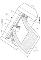
本実施形態のシートホルダー1は、図1に示すように、プロッター20がシート10に加工処理を行っている間にシート10の下敷きとして利用されるものである。
シート10は、薄葉紙からなり、具体的にはトレーシングペーパー等の比較的厚みが小さくコシのない材質から形成されたものである。
なお、シート10は、薄葉紙に限定されることなく、比較的厚みの大きい紙や合成紙、衣服用の型紙、装飾用のステンシルやマスクパターン、グリーティングカード、ペーパークラフト、フィルム、又は布等であっても良い。
As shown in FIG. 1, the
The
The
プロッター20は、カッター21の先端を選択的にシート10に圧力をかけて接触(圧接)又は離反させた状態でカッター21を保持したキャリッジ22を移動させながら、キャリッジ22の移動方向と交差する搬送方向にシート10を搬送させることで加工処理を行うものであって、カッティングプロッターに相当する。
なお、プロッター20は、シート10に所定の切断画像を形成するカッティングプロッターのほか、適宜変更可能である。例えば、カッター21の代わりにペンをキャリッジ22に保持させてシート10に所定画像を作画するペンプロッター等であっても良い。
The
The
シートホルダー1は、図1〜図3に示すように、上面にシート10が載置された状態でシート10と共に搬送方向に搬送されるシート状の基材2と、基材2上面に塗布され、粘着剤からなる複数の粘着剤ドット3と、を備えている。
基材2は、略矩形状の長尺なプラスチックシートからなり、具体的には厚さ0.1〜0.3mm程度のポリエチレンテレフタレートフィルムから形成されている。
なお、基材2は、ポリエチレンテレフタレートフィルムのほか、ポリカーボネートフィルム、紙器用板紙、白板紙、又は特殊板紙等を採用しても良い。
基材2上面は、図2に示すように、その外周縁よりも内側に所定の間隔を空けて設けられた枠線に囲まれている粘着剤塗布領域2aと、粘着剤塗布領域2aよりも外側に設けられた枠状の非粘着剤塗布領域2bと、から構成されている。
As shown in FIGS. 1 to 3, the
The
In addition to the polyethylene terephthalate film, the
As shown in FIG. 2, the upper surface of the
粘着剤塗布領域2a上には、シート10を所定位置に貼り付けるための参考ラインとなる格子ライン2cが、シート搬送方向及びキャリッジ移動方向に沿って印字されている。
非粘着剤塗布領域2b上のうち、シート搬送方向における一端部には、シート10のセッティング方向を示すための矢印マーク2dが印字されている。
なお、非粘着剤塗布領域2bのうち、シート幅方向における両端部は、それぞれ図1に示すプロッター20の加圧ローラ23と当接する部分に相当する。
On the
An
In the
粘着剤ドット3は、図2に示すように、略円形状のドットからなり、基材2上面の粘着剤塗布領域2aの全面にわたって複数塗布されている。
なお、粘着剤は、シート10を剥離可能に粘着する程度の粘着強度を有していれば良く、粘着剤の種類に依存しない。また、複数の粘着剤ドット3を所定の配置パターンで塗布するためには、例えば、基材2上面に不図示の孔空きシートを重ね合わせた上で粘着剤を噴霧することによって、基材2上面の所定位置に塗布されることになる。
As shown in FIG. 2, the
In addition, the adhesive should just have the adhesive strength of the grade which adheres the sheet |
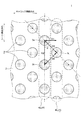
複数の粘着剤ドット3は、図2、図4に示すように、シート搬送方向に沿って所定の直径、及び所定の間隔(ピッチ)で千鳥格子状に並べられている。
具体的な数値で言うと、基材2上面の粘着剤塗布領域2a上における粘着剤ドット3の面密度は約35%〜45%が望ましく、各粘着剤ドット3の直径と間隔(ピッチ)で面密度を調整している。例えば、図4に示す粘着剤ドット3の直径を約0.9mmで間隔(ピッチ)D2を約1.83mmにすれば、面密度は約38%となる。
粘着剤ドット3の面密度の下限を約35%に設定することで、プロッター20の加工処理時にシート10に対する粘着強度を確保できる。例えばシートホルダー1が加工処理時に部分的又は全体的に傾くことがあってもシート10が浮いてしまう等の恐れが抑制される。
また、粘着剤ドット3の面密度の上限を約45%に設定することで、加工処理後には皺やカールを発生させることなくシートを容易に剥がすことができる。
なお、粘着剤ドット3の上記面密度は、上記範囲内に限定されるものではなく、粘着剤の種類によっては適宜変更されても良い。
As shown in FIGS. 2 and 4, the plurality of
More specifically, the surface density of the
By setting the lower limit of the surface density of the
In addition, by setting the upper limit of the surface density of the
In addition, the said surface density of the
次に、粘着剤ドット3の配列パターンについて図4に基づいて詳しく説明する。
粘着剤ドット3は、シート搬送方向に沿って複数並べられることで、粘着剤ドット列4を形成している。そして、粘着剤ドット列4は、キャリッジ移動方向に沿って複数並んで形成されている。
このとき、複数の粘着剤ドット列4において、互いに隣り合う2つのドット列4a、4bでは、ドット列4aを構成する各ドットの形成位置と、ドット列4bを構成する各ドットの形成位置とが、シート搬送方向において相違している。
そして、ドット列4aに共通する各粘着剤ドット3の配列と、ドット列4bに共通する各粘着剤ドット3の配列とは、キャリッジ移動方向に所定の間隔を空けて交互に並ぶパターンで形成されている。
互いに隣り合う2つのドット列4a、4bのキャリッジ移動方向における間隔D1は、粘着剤ドット列4を構成する各粘着剤ドット3のシート搬送方向における間隔D2よりも狭くなっている。
Next, the arrangement pattern of the
A plurality of the
At this time, in the plurality of
The arrangement of the
An interval D1 in the carriage movement direction between two
また、図4に示すように、ドット列4aのうち、互い隣り合う2つの粘着剤ドット3を第1ドット3a、第2ドット3bとし、ドット列4bのうち、シート搬送方向において第1ドット3aと第2ドット3bとの間に配置されるドットを第3ドット3cと設定したとする。
このとき、第1ドット3aと第3ドット3cとを結ぶ距離D3、及び第2ドット3bと第3ドット3cとを結ぶ距離D4は、それぞれ第1ドット3aと第2ドット3bとを結ぶ距離D2よりも狭くなっている。
As shown in FIG. 4, two adjacent
At this time, the distance D3 connecting the
また、図4に示すように、第1ドット3a及び第2ドット3bを通る仮想線に対する、第1ドット3a及び第3ドット3cを通る仮想線の傾斜角度をθとしたとき、傾斜角度θは約45°となるように設定されている。
上記設定により、距離D3及び距離D4は、それぞれ距離D2よりも狭くなる。すなわち、各粘着剤ドット3の傾斜方向における間隔が、シート搬送方向における間隔よりも狭くなる。
そのため、プロッター20がシート10に対してシート搬送方向とは傾斜方向に切断処理するときに、シートホルダー1がシート10を一層撓ませないように保持することができる。
通常、プロッター20がシート10に対してシート搬送方向とは傾斜方向に切断処理するときには、シート10を搬送方向に搬送しながら、同時にキャリッジ22を移動する必要があり、シート10に切削圧による最も大きい負荷が掛かることになる。従って、上記粘着剤ドット3の配列パターンが、シート10の保持力を確保する上で有意義なものとなる。
As shown in FIG. 4, when the inclination angle of the imaginary line passing through the
With the above setting, the distance D3 and the distance D4 are each narrower than the distance D2. That is, the interval in the inclination direction of each
Therefore, when the
Normally, when the
なお、傾斜角度θは、約30°以上、約60°以下に設定されていることが望ましい。このように設定されていれば、距離D3及び距離D4は、それぞれ距離D1よりも狭くなるか又は同じ長さになり、かつ、距離D2よりも狭くなるか又は同じ長さになるため、上述した粘着剤ドット3の配列パターンを実現することができる。
The inclination angle θ is preferably set to about 30 ° or more and about 60 ° or less. If set in this way, the distance D3 and the distance D4 are each smaller than or equal to the distance D1, and smaller than or equal to the distance D2, so that An arrangement pattern of the
上記構成において、シートホルダー1は、基材2上に粘着剤がドット状に複数塗布されている。そのため、基材2上の全面に粘着剤が塗布されている場合と比較して、プロッター20の加工処理時にはシート10を撓ませないように保持しながらも、加工処理後にはシート10を容易に剥がすことが可能なシートホルダーとなる。
また、シートホルダー1は、基材2上に粘着剤がシート搬送方向に沿って千鳥格子状に並べられている。そのため、例えば粘着剤が直交格子状のドットで塗布されている場合と比較して、粘着剤ドット3が一層均等な間隔で規則的に配置されることになる。従って、プロッター20の加工処理時にはシート10を一層撓ませないように保持でき、加工処理後にはシートを一層容易に剥がすことができる。
In the above configuration, the
In the
また、シートホルダー1は、上述したように粘着剤ドット3が均等な間隔で規則的に配置されている。そのため、図5に示すように、カッティングプロッターの加工処理後に、薄葉紙の一部となる比較的複雑な切断画像11を剥がす場合であっても、切断画像11の皺やカールの発生を抑え、破れることのないように薄葉紙を保持できる。
また、シートホルダー1では、図2に示すように、複数の粘着剤ドット3の一部が、粘着剤塗布領域2aと非粘着剤塗布領域2bとの境界ライン上に部分的に重なるように塗布されている。そのため、図5に示すように、当該境界ライン上に近い位置でシート10が貼りつけられた場合にも、プロッター20の加工処理時に当該シート10を撓ませないように保持することができる。
Further, as described above, the
In the
<シートホルダーの第2実施形態>
次に、シートホルダー1の第2実施例について、図6に基づいて説明する。
なお、以下の説明において上述したシートホルダー1と重複する内容は説明を省略する。
第2実施例に係るシートホルダー101では、シートホルダー1と比較して、基材102上面に設けられた粘着剤ドット103の群が、部分的に面密度が異なるように形成されている構成が異なっている。
<Second Embodiment of Sheet Holder>
Next, a second embodiment of the
In the following description, the description overlapping the above-described
In the
詳しく言うと、図6に示すように、基材102の幅方向の両端部側に配置される粘着剤ドット103の群は、中央部側に配置される粘着剤ドット103の群よりも、面密度が低くなるように形成されている。
さらに詳しく言うと、基材102の幅方向の両端部に配置される粘着剤ドット103の群は、中央部側に配置される粘着剤ドット103の群よりも、各粘着剤ドット103の直径が小さくなるように形成されている。
なお、各粘着剤ドット103の直径を調整する代わりに、各粘着剤ドット103の間隔を調整することで、上記面密度を調整しても良い。
基材102の幅方向の両端部は、それぞれ図1に示すプロッター20の加圧ローラ23と当接する部分に相当する。
More specifically, as shown in FIG. 6, the group of
More specifically, the group of the
Instead of adjusting the diameter of each pressure-
Both end portions in the width direction of the
ところで、従来のように、シートホルダー101上面において加圧ローラ23が通過する位置に粘着剤を塗布してしまうと、加圧ローラ23によってシート10が押圧されて、シート10とシートホルダー101との粘着力が強まってしまう。その結果、シートホルダー101からシート10を剥がすときにシート10に皺やカールが発生してしまう。また、シートホルダー101にシートの一部が付着してしまう。
一方で、シートホルダー101上面において加圧ローラ23が通過する位置に粘着剤を塗布しない構成とすると、シート10のサイズが比較的小さい場合には、シートホルダー101によるシート10の保持性が低下してしまう。その結果、加工処理後の仕上がりが劣ってしまう。
そこで、本実施形態では、基材102上面の両端部側と中央部側とで、粘着剤ドット103の面密度を調整することで、粘着剤の粘着強度を調整することができる。その結果、シート10の保持性を確保しながらも、加圧ローラ23の押圧によるシート10の皺やカールの発生を抑制可能なシートホルダー101となる。
By the way, if the adhesive is applied to the position where the
On the other hand, if the adhesive is not applied to the position where the
Therefore, in the present embodiment, the adhesive strength of the adhesive can be adjusted by adjusting the surface density of the
<シートホルダーの第3実施形態>
次に、シートホルダー1の第3実施例について、図7に基づいて説明する。
第3実施例に係るシートホルダー201は、シートホルダー1と比較して、基材202上面において粘着剤をドット状に塗布している領域と、粘着剤を略全面にわたって塗布している領域と、が設けられている構成が異なっている。
<Third embodiment of sheet holder>
Next, a third embodiment of the
Compared to the
詳しく言うと、図7に示すように、基材202上面のうち、シート搬送方向の一端側において粘着剤をドット状に塗布する一方で、シート搬送方向の他端側において粘着剤を略全面にわたって塗布する構成としている。
また、粘着剤の塗布領域の境目を格子ライン202cに沿わせて形成している。
上記構成により、シート10の種類に応じて、シートホルダー201上に貼り付けるシート10の位置を調整することで、シート10を所望の粘着強度で保持することが可能なシートホルダー201となる。
More specifically, as shown in FIG. 7, the adhesive is applied in the form of dots on one end side in the sheet conveying direction on the upper surface of the
Further, the boundary of the adhesive application region is formed along the
With the above configuration, by adjusting the position of the
<その他の実施形態>
上記実施形態において、図2、図4に示すように、粘着剤ドット3は、略円形状となるように形成されているが、これに限定されることなく、略楕円形状、略矩形状、略多角形状等となるように形成されていても良い。
<Other embodiments>
In the said embodiment, as shown in FIG. 2, FIG. 4, although the
また、上記実施形態において、図4に示すように、ドット列4aの各ドットの配列と、ドット列4bの各ドットの配列とが、キャリッジ移動方向に沿って交互に並ぶパターンで形成されているが、適宜変更可能である。
例えば、ドット列4a、4bの各ドットの配列が二列毎に交互に並んでいても良いし、シートホルダー1の幅方向において一端側がドット列4aの各ドットの配列で、他端側がドット列4bの各ドットの配列となっていても良い。
各粘着剤ドット列4のキャリッジ移動方向の間隔も、一定間隔で並んでいなくても良い。
In the above embodiment, as shown in FIG. 4, the
For example, the
The intervals in the carriage movement direction of the respective
また、上記実施形態において、図4に示すように、粘着剤ドット列4は、各粘着剤ドット3がシート搬送方向に所定の間隔を空けて並ぶように構成されているが、これに限定されることなく、各粘着剤ドット3の間隔が、一定間隔で並んでいなくても良い。
Moreover, in the said embodiment, as shown in FIG. 4, although the adhesive dot row | line |
また、上記実施形態において、図1に示すように、プロッター20では、シート搬送方向と、キャリッジ移動方向とが互いに直交するように構成されているが、シート搬送方向と、キャリッジ移動方向とが互いに交差するように構成されていれば良い。
In the above embodiment, as shown in FIG. 1, the
また、上記実施形態において、図1に示すように、プロッター20では、キャリッジ22にカッター21を保持させた構成となっているが、当該キャリッジ22にカッター21及びペンの両方を保持させる構成として、カッター及びペンの両方の機能を備えたプロッターとしても良い。
In the above embodiment, as shown in FIG. 1, the
本実施形態では、主として本発明に係るシートホルダーに関して説明した。ただし、上記の実施形態は、本発明の理解を容易にするための一例に過ぎず、本発明を限定するものではない。本発明は、その趣旨を逸脱することなく、変更、改良され得ると共に、本発明にはその等価物が含まれることは勿論である。
特に、シートホルダー1の粘着剤ドット3の配置パターンついて、上記の実施形態にて説明したものは、あくまで一例に過ぎず、本発明を限定するものではない。
In the present embodiment, the seat holder according to the present invention has been mainly described. However, said embodiment is only an example for making an understanding of this invention easy, and does not limit this invention. The present invention can be changed and improved without departing from the gist thereof, and the present invention includes the equivalents thereof.
In particular, the arrangement pattern of the
1、101、201 シートホルダー
2、102、202 基材
2a 粘着剤塗布領域
2b 非粘着剤塗布領域
2c、202c 格子ライン
2d 矢印マーク
3、103 粘着剤ドット
3a 第1ドット
3b 第2ドット
3c 第3ドット
4 粘着剤ドット列
4a ドット列
4b ドット列
10 シート
11 切断画像
20 プロッター
21 カッター
22 キャリッジ
23 加圧ローラ
D1、D2、D3、D4 距離(間隔)
θ 傾斜角度
1, 101, 201
θ Inclination angle
Claims (6)
上面に前記シートが載置された状態で前記シートと共に前記搬送方向に搬送されるシート状の前記基材と、
該基材上面に形成され、粘着剤からなるドットが前記搬送方向に沿って複数並んで構成される粘着剤ドット列と、を備え、
該粘着剤ドット列は、前記移動方向に沿って複数並んで形成されており、
複数の前記粘着剤ドット列中、互いに隣り合う2つの前記粘着剤ドット列のうち、一方の前記粘着剤ドット列を構成する各前記ドットの形成位置と、他方の前記粘着剤ドット列を構成する各前記ドットの形成位置とが、前記搬送方向において相違しており、
前記ドットは、前記基材上面に複数設けられてドット群を形成し、
該ドット群のうち、前記移動方向における前記基材の前記両端部側であって前記加圧ローラが通過する位置に配置される前記ドット群は、中央部側に配置される前記ドット群よりも、面密度が低くなるように形成されていることを特徴とするシートホルダー。 The tip of a pen or a cutter while in contact or separated by applying pressure to the sheet, Rutotomoni move the carriage holding the pen or cutter, the both end portions in the width direction of the base for placing the sheet pressure while pressing at pressure roller, a sheet holder for use in a plotter for performing processing by which convey the sheet in the transport direction intersecting the movement direction of the carriage,
A sheet-like of the substrate to be transported in the transport direction together with the sheet in a state in which the sheet is placed on the upper surface,
An adhesive dot row formed on the upper surface of the base material and formed of a plurality of dots made of an adhesive along the transport direction; and
The adhesive dot row is formed in a plurality along the moving direction,
Among the plurality of adhesive dot rows, among the two adhesive dot rows adjacent to each other, the formation position of each dot constituting one of the adhesive dot rows and the other adhesive dot row are constituted. The formation position of each dot is different in the transport direction ,
A plurality of the dots are provided on the upper surface of the base material to form a dot group,
Among the dot groups, the dot group disposed at the position where the pressure roller passes on both ends of the base material in the moving direction is more than the dot group disposed on the center side. The sheet holder is formed so as to have a low surface density .
前記一方の粘着剤ドット列に共通する各前記ドットの配列と、前記他方の粘着剤ドット列に共通する各前記ドットの配列とが、前記移動方向に所定の間隔を空けて交互に並ぶように形成されていることを特徴とする請求項1に記載のシートホルダー。 A plurality of the adhesive dot rows are
The dot arrangement common to the one adhesive dot row and the dot arrangement common to the other adhesive dot row are alternately arranged at a predetermined interval in the movement direction. The sheet holder according to claim 1, wherein the sheet holder is formed.
互いに隣り合う2つの前記粘着剤ドット列の前記移動方向における間隔が、前記粘着剤ドット列を構成する各前記ドットの前記搬送方向における間隔よりも狭くなっていることを特徴とする請求項2に記載のシートホルダー。 The adhesive dot row is configured such that each dot has a predetermined interval in the transport direction,
The distance in the moving direction between the two adhesive dot rows adjacent to each other is narrower than the interval in the transport direction of the dots constituting the adhesive dot row. The described seat holder.
前記他方の粘着剤ドット列のうち、前記搬送方向において前記第1ドットと前記第2ドットとの間に配置される第3ドットと、を備え、
前記第1ドット及び前記第2ドットと、前記第3ドットとをそれぞれ結ぶ距離が、前記第1ドットと前記第2ドットとを結ぶ距離よりも狭くなっていることを特徴とする請求項1乃至3のいずれか1項に記載のシートホルダー。 Among the one adhesive dot row, the first dot and the second dot adjacent to each other,
A third dot disposed between the first dot and the second dot in the transport direction in the other adhesive dot row;
The distance connecting the first dot, the second dot, and the third dot is smaller than the distance connecting the first dot and the second dot, respectively. The sheet holder according to any one of 3.
円形状となるように形成され、前記搬送方向に沿って所定の直径及び間隔で千鳥格子状に並んでおり、
前記第1ドット及び前記第2ドットを通る仮想線に対する、前記第1ドット及び前記第3ドットを通る仮想線の傾斜角度θが、30°≦θ≦60°となるように並んでいることを特徴とする請求項4に記載のシートホルダー。 Each dot is
It is formed in a circular shape, and is arranged in a staggered pattern with a predetermined diameter and spacing along the transport direction,
The inclination angle θ of the imaginary line passing through the first dot and the third dot with respect to the imaginary line passing through the first dot and the second dot is arranged so that 30 ° ≦ θ ≦ 60 °. The sheet holder according to claim 4, wherein
Priority Applications (3)
| Application Number | Priority Date | Filing Date | Title |
|---|---|---|---|
| JP2014069589A JP6325309B2 (en) | 2014-03-28 | 2014-03-28 | Seat holder |
| US14/670,337 US20150273717A1 (en) | 2014-03-28 | 2015-03-26 | Sheet holder |
| EP15161342.9A EP2923854B1 (en) | 2014-03-28 | 2015-03-27 | Sheet holder |
Applications Claiming Priority (1)
| Application Number | Priority Date | Filing Date | Title |
|---|---|---|---|
| JP2014069589A JP6325309B2 (en) | 2014-03-28 | 2014-03-28 | Seat holder |
Publications (2)
| Publication Number | Publication Date |
|---|---|
| JP2015188985A JP2015188985A (en) | 2015-11-02 |
| JP6325309B2 true JP6325309B2 (en) | 2018-05-16 |
Family
ID=52807633
Family Applications (1)
| Application Number | Title | Priority Date | Filing Date |
|---|---|---|---|
| JP2014069589A Active JP6325309B2 (en) | 2014-03-28 | 2014-03-28 | Seat holder |
Country Status (3)
| Country | Link |
|---|---|
| US (1) | US20150273717A1 (en) |
| EP (1) | EP2923854B1 (en) |
| JP (1) | JP6325309B2 (en) |
Families Citing this family (4)
| Publication number | Priority date | Publication date | Assignee | Title |
|---|---|---|---|---|
| KR101771567B1 (en) | 2017-01-26 | 2017-09-05 | 주식회사 가야 | Adhesive film with no tunneling and manufacturing method of the same |
| CN108968361A (en) * | 2018-07-30 | 2018-12-11 | 佛山市缘懿科技有限公司 | A kind of indoor designing drawing device |
| JP2020113181A (en) * | 2019-01-16 | 2020-07-27 | ブラザー工業株式会社 | Positioning jig |
| CN110744626B (en) * | 2019-11-04 | 2021-04-13 | 徐州协盈电子科技有限公司 | Semiconductor shading film die-cutting mechanism |
Family Cites Families (16)
| Publication number | Priority date | Publication date | Assignee | Title |
|---|---|---|---|---|
| US3384964A (en) * | 1966-06-06 | 1968-05-28 | Robert E. Phillips | Sketching device |
| DE6810058U (en) * | 1968-12-05 | 1969-03-27 | Hans Silberhorn Fa | WRITING PAD |
| AT358952B (en) * | 1978-02-10 | 1980-10-10 | Irrgeher Hans | DRAWING BASE WITH AN ORTHOGONAL GRID |
| JPH02155799A (en) * | 1988-12-09 | 1990-06-14 | Abisare:Kk | Reinforcement sheet for drawing paper of plotter |
| JPH0489396U (en) * | 1990-09-28 | 1992-08-04 | ||
| JPH04201099A (en) * | 1990-11-29 | 1992-07-22 | Roland D G Kk | Film for fixing material to be worked |
| JPH0569695A (en) * | 1991-09-13 | 1993-03-23 | Roland D G Kk | Lining sheet material for plotter and its manufacture |
| DE19950246A1 (en) * | 1999-10-19 | 2001-04-26 | Walter Schlutius | Over large support with associated positioning markings for holding a smaller sheet so that it can be printed up to its edges, the support including an adhesive area to which the sheet to be printed is attached to |
| US20050189066A1 (en) * | 2003-10-27 | 2005-09-01 | Tom Look | Laminated cards and methods of manufacture for secure applications |
| DE20319443U1 (en) * | 2003-12-15 | 2004-11-11 | helit innovative Büroprodukte GmbH | Organiser element for desktop accessories comprises function plate with recesses in axial directions to correspond with lower design of accessories |
| JP2005205539A (en) * | 2004-01-22 | 2005-08-04 | Graphtec Corp | Cutting object medium driving type cutting plotter |
| JP2005205540A (en) * | 2004-01-22 | 2005-08-04 | Graphtec Corp | Cutting object medium support sheet of cutting object medium driving type cutting plotter |
| JP2012213846A (en) * | 2011-03-30 | 2012-11-08 | Brother Industries Ltd | Cutting device and holding member |
| JP5327261B2 (en) * | 2011-03-30 | 2013-10-30 | ブラザー工業株式会社 | Cutting device |
| JP2013144343A (en) * | 2012-01-16 | 2013-07-25 | Brother Industries Ltd | Cutting device |
| JP2013178306A (en) * | 2012-02-28 | 2013-09-09 | Seiko Instruments Inc | Adhesive label and label issuance apparatus |
-
2014
- 2014-03-28 JP JP2014069589A patent/JP6325309B2/en active Active
-
2015
- 2015-03-26 US US14/670,337 patent/US20150273717A1/en not_active Abandoned
- 2015-03-27 EP EP15161342.9A patent/EP2923854B1/en active Active
Also Published As
| Publication number | Publication date |
|---|---|
| EP2923854A1 (en) | 2015-09-30 |
| US20150273717A1 (en) | 2015-10-01 |
| EP2923854B1 (en) | 2019-12-18 |
| JP2015188985A (en) | 2015-11-02 |
Similar Documents
| Publication | Publication Date | Title |
|---|---|---|
| JP6325309B2 (en) | Seat holder | |
| JP2010052432A (en) | Method and apparatus for manufacturing stack for forming book block | |
| JP5800230B2 (en) | Thermal transfer system and thermal transfer method, winding device and winding method | |
| JP5286552B2 (en) | Adhesive piece of paper | |
| JP5782935B2 (en) | Slip | |
| JPWO2017150386A1 (en) | Peelable laminate | |
| KR101964102B1 (en) | Label assembly | |
| US9852661B2 (en) | Self laminating labels | |
| JP5617377B2 (en) | Delivery slip with candy | |
| JP6351966B2 (en) | CONTINUOUS LABEL SHEET, METHOD FOR PRODUCING CONTINUOUS LABEL SHEET, AND METHOD FOR Peeling Label From Continuous Label Sheet And Affixing To Substrate | |
| JP4855817B2 (en) | Label sheet | |
| JP2013049818A (en) | Adhesive sheet and method for producing the same | |
| JP2016153857A (en) | Label sheet | |
| WO2014110079A1 (en) | Multi-die cut with common axis | |
| JP5117751B2 (en) | Seal sheet | |
| JP2013028050A (en) | Re-peelable overlapped sheet | |
| JP6988072B2 (en) | Delivery slip | |
| JP3200770U (en) | Sheet composite, sheet holder, printing sheet and printed matter | |
| US20030025920A1 (en) | Printable media for use in multi-sheet assemblies | |
| JP3123335U (en) | Paper | |
| JP6988073B2 (en) | Delivery slip | |
| JP6798175B2 (en) | Manufacturing method of printed matter with card paper and printed matter with card paper | |
| WO2014122801A1 (en) | Label | |
| JP6121773B6 (en) | label | |
| JP5845770B2 (en) | Continuous form laminate |
Legal Events
| Date | Code | Title | Description |
|---|---|---|---|
| A621 | Written request for application examination |
Free format text: JAPANESE INTERMEDIATE CODE: A621 Effective date: 20161221 |
|
| A977 | Report on retrieval |
Free format text: JAPANESE INTERMEDIATE CODE: A971007 Effective date: 20171026 |
|
| A131 | Notification of reasons for refusal |
Free format text: JAPANESE INTERMEDIATE CODE: A131 Effective date: 20171031 |
|
| A601 | Written request for extension of time |
Free format text: JAPANESE INTERMEDIATE CODE: A601 Effective date: 20171227 |
|
| A521 | Request for written amendment filed |
Free format text: JAPANESE INTERMEDIATE CODE: A523 Effective date: 20180227 |
|
| TRDD | Decision of grant or rejection written | ||
| A01 | Written decision to grant a patent or to grant a registration (utility model) |
Free format text: JAPANESE INTERMEDIATE CODE: A01 Effective date: 20180320 |
|
| A61 | First payment of annual fees (during grant procedure) |
Free format text: JAPANESE INTERMEDIATE CODE: A61 Effective date: 20180412 |
|
| R150 | Certificate of patent or registration of utility model |
Ref document number: 6325309 Country of ref document: JP Free format text: JAPANESE INTERMEDIATE CODE: R150 |
|
| R250 | Receipt of annual fees |
Free format text: JAPANESE INTERMEDIATE CODE: R250 |
|
| R250 | Receipt of annual fees |
Free format text: JAPANESE INTERMEDIATE CODE: R250 |
|
| R250 | Receipt of annual fees |
Free format text: JAPANESE INTERMEDIATE CODE: R250 |
|
| S111 | Request for change of ownership or part of ownership |
Free format text: JAPANESE INTERMEDIATE CODE: R313113 |
|
| R371 | Transfer withdrawn |
Free format text: JAPANESE INTERMEDIATE CODE: R371 |
|
| S111 | Request for change of ownership or part of ownership |
Free format text: JAPANESE INTERMEDIATE CODE: R313113 |
|
| R350 | Written notification of registration of transfer |
Free format text: JAPANESE INTERMEDIATE CODE: R350 |
|
| R250 | Receipt of annual fees |
Free format text: JAPANESE INTERMEDIATE CODE: R250 |