CN110744626B - Semiconductor shading film die-cutting mechanism - Google Patents
Semiconductor shading film die-cutting mechanism Download PDFInfo
- Publication number
- CN110744626B CN110744626B CN201911063872.1A CN201911063872A CN110744626B CN 110744626 B CN110744626 B CN 110744626B CN 201911063872 A CN201911063872 A CN 201911063872A CN 110744626 B CN110744626 B CN 110744626B
- Authority
- CN
- China
- Prior art keywords
- fixedly connected
- fixed
- bottom plate
- side wall
- connecting block
- Prior art date
- Legal status (The legal status is an assumption and is not a legal conclusion. Google has not performed a legal analysis and makes no representation as to the accuracy of the status listed.)
- Expired - Fee Related
Links
Images


Classifications
-
- B—PERFORMING OPERATIONS; TRANSPORTING
- B26—HAND CUTTING TOOLS; CUTTING; SEVERING
- B26F—PERFORATING; PUNCHING; CUTTING-OUT; STAMPING-OUT; SEVERING BY MEANS OTHER THAN CUTTING
- B26F1/00—Perforating; Punching; Cutting-out; Stamping-out; Apparatus therefor
- B26F1/38—Cutting-out; Stamping-out
- B26F1/384—Cutting-out; Stamping-out using rotating drums
-
- B—PERFORMING OPERATIONS; TRANSPORTING
- B26—HAND CUTTING TOOLS; CUTTING; SEVERING
- B26D—CUTTING; DETAILS COMMON TO MACHINES FOR PERFORATING, PUNCHING, CUTTING-OUT, STAMPING-OUT OR SEVERING
- B26D7/00—Details of apparatus for cutting, cutting-out, stamping-out, punching, perforating, or severing by means other than cutting
- B26D7/01—Means for holding or positioning work
- B26D7/02—Means for holding or positioning work with clamping means
-
- B—PERFORMING OPERATIONS; TRANSPORTING
- B26—HAND CUTTING TOOLS; CUTTING; SEVERING
- B26D—CUTTING; DETAILS COMMON TO MACHINES FOR PERFORATING, PUNCHING, CUTTING-OUT, STAMPING-OUT OR SEVERING
- B26D7/00—Details of apparatus for cutting, cutting-out, stamping-out, punching, perforating, or severing by means other than cutting
- B26D7/18—Means for removing cut-out material or waste
- B26D7/1845—Means for removing cut-out material or waste by non mechanical means
- B26D7/1854—Means for removing cut-out material or waste by non mechanical means by air under pressure
Abstract
The invention discloses a semiconductor shading film die-cutting mechanism which comprises a bottom plate shell, a first electric push rod, a first rotating motor, a fixed groove, a second electric push rod, a crawler belt, a limiting plate, a fixed support shell, a first connecting block, a first sliding block, a telescopic connecting rod, a second connecting block, a second sliding block, a roller, a supporting rod, a second rotating motor, a die-cutting roller, a rotating connecting shaft, a gear, a wind dispersing plate, a fan, a collecting box and a collecting groove. The invention has the beneficial effects that: the shading film that this device was treated processing through fixed indent structure compresses tightly fixedly, through the distance between the fixed indent structure of adjustment, can all compress tightly fixedly to the shading film of different length, prevents when compressing tightly fixedly that the shading film from taking place the skew and folding man-hour adding, improves the precision of processing.
Description
Technical Field
The invention relates to a die-cutting mechanism, in particular to a semiconductor shading film die-cutting mechanism, and belongs to the technical field of application of instrument shading film die-cutting mechanisms.
Background
The die cutting mechanism is mainly used for die cutting (full-break and half-break), indentation and gold stamping operation, fitting and automatic waste discharge of corresponding non-metal materials, non-setting adhesives, EVA (ethylene vinyl acetate), double faced adhesive tapes, electronics, mobile phone rubber mats and the like, and the die cutting machine applies certain pressure through a steel knife, a hardware die and a steel wire (or a template carved by a steel plate) and rolls and cuts a print or a paperboard into a certain shape through a stamping plate. Is an important device for processing and forming the packages after printing.
Semiconductor shading film need fix the film when carrying out cross cutting processing, because of film self surface is comparatively smooth, and the easy misoperation leads to the raw materials skew during cross cutting processing, leads to the finished product of processing unqualifiedly. Therefore, a semiconductor light-shielding film die-cutting mechanism is provided to solve the above problems.
Disclosure of Invention
The invention aims to solve the problems and provide a die cutting mechanism for a semiconductor light-shielding film.
The invention achieves the aim through the following technical scheme, and the semiconductor shading film die-cutting mechanism comprises a bottom plate shell, a die-cutting roller, a fixed pressure groove structure and a finished product collecting structure, wherein a second sliding block is connected inside the bottom plate shell in a sliding manner, one end of a first electric push rod is fixedly connected to the side wall of an inner cavity of the bottom plate shell, the other end of the first electric push rod is fixedly connected to the side wall of the inner cavity of the bottom plate shell, one end of a second connecting block is fixedly connected to the upper surface of the second sliding block, the other end of the second connecting block penetrates through the side wall of the inner cavity of the bottom plate shell and extends out of the inner cavity, the side walls of two ends of the bottom plate shell are fixedly connected with second electric push rods, the other ends of the two second electric push rods are fixedly connected with a fixed supporting shell, the fixed pressure groove structures on the bottom plate shell and the fixed supporting shell are in a straight line in the vertical direction, the fixed pressure groove structures on the first connecting block and the, a first sliding block is connected in an inner cavity of the fixed supporting shell in a sliding manner, the lower surface of the first sliding block is fixedly connected with one end of a first connecting block, the other end of the first connecting block penetrates through the side wall of the fixed supporting shell and extends out of the wall, and a fixed pressure groove structure is fixedly arranged on the upper surface of the bottom plate shell, the lower surface of the fixed supporting shell, one end of the second connecting block and one end of the first connecting block;
the fixed pressure groove structure comprises a fixed groove, a crawler and rollers, the side wall of the inner cavity of the fixed groove is rotatably connected with a plurality of rollers, a crawler belt is fixedly sleeved between the rollers, the upper surface of the bottom plate shell is fixedly connected with a first rotating motor, the tail end of the output shaft of the first rotating motor penetrates through the side wall of the fixing groove and extends to the side wall of the roller, a telescopic connecting rod is fixedly connected between the side walls of the two fixing grooves on the second connecting block and the first connecting block, the arc surface of the second electric push rod and the side surface of the telescopic connecting rod are both fixedly connected with a limiting plate, the two telescopic connecting rods are in a straight line in the horizontal direction, the side wall of the telescopic connecting rod is fixedly connected with another first rotating motor, and the tail end of an output shaft of the other first rotating motor penetrates through the side walls of the telescopic connecting rod and the fixing groove and extends to the side wall of the roller;
the two ends of the upper surface of the bottom plate shell are fixedly connected with supporting rods, the two supporting rods are rotatably connected with two die cutting rollers through rotating connecting shafts, the side walls of the supporting rods are fixedly connected with second rotating motors, and the tail ends of output shafts of the second rotating motors penetrate through the side walls of the supporting rods and are connected with the rotating connecting shafts;
the upper surface of the bottom plate shell is fixedly provided with a finished product collecting structure, the finished product collecting structure comprises an air dispersing plate, a fan, a collecting box and a collecting groove, the air dispersing plate is fixedly connected in an inner cavity of the collecting box, the collecting groove is inserted into the lower surface of the inner cavity of the collecting box, the fan is fixedly connected to the upper surface of the collecting box, and an output end of the fan penetrates through the side wall of the collecting box and extends to be fixed to the air dispersing plate.
Preferably, one end of each of the two rotating connecting shafts is fixedly connected with a gear, and the gears are meshed with each other.
Preferably, the interior of the air diffuser plate is of a cavity structure, and a plurality of vent holes are formed in the lower wall of the cavity of the air diffuser plate.
Preferably, the side wall of the collecting box is provided with a rectangular through hole.
The invention has the beneficial effects that:
1. the shading film that this device was treated processing through fixed indent structure compresses tightly fixedly, through the distance between the fixed indent structure of adjustment, can all compress tightly fixedly to the shading film of different length, prevents when compressing tightly fixedly that the shading film from taking place the skew and folding man-hour adding, improves the precision of processing.
2. This device collects the structure through the finished product and separates and collect the finished product that processing finishes, separates leftover bits and finished product on the one hand, and on the other hand collects the finished product, prevents the trouble of artifical collection after the finished product processing, avoids the shading film to cut out the back simultaneously and does not in time collect and lead to dropping and losing.
Drawings
In order to more clearly illustrate the embodiments of the present invention or the technical solutions in the prior art, the drawings used in the description of the embodiments or the prior art will be briefly described below, and it is obvious that the drawings in the following description are only some embodiments of the present invention, and for those skilled in the art, other drawings can be obtained according to these drawings without inventive exercise.
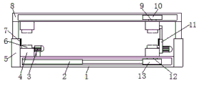
FIG. 1 is a schematic perspective view of the present invention;
FIG. 2 is a schematic view of the connection structure of the fixed indent structure of the present invention;
FIG. 3 is a schematic view showing a coupling structure of the die-cutting roll according to the present invention;
FIG. 4 is a schematic view of the internal structure of the finished product collection structure of the present invention;
FIG. 5 is a schematic view of the internal structure of the fixed indent structure of the present invention.
In the figure: 1. the bottom plate shell, 2, first electric putter, 3, first rotation motor, 4, the fixed slot, 5, second electric putter, 6, the track, 7, the limiting plate, 8, the fixed bolster shell, 9, first connecting block, 10, first slider, 11, telescopic link, 12, the second connecting block, 13, the second slider, 14, the gyro wheel, 15, the bracing piece, 16, the second rotates the motor, 17, the die-cutting roller, 18, rotates the connecting axle, 19, the gear, 20, the board that looses, 21, the fan, 22, the collecting box, 23, the collecting vat.
Detailed Description
In order to make the objects, features and advantages of the present invention more obvious and understandable, the technical solutions in the embodiments of the present invention will be clearly and completely described below with reference to the accompanying drawings in the embodiments of the present invention, and it is obvious that the embodiments described below are only a part of the embodiments of the present invention, and not all of the embodiments. All other embodiments, which can be derived by a person skilled in the art from the embodiments given herein without making any creative effort, shall fall within the protection scope of the present invention.
The technical scheme of the invention is further explained by the specific implementation mode in combination with the attached drawings.
In the description of the present invention, it is to be understood that the terms "upper", "lower", "top", "bottom", "inner", "outer", and the like, indicate orientations or positional relationships based on those shown in the drawings, and are used only for convenience in describing the present invention and for simplicity in description, and do not indicate or imply that the referenced devices or elements must have a particular orientation, be constructed and operated in a particular orientation, and thus, are not to be construed as limiting the present invention.
Referring to fig. 1-5, a semiconductor light-shielding film die-cutting mechanism comprises a bottom plate shell 1, a die-cutting roller 17, a fixed pressure groove structure and a finished product collecting structure, wherein a second slider 13 is slidably connected inside the bottom plate shell 1, one end of a first electric push rod 2 is fixedly connected to the side wall of the second slider 13, the other end of the first electric push rod 2 is fixedly connected to the side wall of the inner cavity of the bottom plate shell 1, one end of a second connecting block 12 is fixedly connected to the upper surface of the second slider 13, the other end of the second connecting block 12 penetrates through the side wall of the inner cavity of the bottom plate shell 1 and extends out of the inner cavity, the side walls of the two ends of the bottom plate shell 1 are fixedly connected with second electric push rods 5, the other ends of the two second electric push rods 5 are fixedly connected with a fixed support shell 8, and the fixed pressure groove structures on the bottom plate shell 1 and the fixed support shell 8 are in a, the fixed pressure groove structures on the first connecting block 9 and the second connecting block 12 are in a straight line in the vertical direction, a first sliding block 10 is connected in an inner cavity of the fixed supporting shell 8 in a sliding mode, the lower surface of the first sliding block 10 is fixedly connected with one end of the first connecting block 9, the other end of the first connecting block 9 penetrates through the side wall of the fixed supporting shell 8 and extends out of the wall, and the fixed pressure groove structures are fixedly arranged on the upper surface of the bottom plate shell 1, the lower surface of the fixed supporting shell 8, one end of the second connecting block 12 and one end of the first connecting block 9;
the fixed pressure groove structure comprises a fixed groove 4, a crawler 6 and a roller 14, the inner cavity side wall of the fixed groove 4 is rotatably connected with a plurality of rollers 14, the crawler 6 is fixedly sleeved between the rollers 14 and the rollers 14, the upper surface of the bottom plate shell 1 is fixedly connected with a first rotating motor 3, the tail end of an output shaft of the first rotating motor 3 penetrates through the side wall of the fixed groove 4 and extends to the side wall of the roller 14, a telescopic connecting rod 11 is fixedly connected between the side walls of the two fixed grooves 4 on the second connecting block 12 and the first connecting block 9, the fixed pressure groove structures on the bottom plate shell 1 and the fixed supporting shell 8 are a straight line in the vertical direction, the fixed pressure groove structures on the first connecting block 9 and the second connecting block 12 are a straight line in the vertical direction, and the side wall of the telescopic connecting rod 11 is fixedly connected with another first rotating motor 3, the tail end of the output shaft of the other first rotating motor 3 penetrates through the telescopic connecting rod 11 and the side wall of the fixed groove 4 and extends to the side wall of the roller 14;
the two ends of the upper surface of the bottom plate shell 1 are fixedly connected with supporting rods 15, the two supporting rods 15 are rotatably connected with two die cutting rollers 17 through rotating connecting shafts 18, the side walls of the supporting rods 15 are fixedly connected with second rotating motors 16, and the tail ends of output shafts of the second rotating motors 16 penetrate through the side walls of the supporting rods 15 and are connected with the rotating connecting shafts 18;
the upper surface of the bottom plate shell 1 is fixedly provided with a finished product collecting structure, the finished product collecting structure comprises an air diffuser plate 20, a fan 21, a collecting box 22 and a collecting groove 23, the air diffuser plate 20 is fixedly connected in an inner cavity of the collecting box 22, the collecting groove 23 is inserted into the lower surface of the inner cavity of the collecting box 22, the fan 21 is fixedly connected to the upper surface of the collecting box 22, and an output end of the fan 21 penetrates through the side wall of the collecting box 22 and extends and is fixed to the air diffuser plate 20.
One end of each of the two rotating connecting shafts 18 is fixedly connected with a gear 19, and the two gears 19 are meshed with each other; the interior of the air diffuser plate 20 is of a cavity structure, and the lower wall of the cavity of the air diffuser plate 20 is provided with a plurality of vent holes; the side wall of the collecting box 22 is provided with a rectangular through hole.
When the device is used, firstly, the distance between the fixed pressure groove structures is adjusted according to the length of a film to be processed, the fixed pressure groove structures are driven to move by starting the switch adjustment of the first electric push rod 2 to achieve the purpose of adjusting the distance, then the film to be processed is placed on the crawler belts 6 of the two fixed pressure groove structures, then the fixed pressure groove structures are driven to move by the contraction of the first electric push rod 2, the telescopic connecting rod 11 is driven to move by the movement of the fixed pressure groove structures, the limiting plates 7 are driven to move by the telescopic connecting rod 11, the film is enabled to face the die cutting roller 17 by the mutual clamping between the two limiting plates 7 to prevent the film from deviating, then the switches of the two second electric push rods 5 are started, the fixed pressure groove structures are enabled to be mutually clamped by the contraction of the two second electric push rods 5, and the film is fixed by the clamping between the fixed pressure groove structures, the film is prevented from being folded during processing, the first rotating motors 3 drive the rollers 14 to rotate by starting the switches of the two first rotating motors 3, the track 6 is driven to move by the roller 14, the film is driven to move by the movement of the track 6, then the switch of the second rotating motor 16 is started, the second rotating motor 16 drives the two die-cutting rollers 17 to rotate, the film is processed by die cutting through the rotation of the die cutting roller 17, the die-cut film enters the inner cavity of the collecting box 22 through the rectangular through hole of the collecting box 22, then the switch of the fan 21 is started, the air blown out by the fan 21 enters the air diffuser 20 and then is blown to the processed film, blowing down the processed finished rubber sheets by blowing air, blowing the processed finished rubber sheets into the collecting tank 23, leaving the leftover materials after die cutting, thus, the finished product and the leftover material are separated, and then the worker can take out the finished product by pumping out the collecting tank 23.
The first electric push rod 2 is an electric push rod of LEC606 model manufactured by Suzhou Yuancheng Ming Chuang electromechanical equipment Limited company and a related matched power supply and circuit thereof.
The first rotating motor 3 adopts a motor of TC7116 model produced by Shenzhen Xintai motor Limited and a related matched power supply and circuit thereof.
The second electric push rod 5 adopts an electric push rod of 2068-50 product number produced by the Fuji electronic technology Limited company in Zhongshan City and a related matched power supply and circuit thereof.
The second rotating motor 16 is a motor of TC7116 model produced by Shenzhen Xintai motor Limited and its related power supply and circuit.
The blower 21 adopts a WM145160-24V type blower produced by Ningbo Fenghuai Weicheng motor factory, a related power supply and a related circuit thereof.
It will be evident to those skilled in the art that the invention is not limited to the details of the foregoing illustrative embodiments, and that the present invention may be embodied in other specific forms without departing from the spirit or essential attributes thereof. The present embodiments are therefore to be considered in all respects as illustrative and not restrictive, the scope of the invention being indicated by the appended claims rather than by the foregoing description, and all changes which come within the meaning and range of equivalency of the claims are therefore intended to be embraced therein. Any reference sign in a claim should not be construed as limiting the claim concerned.
The above-mentioned embodiments are only used for illustrating the technical solutions of the present invention, and not for limiting the same; although the present invention has been described in detail with reference to the foregoing embodiments, it will be understood by those of ordinary skill in the art that: the technical solutions described in the foregoing embodiments may still be modified, or some technical features may be equivalently replaced; and such modifications or substitutions do not depart from the spirit and scope of the corresponding technical solutions of the embodiments of the present invention.
Claims (4)
1. The utility model provides a semiconductor shading film die-cutting mechanism which characterized in that: the die-cutting machine comprises a bottom plate shell (1), die-cutting rollers (17), a fixed pressure groove structure and a finished product collecting structure, wherein a second sliding block (13) is connected to the inner part of the bottom plate shell (1) in a sliding manner, one end of a first electric push rod (2) is fixedly connected to the side wall of the second sliding block (13), the other end of the first electric push rod (2) is fixedly connected to the side wall of the inner cavity of the bottom plate shell (1), one end of a second connecting block (12) is fixedly connected to the upper surface of the second sliding block (13), the other end of the second connecting block (12) penetrates through the side wall of the inner cavity of the bottom plate shell (1) and extends out of the inner cavity, the side walls of the two ends of the bottom plate shell (1) are fixedly connected with second electric push rods (5), the other ends of the two second electric push rods (5) are fixedly connected with a fixed supporting shell (8), and the fixed pressure groove structures on the bottom plate shell (1), a first sliding block (10) is connected in an inner cavity of the fixed supporting shell (8) in a sliding mode, the lower surface of the first sliding block (10) is fixedly connected with one end of a first connecting block (9), the other end of the first connecting block (9) penetrates through the side wall of the fixed supporting shell (8) and extends out of the wall, fixed pressure groove structures are fixedly arranged on the upper surface of the bottom plate shell (1), the lower surface of the fixed supporting shell (8), one end of a second connecting block (12) and one end of the first connecting block (9), and the fixed pressure groove structures on the first connecting block (9) and the second connecting block (12) are in a straight line in the vertical direction;
the fixed pressure groove structure comprises a fixed groove (4), a track (6) and rollers (14), wherein the inner cavity side wall of the fixed groove (4) is rotatably connected with a plurality of rollers (14), the track (6) is fixedly sleeved between the rollers (14) and the rollers (14), the upper surface of the bottom plate shell (1) is fixedly connected with a first rotating motor (3), the tail end of an output shaft of the first rotating motor (3) penetrates through the side wall of the fixed groove (4) and extends to the side wall of the rollers (14), a telescopic connecting rod (11) is fixedly connected between the second connecting block (12) and the side walls of the two fixed grooves (4) on the first connecting block (9), a limiting plate (7) is fixedly connected on the arc-shaped surface of the second electric push rod (5) and the side surface of the telescopic connecting rod (11), and the telescopic connecting rod (11) is a straight line in the horizontal direction, the side wall of the telescopic connecting rod (11) is fixedly connected with another first rotating motor (3), and the tail end of an output shaft of the another first rotating motor (3) penetrates through the side walls of the telescopic connecting rod (11) and the fixing groove (4) and extends to the side wall of the roller (14);
the two ends of the upper surface of the bottom plate shell (1) are fixedly connected with supporting rods (15), the two supporting rods (15) are rotatably connected with two die cutting rollers (17) through rotating connecting shafts (18), the side walls of the supporting rods (15) are fixedly connected with second rotating motors (16), and the tail ends of output shafts of the second rotating motors (16) penetrate through the side walls of the supporting rods (15) and are connected with the rotating connecting shafts (18);
the upper surface fixed mounting of bottom plate shell (1) has the finished product to collect the structure, the finished product is collected the structure and is included air diffuser (20), fan (21), collecting box (22) and collecting vat (23), fixedly connected with air diffuser (20) in the inner chamber of collecting box (22), peg graft and have collecting vat (23) on the inner chamber lower surface of collecting box (22), the upper surface fixed connection of collecting box (22) has fan (21), the output of fan (21) runs through the lateral wall of collecting box (22) and extends and fix to air diffuser (20) on.
2. The semiconductor light-shielding film die-cutting mechanism according to claim 1, wherein: one end of each of the two rotating connecting shafts (18) is fixedly connected with a gear (19), and the two gears (19) are meshed with each other.
3. The semiconductor light-shielding film die-cutting mechanism according to claim 1, wherein: the interior of the air diffuser plate (20) is of a cavity structure, and a plurality of vent holes are formed in the lower wall of the cavity of the air diffuser plate (20).
4. The semiconductor light-shielding film die-cutting mechanism according to claim 1, wherein: the side wall of the collecting box (22) is provided with a rectangular through hole.
Priority Applications (1)
| Application Number | Priority Date | Filing Date | Title |
|---|---|---|---|
| CN201911063872.1A CN110744626B (en) | 2019-11-04 | 2019-11-04 | Semiconductor shading film die-cutting mechanism |
Applications Claiming Priority (1)
| Application Number | Priority Date | Filing Date | Title |
|---|---|---|---|
| CN201911063872.1A CN110744626B (en) | 2019-11-04 | 2019-11-04 | Semiconductor shading film die-cutting mechanism |
Publications (2)
| Publication Number | Publication Date |
|---|---|
| CN110744626A CN110744626A (en) | 2020-02-04 |
| CN110744626B true CN110744626B (en) | 2021-04-13 |
Family
ID=69281943
Family Applications (1)
| Application Number | Title | Priority Date | Filing Date |
|---|---|---|---|
| CN201911063872.1A Expired - Fee Related CN110744626B (en) | 2019-11-04 | 2019-11-04 | Semiconductor shading film die-cutting mechanism |
Country Status (1)
| Country | Link |
|---|---|
| CN (1) | CN110744626B (en) |
Citations (11)
| Publication number | Priority date | Publication date | Assignee | Title |
|---|---|---|---|---|
| US20120294695A1 (en) * | 2011-05-16 | 2012-11-22 | Ricoh Company, Limited | Sheet processing apparatus and image forming system |
| CN202952305U (en) * | 2012-11-23 | 2013-05-29 | 栾川本草生物开发有限公司 | Medical material clamping device used in medical material processing |
| CN104227758A (en) * | 2014-09-05 | 2014-12-24 | 天津市科艺达家具有限公司 | Carton paper cutting mechanism |
| US20150273717A1 (en) * | 2014-03-28 | 2015-10-01 | Graphtec Corporation | Sheet holder |
| CN107486893A (en) * | 2017-10-18 | 2017-12-19 | 浙江粤强家具科技有限公司 | A kind of plate punching equipment |
| CN206953153U (en) * | 2017-05-19 | 2018-02-02 | 深圳市思达印刷有限公司 | A kind of new circular knife machine work station |
| CN207107978U (en) * | 2017-06-05 | 2018-03-16 | 天津市泽泰印务股份有限公司 | Print the adjustable annular transmission printing equipment of neck |
| CN207310042U (en) * | 2017-08-30 | 2018-05-04 | 郑州华美彩印纸品有限公司 | One kind cross cutting machine positioning device |
| CN108408442A (en) * | 2018-01-12 | 2018-08-17 | 北京印刷学院 | A kind of longitudinal direction conveyer |
| CN108818647A (en) * | 2018-07-05 | 2018-11-16 | 王秀丽 | A kind of cardboard Scissoring device |
| CN110315590A (en) * | 2019-07-06 | 2019-10-11 | 安徽韩华建材科技股份有限公司 | A kind of cutting deviation correcting device of composite floor board |
-
2019
- 2019-11-04 CN CN201911063872.1A patent/CN110744626B/en not_active Expired - Fee Related
Patent Citations (11)
| Publication number | Priority date | Publication date | Assignee | Title |
|---|---|---|---|---|
| US20120294695A1 (en) * | 2011-05-16 | 2012-11-22 | Ricoh Company, Limited | Sheet processing apparatus and image forming system |
| CN202952305U (en) * | 2012-11-23 | 2013-05-29 | 栾川本草生物开发有限公司 | Medical material clamping device used in medical material processing |
| US20150273717A1 (en) * | 2014-03-28 | 2015-10-01 | Graphtec Corporation | Sheet holder |
| CN104227758A (en) * | 2014-09-05 | 2014-12-24 | 天津市科艺达家具有限公司 | Carton paper cutting mechanism |
| CN206953153U (en) * | 2017-05-19 | 2018-02-02 | 深圳市思达印刷有限公司 | A kind of new circular knife machine work station |
| CN207107978U (en) * | 2017-06-05 | 2018-03-16 | 天津市泽泰印务股份有限公司 | Print the adjustable annular transmission printing equipment of neck |
| CN207310042U (en) * | 2017-08-30 | 2018-05-04 | 郑州华美彩印纸品有限公司 | One kind cross cutting machine positioning device |
| CN107486893A (en) * | 2017-10-18 | 2017-12-19 | 浙江粤强家具科技有限公司 | A kind of plate punching equipment |
| CN108408442A (en) * | 2018-01-12 | 2018-08-17 | 北京印刷学院 | A kind of longitudinal direction conveyer |
| CN108818647A (en) * | 2018-07-05 | 2018-11-16 | 王秀丽 | A kind of cardboard Scissoring device |
| CN110315590A (en) * | 2019-07-06 | 2019-10-11 | 安徽韩华建材科技股份有限公司 | A kind of cutting deviation correcting device of composite floor board |
Also Published As
| Publication number | Publication date |
|---|---|
| CN110744626A (en) | 2020-02-04 |
Similar Documents
| Publication | Publication Date | Title |
|---|---|---|
| CN208323502U (en) | A kind of PCB cutting protective device | |
| CN207238863U (en) | A kind of battery fillet pole piece die-cutting machine | |
| CN110744626B (en) | Semiconductor shading film die-cutting mechanism | |
| CN212352135U (en) | Cutting equipment is used in plastic bag processing production | |
| CN213320545U (en) | Aluminium foil mylar cutting device | |
| CN211073700U (en) | Multifunctional paper product processing and cutting equipment | |
| CN219972790U (en) | Shoulder belt cutting device for underwear processing | |
| CN215702017U (en) | Sheet slitting device for sheet production and processing | |
| CN216971412U (en) | Blowing device for clothing | |
| CN210755474U (en) | Edge folding machine with material guide device | |
| CN214981601U (en) | Movable cross cutting machine that production data plate was used | |
| CN220218660U (en) | Paper cutting mechanism of splitting machine | |
| CN112847507B (en) | Edge cutting device for production of protective film | |
| CN219837830U (en) | High-efficient environmental protection papermaking production line | |
| CN216760129U (en) | A trompil device for EPDM bubble is cotton | |
| CN219906434U (en) | Just, get formula baby urine pad folding processingequipment | |
| CN213259668U (en) | Waste recovery device is used in PE film production | |
| CN216324813U (en) | Cutting device for production and processing of wire harness | |
| CN216884220U (en) | Environment-friendly corrugated container board apparatus for producing | |
| CN210256328U (en) | Wet piece of cloth production facility cut device | |
| CN217531175U (en) | A bamboo bits cutting device that can discharge for bamboo article production usefulness | |
| CN218699720U (en) | High-precision external-form-changing system cutting equipment | |
| CN217915453U (en) | Novel PET is cut from type membrane device | |
| CN217258702U (en) | Tailor quick perforating device of carton | |
| CN215511305U (en) | Processing device for producing aluminum foil cover |
Legal Events
| Date | Code | Title | Description |
|---|---|---|---|
| PB01 | Publication | ||
| PB01 | Publication | ||
| SE01 | Entry into force of request for substantive examination | ||
| SE01 | Entry into force of request for substantive examination | ||
| GR01 | Patent grant | ||
| GR01 | Patent grant | ||
| CF01 | Termination of patent right due to non-payment of annual fee | ||
| CF01 | Termination of patent right due to non-payment of annual fee |
Granted publication date: 20210413 Termination date: 20211104 |