JP6318835B2 - Tire pressure detector - Google Patents
Tire pressure detector Download PDFInfo
- Publication number
- JP6318835B2 JP6318835B2 JP2014100692A JP2014100692A JP6318835B2 JP 6318835 B2 JP6318835 B2 JP 6318835B2 JP 2014100692 A JP2014100692 A JP 2014100692A JP 2014100692 A JP2014100692 A JP 2014100692A JP 6318835 B2 JP6318835 B2 JP 6318835B2
- Authority
- JP
- Japan
- Prior art keywords
- tire
- vehicle
- frame
- pressure
- road surface
- Prior art date
- Legal status (The legal status is an assumption and is not a legal conclusion. Google has not performed a legal analysis and makes no representation as to the accuracy of the status listed.)
- Active
Links
- 230000005540 biological transmission Effects 0.000 claims description 60
- 230000001133 acceleration Effects 0.000 claims description 59
- 238000001514 detection method Methods 0.000 claims description 50
- 238000000034 method Methods 0.000 claims description 21
- 238000009434 installation Methods 0.000 claims description 15
- 230000007423 decrease Effects 0.000 claims description 10
- 230000000737 periodic effect Effects 0.000 claims description 8
- 230000003247 decreasing effect Effects 0.000 description 6
- 238000010586 diagram Methods 0.000 description 3
- 230000000694 effects Effects 0.000 description 2
- 230000006870 function Effects 0.000 description 2
- 230000005283 ground state Effects 0.000 description 2
- 238000002347 injection Methods 0.000 description 2
- 239000007924 injection Substances 0.000 description 2
- 238000006243 chemical reaction Methods 0.000 description 1
- 238000012544 monitoring process Methods 0.000 description 1
Images


Classifications
-
- B—PERFORMING OPERATIONS; TRANSPORTING
- B60—VEHICLES IN GENERAL
- B60C—VEHICLE TYRES; TYRE INFLATION; TYRE CHANGING; CONNECTING VALVES TO INFLATABLE ELASTIC BODIES IN GENERAL; DEVICES OR ARRANGEMENTS RELATED TO TYRES
- B60C23/00—Devices for measuring, signalling, controlling, or distributing tyre pressure or temperature, specially adapted for mounting on vehicles; Arrangement of tyre inflating devices on vehicles, e.g. of pumps or of tanks; Tyre cooling arrangements
- B60C23/02—Signalling devices actuated by tyre pressure
- B60C23/04—Signalling devices actuated by tyre pressure mounted on the wheel or tyre
- B60C23/0408—Signalling devices actuated by tyre pressure mounted on the wheel or tyre transmitting the signals by non-mechanical means from the wheel or tyre to a vehicle body mounted receiver
- B60C23/0474—Measurement control, e.g. setting measurement rate or calibrating of sensors; Further processing of measured values, e.g. filtering, compensating or slope monitoring
-
- B—PERFORMING OPERATIONS; TRANSPORTING
- B60—VEHICLES IN GENERAL
- B60C—VEHICLE TYRES; TYRE INFLATION; TYRE CHANGING; CONNECTING VALVES TO INFLATABLE ELASTIC BODIES IN GENERAL; DEVICES OR ARRANGEMENTS RELATED TO TYRES
- B60C23/00—Devices for measuring, signalling, controlling, or distributing tyre pressure or temperature, specially adapted for mounting on vehicles; Arrangement of tyre inflating devices on vehicles, e.g. of pumps or of tanks; Tyre cooling arrangements
- B60C23/02—Signalling devices actuated by tyre pressure
- B60C23/04—Signalling devices actuated by tyre pressure mounted on the wheel or tyre
- B60C23/0408—Signalling devices actuated by tyre pressure mounted on the wheel or tyre transmitting the signals by non-mechanical means from the wheel or tyre to a vehicle body mounted receiver
- B60C23/0422—Signalling devices actuated by tyre pressure mounted on the wheel or tyre transmitting the signals by non-mechanical means from the wheel or tyre to a vehicle body mounted receiver characterised by the type of signal transmission means
- B60C23/0433—Radio signals
- B60C23/0447—Wheel or tyre mounted circuits
- B60C23/0455—Transmission control of wireless signals
- B60C23/0459—Transmission control of wireless signals self triggered by motion sensor
-
- B—PERFORMING OPERATIONS; TRANSPORTING
- B60—VEHICLES IN GENERAL
- B60C—VEHICLE TYRES; TYRE INFLATION; TYRE CHANGING; CONNECTING VALVES TO INFLATABLE ELASTIC BODIES IN GENERAL; DEVICES OR ARRANGEMENTS RELATED TO TYRES
- B60C23/00—Devices for measuring, signalling, controlling, or distributing tyre pressure or temperature, specially adapted for mounting on vehicles; Arrangement of tyre inflating devices on vehicles, e.g. of pumps or of tanks; Tyre cooling arrangements
- B60C23/02—Signalling devices actuated by tyre pressure
- B60C23/04—Signalling devices actuated by tyre pressure mounted on the wheel or tyre
- B60C23/0486—Signalling devices actuated by tyre pressure mounted on the wheel or tyre comprising additional sensors in the wheel or tyre mounted monitoring device, e.g. movement sensors, microphones or earth magnetic field sensors
- B60C23/0488—Movement sensor, e.g. for sensing angular speed, acceleration or centripetal force
-
- B—PERFORMING OPERATIONS; TRANSPORTING
- B60—VEHICLES IN GENERAL
- B60C—VEHICLE TYRES; TYRE INFLATION; TYRE CHANGING; CONNECTING VALVES TO INFLATABLE ELASTIC BODIES IN GENERAL; DEVICES OR ARRANGEMENTS RELATED TO TYRES
- B60C23/00—Devices for measuring, signalling, controlling, or distributing tyre pressure or temperature, specially adapted for mounting on vehicles; Arrangement of tyre inflating devices on vehicles, e.g. of pumps or of tanks; Tyre cooling arrangements
- B60C23/02—Signalling devices actuated by tyre pressure
- B60C23/04—Signalling devices actuated by tyre pressure mounted on the wheel or tyre
- B60C23/0486—Signalling devices actuated by tyre pressure mounted on the wheel or tyre comprising additional sensors in the wheel or tyre mounted monitoring device, e.g. movement sensors, microphones or earth magnetic field sensors
- B60C23/0489—Signalling devices actuated by tyre pressure mounted on the wheel or tyre comprising additional sensors in the wheel or tyre mounted monitoring device, e.g. movement sensors, microphones or earth magnetic field sensors for detecting the actual angular position of the monitoring device while the wheel is turning
-
- G—PHYSICS
- G01—MEASURING; TESTING
- G01L—MEASURING FORCE, STRESS, TORQUE, WORK, MECHANICAL POWER, MECHANICAL EFFICIENCY, OR FLUID PRESSURE
- G01L17/00—Devices or apparatus for measuring tyre pressure or the pressure in other inflated bodies
-
- G—PHYSICS
- G01—MEASURING; TESTING
- G01L—MEASURING FORCE, STRESS, TORQUE, WORK, MECHANICAL POWER, MECHANICAL EFFICIENCY, OR FLUID PRESSURE
- G01L19/00—Details of, or accessories for, apparatus for measuring steady or quasi-steady pressure of a fluent medium insofar as such details or accessories are not special to particular types of pressure gauges
- G01L2019/0053—Pressure sensors associated with other sensors, e.g. for measuring acceleration, temperature
Description
本発明は、圧力センサが備えられた送信機を車輪に取り付け、その圧力センサの検出結果を送信機から送信し、車体側に取り付けられた受信機によって受信することで、タイヤ空気圧の検出を行うダイレクト式のタイヤ空気圧検出装置に関するものである。 The present invention detects a tire pressure by attaching a transmitter equipped with a pressure sensor to a wheel, transmitting the detection result of the pressure sensor from the transmitter, and receiving it by a receiver attached to the vehicle body side. The present invention relates to a direct tire pressure detecting device.
従来、特許文献1に示されるように、各車輪のホイールにおけるエア注入バルブに圧力センサなどが備えられた送信機を取り付け、その送信機からタイヤ空気圧に関するデータを車体側の受信機に伝えることで、タイヤ空気圧検出を行うタイヤ空気圧検出装置がある。このようなタイヤ空気圧検出装置では、送信機がタイヤ内に配置されていて、車載バッテリからの電力供給が行えないことから、送信機に電池を搭載し、その電池からの電力供給に基づいて、タイヤ空気圧検出やデータ送信を行っている。 Conventionally, as shown in Patent Document 1, a transmitter equipped with a pressure sensor or the like is attached to an air injection valve in each wheel, and data relating to tire air pressure is transmitted from the transmitter to a receiver on the vehicle body side. There is a tire pressure detecting device for detecting tire pressure. In such a tire air pressure detection device, since the transmitter is arranged in the tire and power supply from the in-vehicle battery cannot be performed, a battery is mounted on the transmitter, based on the power supply from the battery, Tire pressure detection and data transmission are performed.
上記したように、従来のタイヤ空気圧検出装置では、電池からの電力供給によって送信機を駆動していることから、消費電力を抑えることが課題となっている。消費電力を抑える試みとして、車両が走行し始めてから送信機からのデータ送信が行われるようにする方法が取られているが、車両が走行し始めたことを加速度センサからの計測値の大小を用いて検出している。しかしながら、加速度センサの精度上の問題として、車両が走行してから車速がある程度以上(例:30km/h)にならないと、車両が走行し始めたことを的確に検出することができず、タイヤ空気圧情報の通知までに時間がかかっていた。すなわち、ホイールにおけるエア注入バルブに送信機を備えた場合、車輪の回転に伴う加速度しか走行検知に使用できず、車速がある程度高くならないと、車両が走行し始めたことを的確に検出できなかった。 As described above, in the conventional tire pressure detecting device, since the transmitter is driven by the power supply from the battery, it is a problem to suppress the power consumption. As an attempt to reduce power consumption, a method has been adopted in which data transmission from the transmitter is performed after the vehicle has started to travel. It is detected using. However, as a problem in the accuracy of the acceleration sensor, if the vehicle speed does not reach a certain level (eg, 30 km / h) after the vehicle has traveled, it cannot be accurately detected that the vehicle has started to travel, and tires It took time to notify the air pressure information. That is, when the air injection valve in the wheel is equipped with a transmitter, only the acceleration associated with the rotation of the wheel can be used for running detection, and unless the vehicle speed is increased to some extent, it cannot be accurately detected that the vehicle has started to run. .
本発明は上記点に鑑みて、より早くからタイヤ空気圧情報を通知することができるタイヤ空気圧検出装置を提供することを目的とする。 An object of the present invention is to provide a tire pressure detecting device capable of notifying tire pressure information from an earlier point of view.
上記目的を達成するため、請求項1に記載の発明は、タイヤ(7)を備えた複数個の車輪(5a〜5d)それぞれに備えられ、複数個の車輪それぞれのタイヤ空気圧を示す検出信号を出力する圧力センサ(21a)およびタイヤのトレッドの裏面に取り付けられて各車輪の径方向もしくは回転方向の加速度を示す検出信号を出力する加速度センサ(21b)を有するセンシング部(21)と、タイヤ空気圧を示す検出信号を信号処理してタイヤ空気圧に関するデータとして格納したフレームを作成する第1制御部(22)と、フレームを送信する電波送信部(23)とを有してなる送信機(2a〜2d)と、車体側に備えられ、フレームを受信する電波受信部(32)と、受信したフレームに格納されたタイヤ空気圧に関するデータに基づいて、タイヤ空気圧低下の発生を検出する第2制御部(33)とを有する受信機(3)とを備えている。
In order to achieve the above object, the invention according to claim 1 is provided with a detection signal indicating the tire air pressure of each of the plurality of wheels provided in each of the plurality of wheels (5a to 5d) including the tire (7). A pressure sensor (21a) for output, a sensing unit (21) having an acceleration sensor (21b) attached to the rear surface of the tread of the tire and outputting a detection signal indicating the radial or rotational acceleration of each wheel; and tire pressure A transmitter (2a to 2) having a first control unit (22) that generates a frame in which a detection signal indicating the signal is processed and stored as data relating to tire air pressure, and a radio wave transmission unit (23) that transmits the
そして、このような構成において、第1制御部にて、加速度センサの検出信号に基づいて、トレッドのうち加速度センサの設置場所と対応する場所である設置対応場所が路面に接地したときに発生する加速度の変化から車両が走行中であるか否かを判定し、車両が走行中であると判定したのち、加速度センサの検出信号が示す加速度の変化から設置対応場所が路面に接地したことを判定し、予め設定した期間内に接地対応場所が路面に接地したと判定されれば、接地対応場所が路面に接地した回数である路面接地回数が所定の閾値を超える毎に電波送信部よりフレームの定期送信を行い、予め設定した期間内に接地対応場所が路面に接地したことが判定されなければ車両が停止したと判定してフレームの定期送信を行わないことを特徴としている。 In such a configuration, the first control unit generates when the installation corresponding place corresponding to the installation position of the acceleration sensor in the tread is grounded on the road surface based on the detection signal of the acceleration sensor. Determine whether the vehicle is running from the change in acceleration, determine that the vehicle is running, and then determine from the change in acceleration indicated by the detection signal of the acceleration sensor that the installation support location is in contact with the road surface If it is determined that the grounding location is grounded on the road surface within a preset period, the radio wave transmitter transmits a frame each time the number of times the road surface grounding, which is the number of times the grounding location is grounded on the road surface, exceeds a predetermined threshold. be characterized by periodic transmission to perform, not to perform periodic transmission of frames is determined that the ground corresponding place during a predetermined time period if it is determined that the contact with the road surface the vehicle is stopped That.
このように、送信機において、加速度センサの検出信号に基づいて車両の走行状態を検出し、車両が走行中と判定されたときにフレーム送信を行うようにしている。加速度の変化は、タイヤ回転速度にかかわらず発生することから、例えば車両が走行してから車速が30km/h以上になっていない状況であっても、フレーム送信を行うことが可能となる。したがって、より早くからタイヤ空気圧情報を通知することが可能となり、より早くからタイヤ空気圧低下を検知することが可能となる。 Thus, the transmitter detects the traveling state of the vehicle based on the detection signal of the acceleration sensor, and performs frame transmission when it is determined that the vehicle is traveling. Since the change in acceleration occurs regardless of the tire rotation speed, frame transmission can be performed even in a situation where the vehicle speed has not become 30 km / h or more after the vehicle has traveled, for example. Therefore, it is possible to notify the tire pressure information from earlier, and it is possible to detect a decrease in tire pressure from earlier.
なお、上記各手段の括弧内の符号は、後述する実施形態に記載の具体的手段との対応関係の一例を示すものである。 In addition, the code | symbol in the bracket | parenthesis of each said means shows an example of a corresponding relationship with the specific means as described in embodiment mentioned later.
以下、本発明の実施形態について図に基づいて説明する。なお、以下の各実施形態相互において、互いに同一もしくは均等である部分には、同一符号を付して説明を行う。 Hereinafter, embodiments of the present invention will be described with reference to the drawings. In the following embodiments, parts that are the same or equivalent to each other will be described with the same reference numerals.
(第1実施形態)
本発明の第1実施形態について図1〜図6を参照して説明する。なお、図1の紙面上方向が車両1の前方、紙面下方向が車両1の後方、紙面左右方向が車両の左右方向に一致している。
(First embodiment)
A first embodiment of the present invention will be described with reference to FIGS. 1 corresponds to the front of the vehicle 1, the downward direction of the paper corresponds to the rear of the vehicle 1, and the horizontal direction of the paper corresponds to the horizontal direction of the vehicle.
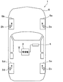
図1に示すタイヤ空気圧検出装置は、車両1に取り付けられるもので、送信機2a〜2d、受信機3および表示器4を備えて構成されている。
The tire air pressure detection device shown in FIG. 1 is attached to a vehicle 1 and includes
図1に示すように、送信機2a〜2dは、車両1における各車輪5a〜5dに取り付けられるもので、車輪5a〜5dに取り付けられたタイヤの空気圧を検出すると共に、その検出結果を示す検出信号のデータをフレーム内に格納して送信する。また、受信機3は、車両1における車体6側に取り付けられるもので、送信機2a〜2dから送信されるフレームを受信すると共に、その中に格納された検出信号に基づいて各種処理や演算等を行うことでタイヤ空気圧を検出する。
As shown in FIG. 1, the
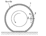
図2に示すように、送信機2a〜2dは、センシング部21、制御部(第1制御部)22、電波送信部23、電池24およびアンテナ25を備えた構成となっており、電池24からの電力供給に基づいて各部が駆動されるようになっている。送信機2a〜2dは、例えば、図4に示すように、各車輪5a〜5dに取り付けられるタイヤ7のトレッドの裏面側に取り付けられており、タイヤ7と共に回転し、タイヤ7が路面に接地したときにはその振動が印加される。
As shown in FIG. 2, the
センシング部21には、圧力センサ21aや加速度センサ21bが備えられている。そして、センシング部21は、圧力センサ21aから出力されるタイヤ空気圧に応じた検出信号と加速度センサ21bから出力されるタイヤ回転に伴って発生する加速度に応じた検出信号を制御部22に伝えている。本実施形態では、送信機2a〜2dをタイヤ7のトレッドの裏面に取り付けていることから、加速度センサ21bは、タイヤ7の回転加速度に加えて、タイヤ7が路面に接地したときに付与される加速度も検出信号として表れ、これが制御部22に伝えられている。
The
制御部22は、CPU、ROM、RAM、I/Oなどを備えた周知のマイクロコンピュータによって構成され、ROMなどにメモリに記憶されたプログラムに従って、所定の処理を実行する。制御部22内のメモリには、各送信機2a〜2dを特定するための送信機固有の識別情報と自車両を特定するための車両固有の識別情報とを含むID情報が格納されている。
The
制御部22は、圧力センサ21aから出力された検出信号を受け取り、それを信号処理すると共に必要に応じて加工し、検出結果を示すデータとして各送信機2a〜2dのID情報と共にフレーム内に格納し、そのフレームを電波送信部23に送る。具体的には、制御部22は、圧力センサ21aの検出信号に基づいてタイヤ空気圧を検出し、そのタイヤ空気圧を示すデータをID情報と共にフレーム内に格納している。
The
なお、センシング部21に温度センサを備え、温度センサで検出されたタイヤ内温度を示すデータをフレームに格納することもできる。また、検出されたタイヤ内温度に基づいて所定の基準温度でのタイヤ空気圧に換算し、その換算後のタイヤ空気圧を示すデータをフレーム内に格納するようにしても良い。さらに、制御部22自身でタイヤ空気圧低下の判定を行うようにし、タイヤ空気圧低下が生じているか否かを示すデータをフレーム内に格納して電波送信部23に送ることもできる。例えば、制御部22にて、所定の基準温度に換算したときのタイヤ空気圧を所定の警報閾値Thと比較し、タイヤ空気圧が警報閾値Th以下に低下したことを検知した場合にタイヤ空気圧低下が生じたことを示すデータをフレームに格納すれば良い。
Note that the
以下の説明では、タイヤ空気圧などの検出結果を示すデータ、および、タイヤ空気圧低下の発生の有無を示すデータのことをタイヤ空気圧に関するデータという。ただし、タイヤ空気圧に関するデータにこれらすべてのデータが必ず含まれている必要はなく、タイヤ空気圧などを示すデータと、タイヤ空気圧低下の発生の有無を示すデータの一方だけであっても良い。 In the following description, data indicating a detection result such as tire air pressure and data indicating whether or not the tire air pressure has decreased is referred to as data related to tire air pressure. However, it is not always necessary to include all these data in the tire pressure data, and only one of the data indicating the tire pressure and the data indicating whether or not the tire pressure is reduced may be included.
また、制御部22は、加速度センサ21bの検出信号に基づいて、車両の走行状態、すなわち走行中であるか停止中であるかを判定し、走行中と判定したときをフレーム送信タイミングとして、タイヤ空気圧に関するデータを格納したフレームの送信を行う。
Further, the
上記したように、送信機2a〜2dは、例えばタイヤ7のトレッドの裏面に取り付けられており、加速度センサ21bがタイヤ7の径方向(図4中の矢印A)もしくは回転方向(図4中の矢印B)の加速度を検出できるように設置されている。このため、加速度センサ21bは、タイヤ回転時にタイヤ7のトレッドのうち送信機2a〜2dが設置された位置と対応する場所(以下、設置対応場所という)が路面に接地したときに生じる振動が印加される。そして、設置対応場所が路面に接地したときには、タイヤ7が径方向に変形することからタイヤ7の径方向の加速度変化が生じる。また、設置対応場所が路面に接地したときには、タイヤ7が非接地状態から接地状態に変化して路面との間の摩擦による応力変化が生じるため、タイヤ7の回転方向の加速度も変化する。したがって、タイヤ7の径方向もしくは回転方向の加速度の変化をモニタすることで、設置対応場所が路面に接地したり、路面から離れたりすることを判別することができ、これによって車両が走行中であるか停止中であるかを判定できる。
As described above, the
例えば、タイヤ回転時における加速度センサ21bの検出信号の変化が図5のように表れ、設置対応場所が路面に接地したときに加速度が瞬間的に大きくなり、設置対応場所が路面から離れたときに加速度が瞬間的に小さくなる。このため、制御部22は、例えば、加速度が瞬間的に極大値もしくは極小値を取った場合、または、所定時間内に加速度が極大値および極小値の両方を取った場合に、車両が走行中であると判定している。そして、車両が走行中と判定すると、フレーム送信を行うようにしている。このような加速度の変化は、タイヤ回転速度にかかわらず発生することから、例えば車両が走行してから車速が30km/h以上になっていない状況であっても、フレーム送信を行うことが可能となる。したがって、より早くからタイヤ空気圧情報を通知することが可能となる。
For example, the change in the detection signal of the
電波送信部23は、アンテナ25を通じて、制御部22から送られてきたフレームをRF電波として受信機3に向けて送信する出力部としての機能を果たす。制御部22から電波送信部23へ信号を送る処理は、上記プログラムに従って所定の送信タイミング毎に実行されるように設定されている。すなわち、送信機2a〜2d側では、車両が走行中であると判定されたときを送信開始タイミングとして、タイヤ空気圧に関するデータを格納したフレーム送信を開始している。そして、車両が走行中であれば、フレーム送信を継続して行い、車両が停止するまでフレーム送信を継続する。フレーム送信の間隔については任意であるが、電池寿命を考慮して、例えばタイヤ回転数が所定回転数に達する毎にフレーム送信が行われるようにしたり、所定の定期送信周期毎にフレーム送信を行うようにすると好ましい。また、制御部22でタイヤ空気圧の低下を検出している場合には、タイヤ空気圧に応じてフレーム送信の間隔を変化させ、例えばタイヤ空気圧低下が発生したときには低下前よりも短いフレーム送信間隔でフレーム送信を行うようにすることもできる。
The radio
電池24は、センシング部21や制御部22などに対して電力供給を行っており、この電池24からの電力供給を受けて、センシング部21でのタイヤ空気圧に関するデータの収集や制御部22での各種演算などが実行される。
The
このようにして各送信機2a〜2dが構成されている。このように、送信機2a〜2dにて、該当車輪のタイヤ空気圧を検出し、各送信機2a〜2dに備えられたアンテナ25を通じて、所定の送信タイミング毎にフレームを送信するようになっている。
In this way, the
また、図3に示すように、受信機3は、アンテナ31、電波受信部32および制御部33を備えた構成となっている。
As shown in FIG. 3, the
アンテナ31は、各送信機2a〜2dから送られてくるフレームを受信するためのものである。本実施形態では、アンテナ31は、各送信機2a〜2dから送られてくるフレームを総括的に受け取る1本の共通アンテナとなっており、車体6に固定されている。
The
電波受信部32は、各送信機2a〜2dから送信されたフレームがアンテナ31で受信されると、それを入力して制御部33に送る入力部としての機能を果たすものである。
The radio
制御部(第2制御部)33は、CPU、ROM、RAM、I/Oなどを備えた周知のマイクロコンピュータによって構成され、ROMなどに記憶されたプログラムに従って、タイヤ空気圧検出に関わる各種処理を実行する。制御部33は、図示しないバッテリからの電力供給に基づいて作動し、電波受信部32でのフレーム受信や制御部33自身でのタイヤ空気圧検出に関わる各種処理などを実行する。
The control unit (second control unit) 33 is configured by a known microcomputer having a CPU, ROM, RAM, I / O, and the like, and executes various processes related to tire pressure detection according to a program stored in the ROM. To do. The
例えば、制御部33は、タイヤ空気圧検出に関わる各種処理として、電波受信部32から受け取ったフレームに格納されたタイヤ空気圧に関するデータに基づいて各種信号処理および演算等を行うことでタイヤ空気圧を求める。そして、求めたタイヤ空気圧に応じた電気信号を表示器4に出力する。例えば、制御部33は、求めたタイヤ空気圧を所定の警報閾値Thと比較し、タイヤ空気圧が所定の警報閾値Th以下に低下したことを検知した場合には、その旨の信号を表示器4に出力する。また、送信機2a〜2dでもタイヤ空気圧検出を行っている場合には、受信したフレーム中に含まれるタイヤ空気圧低下が発生したことを示すデータに基づいて、表示器4にタイヤ空気圧低下が発生したことを伝えることもできる。
For example, the
さらに、制御部33は、4つの車輪5a〜5dそれぞれのタイヤ空気圧を求め、そのタイヤ空気圧を各車輪5a〜5dと対応させて表示器4に出力することもできる。制御部33のメモリには、各車輪5a〜5dに配置されている送信機2a〜2dのID情報が各車輪5a〜5dの位置と関連づけられて記憶されている。このため、制御部33は、フレームに格納されたID情報と照合することで、受信したフレームが車輪5a〜5dのどれに取り付けられた送信機2a〜2dであるかを認識し、タイヤ空気圧が低下した車輪を特定できる。これに基づき、タイヤ空気圧低下が発生した場合に、低下した車輪を特定して表示器4に出力する。また、タイヤ空気圧低下が発生していない場合でも、求めたタイヤ空気圧を各車輪5a〜5dと対応させて、表示器4に出力するようにしても良い。
Furthermore, the
このようにして、4つの車輪5a〜5dのいずれかのタイヤ空気圧が低下したこと、もしくは、4つの車輪5a〜5dそれぞれのタイヤ空気圧が表示器4に伝えられる。
In this way, the tire air pressure of any of the four
表示器4は、図1に示されるように、ドライバが視認可能な場所に配置され、例えば車両1におけるインストルメントパネル内に設置される警報ランプやディスプレイによって構成される。この表示器4は、例えば受信機3における制御部33からタイヤ空気圧が低下した旨を示す信号が送られてくると、その旨の表示を行うことでドライバにタイヤ空気圧の低下を報知する。または、受信機3から4つの車輪5a〜5dそれぞれのタイヤ空気圧が伝えられると、各車輪5a〜5dと対応させて各タイヤ空気圧を表示する。
As shown in FIG. 1, the
以上のようにして、本実施形態にかかるタイヤ空気圧検出装置が構成されている。続いて、本実施形態のタイヤ空気圧検出装置の作動について説明する。なお、本実施形態の場合、タイヤ空気圧検出装置のうちの送信機2a〜2dで実行している処理が本発明の特徴となる部分であり、受信機3で実行している処理は従来と同様であるため、主に、送信機2a〜2dで実行している処理について説明する。
As described above, the tire pressure detection device according to the present embodiment is configured. Next, the operation of the tire pressure detection device of the present embodiment will be described. In the case of the present embodiment, the processing executed by the
まず、図6に、送信機2a〜2dの制御部22が実行するフレーム送信処理の詳細を表したフローチャートを示し、この図を参照して送信機2a〜2dの作動の一例について説明する。
First, FIG. 6 shows a flowchart showing details of the frame transmission processing executed by the
まず、初期送信フェーズとして、ステップ100、110の処理を行う。具体的には、ステップ100に示すように、所定のセンシング周期毎にセンシング部21に備えられた加速度センサ21bの検出信号に基づいて加速度検出を行い、この検出結果に基づいて1回目の路面接地を判定する。上記したように、加速度センサ21bの検出信号の変化が図5のように表れ、設置対応場所が路面に接地したときに加速度が瞬間的に大きくなり、設置対応場所が路面から離れたときに加速度が瞬間的に小さくなる。このため、制御部22は、例えば、加速度が瞬間的に極大値もしくは極小値を取った場合、または、所定時間内に加速度が極大値および極小値の両方を取った場合に、車両が走行中であると判定している。
First, steps 100 and 110 are performed as an initial transmission phase. Specifically, as shown in step 100, acceleration is detected based on the detection signal of the
そして、ステップ100で肯定判定されると、ステップ110に進み、圧力センサ21aの検出信号に基づいてタイヤ空気圧を検出する。すなわち、車両が走行中であると判定されると、圧力センサ21aにてタイヤ空気圧検出を行わせている。そして、必要に応じて温度センサで検出されるタイヤ内温度に基づいて基準温度の圧力に換算したのち、タイヤ空気圧に関するデータを自身のID情報と共にフレームに格納し、フレーム送信を行う。
If an affirmative determination is made in step 100, the process proceeds to step 110, where the tire air pressure is detected based on the detection signal of the
このように、加速度センサ21bでの検出結果に基づいて、車両が走行し始めてから1回目のフレーム送信を行うようにしている。このような加速度の変化は、タイヤ回転速度にかかわらず発生することから、例えば車両が走行してから車速が30km/h以上になっていない状況であっても、フレーム送信を行うことが可能となる。したがって、より早くからタイヤ空気圧に関するデータを送信することが可能となる。
Thus, based on the detection result of the
その後、定期送信フェーズに移り、ステップ120以降の処理を行う。まず、ステップ120では、路面接地の判定を行う。路面接地の判定は、設置対応場所が路面に接地したことの判定を行うものであり、例えば、加速度が瞬間的に極大値もしくは極小値を取った場合、または、所定時間内に加速度が極大値および極小値の両方を取った場合に、路面接地があったと判定している。そして、路面接地があったときには定期送信フェーズに移行してきてからの路面接地回数の積算値をカウントしたのち、ステップ130に進む。 Thereafter, the process proceeds to a periodic transmission phase, and the processing after step 120 is performed. First, in step 120, road surface contact is determined. The determination of road contact is to determine that the installation location is in contact with the road surface. For example, when the acceleration instantaneously takes a maximum or minimum value, or the acceleration reaches a maximum value within a predetermined time. When both the minimum value and the minimum value are taken, it is determined that there is road contact. When there is road contact, the integrated value of the number of times of road contact after shifting to the regular transmission phase is counted, and then the process proceeds to step 130.
ステップ130では、車両の停止検出を行う。具体的には、設定した期間中に、路面接地のイベントが発生していない状態であるか否かを判定する。ここでいう設定した期間とは、車両が走行中と考えられない程度に路面接地のイベントが発生しない期間に設定される。前回路面接地のイベントが発生してからの経過時間をタイマで計測し、経過時間が予め設定した時間を超える前に、次の路面接地のイベントが発生したか否かを判定することで、本処理における車両の停止検出を行っている。 In step 130, stop detection of the vehicle is performed. Specifically, it is determined whether or not a road surface grounding event has occurred during the set period. The set period here is set to a period in which a road contact event does not occur to such an extent that the vehicle is not considered to be traveling. By measuring the elapsed time since the occurrence of the previous circuit grounding event with a timer and determining whether the next road grounding event has occurred before the elapsed time exceeds the preset time, The stop of the vehicle in the process is detected.
例えば、走行していた車両が停止した場合、その後も継続的にフレーム送信を行うのは好ましくない。また、他の車両の振動がタイヤ7に伝わり、その振動が加速度として加速度センサ21bの検出信号に表れた場合などにおいても、誤ってフレーム送信が行われることがあり得る。そのようなノイズ的に車両が走行中と判定された場合に、その後もフレーム送信が継続して行われるのも好ましくない。したがって、所定期間を設定し、その設定した期間中に路面接地のイベントが発生していない状態であれば、車両が停止中であると判定して、フレーム送信処理を終了してフレーム送信を停止する。
For example, when the vehicle that was running stops, it is not preferable to continuously transmit frames after that. Further, even when the vibration of another vehicle is transmitted to the
一方、ステップ130で否定判定された場合にはステップ140に進んで停止検出に使用したタイマをクリアしたのち、ステップ150に進んで定期送信タイミングに至ったか否かの判定を行う。ここでは、タイヤ回転数が所定回転数に達する毎にフレーム送信が行われるように、路面接地回数が閾値を超えているか否かを判定している。 On the other hand, if a negative determination is made in step 130, the process proceeds to step 140 to clear the timer used for stop detection, and then the process proceeds to step 150 to determine whether or not the regular transmission timing has been reached. Here, it is determined whether or not the road surface contact count exceeds a threshold value so that frame transmission is performed every time the tire rotation speed reaches a predetermined rotation speed.
ここで肯定判定されればステップ160に進み、圧力センサ21aの検出信号に基づいてタイヤ空気圧を検出する。そして、必要に応じて温度センサで検出されるタイヤ内温度に基づいて基準温度の圧力に換算したのち、タイヤ空気圧に関するデータを自身のID情報と共にフレームに格納し、フレーム送信を行う。その後、ステップ170に進んで路面接地回数をリセットして初期化し、ステップ120以降の定期送信フェーズの各種処理を繰り返す。また、ステップ150で否定判定された場合には、まだ定期送信のタイミングに至っていないため、ステップ120以降の定期送信フェーズの各種処理を繰り返す。
If an affirmative determination is made here, the routine proceeds to step 160 where the tire pressure is detected based on the detection signal of the
このように、送信機2a〜2dに関しては、路面接地が判定されたときに、初回のフレーム送信を行い、その後は、車両の走行が継続している間はフレーム送信を継続し、車両が停止するとフレーム送信を停止するという動作が行われる。
As described above, for the
一方、受信機3については、例えばイグニッションスイッチがオンされたときに、バッテリから制御部33や電波受信部32に電力供給が行われることで作動し、フレーム受信を行う。そして、送信機2a〜2dからフレームが送信されてくると、それを受信して、タイヤ空気圧検出を行う。これに基づき、タイヤ空気圧検出の結果を表示器4に伝えることで、そのときのタイヤ空気圧を表示したり、タイヤ空気圧低下が生じていることが表示され、ドライバにタイヤ空気圧の状況が伝えられる。
On the other hand, for example, when the ignition switch is turned on, the
以上説明したように、本実施形態にかかるタイヤ空気圧検出装置では、送信機2a〜2dにおいて、加速度センサ21bの検出信号に基づいて車両の走行状態を検出し、車両が走行中と判定されたときにフレーム送信を行うようにしている。加速度の変化は、タイヤ回転速度にかかわらず発生することから、例えば車両が走行してから車速が30km/h以上になっていない状況であっても、フレーム送信を行うことが可能となる。したがって、より早くからタイヤ空気圧情報を通知することが可能となり、より早くからタイヤ空気圧低下を検知することが可能となる。
As described above, in the tire air pressure detection device according to this embodiment, when the
(他の実施形態)
本発明は上記した実施形態に限定されるものではなく、特許請求の範囲に記載した範囲内において適宜変更が可能である。
(Other embodiments)
The present invention is not limited to the embodiment described above, and can be appropriately changed within the scope described in the claims.
例えば、車両が走行中でないにもかかわらず誤ってフレーム送信が行われてしまうことを更に抑制できるように、図6のステップ120、130の処理を次のようにして行っても良い。例えば、ステップ130において設定した期間中に、路面接地のイベントが発生した回数が複数値に設定された所定の閾回数に達していれば、車両が走行中であると判定し、達していなければ車両が停止中と判定するようにしても良い。また、ステップ130において、連続する路面接地のイベントの発生タイミングの間の時間間隔が予め設定した期間以内であれば車両が走行中と判定し、その期間を超えていれば、車両が停止中と判定しても良い。 For example, it to be able further suppress the vehicle frame transmission will be performed by mistake even though the vehicle is not running, the process of step 120 in FIG. 6 may be performed as follows. For example, if the number of times that a road contact event has occurred has reached a predetermined threshold number set to a plurality of values during the period set in step 130, it is determined that the vehicle is running, and if not, It may be determined that the vehicle is stopped. Further, in step 130, if the time interval between the occurrence timings of successive road surface contact events is within a preset period, it is determined that the vehicle is traveling, and if the time interval is exceeded, the vehicle is stopped. You may judge.
また、車両が走行中でないにもかかわらず誤ってフレーム送信が行われることを抑制すべく、所定期間を設定して、その設定した期間中に路面接地のイベントが発生していなければ、フレーム送信を停止するようにしている。これは、定期送信フェーズにかかわらず、初回送信フェーズのときにも行っても良い。ただし、初回送信フェーズにおいては、より早くからタイヤ空気圧に関するデータを受信機3側に伝えたいことから、その後の定期送信フェーズにおいて、上記のような手法でフレーム送信を停止するのが好ましい。
In addition, in order to prevent erroneous frame transmission even when the vehicle is not running, a predetermined period is set. If no road contact event has occurred during the set period, frame transmission is performed. Like to stop. This may be performed during the initial transmission phase regardless of the regular transmission phase. However, in the initial transmission phase, since it is desired to transmit data related to the tire pressure to the
また、上記実施形態では、送信機2a〜2dの全体がタイヤ7のトレッドの裏面側に設置された形態について説明したが、少なくとも送信機2a〜2dのうちの加速度センサ21bがタイヤ7のトレッドの裏面側に設置されていれば良い。
Moreover, in the said embodiment, although the
1 車両
2a〜2d 送信機
3 受信機
4 表示器
5a〜5d 車輪
6 車体
7 タイヤ
21 センシング部
21a 圧力センサ
21b 加速度センサ
DESCRIPTION OF SYMBOLS 1
Claims (3)
車体側に備えられ、前記フレームを受信する電波受信部(32)と、受信した前記フレームに格納された前記タイヤ空気圧に関するデータに基づいて、タイヤ空気圧低下の発生を検出する第2制御部(33)とを有する受信機(3)とを備え、
前記第1制御部は、前記加速度センサの検出信号に基づいて、前記トレッドのうち前記加速度センサの設置場所と対応する場所である設置対応場所が路面に接地したときに発生する前記加速度の変化から車両が走行中であるか否かを判定し、前記車両が走行中であると判定したのち、前記加速度センサの検出信号が示す加速度の変化から前記設置対応場所が路面に接地したことを判定し、予め設定した期間内に前記設置対応場所が路面に接地したと判定されれば、前記設置対応場所が路面に接地した回数である路面接地回数が所定の閾値を超える毎に前記電波送信部より前記フレームの定期送信を行い、前記予め設定した期間内に前記設置対応場所が路面に接地したことが判定されなければ前記車両が停止したと判定して前記フレームの定期送信を行わないことを特徴とするタイヤ空気圧検出装置。 A pressure sensor (21a) that is provided on each of the plurality of wheels (5a to 5d) including the tire (7) and outputs a detection signal indicating the tire air pressure of each of the plurality of wheels, and a back surface of the tread of the tire A sensing unit (21) having an acceleration sensor (21b) that is attached and outputs a detection signal indicating the radial or rotational acceleration of each wheel, and processes the detection signal indicating the tire air pressure to process the tire air pressure. A transmitter (2a to 2d) having a first control unit (22) for creating a frame stored as data, and a radio wave transmission unit (23) for transmitting the frame;
Provided in the vehicle body side, the radio wave receiving unit that receives a frame (32), on the basis of data relating to the tire air pressure stored in said frame received, the second control unit that detects the occurrence of a decrease in tire air-pressure (33 And (3) a receiver having
Based on the detection signal of the acceleration sensor, the first control unit detects a change in the acceleration that occurs when an installation-corresponding location that is a location corresponding to the installation location of the acceleration sensor in the tread contacts the road surface. It is determined whether or not the vehicle is traveling, and after determining that the vehicle is traveling, it is determined from the change in acceleration indicated by the detection signal of the acceleration sensor that the installation-corresponding location is in contact with the road surface. If it is determined that the installation- corresponding location has touched the road surface within a preset period, the radio wave transmission unit receives the number of times the road surface grounding, which is the number of times the installation- corresponding location has touched the road surface, exceeds a predetermined threshold value. perform periodic transmission of the frame, wherein the installation corresponding location is determined with the vehicle if it is determined that the contact with the road surface is stopped in the frame periodically within the time preset Tire air pressure detecting device comprising means no signal.
Priority Applications (3)
| Application Number | Priority Date | Filing Date | Title |
|---|---|---|---|
| JP2014100692A JP6318835B2 (en) | 2014-05-14 | 2014-05-14 | Tire pressure detector |
| PCT/JP2015/002251 WO2015174031A1 (en) | 2014-05-14 | 2015-04-24 | Tire air pressure detection device |
| US15/308,015 US9950578B2 (en) | 2014-05-14 | 2015-04-24 | Tire air pressure detection device |
Applications Claiming Priority (1)
| Application Number | Priority Date | Filing Date | Title |
|---|---|---|---|
| JP2014100692A JP6318835B2 (en) | 2014-05-14 | 2014-05-14 | Tire pressure detector |
Publications (3)
| Publication Number | Publication Date |
|---|---|
| JP2015217712A JP2015217712A (en) | 2015-12-07 |
| JP2015217712A5 JP2015217712A5 (en) | 2016-05-26 |
| JP6318835B2 true JP6318835B2 (en) | 2018-05-09 |
Family
ID=54479583
Family Applications (1)
| Application Number | Title | Priority Date | Filing Date |
|---|---|---|---|
| JP2014100692A Active JP6318835B2 (en) | 2014-05-14 | 2014-05-14 | Tire pressure detector |
Country Status (3)
| Country | Link |
|---|---|
| US (1) | US9950578B2 (en) |
| JP (1) | JP6318835B2 (en) |
| WO (1) | WO2015174031A1 (en) |
Families Citing this family (11)
| Publication number | Priority date | Publication date | Assignee | Title |
|---|---|---|---|---|
| US9827815B2 (en) | 2013-03-15 | 2017-11-28 | Denso Corporation | Tire device |
| JP6330398B2 (en) | 2014-03-18 | 2018-05-30 | 株式会社Soken | Vehicle misstart suppression device |
| JP6318743B2 (en) | 2014-03-18 | 2018-05-09 | 株式会社Soken | Tire condition detection device |
| FR3028058B1 (en) * | 2014-10-30 | 2016-12-09 | Continental Automotive France | METHOD FOR CONTROLLING A PROCESSOR OF AN ELECTRONIC HOUSING MOUNTED ON A WHEEL OF A MOTOR VEHICLE |
| JP6128136B2 (en) * | 2015-02-06 | 2017-05-17 | トヨタ自動車株式会社 | Tire pressure sensor unit, tire pressure notification device, and vehicle |
| JP6624152B2 (en) * | 2017-04-26 | 2019-12-25 | 株式会社Soken | Tire-side device and tire device including the same |
| FR3072524B1 (en) * | 2017-10-13 | 2019-09-27 | Ldl Technology | SELF-LOCATION METHOD OF SENSORS EQUIPPING THE WHEELS OF A VEHICLE |
| JP6915507B2 (en) * | 2017-11-23 | 2021-08-04 | 株式会社デンソー | Road surface condition determination device |
| FR3077232B1 (en) * | 2018-02-01 | 2019-12-27 | Continental Automotive France | BACKUP OF THE CONTEXT OF AN ELECTRONIC MODULE OF A TIRE PRESSURE MONITORING SYSTEM FOR A MOTOR VEHICLE |
| CN116745146A (en) * | 2020-12-22 | 2023-09-12 | 米其林集团总公司 | Electronic component for transmitting identification information during a state change |
| CN115519946B (en) * | 2022-10-25 | 2023-04-25 | 深圳曦华科技有限公司 | Tire pressure signal processing method, vehicle body domain controller and related device |
Family Cites Families (8)
| Publication number | Priority date | Publication date | Assignee | Title |
|---|---|---|---|---|
| JP2005156209A (en) * | 2003-11-21 | 2005-06-16 | Toyota Motor Corp | Wheel information processor and wheel information processing method |
| GB201015520D0 (en) * | 2010-09-16 | 2010-10-27 | Schrader Electronics Ltd | Apparatus and methods for determining the position and/or orientation of a tyre mounted unit in a wheel monitoring system |
| JP2012210912A (en) * | 2011-03-31 | 2012-11-01 | Denso Corp | Wheel position detecting device and tire air pressure detecting device equipped with the same |
| US9827815B2 (en) | 2013-03-15 | 2017-11-28 | Denso Corporation | Tire device |
| JP6281346B2 (en) | 2014-03-18 | 2018-02-21 | 株式会社Soken | Road surface condition estimation device |
| JP6330398B2 (en) | 2014-03-18 | 2018-05-30 | 株式会社Soken | Vehicle misstart suppression device |
| JP6318743B2 (en) | 2014-03-18 | 2018-05-09 | 株式会社Soken | Tire condition detection device |
| JP6273937B2 (en) | 2014-03-18 | 2018-02-07 | 株式会社Soken | Road surface condition estimation device |
-
2014
- 2014-05-14 JP JP2014100692A patent/JP6318835B2/en active Active
-
2015
- 2015-04-24 US US15/308,015 patent/US9950578B2/en active Active
- 2015-04-24 WO PCT/JP2015/002251 patent/WO2015174031A1/en active Application Filing
Also Published As
| Publication number | Publication date |
|---|---|
| JP2015217712A (en) | 2015-12-07 |
| US9950578B2 (en) | 2018-04-24 |
| US20170050478A1 (en) | 2017-02-23 |
| WO2015174031A1 (en) | 2015-11-19 |
Similar Documents
| Publication | Publication Date | Title |
|---|---|---|
| JP6318835B2 (en) | Tire pressure detector | |
| JP5477368B2 (en) | Wheel position detecting device and tire air pressure detecting device having the same | |
| JP5477369B2 (en) | Wheel position detecting device and tire air pressure detecting device having the same | |
| JP5803710B2 (en) | Wheel position detecting device and tire air pressure detecting device having the same | |
| JP2005321958A (en) | Tire air pressure detection device | |
| US20160082791A1 (en) | Method and System for Tire Pressure Monitoring System (TPMS) with Time Encoded Wireless Tire Condition Sensing Device | |
| JP4924189B2 (en) | Wheel position detecting device and tire air pressure detecting device having the same | |
| WO2013187016A1 (en) | Wheel location detector device and tire air pressure detector device comprising same | |
| JP6357943B2 (en) | Tire pressure detector | |
| JP4760640B2 (en) | Wheel position detecting device and tire air pressure detecting device having the same | |
| JP2015217712A5 (en) | ||
| JP5803555B2 (en) | Wheel position detecting device and tire air pressure detecting device having the same | |
| JP2013014223A (en) | Sensor unit registration system | |
| JP2013001219A (en) | Wheel position detection device, and tire pneumatic pressure detection device having the same | |
| JP5954006B2 (en) | Wheel position detecting device and tire air pressure detecting device having the same | |
| JP5018220B2 (en) | Wheel position detecting device and tire air pressure detecting device having the same | |
| US20170305212A1 (en) | Method and System for Tire Pressure Monitoring System (TPMS) with Time Encoded Wireless Tire Condition Sensing Device and Synchronization | |
| JP2008062701A (en) | Device and method for detecting wheel position, and tire pressure detection device provided with device for detecting wheel position | |
| JP5772285B2 (en) | Self-vehicle signal discriminating device and tire air pressure detecting device having the same | |
| JP2013222428A (en) | Tire air pressure detection device | |
| JP6375970B2 (en) | Wheel position detection device and tire air pressure detection system including the same | |
| WO2016121365A1 (en) | Wheel position detection device and tire pressure detection system provided with same | |
| JP5626126B2 (en) | Wheel position detecting device and tire air pressure detecting device having the same | |
| JP2017128164A (en) | Tire air pressure monitoring system | |
| JP2016037233A (en) | Tire inflation pressure detection device |
Legal Events
| Date | Code | Title | Description |
|---|---|---|---|
| A521 | Request for written amendment filed |
Free format text: JAPANESE INTERMEDIATE CODE: A523 Effective date: 20160401 |
|
| A621 | Written request for application examination |
Free format text: JAPANESE INTERMEDIATE CODE: A621 Effective date: 20170217 |
|
| A131 | Notification of reasons for refusal |
Free format text: JAPANESE INTERMEDIATE CODE: A131 Effective date: 20171205 |
|
| A521 | Request for written amendment filed |
Free format text: JAPANESE INTERMEDIATE CODE: A523 Effective date: 20180202 |
|
| TRDD | Decision of grant or rejection written | ||
| A01 | Written decision to grant a patent or to grant a registration (utility model) |
Free format text: JAPANESE INTERMEDIATE CODE: A01 Effective date: 20180306 |
|
| A61 | First payment of annual fees (during grant procedure) |
Free format text: JAPANESE INTERMEDIATE CODE: A61 Effective date: 20180319 |
|
| R151 | Written notification of patent or utility model registration |
Ref document number: 6318835 Country of ref document: JP Free format text: JAPANESE INTERMEDIATE CODE: R151 |
|
| R250 | Receipt of annual fees |
Free format text: JAPANESE INTERMEDIATE CODE: R250 |
|
| R250 | Receipt of annual fees |
Free format text: JAPANESE INTERMEDIATE CODE: R250 |
|
| R250 | Receipt of annual fees |
Free format text: JAPANESE INTERMEDIATE CODE: R250 |
|
| R250 | Receipt of annual fees |
Free format text: JAPANESE INTERMEDIATE CODE: R250 |