JP6915507B2 - Road surface condition determination device - Google Patents
Road surface condition determination device Download PDFInfo
- Publication number
- JP6915507B2 JP6915507B2 JP2017225269A JP2017225269A JP6915507B2 JP 6915507 B2 JP6915507 B2 JP 6915507B2 JP 2017225269 A JP2017225269 A JP 2017225269A JP 2017225269 A JP2017225269 A JP 2017225269A JP 6915507 B2 JP6915507 B2 JP 6915507B2
- Authority
- JP
- Japan
- Prior art keywords
- road surface
- tire
- data
- side device
- surface data
- Prior art date
- Legal status (The legal status is an assumption and is not a legal conclusion. Google has not performed a legal analysis and makes no representation as to the accuracy of the status listed.)
- Active
Links
Images


Classifications
-
- G—PHYSICS
- G01—MEASURING; TESTING
- G01B—MEASURING LENGTH, THICKNESS OR SIMILAR LINEAR DIMENSIONS; MEASURING ANGLES; MEASURING AREAS; MEASURING IRREGULARITIES OF SURFACES OR CONTOURS
- G01B17/00—Measuring arrangements characterised by the use of infrasonic, sonic or ultrasonic vibrations
-
- B—PERFORMING OPERATIONS; TRANSPORTING
- B60—VEHICLES IN GENERAL
- B60C—VEHICLE TYRES; TYRE INFLATION; TYRE CHANGING; CONNECTING VALVES TO INFLATABLE ELASTIC BODIES IN GENERAL; DEVICES OR ARRANGEMENTS RELATED TO TYRES
- B60C23/00—Devices for measuring, signalling, controlling, or distributing tyre pressure or temperature, specially adapted for mounting on vehicles; Arrangement of tyre inflating devices on vehicles, e.g. of pumps or of tanks; Tyre cooling arrangements
- B60C23/02—Signalling devices actuated by tyre pressure
- B60C23/04—Signalling devices actuated by tyre pressure mounted on the wheel or tyre
- B60C23/0486—Signalling devices actuated by tyre pressure mounted on the wheel or tyre comprising additional sensors in the wheel or tyre mounted monitoring device, e.g. movement sensors, microphones or earth magnetic field sensors
-
- B—PERFORMING OPERATIONS; TRANSPORTING
- B60—VEHICLES IN GENERAL
- B60T—VEHICLE BRAKE CONTROL SYSTEMS OR PARTS THEREOF; BRAKE CONTROL SYSTEMS OR PARTS THEREOF, IN GENERAL; ARRANGEMENT OF BRAKING ELEMENTS ON VEHICLES IN GENERAL; PORTABLE DEVICES FOR PREVENTING UNWANTED MOVEMENT OF VEHICLES; VEHICLE MODIFICATIONS TO FACILITATE COOLING OF BRAKES
- B60T8/00—Arrangements for adjusting wheel-braking force to meet varying vehicular or ground-surface conditions, e.g. limiting or varying distribution of braking force
- B60T8/17—Using electrical or electronic regulation means to control braking
- B60T8/172—Determining control parameters used in the regulation, e.g. by calculations involving measured or detected parameters
-
- B—PERFORMING OPERATIONS; TRANSPORTING
- B60—VEHICLES IN GENERAL
- B60W—CONJOINT CONTROL OF VEHICLE SUB-UNITS OF DIFFERENT TYPE OR DIFFERENT FUNCTION; CONTROL SYSTEMS SPECIALLY ADAPTED FOR HYBRID VEHICLES; ROAD VEHICLE DRIVE CONTROL SYSTEMS FOR PURPOSES NOT RELATED TO THE CONTROL OF A PARTICULAR SUB-UNIT
- B60W10/00—Conjoint control of vehicle sub-units of different type or different function
- B60W10/18—Conjoint control of vehicle sub-units of different type or different function including control of braking systems
- B60W10/184—Conjoint control of vehicle sub-units of different type or different function including control of braking systems with wheel brakes
-
- B—PERFORMING OPERATIONS; TRANSPORTING
- B60—VEHICLES IN GENERAL
- B60W—CONJOINT CONTROL OF VEHICLE SUB-UNITS OF DIFFERENT TYPE OR DIFFERENT FUNCTION; CONTROL SYSTEMS SPECIALLY ADAPTED FOR HYBRID VEHICLES; ROAD VEHICLE DRIVE CONTROL SYSTEMS FOR PURPOSES NOT RELATED TO THE CONTROL OF A PARTICULAR SUB-UNIT
- B60W40/00—Estimation or calculation of non-directly measurable driving parameters for road vehicle drive control systems not related to the control of a particular sub unit, e.g. by using mathematical models
- B60W40/02—Estimation or calculation of non-directly measurable driving parameters for road vehicle drive control systems not related to the control of a particular sub unit, e.g. by using mathematical models related to ambient conditions
- B60W40/06—Road conditions
-
- B—PERFORMING OPERATIONS; TRANSPORTING
- B60—VEHICLES IN GENERAL
- B60W—CONJOINT CONTROL OF VEHICLE SUB-UNITS OF DIFFERENT TYPE OR DIFFERENT FUNCTION; CONTROL SYSTEMS SPECIALLY ADAPTED FOR HYBRID VEHICLES; ROAD VEHICLE DRIVE CONTROL SYSTEMS FOR PURPOSES NOT RELATED TO THE CONTROL OF A PARTICULAR SUB-UNIT
- B60W50/00—Details of control systems for road vehicle drive control not related to the control of a particular sub-unit, e.g. process diagnostic or vehicle driver interfaces
- B60W50/08—Interaction between the driver and the control system
- B60W50/14—Means for informing the driver, warning the driver or prompting a driver intervention
-
- G—PHYSICS
- G01—MEASURING; TESTING
- G01P—MEASURING LINEAR OR ANGULAR SPEED, ACCELERATION, DECELERATION, OR SHOCK; INDICATING PRESENCE, ABSENCE, OR DIRECTION, OF MOVEMENT
- G01P15/00—Measuring acceleration; Measuring deceleration; Measuring shock, i.e. sudden change of acceleration
-
- H—ELECTRICITY
- H04—ELECTRIC COMMUNICATION TECHNIQUE
- H04W—WIRELESS COMMUNICATION NETWORKS
- H04W4/00—Services specially adapted for wireless communication networks; Facilities therefor
- H04W4/30—Services specially adapted for particular environments, situations or purposes
- H04W4/40—Services specially adapted for particular environments, situations or purposes for vehicles, e.g. vehicle-to-pedestrians [V2P]
-
- B—PERFORMING OPERATIONS; TRANSPORTING
- B60—VEHICLES IN GENERAL
- B60T—VEHICLE BRAKE CONTROL SYSTEMS OR PARTS THEREOF; BRAKE CONTROL SYSTEMS OR PARTS THEREOF, IN GENERAL; ARRANGEMENT OF BRAKING ELEMENTS ON VEHICLES IN GENERAL; PORTABLE DEVICES FOR PREVENTING UNWANTED MOVEMENT OF VEHICLES; VEHICLE MODIFICATIONS TO FACILITATE COOLING OF BRAKES
- B60T2210/00—Detection or estimation of road or environment conditions; Detection or estimation of road shapes
- B60T2210/10—Detection or estimation of road conditions
- B60T2210/12—Friction
-
- B—PERFORMING OPERATIONS; TRANSPORTING
- B60—VEHICLES IN GENERAL
- B60W—CONJOINT CONTROL OF VEHICLE SUB-UNITS OF DIFFERENT TYPE OR DIFFERENT FUNCTION; CONTROL SYSTEMS SPECIALLY ADAPTED FOR HYBRID VEHICLES; ROAD VEHICLE DRIVE CONTROL SYSTEMS FOR PURPOSES NOT RELATED TO THE CONTROL OF A PARTICULAR SUB-UNIT
- B60W50/00—Details of control systems for road vehicle drive control not related to the control of a particular sub-unit, e.g. process diagnostic or vehicle driver interfaces
- B60W2050/0001—Details of the control system
- B60W2050/0043—Signal treatments, identification of variables or parameters, parameter estimation or state estimation
- B60W2050/0057—Frequency analysis, spectral techniques or transforms
-
- B—PERFORMING OPERATIONS; TRANSPORTING
- B60—VEHICLES IN GENERAL
- B60W—CONJOINT CONTROL OF VEHICLE SUB-UNITS OF DIFFERENT TYPE OR DIFFERENT FUNCTION; CONTROL SYSTEMS SPECIALLY ADAPTED FOR HYBRID VEHICLES; ROAD VEHICLE DRIVE CONTROL SYSTEMS FOR PURPOSES NOT RELATED TO THE CONTROL OF A PARTICULAR SUB-UNIT
- B60W50/00—Details of control systems for road vehicle drive control not related to the control of a particular sub-unit, e.g. process diagnostic or vehicle driver interfaces
- B60W2050/0062—Adapting control system settings
- B60W2050/0075—Automatic parameter input, automatic initialising or calibrating means
- B60W2050/009—Priority selection
- B60W2050/0091—Priority selection of control inputs
-
- B—PERFORMING OPERATIONS; TRANSPORTING
- B60—VEHICLES IN GENERAL
- B60W—CONJOINT CONTROL OF VEHICLE SUB-UNITS OF DIFFERENT TYPE OR DIFFERENT FUNCTION; CONTROL SYSTEMS SPECIALLY ADAPTED FOR HYBRID VEHICLES; ROAD VEHICLE DRIVE CONTROL SYSTEMS FOR PURPOSES NOT RELATED TO THE CONTROL OF A PARTICULAR SUB-UNIT
- B60W50/00—Details of control systems for road vehicle drive control not related to the control of a particular sub-unit, e.g. process diagnostic or vehicle driver interfaces
- B60W50/08—Interaction between the driver and the control system
- B60W50/14—Means for informing the driver, warning the driver or prompting a driver intervention
- B60W2050/143—Alarm means
-
- B—PERFORMING OPERATIONS; TRANSPORTING
- B60—VEHICLES IN GENERAL
- B60W—CONJOINT CONTROL OF VEHICLE SUB-UNITS OF DIFFERENT TYPE OR DIFFERENT FUNCTION; CONTROL SYSTEMS SPECIALLY ADAPTED FOR HYBRID VEHICLES; ROAD VEHICLE DRIVE CONTROL SYSTEMS FOR PURPOSES NOT RELATED TO THE CONTROL OF A PARTICULAR SUB-UNIT
- B60W2422/00—Indexing codes relating to the special location or mounting of sensors
- B60W2422/70—Indexing codes relating to the special location or mounting of sensors on the wheel or the tire
-
- B—PERFORMING OPERATIONS; TRANSPORTING
- B60—VEHICLES IN GENERAL
- B60W—CONJOINT CONTROL OF VEHICLE SUB-UNITS OF DIFFERENT TYPE OR DIFFERENT FUNCTION; CONTROL SYSTEMS SPECIALLY ADAPTED FOR HYBRID VEHICLES; ROAD VEHICLE DRIVE CONTROL SYSTEMS FOR PURPOSES NOT RELATED TO THE CONTROL OF A PARTICULAR SUB-UNIT
- B60W2422/00—Indexing codes relating to the special location or mounting of sensors
- B60W2422/95—Measuring the same parameter at multiple locations of the vehicle
-
- H—ELECTRICITY
- H04—ELECTRIC COMMUNICATION TECHNIQUE
- H04W—WIRELESS COMMUNICATION NETWORKS
- H04W4/00—Services specially adapted for wireless communication networks; Facilities therefor
- H04W4/02—Services making use of location information
- H04W4/025—Services making use of location information using location based information parameters
- H04W4/027—Services making use of location information using location based information parameters using movement velocity, acceleration information
-
- H—ELECTRICITY
- H04—ELECTRIC COMMUNICATION TECHNIQUE
- H04W—WIRELESS COMMUNICATION NETWORKS
- H04W4/00—Services specially adapted for wireless communication networks; Facilities therefor
- H04W4/30—Services specially adapted for particular environments, situations or purposes
- H04W4/38—Services specially adapted for particular environments, situations or purposes for collecting sensor information
-
- H—ELECTRICITY
- H04—ELECTRIC COMMUNICATION TECHNIQUE
- H04W—WIRELESS COMMUNICATION NETWORKS
- H04W4/00—Services specially adapted for wireless communication networks; Facilities therefor
- H04W4/80—Services using short range communication, e.g. near-field communication [NFC], radio-frequency identification [RFID] or low energy communication
Description
本発明は、タイヤ側装置にてタイヤが受ける振動を検出すると共に、振動データに基づいて路面状態を示す路面データを作成して車体側システムに伝え、その路面データに基づいて路面状態を判別する路面状態判別装置に関する。 In the present invention, the tire-side device detects the vibration received by the tire, creates road surface data indicating the road surface condition based on the vibration data, transmits the road surface data to the vehicle body side system, and determines the road surface condition based on the road surface data. The present invention relates to a road surface condition discriminating device.
従来、特許文献1において、タイヤトレッドの裏面に加速度センサを備え、加速度センサにてタイヤに加えられる振動を検出すると共に、その振動の検出結果に基づいて路面状態の判別を行う路面状態判別方法が提案されている。この路面状態判別方法では、加速度センサが検出したタイヤの振動波形から特徴ベクトルを抽出し、抽出した特徴ベクトルと路面の種類ごとに記憶しておいた全サポートベクタとの類似度を計算することで、路面状態を判別する。例えば、カーネル関数を用いて、抽出した特徴ベクトルと全サポートベクタとの類似度が計算され、最も類似度が高い路面の種類、例えばドライ路面、ウェット路面、凍結路、積雪路などが現在走行中の路面状態であると判別される。このような路面状態判別方法により、ロバスト性の高い路面判定を行うことが可能となる。
Conventionally, in
しかしながら、各タイヤに備えられた加速度センサなどのタイヤ側装置から振動の検出結果などのデータを車体側に備えられる車体側システムの受信機に伝える際に、一部のタイヤについてデータが受信機で受信できない可能性がある。例えば、受信機の接地場所が一部のタイヤから離れている場合や、タイヤの回転に伴って加速度センサがNullの位置にある場合など、タイヤ側装置からの電波が受信機で受信されないことがあり得る。 However, when data such as vibration detection results are transmitted from the tire side device such as the acceleration sensor provided on each tire to the receiver of the vehicle body side system provided on the vehicle body side, the data for some tires is transmitted by the receiver. It may not be possible to receive. For example, when the ground contact location of the receiver is far from some tires, or when the accelerometer is in the Null position as the tires rotate, the radio waves from the tire side device may not be received by the receiver. possible.
本発明は上記点に鑑みて、各タイヤに備えられるタイヤ側装置から車体側システムに確実にデータを伝えることができる路面状態判別装置を提供することを目的とする。 In view of the above points, it is an object of the present invention to provide a road surface condition discriminating device capable of reliably transmitting data from a tire-side device provided on each tire to a vehicle body-side system.
上記目的を達成するため、請求項1に記載の路面状態判別装置は、車両に備えられる複数のタイヤ(3)それぞれに取り付けられ、タイヤの振動の大きさに応じた検出信号を出力する振動検出部(10)と、検出信号の波形に現れる路面状態を示す路面データを生成する波形処理部(11)と、路面データを送信する第1データ通信部(12)と、を有するタイヤ側装置(1)と、第1データ通信部から送信された路面データを受信する第2データ通信部(24)と、路面データに基づいて車両の走行路面の路面状態を判別する路面判別部(25)と、を備えている。そして、複数のタイヤそれぞれに取り付けられた複数のタイヤ側装置は、該複数のタイヤ側装置同士の間において路面データの受信を行い、かつ、該複数のタイヤ側装置のうち他のタイヤ側装置よりも車体側システムとの間の電波環境が良い少なくとも1つのタイヤ側装置は、通信により受信した他のタイヤ側装置の路面データを含めた路面データを車体側システムに送信する。また、第1データ通信部と第2データ通信部との間は双方向通信が行われ、路面判別部は、複数のタイヤ側装置から送信された路面データを受信したときの受信強度を測定し、他のタイヤ側装置よりも受信強度が高いものを少なくとも1つのタイヤ側装置として、該少なくとも1つのタイヤ側装置をセントラル装置に設定すると共に他のタイヤ側装置をペリフェラル装置に設定し、第2データ通信部より複数のタイヤ側装置それぞれがセントラル装置であるかペリフェラル装置であるかを示すデータを送信する。
In order to achieve the above object, the road surface condition determination device according to
このように、複数のタイヤ側装置のうち他のタイヤ側装置よりも車体側システムとの間の電波環境が良い少なくとも1つのタイヤ側装置から、それよりも電波環境が良くない他のタイヤ側装置の路面データも含めて車体側システムに伝えるようにしている。このようにすることで、他のタイヤ側装置から路面データを送ったとしたら車体側システムに届かない可能性があるような状況においても、確実に車体側システムに伝えることができる。よって、各タイヤに備えられるタイヤ側装置から車体側システムに確実にデータを伝えることができる路面状態判別装置とすることが可能となる。 In this way, from at least one tire-side device having a better radio wave environment with the vehicle body-side system than the other tire-side devices among the plurality of tire-side devices, another tire-side device having a worse radio wave environment than that. The road surface data is also included in the vehicle body side system. By doing so, even in a situation where the road surface data may not reach the vehicle body side system if the road surface data is sent from another tire side device, it can be reliably transmitted to the vehicle body side system. Therefore, it is possible to provide a road surface condition discriminating device capable of reliably transmitting data from the tire-side device provided on each tire to the vehicle body-side system.
請求項3に記載の路面状態判別装置では、複数のタイヤそれぞれに取り付けられた複数のタイヤ側装置は、それぞれ、該複数のタイヤ側装置同士の間において路面データの受信を行い、かつ、通信により受信した他のタイヤ側装置の路面データを含めた路面データを車体側システムに送信する。
In the road surface condition determination device according to
このように、複数のタイヤ側装置から、通信により受信した他のタイヤ側装置の路面データを含めた路面データを車体側システムに送信させている。このようにしても、各タイヤに備えられるタイヤ側装置から車体側システムに確実に路面データを伝えることができる路面状態判別装置とすることが可能となる。 In this way, the road surface data including the road surface data of the other tire side devices received by communication is transmitted from the plurality of tire side devices to the vehicle body side system. Even in this way, it is possible to provide a road surface condition discriminating device capable of reliably transmitting road surface data from the tire side device provided on each tire to the vehicle body side system.
請求項4に記載の路面状態判別装置では、複数のタイヤそれぞれに取り付けられた複数のタイヤ側装置は、それぞれ、該複数のタイヤ側装置同士の間において路面データの受信を行え、車体側システムは、複数のタイヤ側装置から送信された路面データのうちの一部を受信していないと、複数のタイヤ側装置のうち路面データが受信できたものに対してデータ要求を行って路面データを受信していないタイヤ側装置の該路面データを送信させる。 In the road surface condition determination device according to claim 4 , the plurality of tire-side devices attached to each of the plurality of tires can receive road surface data between the plurality of tire-side devices, respectively, and the vehicle body-side system can receive the road surface data. If a part of the road surface data transmitted from a plurality of tire-side devices is not received, a data request is made to a plurality of tire-side devices for which the road surface data can be received and the road surface data is received. The road surface data of the tire-side device that has not been used is transmitted.
このように、各タイヤ側装置から路面データを送信させたのち、車体側システムで受信できなかった路面データがあった場合に、受信できたタイヤ側装置に対してデータ要求を行うようにしている。このようにしても、各タイヤに備えられるタイヤ側装置から車体側システムに確実に路面データを伝えることができる路面状態判別装置とすることが可能となる。 In this way, after the road surface data is transmitted from each tire side device, if there is road surface data that could not be received by the vehicle body side system, the data request is made to the tire side device that could be received. .. Even in this way, it is possible to provide a road surface condition discriminating device capable of reliably transmitting road surface data from the tire side device provided on each tire to the vehicle body side system.
なお、上記各手段の括弧内の符号は、後述する実施形態に記載の具体的手段との対応関係の一例を示すものである。 The reference numerals in parentheses of each of the above means indicate an example of the correspondence with the specific means described in the embodiment described later.
以下、本発明の実施形態について図に基づいて説明する。なお、以下の各実施形態相互において、互いに同一もしくは均等である部分には、同一符号を付して説明を行う。 Hereinafter, embodiments of the present invention will be described with reference to the drawings. In each of the following embodiments, parts that are the same or equal to each other will be described with the same reference numerals.
(第1実施形態)
図1〜図8を参照して、本実施形態にかかる路面状態判別機能を有するタイヤ装置100について説明する。本実施形態にかかるタイヤ装置100は、車両の各車輪に備えられるタイヤの接地面に加わる振動に基づいて走行中の路面状態を判別すると共に、路面状態に基づいて車両の危険性の報知や車両運動制御などを行うものである。
(First Embodiment)
The
図1および図2に示すようにタイヤ装置100は、車輪側に設けられたタイヤ側装置1と、車体側に備えられた各部を含む車体側システム2とを有する構成とされている。車体側システム2としては、受信機21、ブレーキ制御用の電子制御装置(以下、ブレーキECUという)22、報知装置23などが備えられている。なお、このタイヤ装置100のうち路面状態判別機能を実現する部分が路面状態判別装置に相当する。本実施形態の場合、タイヤ側装置1と車体側システム2のうちの受信機21が路面状態判別装置を構成している。
As shown in FIGS. 1 and 2, the
本実施形態のタイヤ装置100は、タイヤ側装置1よりタイヤ3が走行中の路面状態に応じたデータ(以下、路面データという)を送信すると共に、受信機21で路面データを受信して路面状態の判別を行う。また、タイヤ装置100は、受信機21での路面状態の判別結果を報知装置23に伝え、報知装置23より路面状態の判別結果を報知させる。これにより、例えばドライ路やウェット路もしくは凍結路であることなど、路面状態をドライバに伝えることが可能となり、滑り易い路面である場合にはドライバに警告することも可能となる。また、タイヤ装置100は、車両運動制御を行うブレーキECU22などに路面状態を伝えることで、危険を回避するための車両運動制御が行われるようにする。例えば、凍結時には、ドライ路の場合と比較してブレーキ操作量に対して発生させられる制動力が弱められるようにすることで、路面μが低いときに対応じた車両運動制御となるようにする。具体的には、タイヤ側装置1および受信機21は、以下のように構成されている。
The
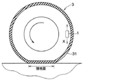
タイヤ側装置1は、各タイヤ3それぞれに配置され、車体側システム2との間において双方向通信が可能とされていると共に、各タイヤ側装置1同士の間においても双方向通信が可能とされている。具体的には、タイヤ側装置1は、図2に示すように、振動センサ部10、波形処理部11、データ通信部12および電源部13を備えた構成とされ、例えば、図3に示されるように、タイヤ3のトレッド31の裏面側に設けられる。
The tire-
振動センサ部10は、タイヤ3に加わる振動を検出するための振動検出部を構成するものである。例えば、振動センサ部10は、加速度センサによって構成される。振動センサ部10が加速度センサとされる場合、振動センサ部10は、タイヤ3が回転する際にタイヤ側装置1が描く円軌道に対して接する方向、つまり図3中の矢印Xで示すタイヤ接線方向の振動の大きさに応じた検出信号として、加速度の検出信号を出力する。より詳しくは、振動センサ部10は、矢印Xで示す二方向のうちの一方向を正、反対方向を負とする出力電圧などを検出信号として発生させる。例えば、振動センサ部10は、タイヤ3が1回転するよりも短い周期に設定される所定のサンプリング周期ごとに加速度検出を行い、それを検出信号として出力している。なお、振動センサ部10の検出信号は、出力電圧もしくは出力電流として表されるが、ここでは出力電圧として表される場合を例に挙げる。
The
波形処理部11は、CPU、ROM、RAM、I/Oなどを備えた周知のマイクロコンピュータによって構成され、ROMなどに記憶されたプログラムに従って検出信号の信号処理を行い、検出信号に現れる路面状態を示す路面データを生成する。
The
具体的には、波形処理部11は、振動センサ部10が出力する検出信号をタイヤ接線方向の振動データを表す検出信号として用いて、この検出信号が示す振動波形の波形処理を行うことで、タイヤ振動の特徴量を抽出する。本実施形態の場合、タイヤ3の加速度(以下、タイヤGという)の検出信号を信号処理することで、タイヤGの特徴量を抽出する。また、波形処理部11は、抽出した特徴量を含むデータを路面データとしてデータ通信部12に伝える。なお、ここでいう特徴量の詳細については後で説明する。
Specifically, the
また、波形処理部11は、データ通信部12からのデータ送信を制御しており、データ送信を行わせたいタイミングでデータ通信部12に対して路面データを伝えることで、データ通信部12からデータ通信が行われるようにする。例えば、波形処理部11は、タイヤ3が1回転するごとにタイヤGの特徴量の抽出を行い、タイヤ3が1回転もしくは複数回転する毎に1回もしくは複数回の割合で、データ通信部12に対して路面データを伝えている。例えば、波形処理部11は、データ通信部12に対して路面データを伝えるときのタイヤ3の1回転中に抽出されたタイヤGの特徴量を含んだ路面データをデータ通信部12に対して伝えている。
Further, the
データ通信部12は、車体側システム2との間において双方向通信を行ったり、他のタイヤ側装置1との間において通信を行う第1データ通信部に相当する部分である。双方向通信の形態については様々なものを適用することができ、BLE(Bluetooth Low Energyの略)通信を含むブルートゥース通信、wifiなどの無線LAN(Local Area Networkの略)、Sub-GHz通信、ウルトラワイドバンド通信、ZigBeeなどを適用できる。なお、「ブルートゥース」は登録商標である。
The
データ通信部12は、例えば、波形処理部11から路面データが伝えられると、そのタイミングで路面データの送信を行う。データ通信部12からのデータ送信のタイミングについては、波形処理部11によって制御され、波形処理部11からタイヤ3が1回転もしくは複数回転するごとに路面データが送られてくるたびに、データ通信部12からのデータ送信が行われるようになっている。
For example, when the road surface data is transmitted from the
また、データ通信部12は、セントラル装置であるかペリフェラル装置であるかを示す指示信号を受信し、指示信号の内容を波形処理部11に伝える役割を果たす。
Further, the
ここでいう指示信号は、車体側システム2から送られてくる信号であり、各タイヤ側装置1に対して、自身がセントラル装置であるか、それともペリフェラル装置であるかを示す信号である。セントラル装置は、ペリフェラル装置との間においてデータの送受信を行えるものである。セントラル装置は、自身のデータに加えてペリフェラル装置から伝えられたデータについても車体側システム2に送信することができる。ペリフェラル装置は、セントラル装置との間においてデータ送信を行うものであり、ここではセントラル装置からのデータを受信する動作は行わないが、受信できるようにされていても良い。
The instruction signal referred to here is a signal sent from the vehicle
指示信号は、各タイヤ側装置1に対して個別に伝えられるものであっても良いし、すべてのタイヤ側装置1についてのセントラル装置とペリフェラル装置のいずれであるかを示したものであっても良い。各タイヤ側装置1には、固有識別情報(以下、ID情報という)が割り当てられている。指示信号が各タイヤ側装置1に個別に伝えられるものとされる場合、その指示信号に該当するタイヤ側装置1のID情報が付されることで、各タイヤ側装置1は、指示信号が自身に対する信号であるか否かを識別できるようにしている。また、指示信号がすべてのタイヤ側装置1についてのセントラル装置とペリフェラル装置のいずれであるかを示したものとされる場合、ID情報とセントラル装置であるかペリフェラル装置であるかを示すデータを関連付けるようにしている。このように、ID情報ごとにセントラル装置であるかペリフェラル装置であるかが指示信号に基づいて把握できる。このため、各タイヤ側装置1は、自身がセントラル装置であるかペリフェラル装置であるか識別できるだけでなく、他のタイヤ側装置1がセントラル装置であるかペリフェラル装置であるかも識別できる。
The instruction signal may be transmitted individually to each tire-
なお、各タイヤ側装置1では、装置製造時に、波形処理部11を構成するマイクロコンピュータのROMなどのメモリに、自身がセントラル装置とペリフェラル装置のいずれであるかを記憶しておくこともできる。ただし、ID情報以外についてはメモリの記憶内容を同じにすることが好ましい。このため、ここでは装置製造時に、波形処理部11のメモリに自身がセントラル装置とペリフェラル装置のいずれであるかを記憶していない場合について説明する。また、各タイヤ側装置1は、車体側システム2からのデータを受信すると、そのデータの内容を記憶しておき、自身がセントラル装置とペリフェラル装置のいずれであるかを認識できるようにするが、タイヤ3が回転を停止してから所定時間経過するとそれを消去する。これにより、タイヤ3がローテーションなどされた場合に、各タイヤ側装置1をセントラル装置とペリフェラル装置のいずれにするかを改めて設定できるようにしている。
At the time of manufacturing the device, each tire-
電源部13は、タイヤ側装置1の電源となるものであり、タイヤ側装置1に備えられる各部への電力供給を行うことで、各部が作動させられるようにしている。電源部13は、例えばボタン電池等の電池で構成される。タイヤ側装置1がタイヤ3内に備えられることから、容易に電池交換を行うことができないため、消費電力の軽減を図ることが必要となっている。
The
一方、車体側システム2を構成する受信機21やブレーキECU22および報知装置23は、図示しないイグニッションスイッチなどの起動スイッチがオンされると駆動されるものである。
On the other hand, the
受信機21は、図2に示すように、データ通信部24と路面判別部25とを有した構成とされている。
As shown in FIG. 2, the
データ通信部24は、タイヤ側装置1との間において双方向通信を行う第2データ通信部に相当する部分である。データ通信部24は、タイヤ側装置1のデータ通信部12より送信された特徴量を含む路面データを受信し、路面判別部25に伝える役割を果たす。
The
路面判別部25は、CPU、ROM、RAM、I/Oなどを備えた周知のマイクロコンピュータによって構成され、ROMなどに記憶されたプログラムに従って各種処理を行っている。本実施形態の場合、路面判別部25は、データ通信部24で路面データを受信したときの受信強度の測定を行っている。
The road
また、路面判別部25は、受信した路面データに基づいて路面状態の判定を行う。具体的には、路面判別部25は、サポートベクタを保存しており、波形処理部11から伝えられる路面データとサポートベクタとを比較することで路面状態の判別を行っている。
Further, the road
サポートベクタは、路面の種類ごとに記憶され、保存されている。サポートベクタは、手本となる特徴量のことであり、例えばサポートベクタマシンを用いた学習によって得ている。タイヤ側装置1を備えた車両を実験的に路面の種類別に走行させ、そのときに波形処理部11で抽出した特徴量を所定のタイヤ回転数分学習し、その中から典型的な特徴量を所定数分抽出したものがサポートベクタとされる。例えば、路面の種類別に、100万回転分の特徴量を学習し、その中から100回転分の典型的な特徴量を抽出したものをサポートベクタとしている。
Support vectors are stored and stored for each type of road surface. The support vector is a feature quantity that serves as a model, and is obtained by learning using, for example, a support vector machine. A vehicle equipped with the tire-
そして、路面判別部25は、データ通信部24が受信したタイヤ側装置1より送られてきた特徴量と、保存された路面の種類別のサポートベクタとを比較することで、路面状態を判別する。例えば、今回受信した路面データに含まれる特徴量を路面の種類別のサポートベクタと対比して、その特徴量が最も近いサポートベクタの路面を現在の走行路面と判別している。
Then, the road
また、路面判別部25は、路面状態を判別すると、判別した路面状態を報知装置23に伝え、必要に応じて報知装置23より路面状態をドライバに伝える。これにより、ドライバは路面状態に対応した運転を心掛けるようになり、車両の危険性を回避することが可能となる。例えば、報知装置23を通じて判別された路面状態を常に表示するようにしても良いし、判別された路面状態がウェット路や凍結路等のように運転をより慎重に行う必要があるときにのみ路面状態を表示してドライバに警告するようにしても良い。また、受信機21からブレーキECU22などの車両運動制御を実行するためのECUに対して路面状態を伝えており、伝えられた路面状態に基づいて車両運動制御が実行されるようにしている。
Further, when the road
なお、ブレーキECU22は、様々なブレーキ制御を行う制動制御装置を構成するものである。具体的には、ブレーキECU22は、ブレーキ液圧制御用のアクチュエータを駆動することでホイールシリンダ圧を増減して制動力を制御する。また、ブレーキECU22は、各車輪の制動力を独立して制御することもできる。このブレーキECU22により、受信機21から路面状態が伝えられると、それに基づいて車両運動制御として制動力の制御を行っている。例えば、ブレーキECU22は、伝えられた路面状態が凍結路であることを示していた場合、ドライ路面と比較して、ドライバによるブレーキ操作量に対して発生させる制動力を弱めるようにする。これにより、車輪スリップを抑制でき、車両の危険性を回避することが可能となる。
The
また、報知装置23は、例えばメータ表示器などで構成され、ドライバに対して路面状態を報知する際に用いられる。報知装置23をメータ表示器で構成する場合、ドライバが車両の運転中に視認可能な場所に配置され、例えば車両におけるインストルメントパネル内に設置される。メータ表示器は、受信機21から路面状態が伝えられると、その路面状態が把握できる態様で表示を行うことで、視覚的にドライバに対して路面状態を報知することができる。
Further, the
なお、報知装置23をブザーや音声案内装置などで構成することもできる。その場合、報知装置23は、ブザー音や音声案内によって、聴覚的にドライバに対して路面状態を報知することができる。また、視覚的な報知を行う報知装置23としてメータ表示器を例に挙げたが、ヘッドアップディスプレイなどの情報表示を行う表示器によって報知装置23を構成しても良い。
The
このようにして、本実施形態にかかるタイヤ装置100が構成されている。なお、車体側システム2を構成する各部は、例えばCAN(Controller Area Networkの略)通信などによる車内LAN(Local Area Networkの略)を通じて接続されている。このため、車内LANを通じて各部が互いに情報伝達できるようになっている。
In this way, the
以上のようにして、本実施形態にかかるタイヤ装置100が構成されている。次に、上記した波形処理部11で抽出する特徴量の詳細について説明する。
As described above, the
ここでいう特徴量とは、振動センサ部10が取得したタイヤ3に加わる振動の特徴を示す量であり、例えば特徴ベクトルとして表される。
The feature amount referred to here is a quantity indicating the feature of the vibration applied to the
タイヤ回転時における振動センサ部10の検出信号の出力電圧波形は、例えば図4に示す波形となる。この図に示されるように、タイヤ3の回転に伴ってトレッド31のうち振動センサ部10の配置箇所と対応する部分が接地し始めた接地開始時に、振動センサ部10の出力電圧が極大値をとる。以下、この振動センサ部10の出力電圧が極大値をとる接地開始時のピーク値を第1ピーク値という。さらに、図4に示されるように、タイヤ3の回転に伴ってトレッド31のうち振動センサ部10の配置箇所と対応する部分が接地していた状態から接地しなくなる接地終了時に、振動センサ部10の出力電圧が極小値をとる。以下、この振動センサ部10の出力電圧が極小値をとる接地終了時のピーク値を第2ピーク値という。
The output voltage waveform of the detection signal of the
振動センサ部10の出力電圧が上記のようなタイミングでピーク値をとるのは、以下の理由による。すなわち、タイヤ3の回転に伴ってトレッド31のうち振動センサ部10の配置箇所と対応する部分が接地する際、振動センサ部10の近傍においてタイヤ3のうちそれまで略円筒面であった部分が押圧されて平面状に変形する。このときの衝撃を受けることで、振動センサ部10の出力電圧が第1ピーク値をとる。また、タイヤ3の回転に伴ってトレッド31のうち振動センサ部10の配置箇所と対応する部分が接地面から離れる際には、振動センサ部10の近傍においてタイヤ3は押圧が解放されて平面状から略円筒状に戻る。このタイヤ3の形状が元に戻るときの衝撃を受けることで、振動センサ部10の出力電圧が第2ピーク値をとる。このようにして、振動センサ部10の出力電圧が接地開始時と接地終了時でそれぞれ第1、第2ピーク値をとるのである。また、タイヤ3が押圧される際の衝撃の方向と、押圧から開放される際の衝撃の方向は逆方向であるため、出力電圧の符号も逆方向となる。
The output voltage of the
ここで、タイヤトレッド31のうち振動センサ部10の配置箇所と対応する部分が路面に接地した瞬間を「踏み込み領域」、路面から離れる瞬間を「蹴り出し領域」とする。「踏み込み領域」には、第1ピーク値となるタイミングが含まれ、「蹴り出し領域」には、第2ピーク値となるタイミングが含まれる。また、踏み込み領域の前を「踏み込み前領域」、踏み込み領域から蹴り出し領域までの領域、つまりタイヤトレッド31のうち振動センサ部10の配置箇所と対応する部分が接地中の領域を「蹴り出し前領域」、蹴り出し領域後を「蹴り出し後領域」とする。このように、タイヤトレッド31のうち振動センサ部10の配置箇所と対応する部分が接地する期間およびその前後を5つの領域に区画することができる。なお、図4中では、検出信号のうちの「踏み込み前領域」、「踏み込み領域」、「蹴り出し前領域」、「蹴り出し領域」、「蹴り出し後領域」を順に5つの領域R1〜R5として示してある。
Here, the moment when the portion of the
路面状態に応じて、区画した各領域でタイヤ3に生じる振動が変動し、振動センサ部10の検出信号が変化することから、各領域での振動センサ部10の検出信号を周波数解析することで、車両の走行路面における路面状態を検出する。例えば、圧雪路のような滑り易い路面状態では蹴り出し時の剪断力が低下するため、蹴り出し領域R4や蹴り出し後領域R5において、1kHz〜4kHz帯域から選択される帯域値が小さくなる。このように、路面状態に応じて振動センサ部10の検出信号の各周波数成分が変化することから、検出信号の周波数解析に基づいて路面状態を判定することが可能になる。
Since the vibration generated in the
このため、波形処理部11は、連続した時間軸波形となっているタイヤ3の1回転分の振動センサ部10の検出信号を、図5に示すように所定の時間幅Tの時間窓毎に複数の区画に分割し、各区画で周波数解析を行うことで特徴量を抽出している。具体的には、各区画で周波数解析を行うことで、各周波数帯域でのパワースペクトル値、つまり特定周波数帯域の振動レベルを求め、このパワースペクトル値を特徴量としている。
Therefore, the
なお、時間幅Tの時間窓で分割された区画の数は車速に応じて、より詳しくはタイヤ3の回転速度に応じて変動する値である。以下の説明では、タイヤ1回転分の区画数をn(ただし、nは自然数)としている。
The number of sections divided by the time window of the time width T is a value that fluctuates according to the vehicle speed, and more specifically, according to the rotation speed of the
例えば、各区画それぞれの検出信号を複数の特定周波数帯域のフィルタ、例えば0〜1kHz、1〜2kHz、2〜3kHz、3〜4kHz、4〜5kHzの5つのバンドパスフィルタに通して得られたパワースペクトル値を特徴量としている。この特徴量は、特徴ベクトルと呼ばれるもので、ある区画i(ただし、iは1≦i≦nの自然数)の特徴ベクトルXiは、各特定周波数帯域のパワースペクトル値をaikで示すと、これを要素とする行列として、次式のように表される。 For example, the power obtained by passing the detection signal of each partition through a plurality of specific frequency band filters, for example, five bandpass filters of 0 to 1 kHz, 1 to 2 kHz, 2 to 3 kHz, 3 to 4 kHz, and 4 to 5 kHz. The spectral value is used as a feature quantity. This feature amount is called a feature vector, and the feature vector Xi of a certain section i (where i is a natural number of 1 ≦ i ≦ n) is expressed by a ik indicating the power spectrum value of each specific frequency band. As a matrix whose elements are, it is expressed as follows.

続いて、本実施形態にかかるタイヤ装置100による路面状態判別について、図6〜図7を参照して説明する。なお、ここでは、車両が停止している状態から走行を開始した状態を想定して説明を行う。
Subsequently, the road surface condition determination by the
各車輪のタイヤ側装置1では、波形処理部11にて、図6に示すデータ送信処理を実行している。一方、車体側システム2では、路面判別部25において、図7に示す路面状態判別理が実行される。なお、以下では、図6および図7の各処理を走行開始時から時系列に沿って順番に説明していく。
In the tire-
まず、各タイヤ側装置1では、波形処理部11は、所定の制御周期毎に図6に示すデータ送信処理を実行する。ステップS100では、振動センサ部10の検出信号の入力処理を行う。この処理は、続くステップS110において、タイヤ3が1回転するまでの期間継続される。そして、振動センサ部10の検出信号をタイヤ1回転分入力すると、その後のステップS120に進み、入力したタイヤ1回転分の振動センサ部10の検出信号の時間軸波形の特徴量を抽出する。
First, in each tire-
なお、タイヤ3が1回転したことについては、振動センサ部10の検出信号の時間軸波形に基づいて判定している。すなわち、検出信号は図4に示した時間軸波形を描くことから、検出信号の第1ピーク値や第2ピーク値を確認することでタイヤ3の1回転を把握することができる。
It should be noted that the fact that the
また、路面状態が検出信号の時間軸波形の変化として特に現れるのが、「踏み込み領域」、「蹴り出し前領域」、「蹴り出し領域」を含めたその前後の期間である。このため、この期間中のデータが入力されていれば良く、必ずしもタイヤ1回転中における振動センサ部10の検出信号すべてのデータを入力していなくても良い。例えば、「踏み込み前領域」や「蹴り出し後領域」については、「踏み込み領域」の近傍や「蹴り出し領域」の近傍のデータがあれば良い。このため、振動センサ部10の検出信号のうちの振動レベルが所定の閾値よりも小さくなる領域については、「踏み込み前領域」や「蹴り出し後領域」の中でも路面状態の影響を受け難い期間として、検出信号の入力を行わないようにしても良い。
Further, the road surface condition particularly appears as a change in the time-axis waveform of the detection signal in the period before and after the "stepping area", "pre-kicking area", and "kicking area". Therefore, it is sufficient that the data during this period is input, and it is not always necessary to input all the data of the detection signals of the
また、ステップS120で行う特徴量の抽出については、上述した通りの手法によって行っている。 Further, the feature amount extraction performed in step S120 is performed by the method as described above.
その後、ステップS130において、波形処理部11は、自身のタイヤ側装置1がセントラル装置であるか否かを判定する。走行開始時には、セントラル装置とペリフェラル装置のいずれであるかの記憶内容が消去されているため、本ステップでは否定判定され、ステップS140に進むことになる。
After that, in step S130, the
そして、ステップS140に進み、データ送信を実行すべく、今回の制御周期の際に抽出した特徴量を含む路面データをデータ通信部12に伝える。これにより、データ通信部12より、特徴量を含む路面データが送信される。
Then, in order to proceed to step S140 and execute data transmission, the road surface data including the feature amount extracted during this control cycle is transmitted to the
一方、受信機21では、イグニッションスイッチなどの起動スイッチがオンされると、路面判別部25が図7に示す路面状態判別処理を実行する。この処理は、所定の制御周期ごとに実行される。
On the other hand, in the
まず、ステップS200では、データ受信処理が行われる。この処理は、データ通信部24が路面データを受信したときに、その路面データを路面判別部25が取り込むことによって行われる。データ通信部24がデータ受信を行っていないときには、路面判別部
25は何も路面データを取り込むことなく本処理を終えることになる。
First, in step S200, data reception processing is performed. This processing is performed by the road
この後、ステップS210に進み、データ受信が有ったか否かを判定する。ここで、受信していた場合にはステップS220に進み、受信していなければ受信するまでステップS200、S210の処理が繰り返される。 After that, the process proceeds to step S210 to determine whether or not data has been received. Here, if it has been received, the process proceeds to step S220, and if it has not been received, the processes of steps S200 and S210 are repeated until it is received.
ステップS220では、セントラル装置が設定済みであるか否かが判定される。走行開始時には、セントラル装置の設定はまだされていないため、ここでは否定判定され、ステップS230に進むことになる。 In step S220, it is determined whether or not the central device has been set. At the start of traveling, the central device has not been set yet, so a negative determination is made here, and the process proceeds to step S230.
ステップS230では、受信強度、つまりデータを受信したときの電波強度を測定する。各タイヤ側装置1からデータ送信を行った場合、電波強度は、タイヤ側装置1から受信機21までの距離や周辺環境、例えばどの経路を通じてタイヤ側装置1から受信機21まで電波が伝わるか等に応じて減衰する。そして、各タイヤ側装置1からデータ送信が行われる際に用いられる電波の強度は決まっていることから、受信強度が大きいほど電波環境が良く、受信機21まで電波が伝わりやすいことを意味している。したがって、ステップS240に進んだのち、ステップS230で測定した受信強度に基づき、例えば各タイヤ側装置1のうち電波の受信強度が最も高かったものをセントラル装置と設定する。また、タイヤ側装置1のうちセントラル装置として設定されたもの以外についてはペリフェラル装置と設定する。
In step S230, the reception intensity, that is, the radio wave intensity when the data is received is measured. When data is transmitted from each tire-
そして、ステップS250に進み、各タイヤ側装置1がセントラル装置とペリフェラル装置のいずれであるかのデータを示した指示信号を各タイヤ側装置1のID情報と対応付けて、各タイヤ側装置1に送信する。これにより、各タイヤ側装置1は、自身がセントラル装置とペリフェラル装置のいずれであるかを認識することが可能となる。
Then, the process proceeds to step S250, and the instruction signal indicating whether each tire-
なお、ここでは車体側システム2との間の電波環境が良いセントラル装置として、受信強度が最も大きなタイヤ側装置1を選択するようにしている。しかしながら、これは一例であり、複数のタイヤ側装置1のうち他のタイヤ側装置1よりも受信強度が高い少なくとも1つをセントラル装置として設定すればよい。また、タイヤ3の回転に伴って電波環境も変化する可能性があることから、受信強度を複数回測定した結果に基づき、例えば平均値が最も高いタイヤ側装置1などをセントラル装置に設定するようにしても良い。
Here, the tire-
その後、ステップ260に進み、路面状態の判別を行う。路面状態の判別については、受信した路面データに含まれる特徴量と、路面判別部25に保存された路面の種類別のサポートベクタとを比較することで、路面状態を判別する。例えば、特徴量を路面の種類別の全サポートベクタとの類似度を求め、最も類似度が高かったサポートベクタの路面を現在の走行路面と判別している。
After that, the process proceeds to step 260 to determine the road surface condition. Regarding the determination of the road surface condition, the road surface condition is determined by comparing the feature amount included in the received road surface data with the support vector for each type of the road surface stored in the road
例えば、特徴量を路面の種類別の全サポートベクタとの類似度の算出は、次のような手法によって行うことができる。 For example, the degree of similarity between the feature quantity and all the support vectors for each type of road surface can be calculated by the following method.
上記したように特徴量を表す行列式Xについて、特徴量の行列式をX(r)、サポートベクタの行列式をX(s)とし、それぞれの行列式の各要素となるパワースペクトル値aikをa(r)ik,a(s)ikで表すとする。その場合、特徴量の行列式X(r)とサポートベクタの行列式X(s)は、それぞれ次のように表される。 Regarding the determinant X representing the feature quantity as described above, the determinant of the feature quantity is X (r), the determinant of the support vector is X (s), and the power spectrum value a ik which is each element of each determinant. Is represented by a (r) ik and a (s) ik. In that case, the determinant X (r) of the feature quantity and the determinant X (s) of the support vector are expressed as follows.
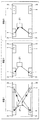
例えば、図8に示すように、振動センサ部10の検出信号の時間軸波形について、今回のタイヤ3の回転時の時間軸波形とサポートベクタの時間軸波形それぞれを所定の時間幅Tの時間窓で各区画に分割する。図示例の場合、各時間軸波形を5つの区画に分割しているため、n=5となり、iは、1≦i≦5で表される。ここで、図中に示したように、今回のタイヤ3の回転時の各区画の特徴ベクトルXiをXi(r)、サポートベクタの各区画の特徴ベクトルをXi(s)とする。その場合、各区画の特徴ベクトルXiが示す座標間の距離Kyzについては、今回のタイヤ3の回転時の各区画の特徴ベクトルXi(r)を含む横の升とサポートベクタの各区画の特徴ベクトルXi(s)を含む縦の升とが交差する升のように示される。なお、距離Kyzについて、yはXi(s)におけるiを書き換えたものであり、zはXi(r)におけるiを書き換えたものである。なお、実際には、車速に応じて、今回のタイヤ3の回転時とサポートベクタとの区画数は異なったものとなり得るが、ここでは等しくなる場合を例に挙げてある。
For example, as shown in FIG. 8, regarding the time axis waveform of the detection signal of the
本実施形態の場合、5つの特定周波数帯域に分けて特徴ベクトルを取得している。このため、時間軸と合わせた6次元空間において各区画の特徴ベクトルXiが表されることとなり、区画同士の特徴ベクトルがXi示す座標間の距離は、6次元空間における座標間の距離となる。ただし、各区画の特徴ベクトルが示す座標間の距離については、特徴量とサポートベクタとが似ているほど小さく、似ていないほど大きくなることから、当該距離が小さいほど類似度が高く、距離が大きいほど類似度が低いことを示している。 In the case of this embodiment, the feature vector is acquired by dividing into five specific frequency bands. Therefore, the feature vector Xi of each section is represented in the 6-dimensional space aligned with the time axis, and the distance between the coordinates indicated by the feature vector Xi between the sections is the distance between the coordinates in the 6-dimensional space. However, the distance between the coordinates indicated by the feature vector of each section is smaller as the feature amount and the support vector are similar, and larger as they are not similar. Therefore, the smaller the distance, the higher the similarity and the greater the distance. The larger the value, the lower the similarity.
例えば、時分割によって区画1〜nとされている場合、区画1同士の特徴ベクトルが示す座標間の距離Kyzについては、次式で示される。
For example, when the
なお、ここでは類似度に対応する値として各区画の特徴ベクトルが示す2つの座標間の距離Kyzの総和Ktotalを用いているが、類似度を示すパラメータとして他のものを用いることもできる。例えば、類似度を示すパラメータとして、総和Ktotalを区画数で割って求めた距離Kyzの平均値である平均距離Kaveを用いたり、特許文献1に示されているように、様々なカーネル関数を用いて類似度を求めることもできるし、類似度の低いパスを除いて類似度の演算を行うようにしても良い。
Here, the sum K total of the distance Kyz between the two coordinates indicated by the feature vector of each section is used as the value corresponding to the similarity, but other parameters may be used as the parameter indicating the similarity. .. For example, as a parameter indicating the degree of similarity , the average distance Kave , which is the average value of the distance Kyz obtained by dividing the total K total by the number of sections, is used, or as shown in
一方、上記したように、ステップS250においてセントラル装置とペリフェラル装置のいずれであるかのデータが示された指示信号が送信されると、各タイヤ側装置1では、自身がセントラル装置とペリフェラル装置のいずれであるかを認識できるようになる。したがって、この後は、セントラル装置に設定されたタイヤ側装置1では、ステップS130で肯定判定されてステップS150に進む。
On the other hand, as described above, when the instruction signal indicating which of the central device and the peripheral device is transmitted is transmitted in step S250, each
そして、ステップS150において、波形処理部11はデータ受信処理を行う。これにより、セントラル装置に設定されたタイヤ側装置1は、ペリフェラル装置に設定された他のタイヤ側装置1からの路面データを受信する。なお、ここではステップS150の処理として記載してあるが、データ受信については必ずしも図6に示した処理の順番に行われる必要はなく、データ送信処理が実行されている期間中のどのタイミングで実行されても構わない。
Then, in step S150, the
続いて、ステップS160でペリフェラル装置に設定された全タイヤ側装置1からの路面データを受信したと判定されると、ステップS170に進み、セントラル装置に設定されたタイヤ側装置1より路面データの送信が行われる。このとき、セントラル装置に設定されたタイヤ側装置1の波形処理部11は、自身の特徴量に加えて、ペリフェラル装置に設定されたタイヤ側装置1が送ってきた路面データに含まれる特徴量も含めて、路面データとして送信する。また、路面データには、各特徴量がどのタイヤ側装置1で抽出されたものであるかが把握できるように、各タイヤ側装置1のID情報との対応付けを行っている。
Subsequently, when it is determined in step S160 that the road surface data from all the tire-
なお、ペリフェラル装置に設定された各タイヤ側装置1では、ステップS130で否定判定されることになるため、ステップS140において特徴量を含む路面データの送信が行われる。セントラル装置に設定されたタイヤ側装置1は、このペリフェラル装置に設定された各タイヤ側装置1から送信された路面データをステップS150の処理で受信している。
In each tire-
また、セントラル装置が設定されてからは、図7に示す路面状態判別処理におけるステップS220で肯定判定されて、ステップS230〜S250の処理を省略してステップS260の処理が実行される。そして、図6のステップS170でセントラル装置に設定されたタイヤ側装置1から送信された路面データ、つまりセントラル装置とペリフェラル装置の双方のタイヤ側装置1で抽出された特徴量に基づいて、路面状態の判別が行われる。
After the central device is set, an affirmative determination is made in step S220 in the road surface condition determination process shown in FIG. 7, and the process of steps S230 to S250 is omitted and the process of step S260 is executed. Then, based on the road surface data transmitted from the tire-
このように、電波環境が良好なセントラル装置に設定されたタイヤ側装置1からそれよりも電波環境が良くないペリフェラル装置に設定されたタイヤ側装置1の路面データも含めて車体側システム2に伝えるようにしている。
In this way, the road surface data of the
すなわち、セントラル装置およびペリフェラル装置の設定が完了すると、まずは図9の状態1に示すようにセントラル装置に設定されたタイヤ側装置1に向けてペリフェラル装置に設定された各タイヤ側装置1から路面データが伝えられる。そして、図9の状態2に示すようにセントラル装置に設定されたタイヤ側装置1からペリフェラル装置に設定された各タイヤ側装置1で抽出された特徴量を含めた路面データが車体側システム2に伝えられる。
That is, when the settings of the central device and the peripheral device are completed, first, as shown in the
このようにすることで、ペリフェラル装置に設定されたタイヤ側装置1から路面データを送ったとしたら車体側システム2に届かない可能性があるような状況においても、確実に車体側システム2に伝えることができる。よって、各タイヤに備えられるタイヤ側装置から車体側システムに確実にデータを伝えることができる路面状態判別装置とすることが可能となる。
By doing so, even in a situation where the road surface data may not reach the vehicle
なお、図9中の細線矢印は、タイヤ側装置1から自身の特徴量を含めた路面データが送信されていることを意味している。また、太線矢印は、タイヤ側装置1から自身の特徴量に加えて他のタイヤ側装置1の特徴量を含めた路面データが送信されていることを示している。この後の説明において用いている図面についても、細線矢印と太線矢印の意味は上記と同様である。
The thin arrow in FIG. 9 means that the road surface data including its own feature amount is transmitted from the
また、ここでは4輪車両を例に挙げて説明したが、本実施形態の路面状態判別装置については、トラック、トレーラーのように4輪よりも多い複数の車輪が備えられる大型車両などについても適用できる。 Further, although the four-wheel vehicle has been described as an example here, the road surface condition determination device of the present embodiment is also applied to a large vehicle having a plurality of wheels more than four wheels such as a truck and a trailer. can.
例えば、図10の紙面左側を車両前方として、図中状態1に示すように、車両における右側の前方から第2輪目がセントラル装置に設定されるような電波環境であるとする。このような場合にも、状態1に示すようにセントラル装置が設定されると、セントラル装置に設定されたタイヤ側装置1に向けてペリフェラル装置に設定された各タイヤ側装置1から路面データが伝えられる。そして、図中状態2に示すようにセントラル装置に設定されたタイヤ側装置1からペリフェラル装置に設定された各タイヤ側装置1で抽出された特徴量を含めた路面データが受信機21に伝えられる。このように、4輪よりも多くの車輪を有する車両の路面状態判別装置にも適用可能である。特に、大型車両については、受信機21からの距離が離れる車輪については電波環境が悪くなり易く、受信機21を複数カ所に設置することが必要になる場合もあり得る。そのような場合には、本実施形態のようにして路面状態の判別が行えるようにすると、受信機21を1つで済ませることが可能となり、装置構成を簡略化できるという効果も得られる。
For example, it is assumed that the left side of the paper in FIG. 10 is the front of the vehicle, and as shown in the
なお、ステップS210では、基本的には、受信機21がすべてのタイヤ側装置1の路面データを受信したときに肯定判定されるようにするが、すべてのタイヤ側装置1の路面データを受信できない可能性もある。このため、例えば受信機21に自車両のタイヤ側装置1のID情報を予め登録しておくことで、一部のタイヤ側装置1からの路面データが受信できなかったとしても、受信できていないタイヤ側装置1がペリフェラル装置であることを特定することができる。
In step S210, basically, when the
また、車体側システム2からセントラル装置とペリフェラル装置のいずれであるかを示すデータが届く前のときには、図6のステップS130で肯定判定されるようにしておくこともできる。この場合、各タイヤ側装置1で、自身の路面データを送信させてからステップS150のデータ受信処理を行わせ、その後ステップS160の処理を行わせることで、自身以外のタイヤ側装置1の特徴量を含めた路面データを送信させる。このようにすれば、受信機21では、各タイヤ側装置1のうち路面データを受信できたものの受信強度の大きさに基づいてセントラル装置を設定することができる。また、受信機21では、受信できた路面データに含まれた各タイヤ側装置1のID情報から、路面データが受信できていないタイヤ側装置1を特定し、そのタイヤ側装置1をペリフェラル装置に設定することができる。したがって、事前に各タイヤ側装置1のID情報を登録しておかなくても、すべてのタイヤ側装置1について洩れなくセントラル装置かペリフェラル装置のいずれかに設定することができる。
Further, before the data indicating which of the central device and the peripheral device is received from the vehicle
(第2実施形態)
第2実施形態について説明する。本実施形態は、第1実施形態に対して路面状態の判別手法を変更するものであり、その他については第1実施形態と同様であるため、第1実施形態と異なる部分についてのみ説明する。
(Second Embodiment)
The second embodiment will be described. This embodiment is different from the first embodiment in the method of determining the road surface condition, and the other parts are the same as those of the first embodiment. Therefore, only the parts different from the first embodiment will be described.
本実施形態では、セントラル装置およびペリフェラル装置の設定を行うのではなく、各タイヤ側装置1が他のタイヤ側装置1が送信した路面データを受信し、その路面データに含まれる特徴量と自身が抽出した特徴量とを含めた路面データを再度送信するようにする。
In the present embodiment, instead of setting the central device and the peripheral device, each tire-
具体的には、本実施形態の各タイヤ側装置1の波形処理部11では図11に示すデータ送信処理を実行し、受信機21の路面判別部25では図12に示す路面状態判別処理を実行する。
Specifically, the
まず、図11のデータ送信処理では、ステップS300〜S320において、図6のステップS100〜S120と同様の処理を行い、ステップS330において、ステップS140と同様に各タイヤ側装置1から自身で抽出した特徴量を含む路面データの送信を行う。そして、各タイヤ側装置1は、ステップS340、S350において、ステップS150、S160と同様に、データ受信処理を行うと共に、路面データとして、自身で抽出した特徴量に加えて他のタイヤ側装置1が送ってきた路面データに含まれる特徴量を含めたものを送信する。また、路面データには、各特徴量がどのタイヤ側装置1で抽出されたものであるかが把握できるように、各タイヤ側装置1のID情報も含める。
First, in the data transmission process of FIG. 11, in steps S300 to S320, the same processing as in steps S100 to S120 of FIG. 6 is performed, and in step S330, the feature extracted from each
一方、図12の路面状態判別処理では、ステップS400〜S420において、図7のステップS200、S210、S260と同様の処理を行うことで、路面状態を判別する。なお、ステップS410では、図11のステップS350で送信された他のタイヤ側装置1の特徴量を含む路面データを受信した場合に肯定判定されるようにしている。しかしながら、ステップS330で送信された路面データをすべてのタイヤ側装置1について受信している場合でも、肯定判定されるようにしても良い。
On the other hand, in the road surface condition determination process of FIG. 12, the road surface condition is determined by performing the same processing as in steps S200, S210, and S260 of FIG. 7 in steps S400 to S420. In step S410, when the road surface data including the feature amount of the other
このような処理が行われる場合、まずは図13の状態1に示すようにすべてのタイヤ側装置1から路面データが車体側システム2に向けて送信される。そして、その後に、状態2に示すように再びすべてのタイヤ側装置1から他のタイヤ側装置1で抽出された特徴量も含めた路面データが送信される。
When such processing is performed, first, as shown in the
このように、各タイヤ側装置1から路面データを送信させたのち、各タイヤ側装置1で他の路面データを受信し、今度は各タイヤ側装置1から他のタイヤ側装置1で抽出された特徴量を含む路面データを送信させるようにしている。このようにしても、第1実施形態と同様に、各タイヤに備えられるタイヤ側装置1から車体側システム2に確実に路面データを伝えることができる路面状態判別装置とすることが可能となる。
In this way, after transmitting the road surface data from each
なお、本実施形態の場合、各タイヤ側装置1から受信機21への通信が行えれば良く、受信機21から各タイヤ側装置1への通信を行う必要はないため、各タイヤ側装置1と受信機21については必ずしも双方向通信が行える形態でなくても良い。また、本実施形態のような路面状態装置も、4輪車両に限らず、4輪よりも多い複数の車輪が適用される大型車両などに適用することができる。この場合も、第1実施形態と同様の効果を得ることができる。
In the case of the present embodiment, it is sufficient that the communication from each
(第3実施形態)
第3実施形態について説明する。本実施形態も、第1実施形態に対して路面状態の判別手法を変更するものであり、その他については第1実施形態と同様であるため、第1実施形態と異なる部分についてのみ説明する。
(Third Embodiment)
The third embodiment will be described. This embodiment also changes the road surface condition determination method with respect to the first embodiment, and is the same as the first embodiment in other respects. Therefore, only the parts different from the first embodiment will be described.
本実施形態では、各タイヤ側装置1から路面データを送信させるようにしつつ、複数のタイヤ側装置1のうち受信機21で受信できなかったものがある場合に、受信できたタイヤ側装置1に対して路面データを送信させるデータ要求信号を出すようにする。
In the present embodiment, when road surface data is transmitted from each tire-
具体的には、本実施形態の各タイヤ側装置1の波形処理部11では図14に示すデータ送信処理を実行し、受信機21の路面判別部25では図15に示す路面状態判別処理を実行する。
Specifically, the
まず、図14のデータ送信処理では、ステップS500〜S520において、図6のステップS100〜S120と同様の処理を行い、ステップS530において、ステップS140と同様に各タイヤ側装置1から自身で抽出した特徴量を含む路面データの送信を行う。そして、各タイヤ側装置1は、ステップS540において、ステップS150と同様に、データ受信処理を行うことで他のタイヤ側装置1からの路面データを受信する。その後、ステップS550に進み、データ要求があるか否かを判定する。
First, in the data transmission process of FIG. 14, in steps S500 to S520, the same processing as in steps S100 to S120 of FIG. 6 is performed, and in step S530, the feature extracted from each
ここでいうデータ要求とは、後述するように受信機21から出される路面データの送信要求であり、受信機21が路面データを受信できなかったタイヤ側装置1があった場合に、受信できたタイヤ側装置1に対して出される要求である。
The data request referred to here is a request for transmitting road surface data issued from the
ここで肯定判定された場合にはステップS560に進み、路面データとして、自身で抽出した特徴量に加えて他のタイヤ側装置1が送ってきた路面データに含まれる特徴量を含めたものを送信する。また、路面データには、各特徴量がどのタイヤ側装置1で抽出されたものであるかが把握できるように、各タイヤ側装置1のID情報も含める。なお、ここでは路面データにすべてのタイヤ側装置1で抽出された特徴量を含めるようにしている。しかしながら、受信機21から受信できなかったタイヤ側装置1を特定してデータ要求を出すようにし、少なくとも受信できなかったタイヤ側装置1で抽出された特徴量を含めるようにしていれば良い。
If an affirmative judgment is made here, the process proceeds to step S560, and the road surface data including the feature amount included in the road surface data sent by the other
一方、図15の路面状態判別処理では、ステップS600〜S620において、図7のステップS200、S210、S260と同様の処理を行うことで、路面状態を判別する。また、ステップS610で否定判定された場合には、ステップS600に戻るのではなくステップS630に進み、受信できたタイヤ側装置1に対してデータ要求信号を出力する。例えば、データ要求信号に、受信できたタイヤ側装置1のID情報を含めることで、各タイヤ側装置1で自身にデータ要求がなされているか否かを認識することが可能となる。また、このときに、上記したように受信できなかったタイヤ側装置1を特定してデータ要求を出すようにすることもできる。
On the other hand, in the road surface condition determination process of FIG. 15, in steps S600 to S620, the road surface condition is determined by performing the same processing as in steps S200, S210, and S260 of FIG. If a negative determination is made in step S610, the process proceeds to step S630 instead of returning to step S600, and a data request signal is output to the tire-
このようにして、受信機21で受信が行われたタイヤ側装置1に対してデータ要求信号が出されると、その後は、図14のステップS560において、路面データとして、自身で抽出した特徴量に加えて他のタイヤ側装置1が送ってきた路面データに含まれる特徴量を含めたものを送信される。この路面データに基づいて、受信機21では、路面状態を判別することができる。
In this way, when the data request signal is output to the tire-
このような処理が行われる場合、まずは図16の状態1に示すようにすべてのタイヤ側装置1から路面データが車体側システム2に向けて送信される。そして、図中“X”で示したように、複数のタイヤ側装置1のうち受信機21で路面データを受信できなかったものがあった場合、状態2の破線矢印で示すように、路面データを受信できたタイヤ側装置1に対してデータ要求信号が出される。その後、状態3に示すように、データ要求信号を受けたタイヤ側装置1から、再び自身および他のタイヤ側装置1で抽出された特徴量を含めた路面データが送信される。
When such processing is performed, first, as shown in the
このように、各タイヤ側装置1から路面データを送信させたのち、受信機21で受信できなかった路面データがあった場合に、受信できたタイヤ側装置1に対してデータ要求信号を出すようにしている。このようにしても、各タイヤに備えられるタイヤ側装置1から車体側システム2に確実に路面データを伝えることができる路面状態判別装置とすることが可能となる。
In this way, after the road surface data is transmitted from each
なお、本実施形態のような路面状態装置も、4輪車両に限らず、4輪よりも多い複数の車輪が適用される大型車両などに適用することができる。この場合も、第1実施形態と同様の効果を得ることができる。 The road surface condition device as in this embodiment can be applied not only to a four-wheeled vehicle but also to a large vehicle to which a plurality of wheels having more than four wheels are applied. In this case as well, the same effect as that of the first embodiment can be obtained.
例えば、大型車両などでは、図17の状態1に示すように、受信機21に近いタイヤ側装置1については受信機21で路面データを受信できるが、受信機21から遠いタイヤ側装置1については受信機21には路面データが届かない。しかしながら、受信機21から遠いタイヤ側装置1が送信した路面データは、受信機21に近いタイヤ側装置1には届く。
For example, in a large vehicle or the like, as shown in the
このため、まずは受信機21から近いタイヤ側装置1が送信した路面データを受信し、受信機21から遠いタイヤ側装置1については、受信機21から近いタイヤ側装置1を介してデータ要求が出される。そして、図17の状態2に示すように、受信機21から遠いタイヤ側装置1が受信機21から近いタイヤ側装置1より受信機21に伝えられる。このようにして、各タイヤ3に備えられたタイヤ側装置1からの路面データに基づいて、路面状態の判別を行うことができる。
Therefore, first, the road surface data transmitted by the tire-
(他の実施形態)
本発明は上記した実施形態に限定されるものではなく、特許請求の範囲に記載した範囲内において適宜変更が可能である。
(Other embodiments)
The present invention is not limited to the above-described embodiment, and can be appropriately modified within the scope of the claims.
(1)例えば、上記実施形態では、振動センサ部10を加速度センサによって構成する場合を例示したが、他の振動検出を行うことができる素子、例えば圧電素子などによって振動センサ部10を構成することもできる。
(1) For example, in the above embodiment, the case where the
(2)また、上記実施形態では、振動センサ部10の検出信号に現れる路面状態を示す路面データとして、特徴量を含むデータを用いている。しかしながら、これも一例を示したに過ぎず、他のデータを路面データとして用いても良い。例えば、タイヤ3の1回転中の振動データに含まれる5つの領域R1〜R5それぞれの振動波形の積分値データを路面データとして良いし、検出信号そのものの生データを路面データとしても良い。
(2) Further, in the above embodiment, data including a feature amount is used as the road surface data indicating the road surface state appearing in the detection signal of the
(3)また、上記各実施形態では、車体側システム2に備えられる受信機21の路面判別部25によって、特徴量とサポートベクタとの類似度を求めて路面状態の判別を行ったり、指示信号の送信を行ったりしている。
(3) Further, in each of the above embodiments, the road
しかしながら、これも一例を示したに過ぎず、車体側システム2のいずれかの場所、例えばブレーキECU22などのような他のECUによって類似度を求めたり、路面状態の判別を行ったり、指示信号の送信を行うようにしても良い。また、タイヤ側装置1にサポートベクタを記憶しておき、タイヤ側装置1で路面状態の判別を行えるようにして、路面状態の判別結果を示すデータを路面データとして、車体側システム2に送るようにしても良い。
However, this is also only an example, and the degree of similarity can be obtained by somewhere in the vehicle
(4)また、第1実施形態では、セントラル装置とペリフェラル装置を決めるために受信強度の測定を行ったが、受信機21の搭載位置からセントラル装置とすべき位置のタイヤ側装置1が必然的に決まってくる。このため、例えば受信機21から一番近い車輪のタイヤ3に取り付けられたタイヤ側装置1のID情報を予め路面判別部25に登録しておいたり、タイヤ側装置1それぞれに自身がセントラル装置であるかペリフェラル装置であるかのデータを登録しておいても良い。
(4) Further, in the first embodiment, the reception intensity is measured in order to determine the central device and the peripheral device, but the
(5)また、タイヤ側装置1内に、タイヤ空気圧を検出できる圧力センサやタイヤ内温度を検出できる温度センサを備え、タイヤ空気圧やタイヤ内温度のデータをタイヤ空気圧に関するデータとして車体側システム2に送ることもできる。
(5) Further, the
1 タイヤ側装置
2 車体側システム
10 振動センサ部
11 波形処理部
12、24 データ通信部
21 受信機
25 路面判別部
1
Claims (4)
前記第1データ通信部から送信された前記路面データを受信する第2データ通信部(24)と、前記路面データに基づいて前記車両の走行路面の路面状態を判別する路面判別部(25)と、を有する車体側システム(2)を備え、
前記複数のタイヤそれぞれに取り付けられた複数のタイヤ側装置は、該複数のタイヤ側装置同士の間において前記路面データの受信を行い、かつ、該複数のタイヤ側装置のうち他のタイヤ側装置よりも前記車体側システムとの間の電波環境が良い少なくとも1つのタイヤ側装置は、通信により受信した前記他のタイヤ側装置の前記路面データを含めた路面データを前記車体側システムに送信し、
前記第1データ通信部と前記第2データ通信部との間は双方向通信が行われ、
前記路面判別部は、前記複数のタイヤ側装置から送信された前記路面データを受信したときの受信強度を測定し、前記他のタイヤ側装置よりも受信強度が高いものを前記少なくとも1つのタイヤ側装置として、該少なくとも1つのタイヤ側装置をセントラル装置に設定すると共に前記他のタイヤ側装置をペリフェラル装置に設定し、前記第2データ通信部より前記複数のタイヤ側装置それぞれが前記セントラル装置であるか前記ペリフェラル装置であるかを示すデータを送信する路面状態判別装置。 A vibration detection unit (10) that is attached to each of a plurality of tires (3) provided in the vehicle and outputs a detection signal according to the magnitude of the vibration of the tire, and a road surface indicating the road surface condition appearing in the waveform of the detection signal. A tire-side device (1) having a waveform processing unit (11) for generating data, a first data communication unit (12) for transmitting the road surface data, and a tire-side device (1).
A second data communication unit (24) that receives the road surface data transmitted from the first data communication unit, and a road surface determination unit (25) that determines the road surface state of the traveling road surface of the vehicle based on the road surface data. Equipped with a vehicle body side system (2) having
The plurality of tire-side devices attached to each of the plurality of tires receive the road surface data between the plurality of tire-side devices, and are more than the other tire-side devices among the plurality of tire-side devices. At least one tire-side device having a good radio wave environment with the vehicle body-side system transmits road surface data including the road surface data of the other tire-side device received by communication to the vehicle body-side system .
Bidirectional communication is performed between the first data communication unit and the second data communication unit.
The road surface discriminating unit measures the reception intensity when the road surface data transmitted from the plurality of tire-side devices is received, and the one having a higher reception intensity than the other tire-side devices is the at least one tire side. As the device, the at least one tire-side device is set as the central device and the other tire-side device is set as the peripheral device, and each of the plurality of tire-side devices is the central device from the second data communication unit. A road surface condition determining device that transmits data indicating whether or not the peripheral device is used.
前記第1データ通信部から送信された前記路面データを受信する第2データ通信部(24)と、前記路面データに基づいて前記車両の走行路面の路面状態を判別する路面判別部(25)と、を有する車体側システム(2)を備え、
前記複数のタイヤそれぞれに取り付けられた複数のタイヤ側装置は、それぞれ、該複数のタイヤ側装置同士の間において前記路面データの受信を行い、かつ、通信により受信した他のタイヤ側装置の前記路面データを含めた路面データを前記車体側システムに送信する路面状態判別装置。 A vibration detection unit (10) that is attached to each of a plurality of tires (3) provided in the vehicle and outputs a detection signal according to the magnitude of the vibration of the tire, and a road surface indicating the road surface condition appearing in the waveform of the detection signal. A tire-side device (1) having a waveform processing unit (11) for generating data, a first data communication unit (12) for transmitting the road surface data, and a tire-side device (1).
A second data communication unit (24) that receives the road surface data transmitted from the first data communication unit, and a road surface determination unit (25) that determines the road surface state of the traveling road surface of the vehicle based on the road surface data. Equipped with a vehicle body side system (2) having
The plurality of tire-side devices attached to each of the plurality of tires receive the road surface data between the plurality of tire-side devices, and the road surface of the other tire-side device received by communication. A road surface condition determining device that transmits road surface data including data to the vehicle body side system.
前記第1データ通信部との間において双方向通信を行い、前記路面データを受信する第2データ通信部(24)と、前記路面データに基づいて前記車両の走行路面の路面状態を判別する路面判別部(25)と、を有する車体側システム(2)を備え、
前記複数のタイヤそれぞれに取り付けられた複数のタイヤ側装置は、それぞれ、該複数のタイヤ側装置同士の間において前記路面データの受信を行え、
前記車体側システムは、前記複数のタイヤ側装置から送信された前記路面データのうちの一部を受信していないと、前記複数のタイヤ側装置のうち前記路面データが受信できたものに対してデータ要求を行って前記路面データを受信していない前記タイヤ側装置の該路面データを送信させる路面状態判別装置。 A vibration detection unit (10) that is attached to each of a plurality of tires (3) provided in the vehicle and outputs a detection signal according to the magnitude of the vibration of the tire, and a road surface indicating the road surface condition appearing in the waveform of the detection signal. A tire-side device (1) having a waveform processing unit (11) for generating data, a first data communication unit (12) for transmitting the road surface data, and a tire-side device (1).
A road surface that determines the road surface condition of the traveling road surface of the vehicle based on the road surface data and the second data communication unit (24) that performs bidirectional communication with the first data communication unit and receives the road surface data. A vehicle body side system (2) having a discriminating unit (25) is provided.
The plurality of tire-side devices attached to each of the plurality of tires can receive the road surface data between the plurality of tire-side devices, respectively.
If the vehicle body side system has not received a part of the road surface data transmitted from the plurality of tire side devices, the vehicle body side device can receive the road surface data among the plurality of tire side devices. A road surface condition determination device that requests data and transmits the road surface data of the tire side device that has not received the road surface data.
Priority Applications (3)
| Application Number | Priority Date | Filing Date | Title |
|---|---|---|---|
| JP2017225269A JP6915507B2 (en) | 2017-11-23 | 2017-11-23 | Road surface condition determination device |
| PCT/JP2018/043171 WO2019103095A1 (en) | 2017-11-23 | 2018-11-22 | Road surface conditions determination device |
| US16/879,300 US11644306B2 (en) | 2017-11-23 | 2020-05-20 | Road surface state determination apparatus |
Applications Claiming Priority (1)
| Application Number | Priority Date | Filing Date | Title |
|---|---|---|---|
| JP2017225269A JP6915507B2 (en) | 2017-11-23 | 2017-11-23 | Road surface condition determination device |
Publications (3)
| Publication Number | Publication Date |
|---|---|
| JP2019093923A JP2019093923A (en) | 2019-06-20 |
| JP2019093923A5 JP2019093923A5 (en) | 2020-04-09 |
| JP6915507B2 true JP6915507B2 (en) | 2021-08-04 |
Family
ID=66631550
Family Applications (1)
| Application Number | Title | Priority Date | Filing Date |
|---|---|---|---|
| JP2017225269A Active JP6915507B2 (en) | 2017-11-23 | 2017-11-23 | Road surface condition determination device |
Country Status (3)
| Country | Link |
|---|---|
| US (1) | US11644306B2 (en) |
| JP (1) | JP6915507B2 (en) |
| WO (1) | WO2019103095A1 (en) |
Families Citing this family (5)
| Publication number | Priority date | Publication date | Assignee | Title |
|---|---|---|---|---|
| JP6547793B2 (en) * | 2016-08-12 | 2019-07-24 | 株式会社デンソー | Tire mount sensor, diagnosis history storage device and diagnosis notification device |
| JP6773015B2 (en) * | 2017-12-22 | 2020-10-21 | 株式会社Soken | Road surface condition determination device |
| DE102019111052A1 (en) * | 2019-04-29 | 2020-10-29 | Kraiburg Austria Gmbh & Co. Kg | Method for assigning wheels to a vehicle |
| JP7329963B2 (en) | 2019-05-17 | 2023-08-21 | ソニーセミコンダクタソリューションズ株式会社 | Solid-state imaging device and electronic equipment |
| JP2022091341A (en) * | 2020-12-09 | 2022-06-21 | 日本電気株式会社 | Transmitter collation device, learning device, transmitter collation method, learning method, and program |
Family Cites Families (19)
| Publication number | Priority date | Publication date | Assignee | Title |
|---|---|---|---|---|
| EP0968892B1 (en) * | 1997-11-28 | 2009-07-15 | Denso Corporation | Vehicle controller |
| JP2003291615A (en) * | 2002-04-08 | 2003-10-15 | Tokai Rika Co Ltd | Tire air pressure detecting device |
| JP2005008001A (en) * | 2003-06-18 | 2005-01-13 | Toyota Motor Corp | Tire information acquiring device, tire information acquiring method, rubber tire and tire |
| JP2005035523A (en) * | 2003-06-26 | 2005-02-10 | Yokohama Rubber Co Ltd:The | Vehicle driving control system and its sensor unit |
| JP2005035457A (en) * | 2003-07-17 | 2005-02-10 | Mazda Motor Corp | Tire pressure monitoring system for vehicle |
| WO2006095429A1 (en) * | 2005-03-10 | 2006-09-14 | The Yokohama Rubber Co., Ltd. | Road surface condition detection system, active suspension system, anti-lock brake system, and sensor unit for the road surface condition detection system |
| ES2531079T3 (en) * | 2005-06-17 | 2015-03-10 | Bridgestone Corp | Procedure for estimating the state of the surface of a road, tire for estimating the state of the surface of a road, device for estimating the state of the surface of a road and vehicle control device |
| JP2007079740A (en) * | 2005-09-12 | 2007-03-29 | Toyota Motor Corp | Vehicle information processor and processing method |
| JP2007147520A (en) * | 2005-11-29 | 2007-06-14 | Toyota Motor Corp | Wheel condition estimation device, and vehicle controller |
| JP5023631B2 (en) * | 2006-09-15 | 2012-09-12 | 株式会社アドヴィックス | Wheel positioning device |
| US7660669B2 (en) * | 2007-03-28 | 2010-02-09 | Nissan Technical Center North America, Inc. | Lane departure avoidance system |
| EP2241462A4 (en) * | 2008-02-07 | 2012-10-03 | Equos Res Co Ltd | Controller and vehicle |
| JP2014051195A (en) * | 2012-09-07 | 2014-03-20 | Aisin Engineering Co Ltd | Road condition determination device and tire-side device for road condition determination device |
| JP6318743B2 (en) | 2014-03-18 | 2018-05-09 | 株式会社Soken | Tire condition detection device |
| JP6318835B2 (en) * | 2014-05-14 | 2018-05-09 | 株式会社デンソー | Tire pressure detector |
| JP6394300B2 (en) * | 2014-11-10 | 2018-09-26 | 株式会社デンソー | Lane keep control system |
| JP6450170B2 (en) | 2014-12-05 | 2019-01-09 | 株式会社ブリヂストン | Road surface condition determination method |
| JP6733707B2 (en) * | 2017-10-30 | 2020-08-05 | 株式会社デンソー | Road surface condition determination device and tire system including the same |
| JP6828716B2 (en) * | 2017-10-30 | 2021-02-10 | 株式会社デンソー | Road surface condition estimation device |
-
2017
- 2017-11-23 JP JP2017225269A patent/JP6915507B2/en active Active
-
2018
- 2018-11-22 WO PCT/JP2018/043171 patent/WO2019103095A1/en active Application Filing
-
2020
- 2020-05-20 US US16/879,300 patent/US11644306B2/en active Active
Also Published As
| Publication number | Publication date |
|---|---|
| WO2019103095A1 (en) | 2019-05-31 |
| US11644306B2 (en) | 2023-05-09 |
| JP2019093923A (en) | 2019-06-20 |
| US20200309518A1 (en) | 2020-10-01 |
Similar Documents
| Publication | Publication Date | Title |
|---|---|---|
| JP6915507B2 (en) | Road surface condition determination device | |
| JP6777103B2 (en) | Road surface condition determination device and tire system including it | |
| JP6930355B2 (en) | Road surface condition determination device and tire system equipped with it | |
| JP6773015B2 (en) | Road surface condition determination device | |
| JP6828716B2 (en) | Road surface condition estimation device | |
| JP7047466B2 (en) | Road surface condition determination device | |
| JP6969399B2 (en) | Tire system | |
| JP6624152B2 (en) | Tire-side device and tire device including the same | |
| JP7091877B2 (en) | Tire system | |
| JP7070155B2 (en) | Road surface condition determination device and tire system equipped with it | |
| WO2019131568A1 (en) | Road surface condition assessing device | |
| WO2021045051A1 (en) | Tire device | |
| JP6907965B2 (en) | Road surface condition determination device | |
| JP6946970B2 (en) | Road surface condition determination device | |
| WO2021045050A1 (en) | Tire side device and road surface state discrimination device containing same | |
| JP6791114B2 (en) | Road surface condition determination device | |
| JP7115060B2 (en) | Road surface condition determination device | |
| WO2019088023A1 (en) | Road surface state estimation device |
Legal Events
| Date | Code | Title | Description |
|---|---|---|---|
| A521 | Request for written amendment filed |
Free format text: JAPANESE INTERMEDIATE CODE: A523 Effective date: 20200227 |
|
| A621 | Written request for application examination |
Free format text: JAPANESE INTERMEDIATE CODE: A621 Effective date: 20200925 |
|
| TRDD | Decision of grant or rejection written | ||
| A01 | Written decision to grant a patent or to grant a registration (utility model) |
Free format text: JAPANESE INTERMEDIATE CODE: A01 Effective date: 20210615 |
|
| A61 | First payment of annual fees (during grant procedure) |
Free format text: JAPANESE INTERMEDIATE CODE: A61 Effective date: 20210628 |
|
| R150 | Certificate of patent or registration of utility model |
Ref document number: 6915507 Country of ref document: JP Free format text: JAPANESE INTERMEDIATE CODE: R150 |