JP6310294B2 - Top sheet for absorbent articles - Google Patents
Top sheet for absorbent articles Download PDFInfo
- Publication number
- JP6310294B2 JP6310294B2 JP2014065073A JP2014065073A JP6310294B2 JP 6310294 B2 JP6310294 B2 JP 6310294B2 JP 2014065073 A JP2014065073 A JP 2014065073A JP 2014065073 A JP2014065073 A JP 2014065073A JP 6310294 B2 JP6310294 B2 JP 6310294B2
- Authority
- JP
- Japan
- Prior art keywords
- embossed
- heat
- portions
- region
- regions
- Prior art date
- Legal status (The legal status is an assumption and is not a legal conclusion. Google has not performed a legal analysis and makes no representation as to the accuracy of the status listed.)
- Active
Links
- 230000002745 absorbent Effects 0.000 title claims description 74
- 239000002250 absorbent Substances 0.000 title claims description 74
- 239000000835 fiber Substances 0.000 claims description 151
- 239000010410 layer Substances 0.000 description 101
- 239000007788 liquid Substances 0.000 description 32
- 238000004049 embossing Methods 0.000 description 21
- 238000005259 measurement Methods 0.000 description 21
- 238000000034 method Methods 0.000 description 21
- 230000000052 comparative effect Effects 0.000 description 14
- 230000000694 effects Effects 0.000 description 13
- 239000004745 nonwoven fabric Substances 0.000 description 13
- 230000005484 gravity Effects 0.000 description 11
- 239000006096 absorbing agent Substances 0.000 description 6
- NIXOWILDQLNWCW-UHFFFAOYSA-N acrylic acid group Chemical group C(C=C)(=O)O NIXOWILDQLNWCW-UHFFFAOYSA-N 0.000 description 6
- 239000008280 blood Substances 0.000 description 6
- 210000004369 blood Anatomy 0.000 description 6
- 238000011156 evaluation Methods 0.000 description 6
- 210000001124 body fluid Anatomy 0.000 description 5
- 230000029142 excretion Effects 0.000 description 5
- 238000000691 measurement method Methods 0.000 description 5
- 239000010839 body fluid Substances 0.000 description 4
- 239000000470 constituent Substances 0.000 description 4
- 230000006378 damage Effects 0.000 description 4
- 230000004927 fusion Effects 0.000 description 4
- 230000002175 menstrual effect Effects 0.000 description 4
- 0 *CC(CCCCCC1C2)CCC*2C1N Chemical compound *CC(CCCCCC1C2)CCC*2C1N 0.000 description 3
- 230000008901 benefit Effects 0.000 description 3
- 239000002131 composite material Substances 0.000 description 3
- 239000012530 fluid Substances 0.000 description 3
- 238000002347 injection Methods 0.000 description 3
- 239000007924 injection Substances 0.000 description 3
- 238000004519 manufacturing process Methods 0.000 description 3
- 229920000642 polymer Polymers 0.000 description 3
- 239000011347 resin Substances 0.000 description 3
- 229920005989 resin Polymers 0.000 description 3
- 230000000007 visual effect Effects 0.000 description 3
- 239000004831 Hot glue Substances 0.000 description 2
- 239000000853 adhesive Substances 0.000 description 2
- 230000001070 adhesive effect Effects 0.000 description 2
- 239000000306 component Substances 0.000 description 2
- 238000005520 cutting process Methods 0.000 description 2
- 230000002708 enhancing effect Effects 0.000 description 2
- 238000010438 heat treatment Methods 0.000 description 2
- 230000006872 improvement Effects 0.000 description 2
- 239000000463 material Substances 0.000 description 2
- 238000012986 modification Methods 0.000 description 2
- 230000004048 modification Effects 0.000 description 2
- -1 polyethylene terephthalate Polymers 0.000 description 2
- 239000002861 polymer material Substances 0.000 description 2
- 230000000630 rising effect Effects 0.000 description 2
- 239000007787 solid Substances 0.000 description 2
- 238000012360 testing method Methods 0.000 description 2
- 229920001169 thermoplastic Polymers 0.000 description 2
- XLYOFNOQVPJJNP-UHFFFAOYSA-N water Chemical compound O XLYOFNOQVPJJNP-UHFFFAOYSA-N 0.000 description 2
- CXINSBPNDGXUCJ-UHFFFAOYSA-N NC1CCCC(C2)NCC2CCCCC1 Chemical compound NC1CCCC(C2)NCC2CCCCC1 CXINSBPNDGXUCJ-UHFFFAOYSA-N 0.000 description 1
- 239000004698 Polyethylene Substances 0.000 description 1
- 230000001133 acceleration Effects 0.000 description 1
- 238000009825 accumulation Methods 0.000 description 1
- 239000008358 core component Substances 0.000 description 1
- 238000009792 diffusion process Methods 0.000 description 1
- 239000012153 distilled water Substances 0.000 description 1
- BXKDSDJJOVIHMX-UHFFFAOYSA-N edrophonium chloride Chemical compound [Cl-].CC[N+](C)(C)C1=CC=CC(O)=C1 BXKDSDJJOVIHMX-UHFFFAOYSA-N 0.000 description 1
- 230000002996 emotional effect Effects 0.000 description 1
- 230000003176 fibrotic effect Effects 0.000 description 1
- 238000010030 laminating Methods 0.000 description 1
- 230000007246 mechanism Effects 0.000 description 1
- 239000000203 mixture Substances 0.000 description 1
- 239000002245 particle Substances 0.000 description 1
- 229920000573 polyethylene Polymers 0.000 description 1
- 229920000139 polyethylene terephthalate Polymers 0.000 description 1
- 239000005020 polyethylene terephthalate Substances 0.000 description 1
- 238000012805 post-processing Methods 0.000 description 1
- 230000008569 process Effects 0.000 description 1
- 238000012545 processing Methods 0.000 description 1
- 239000005871 repellent Substances 0.000 description 1
- 238000007789 sealing Methods 0.000 description 1
- 239000002356 single layer Substances 0.000 description 1
- 230000037380 skin damage Effects 0.000 description 1
- 238000004544 sputter deposition Methods 0.000 description 1
- 210000002784 stomach Anatomy 0.000 description 1
- 230000001629 suppression Effects 0.000 description 1
- 239000012085 test solution Substances 0.000 description 1
Images


Classifications
-
- A—HUMAN NECESSITIES
- A61—MEDICAL OR VETERINARY SCIENCE; HYGIENE
- A61F—FILTERS IMPLANTABLE INTO BLOOD VESSELS; PROSTHESES; DEVICES PROVIDING PATENCY TO, OR PREVENTING COLLAPSING OF, TUBULAR STRUCTURES OF THE BODY, e.g. STENTS; ORTHOPAEDIC, NURSING OR CONTRACEPTIVE DEVICES; FOMENTATION; TREATMENT OR PROTECTION OF EYES OR EARS; BANDAGES, DRESSINGS OR ABSORBENT PADS; FIRST-AID KITS
- A61F13/00—Bandages or dressings; Absorbent pads
- A61F13/15—Absorbent pads, e.g. sanitary towels, swabs or tampons for external or internal application to the body; Supporting or fastening means therefor; Tampon applicators
- A61F13/51—Absorbent pads, e.g. sanitary towels, swabs or tampons for external or internal application to the body; Supporting or fastening means therefor; Tampon applicators characterised by the outer layers
- A61F13/511—Topsheet, i.e. the permeable cover or layer facing the skin
- A61F13/51104—Topsheet, i.e. the permeable cover or layer facing the skin the top sheet having a three-dimensional cross-section, e.g. corrugations, embossments, recesses or projections
-
- A—HUMAN NECESSITIES
- A61—MEDICAL OR VETERINARY SCIENCE; HYGIENE
- A61F—FILTERS IMPLANTABLE INTO BLOOD VESSELS; PROSTHESES; DEVICES PROVIDING PATENCY TO, OR PREVENTING COLLAPSING OF, TUBULAR STRUCTURES OF THE BODY, e.g. STENTS; ORTHOPAEDIC, NURSING OR CONTRACEPTIVE DEVICES; FOMENTATION; TREATMENT OR PROTECTION OF EYES OR EARS; BANDAGES, DRESSINGS OR ABSORBENT PADS; FIRST-AID KITS
- A61F13/00—Bandages or dressings; Absorbent pads
- A61F13/15—Absorbent pads, e.g. sanitary towels, swabs or tampons for external or internal application to the body; Supporting or fastening means therefor; Tampon applicators
- A61F13/51—Absorbent pads, e.g. sanitary towels, swabs or tampons for external or internal application to the body; Supporting or fastening means therefor; Tampon applicators characterised by the outer layers
- A61F13/511—Topsheet, i.e. the permeable cover or layer facing the skin
- A61F13/512—Topsheet, i.e. the permeable cover or layer facing the skin characterised by its apertures, e.g. perforations
- A61F13/5121—Topsheet, i.e. the permeable cover or layer facing the skin characterised by its apertures, e.g. perforations characterised by the vertical shape of the apertures, e.g. three dimensional apertures, e.g. macro-apertures
- A61F13/5122—Topsheet, i.e. the permeable cover or layer facing the skin characterised by its apertures, e.g. perforations characterised by the vertical shape of the apertures, e.g. three dimensional apertures, e.g. macro-apertures and comprising secondary apertures, e.g. macro-apertures in combination with microapertures
-
- A—HUMAN NECESSITIES
- A61—MEDICAL OR VETERINARY SCIENCE; HYGIENE
- A61F—FILTERS IMPLANTABLE INTO BLOOD VESSELS; PROSTHESES; DEVICES PROVIDING PATENCY TO, OR PREVENTING COLLAPSING OF, TUBULAR STRUCTURES OF THE BODY, e.g. STENTS; ORTHOPAEDIC, NURSING OR CONTRACEPTIVE DEVICES; FOMENTATION; TREATMENT OR PROTECTION OF EYES OR EARS; BANDAGES, DRESSINGS OR ABSORBENT PADS; FIRST-AID KITS
- A61F13/00—Bandages or dressings; Absorbent pads
- A61F13/15—Absorbent pads, e.g. sanitary towels, swabs or tampons for external or internal application to the body; Supporting or fastening means therefor; Tampon applicators
- A61F13/51—Absorbent pads, e.g. sanitary towels, swabs or tampons for external or internal application to the body; Supporting or fastening means therefor; Tampon applicators characterised by the outer layers
- A61F13/511—Topsheet, i.e. the permeable cover or layer facing the skin
- A61F13/512—Topsheet, i.e. the permeable cover or layer facing the skin characterised by its apertures, e.g. perforations
- A61F13/5126—Topsheet, i.e. the permeable cover or layer facing the skin characterised by its apertures, e.g. perforations characterised by the planar distribution of the apertures, e.g. in a predefined pattern
Description
本発明は、吸収性物品の表面シートに関する。 The present invention relates to a surface sheet of an absorbent article.
従来、生理用ナプキンや使い捨ておむつ等の吸収性物品用の表面シートとして、着用者の肌に当接される面にエンボス加工を施し、凹凸を形成したものが知られている。凹凸を有する表面シートによれば、凹凸の存在により、着用者の肌との接触面積を低減させることが可能となるので、べたつき感やムレの低減を図ることが期待できる。 2. Description of the Related Art Conventionally, as surface sheets for absorbent articles such as sanitary napkins and disposable diapers, there are known ones in which unevenness is formed by embossing a surface that comes into contact with a wearer's skin. According to the uneven surface sheet, it is possible to reduce the contact area with the wearer's skin due to the presence of the unevenness, and it can be expected to reduce stickiness and stuffiness.
本出願人は、先に、4個のエンボス部に囲まれた多数の均一な高さの立体ドーム構造の凸部が形成された吸収性物品の表面シートを提案した(特許文献1参照)。また、本出願人は、先に、2種類の大きさの立体ドーム構造の大凸部及び立体ドーム構造の小凸部を複数個備えた吸収性物品の表面シートを提案した(特許文献2参照)。 The present applicant has previously proposed a surface sheet of an absorbent article in which a plurality of uniform-height solid dome structure convex portions surrounded by four embossed portions are formed (see Patent Document 1). In addition, the present applicant has previously proposed a surface sheet of an absorbent article having a plurality of large convex portions of a three-dimensional dome structure and a plurality of small convex portions of a three-dimensional dome structure (see Patent Document 2). ).
しかし、特許文献1に記載の表面シートは、立体ドーム構造の凸部の高さが均一であり、着用者の肌との接触面積を低減させる観点において改良する余地があった。 However, the surface sheet described in Patent Document 1 has a uniform height of the convex portion of the three-dimensional dome structure, and there is room for improvement in terms of reducing the contact area with the wearer's skin.
一方、特許文献2に記載の表面シートによれば、2種類の大きさの立体ドーム構造の大凸部及び小凸部によって、着用者の肌との接触面積が低減するので、べたつき感やムレの低減を図ることができる。しかし、特許文献2に記載の表面シートは、エンボスで囲まれた多角形領域のうち、大きい面積を有する領域の大凸部が一定方向に連続配置されており、前記一定方向と直交する方向において隣接する小さい面積を有する領域の小凸部が潰されてしまい易く、設計通りの接触面積の低減が得られない場合があった。こうなると、体液が該直交方向へ拡散し易くなって液漏れの原因となったり、前記一定方向に関しては最も近くにある2つの低凸部間の高さが高くなって、空気や蒸気の通路が十分確保することが困難となり、ムレの抑制には改善の余地があった。
On the other hand, according to the surface sheet described in
従って、本発明は、前述した従来技術を更に改良した吸収性物品用の表面シートを提供することにある。 Therefore, this invention is providing the surface sheet for absorbent articles which improved further the prior art mentioned above.
本発明は、熱収縮した熱収縮性繊維を含む熱収縮繊維層を有し、複数のエンボス部が形成された吸収性物品用の表面シートであって、複数の前記エンボス部によって囲まれた大多角形領域を複数有し、該エンボス部は該大多角形領域の頂部をなしており、複数の前記大多角形領域の頂部をなす前記エンボス部によって囲まれた、該大多角形領域よりも面積が小さい小多角形領域を複数有し、該エンボス部は該小多角形領域の頂部もなしており、各前記大多角形領域内には高凸部が形成され、各前記小多角形領域内には、該高凸部よりも高さの低い低凸部が形成されており、複数の前記大多角形領域が第1方向に沿って互いに隣接して配されて構成された大多角形領域列と、複数の前記小多角形領域が該第1方向に沿って互いに隣接して配されて構成された小多角形領域列とが、該第1方向と直交する第2方向に交互に配されている吸収性物品用の表面シートを提供するものである。 The present invention is a surface sheet for an absorbent article having a heat-shrinkable fiber layer containing heat-shrinkable heat-shrinkable fibers and having a plurality of embossed portions, and is surrounded by a plurality of the embossed portions. There are a plurality of rectangular regions, the embossed portion forms the top of the large polygonal region, and the area smaller than the large polygonal region surrounded by the embossed portions forming the tops of the plurality of large polygonal regions is small. There are a plurality of polygonal regions, and the embossed portion also forms the top of the small polygonal region, a high convex portion is formed in each of the large polygonal regions, and in each of the small polygonal regions, the A low convex portion having a height lower than that of the high convex portion is formed, and a plurality of the large polygon regions are arranged adjacent to each other along the first direction; Small polygonal regions are arranged adjacent to each other along the first direction Constructed and small polygonal region row, is to provide a topsheet for an absorbent article which are arranged alternately in a second direction perpendicular to the first direction.
本発明によれば、柔らかい風合いを維持しながら着用者の肌との接触面積をさらに低減すると共に、べたつき感やムレをさらに低減することができる。 ADVANTAGE OF THE INVENTION According to this invention, while maintaining a soft texture, while further reducing a contact area with a wearer's skin, a sticky feeling and stuffiness can further be reduced.
以下、本発明の吸収性物品用の表面シートの好ましい第1実施形態について、図1〜図9に基づいて説明する。図中のY方向は、第2方向であり、機械方向(MD方向)と同じ方向である。また、図中のX方向は、第2方向に直交する第1方向であり、機械方向(MD方向)に直交する方向(CD方向)と同じ方向である。また、図中のZ方向は、厚み方向である。 Hereinafter, a preferred first embodiment of a top sheet for absorbent articles of the present invention will be described with reference to FIGS. The Y direction in the figure is the second direction and is the same direction as the machine direction (MD direction). Further, the X direction in the figure is a first direction orthogonal to the second direction, and is the same direction as the direction (CD direction) orthogonal to the machine direction (MD direction). The Z direction in the figure is the thickness direction.
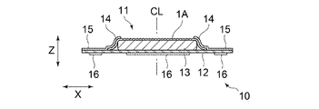
図1,図2には、第1実施形態の吸収性物品用の表面シート1A(以下、表面シート1Aとも言う)を用いた生理用ナプキン10が示されている。生理用ナプキン(以下、ナプキンとも言う)10は、肌当接面側に配された表面シート1A、非肌当接面側に配された裏面シート12、これら両シート1A,12間に配されたY方向に長い吸収体13を備えている。また、ナプキン10は、Y方向に沿う両側部10s,10sに、一対のサイドシート14,14が配されており、X方向外方に延出する一対のウイング部15,15が設けられている。ナプキン10は、図1に示すように、Y方向に延びる中心線CLに対して左右対称に形成されている。このように、ナプキン10においては、Y方向は着用者の前後方向に対応する製品の縦方向と同方向であり、X方向は製品の横方向と同方向でもある。
1 and 2 show a
尚、本明細書において、「肌当接面」とは、ナプキン10を構成する表面シートなどの各部材の表裏両面のうち、着用時に着用者の肌側に配される面であり、「非肌当接面」とは、表面シートなどの各部材の表裏両面のうち、着用時に着用者の肌側とは反対側に向けられる面である。
In the present specification, the “skin contact surface” is a surface disposed on the skin side of the wearer when worn, out of the front and back surfaces of each member such as a surface sheet constituting the
ナプキン10について、詳述すると、ナプキン10は、図1に示すように、表面シート1A、裏面シート12、これらシート1A,12間に配された吸収体13を備えた吸収性本体11を有している。吸収性本体11は、図1に示すように、ウイング部15,15の位置する領域である中央部A、生理用ナプキン10の着用時に中央部Aより着用者の腹側に配される前方部B、及びナプキン10の着用時に中央部Aよりも着用者の背中側に配される後方部Cに区分される。ナプキン10の着用時には、通常、吸収性本体11の中央部Aが、着用者の排泄部(膣口等)に対向配置される。言い換えれば、ウイング部15は、吸収性本体11の排泄対向領域(着用者の排泄部に対向する領域)に形成されている。
The
吸収性本体11を形成する表面シート1A及び裏面シート12それぞれは、図2に示すように、吸収体13の肌当接面側の全面及び非肌当接面側の全面を覆っており、吸収体13の周縁から延出する延出部分を有している。表面シート1Aは、図2に示すように、X方向の長さが裏面シート12のX方向の長さよりも短くなっている。一対のサイドシート14,14それぞれは、図1、図2に示すように、表面シート1Aの肌当接面側であって、表面シート1AのY方向に沿う側部全域に亘って配設固定されており、表面シート1Aの側部からX方向の外方に延出する延出部分を有している。ナプキン10においては、図1,図2に示すように、裏面シート12のX方向外方の延出部分とサイドシート14のX方向外方の延出部分とが、接着、融着等により固定されており、前方部B及び後方部Cよりも中央部Aにおいて大きくX方向外方に延出し、ウイング部15が形成されている。ナプキン10の裏面シート12の幅方向(X方向)中央部及びウイング部15の裏面シート12の延在部の非肌対向面上には、それぞれ粘着剤が塗布されて、ナプキン10をショーツ等の下着に固定するための固定部16が形成されている。尚、各サイドシート14は、そのX方向内方側(中心線CL側)の端部近傍に、Y方向に伸長状態の弾性部材を配設固定して、着用時に、その弾性部材の収縮力により、前記端部から所定幅の部分が表面シート1Aから離間する立体ギャザーを形成するようにしてもよい。
As shown in FIG. 2, each of the top sheet 1 </ b> A and the
また、ナプキン10には、表面シート1A及び吸収体13を一体的に圧縮してなるラウンド状のエンボス溝(不図示)が、Y方向に延びて、前方部Bから後方部Cまでに亘って延在している。エンボス溝(不図示)は、ナプキン10の前方部B、両側部10s,10s及び後方部Cに繋がる一条のラウンド状に形成されている。エンボス溝(不図示)は、表面シート1A及び吸収体13を、熱を伴うか又は伴わずに肌当接面側から圧縮することによって形成されている。
Further, the
本発明の吸収性物品用の表面シートは、図3に示すように、熱収縮した熱収縮性繊維を含む熱収縮繊維層1dを有し、複数のエンボス部2が形成されたシートである。詳述すると、ナプキン10の表面シート1Aは、熱収縮繊維層1dを有し、更に熱収縮繊維層1dに積層された非熱収縮性繊維からなる非熱収縮繊維層1uを有している。また、表面シート1Aにおいては、非熱収縮繊維層1uを肌当接面側に配し、熱収縮繊維層1dを非肌当接面側に配して形成されている。
As shown in FIG. 3, the surface sheet for absorbent articles of the present invention is a sheet having a heat-
表面シート1Aの熱収縮繊維層1dと非熱収縮繊維層1uとは、複数のエンボス部2により、間欠的に接合されている。具体的には、表面シート1Aは、熱収縮繊維層1dと非熱収縮繊維層1uとが、規則的に配された複数のエンボス部2により部分的に接合されて貼り合わされており、非肌当接面側の熱収縮繊維層1dの熱収縮性繊維が熱収縮されて形成されている。表面シート1Aには、図3に示すように、非熱収縮繊維層1uの肌当接面側からエンボスしたエンボス部2により凹陥した複数の凹部と、エンボスされていない非エンボス部に複数の凸部3が形成されている。
The heat-
本発明の表面シートは、複数のエンボス部2によって囲まれた大多角形領域BTを複数有し、エンボス部2は大多角形領域BTの頂部をなしている。また、本発明の表面シートは、複数の大多角形領域BTの頂部をなすエンボス部2によって囲まれた、大多角形領域BTよりも面積が小さい小多角形領域STを複数有し、エンボス部2は小多角形領域STの頂部もなしている。このように本発明の表面シートは、複数のエンボス部2によって囲まれた多角形領域(大多角形領域BT,小多角形領域ST)が形成されており、該多角形領域(大多角形領域BT,小多角形領域ST)内が非エンボス部となっている。具体的に説明すると、図3,図4に示すように、多角形領域は、複数のエンボス部2を頂部とし、これらによって囲まれた複数の相対的に面積の大きい大多角形領域BTと、隣接する複数の大多角形領域BTの頂部をなすエンボス部2を共通の頂部として囲まれた、大多角形領域BTよりも面積が小さい複数の小多角形領域STとを有している。このように、大多角形領域BTとこれに隣接する小多角形領域STとは、エンボス部2を共通の頂部としている。なお、本明細書において、「エンボス部2を頂部として」いる、や、「エンボス部2が頂点をなす」、とは、エンボス部2全体を頂点としている、という限定的な意味ではなく、エンボス部2の一部を頂点としている場合も含む。本実施形態の表面シート1Aでは、エンボス部2の一部が各多角形領域の頂点となっており、エンボス部2の頂点を除く残部が各多角形領域の外形をなす辺の一部となっている。また、「エンボス部によって囲まれた」という表現は、エンボス部の内側で構成される領域を意味するのではなく、エンボス部を含んで構成される領域を意味する。
The surface sheet of the present invention has a plurality of large polygonal regions BT surrounded by a plurality of embossed
詳述すると、本実施形態の表面シート1Aにおいては、大多角形領域BTは、図4に示すように、頂部をなす6つのエンボス部2によって囲まれており、外形が六角形の形状となっている。一方、小多角形領域STは、頂部をなす4つのエンボス部2によって囲まれており、外形が四角形の形状となっている。そして、第1方向(X方向)に関しては、隣り合う2つの大多角形領域BT,BTどうしが、各大多角形領域BTを構成している6つのエンボス部2の内の2つのエンボス部2(2つの後述する他エンボス部22)を共有し、該2つのエンボス2,2(2つの後述する他エンボス部22)を結ぶ辺によって互いに区分されている。また、第2方向(Y方向)に関しては、隣り合う2つの大多角形領域BT,BTどうしが、各大多角形領域BTを構成する6つのエンボス部6の内の1つのエンボス部2(後述する中間エンボス部21)を共有し、該1つのエンボス部2(後述する中間エンボス部21)によって互いに区分されている。また、1個の四角形の小多角形領域STが、それぞれ、4個の六角形の大多角形領域BTによって囲まれている。隣り合う小多角形領域STと各大多角形領域BTとは、6つのエンボス部6の内の2つのエンボス部2(後述する中間エンボス部21及び後述する他エンボス部22)を共有し、該2つのエンボス部2(後述する中間エンボス部21及び後述する他エンボス部22)によって互いに区分されている。したがって、表面シート1Aにおいては、小多角形領域STを構成する4つのエンボス部2は、全て、該小多角形領域STに隣接する4個の大多角形領域BTを構成するエンボス部2と共有している。
Specifically, in the
本発明の表面シートでは、図3,図4に示すように、複数の大多角形領域BTが第1方向(X方向)に沿って互いに隣接して配されて構成された大多角形領域列BTLが形成されている。また、本発明の表面シートでは、複数の小多角形領域STが第1方向(X方向)に沿って互いに隣接して配されて構成された小多角形領域列STLが形成されている。そして、大多角形領域列BTLと小多角形領域列STLとが、第1方向(X方向)と直交する第2方向(Y方向)に交互に配されている。即ち、第2方向(Y方向)に沿って、大多角形領域列BTL,小多角形領域列STL,大多角形領域列BTL,・・・と交互に配置されている。 In the surface sheet of the present invention, as shown in FIGS. 3 and 4, a large polygon region row BTL formed by arranging a plurality of large polygon regions BT adjacent to each other along the first direction (X direction) is provided. Is formed. Moreover, in the surface sheet of the present invention, a small polygon region row STL is formed in which a plurality of small polygon regions ST are arranged adjacent to each other along the first direction (X direction). The large polygon region row BTL and the small polygon region row STL are alternately arranged in a second direction (Y direction) orthogonal to the first direction (X direction). That is, along the second direction (Y direction), the large polygon region row BTL, the small polygon region row STL, the large polygon region row BTL,... Are alternately arranged.
図3に示すように、本発明の表面シートでは、各大多角形領域BT内には相対的に高さの高い高凸部31が形成されている。また、本実施形態の表面シート1Aにおいては、高凸部31が第1方向(X方向)に沿って複数配されて高凸部列31Lを構成している。一方、各小多角形領域ST内には、高凸部31よりも高さの低い低凸部32が形成されている。また、本実施形態の表面シート1Aにおいては、低凸部32が第1方向(X方向)に沿って複数配されて低凸部列32Lを構成している。そして、高凸部列31Lと低凸部列32Lとが、第1方向(X方向)と直交する第2方向(Y方向)に交互に配されている。即ち、第2方向(Y方向)に沿って、高凸部列31L,低凸部列32L,高凸部列31L,・・・と交互に配置されている。そして、高凸部列31Lの高凸部31と低凸部列32Lの低凸部32とは、表面シート1A上で千鳥状に配置されている。言い換えると、高凸部31と低凸部32とは、第1方向(X方向)と第2方向(Y方向)それぞれに対して斜めの方向に向かって交互に並んでいる。尚、高凸部31及び低凸部32に関しては、後で詳述する。
As shown in FIG. 3, in the surface sheet of the present invention, high
本実施形態の表面シート1Aにおいては、図3,図4に示すように、エンボス部2は、第2方向(Y方向)に関して最も近い位置にある2つの高凸部31,31どうしの間で、且つ、第1方向(X方向)に関して最も近い位置にある2つの低凸部32,32どうしの間に中間エンボス部21を有している。具体的には、第2方向(Y方向)に関して、最も近い高凸部列31L,31Lを構成する各高凸部のうち最も近い2つの高凸部31,31どうしの間で、且つ、該第2方向(Y方向)に関して最も近い高凸部列31L,31Lの間に位置する低凸部列32Lを構成する第1方向(X方向)に関して最も近い2つの低凸部32,32どうしの間に、1個の中間エンボス部21を有している。表面シート1Aにおいては、複数のエンボス部2は、2種類の形状のエンボスからなり、1つ目が中間エンボス部21であり、2つ目が中間エンボス部21を除く残りの他エンボス部22である。なお、本明細書において、「1個のエンボス部」とは、外形的に1つと見做せるエンボス形状のことをいい、該エンボス部が複数のドットや破線で構成されていても「1個のエンボス部」という。
In the
各中間エンボス部21は、図4に示すように、第1方向(X方向)に隣り合う四角形の小多角形領域ST,STにて、各小多角形領域STを構成する4つのエンボス部6の内の1つのエンボス部2として共有され、第2方向(Y方向)に隣り合う六角形の大多角形領域BT,BTにて、各多角形領域BTを構成する6つのエンボス部6の内の1つのエンボス部2として共有されている。従って、各中間エンボス部21は、第1方向(X方向)に関して最も近い2つの低凸部32,32どうしの中間位置に配されており、第2方向(Y方向)に関して最も近い2つの高凸部31,31どうしの中間位置に配されている。
As shown in FIG. 4, each of the intermediate
各中間エンボス部21は、図5,図6に示すように、第2方向(Y方向)に関して最も近い位置にある2つの大多角形領域BTの頂点をなしている頂部の中心点から各大多角形領域BTの外形を形成している辺に沿って延びる2方向延出形状部21aを備えている。上述したように、表面シート1Aにおいては、第2方向(Y方向)に隣り合う大多角形領域BT,BTは、1つの頂部を共有している。そして、表面シート1Aにおいては、四角形の各小多角形領域STの頂部は、全て、該小多角形領域STに隣接する六角形の大多角形領域BTの頂部と共有している。その為、第2方向(Y方向)に隣り合う2方向延出形状部21a,21aどうしが接しており、中間エンボス部21は、頂点から第2方向(Y方向)に隣り合う一方の六角形の大多角形領域BTの外形を形成している辺に沿って延びると共に、該頂点から第2方向(Y方向)に隣り合う他方の六角形の大多角形領域BTの外形を形成している辺に沿って延びる、4方向延出形状に、即ちX字形状に形成されている。X字形状の中間エンボス部21は、平面視して、頂点から4本の突出部21eが延出した形状である。該4本の突出部21eは各々同じ長さであり、X字形状の中間エンボス部21は、その中心点を通る第1方向(X方向)に平行な線及びその中心点を通る第2方向(Y方向)に平行な線各々に対して、線対称の形状となっている。
As shown in FIGS. 5 and 6, each of the intermediate
X字形状の中間エンボス部21では、第2方向(Y方向)における突出部21e同士の交差角度θ1(図5参照)は、表面シート1Aにおける肌との接触面積を低減させ、良好な肌触りを保ち、且つ、見た目の印象を良好にする観点から、好ましくは50°以上、特に好ましくは70°以上、そして、好ましくは170°以下、特に好ましく130°以下、より具体的には、50°以上170°以下であることが好ましく、70°以上130°以下であることが更に好ましい。尚、表面シート1Aにおいては、交差角度θ1は90°である。
In the X-shaped intermediate embossed
各他エンボス部22は、図4に示すように、1つの頂部を共有する小多角形領域ST及び第1方向(X方向)に隣り合う2つの大多角形領域BT,BTにおいて、該頂部の中心点である頂点から四角形の小多角形領域STの外形の一部を形成していると共に一方の六角形の大多角形領域BTの外形の一部を形成している辺に沿って延び、且つ該頂部の中心点である頂点から四角形の小多角形領域STの外形の一部を形成していると共に他方の六角形の大多角形領域BTの外形の一部を形成している辺に沿って延び、且つ一方の六角形の大多角形領域BTの外形の一部を形成していると共に他方の六角形の大多角形領域BTの外形の一部を形成している辺に沿って延びる3方向延出形状に、即ちY字形状に形成されている。Y字形状の他エンボス部22は、平面視して、頂部の中心点である頂点から3本の突出部22eが延出した形状である。該3本の突出部22eは各々同じ長さであり、Y字形状の他エンボス部22は、その中心点を通る第2方向(Y方向)に平行な線に対して、線対称の形状となっている。
As shown in FIG. 4, each other embossed
Y字形状の他エンボス部22では、突出部22e同士の交差角度θ2(図5参照)は、表面シート1Aにおける肌との接触面積を低減および良好な肌触りを保ち、且つ、見た目の印象を良好にする観点から、好ましくは50°以上、特に好ましくは70°以上、そして、好ましくは170°以下、特に好ましく130°以下、より具体的には、50°以上170°以下であることが好ましく、70°以上130°以下であることが更に好ましい。尚、表面シート1Aにおいては、交差角度θ2は130°である。
In the other embossed
表面シート1Aにおいては、X字形状の中間エンボス部21の4本の突出部21e及びY字形状の他エンボス部22の3本の突出部22eは、各々の長さが、表面シートにおける液の引き込み性および拡散性を高め、且つ情緒性の観点から、好ましくは0.5mm以上、更に好ましくは0.7mm以上、そして、好ましくは5.0mm以下、更に好ましくは4.0mm以下、より具体的には、0.5mm以上5.0mm以下であることが好ましく、0.7mm以上4.0mm以下であることが更に好ましい。尚、中間エンボス部21の4本の突出部21eは、表面シート1Aにおいては、頂部の中心点である頂点からの長さが互いに同じ長さとなっている。一方、他エンボス部22の3本の突出部22eは、表面シート1Aにおいては、頂点(頂部の中心点)からの長さが互いに同じ長さとなっている。しかし、当該形態に限定されるものではなく、長さが異なっていてもよい。例えば、他エンボス部22の3本の突出部22eのうち2本が同じ長さで1本が他の2本よりも長さが短いものであっても良い。なお、他エンボス部22の3本の突出部22eの内の1本の突出部22eは、表面シート1Aにおいては、第2方向(Y方向)に平行に配されている。
In the
各エンボス部2(中間エンボス部21及び他エンボス部22)は、良好な肌触りを維持しながら、表面シート1Aにおける液の引き込み性および拡散性を高める観点から、1個のエンボス部2(中間エンボス部21及び他エンボス部22の平均)の面積が、好ましくは1mm2以上、更に好ましくは1.5mm2以上、そして、好ましくは15mm2以下、更に好ましくは12mm2以下、より具体的には、1mm2以上15mm2以下であることが好ましく、1.5mm2以上12mm2以下であることが更に好ましい。
Each embossed part 2 (intermediate
各エンボス部2(中間エンボス部21及び他エンボス部22)は、第1方向(X方向)及び第2方向(Y方向)に、規則的に、それぞれ間隔を空けて別個独立して設けられている。各エンボス部2(中間エンボス部21及び他エンボス部22)は、表面シート1Aにおける液の引き込み性および拡散性を高め且つ良好な肌触りを保つ観点から、その密度が、好ましくは1個/cm2以上、更に好ましくは2個/cm2以上、そして、好ましくは32個/cm2以下、更に好ましくは16個/cm2以下、より具体的には、1個/cm2以上32個/cm2以下であることが好ましく、2個/cm2以上16個/cm2以下であることが更に好ましい。
Each embossed portion 2 (intermediate embossed
第1方向(X方向)に関して、最も近い位置にあるエンボス部2(中間エンボス部21及び他エンボス部22)どうしの間隔は、表面シート1Aにおける液の引き込み性および拡散性を高め、且つ見た目の印象と肌触りを良好に保つ観点から、好ましくは0.5mm以上、更に好ましくは1.0mm以上、そして、好ましくは5.0mm以下、更に好ましくは4.0mm以下、より具体的には、0.5mm以上5.0mm以下であることが好ましく、1.0mm以上4.0mm以下であることが更に好ましい。
The distance between the embossed portions 2 (the intermediate embossed
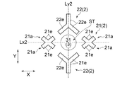
1個の六角形の大多角形領域BTは、図5に示すように、2個の中間エンボス部21と、4個の他エンボス部22とから形成されている。2個の中間エンボス部21は、平面視して、大多角形領域BTの重心を通る第2方向(Y方向)に平行に延びる仮想二等分線Ly1上に配されており、大多角形領域BTの重心を通る第1方向(X方向)に平行に延びる仮想二等分線Lx1に対して対称となるように配されている。4個の他エンボス部22は、2個の中間エンボス部21が配された頂部以外の、大多角形領域BTの頂部に配されている。第1方向(X方向)に関して最も近い2つの他エンボス部22,22どうしは、平面視して、第2方向(Y方向)に平行に延びる仮想二等分線Ly1に対して対称となるように配されている。そして、第2方向(Y方向)に関して最も近い2つの他エンボス部22,22どうしは、平面視して、第1方向(X方向)に平行に延びる仮想二等分線Lx1に対して対称となるように配されている。このように、1個の六角形の大多角形領域BTを構成するY方向に関して最も近い2つの他エンボス部22,22どうしは、仮想二等分線Lx1に対して、互いに逆向きになるよう配置されている。
As shown in FIG. 5, one hexagonal large polygonal region BT is formed by two intermediate
1個の四角形の小多角形領域STは、図6に示すように、2個の中間エンボス部21と、2個の他エンボス部22とから形成されている。2個の中間エンボス部21は、平面視して、小多角形領域STの重心を通る第1方向(X方向)に平行に延びる仮想二等分線Lx2上に配されており、小多角形領域STの重心を通る第2方向(Y方向)に平行に延びる仮想二等分線Ly2に対して対称となるように配されている。2個の他エンボス部22は、平面視して、第2方向(Y方向)に平行に延びる仮想二等分線Ly2上に配されており、第1方向(X方向)に平行に延びる仮想二等分線Lx2に対して対称となるように配されている。このように、1個の四角形の小多角形領域STを構成するY方向に関して最も近い2つの他エンボス部22,22どうしは、仮想二等分線Lx2に対して、互いに逆向きになるようにY字形状と逆Y字形状に配されている。
As shown in FIG. 6, one rectangular small polygon region ST is formed by two intermediate
上述したように、表面シート1Aにおいては、四角形の各小多角形領域STの頂部は、全て、該小多角形領域STに隣接する六角形の大多角形領域BTの頂部と共有している。その為、図4に示すように、第2方向に関して、Y字形状の他エンボス部22が第1方向(X方向)に等間隔で配されたY字形状の他エンボス部22の列と、逆Y字形状の他エンボス部22が第1方向(X方向)に等間隔で配された逆Y字形状の他エンボス部22の列との間に、X字形状の中間エンボス部21が第1方向(X方向)に等間隔で配された中間エンボス部21の列が配されている。このような3本のエンボス部列からなる配列が、第2方向(Y方向)に等間隔で配されている。そして、第1方向(X方向)に関しては、X方向に関して最も近い2つのY字形状の他エンボス部22,22どうしの中間に対応する位置にX字形状の中間エンボス部21が配されている。第2方向(Y方向)に関しては、Y方向に隣り合うY字形状の他エンボス部22と逆Y字形状の他エンボス部22とが、Y方向に平行に延びる仮想線上に配されている。
As described above, in the
エンボス部2(中間エンボス部21及び他エンボス部22)においては、表面シート1Aの構成繊維が圧密化されており、エンボスされていない部分に比べて、表面シート1Aの高さ(厚み)が最も低く(薄く)なっている。即ち、エンボス部2(中間エンボス部21及び他エンボス部22)による凹部の繊維密度は、エンボスされていない部分よりも高くなっており、表面シート1Aの中で最も高くなっている。また、エンボスの条件によっては、構成繊維が溶融固化してフィルム様になっている場合もある。このことから、エンボス部2(中間エンボス部21及び他エンボス部22)は表面シート1Aの硬さや排泄液の引き込み性に影響を与える。この観点から、表面シート全面積に対するエンボス部2の面積の比率、即ちエンボス化率は5%以上、30%以下であることが好ましく、特に、7%以上20%以下であることが好ましい。本発明の表面シートにおけるエンボスパターンによれば、このような低いエンボス化率としても、着用者の肌との接触面積を低くすることができる。
In the embossed part 2 (intermediate
以上のように形成された表面シート1Aでは、図4に示すように、六角形の大多角形領域BT内に形成される高凸部31は、平面形状が楕円の凸部であり、四角形の各小多角形領域ST内に形成される低凸部32は、平面形状が円形の凸部となっている。
In the
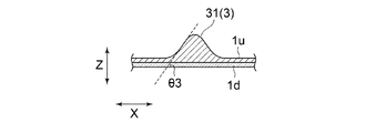
高凸部31の厚み方向(Z方向)の頂点における高さhb(図7参照)は、表面シート1Aの良好は肌触りを高め、且つ繊維の密度勾配を強化して液の引き込み性を高める観点から、好ましくは1.0mm以上、更に好ましくは1.5mm以上、そして、好ましくは7.0mm以下、更に好ましくは5.0mm以下、より具体的には、1.0mm以上7.0mm以下であることが好ましく、1.5mm以上5.0mm以下であることが更に好ましい。高凸部31の高さhbは、高凸部の最大高さであるが、概ね、大多角形領域BTの重心に対応する位置での高さでもある。高さhbは、後述する表面シート1Aの繊維密度の比率(1)と同様にして測定する。
また、高凸部31の底面からの隆起角度θ3(図8参照)は、多量の経血時においても、肌に触れる部分に経血を残し難くする観点から、好ましくは70°以上、更に好ましくは75°以上、そして、好ましくは90°以下、更に好ましくは85°以下、より具体的には、70°以上90°以下であることが好ましく、75°以上85°以下であることが更に好ましい。隆起角度θ3は、上記高さhbを測定する際に同時に測定する。
The height hb (see FIG. 7) at the apex in the thickness direction (Z direction) of the high
Further, the rising angle θ3 (see FIG. 8) from the bottom surface of the high
低凸部32の厚み方向(Z方向)の頂点における高さhs(図9参照)は、表面シート1Aの良好な肌触り感を高め、且つ繊維の密度勾配を強化して液の引き込み性を高める観点から、好ましくは0.4mm以上、更に好ましくは0.8mm以上、そして、好ましくは4.5mm以下、更に好ましくは2.5mm以下、より具体的には、0.4mm以上4.5mm以下であることが好ましく、0.8mm以上2.5mm以下であることが更に好ましい。低凸部32の高さhsは、低凸部32の最大高さであるが、小多角形領域STにおける重心に対応する位置での高さでもある。高さhsは、後述する表面シート1Aの繊維密度の比率(1)と同様にして測定する。
また、低凸部32の底面からの隆起角度θ4(図9参照)は、多量の経血時においても、肌に触れる部分に経血を残し難くする観点から、好ましくは25°以上、更に好ましくは30°以上、そして、好ましくは70°以下、更に好ましくは65°以下、より具体的には、25°以上70°以下であることが好ましく、30°以上65°以下であることが更に好ましい。隆起角度θ4は、上記高さhsを測定する際に同時に測定する。
The height hs (see FIG. 9) at the apex in the thickness direction (Z direction) of the low
Further, the rising angle θ4 (see FIG. 9) from the bottom surface of the low
表面シート1Aにおいては、立体ドーム構造の高凸部31は、その繊維密度が、立体ドーム構造の低凸部32の繊維密度よりも低くなっており、特にそのZ方向の頂点(高さhbの基準点)において、表面シート1Aの中で最も低くなっている。立体ドーム構造の低凸部32は、その繊維密度が、そのZ方向の頂点(高さhsの基準点)において、低凸部32の中で最も低くなっている。このように、高凸部31のZ方向の頂点(高さhbの基準点)における繊維密度は、低凸部32のZ方向の頂点(高さhsの基準点)における繊維密度よりも低くなっている。したがって、排泄液は、着用者の肌に接触している高凸部31から低密度部へと移行し易くなっている。更に、第1方向(X方向)に隣接する低凸部32,32どうしの間に位置し、かつ、第2方向(Y方向)に隣接する高凸部31,31どうしの間に位置する中間エンボス部21が存在することによって、中間エンボス部21周辺の繊維密度が高められている。このために、肌へのクッション性を与える最も密度の低い高凸部31へ排出された排泄液は、表面から下方へと浸透しやすくなっているので、急速に表面シート1A上をX方向及びY方向へと拡散されることなく、液モレが抑制される。
In the
低凸部32のZ方向の頂点(高さhsの基準点)における繊維密度dsに対する、高凸部31のZ方向の頂点(高さhbの基準点)における繊維密度dbの比率(db/ds)は、排泄された体液の引き込み性を強化する観点から、好ましくは1.2倍以上、更に好ましくは1.5倍以上、そして、好ましくは3.0倍以下、更に好ましくは2.5倍以下、より具体的には、1.2倍以上3.0倍以下であることが好ましく、1.5倍以上2.5倍以下であることが更に好ましい。
Ratio (db / ds) of the fiber density db at the vertex in the Z direction (reference point for height hb) of the high
表面シート1Aの繊維密度の比率は、以下に記載する2つの方法(1)及び(2)のいずれかを使用して計測することができる。
(1)表面シート1Aの坪量が略均一(一様)である場合(あるいは略均一と判断できる場合)には、表面シート1Aの切断面の高さ(厚み)を計測する。
(2)表面シート1Aの坪量が不均一である場合(あるいは不均一と判断できる場合)には、表面シート1Aの切断面における繊維間の平均距離を計測する。
The ratio of the fiber density of the
(1) When the basis weight of the
(2) When the basis weight of the
ここで、表面シート1Aの坪量が略均一であるか否かの判断は、次の通り行う。
表面シート1Aから、Y方向10cmX方向10cmのサイズのカットサンプルを10個以上の取り出し、各々の坪量を計測した際に、標準偏差σの3倍値(3σ)が平均μの10%以内であり、外観上繊維ムラが見られなければ、略均一と判断する。ただし、微小領域で組成が異なっている等、様々な要因を考慮し、総合的に判断することが好ましい。
Here, the determination as to whether the basis weight of the
When 10 or more cut samples having a size of 10 cm in the Y direction and 10 cm in the X direction are taken out from the
まず、(1)の方法について説明する。
平面視における表面シート1Aから、高凸部31の重心(Z方向の頂点)と両端の2個のエンボス部2(中間エンボス部21)とを通る直線で切断して高凸部31測定用サンプルを作成する。同様に、低凸部32の重心(Z方向の頂点)と両端の2個のエンボス部2(2個の中間エンボス部21或いは2個の他エンボス部22)とを通る直線で切断して低凸部32測定用サンプルを作成する。この際、切断により各測定用サンプルの高さの減少等をなるべく起こさないように留意する。
First, the method (1) will be described.
A sample for measuring the high
得られた各測定用サンプルの断面の計測は、日本電子株式会社製の電子顕微鏡 JCM−5100を使用し、スパッター時間30秒(Pt)、加速電圧10KVの条件で行うが、測定用サンプルの両端のエンボス部2の少なくとも一方が撮影されるか、あるいは複数枚の画像を組み合わせて前記エンボス部2がわかる状況とし、撮影画像から各測定用サンプルの高さ(厚み)を計測する。尚、画像の計測は、印刷物あるいはPC画面上のどちらを使用して行ってもよい。
(1)の方法においては、高凸部31測定用サンプルの中央部の高さhb(厚み)を、低凸部32測定用サンプルの中央部の高さhs(厚み)で除して密度の比率(db/ds)とする。
The cross section of each measurement sample obtained was measured using an electron microscope JCM-5100 manufactured by JEOL Ltd. under the conditions of a sputtering time of 30 seconds (Pt) and an acceleration voltage of 10 KV. At least one of the
In the method (1), the height hb (thickness) of the central portion of the sample for measuring the high
次に、(2)の方法について説明する。
(1)の方法と同様に断面を計測するが、(1)の方法で行う測定に加えて、各測定用サンプルの断面を拡大倍率500〜1000倍で撮影する。拡大撮影画像各々の対象測定部位(各測定用サンプルの中央部)で且つ幅方向(平面方向)に繊維本数が3〜7本の領域において、画像解析装置(NEXUS製NEWQUBE ver.4.20)を使用して、繊維の最近接重心間距離を求める。
上記計測においては、高さ(厚み)方向に略全体的に計測し、且つ最近接重心間距離の重複が生じないようにする。また、断面については、少なくとも3箇所、好ましくは5箇所、より好ましくは10箇所計測し、その平均値を用いる。
(2)の方法においては、高凸部31測定用サンプルの中央部の最近接重心間距離を、低凸部32測定用サンプルの中央部の最近接重心間距離で除して密度の比率(db/ds)とする。
Next, the method (2) will be described.
The cross section is measured in the same manner as in the method (1). In addition to the measurement performed by the method (1), the cross section of each measurement sample is photographed at an enlargement magnification of 500 to 1000 times. In the region where the number of fibers is 3 to 7 in the width direction (plane direction) at the target measurement site (center portion of each measurement sample) of each of the magnified images, an image analyzer (NEWQBE ver. 4.20 made by NEXT) Is used to find the distance between the nearest centers of gravity of the fibers.
In the above measurement, measurement is performed almost entirely in the height (thickness) direction, and the closest distance between the centers of gravity is not caused to overlap. Moreover, about a cross section, it measures at least 3 places, Preferably 5 places, More preferably, 10 places, The average value is used.
In the method of (2), the distance ratio between the nearest centroids at the center of the sample for measuring the high
上述した本発明の吸収性物品用の表面シートに用いた生理用ナプキン10の形成材料について説明する。
先ず、表面シート1Aの形成材料について説明する。
非熱収縮性繊維からなる非熱収縮繊維層1uとしては、例えば、カード法によって形成されたウェブや嵩高な不織布が好ましく用いられる。嵩高な不織布としては、表面シート1Aに所望の密度勾配を持たせることが可能であること、また表面シート1Aに良好な風合いをもたらすことが可能であるとの観点から、エアスルー不織布、エアレイド不織布、レジンボンド不織布が好ましく用いられる。カード法によって形成されたウェブとは、不織布化される前の状態の繊維集合体のことである。つまり、不織布を製造する際に用いられるカードウェブに加えられる後処理、例えばエアスルー法やカレンダー法による加熱融着処理が施されていない状態にある、繊維同士が極めて緩く絡んでいる状態の繊維集合体のことである。カード法によって形成されたウェブを非熱収縮繊維層1uとして用いる場合には、非熱収縮繊維層1uと熱収縮繊維層1dとを接合させると同時に又は接合させた後、非熱収縮繊維層1u中の繊維同士を熱融着させる。
非熱収縮繊維層1uの構成繊維である非熱収縮性繊維としては、実質的に熱収縮性を有しないものか、下層(熱収縮繊維層)よりも熱収縮温度が高い繊維であれば、通常、生理用ナプキン、使い捨ておむつ等の吸収性物品に用いられるものを、特に制限なく用いることができる。
非熱収縮繊維層1uの坪量は、充分な密度勾配を形成する観点及び表面シート1Aの肌触りを良好にする観点から、好ましくは10g/m2以上、更に好ましくは15g/m2以上、そして、好ましくは50g/m2以下、更に好ましくは40g/m2以下、より具体的には、10g/m2以上50g/m2以下であることが好ましく、15g/m2以上40g/m2以下であることが更に好ましい。
The material for forming the
First, a material for forming the
As the non-heat-
As the non-heat-shrinkable fiber that is a constituent fiber of the non-heat-
The basis weight of the non-heat-
熱収縮性繊維を含む熱収縮繊維層1dとしては、カード法によって形成されたウェブや熱収縮性を有する不織布を用いることができる。
熱収縮繊維層1dの構成繊維の熱収縮性繊維としては、熱可塑性ポリマー材料からなり且つ熱収縮性を有するものが好適に用いられる。そのような繊維の例としては、潜在捲縮性繊維が挙げられる。潜在捲縮性繊維は、加熱される前においては、従来の不織布用の繊維と同様に取り扱うことができ、且つ所定温度で加熱することによって螺旋状の捲縮が発現して収縮する性質を有する繊維である。熱収縮繊維層1d中の熱収縮性繊維の含有割合は40質量%以上100質量%以下であることが好ましい。
As the heat-
As the heat-shrinkable fibers of the constituent fibers of the heat-
熱収縮性繊維である潜在捲縮性繊維は、例えば、収縮率の異なる2種類の熱可塑性ポリマー材料を成分とする偏心芯鞘型又はサイド・バイ・サイド型の複合繊維からなる。その例としては、特開平9−296325号公報や特許第2759331号公報に記載のものが挙げられる。熱収縮繊維層1dは、例えば、このような潜在捲縮性繊維を含ませておき、非熱収縮繊維層1uとの熱融着と同時に又はその後に、加熱により該繊維の捲縮を発現させ、収縮させることができる。熱収縮繊維層1dの坪量は、好ましくは10g/m2以上、更に好ましくは15g/m2以上、そして、好ましくは50g/m2以下、更に好ましくは40g/m2以下、より具体的には、10g/m2以上50g/m2以下であることが好ましく、15g/m2以上40g/m2以下であることが更に好ましい。
The latent crimpable fiber, which is a heat-shrinkable fiber, is composed of, for example, an eccentric core-sheath type or side-by-side type composite fiber composed of two types of thermoplastic polymer materials having different shrinkage rates. Examples thereof include those described in JP-A-9-296325 and Japanese Patent No. 2759331. The heat-
本発明の一実施形態である表面シート1Aは、例えば、非熱収縮性繊維を含む非熱収縮繊維層1uを上層にし、収縮前の熱収縮性繊維からなる熱収縮繊維層1dを下層にして重ね合わせ、複数のエンボス部2(中間エンボス部21及び他エンボス部22)により所定の規則正しいパターンで部分的に貼り合わせると同時に又は両者を貼り合わせた後に、熱を加えて、下層の熱収縮繊維層1dを水平方向に熱収縮させることにより形成される。非熱収縮繊維層1u及び熱収縮繊維層1dがエンボス部2(中間エンボス部21及び他エンボス部22)により間欠的に貼り合わされて一体化されているために、熱収縮繊維層1dが熱収縮すると、非熱収縮繊維層1uもつられて縮もうとして歪が生じる。この歪が非熱収縮繊維層1u側に凸状に隆起し立体ドーム形状の凸部3が複数形成される。エンボス部2による貼り合わせ(熱融着)は、例えば、X字形状の中間エンボス部21及びY字形状の他エンボス部22の配置に対応するように、複数の略X字形状及び略Y字形状の断面のエンボスピンが所定のパターンで配設されたエンボス面(エンボスロールの周面等)を、非熱収縮繊維層1uと熱収縮繊維層1dとの積層体における非熱収縮繊維層1u側から圧接させ、各エンボスピンに熱圧された部位における非熱収縮繊維層1u及び熱収縮繊維層1dを溶融させて行う。
A
熱収縮繊維層1dの熱収縮は、例えば、熱収縮繊維層1dを1種又は複数種の熱収縮性繊維のみから構成するか又は熱収縮繊維層1d中に1種又は複数種の熱収縮性繊維を含ませておき、非熱収縮繊維層1uと熱収縮繊維層1dとを貼り合わせると同時に又は非熱収縮繊維層1uと熱収縮繊維層1dとを貼り合わせた後に、熱収縮繊維層1dを加熱処理することにより行われる。
The heat shrinkage of the heat-
熱収縮の際、表面シート1Aにおいては、6個のエンボス部2(2個の中間エンボス部21及び4個の他エンボス部22)で囲まれた大多角形領域BTは、最も領域が広く空いているので、6個のエンボス部2で抑制され難く、隆起し易く、最も高い高凸部31となる。また、4個のエンボス部2(2個の中間エンボス部21及び2個の他エンボス部22)で囲まれた小多角形領域STは狭いので、熱収縮繊維層1dを水平方向に熱収縮させても、隆起が4個のエンボス部2で抑制されるので、高凸部31よりも高さの低い低凸部32となる。
At the time of heat shrinkage, in the
上述した方法で非熱収縮繊維層1u及び熱収縮繊維層1dを貼り合わせて形成された表面シート1Aは、その坪量が、好ましくは20g/m2以上、更に好ましくは35g/m2以上、そして、好ましくは100g/m2以下、更に好ましくは80g/m2以下、より具体的には、20g/m2以上100g/m2以下であることが好ましく、35g/m2以上80g/m2以下であることが更に好ましい。
The
また、吸収性本体11を構成する裏面シート12、吸収体13及びサイドシート14としては、それぞれ、通常、生理用ナプキン、使い捨ておむつ等の吸収性物品に用いられるものであれば、特に制限なく用いることができる。例えば、裏面シート12としては、液不透過性又は撥水性の樹脂フィルムや樹脂フィルムと不織布の積層体等を用いることができる。例えば、吸収体13としては、パルプ繊維等の繊維の集合体(不織布であっても良い)又はこれに吸水性ポリマーの粒子を保持させてなる吸収性コアを、透水性の薄紙や不織布からなるコアラップシートで被覆したもの等を用いることができる。例えば、サイドシート14としては、裏面シート3と同様のものを用いることができる。
Moreover, as the
表面シート1A、裏面シート3、吸収体4及びサイドシート5の固定には、通常、使い捨ておむつ等の吸収性物品に用いられる接着剤やヒートエンボス、超音波エンボス、高周波エンボス等の融着手段が用いられる。
For fixing the
上述した本発明の実施形態の表面シート1Aを生理用ナプキンに使用した際の作用効果について説明する。
表面シート1Aは、図3に示すように、高さの高い複数の高凸部31と、高さの低い複数の低凸部32とを有している。その為、生理用ナプキン10の着用時において、高凸部31は肌と当接するが、高凸部31の間に配された低凸部32は肌と当接し難い。よって、表面シート1Aを生理用ナプキン10に用いると、不織布本来の柔らかい風合いを維持しながら着用者の肌との接触面積をさらに低減することができ、べたつき感やムレ感をさらに低減することができる。また、第1実施形態の表面シート1Aは、着用者の肌との接触面積をさらに低減することができ、肌へのダメージを減らすことができる。尚、表面シート1Aと着用者の肌との接触面積は45%以下、特に42%以下であることが上述の理由から好ましい、また下限値としては25%以上、特に30%以上が好ましい。
The effect at the time of using the
As shown in FIG. 3, the top sheet 1 </ b> A has a plurality of high
また、表面シート1Aは、図3に示すように、高凸部31より高さの低い低凸部32の配置において工夫をしている。具体的には、複数の大多角形領域BTが第1方向(X方向)に沿って互いに隣接して配されて構成された大多角形領域列BTLと、複数の小多角形領域STLが第1方向(X方向)に沿って互いに隣接して配されて構成された小多角形領域列STLとが、第1方向(X方向)と直交する第2方向(Y方向)に交互に配されている。その為、各小多角形領域列STLを構成する各小多角形領域STL内に形成される低凸部32が、着用によって装着圧が加わったとしても、規則的に配された大多角形領域BT内に形成される高凸部31によって保護され、厚み方向に潰れ難くなっている。しかも、図15に示すような、特許文献2の大小凸部のパターンでは、低凸部330、330の間に大凸部320、320の影響を受ける領域が存在するのに対して、表面シート1Aでは、低凸部列32L内で隣り合った低凸部32の間、特に中間位置に、高凸部31の影響を受け易い領域が存在しない。このため、小多角形領域列STLが複数の低凸部32と、その間に存在するより高さの低い領域とからなるので、空気や蒸気の通路が確保され、ムレ抑制に有効であるとともに、第2方向(Y方向)への液拡散が抑制され易くなっている。
Further, as shown in FIG. 3, the top sheet 1 </ b> A is devised in the arrangement of the low
また、表面シート1Aは、図3に示すように、高凸部31より高さの低い低凸部32の配置において更に工夫をしている。具体的には、ナプキン10の横方向に相当する第1方向(X方向)に沿って形成した高凸部列32Lと低凸部列33Lを、縦方向に相当する第2方向(Y方向)に交互に配置する。そして、縦方向(Y方向)に関して最も近い2つの高凸部31,31どうしの中間部に中間エンボス部21を、低凸部列32L内に位置するように配置している。このために、第2方向(Y方向)に関して最も近い2つの高凸部31,31どうしの間には高い尾根部が存在せずに、互いの高凸部31,31どうしは低い中間エンボス部21で離間されるため、低い繊維密度である高凸部31を伝わってY方向へ排泄液が迅速に拡散されることが抑制される。また、中間エンボス部21によって、表面シート1Aに繊維の密度勾配が付与されて液の引き込み性が高まるとともに、べたつき感やムレ感の低減効果を奏する。一方、第1方向(X方向)に関して最も近い2つの低凸部32,32どうしは、中間エンボス部21の存在によって、高凸部31とは、縦方向(Y方向)及び横方向(X方向)の双方に対して斜めの方向に配置されることとなる。このために、低凸部32は、着用によって装着圧が加わり、高凸部31が厚み方向に潰れても、その影響を受けにくい。一方、中間エンボス部21と低凸部32で囲まれた高凸部31は、装着圧に対する抵抗力があるので、潰れにくい。このようなメカニズムによって、装着中の着用者の肌と表面シート1Aとの接触面積は小さく保つことが容易となるとともに、低凸部列32Lによる通気路が確保されるので、ベタつきにくく、ムレが抑制され易い。
Further, as shown in FIG. 3, the top sheet 1 </ b> A is further devised in the arrangement of the low
また、表面シート1Aにおいては、複数の低凸部32が、それぞれ、図4に示すように、第1方向(X方向)に隣り合う中間エンボス部21を介して、一列に配置されている。このように、最も近い位置にある低凸部32,32どうしの間に、より高さの低い中間エンボス部21が存在し、低凸部列32Lが形成されていることにより、低凸部列33Lに沿った空気及び水蒸気の流れを確保することができるので、ナプキン10の着用中にムレを抑制することが容易となる。中間エンボス部21が1個のみで形成されていると、より効果が高い。
In the
また、表面シート1Aは、図3に示すように、非熱収縮繊維層1uを肌当接面側に配し、熱収縮繊維層1dを非肌当接面側に配して形成されている。その為、収縮によって繊維密度が高まった熱収縮繊維層1dへ向かって、排泄された体液が肌当接面側から非肌当接面側に毛管力により引き込まれて速やかに移行し、ムレ低減効果を奏する。
Further, as shown in FIG. 3, the
次に、本発明の表面シートの第2実施形態としての表面シート(以下、「表面シート1B」ともいう。)について、図10に基づいて説明する。
第2実施形態の表面シート1Bについては、第1実施形態の表面シート1Aと異なる点について説明する。特に説明しない点は、表面シート1Aの説明が適宜適用される。また、表面シート1Bの効果については、上述した表面シート1Aの効果と異なる点について説明し、特に説明しない点は、上述した表面シート1Aの効果と同様である。
Next, a surface sheet (hereinafter also referred to as “
About the
表面シート1Bにおいては、図10に示すように、各小多角形領域STが六角形に形成され、各大多角形領域BTが六角形に形成されている。そして、六角形の各小多角形領域STの頂部は、全て、該小多角形領域STに隣接する六角形の大多角形領域BTの頂部と共有している。1個の六角形の大多角形領域BTは、2個の中間エンボス部21と、4個の他エンボス部22とから形成されている。1個の六角形の小多角形領域STは、2個の中間エンボス部21と、2個の他エンボス部22とから形成されている。表面シート1Bの中間エンボス部21は、第2方向(Y方向)に関して最も近い位置にある2つの大多角形領域BT,BTの頂点(頂部の中心点)から各大多角形領域BTの外形を形成している辺に沿って延びる2方向延出形状部21aを備えている。表面シート1Bの各中間エンボス部21は、2個の2方向延出形状部21aを備えている。一方の2方向延出形状部21aは、前記頂点(頂部の中心点)から第2方向(Y方向)に隣り合う一方の六角形の大多角形領域BTの外形を形成している辺に沿って突出部21eが延出したV字状に形成されている。他方の2方向延出形状部21aは、前記頂点(頂部の中心点)から第2方向(Y方向)に隣り合う他方の六角形の大多角形領域BTの外形を形成している辺に沿って突出部21eが延出した逆V字状に形成されている。表面シート1Bの各中間エンボス部21は、V字状の2方向延出形状部21aと、逆V字状の2方向延出形状部21aと、これらの中間位置に独立して配された矩形状の独立エンボス部21bとからなる。したがって、本実施形態では1つの中間エンボス部21が3個のエンボス単位から構成されているが、各エンボス単位間の距離を十分に小さくする、具体的には、2mm以下とすることで、1個の中間エンボス部21と見做すことができる。1個の中間エンボス部21における各エンボス単位間の好ましい距離は1mm以下、特に0.5mm以下である。
In the
表面シート1Bの長所は、小多角形領域STの面積を大きくすることが容易となるので、表面シート1Bと肌との接触面積を第1実施形態の表面シート1Aよりも小さくすることが容易となる点である。一方で、第1実施形態の表面シート1Aでは、第2方向(Y方向)に隣り合う2方向延出形状部21a,21aどうしが接して、中間エンボス部21が1つのX字形状のエンボスから構成されているので、エンボス化率を低くすることができており、液の引き込み性や風合いの点で優れる。
The advantage of the
次に、本発明の表面シートの第3実施形態としての表面シート(以下、「表面シート1C」ともいう。)について、図11に基づいて説明する。
第3実施形態の表面シート1Cについては、第1実施形態の表面シート1Aと異なる点について説明する。特に説明しない点は、表面シート1Aの説明が適宜適用される。また、表面シート1Cの効果については、上述した表面シート1Aの効果と異なる点について説明し、特に説明しない点は、上述した表面シート1Aの効果と同様である。
Next, a surface sheet (hereinafter also referred to as “
Regarding the
表面シート1Cにおいては、図11に示すように、各小多角形領域STが六角形に形成され、各大多角形領域BTが六角形に形成されている。そして、六角形の各小多角形領域STの頂部は、全て、該小多角形領域STに隣接する六角形の大多角形領域BTの頂部と共有している。1個の六角形の大多角形領域BTは、2個の中間エンボス部21と、4個の他エンボス部22とから形成されている。1個の六角形の小多角形領域STは、2個の中間エンボス部21と、2個の他エンボス部22とから形成されている。表面シート1Cの中間エンボス部21は、第2方向(Y方向)に関して最も近い位置にある2つの大多角形領域BT,BTの頂点(頂部の中心点)から各大多角形領域BTの外形を形成している辺に沿って延びる2方向延出形状部21aを備えている。表面シート1Cの各中間エンボス部21は、2個の2方向延出形状部21aを備えている。一方の2方向延出形状部21aは、前記頂点(頂部の中心点)から第2方向(Y方向)に隣り合う一方の六角形の大多角形領域BTの外形を形成している辺に沿って突出部21eが延出したV字状に形成されている。他方の2方向延出形状部21aは、前記頂点(頂部の中心点)から第2方向(Y方向)に隣り合う他方の六角形の大多角形領域BTの外形を形成している辺に沿って突出部21eが延出した逆V字状に形成されている。表面シート1Cの各中間エンボス部21は、V字状の2方向延出形状部21aと、逆V字状の2方向延出形状部21aと、これらを結ぶY方向に平行な矩形状の連結エンボス部21cとからなる。
In the
表面シート1Cの長所は、小多角形領域STの面積を大きくすることが容易となるので、表面シート1Cと肌との接触面積を第1実施形態の表面シート1Aよりも小さくすることが容易となる点である。一方で、第1実施形態の表面シート1Aでは、第2方向(Y方向)に隣り合う2方向延出形状部21a,21aどうしが接して、中間エンボス部21が1つのX字形状のエンボスから構成されているので、エンボス化率を低くすることができており、液の引き込み性や風合いの点で優れる。
The advantage of the
本発明の吸収性物品用の表面シートは、上述の第1実施形態の表面シート1A乃至第3実施形態の表面シート1Cに何ら制限されるものではなく、適宜変更可能である。また、上述の表面シート1A乃至表面シート1Cにおける各構成要件は、本発明の趣旨を損なわない範囲で、適宜組み合わせて実施できる。
The top sheet for absorbent articles of the present invention is not limited to the
例えば、上述の表面シート1Aは、非熱収縮繊維層1uを肌当接面側に配し、熱収縮繊維層1dを非肌当接面側に配して形成された2層構造であるが、熱収縮繊維層1dのみからなる1層構造であってもよい。また、熱収縮繊維層1dの両面に非熱収縮繊維層1uを積層して3層構造としてもよい。
For example, the
また、上述した第1実施形態の表面シート1A乃至第3実施形態の表面シート1Cでは、いずれも、中間エンボス部21の突出部21e及び他エンボス部22の突出部22eが直線より構成される矩形であったが、これに代えて、図12,図13に示すような曲線的な形状を採用しても良い。具体的には、図12に示すX字形状の中間エンボス部21においては、隣接する2本の突出部21eからなるV字状の輪郭が、それぞれ、中間エンボス部21の頂点(頂部の中心点)に向かって内方に凸の湾曲形状となっている。また、図12に示すY字形状の他エンボス部22においては、隣接する2本の突出部22eからなるV字状の輪郭が、それぞれ、他エンボス部22の頂点(頂部の中心点)に向かって内方に凸の湾曲形状となっている。次に、図13に示すX字形状の中間エンボス部21においては、4本の突出部21eの輪郭が、それぞれ、小多角形領域ST或いは大多角形領域BTに向かって外方に凸の曲線形状となっている。また、図13に示すY字形状の他エンボス部22においては、3本の突出部22eの輪郭が、それぞれ、小多角形領域ST或いは大多角形領域BTに向かって外方に凸の曲線形状となっている。特に、図13に示すような曲線形状を有する中間エンボス部21及び他エンボス部22であることが、エンボス部2が存在する位置において凸部3の裾部分が区画されて、エンボス部2が存在しない部分を介して隣の多角形領域における凸部や、凸部と凸部の間の領域に高さの影響を及ぼし難くなるので、上述した効果を奏することができ、更に視覚的な観点からも好ましい。図12,図13に示すような曲線形状を有する中間エンボス部21及び他エンボス部22である場合、中間エンボス部21を構成する突出部21e同士の交差角度θ1は、突出部21e同士の内側交点部分からそれぞれの突出部21eの先端へ向かって引いた2本の仮想線のなす角度である。また、他エンボス部22を構成する突出部22e同士の交差角度θ2は、突出部22e同士の内側交点部分からそれぞれの突出部22eの先端へ向かって引いた2本の仮想線のなす角度である。尚、交差角度θ1,θ2の好ましい角度については、前述したとおりである。
Moreover, in the
上述した実施形態に関し、さらに以下の吸収性物品用の表面シートを開示する。
・ 熱収縮した熱収縮性繊維を含む熱収縮繊維層を有し、複数のエンボス部
が形成された吸収性物品用の表面シートであって、複数の前記エンボス部によって囲まれた大多角形領域を複数有し、該エンボス部は該大多角形領域の頂部をなしており、複数の前記大多角形領域の頂部をなす前記エンボス部によって囲まれた、該大多角形領域よりも面積が小さい小多角形領域を複数有し、該エンボス部は該小多角形領域の頂部もなしており、各前記大多角形領域内には高凸部が形成され、各前記小多角形領域内には、該高凸部よりも高さの低い低凸部が形成されており、複数の前記大多角形領域が第1方向に沿って互いに隣接して配されて構成された大多角形領域列と、複数の前記小多角形領域が該第1方向に沿って互いに隣接して配されて構成された小多角形領域列とが、該第1方向と直交する第2方向に交互に配されている吸収性物品用の表面シート。
〔2〕 前記高凸部が前記第1方向に沿って複数配して構成された高凸部列と、前記低凸部が該第1方向に沿って複数配して構成された低凸部列とが、該第1方向と直交する第2方向に交互に配されており、前記エンボス部は、前記第2方向に関して最も近い位置にある2つの前記高凸部どうしの間で、且つ、前記第1方向に関して最も近い位置にある2つの前記低凸部どうしの間に、中間エンボス部を有している前記〔1〕記載の吸収性物品用の表面シート。
〔3〕 前記中間エンボス部が、前記第1方向に関して最も近い位置にある2つの前記低凸部どうしの間に1個だけ存在している、前記〔2〕記載の吸収性物品用の表面シート。
〔4〕 前記小多角形領域を構成する前記エンボス部は、全て、該小多角形領域に隣接する複数の前記大多角形領域を構成する前記エンボス部と共有されている前記〔1〕乃至〔3〕記載の表面シート。
〔5〕 前記大多角形領域が六角形に形成されており、前記小多角形領域が四角形に形成されている前記〔1〕乃至〔4〕の何れか1つに記載の表面シート。
〔6〕 前記中間エンボス部は、前記第2方向に関して最も近い位置にある2つの前記大多角形領域の頂部の中心点から各該大多角形領域の外形を形成している辺に沿って延びる2方向延出形状部を備えている前記〔2〕乃至〔5〕の何れか1つに記載の表面シート。
〔7〕 前記第2方向に関して最も近い位置にある2つの前記大多角形領域は、1つの頂部を共有しており、前記中間エンボス部は、該頂部の中心点から一方の前記大多角形領域の外形を形成している辺に沿って延びると共に、該頂部の中心点から他方の前記大多角形領域の外形を形成している辺に沿って延びる4方向延出形状に形成されている前記〔2〕乃至〔6〕の何れか1つに記載の表面シート。
〔8〕 前記中間エンボス部を除く前記エンボス部は、1つの頂部を共有する前記小多角形領域及び前記第1方向に隣り合う2つの前記大多角形領域において、該頂部の中心点から該小多角形領域の外形を形成していると共に一方の前記大多角形領域の外形を形成している辺に沿って延び、且つ該頂部の中心点から該小多角形領域の外形を形成していると共に他方の前記大多角形領域の外形を形成している辺に沿って延び、且つ一方の前記大多角形領域の外形を形成していると共に他方の前記大多角形領域の外形を形成している辺に沿って延びる3方向延出形状に形成されている前記〔2〕乃至〔7〕の何れか1つに記載の表面シート。
〔9〕 前記エンボス部が、X字形状の前記中間エンボス部及びY字形状の前記他エンボス部を有している前記〔2〕乃至〔8〕の何れか1つに記載の表面シート。
〔10〕 前記高凸部列には前記Y字形状のエンボス部が配されており、前記低凸部列には前記X字形状のエンボス部が配されている、前記〔9〕に記載の表面シート。
〔11〕 前記中間エンボス部は、V字状の2方向延出形状部と、逆V字状の2方向延出形状部と、これらの中間位置に独立して配された独立エンボス部とからなる前記〔2〕乃至〔8〕の何れか1つに記載の表面シート。
〔12〕 前記独立エンボス部が矩形である、前記〔11〕記載の表面シート。
〔13〕 前記熱収縮繊維層に積層された非熱収縮性繊維からなる非熱収縮繊維層を有し、該熱収縮繊維層と該非熱収縮繊維層とが、前記複数のエンボス部により、間欠的に接合されている前記〔1〕乃至〔12〕の何れか1つに記載の表面シート。
The following surface sheet for absorbent articles is disclosed further regarding embodiment mentioned above.
A heat-shrinkable fiber layer containing heat-shrinkable fibers and a topsheet for an absorbent article in which a plurality of embossed portions are formed, and a large polygonal region surrounded by the plurality of embossed portions A plurality of the embossed portions that form the top of the large polygonal region, and are surrounded by the embossed portions that form the tops of the plurality of large polygonal regions, and a small polygonal region having a smaller area than the large polygonal region And the embossed part also forms the top of the small polygonal area, a high convex part is formed in each of the large polygonal areas, and the high convex part is formed in each of the small polygonal areas. A plurality of the large polygonal regions are arranged adjacent to each other along the first direction, and a plurality of the small polygons are formed. Regions are arranged adjacent to each other along the first direction. The top sheet for absorbent articles in which the small polygonal region rows are alternately arranged in a second direction orthogonal to the first direction.
[2] A plurality of high convex portions arranged by arranging a plurality of the high convex portions along the first direction, and a low convex portion constituted by arranging a plurality of the low convex portions along the first direction. The rows are alternately arranged in a second direction orthogonal to the first direction, and the embossed portion is between the two high convex portions located closest to the second direction, and The top sheet for absorbent articles according to [1], wherein an intermediate embossed portion is provided between the two low convex portions located closest to each other in the first direction.
[3] The top sheet for absorbent articles according to [2], wherein only one intermediate embossed portion exists between the two low convex portions located closest to each other in the first direction. .
[4] The embossed portions constituting the small polygonal region are all shared with the embossed portions constituting the plurality of large polygonal regions adjacent to the small polygonal region. ] The surface sheet of description.
[5] The top sheet according to any one of [1] to [4], wherein the large polygonal region is formed in a hexagon and the small polygonal region is formed in a quadrangle.
[6] The intermediate embossed portion extends in two directions extending along a side forming the outer shape of each large polygonal region from the center point of the tops of the two large polygonal regions located closest to the second direction. The top sheet according to any one of [2] to [5], wherein the topsheet includes an extended shape portion.
[7] The two large polygonal regions that are closest to each other in the second direction share one apex, and the intermediate embossed portion has an outer shape of one large polygonal region from the center point of the apex. And extending in a four-direction extending shape extending along the side forming the outer shape of the other large polygonal area from the center point of the top portion. Thru | or the surface sheet as described in any one of [6].
[8] The embossed portion excluding the intermediate embossed portion includes the small polygon region from the center point of the top portion in the small polygon region sharing one top portion and the two large polygon regions adjacent in the first direction. Forming the outer shape of the rectangular region and extending along the side forming the outer shape of one of the large polygonal regions, and forming the outer shape of the small polygonal region from the center point of the top and the other Extending along the side forming the outer shape of the large polygonal region, and forming the outer shape of one of the large polygonal regions and along the side forming the outer shape of the other large polygonal region The topsheet according to any one of [2] to [7], wherein the topsheet is formed in a three-direction extending shape.
[9] The top sheet according to any one of [2] to [8], wherein the embossed portion includes the X-shaped intermediate embossed portion and the Y-shaped other embossed portion.
[10] The high convex portion row is provided with the Y-shaped embossed portion, and the low convex portion row is provided with the X-shaped embossed portion. Surface sheet.
[11] The intermediate embossed portion includes a V-shaped bi-directionally extending shape portion, an inverted V-shaped bi-directionally extending shape portion, and an independent embossed portion arranged independently at the intermediate position. The top sheet according to any one of [2] to [8].
[12] The top sheet according to [11], wherein the independent embossed portion is rectangular.
[13] A non-heat-shrinkable fiber layer made of non-heat-shrinkable fibers laminated on the heat-shrinkable fiber layer, wherein the heat-shrinkable fiber layer and the non-heat-shrinkable fiber layer are intermittently formed by the plurality of embossed portions. The surface sheet according to any one of [1] to [12], which is bonded to each other.
〔14〕 前記非熱収縮繊維層を肌当接面側に配し、前記熱収縮繊維層を非肌当接面側に配した前記〔13〕に記載の吸収性物品の表面シート。
〔15〕 隣り合った前記高凸部と前記低凸部とは、前記第1方向及び第2方向のいずれとも斜めの方向に沿って配されている前記〔1〕乃至〔14〕の何れか1つに記載の表面シート。
〔16〕 前記エンボス部の突出部の輪郭が、前記小多角形領域或いは前記大多角形領域に向かって外方に凸の曲線形状となっている前記〔1〕乃至〔15〕の何れか1つに記載の表面シート。
〔17〕 前記エンボス部の密度は、1個/cm2以上32個/cm2以下である前記〔1〕乃至〔16〕の何れか1つに記載の表面シート。
〔18〕 前記エンボス部の突出部の交差角度が50°以上170°以下である前記〔1〕乃至〔17〕の何れか1つに記載の表面シート。
〔19〕 前記エンボス部は、1個あたりの面積が1mm2以上15mm2以下である前記〔1〕乃至〔18〕の何れか1つに記載の表面シート。
〔20〕 前記高凸部のZ方向の頂点における高さは1.0mm以上7.0mm以下である前記〔1〕乃至〔19〕の何れか1つに記載の表面シート。
〔21〕 前記低凸部のZ方向の頂点における高さは0.4mm以上4.5mm以下である前記〔1〕乃至〔20〕の何れか1つに記載の表面シート。
[14] The top sheet of an absorbent article according to [13], wherein the non-heat-shrinkable fiber layer is disposed on the skin contact surface side, and the heat-shrinkable fiber layer is disposed on the non-skin contact surface side.
[15] The [1] to [14], wherein the adjacent high convex portion and the low convex portion are arranged along an oblique direction in both the first direction and the second direction. The surface sheet as described in one.
[16] Any one of [1] to [15], wherein an outline of the protruding portion of the embossed portion has a curved shape protruding outward toward the small polygon region or the large polygon region. The surface sheet as described in 2.
[17] The topsheet according to any one of [1] to [16], wherein a density of the embossed portion is 1 piece / cm 2 or more and 32 pieces / cm 2 or less.
[18] The top sheet according to any one of [1] to [17], wherein an intersection angle of the projecting portion of the embossed portion is 50 ° or more and 170 ° or less.
[19] The topsheet according to any one of [1] to [18], wherein the embossed portion has an area of 1 mm 2 or more and 15 mm 2 or less.
[20] The top sheet according to any one of [1] to [19], wherein a height of the high convex portion at a vertex in the Z direction is 1.0 mm or greater and 7.0 mm or less.
[21] The top sheet according to any one of [1] to [20], wherein a height of the low convex portion at an apex in the Z direction is not less than 0.4 mm and not more than 4.5 mm.
〔22〕 前記〔1〕乃至〔21〕の何れか1つに記載の表面シートを備える吸収性物品。
〔23〕 前記吸収性物品は着用者の前後方向に対応する縦方向とこれに直交する横方向とを備えており、前記高凸部列及び前記低凸部列は、該横方向に沿って配されている前記〔22〕に記載の吸収性物品。
〔24〕 前記吸収性物品は更に裏面シートと吸収体とを備えており、該裏面シートは前記縦方向において前記表面シートよりも縦方向縁方向まで延在している、前記〔23〕に記載の吸収性物品。
〔25〕 前記吸収性物品が生理用ナプキンである前記〔20〕乃至〔24〕の何れか1つに記載の吸収性物品。
[22] An absorbent article comprising the top sheet according to any one of [1] to [21].
[23] The absorbent article includes a longitudinal direction corresponding to a wearer's front-rear direction and a lateral direction orthogonal thereto, and the high convex portion row and the low convex portion row are along the lateral direction. The absorbent article according to [22], which is disposed.
[24] The absorptive article further includes a back sheet and an absorbent body, and the back sheet extends in a longitudinal edge direction in the longitudinal direction as compared with the top sheet. Absorbent articles.
[25] The absorbent article according to any one of [20] to [24], wherein the absorbent article is a sanitary napkin.
以下、本発明を実施例により更に具体的に説明するが、本発明は斯かる実施例に限定されるものではない。 EXAMPLES Hereinafter, the present invention will be described more specifically with reference to examples, but the present invention is not limited to such examples.
[非熱収縮繊維層1uの製造]
大和紡績株式会社製の芯鞘型複合繊維〔NBF(SH)(商品名)、2.2dtex×51mm〕を原料として、カード法によって坪量18g/m2のカードウェブを製造し、これを上層の非熱収縮繊維層1uとして用いた。前記芯鞘型複合繊維はポリエチレンテレフタレートを芯成分、ポリエチレンを鞘成分とするものであった。
[Production of non-heat-
A card web having a basis weight of 18 g / m 2 is manufactured by a card method using a core-sheath type composite fiber [NBF (SH) (trade name), 2.2 dtex × 51 mm] manufactured by Daiwa Boseki Co., Ltd. as an upper layer. The non-heat-
[熱収縮繊維層1dの製造]
大和紡績株式会社の熱収縮性繊維〔L(V)(商品名)、2.2dtex×51mm〕を原料として、カード法によって坪量22g/m2のカードウェブを製造し、これを下層の熱収縮繊維層1dとして用いた。
[Production of heat-
A card web having a basis weight of 22 g / m 2 is manufactured by a card method using heat shrinkable fiber [L (V) (trade name), 2.2 dtex × 51 mm] of Daiwa Boseki Co., Ltd. Used as the
〔実施例1〕
図4に示す吸収性物品用の表面シートを作製した。図4に示すように、複数の大多角形領域BTがX方向に沿って互いに隣接して配されてなる大多角形領域列BTLと、複数の小多角形領域STLがX方向に沿って互いに隣接して配されてなる小多角形領域列STLとが、Y方向に交互に配されている。エンボス部2は、中間エンボス部21及び他エンボス部22からなる。中間エンボス部21は4本の突出部を備えたX字形状であり、他エンボス部22は3本の突出部を備えたY字形状である。エンボス部2の形状は、X字形状の中間エンボス部21とY字形状の他エンボス部22との組合せであり、熱収縮繊維層1d上に非熱収縮繊維層1uを重ね合わせた積層体の上層側から図4に示すパターンでエンボス接着した。積層体のエンボス接着後、110℃±10℃の熱風を5〜10秒間通過させて、下層の熱収縮性繊維を捲縮させ、下層を収縮させると共に上層を凸状に突出させ、多数の立体ドーム構造の高凸部31、低凸部32を有する表面シートを作製した。エンボス部2は6個/cm2配されており、熱収縮後の表面シートの第1方向(X方向)にある隣り合う2つのエンボス部2の最も近接する間隔は1.1mmであり、中間エンボス部21の平均面積は2.3mm2、他エンボス部22の平均面積は1.6mm2であった。また、X字形状の中間エンボス部の4本の突出部及びY字形状の他エンボス部の3本の突出部は、同じ0.85mmであった。また、高凸部31の高さhbは2.3mm、低凸部32の高さhsは1.5mmであった。また、中間エンボス部を構成する突出部同士の交差角度θ1は90°、他エンボス部を構成する突出部同士の交差角度θ2は130°であった。
[Example 1]
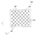
The surface sheet for absorbent articles shown in FIG. 4 was produced. As shown in FIG. 4, a large polygon region row BTL in which a plurality of large polygon regions BT are arranged adjacent to each other along the X direction, and a plurality of small polygon regions STL are adjacent to each other along the X direction. Are arranged alternately in the Y direction. The embossed
〔比較例1〕
図14に示す表面シート100Aを作製した。図14に示すように、エンボス部200の形状は、その中心点からの長さが等しい4本の棒状体からなるX字形状のみであり、熱収縮繊維層1d上に非熱収縮繊維層1uを重ね合わせた積層体の上層側から図14に示すパターンでエンボス接着し、4個のエンボス部200で囲まれた4角形状の凸部300となる部分のみを形成した。積層体のエンボス接着後、110℃±10℃の熱風を5〜10秒間通過させて、下層の熱収縮性繊維を捲縮させ、下層を収縮させると共に上層を凸状に突出させ、多数の立体ドーム構造の凸部300のみを有する表面シート100Aを作製した。エンボス部200は7.1個/cm2配されており、熱収縮後の表面シート100Aの最短距離にある隣り合う2つのエンボス部200の間隔は1.6mmであり、エンボス部200の面積は3.2mm2であった。また、4本の棒状体の長さは、同じ1.2mmであった。また、Y方向における棒状体同士の交差角度θは90°であった。
[Comparative Example 1]
A
〔比較例2〕
図15に示す表面シート100Bを作製した。図15に示すように、エンボス部200の形状は円形状のみであり、熱収縮繊維層1d上に非熱収縮繊維層1uを重ね合わせた積層体の上層側から図15に示すパターンでエンボス接着し、8個のエンボス部200で囲まれた8角形状の大凸部320となる部分と、4個のエンボス部200で囲まれた4角形状の小凸部330となる部分を形成した。尚、複数の8角形状の領域はX方向に沿って互いに隣接して配されているが、複数の4角形状の領域は、X方向に沿って互いに隣接して配されておらず、X方向に間隔を空けて配されている。積層体のエンボス接着後、110℃±10℃の熱風を5〜10秒間通過させて、下層の熱収縮性繊維を捲縮させ、下層を収縮させると共に上層を凸状に突出させ、多数の立体ドーム構造の大凸部320及び小凸部330を有する表面シート100Bを作製した。エンボス部200は5.5個/cm2配されており、熱収縮後の表面シート100Aの最短距離にある隣り合う2つのエンボス部200の間隔は1.1mmであり、エンボス部200の面積は3.1mm2であった。
[Comparative Example 2]
A
〔参考例1〕
図16に示す表面シート100Sを作製した。図16に示すように、エンボス部200の形状は、その中心点からの長さが長い2本の棒状体200a,200bと短い1本の棒状体200cとからなるY字形状のみであり、熱収縮繊維層1d上に非熱収縮繊維層1uを重ね合わせた積層体の上層側から図16に示すパターンでエンボス接着した。積層体のエンボス接着後、110℃±10℃の熱風を5〜10秒間通過させて、下層の熱収縮性繊維を捲縮させ、下層を収縮させると共に上層を凸状に突出させ、多数の立体ドーム構造の高凸部320、中凸部310及び低凸部330を有する表面シート100Sを作製した。エンボス部200は6個/cm2配されており、熱収縮後の表面シート100Sの第1方向(X方向)にある隣り合う2つのエンボス部200の最も近接する間隔は1.1mmであり、エンボス部200の面積は3.9mm2であった。また、2本の棒状体200a,200bの長さは2.8mmで、1本の棒状体200cの長さは0.85mmであった。また、高凸部320の高さhbは2.3mm、中凸部310の高さhaは1.3mm、低凸部330の高さhcは0.8mmであった。また、棒状体200aと棒状体200bとの交差角度θは110°、棒状体200aと棒状体200cとの交差角度θは125°、棒状体200bと棒状体200cとの交差角度θは125°であった。
[Reference Example 1]
A
〔性能評価〕
実施例1、比較例1〜2及び参考例1の各表面シートについて、下記方法に従って(1)肌との接触面積率、(2)表面液戻り性、(3)液流れ性、(4)肌との摩擦係数、(5)肌触り性、及び(6)低凸部の面積に対する高凸部の面積の割合(高凸部の面積/低凸部の面積)を評価した。評価環境は室温20℃、湿度60%RHであった。それらの結果を下記表1に示す。
[Performance evaluation]
About each surface sheet of Example 1, Comparative Examples 1-2 and Reference Example 1, according to the following method, (1) contact area ratio with skin, (2) surface liquid returnability, (3) liquid flowability, (4) The coefficient of friction with the skin, (5) feel, and (6) the ratio of the area of the high protrusion to the area of the low protrusion (area of the high protrusion / area of the low protrusion) were evaluated. The evaluation environment was a room temperature of 20 ° C. and a humidity of 60% RH. The results are shown in Table 1 below.
(1)肌との接触面積率
〔測定方法〕
実施例1、比較例1〜2及び参考例1の各表面シートについて、肌との接触面積を以下の方法で測定した。
各表面シートから60mm(CD方向)×80mm(MD方向)の大きさのカットサンプルを切り出す。無加圧の状態で、該カットサンプルの上部に透明の重さ50gのアクリル板を置き、更にアクリル板上に250gの錘を設置し、6.25gf/cm2の荷重を掛けた状態で、各カットサンプルの表面形状をKeyence社製、高精度形状計測システムKS−1100を用い測定し、画像を取り込んだ。取り込んだ画像をKeyence社製、形状解析アプリケーションKS−Analyzerを用い解析し、無荷重の状態から6.25gf/cm2の荷重を掛けた状態で厚み方向に変化した部分を抽出し、二値化処理することにより、装着時に肌と接触する部分の画像を得た。この画像をプリンターで印刷し、コンピューターに取り込んだ。画像の取り込みには、カットサンプルの中央部を使用し、光源として[サンライトSL−230K2;LPL(株)社製]を2台使用し、CDカメラ(HV−37;日立電子(株)社製)とレンズ(Nikon製 Ai AF Nikol 24mmF2.8D)をFマウントにより接続し、Nexus製NewQube(Ver.4.22)を用いて画像の取り込み・処理を行い、接触面積を測定した。その後、測定した接触面積を、カットサンプル全体の面積で除することで、「接触面積率」を算出した。前記測定で得られた接触面積率を、肌との接触面積率と定義する。
(1) Contact area ratio with skin [Measurement method]
About each surface sheet of Example 1, Comparative Examples 1-2, and Reference Example 1, the contact area with skin was measured with the following method.
A cut sample having a size of 60 mm (CD direction) × 80 mm (MD direction) is cut out from each surface sheet. In an unpressurized state, a transparent acrylic plate having a weight of 50 g is placed on top of the cut sample, a 250 g weight is further placed on the acrylic plate, and a load of 6.25 gf / cm 2 is applied. The surface shape of each cut sample was measured using a high-precision shape measurement system KS-1100 manufactured by Keyence, and an image was captured. Analyzing the captured image using Keyence's shape analysis application KS-Analyzer, extracting the portion that has changed in the thickness direction under a load of 6.25 gf / cm 2 from the unloaded state, and binarized By processing, an image of a portion in contact with the skin at the time of wearing was obtained. This image was printed with a printer and loaded into a computer. To capture the image, the center of the cut sample is used, and two [Sunlight SL-230K2; manufactured by LPL Co., Ltd.] are used as light sources, and a CD camera (HV-37; Hitachi Electronics Co., Ltd.). The lens (Nikon Ai AF Nicol 24mmF2.8D) was connected by an F mount, and an image was captured and processed using Nexus NewQube (Ver. 4.22), and the contact area was measured. Thereafter, the “contact area ratio” was calculated by dividing the measured contact area by the area of the entire cut sample. The contact area ratio obtained by the measurement is defined as the contact area ratio with the skin.
(2)表面液戻り性
〔測定方法〕
実施例1、比較例1〜2及び参考例1の各表面シートを60mm(CD方向)×80mm(MD方向)の大きさに切り出し、それぞれを同形同大の吸収シート(パルプ200g/m2および吸収性ポリマー50g/m2)上にホットメルト接着剤を介して接着して測定サンプルを作製した。次に、測定サンプルを表面シートが表面側となるようにして水平に置き、底部に直径1cmの注入口が付いた円筒つきアクリル板を重ねて、注入口から脱繊維馬血(日本バイオテスト(株)製)を9g注入し、注入後1分間その状態を保持した。次に、円筒つきアクリル板を取り除き、表面シートの表面上に、縦6cm×横9.5cmで坪量13g/m2の吸収紙(市販のティッシュペーパー)を16枚重ねて載せた。更にその上に圧力が4.0×102Paになるように重りを載せて5秒間加圧した。加圧後、吸収紙を取り出し、加圧前後の紙の重さを測定して、紙に吸収された脱繊維馬血の重量を測定して表面液戻り量とした。
(2) Surface liquid return [Measurement method]
Each surface sheet of Example 1, Comparative Examples 1 and 2 and Reference Example 1 was cut into a size of 60 mm (CD direction) × 80 mm (MD direction), and each was the same shape and size absorbent sheet (pulp 200 g / m 2). Further, a measurement sample was prepared by adhering to a absorbent polymer (50 g / m 2 ) via a hot melt adhesive. Next, place the measurement sample horizontally so that the surface sheet is on the surface side, and stack an acrylic plate with a cylinder with a 1 cm diameter injection port on the bottom, and remove fibrotic horse blood from the injection port (Nippon Biotest ( 9 g) was injected, and the state was maintained for 1 minute after the injection. Next, the acrylic plate with a cylinder was removed, and 16 sheets of absorbent paper (commercially available tissue paper) having a length of 6 cm × width of 9.5 cm and a basis weight of 13 g / m 2 were placed on the surface of the surface sheet. Further, a weight was placed thereon so that the pressure was 4.0 × 10 2 Pa, and pressure was applied for 5 seconds. After pressurization, the absorbent paper was taken out, the weight of the paper before and after pressurization was measured, and the weight of defibrinated horse blood absorbed by the paper was measured to obtain the surface liquid return amount.
(3)液流れ性
〔測定方法〕
実施例1、比較例1〜2及び参考例1の各表面シートを150mm(MD方向)×50mm(CD方向)の大きさに切り出し、それぞれを同形同大の吸収シート(パルプ200g/m2および吸収性ポリマー50g/m2)上にホットメルト接着剤を介して接着して測定サンプルを作製した。試験装置は、測定サンプルの載置面が45°傾斜している載置部を有している。この載置部に、表面シートが上方を向くように測定サンプルを載置した。次いで、試験液として、着色させた蒸留水を1g/10secの速度で測定サンプルに滴下させた。そして、初めに表面シートが濡れた地点から試験液が吸収シートに初めて吸収された地点までの距離を測定した。以上の操作を3回行い、3回の平均値を液流れ距離(mm)として求めた。液流れ距離は、液が装着者の肌をどの程度伝うのかの指標となるものであり、液流れ距離が短いほど高評価となる。評価は以下の基準で採点した。
A:液流れ距離の平均値が15mm未満
B:液流れ距離の平均値が15mm以上50mm未満
C:液流れ距離の平均値が50mm以上100mm未満
尚、液流れ距離の平均値が100mmを超えたものに関しては、>100と表記する。
(3) Liquid flow [Measurement method]
Each surface sheet of Example 1, Comparative Examples 1 and 2 and Reference Example 1 was cut into a size of 150 mm (MD direction) × 50 mm (CD direction), and each was the same shape and size absorbent sheet (pulp 200 g / m 2 Further, a measurement sample was prepared by adhering to a absorbent polymer (50 g / m 2 ) via a hot melt adhesive. The test apparatus has a mounting portion in which the mounting surface of the measurement sample is inclined by 45 °. A measurement sample was placed on the placement portion so that the topsheet faced upward. Next, colored distilled water was dropped as a test solution onto the measurement sample at a rate of 1 g / 10 sec. Then, the distance from the point where the top sheet was first wetted to the point where the test liquid was first absorbed by the absorbent sheet was measured. The above operation was performed three times, and the average value of the three times was determined as the liquid flow distance (mm). The liquid flow distance is an index of how much the liquid propagates through the wearer's skin, and the shorter the liquid flow distance, the higher the evaluation. Evaluation was scored according to the following criteria.
A: The average value of the liquid flow distance is less than 15 mm B: The average value of the liquid flow distance is 15 mm or more and less than 50 mm C: The average value of the liquid flow distance is 50 mm or more and less than 100 mm Note that the average value of the liquid flow distance exceeds 100 mm For things, it is expressed as> 100.
(4)肌との摩擦係数
〔測定方法〕
実施例1、比較例1〜2及び参考例1の各表面シートについて、肌との摩擦係数を以下の方法で測定した。
実施例1、比較例1〜2及び参考例1の各表面シートを50mm(MD方向)×50mm(CD方向)の大きさに切り出し、フックのついた錘(重量211g、縦63mm×横63mm×厚み7mm)に紙製両面テープを用い、サンプルの凸部と反対側の面が裏面となるように接着した。錘を接着したサンプルの凸部側の面が下側になるようアクリル版の上に静置し、フックにワイヤーを取り付け、滑車を介してオリエンテック社製の引張試験機Tensilon RTC−1210Aに取り付けた。引張速度200mm/分で、サンプルに接着した錘を引っ張り、アクリル板上を水平方向に滑らせた。記録されたチャートの荷重の平均値を摩擦力とし、錘を接着したサンプルの重量から、摩擦係数を算出した。前記測定で得られた摩擦係数を、肌との摩擦係数と定義する。
(4) Coefficient of friction with skin [Measurement method]
About each surface sheet of Example 1, Comparative Examples 1-2, and Reference Example 1, the friction coefficient with skin was measured with the following method.
Each surface sheet of Example 1, Comparative Examples 1-2 and Reference Example 1 was cut into a size of 50 mm (MD direction) × 50 mm (CD direction), and a weight with a hook (weight 211 g, length 63 mm × width 63 mm × A paper double-sided tape was used for the thickness 7 mm), and adhesion was performed so that the surface opposite to the convex portion of the sample was the back surface. Place the sample on the acrylic plate so that the convex side of the sample with the weight attached is on the bottom, attach the wire to the hook, and attach it to the tensile tester Tensilon RTC-1210A manufactured by Orientec via a pulley. It was. The weight adhered to the sample was pulled at a pulling speed of 200 mm / min and slid horizontally on the acrylic plate. The average value of the load of the recorded chart was made into friction force, and the friction coefficient was computed from the weight of the sample which adhered the weight. The coefficient of friction obtained by the measurement is defined as the coefficient of friction with the skin.
(5)肌触り性
〔測定方法〕
実施例1、比較例1〜2及び参考例1の各表面シートを、水平な台の上に凸部側の面が上になるように置いた。肌触り性を専門パネラー10名により評価した。評価基準は、ざらつきが明確に無い場合を3点、ざらつきがややある場合を2点、ざらつきがある場合を1点として採点し、平均値を算出した。評価は以下の基準で採点した。
A:平均値が2.5以上3以下
B:平均値が2.0以上2.5未満
C:平均値が1.0以上2.0未満
(5) Touchability [Measurement method]
Each surface sheet of Example 1, Comparative Examples 1 and 2 and Reference Example 1 was placed on a horizontal table so that the surface on the convex side was up. The touch was evaluated by 10 expert panelists. The evaluation criteria were scored with 3 points when there was no roughness, 2 points when there was some roughness, and 1 point when there was roughness, and the average value was calculated. Evaluation was scored according to the following criteria.
A: Average value is 2.5 or more and 3 or less B: Average value is 2.0 or more and less than 2.5 C: Average value is 1.0 or more and less than 2.0
(6)低凸部の面積に対する高凸部の面積の割合
〔測定方法〕
実施例1の表面シートに関しては、低凸部を含む小多角形領域を形成する4個のエンボス部それぞれの重心を結ぶ直線によって囲まれた面積を、低凸部の面積として求めた。また、高凸部を含む大多角形領域を形成する6個のエンボス部それぞれの重心を結ぶ直線によって囲まれた面積を、高凸部の面積として求めた。次に、比較例1の表面シート100Aに関しては、図14に示すように、高凸部及び低凸部の2種類の凸部が無く、1種類の凸部300しかないため、該凸部300を含む4角形状の領域を形成する4個のエンボス部200それぞれの重心を結ぶ直線によって囲まれた面積を、低凸部の面積及び高凸部の面積として求めた。次に、比較例2の表面シート100Bに関しては、図15に示すように、小凸部330を含む4角形領域を形成する4個のエンボス部200それぞれの重心を結ぶ直線によって囲まれた面積を、低凸部の面積として求めた。また、大凸部320を含む8角形領域を形成する8個のエンボス部200それぞれの重心を結ぶ直線によって囲まれた面積を、高凸部の面積として求めた。次に、参考例1の表面シート100Sに関しては、図16に示すように、高凸部320、中凸部310及び低凸部330を備えており、低凸部330を含む4角形領域を形成する、Y方向に隣り合う棒状体200aの先端と棒状体200bの先端とを結ぶ直線及びX方向に隣り合う棒状体200aの先端と棒状体200bの先端とを結ぶ直線によって囲まれた面積を、低凸部の面積として求めた。また、高凸部320を含む8角形領域を形成する4個のY字状のエンボス部200によって囲まれた面積、具体的には、Y字状のエンボス部200の輪郭、Y方向に隣り合う棒状体200cの先端どうしを結ぶ直線及びX方向に隣り合う棒状体200aの先端と棒状体200bの先端とを結ぶ直線によって囲まれた面積を、高凸部の面積として求めた。
(6) Ratio of the area of the high convex part to the area of the low convex part [Measuring method]
Regarding the surface sheet of Example 1, the area surrounded by straight lines connecting the centroids of the four embossed portions forming the small polygonal region including the low convex portion was determined as the area of the low convex portion. Moreover, the area surrounded by the straight line connecting the centers of gravity of each of the six embossed portions forming the large polygonal region including the high convex portion was determined as the area of the high convex portion. Next, regarding the

表1の結果によれば、実施例1の表面シートは、肌との接触面積率が最も低く、比較例1の表面シートに比べて1/3程度にまで低くなっている。従って、実施例1の表面シートを吸収性物品に用いると、べたつき感やムレをさらに低減し、肌へのダメージを減らす効果が期待できる。しかも、実施例1の表面シートは、肌との摩擦係数が最も低く、肌へのダメージを抑える効果が期待できる。
また、実施例1の表面シートは、表面液戻り性が最も低くなっている。従って、実施例1の表面シートを、例えば吸収性物品に用いると、表面液戻り性が低いので、べたつき感やムレをさらに低減し、肌へのダメージを減らすことができる。しかも、実施例1の表面シートは、液流れ性も良好なので、実施例1の表面シートを吸収性物品に用いると、体液が表面から下側へと移行し易く、装着中の液漏れの危険性を低減できるとともに、体液が表面に残ることによる肌ダメージを抑制することが期待である。
また、実施例1の表面シートは、肌との摩擦係数が最も低く、しかも肌触り性も良好なので、実施例1の表面シートを吸収性物品に用いると、風合いが柔らかく、使用感が向上することが期待できる。
更に、実施例1の表面シートは、参考例1の表面シートと比較すると、エンボス化率を低くしたにも関わらす、低凸部の面積に対する高凸部の面積の割合を小さくすることができ、しかも肌との接触面積率を減らすことができている。したがって、風合いが柔らかく、かつ、エンボス部分での液溜まりを抑制することが容易となる。
According to the results in Table 1, the surface sheet of Example 1 has the lowest contact area ratio with the skin, and is about 1/3 lower than the surface sheet of Comparative Example 1. Therefore, when the surface sheet of Example 1 is used for an absorbent article, an effect of further reducing stickiness and stuffiness and reducing damage to the skin can be expected. Moreover, the surface sheet of Example 1 has the lowest coefficient of friction with the skin, and an effect of suppressing damage to the skin can be expected.
Moreover, the surface sheet of Example 1 has the lowest surface liquid returnability. Therefore, when the surface sheet of Example 1 is used for an absorbent article, for example, the surface liquid returnability is low, so that stickiness and stuffiness can be further reduced and damage to the skin can be reduced. In addition, since the surface sheet of Example 1 has good liquid flow properties, when the surface sheet of Example 1 is used for absorbent articles, body fluid easily moves from the surface to the lower side, and there is a risk of liquid leakage during wearing. It is expected to reduce skin damage caused by body fluid remaining on the surface.
Moreover, since the surface sheet of Example 1 has the lowest coefficient of friction with the skin and also has good touch properties, when the surface sheet of Example 1 is used for an absorbent article, the texture is soft and the feeling of use is improved. Can be expected.
Furthermore, compared with the surface sheet of Example 1, the surface sheet of Example 1 can reduce the ratio of the area of the high protrusions to the area of the low protrusions even though the embossing rate is lowered. Moreover, the contact area ratio with the skin can be reduced. Therefore, the texture is soft and it is easy to suppress liquid accumulation at the embossed portion.
1A,1B、1C 表面シート
2 エンボス部
21 中間エンボス部
21a 2方向延出形状部
21e 突出部
22 他エンボス部
22e 突出部
BT 大多角形領域
ST 小多角形領域
3 凸部
31 高凸部
32 低凸部
10 生理用ナプキン(吸収性物品)
11 吸収性本体
12 裏面シート
13 吸収体
14 サイドシート
15 ウイング部
16 固定部
1A, 1B,
DESCRIPTION OF
Claims (8)
複数の前記エンボス部によって囲まれた大多角形領域を複数有し、該エンボス部は該大多角形領域の頂部をなしており、
複数の前記大多角形領域の頂部をなす前記エンボス部によって囲まれた、該大多角形領域よりも面積が小さい小多角形領域を複数有し、該エンボス部は該小多角形領域の頂部もなしており、
各前記大多角形領域内には高凸部が形成され、各前記小多角形領域内には、該高凸部よりも高さの低い低凸部が形成されており、
複数の前記大多角形領域が第1方向に沿って互いに隣接して配されて構成された大多角形領域列と、複数の前記小多角形領域が該第1方向に沿って互いに隣接して配されて構成された小多角形領域列とが、該第1方向と直交する第2方向に交互に配されており、
前記高凸部が前記第1方向に沿って複数配して構成された高凸部列と、前記低凸部が該第1方向に沿って複数配して構成された低凸部列とが、該第1方向と直交する第2方向に交互に配されており、
前記エンボス部は、前記第2方向に関して最も近い位置にある2つの前記高凸部どうしの間で、且つ、前記第1方向に関して最も近い位置にある2つの前記低凸部どうしの間に中間エンボス部を有しており、
前記第2方向に関して最も近い位置にある2つの前記大多角形領域は、1つの頂部を共有しており、
前記中間エンボス部は、該頂部の中心点から一方の前記大多角形領域の外形を形成している辺に沿って延びると共に、該頂部の中心点から他方の前記大多角形領域の外形を形成している辺に沿って延びる4方向延出形状に形成されている吸収性物品用の表面シート。 A surface sheet for an absorbent article having a heat-shrinkable fiber layer including heat-shrinkable heat-shrinkable fibers and having a plurality of embossed portions formed thereon,
A plurality of large polygonal regions surrounded by a plurality of the embossed portions, the embossed portions forming the tops of the large polygonal regions;
A plurality of small polygon regions having a smaller area than the large polygon region, surrounded by the embossed portions forming the tops of the plurality of large polygon regions, and the embossed portion also forms the top of the small polygon region. And
High convex portions are formed in each of the large polygon regions, and low convex portions having a height lower than that of the high convex portions are formed in each of the small polygon regions,
A plurality of large polygon regions are arranged adjacent to each other along the first direction, and a plurality of small polygon regions are arranged adjacent to each other along the first direction. Are arranged alternately in a second direction orthogonal to the first direction ,
A high convex portion row configured by arranging a plurality of the high convex portions along the first direction, and a low convex portion row configured by arranging a plurality of the low convex portions along the first direction. , Alternately arranged in a second direction orthogonal to the first direction,
The embossed portion is an intermediate embossed portion between the two high convex portions located closest to each other in the second direction and between the two low convex portions located closest to each other in the first direction. Have
The two large polygonal regions that are closest to each other in the second direction share one apex;
The intermediate embossed portion extends from the center point of the top portion along a side forming the outer shape of one of the large polygonal regions, and forms the outer shape of the other large polygonal region from the central point of the top portion. A top sheet for absorbent articles, which is formed in a four-direction extending shape extending along the side .
The absorbent article has a longitudinal direction corresponding to the longitudinal direction of the wearer and a lateral direction perpendicular thereto, and the large polygon region row and the small polygon region row are arranged along the lateral direction. The absorbent article according to claim 7 .
Priority Applications (5)
| Application Number | Priority Date | Filing Date | Title |
|---|---|---|---|
| JP2014065073A JP6310294B2 (en) | 2014-03-27 | 2014-03-27 | Top sheet for absorbent articles |
| CN201580011498.4A CN106061452B (en) | 2014-03-27 | 2015-03-17 | The positive dough sheet of absorbent commodity and absorbent commodity with the positive dough sheet |
| PCT/JP2015/057894 WO2015146717A1 (en) | 2014-03-27 | 2015-03-17 | Surface sheet for absorbent article and absorbent article including surface sheet |
| RU2016141089A RU2666826C2 (en) | 2014-03-27 | 2015-03-17 | Surface sheet for absorbent article and absorbent article including surface sheet |
| TW104109429A TWI695714B (en) | 2014-03-27 | 2015-03-24 | Front sheet for absorbent articles and absorbent article provided with the front sheet |
Applications Claiming Priority (1)
| Application Number | Priority Date | Filing Date | Title |
|---|---|---|---|
| JP2014065073A JP6310294B2 (en) | 2014-03-27 | 2014-03-27 | Top sheet for absorbent articles |
Related Child Applications (1)
| Application Number | Title | Priority Date | Filing Date |
|---|---|---|---|
| JP2018048563A Division JP6492204B2 (en) | 2018-03-15 | 2018-03-15 | Top sheet for absorbent articles |
Publications (3)
| Publication Number | Publication Date |
|---|---|
| JP2015186543A JP2015186543A (en) | 2015-10-29 |
| JP2015186543A5 JP2015186543A5 (en) | 2017-02-02 |
| JP6310294B2 true JP6310294B2 (en) | 2018-04-11 |
Family
ID=54195240
Family Applications (1)
| Application Number | Title | Priority Date | Filing Date |
|---|---|---|---|
| JP2014065073A Active JP6310294B2 (en) | 2014-03-27 | 2014-03-27 | Top sheet for absorbent articles |
Country Status (5)
| Country | Link |
|---|---|
| JP (1) | JP6310294B2 (en) |
| CN (1) | CN106061452B (en) |
| RU (1) | RU2666826C2 (en) |
| TW (1) | TWI695714B (en) |
| WO (1) | WO2015146717A1 (en) |
Families Citing this family (26)
| Publication number | Priority date | Publication date | Assignee | Title |
|---|---|---|---|---|
| JP6375971B2 (en) * | 2015-01-28 | 2018-08-22 | 王子ホールディングス株式会社 | Absorbent article top sheet |
| JP6098592B2 (en) * | 2014-09-02 | 2017-03-22 | 王子ホールディングス株式会社 | Absorbent article top sheet |
| JP6399305B2 (en) * | 2015-01-28 | 2018-10-03 | 王子ホールディングス株式会社 | Absorbent article top sheet |
| JP6447176B2 (en) * | 2015-01-28 | 2019-01-09 | 王子ホールディングス株式会社 | Absorbent article top sheet |
| NZ728936A (en) * | 2014-09-02 | 2018-02-23 | Oji Holdings Corp | Top sheet for absorbent article |
| JP6361519B2 (en) * | 2015-01-28 | 2018-07-25 | 王子ホールディングス株式会社 | Absorbent article top sheet |
| JP6632343B2 (en) * | 2015-11-12 | 2020-01-22 | 花王株式会社 | Absorbent articles |
| JP2017086621A (en) * | 2015-11-12 | 2017-05-25 | 花王株式会社 | Absorbent product |
| JP2017086619A (en) * | 2015-11-12 | 2017-05-25 | 花王株式会社 | Absorbent product |
| JP2017086706A (en) * | 2015-11-13 | 2017-05-25 | 王子ホールディングス株式会社 | Top sheet of absorbent article |
| WO2017094409A1 (en) * | 2015-12-01 | 2017-06-08 | 花王株式会社 | Absorbent article |
| JP6220032B2 (en) * | 2015-12-01 | 2017-10-25 | 花王株式会社 | Absorbent articles |
| JP6395700B2 (en) * | 2015-12-28 | 2018-09-26 | ユニ・チャーム株式会社 | Nonwoven fabric for absorbent articles and method for producing the nonwoven fabric |
| JP6744121B2 (en) * | 2016-04-14 | 2020-08-19 | 花王株式会社 | Non-woven |
| ITUA20163073A1 (en) * | 2016-05-02 | 2017-11-02 | Pantex Int S P A | MULTILAYERED MATERIAL INCLUDING AT LEAST ONE NON-WOVEN FABRIC LAYER |
| KR20190003652A (en) | 2016-05-02 | 2019-01-09 | 트레데가르 필름 프로덕츠 코포레이션 | Apparatus for producing molded films and molded films |
| JP6860302B2 (en) * | 2016-07-14 | 2021-04-14 | 花王株式会社 | Absorbent article |
| JP6271657B1 (en) * | 2016-08-09 | 2018-01-31 | 花王株式会社 | Top sheet for absorbent articles |
| JP6788496B2 (en) * | 2016-12-27 | 2020-11-25 | 花王株式会社 | Absorbent article |
| JP6764781B2 (en) * | 2016-12-27 | 2020-10-07 | 花王株式会社 | Absorbent article |
| JP6941490B2 (en) * | 2016-12-27 | 2021-09-29 | 花王株式会社 | Absorbent article |
| JP6539768B2 (en) | 2017-06-16 | 2019-07-03 | 花王株式会社 | Absorbent articles |
| JP6553137B2 (en) * | 2017-08-30 | 2019-07-31 | 大王製紙株式会社 | Absorbent articles |
| JP7057102B2 (en) | 2017-11-22 | 2022-04-19 | 花王株式会社 | Absorbent article |
| JP6706646B2 (en) * | 2018-05-29 | 2020-06-10 | 花王株式会社 | Absorbent article |
| GB2596718A (en) * | 2019-03-18 | 2022-01-05 | Procter & Gamble | Shaped nonwovens that exhibit high visual resolution |
Family Cites Families (11)
| Publication number | Priority date | Publication date | Assignee | Title |
|---|---|---|---|---|
| MY128983A (en) * | 1995-03-03 | 2007-03-30 | Kao Corp | Surface sheet for absorbent article |
| SG67494A1 (en) * | 1997-04-08 | 1999-09-21 | Uni Charm Corp | Disposable absorbent article having liquid-passages on top surface thereof |
| JP3732339B2 (en) * | 1998-07-15 | 2006-01-05 | ユニ・チャーム株式会社 | Sanitary napkin |
| DE60131716T2 (en) * | 2000-09-22 | 2008-11-06 | Kao Corp. | Upper layer for absorbent article |
| JP4343992B2 (en) * | 2007-05-23 | 2009-10-14 | 花王株式会社 | Absorbent article surface sheet |
| JP5199646B2 (en) * | 2007-11-16 | 2013-05-15 | ユニ・チャーム株式会社 | Absorbent articles |
| JP2010148730A (en) * | 2008-12-25 | 2010-07-08 | Kao Corp | Surface sheet of absorbent article |
| JP5268662B2 (en) * | 2009-01-09 | 2013-08-21 | 花王株式会社 | Absorbent article surface sheet |
| JP5421676B2 (en) * | 2009-07-07 | 2014-02-19 | 花王株式会社 | Top sheet for absorbent articles |
| JP5792997B2 (en) * | 2011-05-20 | 2015-10-14 | 花王株式会社 | Absorbent articles |
| JP6108447B2 (en) * | 2013-03-27 | 2017-04-05 | 大王製紙株式会社 | Absorbent articles |
-
2014
- 2014-03-27 JP JP2014065073A patent/JP6310294B2/en active Active
-
2015
- 2015-03-17 WO PCT/JP2015/057894 patent/WO2015146717A1/en active Application Filing
- 2015-03-17 CN CN201580011498.4A patent/CN106061452B/en active Active
- 2015-03-17 RU RU2016141089A patent/RU2666826C2/en active
- 2015-03-24 TW TW104109429A patent/TWI695714B/en active
Also Published As
| Publication number | Publication date |
|---|---|
| TW201540274A (en) | 2015-11-01 |
| RU2016141089A3 (en) | 2018-07-10 |
| WO2015146717A1 (en) | 2015-10-01 |
| JP2015186543A (en) | 2015-10-29 |
| CN106061452B (en) | 2019-08-16 |
| CN106061452A (en) | 2016-10-26 |
| RU2666826C2 (en) | 2018-09-12 |
| RU2016141089A (en) | 2018-04-27 |
| TWI695714B (en) | 2020-06-11 |
Similar Documents
| Publication | Publication Date | Title |
|---|---|---|
| JP6310294B2 (en) | Top sheet for absorbent articles | |
| JP5875157B2 (en) | Fiber sheet | |
| JP4343992B2 (en) | Absorbent article surface sheet | |
| JP5421676B2 (en) | Top sheet for absorbent articles | |
| JP6006068B2 (en) | Fiber sheet | |
| JP6044413B2 (en) | Absorbent article topsheet and absorbent article using the same | |
| JP6273101B2 (en) | Non-woven | |
| JP3877682B2 (en) | Top sheet for absorbent articles | |
| JP5211035B2 (en) | Three-dimensional shaped nonwoven fabric | |
| JP2011067484A (en) | Absorbent article | |
| JP2010148730A (en) | Surface sheet of absorbent article | |
| JP2007296001A (en) | Absorbent article | |
| JP6172808B2 (en) | Absorbent article surface sheet | |
| JP2017086621A (en) | Absorbent product | |
| JP6492204B2 (en) | Top sheet for absorbent articles | |
| JP2015112339A (en) | Top sheet of absorbent article and absorbent article | |
| JP6632343B2 (en) | Absorbent articles | |
| JP6940933B2 (en) | Absorbent article | |
| JP3210463U (en) | Nonwoven fabric, surface sheet of absorbent article using the same, and absorbent article using the same | |
| JP2012090689A (en) | Absorbent article | |
| KR101459016B1 (en) | Topsheet for absorbent article | |
| JP2015112340A (en) | Top sheet of absorbent article and absorbent article | |
| JP2016120006A (en) | Absorbent article | |
| JP6580420B2 (en) | Absorbent articles | |
| JP2017086619A (en) | Absorbent product |
Legal Events
| Date | Code | Title | Description |
|---|---|---|---|
| RD03 | Notification of appointment of power of attorney |
Free format text: JAPANESE INTERMEDIATE CODE: A7423 Effective date: 20160203 |
|
| A521 | Request for written amendment filed |
Free format text: JAPANESE INTERMEDIATE CODE: A523 Effective date: 20161212 |
|
| A621 | Written request for application examination |
Free format text: JAPANESE INTERMEDIATE CODE: A621 Effective date: 20161212 |
|
| A131 | Notification of reasons for refusal |
Free format text: JAPANESE INTERMEDIATE CODE: A131 Effective date: 20171107 |
|
| A521 | Request for written amendment filed |
Free format text: JAPANESE INTERMEDIATE CODE: A523 Effective date: 20171219 |
|
| RD04 | Notification of resignation of power of attorney |
Free format text: JAPANESE INTERMEDIATE CODE: A7424 Effective date: 20171219 |
|
| TRDD | Decision of grant or rejection written | ||
| A01 | Written decision to grant a patent or to grant a registration (utility model) |
Free format text: JAPANESE INTERMEDIATE CODE: A01 Effective date: 20180227 |
|
| A61 | First payment of annual fees (during grant procedure) |
Free format text: JAPANESE INTERMEDIATE CODE: A61 Effective date: 20180316 |
|
| R151 | Written notification of patent or utility model registration |
Ref document number: 6310294 Country of ref document: JP Free format text: JAPANESE INTERMEDIATE CODE: R151 |
|
| R250 | Receipt of annual fees |
Free format text: JAPANESE INTERMEDIATE CODE: R250 |
|
| R250 | Receipt of annual fees |
Free format text: JAPANESE INTERMEDIATE CODE: R250 |
|
| R250 | Receipt of annual fees |
Free format text: JAPANESE INTERMEDIATE CODE: R250 |
|
| R250 | Receipt of annual fees |
Free format text: JAPANESE INTERMEDIATE CODE: R250 |