JP6860302B2 - Absorbent article - Google Patents

Absorbent article Download PDF

Info

Publication number
JP6860302B2
JP6860302B2 JP2016139471A JP2016139471A JP6860302B2 JP 6860302 B2 JP6860302 B2 JP 6860302B2 JP 2016139471 A JP2016139471 A JP 2016139471A JP 2016139471 A JP2016139471 A JP 2016139471A JP 6860302 B2 JP6860302 B2 JP 6860302B2
Authority
JP
Japan
Prior art keywords
absorbent article
convex portion
surface sheet
longitudinal direction
fiber layer
Prior art date
Legal status (The legal status is an assumption and is not a legal conclusion. Google has not performed a legal analysis and makes no representation as to the accuracy of the status listed.)
Active
Application number
JP2016139471A
Other languages
Japanese (ja)
Other versions
JP2018007886A (en
Inventor
糸井 奈美江
奈美江 糸井
学 松井
学 松井
Current Assignee (The listed assignees may be inaccurate. Google has not performed a legal analysis and makes no representation or warranty as to the accuracy of the list.)
Kao Corp
Original Assignee
Kao Corp
Priority date (The priority date is an assumption and is not a legal conclusion. Google has not performed a legal analysis and makes no representation as to the accuracy of the date listed.)
Filing date
Publication date
Application filed by Kao Corp filed Critical Kao Corp
Priority to JP2016139471A priority Critical patent/JP6860302B2/en
Publication of JP2018007886A publication Critical patent/JP2018007886A/en
Application granted granted Critical
Publication of JP6860302B2 publication Critical patent/JP6860302B2/en
Active legal-status Critical Current
Anticipated expiration legal-status Critical

Links

Images

Description

本発明は、吸収性物品に関する。 The present invention relates to an absorbent article.

パンティライナー、生理用ナプキン等の吸収性物品の表面シートとして、一方向に延びる複数本の畝部と隣り合う各畝部間に位置する溝部とを有する、いわゆる畝溝構造を有する表面シートが知られており(特許文献1参照)、その畝部として高さの異なる複数の畝部を畝部が延びる方向と交互する方向に交互に設けることも提案されている(特許文献2参照)。 As a surface sheet for absorbent articles such as panty liners and sanitary napkins, a surface sheet having a so-called ridge groove structure, which has a plurality of ridges extending in one direction and a groove located between adjacent ridges, is known. (See Patent Document 1), and it has been proposed that a plurality of ridges having different heights are alternately provided as the ridges in a direction in which the ridges extend and in a direction alternating with the direction in which the ridges extend (see Patent Document 2).

これとは別に、本出願人は、先に、複数のエンボス部によって囲まれた大多角形領域及び小多角形領域を有し、該エンボス部が該大多角形領域及び該小多角形領域の頂部をなしている吸収性物品用の表面シートであって、各該大多角形領域内に高凸部が配され、各該小多角形領域内に低凸部が配されている表面シートを提案している(特許文献3参照)。 Apart from this, the Applicant previously has a large polygonal region and a small polygonal region surrounded by a plurality of embossed portions, and the embossed portion previously covers the large polygonal region and the top of the small polygonal region. We propose a surface sheet for an absorbent article that has a high convex portion arranged in each of the large polygonal regions and a low convex portion arranged in each of the small polygonal regions. (See Patent Document 3).

特開2008−025080号公報Japanese Unexamined Patent Publication No. 2008-0258080 特開2011−080178号公報Japanese Unexamined Patent Publication No. 2011-080178 特開2015−186543号公報Japanese Unexamined Patent Publication No. 2015-186543

特許文献1又は2に記載の表面シートによれば、畝部及び溝部に沿う方向に比べて畝部及び溝部と交差する方向には液が流れにくいため、畝部及び溝部が延びる方向を、着用者の前後方向に対応する方向に一致させて使用することによって、液が吸収性物品の側方から漏れ出す横漏れ等を防止することができる。
しかし、畝部及び溝部が延びる方向を、吸収性物品の長手方向に一致させて使用すると、吸収性物品が極めて薄かったり柔らかかったりする場合には、表面シートの溝部の位置で折れ曲がり易く、特に高さの異なる畝部を有する場合に顕著になる。そのため、着用中に吸収性物品にヨレが生じ易くなり、ヨレに起因する漏れが生じ易くなる。
特許文献3に記載の表面シートは、肌当接面に大小の凸部を有することによって、肌触りや液戻り防止性が良好であるが、その表面シートを用いて吸収性物品のヨレを防止する技術については何ら記載されていない。
According to the surface sheet described in Patent Document 1 or 2, since it is difficult for the liquid to flow in the direction intersecting the ridge and the groove as compared with the direction along the ridge and the groove, the direction in which the ridge and the groove extend is worn. By using the product in the direction corresponding to the front-back direction of the person, it is possible to prevent lateral leakage or the like in which the liquid leaks from the side of the absorbent article.
However, when the direction in which the ridges and grooves extend is aligned with the longitudinal direction of the absorbent article, when the absorbent article is extremely thin or soft, it is easily bent at the position of the groove in the surface sheet, and is particularly high. It becomes remarkable when it has different ridges. Therefore, the absorbent article is likely to be twisted during wearing, and leakage due to the twist is likely to occur.
The surface sheet described in Patent Document 3 has large and small convex portions on the skin contact surface, so that it has good touch and liquid return prevention property, but the surface sheet is used to prevent twisting of the absorbent article. No mention is made of the technology.

したがって本発明は、前述した従来技術が有する欠点を解消し得る吸収性物品を提供することにある。 Therefore, the present invention is to provide an absorbent article capable of eliminating the above-mentioned drawbacks of the prior art.

本発明は、肌当接面側に配された表面シート、非肌当接面側に配された裏面シート及びこれら両シート間に配された吸収体を備え、着用時に着用者の前後方向に一致する長手方向及び該長手方向に直交する幅方向を有している吸収性物品であって、前記表面シートは、肌当接面側に、吸収性物品の長手方向に沿って連続的又は非連続的に突出した高凸部を有する第1凸部と吸収性物品の長手方向に沿って連続的又は非連続的に突出した低凸部を有する第2凸部とを吸収性物品の幅方向に交互に有しており、前記低凸部は、前記高凸部よりも高さが低く且つ前記高凸部よりも繊維密度が高くなっており、前記表面シートと前記吸収体との間が、吸収性物品の幅方向に延在し吸収性物品の長手方向に間欠的に配された複数の接着部で接合されている、吸収性物品を提供するものである。 The present invention includes a front surface sheet arranged on the skin contact surface side, a back surface sheet arranged on the non-skin contact surface side, and an absorber arranged between these two sheets, and is provided in the front-rear direction of the wearer when worn. An absorbent article having a matching longitudinal direction and a width direction orthogonal to the longitudinal direction, wherein the surface sheet is continuous or non-continuous along the longitudinal direction of the absorbent article on the skin contact surface side. A first convex portion having a continuously protruding high convex portion and a second convex portion having a continuously or discontinuously protruding low convex portion along the longitudinal direction of the absorbent article are formed in the width direction of the absorbent article. The low-convex portion has a lower height than the high-convex portion and a higher fiber density than the high-convex portion, and the space between the surface sheet and the absorber is high. The present invention provides an absorbent article extending in the width direction of the absorbent article and joined by a plurality of adhesive portions intermittently arranged in the longitudinal direction of the absorbent article.

本発明の吸収性物品によれば、吸収性物品の幅方向に液が流れにくい上にヨレ難く、漏れ防止性に優れている。 According to the absorbent article of the present invention, the liquid does not easily flow in the width direction of the absorbent article, is not easily twisted, and has excellent leakage prevention properties.

図1(a)は、本発明の吸収性物品の一実施形態であるパンティライナーの平面図であり、図1(b)は、図1(a)から表面シートを取り除いた状態を示す分解平面図である。FIG. 1 (a) is a plan view of a panty liner according to an embodiment of the absorbent article of the present invention, and FIG. 1 (b) is a disassembled plan showing a state in which the surface sheet is removed from FIG. 1 (a). It is a figure. 図2は、図1のII−II線断面を模式的に示す断面図である。FIG. 2 is a cross-sectional view schematically showing a cross section taken along line II-II of FIG. 図3は、図1に示すパンティライナーの表面シートの一部を拡大して示す斜視図である。FIG. 3 is an enlarged perspective view showing a part of the surface sheet of the panty liner shown in FIG. 図4は、図3に示す表面シートにおける融着接合部の形状及び配置パターンを示す平面図である。FIG. 4 is a plan view showing the shape and arrangement pattern of the fusion spliced portion in the surface sheet shown in FIG. 図5は、図4に示す表面シートの一部を拡大して示す拡大平面図である。FIG. 5 is an enlarged plan view showing a part of the surface sheet shown in FIG. 4 in an enlarged manner. 図6は、図5のVI−VI線断面を模式的に示す断面図である。FIG. 6 is a cross-sectional view schematically showing the VI-VI line cross section of FIG. 図7は、図5に示す高凸部における融着接合部の形状及び配置パターンを示す拡大平面図である。FIG. 7 is an enlarged plan view showing the shape and arrangement pattern of the fusion spliced portion in the highly convex portion shown in FIG. 図8は、図5に示す低凸部における融着接合部の形状及び配置パターンを示す拡大平面図である。FIG. 8 is an enlarged plan view showing the shape and arrangement pattern of the fusion spliced portion in the low convex portion shown in FIG. 図9は、図4に示すIX−IX線断面を模式的に示す断面図である。FIG. 9 is a cross-sectional view schematically showing the IX-IX line cross section shown in FIG. 図10は、図4に示すX−X線断面を模式的に示す断面図である。FIG. 10 is a cross-sectional view schematically showing the X-ray cross section shown in FIG. 図11は、図4に示すXI−XI線断面を模式的に示す断面図である。FIG. 11 is a cross-sectional view schematically showing the cross section of the XI-XI line shown in FIG. 図12は、本発明の吸収性物品の他の実施形態における接着部の配置を示す図1(b)相当図である。FIG. 12 is a view corresponding to FIG. 1 (b) showing the arrangement of the adhesive portion in another embodiment of the absorbent article of the present invention. 図13は、本発明の吸収性物品の更に他の実施形態における表面シートの融着接合部の形状及び配置パターンを示す平面図である。FIG. 13 is a plan view showing the shape and arrangement pattern of the fusion spliced portion of the surface sheet in still another embodiment of the absorbent article of the present invention. 図14は、本発明の吸収性物品の更に他の実施形態における表面シートの融着接合部の形状及び配置パターンを示す平面図である。FIG. 14 is a plan view showing the shape and arrangement pattern of the fusion spliced portion of the surface sheet in still another embodiment of the absorbent article of the present invention.

以下、本発明の吸収性物品について、その好ましい実施形態に基づき、図面を参照しながら説明する。
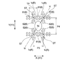
本発明の吸収性物品の一実施形態であるパンティライナー10(以下、パンティライナー10とも言う)は、図2に示すように、肌当接面側に配された表面シート1、非肌当接面側に配された裏面シート2及びこれら両シート1,2間に配された吸収体3を備え、図1(a)に示すように、着用時に着用者の前後方向に一致する長手方向X及び該長手方向Xに直交する幅方向Yを有している。吸収性物品の長手方向Xは、吸収性物品の平面視において、着用時に着用者の前側(腹側)に配される一端1fと着用者の後ろ側(背中側)に配される他端1rとを結ぶ方向及び該方向に平行な方向であり、吸収性物品の幅方向Yとは、吸収性物品の平面視において、吸収性物品の長手方向Xと直交する方向である。本発明の吸収性物品は、前後の区別のないもの、例えば前後対称の形状のものであっても良く、その場合、長手方向の両端のうちの任意に選択した一端を前側に配される一端、任意に選択した一端とは反対側の一端を後ろ側に配される他端とする。また、肌当接面とは、吸収性物品の表裏両面のうち、着用時に着用者の肌側に配される面であり、非肌当接面とは、吸収性物品の表裏両面のうち、着用時に着用者の肌側とは反対側に向けられる面である。
Hereinafter, the absorbent article of the present invention will be described based on its preferred embodiment with reference to the drawings.
As shown in FIG. 2, the panty liner 10 (hereinafter, also referred to as panty liner 10), which is an embodiment of the absorbent article of the present invention, has a surface sheet 1 arranged on the skin contact surface side and a non-skin contact. A back surface sheet 2 arranged on the front surface side and an absorber 3 arranged between the two sheets 1 and 2 are provided, and as shown in FIG. 1 (a), a longitudinal direction X that coincides with the front-back direction of the wearer when worn. And has a width direction Y orthogonal to the longitudinal direction X. In the plan view of the absorbent article, the longitudinal direction X of the absorbent article is one end 1f arranged on the front side (ventral side) of the wearer and the other end 1r arranged on the back side (back side) of the wearer when worn. The width direction Y of the absorbent article is a direction orthogonal to the longitudinal direction X of the absorbent article in the plan view of the absorbent article. The absorbent article of the present invention may have a front-rear indistinguishable shape, for example, a front-rear symmetrical shape, in which case an arbitrarily selected end of both ends in the longitudinal direction is arranged on the front side. , The one end opposite to the arbitrarily selected one end is the other end arranged on the rear side. The skin contact surface is a surface of the front and back surfaces of the absorbent article that is arranged on the wearer's skin side when worn, and the non-skin contact surface is a surface of the front and back surfaces of the absorbent article. This is the surface that faces the wearer's skin side when worn.

パンティライナー10について、より具体的に説明すると、パンティライナー10は、幅方向Yの中央部に、パンティライナー10と同方向に長い形状の吸収体3を備えている。吸収体3は、任意の平面視形状とすることができるが、パンティライナー10における吸収体3は、パンティライナー10の長手方向Xに沿って縦長の矩形状の平面視形状を有している。 More specifically, the panty liner 10 is provided with an absorber 3 having a shape long in the same direction as the panty liner 10 at the center of the width direction Y. The absorber 3 can have an arbitrary plan view shape, but the absorber 3 in the panty liner 10 has a vertically long rectangular plan view shape along the longitudinal direction X of the panty liner 10.

表面シート1及び裏面シート2それぞれは、図2に示すように、吸収体3の肌当接面側の全面及び非肌当接面側の全面を覆っており、吸収体3の周縁から延出する延出部分を有している。表面シート1と裏面シート2は、吸収体3の周縁から延出する延出部分どうしが、パンティライナー10の周縁に沿って、接着、融着等により互いに接合されており、それによって、パンティライナー10の外周部に周縁シール部14が形成されている。パンティライナー10の裏面シート2の横方向Yの中央部の非肌対向面上には、粘着剤が塗布されて、パンティライナー10をショーツ等の下着に固定するための固定部5が形成されている。パンティライナー10は、長手方向Xに延びる中央線CLに対して線対称の形状を有している。 As shown in FIG. 2, each of the front surface sheet 1 and the back surface sheet 2 covers the entire surface of the absorber 3 on the skin contact surface side and the entire surface of the non-skin contact surface side, and extends from the peripheral edge of the absorber 3. Has an extended part. In the front surface sheet 1 and the back surface sheet 2, the extending portions extending from the peripheral edge of the absorber 3 are joined to each other along the peripheral edge of the panty liner 10 by adhesion, fusion, or the like, whereby the panty liner is joined. A peripheral seal portion 14 is formed on the outer peripheral portion of the 10. An adhesive is applied on the non-skin facing surface of the back sheet 2 of the panty liner 10 in the lateral direction Y, and a fixing portion 5 for fixing the panty liner 10 to underwear such as shorts is formed. There is. The panty liner 10 has a shape that is line-symmetrical with respect to the center line CL extending in the longitudinal direction X.

上述したパンティライナー10を構成する裏面シート2及び吸収体3としては、それぞれ、当該技術分野において従来用いられてきたものと同様のものを特に制限なく用いることができる。例えば、裏面シート2としては、合成樹脂製の液不透過性フィルムや、スパンボンド−メルトブローン−スパンボンド積層不織布等の耐水圧が高い撥水性の不織布を用いることができる。吸収体3としては、吸収性シートや、パルプ繊維等の吸収性繊維の集合体又はこれに吸水性ポリマーを保持させた吸収コアがティッシュペーパー等のコアラップシートによって被覆されているものを用いることができる。吸収性シートは、パルプ繊維等のセルロース系繊維からなる単層又は多層の繊維シートや、これに吸水性ポリマーを挟持又は担持させたもの等を用いることができる。表面シート1、裏面シート2及び吸収体3の固定には、通常、パンティライナーや生理用ナプキン等の吸収性物品に用いられる接着剤やヒートエンボス、超音波エンボス、高周波エンボス等の融着手段が用いられる。 As the back sheet 2 and the absorber 3 constituting the panty liner 10 described above, the same ones conventionally used in the art can be used without particular limitation. For example, as the back sheet 2, a liquid-impermeable film made of synthetic resin or a water-repellent non-woven fabric having high water pressure resistance such as spunbond-melt blown-spunbond laminated non-woven fabric can be used. As the absorbent body 3, an absorbent sheet, an aggregate of absorbent fibers such as pulp fibers, or an absorbent core in which a water-absorbent polymer is held therein is coated with a core wrap sheet such as tissue paper. Can be done. As the absorbent sheet, a single-layer or multi-layer fiber sheet made of cellulosic fibers such as pulp fibers, or a sheet having a water-absorbent polymer sandwiched or supported therein can be used. Adhesives usually used for absorbent articles such as panty liners and sanitary napkins, and fusion means such as heat embossing, ultrasonic embossing, and high frequency embossing are used to fix the front surface sheet 1, the back surface sheet 2, and the absorber 3. Used.

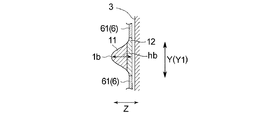
パンティライナー10における表面シート1は、図1(a)及び図3に示すように、肌当接面側に、パンティライナー10の長手方向Xに沿って非連続的に突出した複数の高凸部1bを有する高凸部列1bL(第1凸部)とパンティライナー10の長手方向Xに沿って非連続的に突出した複数の低凸部1sからなる低凸部列1sL(第2凸部)とを、パンティライナー10の幅方向Yに交互に有している。また、低凸部列1sLを構成する個々の低凸部1sは、図3に示すように、高凸部1bよりも高さが低い。また低凸部列1sLを構成する個々の低凸部1sは、高凸部列1bLを構成する個々の高凸部1bよりも繊維密度が高くなっている。 高凸部1b及び低凸部1sの高さは、それぞれ、表面シートの厚み方向Zの頂点における高さhb(図9参照)及びhs(図11参照)である。また、高凸部1bと低凸部1sの繊維密度の高低は、それぞれの頂部1bu、1suにおける繊維密度の比較により決定する。なお、繊維密度の比率の計測方法については、後に詳細に述べる。 As shown in FIGS. 1A and 3, the surface sheet 1 of the panty liner 10 has a plurality of highly convex portions that project discontinuously along the longitudinal direction X of the panty liner 10 toward the skin contact surface side. Low convex portion row 1sL (second convex portion) composed of a high convex portion row 1bL having 1b (first convex portion) and a plurality of low convex portions 1s protruding discontinuously along the longitudinal direction X of the panty liner 10. And are alternately held in the width direction Y of the panty liner 10. Further, as shown in FIG. 3, the height of each low-convex portion 1s constituting the low-convex portion row 1sL is lower than that of the high-convex portion 1b. Further, the individual low-convex portions 1s constituting the low-convex portion row 1sL have a higher fiber density than the individual high-convex portions 1b constituting the high-convex portion row 1bL. The heights of the high convex portion 1b and the low convex portion 1s are the heights hb (see FIG. 9) and hs (see FIG. 11) at the apex of the surface sheet in the thickness direction Z, respectively. Further, the high and low fiber densities of the high convex portion 1b and the low convex portion 1s are determined by comparing the fiber densities at the tops 1bu and 1su, respectively. The method for measuring the fiber density ratio will be described in detail later.

表面シート1は、エアスルー不織布以外の不織布とすることもできるが、エアスルー不織布が好ましい。
「エアスルー不織布」とは、50℃以上の流体、例えば気体や水蒸気を、ウエブ又は不織布に吹き付ける工程を経て製造された不織布を言い、本工程のみで製造される不織布のみならず、他の方法で作製された不織布に本工程を付加して製造した不織布あるいは本工程の後に何らかの工程を行って製造した不織布をも含む意味である。エアスルー不織布は、単層のエアスルー不織布のみならず、多層のエアスルー不織布でも良く、更にエアスルー不織布と、他の不織布等の繊維シートやフィルム材とを複合化したものであっても良い。
The surface sheet 1 may be a non-woven fabric other than the air-through non-woven fabric, but the air-through non-woven fabric is preferable.
The "air-through non-woven fabric" refers to a non-woven fabric produced through a process of spraying a fluid of 50 ° C. or higher, for example, gas or water vapor onto a web or non-woven fabric, and is not limited to the non-woven fabric produced only in this step, but can be obtained by other methods. It means that the non-woven fabric produced by adding this step to the produced non-woven fabric or the non-woven fabric manufactured by performing some step after this step is also included. The air-through non-woven fabric may be not only a single-layer air-through non-woven fabric but also a multi-layer air-through non-woven fabric, and may be a composite of an air-through non-woven fabric and a fiber sheet or film material such as another non-woven fabric.

積層不織布である表面シート1において、図3に示すように、第1繊維層11と第2繊維層12とは隣接して直接に接しており、両層11,12間に他の層は介在していない。第1繊維層11と第2繊維層12とは、それらの層を構成する繊維の材料の種類、繊維の太さ、親水化処理の有無、層の形成方法等の要因によって区別される。表面シート1の厚み方向Zに沿う断面を光学顕微鏡(株式会社キーエンス製、VHX−1000 デジタルマイクロスコープ)で拡大すると、これらの要因に起因して、両層11,12の境界部分を観察することができる。パンティライナー10では、表面シート1は、第1繊維層11を肌対向面側に配し、第2繊維層12を非肌対向面側に配して使用されている。 In the surface sheet 1 which is a laminated non-woven fabric, as shown in FIG. 3, the first fiber layer 11 and the second fiber layer 12 are adjacent and directly in contact with each other, and other layers are interposed between the two layers 11 and 12. Not done. The first fiber layer 11 and the second fiber layer 12 are distinguished by factors such as the type of fiber material constituting the layers, the thickness of the fibers, the presence or absence of hydrophilic treatment, and the method of forming the layers. When the cross section of the surface sheet 1 along the thickness direction Z is enlarged with an optical microscope (VHX-1000 digital microscope manufactured by KEYENCE CORPORATION), the boundary portion between the two layers 11 and 12 can be observed due to these factors. Can be done. In the panty liner 10, the surface sheet 1 is used by arranging the first fiber layer 11 on the skin-facing surface side and the second fiber layer 12 on the non-skin-facing surface side.

表面シート1では、図3に示すように、第1繊維層11は、第2繊維層12側から第1繊維層11側に向けて突出した複数の高凸部1bと、高凸部1bよりも高さの低い複数の低凸部1sとを有している。好適には、表面シート1は、図4及び図5に示すように、複数の高凸部1bと、複数の低凸部1sと、高凸部1b及び低凸部1sに亘って連続して延びる連結凸部1cとを有している。連結凸部1cは、第1繊維層11が、第2繊維層12側から第1繊維層11側に向けて低凸部1sよりも低く隆起して形成されている。言い換えれば、高凸部1b及び低凸部1sは、その内部が第1繊維層11を構成する繊維で満たされている。そして、連結凸部1cも、内部が第1繊維層11を構成する繊維で満たされている。 In the surface sheet 1, as shown in FIG. 3, the first fiber layer 11 is formed from a plurality of highly convex portions 1b protruding from the second fiber layer 12 side toward the first fiber layer 11 side and the highly convex portions 1b. Also has a plurality of low convex portions 1s having a low height. Preferably, as shown in FIGS. 4 and 5, the surface sheet 1 is continuously extended over a plurality of high-convex portions 1b, a plurality of low-convex portions 1s, and a high-convex portion 1b and a low-convex portion 1s. It has an extending connecting convex portion 1c. The connecting convex portion 1c is formed by the first fiber layer 11 protruding from the second fiber layer 12 side toward the first fiber layer 11 side lower than the low convex portion 1s. In other words, the inside of the high convex portion 1b and the low convex portion 1s is filled with the fibers constituting the first fiber layer 11. The inside of the connecting convex portion 1c is also filled with the fibers constituting the first fiber layer 11.

表面シート1では、第1繊維層11及び第2繊維層12は、いずれもランダムに堆積された繊維から構成された繊維層であり、それ以上に細分化された複数層の積層体から構成されたものではない。 In the surface sheet 1, the first fiber layer 11 and the second fiber layer 12 are both fiber layers composed of randomly deposited fibers, and are composed of a laminate of a plurality of layers further subdivided. It's not a thing.

表面シート1では、第2繊維層12は、熱収縮した熱収縮性繊維を含む熱収縮繊維層である。一方、表面シート1では、第1繊維層11は、第2繊維層12に積層されており、非熱収縮性繊維を含む非熱収縮繊維層である。表面シート1は、第1繊維層11と第2繊維層12とが融着接合された融着接合部6を複数備えている。好適には、表面シート1は、図3,図4に示すように、第1繊維層11と第2繊維層12とが、規則的に配された複数の融着接合部6により部分的に接合されて貼り合わされており、非肌対向面側の第2繊維層12の熱収縮性繊維を熱収縮して形成されている。表面シート1には、第1繊維層11の肌対向面側からエンボス加工を施した融着接合部6により凹陥した複数の凹部と、エンボス加工を施していない非エンボス加工部分に複数の凸部とが形成されている。融着接合部6により凹部となった部分の繊維密度は、融着接合されていない凸部の部分よりも高くなっており、表面シート1の中で最も高くなっている。
融着接合部6は、例えば熱エンボス、超音波エンボスなどの各種融着手段によって形成される。
In the surface sheet 1, the second fiber layer 12 is a heat-shrinkable fiber layer containing heat-shrinkable heat-shrinkable fibers. On the other hand, in the surface sheet 1, the first fiber layer 11 is laminated on the second fiber layer 12, and is a non-heat-shrinkable fiber layer containing non-heat-shrinkable fibers. The surface sheet 1 includes a plurality of fusion-bonded portions 6 in which the first fiber layer 11 and the second fiber layer 12 are fusion-bonded. Preferably, as shown in FIGS. 3 and 4, the surface sheet 1 is partially formed by a plurality of fused joints 6 in which the first fiber layer 11 and the second fiber layer 12 are regularly arranged. It is joined and bonded, and is formed by heat-shrinking the heat-shrinkable fibers of the second fiber layer 12 on the non-skin facing surface side. The surface sheet 1 has a plurality of concave portions recessed by the fusion-bonded portion 6 embossed from the skin-facing surface side of the first fiber layer 11, and a plurality of convex portions on the non-embossed portion that has not been embossed. And are formed. The fiber density of the concave portion formed by the fusion-bonded portion 6 is higher than that of the convex portion not joined by fusion bonding, and is the highest in the surface sheet 1.
The fusion splicing portion 6 is formed by various fusion means such as thermal embossing and ultrasonic embossing.

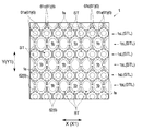
表面シート1は、複数の融着接合部6によって囲まれた大多角形領域BTを複数有し、融着接合部6は大多角形領域BTの頂部をなしている。また、表面シート1は、複数の大多角形領域BTの頂部をなす融着接合部6によって囲まれた、大多角形領域BTよりも面積が小さい小多角形領域STを複数有し、融着接合部6は小多角形領域STの頂部もなしている。このように、表面シート1は、複数の融着接合部6によって囲まれた多角形領域(大多角形領域BT,小多角形領域ST)が形成されており、該多角形領域(大多角形領域BT,小多角形領域ST)内が非エンボス加工部となっている。好適には、図4,図5に示すように、多角形領域は、複数の融着接合部6を頂部とし、これらによって囲まれた複数の相対的に面積の大きい大多角形領域BTと、隣接する複数の大多角形領域BTの頂部をなす融着接合部6を共通の頂部として囲まれた、大多角形領域BTよりも面積が小さい複数の小多角形領域STとを有している。このように、大多角形領域BTとこれに隣接する小多角形領域STとは、融着接合部6を共通の頂部としている。なお、本明細書において、「融着接合部6を頂部として」いる、或いは、「融着接合部6が頂点をなす」、とは、融着接合部6全体を頂点としている、という限定的な意味ではなく、融着接合部6の一部を頂点としている場合も含む意味である。本実施形態の表面シート1では、融着接合部6の一部が各多角形領域の頂点となっており、融着接合部6の頂点を除く残部が各多角形領域の外形をなす辺の一部となっている。また、「融着接合部6によって囲まれた」という表現は、融着接合部6の内側で構成される領域を意味するのではなく、融着接合部6を含んで構成される領域を意味する。 The surface sheet 1 has a plurality of large polygonal region BTs surrounded by a plurality of fusion joints 6, and the fusion joints 6 form the top of the large polygonal region BT. Further, the surface sheet 1 has a plurality of small polygonal regions ST having a smaller area than the large polygonal region BT and surrounded by fusion splicing portions 6 forming the tops of the plurality of large polygonal region BTs. 6 also forms the top of the small polygonal region ST. As described above, the surface sheet 1 is formed with a polygonal region (large polygonal region BT, small polygonal region ST) surrounded by a plurality of fusion splicing portions 6, and the polygonal region (large polygonal region BT) is formed. , Small polygon area ST) is a non-embossed part. Preferably, as shown in FIGS. 4 and 5, the polygonal region has a plurality of fusion splicing portions 6 at the top and is adjacent to a plurality of relatively large polygonal region BTs surrounded by these. It has a plurality of small polygonal regions ST having an area smaller than that of the large polygonal region BT, surrounded by a fusion joint 6 forming the tops of the plurality of large polygonal regions BT as a common top. As described above, the large polygonal region BT and the small polygonal region ST adjacent thereto have the fusion joint portion 6 as a common top. In addition, in this specification, "the fusion joint 6 is the apex" or "the fusion joint 6 is the apex" is limited to the fact that the entire fusion joint 6 is the apex. It does not mean that the meaning is, but also includes the case where a part of the fusion joint portion 6 is the apex. In the surface sheet 1 of the present embodiment, a part of the fusion splicing portion 6 is the apex of each polygonal region, and the rest excluding the apex of the fusion splicing portion 6 is a side forming the outer shape of each polygonal region. It is a part. Further, the expression "surrounded by the fusion joint 6" does not mean a region formed inside the fusion joint 6, but means a region including the fusion joint 6. To do.

詳述すると、表面シート1では、大多角形領域BTは、図4,図5に示すように、頂部をなす6個の融着接合部6によって囲まれており、外形が六角形状となっている。一方、小多角形領域STは、頂部をなす4個の融着接合部6によって囲まれており、外形が四角形状となっている。そして、パンティライナー10の長手方向Xに沿う第1方向X1に関しては、隣り合う2つの大多角形領域BT,BTどうしが、各大多角形領域BTを構成している6つの融着接合部6の内の2つの融着接合部6(2つの後述する他接合部62)を共有し、該2つの融着接合部6(2つの後述する他接合部62)を結ぶ辺によって互いに区分されている。また、パンティライナー10の幅方向Yに沿う第2方向Y1に関しては、隣り合う2つの大多角形領域BT,BTどうしが、各大多角形領域BTを構成する6つの融着接合部6の内の1つの融着接合部6(後述する中間接合部61)を共有し、該1つの融着接合部6(後述する中間接合部61)によって互いに区分されている。また、1個の四角形の小多角形領域STが、それぞれ、4個の六角形の大多角形領域BTによって囲まれている。隣り合う小多角形領域STと各大多角形領域BTとは、6つの融着接合部6の内の2つの融着接合部6(後述する中間接合部61及び後述する他接合部62)を共有し、該2つの融着接合部6(後述する中間接合部61及び後述する他接合部62)によって互いに区分されている。したがって、表面シート1においては、小多角形領域STを構成する4つの融着接合部6は、全て、該小多角形領域STに隣接する4個の大多角形領域BTを構成する融着接合部6と共有している。 More specifically, in the surface sheet 1, the large polygonal region BT is surrounded by six fusion joints 6 forming the top, as shown in FIGS. 4 and 5, and has a hexagonal outer shape. .. On the other hand, the small polygonal region ST is surrounded by four fusion splicing portions 6 forming the top, and has a quadrangular outer shape. Then, with respect to the first direction X1 along the longitudinal direction X of the panty liner 10, the two adjacent large polygonal regions BT and BT are among the six fusion joints 6 constituting each large polygonal region BT. The two fusion joints 6 (two other joints 62 described later) are shared, and the two fusion joints 6 (two other joints 62 described later) are separated from each other by the side connecting the two fusion joints 6 (two other joints 62 described later). Further, with respect to the second direction Y1 along the width direction Y of the panty liner 10, the two adjacent large polygonal regions BT and BT are one of the six fusion joints 6 constituting each large polygonal region BT. It shares one fusion joint 6 (intermediate joint 61 described later) and is separated from each other by the one fusion joint 6 (intermediate joint 61 described later). Further, one quadrangular small polygonal region ST is surrounded by four hexagonal large polygonal regions BT, respectively. Adjacent small polygon regions ST and each large polygon region BT share two fusion joints 6 (intermediate joint 61 described later and other joint 62 described later) among the six fusion joints 6. Then, they are separated from each other by the two fusion joints 6 (intermediate joint 61 described later and other joint 62 described later). Therefore, in the surface sheet 1, all the four fusion joints 6 constituting the small polygon region ST are the fusion joints forming the four large polygon regions BT adjacent to the small polygon region ST. It is shared with 6.

表面シート1では、図3,図4に示すように、複数の大多角形領域BTが、パンティライナー10の長手方向Xに沿う第1方向X1に沿って互いに隣接して配されて構成された大多角形領域列BTLが形成されている。また、表面シート1では、複数の小多角形領域STが、パンティライナー10の長手方向Xに沿う第1方向X1に沿って互いに隣接して配されて構成された小多角形領域列STLが形成されている。そして、大多角形領域列BTLと小多角形領域列STLとが、パンティライナー10の幅方向Yに沿う第2方向Y1に交互に配されている。即ち、パンティライナー10の幅方向Yに沿う第2方向Y1に沿って、大多角形領域列BTL,小多角形領域列STL,大多角形領域列BTL,・・・と交互に配置されている。 In the surface sheet 1, as shown in FIGS. 3 and 4, a plurality of large polygonal region BTs are arranged adjacent to each other along the first direction X1 along the longitudinal direction X of the panty liner 10. A square region row BTL is formed. Further, in the surface sheet 1, a small polygonal region row STL formed by arranging a plurality of small polygonal regions ST adjacent to each other along a first direction X1 along the longitudinal direction X of the panty liner 10 is formed. Has been done. The large polygonal region row BTL and the small polygonal region row STL are alternately arranged in the second direction Y1 along the width direction Y of the panty liner 10. That is, the large polygonal region row BTL, the small polygonal region row STL, the large polygonal region row BTL, ... Are arranged alternately along the second direction Y1 along the width direction Y of the panty liner 10.

表面シート1では、図5,図6に示すように、各大多角形領域BT内には相対的に高さの高い高凸部1bが形成されている。また、表面シート1においては、高凸部1bがパンティライナー10の長手方向Xに沿う第1方向X1に沿って複数配されて高凸部列1bLを構成している。一方、各小多角形領域ST内には、高凸部1bよりも高さの低い低凸部1sが形成されている。また、表面シート1においては、低凸部1sがパンティライナー10の長手方向Xに沿う第1方向X1に沿って複数配されて低凸部列1sLを構成している。そして、高凸部列1bLと低凸部列1sLとが、パンティライナー10の幅方向Yに沿う第2方向Y1に交互に配されている。即ち、パンティライナー10の幅方向Yに沿う第2方向Y1に沿って、高凸部列1bL,低凸部列1sL,高凸部列1bL,・・・と交互に配置されている。そして、高凸部列1bLの高凸部1bと低凸部列1sLの低凸部1sとは、表面シート1上で千鳥状に配置されている。言い換えると、高凸部1bと低凸部1sとは、長手方向Xに沿う第1方向X1と幅方向Yに沿う第2方向Y1のそれぞれに対して斜めの方向に向かって交互に並んでいる。 In the surface sheet 1, as shown in FIGS. 5 and 6, a relatively high convex portion 1b is formed in each large polygonal region BT. Further, in the surface sheet 1, a plurality of highly convex portions 1b are arranged along the first direction X1 along the longitudinal direction X of the panty liner 10 to form a highly convex portion row 1bL. On the other hand, in each small polygonal region ST, a low convex portion 1s having a height lower than that of the high convex portion 1b is formed. Further, in the surface sheet 1, a plurality of low convex portions 1s are arranged along the first direction X1 along the longitudinal direction X of the panty liner 10 to form a low convex portion row 1sL. The high convex portion row 1bL and the low convex portion row 1sL are alternately arranged in the second direction Y1 along the width direction Y of the panty liner 10. That is, the high convex portion row 1bL, the low convex portion row 1sL, the high convex portion row 1bL, ... Are alternately arranged along the second direction Y1 along the width direction Y of the panty liner 10. The high convex portion 1b of the high convex portion row 1bL and the low convex portion 1s of the low convex portion row 1sL are arranged in a staggered manner on the surface sheet 1. In other words, the high convex portion 1b and the low convex portion 1s are alternately arranged in diagonal directions with respect to each of the first direction X1 along the longitudinal direction X and the second direction Y1 along the width direction Y. ..

本実施形態のパンティライナー10によれば、表面シート1が、長手方向Xに沿って非連続的に突出した複数の高凸部を有する高凸部列1bL(第1凸部)と、長手方向Xに沿って非連続的に突出した複数の低凸部を有する低凸部列1sL(第2凸部)とを、幅方向Yに交互に有し、肌当接面に高さが異なる複数種類の第1及び第2凸部を有するため、パンティライナー10の使用中に、高凸部列1bL(第1凸部)は着用者の肌に接触する一方、低凸部列1sL(第2凸部)は着用者の肌に接触しない状況が生じ易い。そのため、高凸部列1bL(第1凸部)が肌に接触して、肌に付着した液が、高凸部列1bLの高凸部を伝って表面シート1内に取り込まれやすい上に、高凸部列1bL(第1凸部)と低凸部列1sL(第2凸部)との間に入り込んだ液が、繊維密度の高い低凸部列1sL(第2凸部)の低凸部1s付近から吸収体3へと引き込まれ易い一方、低凸部1sから肌に液が逆戻りしにくい。
また、低凸部列1sL(第2凸部)は着用者の肌に接触しない状況が生じ易いことによって、表面シート1と肌との接触面積が低減されるため、肌触りも良好である。
According to the panty liner 10 of the present embodiment, the surface sheet 1 has a high-convex portion row 1bL (first convex portion) having a plurality of high-convex portions protruding discontinuously along the longitudinal direction X, and a longitudinal direction. A plurality of low-convex portion rows 1sL (second convex portions) having a plurality of low-convex portions protruding discontinuously along X are alternately provided in the width direction Y and have different heights on the skin contact surface. Due to having the first and second convex parts of the type, during the use of the panty liner 10, the high convex part row 1bL (first convex part) comes into contact with the wearer's skin, while the low convex part row 1sL (second convex part). The convex part) tends to be in a situation where it does not come into contact with the wearer's skin. Therefore, the high-convex portion row 1bL (first convex portion) comes into contact with the skin, and the liquid adhering to the skin is easily taken into the surface sheet 1 along the high-convex portion of the high-convex portion row 1bL. The liquid that has entered between the high-convex row 1bL (first convex portion) and the low-convex row 1sL (second convex portion) is the low-convex low-convex row 1sL (second convex portion) having a high fiber density. While it is easy to be drawn into the absorber 3 from the vicinity of the portion 1s, it is difficult for the liquid to return to the skin from the low convex portion 1s.
Further, the low convex portion row 1sL (second convex portion) tends to be in a situation where it does not come into contact with the wearer's skin, so that the contact area between the surface sheet 1 and the skin is reduced, so that the touch is also good.

また、パンティライナー10においては、表面シート1と吸収体3との間が、パンティライナー10の幅方向Yに各々延在しパンティライナー10の長手方向Xに間欠的に配された複数の接着部4で接合されている。接着部4は、パンティライナー10の長手方向Xに等間隔に配されていることが好ましい。 Further, in the panty liner 10, a plurality of adhesive portions extending between the surface sheet 1 and the absorber 3 in the width direction Y of the panty liner 10 and intermittently arranged in the longitudinal direction X of the panty liner 10. It is joined at 4. The adhesive portions 4 are preferably arranged at equal intervals in the longitudinal direction X of the panty liner 10.

本実施形態のパンティライナー10によれば、高凸部列1bL(第1凸部)及び低凸部列1sL(第2凸部)が長手方向Xに延在していることによって、表面シート1上に排泄された液が、パンティライナー10の長手方向Xに比して幅方向Yに流れにくい上に、表面シート1と吸収体3との間が、幅方向Yに延在し長手方向Xに間欠的に配された複数の接着部4で接合されていることによって、第1凸部及び第2凸部を有する表面シート1が折れ曲がり易いことにより生じ易くなるパンティライナー10のヨレという弊害が生じにくく、吸収体3への吸収阻害も生じにくい。これにより、本実施形態のパンティライナー10によれば、幅方向Y及び前後のいずれの方向からも液が流れ出しにくくなり、優れた漏れ防止性が得られる。 According to the panty liner 10 of the present embodiment, the surface sheet 1 is formed by extending the high convex portion row 1bL (first convex portion) and the low convex portion row 1sL (second convex portion) in the longitudinal direction X. The liquid excreted above is less likely to flow in the width direction Y than in the longitudinal direction X of the panty liner 10, and the space between the surface sheet 1 and the absorber 3 extends in the width direction Y and is extended in the longitudinal direction X. Since the surface sheet 1 having the first convex portion and the second convex portion is easily bent due to being joined by a plurality of adhesive portions 4 intermittently arranged in the panty liner 10, there is an adverse effect of twisting of the panty liner 10. It is unlikely to occur, and absorption inhibition into the absorber 3 is also unlikely to occur. As a result, according to the panty liner 10 of the present embodiment, it becomes difficult for the liquid to flow out from any of the width direction Y and the front and rear directions, and excellent leakage prevention property can be obtained.

また、本実施形態のパンティライナー10によれば、第1凸部を構成する高凸部1b及び第2凸部を有する低凸部1sが、いずれも繊維層から構成されており、低凸部1sは、繊維層を構成する繊維によって内部が満たされているため、低凸部1sにおける剛性が向上し、低凸部1sを有する低凸部列1sLで屈曲することに起因する吸収性物品のヨレが生じ難い。また、低凸部1sに加えて高凸部1bも、繊維層を構成する繊維によって内部が満たされているため、ヨレ防止性能が一層向上する。 Further, according to the panty liner 10 of the present embodiment, the high convex portion 1b forming the first convex portion and the low convex portion 1s having the second convex portion are both composed of a fiber layer, and the low convex portion is formed. Since the inside of 1s is filled with the fibers constituting the fiber layer, the rigidity in the low convex portion 1s is improved, and the absorbent article is bent due to bending in the low convex portion row 1sL having the low convex portion 1s. It is hard to get twisted. Further, since the inside of the high convex portion 1b is filled with the fibers constituting the fiber layer in addition to the low convex portion 1s, the twist prevention performance is further improved.

また、本実施形態のパンティライナー10によれば、本発明の第1凸部及び第2凸部として、パンティライナー10の長手方向Xに沿って連続的に突出した高凸部又は低凸部を有するものではなく、複数の高凸部1bを有する高凸部列1bL及び複数の低凸部1sを有する低凸部列1sLを有するため、表面シート1と肌との接触面積が更に低減され、肌触りやムレ防止性、装着感が一層良好であるとともに、吸収性物品の肌の表面形状への追従変形性が向上し、ヨレ防止性能が一層向上する。
なお、本実施形態に用いた表面シート1における高凸部列1bLは、パンティライナー10の長手方向Xにおける高凸部1bの中心間距離P1(図4参照)が、パンティライナー10の幅方向Yにおける高凸部列1bLどうしの中心間距離P2(図4参照)よりも短い。また、本実施形態に用いた表面シート1における低凸部列1sLは、パンティライナー10の長手方向Xにおける低凸部1sの中心間距離P3(図5参照)が、パンティライナー10の幅方向Yにおける低凸部列1sLどうしの中心間距離P4(図5参照)よりも短い。これにより、表面シート1上に排泄された液は、一層、パンティライナー10の長手方向Xに比して幅方向Yに流れにくくなっている。
Further, according to the panty liner 10 of the present embodiment, as the first convex portion and the second convex portion of the present invention, a high convex portion or a low convex portion that continuously protrudes along the longitudinal direction X of the panty liner 10 is formed. Since it has a high-convex row 1bL having a plurality of high-convex portions 1b and a low-convex row 1sL having a plurality of low-convex portions 1s, the contact area between the surface sheet 1 and the skin is further reduced. The feel, stuffiness prevention, and wearing feeling are further improved, and the deformability of the absorbent article to follow the surface shape of the skin is improved, and the twist prevention performance is further improved.
In the highly convex portion row 1bL of the surface sheet 1 used in the present embodiment, the center-to-center distance P1 (see FIG. 4) of the highly convex portion 1b in the longitudinal direction X of the panty liner 10 is the width direction Y of the panty liner 10. It is shorter than the center-to-center distance P2 (see FIG. 4) between the highly convex row 1bL in the above. Further, in the low-convex portion row 1sL of the surface sheet 1 used in the present embodiment, the center-to-center distance P3 (see FIG. 5) of the low-convex portion 1s in the longitudinal direction X of the panty liner 10 is the width direction Y of the panty liner 10. It is shorter than the center-to-center distance P4 (see FIG. 5) between the low-convex rows 1 sL in the above. As a result, the liquid excreted on the surface sheet 1 is more difficult to flow in the width direction Y than in the longitudinal direction X of the panty liner 10.

上述した一又は二以上の効果がより確実に奏されるようにする観点から、個々の接着部4は、パンティライナー10の幅方向Yに沿う長さL1〔図1(b)参照〕が、パンティライナー10の長手方向Xに沿う幅W1〔図1(b)参照〕の、好ましくは5倍以上、より好ましくは7倍以上であり、また好ましくは30倍以下、より好ましくは20倍以下であり、また好ましくは5倍以上30倍以下、より好ましくは7倍以上20倍以下である。また同様の観点から、個々の接着部4は、パンティライナー10の幅方向Yに沿う長さL1〔図1(b)参照〕が、長手方向Xにおける、その接着部4が設けられた各位置における吸収体3の幅W3〔図1(b)参照〕の、好ましくは30%以上、より好ましくは50%以上であり、また好ましくは200%以下、より好ましくは150%以下であり、また好ましくは30%以上200%以下、より好ましくは50%以上150%以下である。接着部4は、図1(b)に示すように、表面シート1と吸収体3とを接合している部分に加えて、吸収体3の幅方向の外方に延出して、表面シート1とその下に位置する部材とを接合している部分を有していても良い。接着部4のパンティライナー10の幅方向Yに沿う長さL1には、表面シート1とその下に位置する部材とを接合する部分が吸収体3の幅を超えて延在する場合、その延在部分の長さも含めた長さとする。 From the viewpoint of ensuring that one or more of the above-mentioned effects are exhibited more reliably, the individual adhesive portions 4 have a length L1 [see FIG. 1 (b)] along the width direction Y of the panty liner 10. The width W1 along the longitudinal direction X of the panty liner 10 is preferably 5 times or more, more preferably 7 times or more, and preferably 30 times or less, more preferably 20 times or less. Yes, and more preferably 5 times or more and 30 times or less, and more preferably 7 times or more and 20 times or less. From the same viewpoint, the individual adhesive portions 4 have a length L1 [see FIG. 1 (b)] along the width direction Y of the panty liner 10 at each position in the longitudinal direction X where the adhesive portion 4 is provided. The width W3 of the absorber 3 in the above [see FIG. 1 (b)] is preferably 30% or more, more preferably 50% or more, preferably 200% or less, more preferably 150% or less, and more preferably. Is 30% or more and 200% or less, more preferably 50% or more and 150% or less. As shown in FIG. 1B, the adhesive portion 4 extends outward in the width direction of the absorber 3 in addition to the portion where the surface sheet 1 and the absorber 3 are joined, and the surface sheet 1 It may have a portion that joins the member and the member located below it. When the portion joining the surface sheet 1 and the member located below the surface sheet 1 extends beyond the width of the absorber 3, the length L1 of the adhesive portion 4 along the width direction Y of the panty liner 10 extends. The length shall include the length of the existing part.

接着部4は、表面シート1及び吸収体3の一方又は双方に塗布した後、両者を重ねて加圧することにより形成することができる。接着剤としては、吸収性物品の各部の接合に従来使用される各種公知の接着剤を特に制限なく用いることができ、例えば、ホットメルト型接着剤が好ましく用いられる。ホットメルト型接着剤としては、スチレン系、オレフィン系等が挙げられる。スチレン系ホットメルト接着剤としては、スチレン−ブタジエン−スチレン共重合体(SBS)、スチレン−イソプレン−スチレン共重合体(SIS)、SBSの水素添加物であるスチレン−エチレン−ブチレン−スチレン共重合体(SEBS)、及びこれらの2種以上をブレンドしたブレンド系ホットメルト型接着剤を使用することができる。タック力と凝集力のバランスが取り易く、表面シート1及び吸収体3とともに幅方向Yに延びる高剛性部分を形成して吸収性物品のヨレ防止性を高める観点から、接着剤としては、特にSISとSBSとのブレンド系ホットメルト型接着剤、又はSISとSEBSのブレンド系ホットメルト型接着剤を用いることが好ましい。
また同様の観点から、接着部4における接着剤の坪量は、好ましくは5g/m倍以上、より好ましくは7g/m以上であり、また好ましくは30g/m以下、より好ましくは20g/m以下であり、好ましくは5g/m以上30g/m以下、より好ましくは7g/m以上20g/m以下である。
The adhesive portion 4 can be formed by applying the adhesive portion 4 to one or both of the surface sheet 1 and the absorber 3 and then superimposing and pressurizing the two. As the adhesive, various known adhesives conventionally used for joining each part of the absorbent article can be used without particular limitation, and for example, a hot melt type adhesive is preferably used. Examples of the hot melt type adhesive include styrene type adhesives and olefin type adhesives. Examples of the styrene-based hot melt adhesive include styrene-butadiene-styrene copolymer (SBS), styrene-isoprene-styrene copolymer (SIS), and styrene-ethylene-butylene-styrene copolymer which is a hydrogenated product of SBS. (SEBS) and a blended hot melt type adhesive in which two or more of these are blended can be used. As an adhesive, SIS is particularly suitable as an adhesive from the viewpoint of easily balancing the tacking force and the cohesive force and forming a highly rigid portion extending in the width direction Y together with the surface sheet 1 and the absorber 3 to improve the anti-twisting property of the absorbent article. It is preferable to use a blend-type hot-melt adhesive of SIS and SBS, or a blend-type hot-melt adhesive of SIS and SEBS.
From the same viewpoint, the basis weight of the adhesive in the adhesive portion 4 is preferably 5 g / m 2 times or more, more preferably 7 g / m 2 or more, and preferably 30 g / m 2 or less, more preferably 20 g. It is / m 2 or less, preferably 5 g / m 2 or more and 30 g / m 2 or less, and more preferably 7 g / m 2 or more and 20 g / m 2 or less.

また、接着部4は、パンティライナー10の長手方向Xに沿う幅W1〔図1(b),図11参照)が、低凸部列1sLを構成する個々の低凸部1sのパンティライナー10の長手方向に沿う長さLs(図5,図11参照)よりも短いことが好ましい。接着部4の前記幅W1を、低凸部1sの前記長さLsより短くすることで、接着部4が低凸部1sの非肌当接面側の全体が覆われて吸収阻害が生じることを防止しつつ、表面シート1と吸収体3との密着性を向上させることができ、優れた吸収性能と優れたヨレ防止性とを両立させることができる。同様の観点から、接着部4の前記幅W1は、個々の低凸部1sの前記長さLsの、10%以上がより好ましく、更に好ましくは20%以上であり、また60%以下がより好ましく、更に好ましくは50%以下である。同様の観点から、接着部4の前記幅W1は、好ましくは1.0mm以上、より好ましくは1.5mm以上であり、また好ましくは5.0mm以下、より好ましくは4.0mm以下であり、また好ましくは1.0mm以上5.0mm以下、より好ましくは1.5mm以上4.0mm以下である。 Further, the adhesive portion 4 has a width W1 [see FIGS. 1 (b) and 11) along the longitudinal direction X of the panty liner 10 of the panty liner 10 of each low convex portion 1s forming the low convex portion row 1sL. It is preferably shorter than the length Ls along the longitudinal direction (see FIGS. 5 and 11). By making the width W1 of the adhesive portion 4 shorter than the length Ls of the low convex portion 1s, the adhesive portion 4 covers the entire non-skin contact surface side of the low convex portion 1s and absorption inhibition occurs. It is possible to improve the adhesion between the surface sheet 1 and the absorber 3 while preventing the above, and it is possible to achieve both excellent absorption performance and excellent anti-twisting property. From the same viewpoint, the width W1 of the adhesive portion 4 is more preferably 10% or more, still more preferably 20% or more, and more preferably 60% or less of the length Ls of each low convex portion 1s. , More preferably 50% or less. From the same viewpoint, the width W1 of the adhesive portion 4 is preferably 1.0 mm or more, more preferably 1.5 mm or more, preferably 5.0 mm or less, more preferably 4.0 mm or less, and also. It is preferably 1.0 mm or more and 5.0 mm or less, and more preferably 1.5 mm or more and 4.0 mm or less.

また接着部4は、パンティライナー10の長手方向Xにおける間隔L2〔図1(b)〕が、高凸部列1bLを構成する個々の高凸部1bのパンティライナー10の長手方向に沿う長さLb(図7,図10参照)よりも長いことが好ましい。接着部4の間隔L2を、高凸部1bの長さLbより長くすることで、吸収体3と接着されていない低凸部1sが存在することとなり、吸収体3との密着性が向上するのに加え、低凸部1sから吸収体3への吸収阻害が生じにくく、優れた吸収性能と優れたヨレ防止性とを両立させることができる。同様の観点から、接着部4の前記間隔L2は、高凸部1bの前記長さLbの、110%以上がより好ましく、更に好ましくは120%以上であり、また200%以下がより好ましく、更に好ましくは150%以下である。
同様の観点から、接着部4の前記間隔L2は、好ましくは3mm以上、より好ましくは4mm以上であり、また好ましくは10mm以下、より好ましくは8mm以下であり、また好ましくは3mm以上10mm以下、より好ましくは4mm以上8mm以下である。
また、接着部4が分布する範囲の全長L4は、パンティライナー10の吸収体3の長手方向Xの全長L3に対して、好ましくは50%以上、より好ましくは60%以上であり、また好ましくは100%以下、より好ましくは90%以下であり、また好ましくは50%以上100%以下、より好ましくは60%以上90%以下である。
Further, the adhesive portion 4 has a length such that the interval L2 [FIG. 1 (b)] in the longitudinal direction X of the panty liner 10 is along the longitudinal direction of the panty liner 10 of each of the highly convex portions 1b constituting the highly convex portion row 1bL. It is preferably longer than Lb (see FIGS. 7 and 10). By making the interval L2 of the adhesive portion 4 longer than the length Lb of the high convex portion 1b, the low convex portion 1s that is not adhered to the absorber 3 exists, and the adhesion to the absorber 3 is improved. In addition to this, absorption inhibition from the low convex portion 1s to the absorber 3 is unlikely to occur, and excellent absorption performance and excellent twist prevention property can be achieved at the same time. From the same viewpoint, the distance L2 of the adhesive portion 4 is more preferably 110% or more, further preferably 120% or more, still more preferably 200% or less, and further preferably 200% or less of the length Lb of the highly convex portion 1b. It is preferably 150% or less.
From the same viewpoint, the distance L2 of the adhesive portion 4 is preferably 3 mm or more, more preferably 4 mm or more, preferably 10 mm or less, more preferably 8 mm or less, and preferably 3 mm or more and 10 mm or less. It is preferably 4 mm or more and 8 mm or less.
Further, the total length L4 of the range in which the adhesive portion 4 is distributed is preferably 50% or more, more preferably 60% or more, and preferably 60% or more with respect to the total length L3 of the absorber 3 of the panty liner 10 in the longitudinal direction X. It is 100% or less, more preferably 90% or less, and preferably 50% or more and 100% or less, more preferably 60% or more and 90% or less.

パンティライナー10においては、図7に示すように、高凸部列1bLを構成する個々の高凸部1bは、パンティライナー10の幅方向Yに沿う長さLb’が、パンティライナー10の長手方向Xに沿う長さLbよりも長い。そのため、パンティライナー10(吸収性物品)の幅方向からの圧力に対する高凸部1bの剛性が向上し、ヨレ防止性能が一層向上する。同様の観点から、高凸部1bは、前記長さLb’が前記長さLbの、110%以上がより好ましく、更に好ましくは120%以上であり、また150%以下がより好ましく、更に好ましくは130%以下である。 In the panty liner 10, as shown in FIG. 7, each of the highly convex portions 1b constituting the high convex portion row 1bL has a length Lb'along the width direction Y of the panty liner 10 in the longitudinal direction of the panty liner 10. It is longer than the length Lb along X. Therefore, the rigidity of the highly convex portion 1b with respect to the pressure from the width direction of the panty liner 10 (absorbent article) is improved, and the twist prevention performance is further improved. From the same viewpoint, the length Lb'of the high convex portion 1b is more preferably 110% or more, more preferably 120% or more, still more preferably 150% or less, still more preferably 150% or more of the length Lb. It is 130% or less.

また本実施形態のパンティライナー10における表面シート1は、前述したように、肌当接面を形成する第1繊維層11とこれに積層された第2繊維層12とを有する多層構造を有し、第1繊維層11と該第2繊維層12とが融着接合された融着接合部6が複数、相互に離間した状態に形成されており、前述した高凸部1b及び低凸部1sにおいては、第1繊維層11が第2繊維層12とは反対方向に向けて突出している。本実施形態のパンティライナー10は、斯かる構成の表面シート1を有するため、表面シート1と肌との接触面積が一層確実に低減されて、肌触りやムレ防止性、装着感が良好であるとともに、液の幅方向Yへの移動が抑制され、また接着部4によりヨレ防止性能が向上するため、漏れ防止性能にも優れる。 Further, as described above, the surface sheet 1 in the panty liner 10 of the present embodiment has a multilayer structure having a first fiber layer 11 forming a skin contact surface and a second fiber layer 12 laminated thereto. , A plurality of fusion-bonded portions 6 in which the first fiber layer 11 and the second fiber layer 12 are fusion-bonded are formed in a state of being separated from each other, and the high-convex portion 1b and the low-convex portion 1s described above are formed. In, the first fiber layer 11 projects in the direction opposite to that of the second fiber layer 12. Since the panty liner 10 of the present embodiment has the surface sheet 1 having such a configuration, the contact area between the surface sheet 1 and the skin is more reliably reduced, and the skin feel, stuffiness prevention property, and wearing feeling are good. Since the movement of the liquid in the width direction Y is suppressed and the twist prevention performance is improved by the adhesive portion 4, the leakage prevention performance is also excellent.

表面シート1では、図4,図5に示すように、融着接合部6は、パンティライナー10の幅方向Yに沿う第2方向Y1に関して最も近い位置にある2つの高凸部1b,1bどうしの間で、且つ、パンティライナー10の長手方向Xに沿う第1方向X1に関して最も近い位置にある2つの低凸部1s,1sどうしの間に中間接合部61を有している。具体的には、第2方向Y1に関して、最も近い高凸部列1bL,1bLを構成する各高凸部のうち最も近い2つの高凸部1b,1bどうしの間で、且つ、第2方向Y1に関して最も近い高凸部列1bL,1bLの間に位置する低凸部列1sLを構成する第1方向X1に関して最も近い2つの低凸部1s,1sどうしの間に、1個の中間接合部61を有している。表面シート1においては、複数の融着接合部6は、2種類の形状の接合部からなり、1つ目が中間接合部61であり、2つ目が中間接合部61を除く残りの他接合部62である。なお、本明細書において、「1個の接合部」とは、外形的に1つと見做せるエンボス加工部の形状のことをいい、該エンボス加工部の形状が複数のドットや破線で構成されていても「1個の接合部」という。 In the surface sheet 1, as shown in FIGS. 4 and 5, the fusion spliced portion 6 has two highly convex portions 1b and 1b that are closest to each other with respect to the second direction Y1 along the width direction Y of the panty liner 10. An intermediate joint 61 is provided between the two low-convex portions 1s and 1s that are closest to each other with respect to the first direction X1 along the longitudinal direction X of the panty liner 10. Specifically, with respect to the second direction Y1, between the two closest high-convex portions 1b and 1b among the each high-convex portion forming the closest high-convex portion rows 1bL and 1bL, and in the second direction Y1. One intermediate joint 61 between the two closest low-convex portions 1s, 1s with respect to the first direction X1 constituting the low-convex row 1sL located between the closest high-convex rows 1bL, 1bL. have. In the surface sheet 1, the plurality of fusion joints 6 are composed of two types of joints, the first is an intermediate joint 61 and the second is the remaining other joints excluding the intermediate joint 61. Part 62. In addition, in this specification, "one joint part" means the shape of the embossed part which can be regarded as one externally, and the shape of the embossed part is composed of a plurality of dots and broken lines. Even if it is, it is called "one joint".

表面シート1では、図4,図5に示すように、各中間接合部61は、第1方向X1に隣り合う四角形の小多角形領域ST,STにて、各小多角形領域STを構成する4つの融着接合部6の内の1つの融着接合部6として共有され、第2方向Y1に隣り合う六角形の大多角形領域BT,BTにて、各多角形領域BTを構成する6つの融着接合部6の内の1つの融着接合部6として共有されている。従って、各中間接合部61は、第1方向X1に関して最も近い2つの低凸部1s,1sどうしの中間位置に配されており、第2方向Y1に関して最も近い2つの高凸部1b,1bどうしの中間位置に配されている。 In the surface sheet 1, as shown in FIGS. 4 and 5, each intermediate joint portion 61 constitutes each small polygonal region ST by quadrangular small polygonal regions ST and ST adjacent to the first direction X1. Six hexagonal large polygonal regions BT and BT shared as one of the four fusional joints 6 and adjacent to the second direction Y1 to form each polygonal region BT. It is shared as one of the fusional joints 6 as one of the fusional joints 6. Therefore, each intermediate joint 61 is arranged at an intermediate position between the two low convex portions 1s and 1s closest to each other with respect to the first direction X1, and the two high convex portions 1b and 1b closest to each other with respect to the second direction Y1. It is arranged in the middle position of.

表面シート1では、図7に示すように、各中間接合部61は、第2方向Y1に関して最も近い位置にある2つの大多角形領域BTの頂点をなしている頂部の中心点から各大多角形領域BTの外形を形成している辺に沿って延びる2方向延出形状部61aを備えている。上述したように、表面シート1においては、第2方向Y1に隣り合う大多角形領域BT,BTは、1つの頂部を共有している。そして、表面シート1においては、四角形の各小多角形領域STの頂部は、全て、該小多角形領域STに隣接する六角形の大多角形領域BTの頂部と共有している。そのため、第2方向Y1に隣り合う2方向延出形状部61a,61aどうしが接しており、中間接合部61は、頂点から第2方向Y1に隣り合う一方の六角形の大多角形領域BTの外形を形成している辺に沿って延びると共に、該頂点から第2方向Y1に隣り合う他方の六角形の大多角形領域BTの外形を形成している辺に沿って延びる、4方向延出形状に、即ちX字形状に形成されている。X字形状の中間接合部61は、平面視して、頂点から4本の突出部61eが延出した形状である。該4本の突出部61eは各々同じ長さであり、X字形状の中間接合部61は、その中心点を通る第1方向X1に平行な線及びその中心点を通る第2方向Y1に平行な線各々に対して、線対称の形状となっている。 In the surface sheet 1, as shown in FIG. 7, each intermediate joint 61 is a large polygonal region from the center point of the apex forming the apex of the two large polygonal regions BT closest to each other with respect to the second direction Y1. It is provided with a bidirectional extending shape portion 61a extending along a side forming the outer shape of the BT. As described above, in the surface sheet 1, the large polygonal regions BT and BT adjacent to the second direction Y1 share one top. Then, in the surface sheet 1, the tops of each of the small polygonal regions ST of the quadrangle are shared with the tops of the large polygonal region BT of the hexagon adjacent to the small polygonal region ST. Therefore, the two-way extending shape portions 61a and 61a adjacent to each other in the second direction Y1 are in contact with each other, and the intermediate joint portion 61 is the outer shape of one hexagonal large polygonal region BT adjacent to the second direction Y1 from the apex. In a four-way extension shape that extends along the side forming the outer shape of the other hexagonal large polygonal region BT adjacent to the second direction Y1 from the apex. That is, it is formed in an X shape. The X-shaped intermediate joint portion 61 has a shape in which four projecting portions 61e extend from the apex in a plan view. The four projecting portions 61e have the same length, and the X-shaped intermediate joint portion 61 is parallel to a line parallel to the first direction X1 passing through the center point and a second direction Y1 passing through the center point. It has a line-symmetrical shape for each of the lines.

表面シート1では、図7に示すように、X字形状の中間接合部61は、第2方向Y1における突出部61e同士の交差角度θ1が、表面シート1における肌との接触面積を低減させ、良好な肌触りを保ち、且つ、見た目の印象を良好にする観点から、好ましくは50°以上、特に好ましくは70°以上、そして、好ましくは170°以下、特に好ましく130°以下、より具体的には、50°以上170°以下であることが好ましく、70°以上130°以下であることが更に好ましい。尚、表面シート1においては、交差角度θ1は90°である。 In the surface sheet 1, as shown in FIG. 7, in the X-shaped intermediate joint portion 61, the intersection angle θ1 between the protruding portions 61e in the second direction Y1 reduces the contact area with the skin on the surface sheet 1. From the viewpoint of maintaining a good touch and improving the appearance impression, it is preferably 50 ° or more, particularly preferably 70 ° or more, and preferably 170 ° or less, particularly preferably 130 ° or less, more specifically. , 50 ° or more and 170 ° or less, and more preferably 70 ° or more and 130 ° or less. In the surface sheet 1, the crossing angle θ1 is 90 °.

表面シート1では、図7に示すように、各他接合部62は、1つの頂部を共有する小多角形領域ST及び第1方向X1に隣り合う2つの大多角形領域BT,BTにおいて、該頂部の中心点である頂点から四角形の小多角形領域STの外形の一部を形成していると共に一方の六角形の大多角形領域BTの外形の一部を形成している辺に沿って延び、且つ該頂部の中心点である頂点から四角形の小多角形領域STの外形の一部を形成していると共に他方の六角形の大多角形領域BTの外形の一部を形成している辺に沿って延び、且つ一方の六角形の大多角形領域BTの外形の一部を形成していると共に他方の六角形の大多角形領域BTの外形の一部を形成している辺に沿って延びる3方向延出形状に、即ちY字形状に形成されている。Y字形状の他接合部62は、平面視して、頂部の中心点である頂点から3本の突出部62eが延出した形状である。該3本の突出部62eは各々同じ長さであり、Y字形状の他接合部62は、その中心点を通る第2方向Y1に平行な線に対して、線対称の形状となっている。 In the surface sheet 1, as shown in FIG. 7, each of the other joints 62 has the tops in the small polygonal region ST sharing one top and the two large polygonal regions BT and BT adjacent to the first direction X1. Along the side forming a part of the outer shape of the small polygonal region ST of the quadrangle and a part of the outer shape of the large polygonal region BT of one hexagon from the apex which is the center point of Along the side forming a part of the outer shape of the quadrangular small polygonal region ST from the apex which is the center point of the apex and forming a part of the outer shape of the other hexagonal large polygonal region BT. Three directions extending along the sides forming a part of the outer shape of one hexagonal large polygonal region BT and forming a part of the outer shape of the other hexagonal large polygonal region BT. It is formed in an extended shape, that is, in a Y shape. The Y-shaped other joint portion 62 has a shape in which three projecting portions 62e extend from the apex, which is the center point of the apex, in a plan view. The three protrusions 62e have the same length, and the Y-shaped other joint 62 has a shape symmetrical with respect to a line parallel to the second direction Y1 passing through the center point thereof. ..

本実施形態のパンティライナー10においては、表面シート1が、複数の融着接合部6によって囲まれた大多角形領域BTを複数有し、該融着接合部6が該大多角形領域BTの頂部をなしており、且つ複数の大多角形領域BTの頂部をなす融着接合部6によって囲まれた、該大多角形領域BTよりも面積が小さい小多角形領域STを複数有し、該融着接合部は該小多角形領域STの頂部もなしており、該各大多角形領域BT内に高凸部1bが配され、該各小多角形領域ST内には低凸部1sが配されている。本実施形態のパンティライナー10は、斯かる構成の表面シート1を有するため、肌触りやムレ防止性に優れる上に、横方向Yへの液が流れにくいこと及びヨレが生じ難いことによって、漏れ防止性能に優れている。 In the panty liner 10 of the present embodiment, the surface sheet 1 has a plurality of large polygonal region BTs surrounded by a plurality of fusion joints 6, and the fusion joints 6 form the top of the large polygonal region BT. It has a plurality of small polygonal regions ST having a smaller area than the large polygonal region BT, and is surrounded by fusion splicing portions 6 forming the tops of the plurality of large polygonal region BTs. Also forms the top of the small polygonal region ST, a high convex portion 1b is arranged in each large polygonal region BT, and a low convex portion 1s is arranged in each small polygonal region ST. Since the panty liner 10 of the present embodiment has the surface sheet 1 having such a configuration, it is excellent in touch and stuffiness prevention property, and also prevents leakage due to the fact that the liquid does not easily flow in the lateral direction Y and the twist does not easily occur. Excellent performance.

表面シート1では、図7に示すように、Y字形状の他接合部62は、突出部62e同士の交差角度θ2が、表面シート1における肌との接触面積を低減および良好な肌触りを保ち、且つ、見た目の印象を良好にする観点から、好ましくは50°以上、特に好ましくは70°以上、そして、好ましくは170°以下、特に好ましく130°以下、より具体的には、50°以上170°以下であることが好ましく、70°以上130°以下であることが更に好ましい。尚、表面シート1においては、交差角度θ2は130°である。 In the surface sheet 1, as shown in FIG. 7, in the Y-shaped other joint portion 62, the crossing angle θ2 between the protruding portions 62e reduces the contact area with the skin on the surface sheet 1 and maintains a good touch. Moreover, from the viewpoint of improving the visual impression, preferably 50 ° or more, particularly preferably 70 ° or more, and preferably 170 ° or less, particularly preferably 130 ° or less, more specifically, 50 ° or more and 170 °. It is preferably 70 ° or more, and more preferably 130 ° or less. In the surface sheet 1, the crossing angle θ2 is 130 °.

表面シート1では、図7に示すように、X字形状の中間接合部61の4本の突出部61e及びY字形状の他接合部62の3本の突出部62eは、各々の長さが、表面シート1における液の引き込み性および拡散性を高め、且つ情緒性の観点から、好ましくは0.5mm以上、更に好ましくは0.7mm以上、そして、好ましくは5.0mm以下、更に好ましくは4.0mm以下、より具体的には、0.5mm以上5.0mm以下であることが好ましく、0.7mm以上4.0mm以下であることが更に好ましい。尚、中間接合部61の4本の突出部61eは、表面シート1においては、頂部の中心点である頂点からの長さが互いに同じ長さとなっている。一方、他接合部62の3本の突出部62eは、表面シート1においては、頂点(頂部の中心点)からの長さが互いに同じ長さとなっている。しかし、当該形態に限定されるものではなく、長さが異なっていてもよい。例えば、他接合部62の3本の突出部62eのうち2本が同じ長さで1本が他の2本よりも長さが短いものであっても良い。なお、他接合部62の3本の突出部62eの内の1本の突出部62eは、表面シート1においては、第2方向Y1に平行に配されている。 In the surface sheet 1, as shown in FIG. 7, the lengths of the four protrusions 61e of the X-shaped intermediate joint 61 and the three protrusions 62e of the Y-shaped other joint 62 are different. From the viewpoint of enhancing the drawability and diffusivity of the liquid in the surface sheet 1 and emotionally, it is preferably 0.5 mm or more, more preferably 0.7 mm or more, and preferably 5.0 mm or less, further preferably 4. It is preferably 0.0 mm or less, more specifically 0.5 mm or more and 5.0 mm or less, and further preferably 0.7 mm or more and 4.0 mm or less. In the surface sheet 1, the four protrusions 61e of the intermediate joint 61 have the same length from the apex, which is the center point of the top. On the other hand, the three protruding portions 62e of the other joint portion 62 have the same length from the apex (center point of the apex) in the surface sheet 1. However, the present invention is not limited to this form, and the length may be different. For example, two of the three protrusions 62e of the other joint 62 may have the same length and one may be shorter than the other two. One of the three protrusions 62e of the other joint 62 is arranged in parallel with the second direction Y1 on the surface sheet 1.

表面シート1では、図7に示すように、各融着接合部6(中間接合部61及び他接合部62)は、良好な肌触りを維持しながら、表面シート1における液の引き込み性および拡散性を高める観点から、1個の融着接合部6(中間接合部61及び他接合部62の平均)の面積が、好ましくは1mm以上、更に好ましくは1.5mm以上、そして、好ましくは15mm以下、更に好ましくは12mm以下、より具体的には、1mm以上15mm以下であることが好ましく、1.5mm以上12mm以下であることが更に好ましい。 In the surface sheet 1, as shown in FIG. 7, each fusion joint 6 (intermediate joint 61 and other joint 62) retains a good touch, and the liquid attraction and diffusivity in the surface sheet 1 are maintained. The area of one fusion joint 6 (average of the intermediate joint 61 and the other joint 62) is preferably 1 mm 2 or more, more preferably 1.5 mm 2 or more, and preferably 15 mm. It is preferably 2 or less, more preferably 12 mm 2 or less, more specifically 1 mm 2 or more and 15 mm 2 or less, and even more preferably 1.5 mm 2 or more and 12 mm 2 or less.

表面シート1では、図5に示すように、各融着接合部6(中間接合部61及び他接合部62)は、第1方向X1及び第2方向Y1に、規則的に、それぞれ間隔を空けて別個独立して設けられている。各融着接合部6(中間接合部61及び他接合部62)は、表面シート1における液の引き込み性および拡散性を高め且つ良好な肌触りを保つ観点から、その密度が、好ましくは1個/cm以上、更に好ましくは2個/cm以上、そして、好ましくは32個/cm以下、更に好ましくは16個/cm以下、より具体的には、1個/cm以上32個/cm以下であることが好ましく、2個/cm以上16個/cm以下であることが更に好ましい。 In the surface sheet 1, as shown in FIG. 5, each fusion joint 6 (intermediate joint 61 and other joint 62) is regularly spaced in the first direction X1 and the second direction Y1. It is provided separately and independently. The density of each fusion joint 6 (intermediate joint 61 and other joint 62) is preferably 1 from the viewpoint of enhancing the drawability and diffusivity of the liquid in the surface sheet 1 and maintaining a good touch. cm 2 or more, more preferably 2 pieces / cm 2 or more, and preferably 32 pieces / cm 2 or less, further preferably 16 pieces / cm 2 or less, more specifically 1 piece / cm 2 or more and 32 pieces / It is preferably cm 2 or less, and more preferably 2 pieces / cm 2 or more and 16 pieces / cm 2 or less.

表面シート1では、図5に示すように、第1方向X1に関して、最も近い位置にある融着接合部6(中間接合部61及び他接合部62)どうしの間隔は、表面シート1における液の引き込み性及び拡散性を高め、且つ見た目の印象と肌触りを良好に保つ観点から、好ましくは0.5mm以上、更に好ましくは1.0mm以上、そして、好ましくは5.0mm以下、更に好ましくは4.0mm以下、より具体的には、0.5mm以上5.0mm以下であることが好ましく、1.0mm以上4.0mm以下であることが更に好ましい。 In the surface sheet 1, as shown in FIG. 5, the distance between the fusion joints 6 (intermediate joint 61 and other joint 62) located closest to each other in the first direction X1 is the distance between the liquids in the surface sheet 1. From the viewpoint of enhancing the pullability and diffusivity, and maintaining a good appearance and feel, the thickness is preferably 0.5 mm or more, more preferably 1.0 mm or more, and preferably 5.0 mm or less, further preferably 4. It is preferably 0 mm or less, more specifically 0.5 mm or more and 5.0 mm or less, and more preferably 1.0 mm or more and 4.0 mm or less.

表面シート1では、図7に示すように、1個の六角形の大多角形領域BTは、2個の中間接合部61と、4個の他接合部62とから形成されている。2個の中間接合部61は、平面視して、大多角形領域BTの重心を通る第2方向Y1に平行に延びる仮想二等分線Ly1上に配されており、大多角形領域BTの重心を通る第1方向X1に平行に延びる仮想二等分線Lx1に対して対称となるように配されている。4個の他接合部62は、2個の中間接合部61が配された頂部以外の、大多角形領域BTの頂部に配されている。第1方向X1に関して最も近い2つの他接合部62,62どうしは、平面視して、第2方向Y1に平行に延びる仮想二等分線Ly1に対して対称となるように配されている。そして、第2方向Y1に関して最も近い2つの他接合部62,62どうしは、平面視して、第1方向X1に平行に延びる仮想二等分線Lx1に対して対称となるように配されている。このように、1個の六角形の大多角形領域BTを構成するX方向に関して最も近い2つの他接合部62,62どうしは、仮想二等分線Lx1に対して、互いに逆向きになるよう配置されている。 In the surface sheet 1, as shown in FIG. 7, one hexagonal large polygonal region BT is formed by two intermediate joints 61 and four other joints 62. The two intermediate joints 61 are arranged on the virtual bisector Ly1 extending parallel to the second direction Y1 passing through the center of gravity of the large polygonal region BT in a plan view, and the center of gravity of the large polygonal region BT is arranged. It is arranged so as to be symmetrical with respect to the virtual bisector Lx1 extending parallel to the first direction X1 passing through. The four other joints 62 are arranged on the top of the large polygonal region BT other than the top on which the two intermediate joints 61 are arranged. The two other joints 62, 62 closest to each other with respect to the first direction X1 are arranged so as to be symmetrical with respect to the virtual bisector Ly1 extending parallel to the second direction Y1 in a plan view. Then, the two other joints 62 and 62 closest to each other with respect to the second direction Y1 are arranged so as to be symmetrical with respect to the virtual bisector Lx1 extending parallel to the first direction X1 in a plan view. There is. In this way, the two other joints 62, 62 that are closest to each other in the X direction constituting one hexagonal large polygonal region BT are arranged so as to be opposite to each other with respect to the virtual bisector Lx1. Has been done.

表面シート1では、図8に示すように、1個の四角形の小多角形領域STは、2個の中間接合部61と、2個の他接合部62とから形成されている。2個の中間接合部61は、平面視して、小多角形領域STの重心を通る第1方向X1に平行に延びる仮想二等分線Lx2上に配されており、小多角形領域STの重心を通る第2方向Y1に平行に延びる仮想二等分線Ly2に対して対称となるように配されている。2個の他接合部62は、平面視して、第2方向Y1に平行に延びる仮想二等分線Ly2上に配されており、第1方向X1に平行に延びる仮想二等分線Lx2に対して対称となるように配されている。このように、1個の四角形の小多角形領域STを構成するX方向に関して最も近い2つの他接合部62,62どうしは、仮想二等分線Lx2に対して、互いに逆向きになるようにY字形状と逆Y字形状に配されている。 In the surface sheet 1, as shown in FIG. 8, one quadrangular small polygonal region ST is formed of two intermediate joints 61 and two other joints 62. The two intermediate joints 61 are arranged on a virtual bisector Lx2 extending parallel to the first direction X1 passing through the center of gravity of the small polygon region ST in a plan view, and are arranged on the virtual bisector Lx2 of the small polygon region ST. It is arranged so as to be symmetrical with respect to the virtual bisector Ly2 extending parallel to the second direction Y1 passing through the center of gravity. The two other joints 62 are arranged on the virtual bisector Ly2 extending parallel to the second direction Y1 in a plan view, and are arranged on the virtual bisector Lx2 extending parallel to the first direction X1. It is arranged so that it is symmetrical with respect to it. In this way, the two other joints 62, 62 that are closest to each other in the X direction constituting the small polygonal region ST of one quadrangle are oriented so as to be opposite to each other with respect to the virtual bisector Lx2. It is arranged in a Y-shape and an inverted Y-shape.

上述したように、表面シート1においては、図4,図5に示すように、四角形の各小多角形領域STの頂部は、全て、該小多角形領域STに隣接する六角形の大多角形領域BTの頂部と共有している。そのため、第2方向Y1に関して、Y字形状の他接合部62が第1方向X1に等間隔で配されたY字形状の他接合部62の列と、逆Y字形状の他接合部62が第1方向X1に等間隔で配された逆Y字形状の他接合部62の列との間に、X字形状の中間接合部61が第1方向X1に等間隔で配された中間接合部61の列が配されている。このような3本の接合部列からなる配列が、第2方向Y1に等間隔で配されている。そして、第1方向X1に関しては、Y方向に関して最も近い2つのY字形状の他接合部62,62どうしの中間に対応する位置にX字形状の中間接合部61が配されている。第2方向Y1に関しては、X方向に隣り合うY字形状の他接合部62と逆Y字形状の他接合部62とが、X方向に平行に延びる仮想線上に配されている。 As described above, in the surface sheet 1, as shown in FIGS. 4 and 5, the tops of the quadrangular small polygonal regions ST are all hexagonal large polygonal regions adjacent to the small polygonal regions ST. It is shared with the top of the BT. Therefore, with respect to the second direction Y1, the Y-shaped other joints 62 are arranged in the first direction X1 at equal intervals, and the row of the Y-shaped other joints 62 and the inverted Y-shaped other joints 62 are arranged. An X-shaped intermediate joint 61 is arranged at equal intervals in the first direction X1 between the rows of other joints 62 having an inverted Y shape arranged at equal intervals in the first direction X1. There are 61 rows. An array consisting of such three joint rows is arranged at equal intervals in the second direction Y1. With respect to the first direction X1, the X-shaped intermediate joint 61 is arranged at a position corresponding to the middle of the two Y-shaped other joints 62 and 62 closest to each other in the Y direction. Regarding the second direction Y1, a Y-shaped other joint 62 adjacent to the X direction and an inverted Y-shaped other joint 62 are arranged on a virtual line extending parallel to the X direction.

表面シート1では、図3に示すように、融着接合部6(中間接合部61及び他接合部62)は、表面シート1の構成繊維が圧密化されており、エンボス加工されていない部分に比べて、表面シート1の高さ(厚み)が最も低く(薄く)なっている。即ち、融着接合部6(中間接合部61及び他接合部62)による凹部の繊維密度は、エンボス加工されていない部分よりも高くなっており、表面シート1の中で最も高くなっている。また、エンボス加工の条件によっては、構成繊維が溶融固化してフィルム様になっている場合もある。このことから、融着接合部6(中間接合部61及び他接合部62)は表面シート1の硬さや排泄液の引込み性に影響を与える。この観点から、表面シート全面積に対する融着接合部6の面積の比率、即ちエンボス化率は5%以上、30%以下であることが好ましく、特に、7%以上20%以下であることが好ましい。表面シート1におけるエンボスパターンによれば、このような低いエンボス化率としても、着用者の肌との接触面積を低くすることができる。 In the surface sheet 1, as shown in FIG. 3, the fusional joint 6 (intermediate joint 61 and other joint 62) is formed in a portion where the constituent fibers of the surface sheet 1 are consolidated and not embossed. In comparison, the height (thickness) of the surface sheet 1 is the lowest (thinnest). That is, the fiber density of the recesses formed by the fusion joint 6 (intermediate joint 61 and other joint 62) is higher than that of the non-embossed portion, which is the highest in the surface sheet 1. Further, depending on the embossing conditions, the constituent fibers may be melted and solidified to form a film. From this, the fusional joint 6 (intermediate joint 61 and other joint 62) affects the hardness of the surface sheet 1 and the drawability of excrement liquid. From this point of view, the ratio of the area of the fusion spliced portion 6 to the total area of the surface sheet, that is, the embossing rate is preferably 5% or more and 30% or less, and particularly preferably 7% or more and 20% or less. .. According to the embossing pattern on the surface sheet 1, even with such a low embossing rate, the contact area with the wearer's skin can be reduced.

以上のように形成された表面シート1では、図5に示すように、六角形の大多角形領域BT内に形成される高凸部1bは、平面形状が楕円の凸部であり、四角形の各小多角形領域ST内に形成される低凸部1sは、平面形状が円形の凸部となっている。また、大多角形領域BT内に形成される高凸部1bと、大多角形領域BTに隣接する四個の小多角形領域ST内に形成される低凸部1sそれぞれとの間に連結凸部1cが形成されている。 In the surface sheet 1 formed as described above, as shown in FIG. 5, the highly convex portion 1b formed in the hexagonal large polygonal region BT has a convex portion having an elliptical planar shape, and each of the quadrangles. The low convex portion 1s formed in the small polygonal region ST is a convex portion having a circular planar shape. Further, a connecting convex portion 1c is formed between each of the high convex portion 1b formed in the large polygon region BT and the low convex portion 1s formed in the four small polygon regions ST adjacent to the large polygon region BT. Is formed.

表面シート1では、上述したように、図4に示すように、1個の四角形の小多角形領域STが、それぞれ、4個の六角形の大多角形領域BTによって囲まれている。1つの四角形状の小多角形領域ST内の低凸部1sに着目した際、4つの六角形状の大多角形領域BT内の高凸部1bが隣接している。そして、図5に示すように、互いに隣接する1の小多角形領域ST内の低凸部1sと4つの大多角形領域BT内の高凸部1bとは、多角形領域の頂部をなす融着接合部6,6どうしの間に配された、具体的には、中間接合部61と他接合部62との間に配された連結凸部1cで繋がっている。そして、連結凸部1cは、その内部が、高凸部1bから低凸部1sに向かって液が移動する通液路Rとなっている。このような構成の表面シート1を吸収性物品の1例であるパンティライナー10に使用すれば、高凸部1b内部に引き込んだ液が多量であったとしても、通液路Rである連結凸部1cを介して低凸部1s内に引き込む作用が働き易く、一度吸収された液が表面に戻り難くなっており、使用感が向上する。 In the surface sheet 1, as described above, as shown in FIG. 4, one quadrangular small polygonal region ST is surrounded by four hexagonal large polygonal regions BT, respectively. Focusing on the low-convex portion 1s in one square-shaped small polygonal region ST, the high-convex portion 1b in the four hexagonal large polygonal regions BT are adjacent to each other. Then, as shown in FIG. 5, the low convex portion 1s in the one small polygon region ST adjacent to each other and the high convex portion 1b in the four large polygon regions BT are fused to form the top of the polygon region. It is connected by a connecting convex portion 1c arranged between the joint portions 6 and 6, specifically, an intermediate joint portion 61 and another joint portion 62. The inside of the connecting convex portion 1c is a liquid passage R through which the liquid moves from the high convex portion 1b toward the low convex portion 1s. If the surface sheet 1 having such a configuration is used for the panty liner 10 which is an example of the absorbent article, even if a large amount of liquid is drawn into the high convex portion 1b, the connecting convex which is the liquid passage R The action of drawing into the low-convex portion 1s through the portion 1c is easy to work, and the liquid once absorbed is hard to return to the surface, so that the usability is improved.

表面シート1では、高凸部1bの厚み方向Zの頂点における高さhb(図9参照)は、表面シート1の良好は肌触りを高め、且つ繊維の密度勾配を強化して液の引込み性を高める観点から、好ましくは1.0mm以上、更に好ましくは1.5mm以上、そして、好ましくは7.0mm以下、更に好ましくは5.0mm以下、より具体的には、1.0mm以上7.0mm以下であることが好ましく、1.5mm以上5.0mm以下であることが更に好ましい。高凸部1bの高さhbは、高凸部の最大高さであるが、概ね、大多角形領域BTの重心に対応する位置での高さでもある。高さhbは、後述する表面シート1の繊維密度の比率(1)と同様にして測定する。
また、高凸部1bの底面からの隆起角度θ3(図10参照)は、多量の経血時においても、肌に触れる部分に経血を残し難くする観点から、好ましくは70°以上、更に好ましくは75°以上、そして、好ましくは90°以下、更に好ましくは85°以下、より具体的には、70°以上90°以下であることが好ましく、75°以上85°以下であることが更に好ましい。隆起角度θ3は、上記高さhbを測定する際に同時に測定する。
In the surface sheet 1, the height hb at the apex of the highly convex portion 1b in the thickness direction Z (see FIG. 9) is such that the surface sheet 1 is good to the touch and the fiber density gradient is strengthened to improve the liquid attraction. From the viewpoint of increasing, it is preferably 1.0 mm or more, more preferably 1.5 mm or more, and preferably 7.0 mm or less, further preferably 5.0 mm or less, more specifically 1.0 mm or more and 7.0 mm or less. It is preferably 1.5 mm or more and 5.0 mm or less. The height hb of the high convex portion 1b is the maximum height of the high convex portion, but it is also a height at a position corresponding to the center of gravity of the large polygonal region BT. The height hb is measured in the same manner as the fiber density ratio (1) of the surface sheet 1 described later.
Further, the ridge angle θ3 (see FIG. 10) from the bottom surface of the highly convex portion 1b is preferably 70 ° or more, more preferably 70 ° or more, from the viewpoint of making it difficult to leave menstrual blood on the portion that comes into contact with the skin even when a large amount of menstrual blood is present. Is 75 ° or more, preferably 90 ° or less, more preferably 85 ° or less, more specifically, 70 ° or more and 90 ° or less, and even more preferably 75 ° or more and 85 ° or less. .. The ridge angle θ3 is measured at the same time as the height hb is measured.

表面シート1では、低凸部1sの厚み方向Zの頂点における高さhs(図11参照)は、表面シート1の良好な肌触り感を高め、且つ繊維の密度勾配を強化して液の引込み性を高める観点から、好ましくは0.4mm以上、更に好ましくは0.8mm以上、そして、好ましくは4.5mm以下、更に好ましくは2.5mm以下、より具体的には、0.4mm以上4.5mm以下であることが好ましく、0.8mm以上2.5mm以下であることが更に好ましい。低凸部1sの高さhsは、低凸部1sの最大高さであるが、小多角形領域STにおける重心に対応する位置での高さでもある。高さhsは、後述する表面シート1の繊維密度の比率(1)と同様にして測定する。
また、低凸部1sの底面からの隆起角度θ4(図11参照)は、多量の経血時においても、肌に触れる部分に経血を残し難くする観点から、好ましくは25°以上、更に好ましくは30°以上、そして、好ましくは70°以下、更に好ましくは65°以下、より具体的には、25°以上70°以下であることが好ましく、30°以上65°以下であることが更に好ましい。隆起角度θ4は、上記高さhsを測定する際に同時に測定する。
In the surface sheet 1, the height hs at the apex of the low convex portion 1s in the thickness direction Z (see FIG. 11) enhances the good touch feeling of the surface sheet 1 and strengthens the density gradient of the fibers to allow the liquid to be drawn in. From the viewpoint of increasing, preferably 0.4 mm or more, more preferably 0.8 mm or more, and preferably 4.5 mm or less, further preferably 2.5 mm or less, more specifically 0.4 mm or more and 4.5 mm. It is preferably 0.8 mm or more and 2.5 mm or less, more preferably 0.8 mm or more. The height hs of the low-convex portion 1s is the maximum height of the low-convex portion 1s, but it is also the height at a position corresponding to the center of gravity in the small polygonal region ST. The height hs is measured in the same manner as the fiber density ratio (1) of the surface sheet 1 described later.
Further, the ridge angle θ4 (see FIG. 11) from the bottom surface of the low convex portion 1s is preferably 25 ° or more, more preferably 25 ° or more, from the viewpoint of making it difficult to leave menstrual blood on the portion that comes into contact with the skin even when a large amount of menstrual blood is present. Is 30 ° or more, preferably 70 ° or less, more preferably 65 ° or less, more specifically, 25 ° or more and 70 ° or less, and even more preferably 30 ° or more and 65 ° or less. .. The ridge angle θ4 is measured at the same time as the height hs is measured.

表面シート1では、高凸部1bは、図6に示すように、高凸部1bをその頂部1btを通るように厚み方向Zに断面視した際、第1繊維層11で内部が満たされた、頂部1bt側の高凸部頂部1buと、頂部1btと反対側である第2繊維層12側の高凸部底部1bdとを有し、更に、第2繊維層12を有している。ここで、高凸部頂部1bu及び高凸部底部1bdの区別は、高凸部1bをその頂部1btを通るように厚み方向Zに仮想的に二等分した際、第1繊維層11を二等分した2つの部位のうち、頂部1bt側の部位を高凸部頂部1buとし、第2繊維層12側の部位を高凸部底部1bdとする。また、低凸部1sは、低凸部1sをその頂部1stを通るように厚み方向Zに断面視した際、第1繊維層11で内部が満たされた、頂部1st側の低凸部頂部1suと、頂部1stと反対側である第2繊維層12側の低凸部底部1sdとを有し、更に、第2繊維層12を有している。ここで、低凸部頂部1su及び低凸部底部1sdの区別は、低凸部1sをその頂部1stを通るように厚み方向Zに仮想的に二等分した際、第1繊維層11を二等分した2つの部位のうち、頂部1st側の部位を低凸部頂部1suとし、第2繊維層12側の部位を低凸部底部1sdとする。 In the surface sheet 1, as shown in FIG. 6, the inside of the high convex portion 1b is filled with the first fiber layer 11 when the high convex portion 1b is cross-sectionally viewed in the thickness direction Z so as to pass through the top 1bt thereof. It has a high-convex top 1bu on the top 1bt side, a high-convex bottom 1b on the second fiber layer 12 side opposite to the top 1bt, and further has a second fiber layer 12. Here, the distinction between the high-convex portion top portion 1bu and the high-convex portion bottom portion 1bd is that when the high-convex portion 1b is virtually bisected in the thickness direction Z so as to pass through the top portion 1bt, the first fiber layer 11 is bisected. Of the two equally divided parts, the part on the top 1bt side is referred to as the high convex top 1bu, and the part on the second fiber layer 12 side is referred to as the high convex bottom 1bd. Further, when the low-convex portion 1s is cross-sectionally viewed in the thickness direction Z so as to pass through the top 1st of the low-convex portion 1s, the low-convex portion 1su on the top 1st side is filled with the first fiber layer 11. And a low convex portion bottom portion 1sd on the side of the second fiber layer 12 which is opposite to the top portion 1st, and further has a second fiber layer 12. Here, the distinction between the low convex portion top portion 1su and the low convex portion bottom portion 1sd is that when the low convex portion 1s is virtually bisected in the thickness direction Z so as to pass through the top portion 1st, the first fiber layer 11 is bisected. Of the two equally divided parts, the part on the top 1st side is referred to as the low convex top 1su, and the part on the second fiber layer 12 side is referred to as the low convex bottom 1sd.

尚、高凸部1bを厚み方向Zに仮想的に二等分する際の厚みとは、実質的に無荷重の状態での厚みを言う。実質的に無荷重とは、繊維の集合体である不織布の性質上、値のばらつきを抑えるために、0.049kPa荷重であることを言う。
また、低凸部1sを厚み方向Zに仮想的に二等分する際の厚みとは、上述した高凸部1bを厚み方向Zに仮想的に二等分する際の厚みと同様に、実質的に無荷重の状態での厚みを言う。実質的に無荷重とは、繊維の集合体である不織布の性質上、値のばらつきを抑えるために、0.049kPa荷重であることを言う。
The thickness when the highly convex portion 1b is virtually bisected in the thickness direction Z means the thickness in a substantially unloaded state. Substantially no load means that the load is 0.049 kPa in order to suppress the variation in the value due to the nature of the non-woven fabric which is an aggregate of fibers.
Further, the thickness when the low convex portion 1s is virtually bisected in the thickness direction Z is substantially the same as the thickness when the high convex portion 1b is virtually bisected in the thickness direction Z. It refers to the thickness under no load. Substantially no load means that the load is 0.049 kPa in order to suppress the variation in the value due to the nature of the non-woven fabric which is an aggregate of fibers.

表面シート1では、図6に示すように、低凸部頂部1suの繊維密度は、高凸部頂部1buの繊維密度よりも高くなっている。好適には、立体ドーム構造の低凸部1sは、その繊維密度が、その厚み方向Zの頂部1stの頂点(高さhsの基準点)において、低凸部1sの中で最も高くなっている。同様に、立体ドーム構造の高凸部1bは、その繊維密度が、その厚み方向Zの頂部1btの頂点(高さhsの基準点)において、高凸部1bの中で最も高くなっている。そして、低凸部1sの低凸部頂部1suの繊維密度は、高凸部1bの高凸部頂部1buの繊維密度よりも高くなっている。また、第2繊維層12の繊維密度は、低凸部1s及び高凸部1bの繊維密度よりも高くなっている。即ち、第2繊維層12の繊維密度は、低凸部1sの頂部1stの頂点(高さhsの基準点)での繊維密度、及び高凸部1bの頂部1btの頂点(高さhsの基準点)での繊維密度よりも高くなっている。このような構成の表面シート1を吸収性物品の1例であるパンティライナー10に使用すれば、使用中に排泄された液は、着用者の肌に接触している高凸部1bの頂部1btへと移行し易く、高凸部1b内部に引き込まれ易く、表面に液が残り難くなっている。そして、高凸部1b内部に引き込んだ液は、第2繊維層12に移行し易く、一度吸収された液が表面に戻り難くなっている。また、高凸部1b内部に引き込んだ液が多量であったとしても、繊維密度の高い低凸部1s内に引き込む作用が働き易く、一度吸収された液が表面に戻り難くなっており、使用感が向上する。この「液が表面に戻り難い」という効果は、パンティライナー10の表面シート1として用いた場合に、吸収体3に一旦吸収された液が、着用者の耐圧を受けても逆戻りしづらくなるという点で有利である。 In the surface sheet 1, as shown in FIG. 6, the fiber density of the low convex portion top 1su is higher than the fiber density of the high convex top 1bu. Preferably, the low convex portion 1s of the three-dimensional dome structure has the highest fiber density among the low convex portions 1s at the apex of the top 1st in the thickness direction Z (reference point of height hs). .. Similarly, the high convex portion 1b of the three-dimensional dome structure has the highest fiber density among the high convex portions 1b at the apex (reference point of height hs) of the top 1bt in the thickness direction Z. The fiber density of the low convex portion top portion 1su of the low convex portion 1s is higher than the fiber density of the high convex portion top portion 1bu of the high convex portion 1b. Further, the fiber density of the second fiber layer 12 is higher than the fiber densities of the low convex portion 1s and the high convex portion 1b. That is, the fiber density of the second fiber layer 12 is the fiber density at the apex of the top 1st of the low convex portion 1s (reference point of height hs) and the apex of the top 1bt of the high convex portion 1b (reference of height hs). It is higher than the fiber density at the point). When the surface sheet 1 having such a configuration is used for the panty liner 10 which is an example of the absorbent article, the liquid excreted during use is the top 1bt of the highly convex portion 1b which is in contact with the wearer's skin. It is easy to move to, and it is easy to be drawn into the high convex portion 1b, and it is difficult for the liquid to remain on the surface. Then, the liquid drawn into the highly convex portion 1b easily moves to the second fiber layer 12, and the liquid once absorbed is difficult to return to the surface. Further, even if a large amount of liquid is drawn into the high convex portion 1b, the action of drawing into the low convex portion 1s having a high fiber density is easy to work, and the liquid once absorbed is difficult to return to the surface, so that it is used. The feeling improves. This effect of "the liquid is hard to return to the surface" is that when used as the surface sheet 1 of the panty liner 10, the liquid once absorbed by the absorber 3 is hard to return even if it receives the pressure resistance of the wearer. It is advantageous in that.

高凸部1bの厚み方向Zの頂点(高さhbの基準点)における繊維密度dbに対する、低凸部1sの厚み方向Zの頂点(高さhsの基準点)における繊維密度dsの比率(ds/db)は、排泄された体液の引き込み性を強化する観点から、好ましくは1.2倍以上、更に好ましくは1.5倍以上、そして、好ましくは3.0倍以下、更に好ましくは2.5倍以下、より具体的には、1.2倍以上3.0倍以下であることが好ましく、1.5倍以上2.5倍以下であることが更に好ましい。 The ratio of the fiber density ds at the apex of the low convex portion 1s in the thickness direction Z (reference point of height hs) to the fiber density db at the apex of the high convex portion 1b in the thickness direction Z (reference point of height hb) (ds). / Db) is preferably 1.2 times or more, more preferably 1.5 times or more, and preferably 3.0 times or less, still more preferably 2. It is preferably 5 times or less, more specifically 1.2 times or more and 3.0 times or less, and more preferably 1.5 times or more and 2.5 times or less.

表面シート1の繊維密度の比率は、以下に記載する2つの方法(1)及び(2)のいずれかを使用して計測することができる。
(1)表面シート1の坪量が略均一(一様)である場合(あるいは略均一と判断できる場合)には、表面シート1の切断面の高さ(厚み)を計測する。
(2)表面シート1の坪量が不均一である場合(あるいは不均一と判断きる場合)には、表面シート1の切断面における繊維間の平均距離を計測する。
The fiber density ratio of the surface sheet 1 can be measured by using any of the two methods (1) and (2) described below.
(1) When the basis weight of the surface sheet 1 is substantially uniform (uniform) (or when it can be determined that the surface sheet 1 is substantially uniform), the height (thickness) of the cut surface of the surface sheet 1 is measured.
(2) When the basis weight of the surface sheet 1 is non-uniform (or when it can be determined that the basis weight is non-uniform), the average distance between the fibers on the cut surface of the surface sheet 1 is measured.

ここで、表面シート1の坪量が略均一であるか否かの判断は、次の通り行う。
表面シート1から、X方向10cmY方向10cmのサイズのカットサンプルを10個以上の取り出し、各々の坪量を計測した際に、標準偏差σの3倍値(3σ)が平均μの10%以内であり、外観上繊維ムラが見られなければ、略均一と判断する。ただし、微小領域で組成が異なっている等、様々な要因を考慮し、総合的に判断することが好ましい。
Here, it is determined as follows whether or not the basis weight of the surface sheet 1 is substantially uniform.
When 10 or more cut samples with a size of 10 cm in the X direction and 10 cm in the Y direction were taken out from the surface sheet 1 and the basis weight of each was measured, the value (3σ) three times the standard deviation σ was within 10% of the average μ. Yes, if there is no fiber unevenness in appearance, it is judged to be substantially uniform. However, it is preferable to make a comprehensive judgment in consideration of various factors such as differences in composition in minute regions.

まず、(1)の方法について説明する。
平面視における表面シート1から、高凸部1bの重心(Z方向の頂点)と両端の2個の融着接合部6(中間接合部61)とを通る直線で切断して高凸部1b測定用サンプルを作成する。同様に、低凸部1sの重心(Z方向の頂点)と両端の2個の融着接合部6(2個の中間接合部61或いは2個の他接合部62)とを通る直線で切断して低凸部1s測定用サンプルを作成する。この際、切断により各測定用サンプルの高さの減少等をなるべく起こさないように留意する。
First, the method (1) will be described.
The high convex portion 1b is measured by cutting from the surface sheet 1 in a plan view with a straight line passing through the center of gravity (vertex in the Z direction) of the high convex portion 1b and the two fusion joints 6 (intermediate joint 61) at both ends. Create a sample for. Similarly, it is cut by a straight line passing through the center of gravity (vertex in the Z direction) of the low convex portion 1s and the two fusion joints 6 (two intermediate joints 61 or two other joints 62) at both ends. To prepare a sample for measuring the low convex portion 1s. At this time, care should be taken not to reduce the height of each measurement sample due to cutting as much as possible.

得られた各測定用サンプルの断面の計測は、日本電子株式会社製の電子顕微鏡 JCM−5100を使用し、スパッター時間30秒(Pt)、加速電圧10KVの条件で行うが、測定用サンプルの両端の融着接合部6の少なくとも一方が撮影されるか、あるいは複数枚の画像を組み合わせて前記融着接合部6がわかる状況とし、撮影画像から各測定用サンプルの高さ(厚み)を計測する。尚、画像の計測は、印刷物あるいはPC画面上のどちらを使用して行ってもよい。
(1)の方法においては、低凸部1s測定用サンプルの中央部の高さhs(厚み)を、高凸部1b測定用サンプルの中央部の高さhb(厚み)で除して密度の比率(ds/db)とする。
The cross section of each of the obtained measurement samples is measured using an electron microscope JCM-5100 manufactured by JEOL Ltd. under the conditions of a sputter time of 30 seconds (Pt) and an acceleration voltage of 10 KV. At least one of the fusion splicing portions 6 is photographed, or a plurality of images are combined so that the fusion splicing portion 6 can be seen, and the height (thickness) of each measurement sample is measured from the captured images. .. The image may be measured using either a printed matter or a PC screen.
In the method (1), the height hs (thickness) of the central portion of the low-convex portion 1s measurement sample is divided by the height hb (thickness) of the central portion of the high-convex portion 1b measurement sample to obtain the density. The ratio (ds / db).

次に、(2)の方法について説明する。
(1)の方法と同様に断面を計測するが、(1)の方法で行う測定に加えて、各測定用サンプルの断面を拡大倍率500〜1000倍で撮影する。拡大撮影画像各々の対象測定部位(各測定用サンプルの中央部)で且つ幅方向(平面方向)に繊維本数が3〜7本の領域において、画像解析装置(NEXUS製NEWQUBE ver.4.20)を使用して、繊維の最近接重心間距離を求める。
上記計測においては、高さ(厚み)方向に略全体的に計測し、且つ最近接重心間距離の重複が生じないようにする。また、断面については、少なくとも3箇所、好ましくは5箇所、より好ましくは10箇所計測し、その平均値を用いる。
(2)の方法においては、低凸部1s測定用サンプルの中央部の最近接重心間距離を、高凸部1b測定用サンプルの中央部の最近接重心間距離で除して密度の比率(ds/db)とする。
Next, the method (2) will be described.
The cross section is measured in the same manner as in the method (1), but in addition to the measurement performed in the method (1), the cross section of each measurement sample is photographed at a magnification of 500 to 1000 times. An image analyzer (NEWQUBE ver. 4.20 manufactured by NEXUS) in a region where the number of fibers is 3 to 7 in the width direction (planar direction) at the target measurement site (central portion of each measurement sample) of each magnified image. Is used to determine the distance between the closest centers of gravity of the fibers.
In the above measurement, the measurement is performed substantially as a whole in the height (thickness) direction, and the distance between the closest centers of gravity is prevented from overlapping. As for the cross section, at least 3 points, preferably 5 points, more preferably 10 points are measured, and the average value thereof is used.
In the method (2), the density ratio (2) is obtained by dividing the distance between the closest centers of gravity of the center of the low-convex 1s measurement sample by the distance of the center of the center of the high-convex 1b measurement sample. ds / db).

表面シート1では、図6に示すように、各高凸部1b、各低凸部1s及び各連結凸部1cは、第1繊維層11を構成する繊維で満たされた中実構造となっており、また、融着接合部6(中間接合部61及び他接合部62)どうし間における第1繊維層11と第2繊維層12との界面は、接合はされていないが全域に亘って密着した状態となっている。このように、第1繊維層11と第2繊維層12との間に空隙は生じていない。 In the surface sheet 1, as shown in FIG. 6, each high convex portion 1b, each low convex portion 1s, and each connecting convex portion 1c has a solid structure filled with fibers constituting the first fiber layer 11. The interface between the first fiber layer 11 and the second fiber layer 12 between the fusion joints 6 (intermediate joint 61 and other joints 62) is not joined but adheres over the entire area. It is in a state of being. As described above, no void is formed between the first fiber layer 11 and the second fiber layer 12.

表面シート1では、第1繊維層11を構成する繊維は、繊維の交点においてエアスルー方式で融着している。高凸部頂部1bu及び低凸部頂部1suを構成する繊維と、高凸部底部1bd及び低凸部底部1sdを構成する繊維とは同一である。 In the surface sheet 1, the fibers constituting the first fiber layer 11 are fused by an air-through method at the intersections of the fibers. The fibers constituting the high-convex top portion 1bu and the low-convex portion top portion 1su are the same as the fibers constituting the high-convex portion bottom portion 1bd and the low-convex portion bottom portion 1sd.

表面シート1では、第1繊維層11を構成する繊維として、熱融着性繊維、特に熱可塑性ポリマー材料からなる繊維が第2繊維層12との熱融着性の観点から好適に用いられる。熱融着性繊維の例としては、熱融着性芯鞘型複合繊維、熱伸長性繊維、非熱伸長性繊維、熱収縮繊維、非熱収縮性繊維、立体捲縮繊維、潜在捲縮性繊維、中空繊維等を挙げることができ、表面シート1では、非熱収縮性繊維が好ましく用いられる。 In the surface sheet 1, as the fibers constituting the first fiber layer 11, heat-sealing fibers, particularly fibers made of a thermoplastic polymer material, are preferably used from the viewpoint of heat-sealing properties with the second fiber layer 12. Examples of heat-sealing fibers include heat-sealing core-sheath composite fibers, heat-extensible fibers, non-heat-extensible fibers, heat-shrinkable fibers, non-heat-shrinkable fibers, three-dimensional crimp fibers, and latent crimp fibers. Fibers, hollow fibers and the like can be mentioned, and non-heat shrinkable fibers are preferably used in the surface sheet 1.

熱可塑性ポリマー材料としては、ポリエチレンやポリプロピレン等のポリオレフィン、ポリエチレンテレフタレート等のポリエステル、ポリアミドなどが挙げられる。第1繊維層11を構成する繊維としては、特に、これらの熱可塑性ポリマー材料の組み合わせからなる芯鞘型複合繊維(例えば、ポリエチレンテレフタレート又はポリプロピレンを芯成分とし、ポリエチレンを鞘成分とするもの等)を好ましく用いることができる。芯鞘型の複合繊維は、同心の芯鞘型でも、偏心の芯鞘型でも、サイド・バイ・サイド型でも、異型形でも良く、同心の芯鞘型であることが好ましい。 Examples of the thermoplastic polymer material include polyolefins such as polyethylene and polypropylene, polyesters such as polyethylene terephthalate, and polyamides. The fibers constituting the first fiber layer 11 are, in particular, core-sheath type composite fibers made of a combination of these thermoplastic polymer materials (for example, polyethylene terephthalate or polypropylene as a core component and polyethylene as a sheath component, etc.). Can be preferably used. The core-sheath type composite fiber may be a concentric core-sheath type, an eccentric core-sheath type, a side-by-side type, or an atypical type, and is preferably a concentric core-sheath type.

芯鞘型複合繊維の中でも、熱融着性繊維は、少なくとも表面がポリオレフィン系樹脂で形成されていることが好ましい。表面シート1の構成繊維である熱融着性繊維の表面がポリオレフィン系樹脂で形成されていると、熱処理により繊維表面が溶融し、繊維処理剤の繊維中への浸透が生じやすくなることで、所望の部分の親水度を効率的に低下できるという効果が奏される。熱融着性繊維の表面を形成するポリオレフィン系樹脂としては、例えば、ポリエチレン、ポリプロピレン等が挙げられ、これらの1種を単独で又は2種以上を混合して用いることができる。 Among the core-sheath type composite fibers, it is preferable that at least the surface of the heat-sealing fiber is formed of a polyolefin resin. When the surface of the heat-sealing fiber, which is a constituent fiber of the surface sheet 1, is formed of a polyolefin resin, the fiber surface is melted by the heat treatment, and the fiber treatment agent easily permeates into the fiber. The effect of being able to efficiently reduce the hydrophilicity of the desired portion is achieved. Examples of the polyolefin-based resin forming the surface of the heat-sealing fiber include polyethylene and polypropylene, and one of these resins can be used alone or in combination of two or more.

第1繊維層11は、前記熱融着性繊維として、後述する第2繊維層12中に含有させる潜在捲縮性繊維の収縮開始温度では収縮しない繊維を、60質量%以上、特に80質量%以上、そして、100質量%以下含有することが好ましい。第1繊維層11にも、第2繊維層12に含有させる潜在捲縮性繊維を含有させても良いが、第1繊維層11と第2繊維層12との間に、第1繊維層11を粗、第2繊維層12を密とする粗密勾配を生じさせる観点から、第1繊維層11中の潜在捲縮性繊維の含有率は、80質量%以下であることが好ましい。 The first fiber layer 11 contains, as the heat-sealing fibers, 60% by mass or more, particularly 80% by mass, of fibers that do not shrink at the shrinkage start temperature of the latent crimp fibers contained in the second fiber layer 12, which will be described later. It is preferable that the content is 100% by mass or less. The first fiber layer 11 may also contain latent crimp fibers to be contained in the second fiber layer 12, but the first fiber layer 11 is located between the first fiber layer 11 and the second fiber layer 12. The content of latent crimp fibers in the first fiber layer 11 is preferably 80% by mass or less from the viewpoint of producing a coarse and dense gradient that makes the second fiber layer 12 dense.

第1繊維層11を構成する熱融着性繊維が非複合繊維(単繊維)である場合の結晶化度は、熱風回復性の観点から、好ましくは30%以上、より好ましくは35%以上、更に好ましくは40%以上、そして、風合いの観点から、好ましくは60%以下、より好ましくは50%以下、更に好ましくは45%以下である。 When the heat-sealing fibers constituting the first fiber layer 11 are non-composite fibers (single fibers), the crystallinity is preferably 30% or more, more preferably 35% or more, from the viewpoint of hot air recovery. It is more preferably 40% or more, and from the viewpoint of texture, it is preferably 60% or less, more preferably 50% or less, still more preferably 45% or less.

第1繊維層11を構成する熱融着性繊維が複数種の樹脂を有する複合繊維である場合には、比較的融点が高い高融点樹脂及び比較的融点が低い低融点樹脂のそれぞれが、下記の結晶化度を有することが好ましい。高融点樹脂(熱融着性繊維が芯鞘型複合繊維の場合の芯成分)が、ポリプロピレン樹脂(PP)の場合には、風合いの観点から、結晶化度は好ましくは60%以下、より好ましくは50%以下、更に好ましくは45%以下であり、そして、熱風回復性の観点から、好ましくは30%以上、より好ましくは35%以上、更に好ましくは40%以上である。高融点樹脂(熱融着性繊維が芯鞘型複合繊維の場合の芯成分)がポリエチレンテレフタレート(PET)の場合には、風合いの観点から、結晶化度は好ましくは50%以下、より好ましくは40%以下、更に好ましくは30%以下であり、そして、熱風回復性の観点から、好ましくは15%以上、より好ましくは20%以上、更に好ましくは25%以上である。樹脂の結晶化度は、以下の方法により求められる。 When the heat-sealing fibers constituting the first fiber layer 11 are composite fibers having a plurality of types of resins, the high melting point resin having a relatively high melting point and the low melting point resin having a relatively low melting point are described below. It is preferable to have the crystallinity of. When the melting point resin (core component when the heat-sealing fiber is a core-sheath type composite fiber) is polypropylene resin (PP), the crystallinity is preferably 60% or less, more preferably from the viewpoint of texture. Is 50% or less, more preferably 45% or less, and from the viewpoint of hot air recovery, it is preferably 30% or more, more preferably 35% or more, still more preferably 40% or more. When the melting point resin (core component when the heat-sealing fiber is a core-sheath type composite fiber) is polyethylene terephthalate (PET), the crystallinity is preferably 50% or less, more preferably 50% or less from the viewpoint of texture. It is 40% or less, more preferably 30% or less, and from the viewpoint of hot air recovery, it is preferably 15% or more, more preferably 20% or more, still more preferably 25% or more. The crystallinity of the resin is determined by the following method.

<樹脂の結晶化度の測定方法>
樹脂の結晶化度χは、下記式(1)によって求められる。
χ=(1−(ρc−ρ)/(ρc−ρa))×100 (1)
前記式(1)中の「ρc」は樹脂の結晶の密度であり、樹脂がPPの場合は0.936[g/cm]、PETの場合は1.457[g/cm](下記参考文献3参照)である。
また、前記式(1)中の「ρa」は樹脂の非晶の密度であり、樹脂がPPの場合は0.850[g/cm]、PETの場合は1.335[g/cm](下記参考文献3参照)である。
また、前記式(1)中の「ρ」は下記式(2)によって求められる。
ρ=ρc−(ρc−ρa)×(Lorentz密度B−Lorentz密度A)/(Lorentz密度B−Lorentz密度C) (2)
<Measurement method of resin crystallinity>
The crystallinity χ of the resin is calculated by the following formula (1).
χ = (1- (ρc-ρ) / (ρc-ρa)) × 100 (1)
“Ρc” in the above formula (1) is the crystal density of the resin. When the resin is PP, it is 0.936 [g / cm 3 ], and when the resin is PET, it is 1.457 [g / cm 3 ] (below). Reference 3).
Further, "ρa" in the formula (1) is the density of the amorphous resin, if the resin is PP 0.850 [g / cm 3] , in the case of PET 1.335 [g / cm 3 ] (See Reference 3 below).
Further, "ρ" in the above formula (1) is obtained by the following formula (2).
ρ = ρc- (ρc-ρa) × (Lorentz density B-Lorentz density A) / (Lorentz density B-Lorentz density C) (2)

前記式(2)中の「Lorentz密度A」は下記式(3)によって求められる。また、下記式(3)中の「n」は、平均屈折率であり、前記測定値の平行方向の屈折率「np」と垂直方向の屈折率「nv」とを用いて、下記式(4)から求められる。
Lorentz密度A=(n−1)/(n+1) (3)
=(np+2nv)/3 (4)
The "Lorentz density A" in the formula (2) is calculated by the following formula (3). Further, "n" in the following formula (3) is an average refractive index, and the following formula (4) is used by using the parallel refractive index "np" and the vertical refractive index "nv" of the measured values. ).
Lorentz density A = (n 2 -1) / (n 2 +1) (3)
n 2 = (np 2 + 2nv 2 ) / 3 (4)

また、前記式(2)中の「Lorentz密度B」は、それぞれの樹脂種の結晶の屈折率をnとして前記式(3)に代入して求められ、PPの場合はn=1.52、PETの場合はn=1.64(それぞれ下記参考文献2、参考文献1参照)を使用した。
また、前記式(2)中の「Lorentz密度C」は、それぞれの樹脂種の非晶の屈折率をnとして前記式(3)に代入して求められ、PPの場合はn=1.47、PETの場合はn=1.58(それぞれ下記参考文献2、参考文献1参照)を使用した。
Further, the "Lorentz density B" in the formula (2) is obtained by substituting the refractive index of the crystal of each resin type into the formula (3) as n, and in the case of PP, n = 1.52. In the case of PET, n = 1.64 (see Reference 2 and Reference 1 below, respectively) was used.
Further, the "Lorentz density C" in the formula (2) is obtained by substituting the amorphous refractive index of each resin type into the formula (3) as n, and in the case of PP, n = 1.47. In the case of PET, n = 1.58 (see Reference 2 and Reference 1 below, respectively) was used.

・参考文献1:「飽和ポリエステル樹脂ハンドブック」(発行所:日刊工業新聞社、初版、1989年)
・参考文献2:「POLYMER HANDBOOK」(A WILEY−INTERSCIENCE PUBLICATION、1999年)
・参考文献3:「プラスチック成形品の高次構造解析入門」(編者(社)プラスチック成形加工学会、初版、2006年)
-Reference 1: "Saturated Polyester Resin Handbook" (Publisher: Nikkan Kogyo Shimbun, First Edition, 1989)
Reference 2: "POLYMER HANDBOOK" (A WILEY-INTERSCIENCE PUBLICATION, 1999)
-Reference 3: "Introduction to Higher-order Structural Analysis of Plastic Molded Products" (Editor, Plastic Molding and Processing Society, First Edition, 2006)

尚、結晶化度は、その測定方法や条件により、結晶とみなされる構造が異なるため、異なる測定方法、条件間での絶対値の議論はできないことが一般的である。 Since the structure of the crystallinity, which is regarded as a crystal, differs depending on the measurement method and conditions, it is generally impossible to discuss the absolute value between different measurement methods and conditions.

熱融着性繊維を構成する各樹脂成分の融点は、示差走査型熱量計(セイコーインスツルメンツ株式会社製DSC6200)を用い、細かく裁断した繊維試料(サンプル重量2mg)の熱分析を昇温速度10℃/minで行い、各樹脂の融解ピーク温度を測定し、その融解ピーク温度で定義される。また、樹脂成分の分子の流動が始まる温度として、繊維の融着点強度が計測できる程度に該樹脂成分が融着する温度を軟化点とする。樹脂成分の融点がこの方法で明確に測定できない場合、その樹脂を「融点を持たない樹脂」と定義する。この場合、軟化点を融点の代わりに用いる。 For the melting point of each resin component constituting the heat-sealing fiber, a thermal analysis of a finely cut fiber sample (sample weight 2 mg) was performed using a differential scanning calorimeter (DSC6200 manufactured by Seiko Instruments Co., Ltd.) at a temperature rise rate of 10 ° C. It is performed at / min, the melting peak temperature of each resin is measured, and it is defined by the melting peak temperature. Further, as the temperature at which the molecules of the resin component start to flow, the temperature at which the resin component is fused to the extent that the strength of the fusion point of the fiber can be measured is set as the softening point. When the melting point of a resin component cannot be clearly measured by this method, the resin is defined as "a resin having no melting point". In this case, the softening point is used instead of the melting point.

第1繊維層11を構成する繊維集合体の形態としては、例えばカード法によって形成されたウエブ、熱融着法によって形成された不織布、水流交絡法によって形成された不織布、ニードルパンチ法によって形成された不織布、溶剤接着法によって形成された不織布、スパンボンド法によって形成された不織布、メルトブローン法によって形成された不織布、又は編地などが挙げられる。カード法によって形成されたウエブとは、不織布化される前の状態の繊維集合体のことである。つまり、不織布を製造する際に用いられるカードウエブに加えられる後処理、例えばエアスルー法やカレンダー法による加熱融着処理が施されていない状態にある、繊維同士が極めて緩く絡んでいる状態の繊維集合体のことである。カード法によって形成されたウエブを第1繊維層11に用いる場合には、第1繊維層11と第2繊維層12とを接合させると同時に、または接合させた後、第1繊維層11中の繊維同士を、熱融着若しくは溶剤により接着し、又は機械的に交絡させる。 The form of the fiber aggregate constituting the first fiber layer 11 is, for example, a web formed by the card method, a non-woven fabric formed by the heat fusion method, a non-woven fabric formed by the water flow entanglement method, or a needle punch method. Examples thereof include non-woven fabrics, non-woven fabrics formed by a solvent bonding method, non-woven fabrics formed by a spunbond method, non-woven fabrics formed by a melt blown method, and knitted fabrics. The web formed by the curd method is a fiber aggregate in a state before being made into a non-woven fabric. That is, a fiber assembly in which the fibers are extremely loosely entangled with each other without post-treatment applied to the card web used in manufacturing the non-woven fabric, for example, heat fusion treatment by the air-through method or the calendar method. It's the body. When the web formed by the curd method is used for the first fiber layer 11, the first fiber layer 11 and the second fiber layer 12 are joined at the same time or after being joined, in the first fiber layer 11. The fibers are bonded to each other by heat fusion or solvent, or mechanically entangled.

第2繊維層12も、繊維集合体から構成されている。第2繊維層12は、螺旋状に捲縮した捲縮繊維として、螺旋状に捲縮した潜在捲縮性繊維である熱収縮性繊維を含んでいる。潜在捲縮性繊維とは、加熱される前は、従来の不織布用の繊維と同様に取り扱うことができ、且つ収縮温度での加熱によって螺旋状の捲縮が発現して収縮する性質を有する繊維である。 The second fiber layer 12 is also composed of fiber aggregates. The second fiber layer 12 contains heat-shrinkable fibers that are latent crimpable fibers that are spirally crimped as spirally crimped fibers. Latent crimpable fibers are fibers that can be handled in the same manner as conventional fibers for non-woven fabrics before being heated, and have the property of developing spiral crimps and shrinking when heated at a shrinkage temperature. Is.

本実施形態の表面シート1は、潜在捲縮性繊維100%からなる第2繊維層12と、前述した熱融着性繊維100%からなる第1繊維層11とを積層し両者を部分的に接合させた後、第2繊維層12中の潜在捲縮性繊維を熱収縮させ第2繊維層12を熱収縮させることによって、第1繊維層11における融着接合部6以外の部分を凸状に隆起させて得られたものである。第2繊維層12の構成繊維として潜在捲縮性繊維を用いることで、第2繊維層12の熱収縮性と熱収縮後の第2繊維層12延いては表面シート1のエラストマー的挙動の両者を同時に発現させることができる。 In the surface sheet 1 of the present embodiment, the second fiber layer 12 made of 100% latent crimp fibers and the first fiber layer 11 made of 100% heat-sealing fibers described above are laminated, and both are partially laminated. After joining, the latent crimp fibers in the second fiber layer 12 are heat-shrinked to heat-shrink the second fiber layer 12, so that the portion of the first fiber layer 11 other than the fusion-bonded portion 6 is convex. It was obtained by raising the fiber. By using latent crimp fibers as the constituent fibers of the second fiber layer 12, both the heat shrinkage of the second fiber layer 12 and the elastomeric behavior of the second fiber layer 12 after heat shrinkage and the surface sheet 1 are both. Can be expressed at the same time.

潜在捲縮性繊維は、例えば収縮率の異なる2種類の熱可塑性ポリマー材料を成分とする偏心芯鞘型複合繊維又はサイド・バイ・サイド型複合繊維からなる。その例としては、特開平9−296325号公報や特許2759331号明細書等に記載のものが挙げられる。収縮率の異なる2種類の熱可塑性ポリマー材料の例としては、例えばエチレン−プロピレンランダム共重合体とポリプロピレンとの組み合わせが挙げられる。 The latent crimpable fiber is composed of, for example, an eccentric core-sheath type composite fiber or a side-by-side type composite fiber containing two types of thermoplastic polymer materials having different shrinkage rates. Examples thereof include those described in JP-A-9-296325 and Japanese Patent No. 2759331. Examples of two types of thermoplastic polymer materials having different shrinkage rates include, for example, a combination of an ethylene-propylene random copolymer and polypropylene.

収縮温度は、潜在捲縮性繊維ないし捲縮繊維が有する複数種の熱可塑性ポリマーのうち、相対的に軟化点が低い成分と相対的に軟化点が高い成分の、両軟化点間の温度を意味する。また、収縮開始温度は、相対的に軟化点が低い成分の軟化点を意味する。潜在捲縮性繊維は、両軟化点間の温度に加熱されたときに、低い軟化点を有する成分のみが収縮を開始する。その結果として、繊維全体が螺旋状に収縮して捲縮が発現され、捲縮繊維を形成する。後述する熱収縮工程における熱処理の温度は、潜在捲縮性繊維を構成する樹脂の軟化点に応じて、即ち収縮温度に応じて、適宜調整することができる。 The shrinkage temperature is the temperature between the two softening points of the component having a relatively low softening point and the component having a relatively high softening point among the plurality of types of thermoplastic polymers possessed by the latent crimping fiber or the crimped fiber. means. Further, the shrinkage start temperature means a softening point of a component having a relatively low softening point. When the latent crimp fibers are heated to a temperature between the two softening points, only the components having the low softening points start shrinking. As a result, the entire fiber is spirally contracted to develop crimping, forming crimped fibers. The temperature of the heat treatment in the heat shrinkage step described later can be appropriately adjusted according to the softening point of the resin constituting the latent crimpable fiber, that is, according to the shrinkage temperature.

第2繊維層12を構成する繊維集合体の形態としては、潜在捲縮性繊維を含み且つカード法によって形成されたウエブ、熱融着法によって形成された不織布、水流交絡法によって形成された不織布、ニードルパンチ法によって形成された不織布、溶剤接着法によって形成された不織布、スパンボンド法によって形成された不織布、メルトブローン法によって形成された不織布が挙げられるが、カード法によって形成されたウエブであることが好ましい。 The form of the fiber aggregate constituting the second fiber layer 12 includes a web containing latent crimpable fibers and formed by the curd method, a non-woven fabric formed by the heat fusion method, and a non-woven fabric formed by the water flow entanglement method. , Non-woven fabric formed by the needle punch method, non-woven fabric formed by the solvent bonding method, non-woven fabric formed by the spunbond method, non-woven fabric formed by the melt blown method, but the web is formed by the card method. Is preferable.

第2繊維層12を構成する繊維集合体は、第1繊維層11と融着接合部6にて接合されていない部分における構成繊維同士間が互いに熱融着されていないことが繊維の自由度を高めて粘性物の透過性を向上させる観点から好ましい。 The degree of freedom of the fibers in the fiber aggregate constituting the second fiber layer 12 is that the constituent fibers in the portion not bonded to the first fiber layer 11 at the fusion splicing portion 6 are not heat-sealed to each other. It is preferable from the viewpoint of increasing the permeability to improve the permeability of the viscous substance.

第1繊維層11及び第2繊維層12には、前記以外の繊維、例えばレーヨン、コットン、親水化アクリル系繊維などの吸水性繊維を混綿することもできる。 The first fiber layer 11 and the second fiber layer 12 may be mixed with fibers other than the above, for example, water-absorbent fibers such as rayon, cotton, and hydrophilic acrylic fibers.

例えば、第2繊維層12には、第1繊維層11に配合した熱融着性繊維等、潜在捲縮性繊維以外の繊維を混ぜても良い。熱融着性繊維は、例えば、形状を安定させ、ヨレ・シワ防止性を高める目的で配合される。 For example, the second fiber layer 12 may be mixed with fibers other than the latent crimp fibers, such as the heat-sealing fibers blended in the first fiber layer 11. The heat-sealing fiber is blended for the purpose of stabilizing the shape and enhancing the anti-wrinkle / wrinkle property, for example.

表面シート1において、第2繊維層12は、潜在捲縮性繊維等の熱収縮性繊維を含み、第1繊維層11は、潜在捲縮性繊維等の熱収縮性繊維を含まないか、潜在捲縮性繊維等の熱収縮性繊維を第2繊維層よりも低い含有率で含むことが好ましい。
また、表面シート1において、第2繊維層12は、潜在捲縮性繊維を60質量%以上、特に80質量%以上、そして、100質量%以下含有することが好ましい。
ここでいう潜在捲縮性繊維(熱収縮性繊維)の含有率は、螺旋状の捲縮を発現したものと、螺旋状の捲縮を発現していないものとの両者を含めた含有率である。第2繊維層12に、潜在捲縮性繊維を含ませることによって、高凸部1b及び低凸部1sを形成した表面シート1を用いることで、肌触り、蒸れ難さ、液戻り防止性に優れる上に、ヨレ防止性能に優れる吸収性物品が得られる。なお、潜在捲縮性繊維の含有率が80質量%以上とすることで、第1繊維層11の融着接合部6以外の部分を充分に凸状に変形させ、高凸部1b及び低凸部1sが突出した嵩高な表面シート1を得ることができる。
In the surface sheet 1, the second fiber layer 12 contains heat-shrinkable fibers such as latent crimp fibers, and the first fiber layer 11 does not contain heat-shrinkable fibers such as latent crimp fibers or is latent. It is preferable to contain heat-shrinkable fibers such as crimpable fibers at a lower content than that of the second fiber layer.
Further, in the surface sheet 1, the second fiber layer 12 preferably contains 60% by mass or more of latent crimp fibers, particularly 80% by mass or more, and 100% by mass or less.
The content of latent crimp fibers (heat-shrinkable fibers) referred to here is the content including both those that express spiral crimps and those that do not develop spiral crimps. is there. By using the surface sheet 1 in which the high convex portion 1b and the low convex portion 1s are formed by including the latent crimpable fiber in the second fiber layer 12, it is excellent in touch, stuffiness resistance, and liquid return prevention property. On top of that, an absorbent article having excellent anti-twisting performance can be obtained. By setting the content of the latent crimpable fiber to 80% by mass or more, the portion of the first fiber layer 11 other than the fusion spliced portion 6 is sufficiently deformed into a convex shape, and the high convex portion 1b and the low convex portion 1b and the low convex portion are sufficiently deformed. It is possible to obtain a bulky surface sheet 1 in which the portion 1s protrudes.

表面シート1において、第1繊維層11の厚みは、肌からの圧力がかかった際に圧縮変形できる部分が特に充分となり、ソフト感を向上させる観点から、0.5mm以上、特に1.0mm以上、そして、3.0mm以下、特に2.0mmであることが好ましい。第2繊維層12は、第1繊維層11と第2繊維層12との間の粗密勾配による優れた液の引き込み性を安定して発現させる観点から、第1繊維層11よりも、密度が高く、厚みが薄いことが好ましい。また、繊維ムラを防止する観点から、第2繊維層12の厚みは0.5mm以上、そして、2.0mm以下、特に1.0mmであることが好ましい。 In the surface sheet 1, the thickness of the first fiber layer 11 is 0.5 mm or more, particularly 1.0 mm or more, from the viewpoint of improving the soft feeling because the portion that can be compressed and deformed when pressure from the skin is applied is particularly sufficient. And, it is preferably 3.0 mm or less, particularly 2.0 mm. The second fiber layer 12 has a higher density than the first fiber layer 11 from the viewpoint of stably exhibiting excellent liquid drawability due to the coarse and dense gradient between the first fiber layer 11 and the second fiber layer 12. It is preferably high and thin. Further, from the viewpoint of preventing fiber unevenness, the thickness of the second fiber layer 12 is preferably 0.5 mm or more, and 2.0 mm or less, particularly 1.0 mm.

表面シート1は、吸収性物品に用いられた際の嵩高感や柔らかさの観点から、その坪量が20g/m以上、特に50g/m以上、そして200g/m以下、特に100g/m以下であることが好ましい。表面シート1においては、第2繊維層12に潜在捲縮性繊維を使用しているため、後述する熱収縮工程を経ることにより、ウエブ状態の時よりも不織布状態における坪量が大きくなる。よって、潜在捲縮性繊維を使用しない場合と異なり、複数枚のウエブを積層するなどの手段を採らずに、容易に大きな坪量を有する表面シート1を得ることができる。このように大きな坪量を有することによって、クッション感向上による風合いの心地よさ、排泄液が表面シート上で広がらずに吸収されることによる肌への液付着量低減、特に経血を吸収した後の見た目の白さにより安心感と清潔感の向上が可能となる。坪量は、表面シート1を50mm×50mm以上の大きさに裁断して測定片を採取し、この測定片の重量を最小表示1mgの電子天秤を用いて測定し坪量に換算することで求める。 The surface sheet 1 has a basis weight of 20 g / m 2 or more, particularly 50 g / m 2 or more, and 200 g / m 2 or less, especially 100 g / m, from the viewpoint of bulkiness and softness when used in an absorbent article. It is preferably m 2 or less. In the surface sheet 1, since latent crimp fibers are used in the second fiber layer 12, the basis weight in the non-woven fabric state becomes larger than in the web state by undergoing the heat shrinkage step described later. Therefore, unlike the case where the latent crimpable fiber is not used, the surface sheet 1 having a large basis weight can be easily obtained without taking measures such as laminating a plurality of web sheets. By having such a large basis weight, the comfort of the texture is improved by improving the cushioning feeling, and the amount of liquid adhering to the skin is reduced by absorbing the excrement liquid without spreading on the surface sheet, especially after absorbing menstrual blood. The whiteness of the appearance makes it possible to improve the sense of security and cleanliness. The basis weight is obtained by cutting the surface sheet 1 into a size of 50 mm × 50 mm or more, collecting a measurement piece, measuring the weight of the measurement piece using an electronic balance having a minimum display of 1 mg, and converting it into a basis weight. ..

上述した実施形態のパンティライナー10は、第1方向X1が流れ方向となるようにする以外は、特許文献3と同様にして表面シート1を製造し、その表面シート1又は吸収体3に接着部4形成用の接着剤を塗工した後、その表面シート1と吸収体3とを重ねて加圧し、次いで、エンボス装置に導入して周縁シール部14を形成することにより製造することができる。なお、吸収体3と裏面シート2との間は、スパイラルパターン、Ω字パターン、ストライプパターン等のパターン塗工した接着剤で接合することが好ましい。 The panty liner 10 of the above-described embodiment manufactures the surface sheet 1 in the same manner as in Patent Document 3 except that the first direction X1 is the flow direction, and the adhesive portion is attached to the surface sheet 1 or the absorber 3. 4 It can be manufactured by applying an adhesive for forming the surface sheet 1 and the absorber 3 in an overlapping manner, pressurizing the surface sheet 1, and then introducing the adhesive into an embossing device to form a peripheral seal portion 14. It is preferable that the absorber 3 and the back surface sheet 2 are joined by a pattern-coated adhesive such as a spiral pattern, an Ω-shaped pattern, or a stripe pattern.

以上、本発明をその好ましい実施形態に基づき説明したが、本発明は前記実施形態に制限されない。
例えば、本発明の吸収性物品は、図12に示すように、接着部4が、吸収体3の幅方向に外方に延出する部分を有しないものであっても良い。図12は、図1(b)相当図である。また、上述したパンティライナー10は、矩形の長手方向の両端を円弧状とし、またその長手方向の中央部に括れ部を設けた形状であったが、これに制限されず、例えば、長軸が短軸の1.5倍以上の楕円形状、矩形の長手方向の両端を円弧状とする一方、その長手方向の中央部に括れ部を有しない形状等とすることもできる。また、本発明の吸収性物品は、長手方向の両側部に、弾性部材が配されたサイド防漏部形成シート又は弾性部材が配されていないサイド防漏部形成シートを配してサイド防漏部を形成したものであっても良い。また、長手方向の中央部の両側それぞれにウイング部を備えたものであっても良い。
Although the present invention has been described above based on the preferred embodiment, the present invention is not limited to the above embodiment.
For example, in the absorbent article of the present invention, as shown in FIG. 12, the adhesive portion 4 may not have a portion extending outward in the width direction of the absorber 3. FIG. 12 is a diagram corresponding to FIG. 1 (b). Further, the panty liner 10 described above has a rectangular shape in which both ends in the longitudinal direction are arcuate and a constricted portion is provided in the central portion in the longitudinal direction thereof. It is also possible to have an elliptical shape that is 1.5 times or more the minor axis, an arc shape at both ends of the rectangle in the longitudinal direction, and a shape that does not have a constricted portion at the center portion in the longitudinal direction. Further, in the absorbent article of the present invention, side leakage-proof portion forming sheets having elastic members arranged or side leakage-proof forming sheets having no elastic members arranged are arranged on both sides in the longitudinal direction to prevent side leakage. It may be a portion formed. Further, wing portions may be provided on both sides of the central portion in the longitudinal direction.

また本発明の吸収性物品に使用する表面シートは、図4に示す形態の融着接合部6が形成されている表面シート1に代えて、図13又は図14に示す態様で融着接合部6が形成されている表面シート1であっても良い。図13に示す表面シートの各中間接合部61は、V字状の2方向延出形状部61aと、逆V字状の2方向延出形状部61aと、これらの中間位置に独立して配された矩形状の独立融着接合部61bとからなる。図14に示す表面シート1の各中間接合部61は、V字状の2方向延出形状部61aと、逆V字状の2方向延出形状部61aと、これらを結ぶY方向に平行な矩形状の連結融着接合部61cとからなる。図13又は図14に示す表面シート1に関し、図4に示す表面シート1と同様の構成要素には同一の符号を付してある。 Further, the surface sheet used for the absorbent article of the present invention is a fusion-bonded portion in the embodiment shown in FIG. 13 or 14, instead of the surface sheet 1 on which the fusion-bonded joint 6 in the form shown in FIG. 4 is formed. The surface sheet 1 on which 6 is formed may be used. Each intermediate joint 61 of the surface sheet shown in FIG. 13 is independently arranged at an intermediate position between the V-shaped bidirectional extending shape portion 61a and the inverted V-shaped bidirectional extending shape portion 61a. It is composed of a rectangular independent fusion joint 61b. Each intermediate joint 61 of the surface sheet 1 shown in FIG. 14 is parallel to the V-shaped bidirectional extending shape portion 61a and the inverted V-shaped bidirectional extending shape portion 61a in the Y direction connecting them. It is composed of a rectangular connection fusion joint portion 61c. With respect to the surface sheet 1 shown in FIG. 13 or FIG. 14, the same components as those of the surface sheet 1 shown in FIG. 4 are designated by the same reference numerals.

また、上述した実施形態の表面シート1は、図3に示すように、第1繊維層11とこれに積層された第2繊維層12とを有する多層構造の積層不織布であるが、第2繊維層12を有さずに、第1繊維層11のみからなる単層構造の不織布であってもよい。
また、上述した実施形態の表面シート1は、吸収性物品の長手方向に沿って非連続的に突出した複数の高凸部を有する第1凸部と、吸収性物品の長手方向に沿って非連続的に突出した複数の低凸部を有する第2凸部とを吸収性物品の幅方向に交互に有するものであったが、本発明の吸収性物品は、特許文献2に記載の表面シートのように、高さが異なる複数種類の畝部及び溝部を有する表面シートを、畝部及び溝部が延びる方向を吸収性物品の長手方向に一致させて用いたものであっても良い。
Further, as shown in FIG. 3, the surface sheet 1 of the above-described embodiment is a laminated non-woven fabric having a multilayer structure having a first fiber layer 11 and a second fiber layer 12 laminated thereto, but the second fiber. A non-woven fabric having a single-layer structure may be a non-woven fabric having only the first fiber layer 11 without having the layer 12.
Further, the surface sheet 1 of the above-described embodiment has a first convex portion having a plurality of highly convex portions that project discontinuously along the longitudinal direction of the absorbent article and a non-convex portion along the longitudinal direction of the absorbent article. The second convex portion having a plurality of continuously protruding low convex portions was alternately provided in the width direction of the absorbent article, but the absorbent article of the present invention is the surface sheet described in Patent Document 2. As described above, a surface sheet having a plurality of types of ridges and grooves having different heights may be used by matching the extending direction of the ridges and grooves with the longitudinal direction of the absorbent article.

本発明の吸収性物品は、パンティライナー(おりものシート)の他、生理用ナプキン、失禁パッド、使い捨ておむつ等の他の吸収性物品であっても良い。吸収性物品に吸収させる体液としては、経血、下り物(おりもの)、軟便、尿、唾液、血液等が挙げられる。 The absorbent article of the present invention may be a pantyliner (pantyliner) or other absorbent article such as a sanitary napkin, an incontinence pad, or a disposable diaper. Examples of the body fluid to be absorbed by the absorbable article include menstrual blood, vaginal discharge, loose stool, urine, saliva, blood and the like.

10 パンティライナー(吸収性物品)
1 表面シート
1b 高凸部
1bL 高凸部列(第1凸部)
1s 低凸部
1sL 低凸部列(第2凸部)
1c 連結凸部
2 裏面シート
3 吸収体
4 接着部
5 固定部
6 融着接合部
61 中間接合部
62 他接合部
X 吸収性物品の長手方向
Y 吸収性物品の幅方向
10 Panty liner (absorbent article)
1 Surface sheet 1b Highly convex part 1bL Highly convex part row (first convex part)
1s low convex part 1sL low convex part row (second convex part)
1c Convex part 2 Back side sheet 3 Absorber 4 Adhesive part 5 Fixed part 6 Fusion joint part 61 Intermediate joint part 62 Other joint part X Longitudinal direction of absorbent article Y Width direction of absorbent article

Claims (8)

肌当接面側に配された表面シート、非肌当接面側に配された裏面シート及びこれら両シート間に配された吸収体を備え、着用時に着用者の前後方向に一致する長手方向及び該長手方向に直交する幅方向を有している吸収性物品であって、
前記表面シートは、肌当接面側に、吸収性物品の長手方向に沿って非連続的に突出した複数の高凸部を有する高凸部列と吸収性物品の長手方向に沿って非連続的に突出した複数の低凸部を有する低凸部列とを吸収性物品の幅方向に交互に有しており、前記低凸部は、前記高凸部よりも高さが低く且つ前記高凸部よりも繊維密度が高くなっており、
前記表面シートと前記吸収体との間が、吸収性物品の幅方向に延在し吸収性物品の長手方向に間欠的に配された複数の接着部で接合されており、
前記高凸部は、吸収性物品の幅方向に沿う長さが、吸収性物品の長手方向に沿う長さよりも長く、
前記接着部は、吸収性物品の長手方向に沿う幅が、前記低凸部列を構成する個々の低凸部の吸収性物品の長手方向に沿う長さよりも短い、吸収性物品。
It is provided with a front surface sheet arranged on the skin contact surface side, a back surface sheet arranged on the non-skin contact surface side, and an absorber arranged between these two sheets, and has a longitudinal direction that matches the front-back direction of the wearer when worn. And an absorbent article having a width direction orthogonal to the longitudinal direction.
The surface sheet has a row of highly convex portions having a plurality of highly convex portions discontinuously protruding along the longitudinal direction of the absorbent article and a discontinuous line along the longitudinal direction of the absorbent article on the skin contact surface side. The low-convex portions having a plurality of low-convex portions that are projected alternately are alternately provided in the width direction of the absorbent article, and the low-convex portions are lower in height and higher than the high-convex portions. The fiber density is higher than the convex part,
The surface sheet and the absorber are joined by a plurality of adhesive portions extending in the width direction of the absorbent article and intermittently arranged in the longitudinal direction of the absorbent article.
The high projection portion has a length along the width direction of the absorbent article, rather long than the length along the longitudinal direction of the absorbent article,
The adhesive portion is an absorbent article in which the width along the longitudinal direction of the absorbent article is shorter than the length along the longitudinal direction of the individual low-convex portions constituting the low-convex portion row .
前記接着部は、吸収性物品の長手方向における間隔が、前記高凸部列を構成する個々の高凸部の吸収性物品の長手方向に沿う長さよりも長い、請求項1に記載の吸収性物品。 The absorbency according to claim 1, wherein the adhesive portion has a longer interval in the longitudinal direction of the absorbent articles than the length along the longitudinal direction of the individual highly convex portions constituting the highly convex portion row. Goods. 肌当接面側に配された表面シート、非肌当接面側に配された裏面シート及びこれら両シート間に配された吸収体を備え、着用時に着用者の前後方向に一致する長手方向及び該長手方向に直交する幅方向を有している吸収性物品であって、
前記表面シートは、肌当接面側に、吸収性物品の長手方向に沿って非連続的に突出した複数の高凸部を有する高凸部列と吸収性物品の長手方向に沿って非連続的に突出した複数の低凸部を有する低凸部列とを吸収性物品の幅方向に交互に有しており、前記低凸部は、前記高凸部よりも高さが低く且つ前記高凸部よりも繊維密度が高くなっており、
前記表面シートと前記吸収体との間が、吸収性物品の幅方向に延在し吸収性物品の長手方向に間欠的に配された複数の接着部で接合されており、
前記高凸部は、吸収性物品の幅方向に沿う長さが、吸収性物品の長手方向に沿う長さよりも長く、
前記接着部は、吸収性物品の長手方向における間隔が、前記高凸部列を構成する個々の高凸部の吸収性物品の長手方向に沿う長さよりも長い、吸収性物品
It is provided with a front surface sheet arranged on the skin contact surface side, a back surface sheet arranged on the non-skin contact surface side, and an absorber arranged between these two sheets, and has a longitudinal direction that matches the front-back direction of the wearer when worn. And an absorbent article having a width direction orthogonal to the longitudinal direction.
The surface sheet has a row of highly convex portions having a plurality of highly convex portions discontinuously protruding along the longitudinal direction of the absorbent article and a discontinuous line along the longitudinal direction of the absorbent article on the skin contact surface side. The low-convex portions having a plurality of low-convex portions that are projected alternately are alternately provided in the width direction of the absorbent article, and the low-convex portions are lower in height and higher than the high-convex portions. The fiber density is higher than the convex part,
The surface sheet and the absorber are joined by a plurality of adhesive portions extending in the width direction of the absorbent article and intermittently arranged in the longitudinal direction of the absorbent article.
The length of the highly convex portion along the width direction of the absorbent article is longer than the length along the longitudinal direction of the absorbent article.
The adhesive portion is an absorbent article in which the distance between the absorbent articles in the longitudinal direction is longer than the length along the longitudinal direction of the individual highly convex portions constituting the high-convex portion row .
前記高凸部及び前記低凸部は、何れも前記表面シートの肌当接面を形成する繊維層から形成されており、少なくとも該低凸部は、該繊維層を構成する繊維によって内部が満たされている、請求項1〜3の何れか1項に記載の吸収性物品。 Both the high convex portion and the low convex portion are formed of a fiber layer forming a skin contact surface of the surface sheet, and at least the low convex portion is filled with fibers constituting the fiber layer. is, the absorbent article according to any one of claims 1 to 3. 前記高凸部列は、吸収性物品の長手方向における前記高凸部の中心間距離が、吸収性物品の幅方向における高凸部列どうしの中心間距離よりも短く、前記低凸部列は、吸収性物品の長手方向における前記低凸部の中心間距離が、吸収性物品の幅方向における低凸部列どうしの中心間距離よりも短い、請求項1〜4の何れか1項に記載の吸収性物品。 In the high-convex row, the distance between the centers of the high-convex portion in the longitudinal direction of the absorbent article is shorter than the distance between the centers of the high-convex rows in the width direction of the absorbent article. The method according to any one of claims 1 to 4, wherein the distance between the centers of the low-convex portions in the longitudinal direction of the absorbent article is shorter than the distance between the centers of the rows of low-convex portions in the width direction of the absorbent article. Absorbent article. 前記表面シートは、肌当接面を形成する第1繊維層とこれに積層された第2繊維層とを有する多層構造を有し、該第1繊維層と該第2繊維層とが融着接合された融着接合部が複数、相互に離間した状態に形成されており、
前記高凸部及び前記低凸部においては、前記第1繊維層が前記第2繊維層とは反対方向に向けて突出している、請求項1〜5の何れか1項に記載の吸収性物品。
The surface sheet has a multilayer structure having a first fiber layer forming a skin contact surface and a second fiber layer laminated on the first fiber layer, and the first fiber layer and the second fiber layer are fused. A plurality of fused fusion joints are formed so as to be separated from each other.
The absorbent article according to any one of claims 1 to 5, wherein in the high convex portion and the low convex portion, the first fiber layer protrudes in a direction opposite to that of the second fiber layer. ..
前記表面シートは、複数の前記融着接合部によって囲まれた大多角形領域が、吸収性物品の長手方向に沿って互いに隣接して複数配されて構成された大多角形領域列と、前記大多角形領域よりも面積が小さい小多角形領域が、吸収性物品の長手方向に沿って互いに隣接して複数配されて構成された小多角形領域列とを、吸収性物品の幅方向に交互に有しており、
前記融着接合部は、前記大多角形領域の頂部をなし且つ前記大多角形領域列に隣接する前記小多角形領域列を構成する前記小多角形領域の頂部もなしており、
前記大多角形領域内に前記高凸部が配され、前記小多角形領域内に前記低凸部が配されている、請求項6に記載の吸収性物品。
The surface sheet has a large polygonal area row formed by arranging a plurality of large polygonal areas surrounded by the plurality of fusion joints adjacent to each other along the longitudinal direction of the absorbent article, and the large polygonal area. A row of small polygonal regions having a smaller area than the region and arranged adjacent to each other along the longitudinal direction of the absorbent article are alternately provided in the width direction of the absorbent article. And
The fusion splicing portion forms the top of the large polygonal region and also serves as the top of the small polygonal region forming the small polygonal region row adjacent to the large polygonal region row.
The absorbent article according to claim 6, wherein the high convex portion is arranged in the large polygonal region, and the low convex portion is arranged in the small polygonal region.
前記第2繊維層は、熱収縮性繊維を含み、
前記第1繊維層は、熱収縮性繊維を含まないか、前記第2繊維層よりも低い含有率で含む、請求項6又は7に記載の吸収性物品。
The second fiber layer contains heat-shrinkable fibers and contains heat-shrinkable fibers.
The absorbent article according to claim 6 or 7, wherein the first fiber layer does not contain heat-shrinkable fibers or contains a content lower than that of the second fiber layer.
JP2016139471A 2016-07-14 2016-07-14 Absorbent article Active JP6860302B2 (en)

Priority Applications (1)

Application Number Priority Date Filing Date Title
JP2016139471A JP6860302B2 (en) 2016-07-14 2016-07-14 Absorbent article

Applications Claiming Priority (1)

Application Number Priority Date Filing Date Title
JP2016139471A JP6860302B2 (en) 2016-07-14 2016-07-14 Absorbent article

Publications (2)

Publication Number Publication Date
JP2018007886A JP2018007886A (en) 2018-01-18
JP6860302B2 true JP6860302B2 (en) 2021-04-14

Family

ID=60994026

Family Applications (1)

Application Number Title Priority Date Filing Date
JP2016139471A Active JP6860302B2 (en) 2016-07-14 2016-07-14 Absorbent article

Country Status (1)

Country Link
JP (1) JP6860302B2 (en)

Families Citing this family (1)

* Cited by examiner, † Cited by third party
Publication number Priority date Publication date Assignee Title
JP7390970B2 (en) * 2020-05-14 2023-12-04 ユニ・チャーム株式会社 absorbent articles

Family Cites Families (14)

* Cited by examiner, † Cited by third party
Publication number Priority date Publication date Assignee Title
JP2759331B2 (en) * 1989-01-11 1998-05-28 大和紡績株式会社 Latent crimping conjugate fiber and method for producing the same
JP3594099B2 (en) * 1994-09-06 2004-11-24 花王株式会社 Absorbent articles
JP3680418B2 (en) * 1996-04-26 2005-08-10 東洋紡績株式会社 Composite fiber and method for producing the same
JP2007175093A (en) * 2005-12-27 2007-07-12 Kao Corp Absorbent article
JP5328088B2 (en) * 2006-06-23 2013-10-30 ユニ・チャーム株式会社 Non-woven
JP4343992B2 (en) * 2007-05-23 2009-10-14 花王株式会社 Absorbent article surface sheet
JP5368816B2 (en) * 2009-02-02 2013-12-18 花王株式会社 Absorbent articles
JP5421676B2 (en) * 2009-07-07 2014-02-19 花王株式会社 Top sheet for absorbent articles
JP5421720B2 (en) * 2009-10-09 2014-02-19 ユニ・チャーム株式会社 Non-woven
JP5451353B2 (en) * 2009-12-10 2014-03-26 花王株式会社 Method for manufacturing absorbent article
JP6006068B2 (en) * 2012-09-28 2016-10-12 花王株式会社 Fiber sheet
JP6172808B2 (en) * 2013-11-29 2017-08-02 花王株式会社 Absorbent article surface sheet
JP6310294B2 (en) * 2014-03-27 2018-04-11 花王株式会社 Top sheet for absorbent articles
JP6431359B2 (en) * 2014-12-19 2018-11-28 花王株式会社 Absorbent articles

Also Published As

Publication number Publication date
JP2018007886A (en) 2018-01-18

Similar Documents

Publication Publication Date Title
TWI586337B (en) Absorbent items
JP6158992B2 (en) Absorbent articles
JP3609361B2 (en) Three-dimensional sheet material
JP4343992B2 (en) Absorbent article surface sheet
JP6005019B2 (en) Absorbent articles
JP2017038925A5 (en)
KR20120104630A (en) Absorbent article comprising fluid handling zones
TW201417784A (en) Fibrous sheet
JP2006175689A (en) Three-dimensional sheet
JP2010115479A (en) Surface sheet for absorbent article
WO2017030136A1 (en) Absorbent article
KR20140064984A (en) Absorbent article
JP2004129924A (en) Surface sheet for absorptive article
JP2016174741A (en) Absorbent article
JP2007296001A (en) Absorbent article
RU2643948C2 (en) Disposable pull-up diaper and method for disposable pull-up diaper manufacture
CN108348375B (en) Absorbent article
JP4282428B2 (en) Composite sheet
WO2016136943A1 (en) Absorbent article
JP6860302B2 (en) Absorbent article
JP2017086621A (en) Absorbent product
JP4925812B2 (en) Absorbent articles
JP2017099563A (en) Absorbent article
RU2659888C2 (en) Pant-type disposable diaper and production method for same
JP6632343B2 (en) Absorbent articles

Legal Events

Date Code Title Description
A621 Written request for application examination

Free format text: JAPANESE INTERMEDIATE CODE: A621

Effective date: 20190603

A977 Report on retrieval

Free format text: JAPANESE INTERMEDIATE CODE: A971007

Effective date: 20200319

A131 Notification of reasons for refusal

Free format text: JAPANESE INTERMEDIATE CODE: A131

Effective date: 20200331

A521 Request for written amendment filed

Free format text: JAPANESE INTERMEDIATE CODE: A523

Effective date: 20200527

A131 Notification of reasons for refusal

Free format text: JAPANESE INTERMEDIATE CODE: A131

Effective date: 20200929

A521 Request for written amendment filed

Free format text: JAPANESE INTERMEDIATE CODE: A523

Effective date: 20201124

TRDD Decision of grant or rejection written
A01 Written decision to grant a patent or to grant a registration (utility model)

Free format text: JAPANESE INTERMEDIATE CODE: A01

Effective date: 20210323

A61 First payment of annual fees (during grant procedure)

Free format text: JAPANESE INTERMEDIATE CODE: A61

Effective date: 20210326

R151 Written notification of patent or utility model registration

Ref document number: 6860302

Country of ref document: JP

Free format text: JAPANESE INTERMEDIATE CODE: R151

R250 Receipt of annual fees

Free format text: JAPANESE INTERMEDIATE CODE: R250