JP6297077B2 - Vehicle suspension system - Google Patents
Vehicle suspension system Download PDFInfo
- Publication number
- JP6297077B2 JP6297077B2 JP2016015864A JP2016015864A JP6297077B2 JP 6297077 B2 JP6297077 B2 JP 6297077B2 JP 2016015864 A JP2016015864 A JP 2016015864A JP 2016015864 A JP2016015864 A JP 2016015864A JP 6297077 B2 JP6297077 B2 JP 6297077B2
- Authority
- JP
- Japan
- Prior art keywords
- hub carrier
- stopper
- vehicle
- tire
- wheel
- Prior art date
- Legal status (The legal status is an assumption and is not a legal conclusion. Google has not performed a legal analysis and makes no representation as to the accuracy of the status listed.)
- Active
Links
- 239000000725 suspension Substances 0.000 title claims description 53
- 239000006096 absorbing agent Substances 0.000 claims description 17
- 230000035939 shock Effects 0.000 claims description 17
- 239000013585 weight reducing agent Substances 0.000 description 11
- 229920001971 elastomer Polymers 0.000 description 8
- 239000005060 rubber Substances 0.000 description 8
- 244000043261 Hevea brasiliensis Species 0.000 description 2
- 230000000694 effects Effects 0.000 description 2
- 239000000463 material Substances 0.000 description 2
- 229920003052 natural elastomer Polymers 0.000 description 2
- 229920001194 natural rubber Polymers 0.000 description 2
- 229920003051 synthetic elastomer Polymers 0.000 description 2
- 239000005061 synthetic rubber Substances 0.000 description 2
- JOYRKODLDBILNP-UHFFFAOYSA-N Ethyl urethane Chemical compound CCOC(N)=O JOYRKODLDBILNP-UHFFFAOYSA-N 0.000 description 1
- 230000015572 biosynthetic process Effects 0.000 description 1
- 230000006835 compression Effects 0.000 description 1
- 238000007906 compression Methods 0.000 description 1
- 230000008602 contraction Effects 0.000 description 1
- 238000013016 damping Methods 0.000 description 1
- 230000000994 depressogenic effect Effects 0.000 description 1
- 239000006260 foam Substances 0.000 description 1
- 230000002787 reinforcement Effects 0.000 description 1
- 230000002040 relaxant effect Effects 0.000 description 1
- 238000003466 welding Methods 0.000 description 1
Images


Landscapes
- Vehicle Body Suspensions (AREA)
- Vibration Dampers (AREA)
Description
本発明は、車両懸架装置のストッパ構造に関する。 The present invention relates to a stopper structure for a vehicle suspension device.
自動車の車両懸架装置として、例えばダブルウィッシュボーン式サスペンションが知られている。ダブルウィッシュボーン式サスペンションにおいて、タイヤの上下方向の動きのうち上方向の動きを制限するストッパは、ロアアームとクロスメンバとの間に取付けられているものと、サスペンションアームと車体(又はクロスメンバ)との間にあるショックアブソーバに同軸でコイルばねと共に取付けられているものとがある(特許文献1参照)。 As a vehicle suspension device for an automobile, for example, a double wishbone suspension is known. In the double wishbone suspension, the stopper for restricting the upward movement of the tire in the vertical direction includes a stopper attached between the lower arm and the cross member, a suspension arm and the vehicle body (or cross member). There is a shock absorber that is coaxially attached together with a coil spring (see Patent Document 1).
ストッパの材料は天然ゴム(合成ゴムを含む)や発泡ウレタン等で形成されており、ストッパを有することにより、車両が凹凸路や陥没路を走行した場合の路面からの外力の大入力によるタイヤ(又はタイヤチェーン)の車体への干渉や、サスペンション、ブレーキ及び駆動系等においてオーバーストロークによる部品間の相互干渉や部品内部の相互干渉といった不具合を防ぐことができる。 The material of the stopper is made of natural rubber (including synthetic rubber), urethane foam, etc., and by having a stopper, tires with a large input of external force from the road surface when the vehicle travels on uneven roads and depressions ( In addition, it is possible to prevent problems such as interference with the vehicle body of the tire chain), mutual interference between parts due to overstroke in the suspension, brake, and drive system, and mutual interference inside the parts.
しかしながら、前記のような従来の車両懸架装置においては、路面からの外力の大入力は、サスペンションアームに加えクロスメンバと車体にも加わる。このため、車両懸架装置はこの負荷に耐える強度が求められ、このことがサスペンションアームとクロスメンバの軽量化及びコスト低減を妨げる要因となっていた。特に、電気自動車においては航続距離の増大が求められており、そのための軽量化は重要課題の一つであり、車両懸架装置の開発においても新たな構造による軽量化が課題となっていた。 However, in the conventional vehicle suspension system as described above, a large input of external force from the road surface is applied to the cross member and the vehicle body in addition to the suspension arm. For this reason, the vehicle suspension device is required to have strength to withstand this load, which has been a factor that hinders weight reduction and cost reduction of the suspension arm and the cross member. In particular, an increase in cruising distance is required for electric vehicles, and weight reduction for that purpose is one of the important issues, and weight reduction by a new structure has also been an issue in the development of vehicle suspension devices.
本発明は、前記のような従来の問題を解決するものであり、軽量化及びコスト低減を図ることができるストッパ構造を備えた車両懸架装置を提供することを目的とする。 The present invention solves the above-described conventional problems, and an object of the present invention is to provide a vehicle suspension device provided with a stopper structure that can achieve weight reduction and cost reduction.
前記目的を達成するために、本発明の車両懸架装置は、軸受及び車軸を介して車輪と直結するハブキャリアと、前記車輪に装着されたタイヤの上下方向の動きのうち上方向の動きを制限するストッパ構造とを備えており、前記ストッパ構造は、前記ハブキャリアに設けた座面と車体に設けたストッパ、又は前記ハブキャリアに設けたストッパと車体に設けた座面で構成していることを特徴とする。 In order to achieve the above object, the vehicle suspension system of the present invention limits the upward movement among the vertical movement of the hub carrier directly connected to the wheel via the bearing and the axle and the tire mounted on the wheel. The stopper structure is composed of a seat surface provided on the hub carrier and a stopper provided on the vehicle body, or a stopper provided on the hub carrier and a seat surface provided on the vehicle body. It is characterized by.
この構成によれば、路面からタイヤ及び車輪へ外力が負荷されたときに、ストッパと座面が当接したことによる入力は、ハブキャリアへの連結部品(例えばサスペンションアームやクロスメンバ)に負荷されることなく、ハブキャリア及びストッパを介して直接車体に負荷されるので、ストッパによる負荷に対して、ハブキャリアへの連結部品の強度を特別に高める必要性は生じない。すなわち本発明のストッパ構造によれば、車両懸架装置の軽量化及びコスト低減が可能になる。 According to this configuration, when an external force is applied from the road surface to the tire and the wheel, the input due to the contact between the stopper and the seating surface is applied to a connecting component (for example, a suspension arm or a cross member) to the hub carrier. Since the load is applied directly to the vehicle body via the hub carrier and the stopper, there is no need to specially increase the strength of the connecting component to the hub carrier against the load by the stopper. That is, according to the stopper structure of the present invention, it is possible to reduce the weight and cost of the vehicle suspension device.
また、サスペンションアーム及びクロスメンバと、これらの間に介在するショックアブソーバに対しては、ストッパによる入力が負荷されないため、サスペンションアームとハブキャリアとの間、サスペンションアームとクロスメンバとの間、ショックアブソーバとサスペンションアーム及びクロスメンバとの間、さらに、クロスメンバと車体との間のそれぞれに介在する防振ゴムのばね定数を下げることができる。このことにより、外部から負荷される振動入力(路面や原動機からの振動入力)が緩和されので、車室内の振動騒音を低減させることができる。 In addition, the suspension arm and the cross member and the shock absorber interposed therebetween are not subjected to input by the stopper. And the suspension arm and the cross member, and further, the spring constant of the anti-vibration rubber interposed between the cross member and the vehicle body can be lowered. As a result, vibration input (vibration input from the road surface or prime mover) loaded from the outside is mitigated, and vibration noise in the passenger compartment can be reduced.
さらに、ショックアブソーバに関しては、ピストンロッド部にストッパを設ける構造ではないため、強度対策としてアッパーマウントに用いるマウントゴムの硬度を高める必要も生じず、マウントゴムによる振動騒音を低減させることができる。 Further, since the shock absorber does not have a structure in which a stopper is provided in the piston rod portion, it is not necessary to increase the hardness of the mount rubber used for the upper mount as a measure against strength, and vibration noise due to the mount rubber can be reduced.
前記本発明の車両懸架装置においては、前記座面を前記ハブキャリアに設けた構成において、前記座面が前記ハブキャリアと一体に形成されていてもよく、前記ストッパを前記ハブキャリアに設けた構成において、前記ストッパの取付体が前記ハブキャリアと一体に形成されていてもよい。これらの構成によれば、部品点数を増やすことなく座面をストッパの取付体を追加できるので、軽量化及びコスト低減に有利になる。 In the vehicle suspension device of the present invention, in the configuration in which the seat surface is provided in the hub carrier, the seat surface may be formed integrally with the hub carrier, and the stopper is provided in the hub carrier. The stopper mounting body may be formed integrally with the hub carrier. According to these configurations, it is possible to add a stopper mounting body to the seating surface without increasing the number of parts, which is advantageous for weight reduction and cost reduction.
本発明の効果は前記のとおりであり、要約すれば、本発明のストッパ構造を採用することにより車両懸架装置の軽量化及びコスト低減が可能になることに加え、外部から負荷される振動入力が緩和されるので、車室内の振動騒音を低減させることができる。 The effects of the present invention are as described above. In summary, by adopting the stopper structure of the present invention, it is possible to reduce the weight and cost of the vehicle suspension system, and to reduce the vibration input applied from the outside. Since it is mitigated, vibration noise in the vehicle compartment can be reduced.
以下、本発明の一実施形態について、図面を参照しながら説明する。図1は、本発明の一実施形態に係る車両懸架装置1を示す正面図である。本図において、左右1対の車両懸架装置1のそれぞれにタイヤ2が取り付けられている。図1では、タイヤ2の外観を図示している。タイヤ2は図示しない車輪(ホイール)に装着され、車輪と一体に回転する。
Hereinafter, an embodiment of the present invention will be described with reference to the drawings. FIG. 1 is a front view showing a
図1に示した車両懸架装置1は、ダブルウィッシュボーン式サスペンションであり、上下一対のアッパーアーム3とロアアーム4とでサスペンションアーム5を構成している。サスペンションアーム5はハブキャリア6で連結され、反対側はクロスメンバ7で連結されている。この構成では、四辺形状の構造体にタイヤ2が支持されている。より具体的には、ハブキャリア6は軸受及び車軸を介して車輪と直結している。通常、軸受はハブ軸受と呼ばれる構造体が用いられる。タイヤの上下動の際には、四辺形状の構造体はハブキャリア6が上下動し、これと一体にタイヤ2及び車輪が上下動することになる。
A
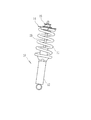
図1において、ロアアーム4にはショックアブソーバ10が固定されており、ショックアブソーバ10にはこれを取り巻くようにコイルばね11が取り付けられている。図2は、図1においてショックアブソーバ10及びその付属部品のみを図示した側面図である。シリンダ12内には、ピストン(図示せず)と一体のピストンロッド13の一部が埋設されている。ピストンロッド13の上端はアッパーマウント15に連結され、コイルばね11の上端にはばね受け部材14が固定されている。通常走行では、コイルばね11の伸縮によるばね力とショックアブソーバ10の減衰力により、路面からタイヤ2に作用する力を受け止めている。また、ショックアブソーバ10によりタイヤ2の上下動による車体の振動を減衰させることができる。
In FIG. 1, a
図3はタイヤ2及び車輪に外力が負荷されていない状態におけるハブキャリア6の近傍の要部を示す拡大斜視図であり、図4は図3と同じ状態における側面図である。アッパーアーム3とロアアーム4との間に、ハブキャリア6が連結されている。具体的には、図3においてハブキャリア6の円筒部20に、防振ゴムであるブッシング21が嵌め込まれ、ブッシング21の内径部である内筒22とアッパッパーアーム3又はロアアーム4に形成された孔をボルトが挿通して、アッパッパーアーム3又はロアアーム4に取り付けられている。この構成によれば路面や原動機からの振動入力を緩和させつつ、ハブキャリア6はタイヤ2及び車輪の上下動に追随することができる。
FIG. 3 is an enlarged perspective view showing a main part in the vicinity of the
図5は、ハブキャリア6の単体の斜視図である。本図は図3の図示とは異なり、ハブキャリア6を裏面側から見た状態を示している。図3〜図5に示したように、ハブキャリア6にはこれと一体に座面23が形成されている。この構成では、部品点数を増やすことなく座面23を追加できるので、軽量化及びコスト低減に有利になる。ハブキャリア6を鋳造部品又は鍛造部品とした場合は、座面23は本体部分と一体に成形できるので、座面23の形成が容易になる。
FIG. 5 is a perspective view of the
座面23はハブキャリア6の上部側に形成され、車軸の方向(矢印a方向)に延出している。図3及び図4に示したように、車体フレーム31にはストッパ取付体32が、例えば溶接により固定され、ストッパ取付体32にはストッパ30が固定されている。本実施形態では、座面23とストッパ30でタイヤ2の上下方向の動きのうち上方向の動きを制限するストッパ構造を構成している。通常走行のようにタイヤ2及び車輪に大きな外力が負荷されていない状態では、図3及び図4に示したように、座面23とストッパ30とは当接せず離れた状態となる。
The
ストッパ30の材料は、例えば天然ゴム又は合成ゴムである。ストッパ30のストッパ取付体32への固定は、ストッパ30をストッパ取付体32に設けた突起に嵌め込んでもよく、ストッパ30にさらに取付部材を接合し、ストッパ30をストッパ取付体32に設けたボルトに締め付けるようにしてもよい。
The material of the
車体フレーム31は、車体の一部を構成する部品である。本実施形態では、ストッパ30はストッパ取付体32を介して車体フレーム31に取り付けられているが、これに限るものではなく、車体の一部を構成する部分に固定されていればよい。すなわち、路面からタイヤ2及び車輪に入力された外力のうち、大きな負荷がハブキャリア6及びストッパ30を介して直接車体に伝わる構成であればよい。
The
車両が凹凸路や陥没路を走行し路面からの外力による大入力がタイヤ2及び車輪に負荷されると、図2においてショックアブソーバ10のピストンロッド13はシリンダ12内に埋没する方向に動き、ピストンロッド13のシリンダ12からの伸長量が縮小する。このことにより、コイルばね11が圧縮側に変形しタイヤ2と車体との間の間隔も縮小し、ピストンロッド13がオーバーストロークになると、タイヤ2(又はタイヤチェーン)の車体への干渉や、サスペンション、ブレーキ及び駆動系等において部品間の相互干渉や部品内部の相互干渉といった不具合が生じる。
When the vehicle travels on an uneven road or a depressed road and a large input from the road surface is loaded on the
このため、従来技術では例えば図2において、ピストンロッド13部分にストッパを挿通させ、ピストンロッド13の縮小量を制限し、タイヤの上方向の動きを制限していた。詳細は後に説明するとおり、本実施形態では外力による大入力の負荷により、タイヤ2が上方向に大きく動く場合、ハブキャリア6と一体に形成された座面23にストッパ30が当接し、タイヤ2の上方向の動きが制限される。このことにより、ピストンロッド13部分にはストッパを設けることなく、タイヤ2の上方向の動きを制限することができる。
For this reason, in the prior art, for example, in FIG. 2, a stopper is inserted through the
図6は座面23にストッパ30が当接した状態のハブキャリア6の近傍の要部を示す拡大斜視図であり、図7は図6と同じ状態における側面図である。図3及び図4のようにタイヤ2及び車輪に外力が負荷されていない状態から、路面からタイヤ2及び車輪へ外力による入力が負荷されると、座面23とストッパ30との間隔が縮まる。この入力が大きいと、最終的には図6及び図7に示したように、座面23にストッパ30が当接し、ストッパ30が所定の量だけ変形しタイヤ2の上方向の動きが制限される。より具体的には、ストッパ30はばね特性を有するので、座面23に当接した後、タイヤ2からの衝撃を吸収しながら、ある程度変形が進行した後、ばね定数が急激に上昇して剛体に近い特性になる。すなわち、ストッパ30は、座面23への当接直後は剛体的な特性は発揮しないので、ストッパ30の入力は車体へ急激に負荷されることはなく、車体の変形や破損は防止されることになる。
FIG. 6 is an enlarged perspective view showing a main part in the vicinity of the
一方、路面からタイヤ2及び車輪へ外力による大入力が負荷されると、車輪と一体にハブキャリア6が動き、ハブキャリア6の一部を構成する座面23が、車体と一体のストッパ30に当接する。すなわち、路面からタイヤ2及び車輪へ外力が負荷されたときに、ストッパと座面が当接したことによる入力は、ハブキャリア6への連結部品であるサスペンションアーム5やクロスメンバ7に負荷されることなく、ハブキャリア6及びストッパ30を介して直接車体に負荷されることになる。
On the other hand, when a large input from the road surface is applied to the
このため、ストッパ30からの負荷の対策のために、サスペンションアーム5やクロスメンバ6の強度を特別に高める必要性は生じない。ハブキャリア6には座面23の追加が必要になるが重量増は僅かなものであり、ハブキャリア6の補強が必要であっても、元々高い強度と剛性で設計されているため、大幅な補強は不要となる。このため、ハブキャリア6自体が重量増となっても大幅な重量増とはならず、車両懸架装置1全体として見れば軽量化になる。
Therefore, there is no need to specially increase the strength of the
すなわち、本実施形態によれば、車両懸架装置1を構成する部品の軽量化を図りつつストッパ構造を採用することができる。また、ハブキャリア6を鋳造部品又は鍛造部品とすれば、設計自由度が高く座面23の形成が容易になることに加え、別途取り付け部材は不要となるため、座面23の形成のための重量増加も僅かなものに抑えることができる。一方、座面23の追加により、図4に示したようにハブキャリア6の上部中央に構造体が追加されるため、強度向上(特にねじり強度)に寄与する。
In other words, according to the present embodiment, the stopper structure can be employed while reducing the weight of the parts constituting the
前記のような軽量化は、本実施形態に係る車両懸架装置1を備えた自動車の軽量化でもあるので、省エネルギー効果を奏し、特に電気自動車に有用である。電気自動車においては、航続距離の増大が求められており、軽量化は航続距離の増大に直接的に寄与するからである。前記のように、ストッパ30からの負荷の対策のために、サスペンションアーム5やクロスメンバ6の強度を特別に高める必要性は生じないことは、軽量化だけでなく構造の簡略化にも有利になる。また、ハブキャリア6に設ける座面23は、ストッパ30に当接可能な形状であればよく、簡素な形状で足りることになる。すなわち、本実施形態に係るストッパ構造を採用しても、重量が特別増えることもなく、部品が特別に複雑化することもなく、従来技術に比べコスト低減を図ることができる。
The weight reduction as described above is also a weight reduction of the automobile provided with the
ここで、前記のとおり、路面からタイヤ2及び車輪へ外力が負荷されたときに、ストッパと座面が当接したことによる入力は、ハブキャリア6への連結部品であるサスペンションアーム5やクロスメンバ7に負荷されることなく、ハブキャリア6及びストッパ30を介して直接車体に負荷されることになる。すなわち、サスペンションアーム5及びクロスメンバ7と、これらの間に介在するショックアブソーバ10に対しては、ストッパ30による入力が負荷されないため、サスペンションアーム5とハブキャリア6との間、サスペンションアーム6とクロスメンバ7との間、ショックアブソーバ10とサスペンションアーム5及びクロスメンバ7との間、さらに、クロスメンバ7と車体との間のそれぞれに介在する防振ゴムのばね定数を下げることができる。このことにより、外部から負荷される振動入力(路面や原動機からの振動入力)が一層緩和されので、車室内の振動騒音を低減することができる。
Here, as described above, when an external force is applied from the road surface to the
また、従来技術のように、ピストンロッド13部分にストッパを設ける構造では、ストッパからの負荷はショックアブソーバ10のアッパーマウント15(図2参照)に直接印加される。このため、アッパーマウント15に用いるマウントゴムは硬度を高める必要があり、このことは、通常走行時における振動騒音の原因となっていた。本実施形態は前記のとおり、ピストンロッド13部分にストッパを設ける構造ではないため、ハブキャリア6に設けた座面23からの負荷がストッパ30に負荷されてもアッパーマウント15(図2参照)には負荷されない。このため、アッパーマウント15に用いるマウントゴムの硬度を高める必要も生じず、マウントゴムによる振動騒音を低減させることができる。
Further, in the structure in which the
本実施形態に係る車両懸架装置は、ダブルウィッシュボーン式サスペンションの例で説明したがこれに限るものではなく、例えばマルチリンク式サスペンションであってもよい。いずれの形式のサスペンションであっても、路面からタイヤ2及び車輪へ負荷された外力による入力が、軸受及び車軸を介して車輪と直結する部品であるハブキャリア及びストッパ30を介して直接車体に負荷される構成にすればよい。
Although the vehicle suspension apparatus according to the present embodiment has been described with the example of the double wishbone suspension, the present invention is not limited to this, and may be a multi-link suspension, for example. Regardless of the type of suspension, the external force applied to the
また、本実施形態においては、ストッパ30はストッパ取付体32を介し車体フレーム31に固定し、座面23はハブキャリア6に設けた例で説明したが、ストッパ30と座面23との位置関係を逆にしてもよい。この場合、例えばストッパ30はハブキャリア6に設けた取付体に取り付け、座面23は車体フレーム31の一部で座面23を兼ねるようにしてもよい。ハブキャリア6にストッパ30の取付体を設ける場合は、取付体を前記ハブキャリア6と一体に形成すれば、部品点数を増やすことなく取付体を追加できるので、軽量化及びコスト低減に有利になる。
In the present embodiment, the
また、前記のとおり、本実施形態に係る車両懸架装置は軽量化を図ることができるので、特に電気自動車に有用であるが、これに限定されものではなく、車両懸架装置を備える車両全般に適用可能である。電気自動車に適用する場合は、例えばインホイールモータを支持する車両懸架装置に適用することができる。インホイールモータは車輪の内側に内蔵して用いられ、その回転により車輪が回転しこれと一体に車輪に装着されたタイヤが回転する。 In addition, as described above, the vehicle suspension device according to the present embodiment can be reduced in weight, and thus is particularly useful for an electric vehicle. However, the present invention is not limited to this, and is applicable to all vehicles including the vehicle suspension device. Is possible. When applied to an electric vehicle, for example, it can be applied to a vehicle suspension device that supports an in-wheel motor. The in-wheel motor is used by being built inside the wheel. The rotation of the in-wheel motor rotates the tire attached to the wheel.
1 車両懸架装置
2 タイヤ
3 アッパーアーム
4 ロアアーム
5 サスペンションアーム
6 ハブキャリア
7 クロスメンバ
10 ショックアブソーバ
11 コイルばね
13 ピストンロッド
15 アッパーマウント
23 座面
30 ストッパ
31 車体フレーム
DESCRIPTION OF
Claims (2)
上下一対のアッパーアームとロアアームとで構成されるサスペンションアームを連結し、軸受及び車軸を介して車輪と直結するハブキャリアと、
前記ロアアームに固定されたショックアブソーバと、
前記ショックアブソーバを取り巻くように前記ショックアブソーバに取り付けられたコイルばねと、
前記車輪に装着されたタイヤの上下方向の動きのうち上方向の動きを制限するストッパ構造とを備えており、
前記ストッパ構造は、前記ハブキャリアに設けた座面と車体に設けたストッパで構成しており、
前記ハブキャリアは、前記サスペンションアームの上側にある前記アッパーアームに、前記ハブキャリアに形成された円筒部に嵌め込まれたブッシングを介して取り付けられており、
前記ハブキャリアの車軸方向側面視において、前記円筒部は前記ハブキャリアの左右両側に形成されており、前記左右両側の前記円筒部の間に前記座面があり、
前記上下方向において、前記ハブキャリアに設けた前記座面は前記ハブキャリアの円筒部の中心軸よりも下側にあることを特徴とする車両懸架装置。 A vehicle suspension device for supporting an in-wheel motor of an electric vehicle,
A hub carrier that connects a suspension arm composed of a pair of upper and lower upper arms and a lower arm and is directly connected to a wheel via a bearing and an axle,
A shock absorber fixed to the lower arm;
A coil spring attached to the shock absorber so as to surround the shock absorber;
A stopper structure that limits the upward movement of the vertical movement of the tire mounted on the wheel, and
The stopper structure is constituted by stopper path provided on the seat and the vehicle body which is provided on the hub carrier,
The hub carrier is attached to the upper arm on the upper side of the suspension arm via a bushing fitted in a cylindrical portion formed in the hub carrier,
In the side view in the axle direction of the hub carrier, the cylindrical portion is formed on both the left and right sides of the hub carrier, and the seating surface is between the cylindrical portions on the left and right sides,
The vehicle suspension device according to claim 1, wherein the seat surface provided on the hub carrier is located below a central axis of a cylindrical portion of the hub carrier in the vertical direction.
Priority Applications (1)
| Application Number | Priority Date | Filing Date | Title |
|---|---|---|---|
| JP2016015864A JP6297077B2 (en) | 2016-01-29 | 2016-01-29 | Vehicle suspension system |
Applications Claiming Priority (1)
| Application Number | Priority Date | Filing Date | Title |
|---|---|---|---|
| JP2016015864A JP6297077B2 (en) | 2016-01-29 | 2016-01-29 | Vehicle suspension system |
Publications (2)
| Publication Number | Publication Date |
|---|---|
| JP2017132418A JP2017132418A (en) | 2017-08-03 |
| JP6297077B2 true JP6297077B2 (en) | 2018-03-20 |
Family
ID=59502094
Family Applications (1)
| Application Number | Title | Priority Date | Filing Date |
|---|---|---|---|
| JP2016015864A Active JP6297077B2 (en) | 2016-01-29 | 2016-01-29 | Vehicle suspension system |
Country Status (1)
| Country | Link |
|---|---|
| JP (1) | JP6297077B2 (en) |
Family Cites Families (4)
| Publication number | Priority date | Publication date | Assignee | Title |
|---|---|---|---|---|
| JPS6286207U (en) * | 1985-11-20 | 1987-06-02 | ||
| JPS6365505U (en) * | 1986-10-17 | 1988-04-30 | ||
| JPH1058932A (en) * | 1996-08-09 | 1998-03-03 | Toyota Motor Corp | Independent suspension type suspension for steering wheels |
| JP2008183984A (en) * | 2007-01-29 | 2008-08-14 | Mazda Motor Corp | Arrangement structure of vehicle driving device |
-
2016
- 2016-01-29 JP JP2016015864A patent/JP6297077B2/en active Active
Also Published As
| Publication number | Publication date |
|---|---|
| JP2017132418A (en) | 2017-08-03 |
Similar Documents
| Publication | Publication Date | Title |
|---|---|---|
| KR101479594B1 (en) | Insulator of suspension | |
| KR100980877B1 (en) | Trailing arm assembly for suspension system | |
| JP6297077B2 (en) | Vehicle suspension system | |
| KR101361246B1 (en) | Coupled torsion beam axle for vehicle | |
| JP2003276414A (en) | Front of commercial vehicle and suspension system for dead axle | |
| KR20110060562A (en) | Lower arm bush unit for vehicle | |
| KR100656605B1 (en) | Strut insulator structure | |
| JP2015123952A (en) | Trunnion bracket | |
| KR101941920B1 (en) | A Auto Suspension System With Rubber Suspension Unit And A Automobile Using Auto Suspension System With Rubber Suspension Unit Thereof | |
| KR20140062628A (en) | Bush structure | |
| KR20080023557A (en) | Strut mount structure of suspension for automobile | |
| KR20100008980A (en) | Trailing arm bush unit for vehicle | |
| KR20080042345A (en) | Automobile suspension | |
| JP2001221273A (en) | Shock absorber mounting structure | |
| KR101028545B1 (en) | Radius rod unit for vehicle | |
| KR20040033803A (en) | Lower control arm bush for suspension of vehicles | |
| JP6514545B2 (en) | Strut type suspension system | |
| KR20050006804A (en) | suspension system | |
| KR20040000177A (en) | a superstucture for mounting of shock absorber | |
| KR100831495B1 (en) | Structure of stabilizer bar for automobile | |
| JP5544216B2 (en) | Suspension device | |
| KR200187362Y1 (en) | Fixing structure of rear lower arm for a car | |
| KR20090052046A (en) | Suspenssion bush | |
| KR20010045889A (en) | Shock-absorber mounting structure of vehicles | |
| KR100862267B1 (en) | Trailing arm bush of vehicle |
Legal Events
| Date | Code | Title | Description |
|---|---|---|---|
| A02 | Decision of refusal |
Free format text: JAPANESE INTERMEDIATE CODE: A02 Effective date: 20161101 |
|
| A521 | Request for written amendment filed |
Free format text: JAPANESE INTERMEDIATE CODE: A523 Effective date: 20171226 |
|
| A61 | First payment of annual fees (during grant procedure) |
Free format text: JAPANESE INTERMEDIATE CODE: A61 Effective date: 20180220 |
|
| R150 | Certificate of patent or registration of utility model |
Ref document number: 6297077 Country of ref document: JP Free format text: JAPANESE INTERMEDIATE CODE: R150 |
|
| R250 | Receipt of annual fees |
Free format text: JAPANESE INTERMEDIATE CODE: R250 |
|
| R250 | Receipt of annual fees |
Free format text: JAPANESE INTERMEDIATE CODE: R250 |
|
| R250 | Receipt of annual fees |
Free format text: JAPANESE INTERMEDIATE CODE: R250 |
|
| R250 | Receipt of annual fees |
Free format text: JAPANESE INTERMEDIATE CODE: R250 |