JP6292474B2 - Belt device and image forming apparatus having the same - Google Patents
Belt device and image forming apparatus having the same Download PDFInfo
- Publication number
- JP6292474B2 JP6292474B2 JP2014053522A JP2014053522A JP6292474B2 JP 6292474 B2 JP6292474 B2 JP 6292474B2 JP 2014053522 A JP2014053522 A JP 2014053522A JP 2014053522 A JP2014053522 A JP 2014053522A JP 6292474 B2 JP6292474 B2 JP 6292474B2
- Authority
- JP
- Japan
- Prior art keywords
- belt
- secondary transfer
- transfer belt
- contact
- roller
- Prior art date
- Legal status (The legal status is an assumption and is not a legal conclusion. Google has not performed a legal analysis and makes no representation as to the accuracy of the status listed.)
- Active
Links
Images


Landscapes
- Electrophotography Configuration And Component (AREA)
- Electrostatic Charge, Transfer And Separation In Electrography (AREA)
Description
本発明は、複数の支持回転体に張架されて走行する無端状のベルト部材を備えるベルト装置、及び、これを備えた複写機、プリンタ、ファクシミリ等の画像形成装置に関するものである。 The present invention relates to a belt device including an endless belt member that is stretched around a plurality of support rotating bodies, and an image forming apparatus such as a copying machine, a printer, and a facsimile including the belt device.
電子写真プロセスを用いた画像形成装置としては、潜像担持体上に形成した各色のトナー像を中間転写体に一次転写した後に、シート材に対して二次転写するカラー画像形成装置が知られている。この種の画像形成装置における二次転写装置には、ローラ転写方式とベルト転写方式がある。ローラ転写方式は、中間転写体と転写ローラとの間でシート材を挟持して搬送しながら二次転写を行う方式である。一方、ベルト転写方式は、二次転写装置の二次転写ローラを含む支持ローラ間に張架した無端状の搬送ベルトと中間転写体との間でシート材を挟持して搬送しながら二次転写を行う方式である。ベルト転写方式は、中間転写体との間でシート材を挟持する箇所のシート材搬送方向上流側及び下流側の少なくとも一方の二次転写ベルト部分で、シート材を保持して搬送する。そのため、中間転写体との間でシート材を挟持する箇所だけでなく、そのシート材搬送方向上流側や下流側でも、シート材を保持して搬送力を付与できる。よって、ベルト転写方式は、一般に、シート材の安定搬送に関してローラ転写方式よりも好適である。 As an image forming apparatus using an electrophotographic process, a color image forming apparatus is known in which a toner image of each color formed on a latent image carrier is primarily transferred to an intermediate transfer member and then secondarily transferred to a sheet material. ing. Secondary transfer devices in this type of image forming apparatus include a roller transfer method and a belt transfer method. The roller transfer method is a method in which secondary transfer is performed while a sheet material is sandwiched and conveyed between an intermediate transfer member and a transfer roller. On the other hand, in the belt transfer system, the secondary transfer is performed while the sheet material is sandwiched and conveyed between an endless conveyance belt and an intermediate transfer member that are stretched between support rollers including the secondary transfer roller of the secondary transfer device. It is a method to perform. In the belt transfer method, the sheet material is held and conveyed by at least one secondary transfer belt portion on the upstream side and the downstream side in the sheet material conveyance direction where the sheet material is sandwiched between the intermediate transfer member. For this reason, the sheet material can be held and imparted with conveying force not only at the location where the sheet material is sandwiched between the intermediate transfer member but also at the upstream side and downstream side in the sheet material conveying direction. Therefore, the belt transfer method is generally preferable to the roller transfer method with respect to the stable conveyance of the sheet material.
このベルト転写方式は、一般的なベルト装置と同様、二次転写ベルトがベルト幅方向の一端側へ寄ったり(ベルト寄り)、ベルト幅方向の各端部へ向かうベルト寄りが繰り返されるベルト蛇行が生じたりする現象が発生し得る。ベルト寄り(ベルト蛇行を含む。)は、二次転写装置を構成する構造体の組付け寸法公差、例えば二次転写ベルトを張架支持する複数の支持ローラの回転軸の平行度やローラ外径のばらつき、二次転写ベルト自体の周長変化による張力の不均一化などが原因で発生する。これらの原因によって二次転写ベルトが直線走行せずにベルト幅方向に変位した状態で走行することで、その変位した方向に寄せられてベルト寄りが発生する。 In this belt transfer system, as in a general belt device, the secondary transfer belt moves toward one end in the belt width direction (belt shift), or the belt meandering is repeated such that the belt shift toward each end in the belt width direction is repeated. A phenomenon that occurs may occur. Near the belt (including belt meandering) is an assembly size tolerance of the structure constituting the secondary transfer device, for example, the parallelism of the rotation shafts of the plurality of support rollers that support the secondary transfer belt and the outer diameter of the rollers. This is caused by unevenness in tension, non-uniform tension due to a change in peripheral length of the secondary transfer belt itself, and the like. Due to these causes, the secondary transfer belt travels in a state of being displaced in the belt width direction without traveling in a straight line, so that the belt is displaced in the displaced direction.
従来、ベルト寄りによるベルトの幅方向移動範囲を一定の規制範囲内に収めるために、種々のベルト寄り規制手段が提案されている。
例えば、特許文献1には、中間転写ベルトや二次転写ベルトを張架する複数の支持ローラの少なくとも1つに、傾動可能な傾動回転体としてのステアリングローラを用い、ベルト寄りの発生を検知したらステアリングローラを傾かせて、ベルト寄りを戻す方向にベルトを移動させる軸傾斜方式のベルト寄り規制手段が開示されている。この特許文献1に開示されたベルト寄り規制手段は、ベルト寄りの発生を検知する検知手段が設けられており、その検知手段の検知結果に基づいてステアリングローラの傾斜量を制御するものである。
Conventionally, various belt deviation regulating means have been proposed in order to keep the movement range of the belt in the width direction due to the belt deviation within a certain regulation range.
For example, in Patent Document 1, if at least one of a plurality of support rollers that stretch an intermediate transfer belt or a secondary transfer belt is used as a tilting rotating body that can tilt, and the occurrence of belt deviation is detected. An axis inclination type belt deviation regulating means for moving the belt in a direction in which the steering roller is inclined to return the belt deviation is disclosed. The belt deviation regulating means disclosed in Patent Document 1 is provided with a detection means for detecting the occurrence of belt deviation, and controls the amount of inclination of the steering roller based on the detection result of the detection means.
上記特許文献1では、転写後の中間転写ベルトや二次転写ベルトの表面のクリーニングについては触れられていないが、必要であれば転写残トナーの除去のために当接部材としてのクリーニング用のブレードを設け、さらには廃トナーの漏れ防止のために当接部材としてのシール部材を設けることが考えられる。クリーニング用のブレードは中間転写ベルトや二次転写ベルトの表面に対して食い込む形で当接し、シール部材もクリーニング用のブレードによるクリーニング箇所のベルト走行方向の上流側に中間転写ベルトや二次転写ベルトの表面に食い込む形で当接して配置される。ところが、上記特許文献1のベルト装置では、ステアリングローラを傾斜させることでベルト部材の移動方向と直交する幅方向におけるベルト部材の位置を調整している。このため、例えばステアリングローラの一端側が他端側に対し相対的に過度に押し上げられると、中間転写ベルトや二次転写ベルトが例えばシール部材に対し上方に変位する。この結果、シール部材の先端部が中間転写ベルトや二次転写ベルトの表面から離れ、その箇所ではシール部材の先端部と、中間転写ベルトや二次転写ベルトの表面との間に隙間が発生し、除去した廃トナーがその隙間からシール部材の外側に飛散してしまうという問題が生じ得る。逆に、上記一端側が他端側に対し相対的に過度に押し下げられると、シール部材の先端部が中間転写ベルトや二次転写ベルトの表面に過度に押し当てられ、クリーニング用のブレードやシール部材の先端部が不要に摩耗し、クリーニング性やシール性が不十分になってしまうという問題もあった。 The above-mentioned Patent Document 1 does not mention cleaning of the surfaces of the intermediate transfer belt and the secondary transfer belt after transfer, but if necessary, a cleaning blade as a contact member for removing transfer residual toner. Further, it is conceivable to provide a seal member as a contact member for preventing leakage of waste toner. The cleaning blade comes into contact with the surface of the intermediate transfer belt or the secondary transfer belt so as to bite, and the seal member is also upstream of the intermediate belt or secondary transfer belt in the belt running direction of the cleaning portion by the cleaning blade. It is arranged so as to abut on the surface of the surface. However, in the belt device of Patent Document 1, the position of the belt member in the width direction orthogonal to the moving direction of the belt member is adjusted by inclining the steering roller. For this reason, for example, when one end side of the steering roller is excessively pushed up with respect to the other end side, the intermediate transfer belt and the secondary transfer belt are displaced upward with respect to the seal member, for example. As a result, the tip of the seal member is separated from the surface of the intermediate transfer belt or the secondary transfer belt, and a gap is generated between the tip of the seal member and the surface of the intermediate transfer belt or the secondary transfer belt. Then, there may be a problem that the removed waste toner is scattered from the gap to the outside of the seal member. Conversely, when the one end side is excessively pressed down relative to the other end side, the tip of the seal member is excessively pressed against the surface of the intermediate transfer belt or the secondary transfer belt, and the cleaning blade or seal member There is also a problem that the tip part of the metal wears unnecessarily, resulting in insufficient cleaning and sealing.
本発明は以上の問題点に鑑みなされたものであり、その目的は、当接部材のベルト部材の表面への押し当てを適切に行い、当接部材のベルト部材との当接箇所での隙間の発生を抑制できるベルト装置、及び、これを備えた画像形成装置を提供することである。 The present invention has been made in view of the above-described problems, and an object of the present invention is to appropriately press the contact member against the surface of the belt member and to form a gap at the contact portion of the contact member with the belt member. It is an object of the present invention to provide a belt device capable of suppressing the occurrence of the above and an image forming apparatus including the belt device.
上記目的を達成するために、請求項1の発明は、複数の支持回転体に張架されて走行する無端状のベルト部材と、前記複数の支持回転体の少なくとも一つの回転軸における一端側と他端側の少なくとも一方を変位して傾動させることで、前記ベルト部材がベルト幅方向へ移動するベルト寄りの補正を行う傾動回転体と、該傾動回転体に対し前記ベルト部材の走行方向における上流側と下流側の少なくとも一方の支持回転体と前記傾動回転体との間で張られ、かつ前記支持回転体と前記傾動回転体とに巻き付けている前記ベルト部材の走行方向における巻き付け領域を除く前記ベルト部材のテンション部分の表面に当接する、装置本体側に固定された当接部材とを備えたベルト装置において、複数の支持回転体のうち傾動しない支持回転体の回転軸に直交する断面において、前記当接部材が存在しないと仮定した状態で前記ベルト部材の表面がとる表面位置に対し、前記ベルト部材が存在しないと仮定した状態で前記当接部材のベルト側先端がベルト裏面側に突出する量である前記当接部材の食い込み量に応じ、前記当接部材の前記ベルト部材との当接箇所から前記支持回転体に巻き付けている前記ベルト部材の走行方向における巻き付け領域の端までの前記テンション部分の長さが変化し、当該長さの最大値が前記支持回転体の半径の長さとなるように、前記当接部材の固定位置を設定したことを特徴とするものである。 In order to achieve the above object, the invention of claim 1 includes an endless belt member that is stretched around a plurality of supporting rotating bodies, and one end side of at least one rotating shaft of the plurality of supporting rotating bodies. Displacement and tilting of at least one of the other end side allows the belt member to be moved in the belt width direction to correct the belt shift, and the upstream of the belt member in the running direction of the belt member. Excluding a winding region in a running direction of the belt member that is stretched between at least one of the support rotating body on the side and the downstream side and the tilting rotating body and wound around the support rotating body and the tilting rotating body. abuts against the surface of the tension portion of the belt member, the belt device including an abutment member fixed to the apparatus main body side, supporting rotator times without tilting of the plurality of supporting rotating bodies In the cross section orthogonal to the axis, the front end of the contact member on the belt side in a state where the belt member is assumed to be absent from the surface position taken by the surface of the belt member in the state where the contact member is not present. Winding of the belt member wound in the running direction from the contact portion of the contact member with the belt member according to the amount of biting of the contact member, which is an amount protruding toward the back side of the belt The fixing position of the abutting member is set so that the length of the tension portion to the end of the region changes, and the maximum value of the length is the length of the radius of the support rotating body. Is.
本発明によれば、当接部材のベルト部材の表面への押し当てを適切に行い、当接部材のベルト部材との当接箇所での隙間の発生を抑制できるベルト装置、及び、これを備えた画像形成装置を提供することである。 According to the present invention, there is provided a belt device capable of appropriately pressing the contact member against the surface of the belt member and suppressing the occurrence of a gap at the contact portion between the contact member and the belt member, and the belt device. An image forming apparatus is provided.
以下、本発明を電子写真方式の画像形成装置であるプリンタに適用した一実施形態について、図面を参照して説明する。
図1は、本実施形態に係るプリンタを示す概略構成図である。
本プリンタに、その本体筐体内に配置された4つの感光体1a,1b,1c,1dが設けられている。各感光体上には互いに異なる色のトナー像がそれぞれ形成される。具体的には、これらの感光体1a,1b,1c,1d上に、ブラックトナー像、マゼンタトナー像、シアントナー像及びイエロートナー像がそれぞれ形成される。なお、本実施形態における各感光体1a,1b,1c,1dはドラム状に形成されているが、複数のローラに巻き掛けられて回転駆動される無端ベルト状の感光体を用いることもできる。
Hereinafter, an embodiment in which the present invention is applied to a printer which is an electrophotographic image forming apparatus will be described with reference to the drawings.
FIG. 1 is a schematic configuration diagram illustrating a printer according to the present embodiment.
The printer is provided with four photoconductors 1a, 1b, 1c, and 1d arranged in the main body casing. Different color toner images are formed on the respective photoreceptors. Specifically, a black toner image, a magenta toner image, a cyan toner image, and a yellow toner image are formed on these photoreceptors 1a, 1b, 1c, and 1d, respectively. Note that each of the photoreceptors 1a, 1b, 1c, and 1d in the present embodiment is formed in a drum shape, but an endless belt-like photoreceptor that is wound around a plurality of rollers and driven to rotate can also be used.
4つの感光体1a,1b,1c,1dに対向して、像担持体である中間転写体として、無端ベルト状部材の中間転写ベルト51が配置されている。各感光体1a,1b,1c,1dの外周面は、それぞれ中間転写ベルト51の外周面に当接している。本実施形態の中間転写ベルト51は、テンションローラ52、駆動ローラ53、斥力ローラ54、入口ローラ55等の支持ローラ(支持回転体)に巻き掛けられ、張架されている。これらの支持ローラのうちの1つである駆動ローラ53は、図示しない駆動源によって回転駆動し、この駆動ローラ53の回転駆動により中間転写ベルト51が図1中の矢印Aの方向に走行する。
An
中間転写ベルト51は、多層構造のものでも単層構造のものでもよい。多層構造のベルトで構成する場合、例えば、伸びの少ないフッ素樹脂やPVDFシート、ポリイミド系樹脂でベース層を形成し、ベルト外周面をフッ素系樹脂等の平滑性のよいコート層で構成するものが好ましい。一方、単層構造のベルトで構成する場合には、PVDF、PC、ポリイミド等の材質を用いるものがよい。
The
各感光体1a,1b,1c,1d上に各色トナー像を形成する構成及び動作、並びに、各色トナー像を中間転写ベルト51上に一次転写する構成及び動作は、ほぼ同様であり、形成される各色トナー像の色が異なるだけである。よって、以下、ブラック用感光体1aにブラックトナー像を形成し、そのトナー像を中間転写ベルト51上に一次転写する構成及び動作について説明し、他の色については説明を省略する。
The configuration and operation for forming each color toner image on each photoconductor 1a, 1b, 1c, 1d and the configuration and operation for primary transfer of each color toner image onto the
ブラック用感光体1aは、図1中の反時計回り方向に回転駆動する。感光体1aの外周面には、図示しない除電装置からの光が照射されることで、感光体1aの表面電位が初期化される。初期化された感光体外周面は、帯電装置8aによって所定の極性(本実施形態ではマイナス極性)に一様に帯電される。このようにして帯電された感光体外周面は、図示しない露光装置から出射される光変調されたレーザビームLが照射され、これにより感光体1aの外周面上に静電潜像が形成される。本実施形態においては、レーザビームLを出射する露光装置がレーザ書き込み装置で構成されているが、例えばLEDアレイと結像手段を有する露光装置などを用いることもできる。感光体1aに形成された静電潜像は、現像装置10aと対向する現像領域を通過する際に、ブラックトナー像として可視像化される。
The black photoconductor 1a is driven to rotate counterclockwise in FIG. The surface potential of the photoconductor 1a is initialized by irradiating the outer peripheral surface of the photoconductor 1a with light from a static eliminator (not shown). The initialized outer peripheral surface of the photoconductor is uniformly charged to a predetermined polarity (in this embodiment, a negative polarity) by the charging
中間転写ベルト51の内周面側には、感光体1aと対向する位置に一次転写ローラ11aが配置されている。この一次転写ローラ11aが中間転写ベルト51の内周面に当接することで、感光体1aと中間転写ベルト51との間に適正な一次転写ニップが確保されている。一次転写ローラ11aには、感光体1a上に形成されたトナー像のトナー帯電極性と逆極性(本実施形態ではプラス極性)の一次転写電圧が印加される。これにより、感光体1aと中間転写ベルト51との間に一次転写電界が形成され、感光体1a上のトナー像が、その感光体1aと同期して回転駆動される中間転写ベルト51上に静電的に一次転写される。トナー像を中間転写ベルト51に一次転写した後の感光体1aの外周面に付着する転写残トナーは、クリーニング装置12aによって除去され、感光体1aの外周面が清掃される。
On the inner peripheral surface side of the
4色のトナー像をすべて使うフルカラーモードにおいては、他の色の感光体1b,1c,1dについても、同様に、マゼンタトナー像、シアントナー像及びイエロートナー像がそれぞれ形成される。そして、これらの各色トナー像は、中間転写ベルト51上に一次転写されているブラックトナー像に重ね合わさるようにして、順次一次転写される。
In the full color mode using all four color toner images, magenta toner images, cyan toner images, and yellow toner images are similarly formed on the photoconductors 1b, 1c, and 1d of other colors. These color toner images are sequentially primary-transferred so as to be superimposed on the black toner image primarily transferred onto the
一方、ブラック単色モードにおいては、図示しない接離機構により、一次転写ローラ11b,11c,11dを感光体1b,1c,1dから離間させることで、マゼンタ、シアン、イエロー用の感光体1b,1c,1dを中間転写ベルト51から離間させる。そして、ブラック感光体1aのみが中間転写ベルト51に当接した状態で、ブラックトナー像のみが中間転写ベルト51に一次転写される。
On the other hand, in the black monochromatic mode, the
また、図1に示すように、プリンタ本体内の下部には、給紙装置14が配置されている。給紙装置14は、給紙ローラ15の回転によって、シート材としての転写紙Pを図中矢印Bの方向へ送り出す。送り出された転写紙Pは、レジストローラ対16により、所定のタイミングで斥力ローラ54に巻き掛けられた中間転写ベルト51の部分と、これに対向配置された二次転写ベルト61の部分とが当接している二次転写ニップへと給送される。このとき、斥力ローラ54には所定の二次転写電圧が印加され、これによって中間転写ベルト51上のトナー像が転写紙Pに二次転写される。
As shown in FIG. 1, a paper feeding device 14 is disposed at the lower part of the printer body. The sheet feeding device 14 feeds the transfer sheet P as a sheet material in the direction of the arrow B in the drawing by the rotation of the
無端状のベルト部材としての二次転写ベルト61は、第2支持回転体としての傾斜回転体である分離ローラ63と、第2支持回転体としての二次転写ローラ62とに張架支持されている。本実施形態では、二次転写ローラ62が駆動ローラとなって回転駆動することで、二次転写ベルト61は、図1中の矢印Cの方向に走行する。トナー像が二次転写された転写紙Pは、二次転写ベルト61の外周面に静電的に吸着した状態で、二次転写ベルト61の走行に伴って搬送される。そして、転写紙Pは、分離ローラ63に巻き付いた二次転写ベルト61の部分の曲率によって二次転写ベルト61の外周面から分離し、二次転写ベルト61の転写紙搬送方向下流側に配置されている搬送ベルト17によって更に転写紙搬送方向下流側へ搬送される。この搬送ベルト17は、入口回転体としての駆動ローラである入口ローラ17Aと従動回転体である従動ローラ17Bとに張架されている。そして、転写紙Pが定着装置18を通る際に、転写紙P上のトナー像が熱と圧力の作用により転写紙Pに定着される。定着装置18を通過した転写紙Pは、排紙部に設けられた排紙ローラ対19を通って機外に排出される。
The
また、トナー像を二次転写した後の中間転写ベルト51上に付着する転写残トナーは、ベルトクリーニング装置20によって除去される。本実施形態におけるベルトクリーニング装置20では、ウレタン等で形成されたブレード形状のクリーニングブレード21を用いており、そのクリーニングブレード21を中間転写ベルト51の走行方向に対してカウンタ方向から当接させている。なお、ベルトクリーニング装置20には適宜様々な種類のものを用いることが可能であり、例えば、クリーニング装置を静電式のものとしてもよい。
Further, the transfer residual toner adhering to the
次に、二次転写ベルト61を備えた二次転写装置60におけるベルト寄り規制手段の構成及び動作について説明する。
本実施形態における二次転写装置60のベルト寄り規制手段は、軸傾斜方式であり、二次転写ベルト61を張架する一方の支持ローラである分離ローラ63の回転軸63aを傾斜させることで、二次転写ベルト61のベルト寄り範囲を所定の規制範囲内に規制する軸傾斜機構70で構成されている。
Next, the configuration and operation of the belt deviation regulating means in the
The belt shift restricting means of the
図2は、組み付け直後における二次転写装置60の軸傾斜機構の構成を、分離ローラ63の軸方向から見たときの模式図である。図3は、ベルト寄り規制後における軸傾斜機構の構成を、分離ローラ63の軸方向から見たときの模式図である。
FIG. 2 is a schematic diagram of the configuration of the shaft tilting mechanism of the
本実施形態の二次転写ローラ62の回転軸各端部には、それぞれ、図示しない軸受部材が取り付けられている。各軸受部材は、二次転写ローラ62の軸方向両端側に位置する二次転写装置60の2つのフレーム(軸端保持部材)68にそれぞれ保持される。これにより、二次転写ローラ62は、フレーム68に対して回転自在に支持される。
A bearing member (not shown) is attached to each end of the rotary shaft of the
また、本実施形態の分離ローラ63の回転軸各端部は、フレーム68よりも更に軸方向外側に配置される2つの回転軸支持アーム64にそれぞれ保持されたスライド軸受部65に取り付けられる。これにより、分離ローラ63は、回転軸支持アーム64に対して回転自在に支持される。
Further, each end portion of the rotation shaft of the
各回転軸支持アーム64は、二次転写ローラ62の回転軸62aの各端部に対して回動自在に取り付けられており、二次転写装置60のフレーム68に一端が固定されたアームスプリング66によって、図2中で時計回り方向に付勢されている。二次転写ベルト61にベルト寄りが生じていない、組み付け直後の状態においては、アームスプリング66の付勢力により、フレーム68の端部(不図示)に回転軸支持アーム64の端部が突き当たり、その突き当たり位置で回転軸支持アーム64の回動位置が保持される(図2)。
Each rotary
また、各回転軸支持アーム64は、図2及び図3に示すように、分離ローラ63を軸受けするスライド軸受部65を、回転軸支持アーム64の回転中心から径方向にスライド可能に保持している。スライド軸受部65は、回転軸支持アーム64に対し、テンションスプリング67により、回転軸支持アーム64の回転中心から径方向に径方向外側に向けて付勢されている。これにより、分離ローラ63は、常に二次転写ローラ62から離れる方向への付勢力を受け、分離ローラ63と二次転写ローラ62とに張架される二次転写ベルト61に所定のテンション(張力)を付与することができる。
As shown in FIGS. 2 and 3, each rotary
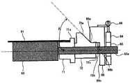
図4は、二次転写装置60の軸傾斜機構70の構成を、分離ローラ63の回転軸63aに沿って切断した切断面で示した模式図である。
分離ローラ63には、分離ローラ63とスライド軸受部65との間の回転軸63a上に、軸方向変位部材を構成するベルト寄り検知部材71及び軸傾斜部材72が設けられている。ベルト寄り検知部材71は、二次転写ベルト61の端部と接触するフランジ部71aを備えている。二次転写ベルト61がベルト幅方向へ移動して二次転写ベルト61の端部がフランジ部71aに当接すると、その力を受けて、ベルト寄り検知部材71は分離ローラ63の回転軸63aに沿って軸方向外側へ移動する。ベルト寄り検知部材71が回転軸63aに沿って軸方向外側へ移動すると、ベルト寄り検知部材71に対して回転軸63aの更に外側には配置されている軸傾斜部材72も回転軸63aに沿って軸方向外側へ移動する。
FIG. 4 is a schematic diagram showing the configuration of the shaft tilt mechanism 70 of the
The
また、軸傾斜部材72の傾斜面72aには、回転軸63aの軸方向外側から、固定部材であるフレーム68の当接部68aが当接している。このとき、当該軸傾斜部材72が設けられている分離ローラ63の回転軸63aの端部は、スライド軸受部65を介して、アームスプリング66によって付勢されている回転軸支持アーム64に支持されているため、図4中の上側に向かう付勢力を受けている。そのため、ベルト寄り検知部材71のフランジ部71aに二次転写ベルト61の端部が当接していない状態であれば、アームスプリング66の付勢力により、軸傾斜部材72の傾斜面72aの下端に連続している被ストッパ面72bに、フレーム68のストッパ面68bが当接する。この当接位置で、軸傾斜部材72の傾斜面72aとフレーム68の当接部68aとの当接位置が規制される。すなわち、フレーム68の当接部68aが軸傾斜部材72の傾斜面72aの下端部分に当接した状態で保持される。被ストッパ面72cに、フレーム68のストッパ面68cが当接する位置で、軸傾斜部材72とフレーム68との当接位置が規制される。
Further, a
この状態から、二次転写ベルト61がベルト幅方向外側へ移動する力を受けて、ベルト寄り検知部材71及び軸傾斜部材72が回転軸63aに沿って軸方向外側へ移動すると、軸傾斜部材72の傾斜面72aに沿ってフレーム68の当接部68aが相対的に移動する。これにより、軸傾斜部材72の傾斜面72aとフレーム68の当接部68aとの当接位置が傾斜面72aの上側へ変位する。その結果、二次転写ベルト61が移動する方向の軸方向端部側における分離ローラ63の回転軸63aの一端部は、図5に示すように、アームスプリング66の付勢力に抗して押し下げられる。このとき、二次転写ベルト61が移動する方向とは逆側の分離ローラ63の回転軸63aの端部は、二次転写ベルト61の端部がベルト寄り検知部材71のフランジ部71aに接触していない。このため、図4に示すように、フレーム68の当接部68aが軸傾斜部材72の傾斜面72aの下端部分に当接した状態で保持されている。これにより、二次転写ベルト61が移動する方向に対し、分離ローラ63の回転軸63aの他端側は、押し下げられた状態の回転軸63aの一端側に対して相対的に上方に位置する状態となる。よって、分離ローラ63の回転軸63aは傾斜することになる。
From this state, when the
このようにして分離ローラ63の回転軸63aが傾斜するにつれて、二次転写ベルト61のベルト幅方向への移動速度が次第に遅くなり、最終的には、二次転写ベルト61がベルト幅方向逆向きに移動するようになる。その結果、二次転写ベルト61の幅方向位置が徐々に戻され、二次転写ベルト61は、ベルト寄りが収束する幅方向位置で安定走行することができる。二次転写ベルト61のベルト寄りが逆向きに生じる場合はベルト移動方向側の軸傾斜部材72によって回転軸63aが傾斜することになる。
In this way, as the
ここで、分離ローラ63の回転軸63aを傾けることにより、ベルト寄りを戻すことができる原理について説明する。
図6は、二次転写ベルトにおけるベルト寄りについての説明図である。なお、分離ローラ63の回転軸63aの回転によって、二次転写ベルト61は図6中の矢印Aの方向に移動している。
二次転写ベルト61を剛体であると仮定し、分離ローラ63に進入する前の二次転写ベルト61上の任意の一地点(ここではベルト端部上の地点Eとする。)に注目する。2つのローラ62,63に張架されている二次転写ベルト61が完全に水平あるいは平行な状態であれば、分離ローラ63に進入する直前の二次転写ベルト61上の当該地点Eと、分離ローラ63から抜けた直後の二次転写ベルト61上の当該地点Eに対応する地点E’との間では、分離ローラ63の回転軸方向における位置にズレが生じることはない。この場合、二次転写ベルト61にベルト寄りは発生しない。
Here, the principle by which the belt can be returned by tilting the
FIG. 6 is an explanatory diagram of the belt shift in the secondary transfer belt. The
Assuming that the
一方、分離ローラ63の回転軸63aが二次転写ローラ62の回転軸62aに対して傾いている場合、その傾斜角をαとすると、二次転写ベルト61上の当該地点Eは、分離ローラ63の周面に沿って移動する間に、図6に示すように、およそtanα分だけ、分離ローラ63の回転軸方向における図6中+Z方向の地点Eに対応する地点E’に変位する。したがって、分離ローラ63の回転軸63aを、二次転写ローラ62の回転軸62aに対して傾斜角αだけ傾ければ、二次転写ベルト61を分離ローラ63の回転にあわせて、二次転写ベルト61のベルト幅方向位置をおよそtanα分だけ移動させることができる。
On the other hand, when the
二次転写ベルト61の寄り量(ベルト幅方向への移動速度)は、傾斜角αに比例する。すなわち、傾斜角αが大きければ大きいほど、二次転写ベルト61の寄り量は増していき、小さければ小さいほどベルト寄り量は減少する。以上のようなベルト寄りの原理を用いて、分離ローラ63の回転軸63aを傾けることにより、ベルト寄りを戻そうとするベルト寄りを生じさせることができる。そして、二次転写ベルト61にもともと生じていたベルト寄りと、分離ローラ63の回転軸63aが傾いたことで発生する二次転写ベルト61の逆向きのベルト寄りとが釣り合う位置に、二次転写ベルト61のベルト寄りを収束させることができる。この釣り合い位置で走行している二次転写ベルト61に対し、さらにどちらか一方へのベルト寄りが生じた場合でも、そのベルト寄りに応じて分離ローラ63の回転軸63aが傾くことで、再び、二次転写ベルト61のベルト寄りは、別の釣り合い位置で収束する。
The shift amount (moving speed in the belt width direction) of the
このように、本実施形態における二次転写装置60の軸傾斜機構70によれば、二次転写ベルト61のベルト幅方向への移動量に応じた傾きを分離ローラ63の回転軸63aに与えることで、二次転写ベルト61のベルト寄りを早期に収束させることができる。しかも、分離ローラ63の回転軸63aを傾かせるための駆動力には、二次転写ベルト61がベルト幅方向へ移動する力を利用するため、モータ等の駆動源を必要としない簡易な構成で実現できる。
As described above, according to the shaft tilting mechanism 70 of the
次に、軸傾斜部材72の構成について説明する。
図7は、本実施形態における軸傾斜部材72の斜視図である。
本実施形態の軸傾斜部材72は、円筒形状本体の外周面に傾斜面72aをもつ突起部が形成された構成となっている。傾斜面72aは、円筒形状本体の中心軸を中心とした円錐形の周面の一部をなすように形成された曲面で構成されている。このように傾斜面72aを曲面で構成している理由には2つある。1つ目に理由は、分離ローラ63の回転軸63a回りに軸傾斜部材72が僅かに回転するような事態が生じても、分離ローラ63の傾き角が変化しないようにするためである。2つ目の理由は、フレーム68の当接部68aとの接触を点接触に近付けて、その接触点における摩擦を軽減して、二次転写ベルト61の端部とベルト寄り検知部材71との当接圧を低減し、二次転写ベルト61の端部の劣化を抑制して二次転写ベルト61の寿命を延ばすためである。なお、本実施形態において、傾斜面72aの回転軸63aに対する傾斜角度βは30°であり、軸傾斜部材72の材質はPOM(ポリアセタール)としているが、これに限られるものではない。
Next, the configuration of the shaft inclined
FIG. 7 is a perspective view of the shaft inclined
The shaft inclined
また、二次転写ベルト61の端部には、ベルト寄り検知部材71との当接によって曲げ応力が繰り返し作用するので、亀裂等の破損が生じやすい。そのため、二次転写ベルト61の外周面や内周面の端部にベルト一周にわたって補強テープを貼り付けるのが好ましい。
Further, since bending stress repeatedly acts on the end portion of the
本実施形態の分離ローラ63及び二次転写ベルト61の具体構成の一例を以下に示す。
分離ローラの外径:φ15[mm]
分離ローラの材質:アルミ
二次転写ベルトの材質:ポリイミド
二次転写ベルトのヤング率:3000[MPa]
二次転写ベルトのMIT耐揉試験による耐折回数:6000[回]
二次転写ベルトの厚み:80[μm]
二次転写ベルトの線速:352[mm/s]
ベルトテンション:0.9[N/cm]
なお、MIT耐揉試験による耐折回数測定方法としては、JIS−P8115に準拠する。測定条件としては、幅15[mm]のサンプルに対して、荷重1[kgf]、屈曲角度135[度]、屈曲速度175[回/分]の条件にて測定した。
An example of specific configurations of the
Separation roller outer diameter: φ15 [mm]
Material of separation roller: Aluminum Material of secondary transfer belt: Polyimide Young's modulus of secondary transfer belt: 3000 [MPa]
Folding resistance of secondary transfer belt by MIT weather resistance test: 6000 [times]
Secondary transfer belt thickness: 80 [μm]
Secondary transfer belt linear velocity: 352 [mm / s]
Belt tension: 0.9 [N / cm]
In addition, it is based on JIS-P8115 as a folding-resistant frequency measurement method by a MIT weather resistance test. As measurement conditions, a sample having a width of 15 [mm] was measured under the conditions of a load of 1 [kgf], a bending angle of 135 [degrees], and a bending speed of 175 [times / minute].
次に、本発明の特徴部分である二次転写装置の構成について説明する。
図8は、二次転写ベルト61が所定のテンションで張架されている状態における二次転写装置60の斜視図である。二次転写ベルト61は、図8に示すように、回転軸支持アーム64のテンションスプリング67の付勢力により分離ローラ63が二次転写ローラ62から離れる方向への付勢力を受けている。このため、所定のテンションで張架されている。フレーム68には、二次転写ローラ62の回転軸62aの端部に取り付けられた軸受部材(不図示)を脱着可能に保持する第2保持部としての切り欠き部(不図示)が設けられている。また、フレーム68には、分離ローラ63の回転軸63aの端部を脱着可能に保持されている。二次転写ローラ62の回転軸各端部に設けられた軸受部材(不図示)及び分離ローラ63の回転軸各端部に設けられた軸傾斜部材(不図示)は、それぞれ、フレーム68に保持される。
Next, the configuration of the secondary transfer apparatus that is a characteristic part of the present invention will be described.
FIG. 8 is a perspective view of the
図9は、軸方向からみた二次転写装置60の構成を説明する模式図である。図9に示すように、二次転写装置60の下方側にはクリーニング装置80が配設されている。クリーニングブレード81を二次転写ベルト61の図9中の矢印Aで示す方向の走行方向に対しカウンタ方向から当接されている。これにより、二次転写ベルト61の表面上の転写残トナーを除去する。除去されたトナーは自重で落下し、トナー収納部に収納される。二次転写ベルト61から落としたトナーが飛散しないために、シール部材として入口シール部材82が、二次転写ベルト61の二次転写ローラ62とのまき付け部分から走行方向の上流側に配置されている。この入口シール部材82は、分離ローラ63の傾動範囲において、二次転写ベルト61の表面と当接する状態を維持できるよう、二次転写装置60全体を構成する筐体83の所定の箇所に固定されている。なお、入口シール部材82の材質は、通常、ポリウレタン等のシート材を用いているが、これに限定されない。
FIG. 9 is a schematic diagram illustrating the configuration of the
二次転写ベルト61にベルト寄りが生じると、上述したように二次転写ベルト61のベルト幅方向への移動量に応じた傾きを分離ローラ63の回転軸63aに与え、二次転写ベルト61のベルト寄りを収束させる。このとき、分離ローラ63の回転軸63aが図9中の下方向に変位し、その変位に伴って分離ローラ63に懸架されている二次転写ベルト61が下方向に変位する。本実施形態において、二次転写ローラ62の回転軸62aと分離ローラ63の回転軸63aとが互いに略平行であるとき、すなわち分離ローラ63が傾動していないときの食い込み量を、初期の食い込み量という。この食い込み量とは、二次転写ローラ62の回転軸62aに直交する断面において、入口シール部材82が存在しないと仮定した状態で二次転写ベルト61の表面がとる表面位置に対し、二次転写ベルト61が存在しないと仮定した状態で入口シール部材82のベルト側先端がベルト裏面側に突出する量と定義する。そして、上記初期の食い込み量が1[mm]未満となると、入口シール部材82のシール性が不十分となり、廃トナーが漏れ出すことがわかった。初期の食い込み量がマイナスになると、二次転写ベルト61の一端側の表面と入口シール部材82のベルト側先端との間に隙間が生じ、その隙間から入口シール部材82の外部へ廃トナーが漏れ出し、機内に飛散して汚染することになる。よって、上記初期の食い込み量Dを1[mm]以上となるように、入口シール部材82の固定位置を設定した。
When a belt shift occurs in the
二次転写ベルト61においてベルト寄りが生じた場合、二次転写ベルト61が寄った側の分離ローラ63の回転軸63aが下方に変位すると、その回転軸63aに巻き付いている二次転写ベルト61が下方に変位する。分離ローラ63の回転軸63aの下方への変位量が過度に傾くと、二次転写ベルト61の表面への入口シール部材82の食い込み量は過度に増加し、入口シール部材82で二次転写ベルト61上の廃トナーを掻き取ることになる。この結果、入口シール部材82の二次転写ベルト61との当接箇所よりベルト走行方向の上流側から廃トナーを落とすことになる。長期的には廃トナーが堆積し、二次転写装置60から画像形成装置内へのトナー飛散を招くことになる。これを防止するためには、図10に示すように、二次転写ベルト61の表面への入口シール部材82の食い込み量Dを2[mm]以下である必要があることもわかった。よって、分離ローラ63の回転軸63aの変位範囲内において、二次転写ベルト61の表面と、入口シール部材82のベルト側先端との食い込み量Dを2[mm]以下となるように、入口シール部材82の固定位置を設定した。
When the belt shift occurs in the
図11(a)は、分離ローラ63の回転軸63aの一端側の下方への変位量と、入口シール部材82の一端側における当接箇所での二次転写ベルト61の一端側における表面位置の変位量との関係を説明する模式図である。図11(b)は、分離ローラ63の回転軸63aの一端側の下方への傾動量と、当接箇所での二次転写ベルトの一端側における表面位置の変位量との関係を説明する模式図である。図11(b)の破線は、二次転写ローラ62の回転軸62aに直交する断面において、分離ローラ63の回転軸63aが変位していないときの当接箇所82aでの二次転写ベルト61の一端側における表面位置を示し、図11(b)の実線は、分離ローラ63の回転軸63aの一端側が下方へ変位したときの当接箇所82aでの二次転写ベルト61の一端側における表面位置を示す。
FIG. 11A shows the amount of downward displacement of one end side of the
図11(a)、(b)に示すように、二次転写ローラ62の二次転写ベルト61との巻き付け領域の一端部と、分離ローラ63の二次転写ベルト61との巻き付け領域の一端部との間隔をAとする。入口シール部材82の二次転写ベルト61との当接箇所82aから二次転写ローラ62の二次転写ベルト61との巻き付け領域の一端部までの長さをBとする。二次転写ローラ62の回転軸62aと分離ローラ63の回転軸63aとが互いに略平行であるときの、二次転写ローラ62の回転軸62aに直交する断面における二次転写ベルト61の表面位置から、分離ローラ63の回転軸63aの下方への変位量をXとする。二次転写ローラ62の二次転写ベルト61との巻き付け領域の一端部から長さBになる、二次転写ベルト61の当接箇所82aでの一端側の表面位置の変位量をWとする。その変位量Wは、X・B/Aで求められる。分離ローラ63の回転軸63aが下方へ上記変位量Xだけ変位したとき、二次転写ベルト61の当接箇所82aでの一端側の表面への入口シール部材82のベルト側先端の食い込み量Dは、初期の食い込み量に、X・B/Aで求められ二次転写ベルト61の当接箇所82aでの一端側の表面位置の変位量Wを加算した食い込み量になる。よって、分離ローラ63の回転軸63aが下方へ上記変位量Xだけ変位したときの食い込み量Dが上述した2[mm]以下となるように、入口シール部材82の固定位置を設定した。
As shown in FIGS. 11A and 11B, one end of the winding area of the
(変形例)
次に、上記実施形態における二次転写装置の一変形例(以下、本変形例を「変形例」という。)について説明する。
図12は二次転写装置の変形例の斜視図である。図13は軸方向からみた二次転写装置の構成を示す模式図である。図12に示すように、発明者らは、二次転写装置60を使用したとき、二次転写ベルト61の表面の変化を観察した結果、二次転写ベルト61の進行方向に対して斜め方向に波打ち91が発生していることを確認した。この波打ち91が入口シール部材82の二次転写ベルト61との当接箇所で発生した場合、入口シール部材82の端部が二次転写ベルト61の表面から離れる。その場合、二次転写ベルト61の表面との間に隙間が発生し、その隙間から入口シール部材82の外部へトナーが漏れ出してしまい、機内に飛散してしまう。さらに、二次転写ベルト61が二次転写ローラ62に巻き付いている巻き付け領域(L1)の両側から離れる領域(L2)の二次転写ベルト61の表面の変化を観察した。半径を増減させた複数個の二次転写ローラ62を用いて観察した。これらの観察の結果、二次転写ローラ62の半径に応じて、波打ちが発生していない上記領域(L2)が変化し、かつその領域(L2)が二次転写ローラ62の半径分に略同じであったことを確認した。
(Modification)
Next, a modification of the secondary transfer device in the above embodiment (hereinafter, this modification is referred to as “modification”) will be described.
FIG. 12 is a perspective view of a modification of the secondary transfer device. FIG. 13 is a schematic diagram showing the configuration of the secondary transfer apparatus viewed from the axial direction. As shown in FIG. 12, the inventors observed changes in the surface of the
図13に示すように、巻き付け領域(L1)の両側から所定の長さの上記領域(L2)内に、入口シール部材82の当接位置を配置する。また、上記領域(L2)の長さを二次転写ローラ62の半径分と規定する。これらにより、二次転写ベルト61の波打ちによる二次転写ベルト61の表面と入口シール部材82の間に隙間の発生を抑制でき、クリーニング装置80から廃トナーが漏れ出してしまい機内に飛散してしまうことを抑制できる。二次転写ローラ62の二次転写ベルト61との接触箇所の端部までの長さBの最大値が二次転写ローラ62の半径分になるよう、入口シール部材82を、二次転写装置60の筐体に固定する。これにより、二次転写装置60から画像形成装置へのトナー飛散を安定的に抑制することができる。
As shown in FIG. 13, the contact position of the
なお、本実施形態においては、ベルト装置を二次転写装置60に適用した例であるが、中間転写ベルト51等の他の無端状ベルト部材を用い、ベルト寄りを補正するための傾動ローラを有するベルト装置に対しても同様に適用することができる。
In this embodiment, the belt device is applied to the
以上に説明したものは一例であり、本発明は、次の態様毎に特有の効果を奏する。
(態様A)
二次転写ローラ62や分離ローラ63等の複数の支持回転体に張架されて走行する無端状の二次転写ベルト61等のベルト部材と、複数の支持回転体の少なくとも一つの回転軸における一端側と他端側の少なくとも一方を変位して傾動させることで、ベルト部材がベルト幅方向へ移動するベルト寄りの補正を行う分離ローラ63等の傾動回転体と、該傾動回転体に対しベルト部材の走行方向における上流側と下流側の少なくとも一方の支持回転体と傾動回転体との間で、ベルト部材の表面に当接する、装置本体側に固定されたクリーニングブレード81や入口シール部材82等の当接部材とを備えたベルト装置において、分離ローラ63の傾動範囲において、クリーニングブレード81や入口シール部材82が二次転写ベルト61の表面と当接する状態を維持し得る位置にクリーニングブレード81や入口シール部材82を固定した。
これによれば、上記実施形態について説明したように、クリーニングブレード81や入口シール部材82が二次転写ベルト61の表面に当接している状態を維持することで、クリーニングブレード81や入口シール部材82のベルト側先端は、二次転写ベルト61の表面から離れず、クリーニング性やシール性を保つことができる。また、クリーニングブレード81や入口シール部材82のベルト側先端が、二次転写ベルト61の表面に過度に食い込まないので、クリーニングブレード81や入口シール部材82のベルト側先端の不要な摩耗を抑制でき、クリーニング性やシール性が安定的に保持することができる。これらにより、クリーニングブレード81や入口シール部材82の二次転写ベルト61の表面に当接している状態が適切に保たれる。よって、当接部材のベルト部材の表面への押し当てを適切に行い、当接部材のベルト部材との当接箇所での隙間の発生を抑制できる。
What has been described above is merely an example, and the present invention has a specific effect for each of the following modes.
(Aspect A)
A belt member such as an endless
According to this, as described in the above embodiment, the
(態様B)
(態様A)において、複数の支持回転体のうち傾動しない二次転写ローラ62等の支持回転体の回転軸に直交する断面において、クリーニングブレード81や入口シール部材82が存在しないと仮定した状態で二次転写ベルト61の表面がとる表面位置に対し、二次転写ベルト61が存在しないと仮定した状態でクリーニングブレード81や入口シール部材82のベルト側先端がベルト裏面側に突出する量である、クリーニングブレード81や入口シール部材82の食い込み量が、分離ローラ63の傾動範囲内で、1[mm]以上となるように、クリーニングブレード81や入口シール部材82の固定位置を設定した。これによれば、上記実施形態について説明したように、クリーニングブレード81や入口シール部材82の先端部が二次転写ベルト61の表面から離れることが抑制される。これにより、クリーニングブレード81によるクリーニング性や入口シール部材82によるシール性を保持することができる。
(Aspect B)
In (Aspect A), it is assumed that the
(態様C)
(態様A)又は(態様B)において、クリーニングブレード81や入口シール部材82の食い込み量が、分離ローラ63の傾動範囲内で、2[mm]以下となるように、クリーニングブレード81や入口シール部材82の固定位置を設定した。これによれば、上記実施形態について説明したように、クリーニングブレード81や入口シール部材82のベルト側先端が、二次転写ベルト61の表面に過度に食い込まないので、クリーニングブレード81や入口シール部材82のベルト側先端の不要な摩耗を抑制でき、クリーニング性やシール性が安定的に保持することができる。
(Aspect C)
In (Aspect A) or (Aspect B), the
(態様D)
(態様A)〜(態様C)において、二次転写ローラ62又は分離ローラ63とに巻き付いている二次転写ベルト61の走行方向における巻き付け領域の両側から二次転写ローラ62又は分離ローラ63の半径の長さだけ離れた箇所までの当接領域で、二次転写ベルト61に当接するように、クリーニングブレード81や入口シール部材82の固定位置を設定した。これによれば、上記実施形態について説明したように、二次転写ローラ62及び分離ローラ63の2つの回転体で無端状の二次転写ベルト61を張架して無端移動させるベルト装置を用いて、二次転写ベルト61の表面の変化を観察した。この結果、上記当接領域では、二次転写ベルト61の表面の変化はみられなかった。クリーニングブレード81や入口シール部材82を、上記当接領域内の二次転写ベルト61に当接するように設ける。この結果、二次転写ベルト61の表面とクリーニングブレード81や入口シール部材82の先端部との間の隙間の発生、やクリーニングブレード81や入口シール部材82のベルト側先端の不要な摩耗を抑制できる。これにより、当接部材のベルト部材の表面に当接している状態が保たれる。
できる。
(Aspect D)
(Embodiment A) ~ (embodiment C) in the
it can.
(態様E)
画像又は画像が記録されるシート材を外周面上に担持する無端状のベルト部材を備えたベルト装置を用いて、該画像を該シート材上に形成する画像形成装置において、ベルト装置として、(態様A)〜(態様D)のいずれかのベルト装置を用いる。これによれば、上記実施形態について説明したように、画像の乱れやジャムの発生が抑制された画像形成装置を実現できる。
(Aspect E)
In an image forming apparatus that forms an image on the sheet material by using a belt device including an endless belt member that supports an image or a sheet material on which an image is recorded on an outer peripheral surface, The belt device according to any one of Aspects A) to (Aspect D) is used. According to this, as described in the above embodiment, it is possible to realize an image forming apparatus in which image disturbance and jamming are suppressed.
(態様F)
(態様E)において、感光体1a,1b,1c,1d等の潜像担持体上に形成した画像を中間転写ベルト51等の中間転写体に一次転写する一次転写ローラ11a,11b,11c,11d等の一次転写手段と、中間転写体上に一次転写された画像をシート材Pに二次転写する二次転写装置60等の二次転写手段とを有し、二次転写手段は、二次転写ベルト61の外周面上に担持搬送されているシート材上に中間転写体上の画像を二次転写する。これによれば、上記実施形態について説明したように、中間転写方式を採用する画像形成装置において画像の乱れやジャムの発生を抑制できる。
(Aspect F)
In (Embodiment E),
1 感光体
11 一次転写ローラ
51 中間転写ベルト
60 二次転写装置
61 二次転写ベルト
62 二次転写ローラ
62a 回転軸
62b 軸受部材
63 分離ローラ
63a 回転軸
64 回転軸支持アーム
65 スライド軸受部
66 アームスプリング
67 テンションスプリング
68 フレーム
68a 当接部
68b ストッパ面
68c ストッパ面
70 軸傾斜機構
71 ベルト寄り検知部材
71a フランジ部
72 軸傾斜部材
72a 傾斜面
72b 被ストッパ面
72c 被ストッパ面
80 クリーニング装置
81 クリーニングブレード
82 入口シール部材
83 筐体
DESCRIPTION OF SYMBOLS 1 Photoconductor 11
Claims (5)
複数の支持回転体のうち傾動しない支持回転体の回転軸に直交する断面において、前記当接部材が存在しないと仮定した状態で前記ベルト部材の表面がとる表面位置に対し、前記ベルト部材が存在しないと仮定した状態で前記当接部材のベルト側先端がベルト裏面側に突出する量である前記当接部材の食い込み量に応じ、前記当接部材の前記ベルト部材との当接箇所から前記支持回転体に巻き付けている前記ベルト部材の走行方向における巻き付け領域の端までの前記テンション部分の長さが変化し、当該長さの最大値が前記支持回転体の半径の長さとなるように、前記当接部材の固定位置を設定したことを特徴とするベルト装置。 An endless belt member that runs while being stretched around a plurality of support rotating bodies, and at least one of one end side and the other end side of at least one rotating shaft of the plurality of support rotating bodies is displaced and tilted. A tilting rotator that corrects a belt shift in which the belt member moves in the belt width direction, and at least one of the upstream and downstream support rotators in the running direction of the belt member with respect to the tilting rotator and the tilting rotation On the side of the apparatus main body, which is in contact with the surface of the tension portion of the belt member excluding the winding region in the running direction of the belt member that is stretched between the body and wound around the support rotating body and the tilting rotating body In a belt device provided with a fixed contact member,
The belt member is present with respect to the surface position taken by the surface of the belt member on the assumption that the contact member does not exist in a cross section orthogonal to the rotation axis of the support rotating body that does not tilt among the plurality of supporting rotating bodies. In the state where it is assumed that the contact member is not supported, the support member is supported from the contact portion of the contact member with the belt member in accordance with the amount of biting of the contact member, which is an amount by which the belt-side tip of the contact member protrudes to the belt back surface side. The length of the tension portion to the end of the winding region in the traveling direction of the belt member wound around the rotating body is changed, and the maximum value of the length is the length of the radius of the supporting rotating body. A belt device characterized in that a fixed position of a contact member is set .
前記当接部材の食い込み量が、前記傾動回転体の傾動範囲内で、1[mm]以上となるように、前記当接部材の固定位置を設定したことを特徴とするベルト装置。 The belt device according to claim 1, wherein
Biting amount of pre Symbol abutment member, in the tilting range of the tilting rotary body, 1 so that the [mm] or more, the belt apparatus characterized by setting the fixing position of the abutment member.
前記当接部材の食い込み量が、前記傾動回転体の傾動範囲内で、2[mm]以下となるように、前記当接部材の固定位置を設定したことを特徴とするベルト装置。 The belt device according to claim 1 or 2,
The belt device according to claim 1, wherein a fixed position of the contact member is set so that a biting amount of the contact member is 2 [mm] or less within a tilting range of the tilting rotating body .
前記ベルト装置として、請求項1〜3のいずれかに記載のベルト装置を用いることを特徴とする画像形成装置。 Using a belt device including an endless belt member supported on the outer peripheral surface of the sheet material images or image is recorded, the image in an image forming apparatus which forms on the sheet material,
Examples belt device, an image forming apparatus which comprises using a belt device according to any one of claims 1-3.
潜像担持体上に形成した画像を中間転写体に一次転写する一次転写手段と、
前記中間転写体上に一次転写された画像を前記シート材に二次転写する二次転写手段とを有し、
前記二次転写手段は、前記ベルト部材の外周面上に担持されているシート材上に前記中間転写体上の画像を二次転写することを特徴とする画像形成装置。 The image forming apparatus according to claim 4 .
Primary transfer means for primarily transferring an image formed on the latent image carrier to an intermediate transfer member;
Secondary transfer means for secondary transfer of the image primarily transferred onto the intermediate transfer member to the sheet material;
The image forming apparatus, wherein the secondary transfer unit secondarily transfers an image on the intermediate transfer member onto a sheet material carried on an outer peripheral surface of the belt member.
Priority Applications (1)
| Application Number | Priority Date | Filing Date | Title |
|---|---|---|---|
| JP2014053522A JP6292474B2 (en) | 2014-03-17 | 2014-03-17 | Belt device and image forming apparatus having the same |
Applications Claiming Priority (1)
| Application Number | Priority Date | Filing Date | Title |
|---|---|---|---|
| JP2014053522A JP6292474B2 (en) | 2014-03-17 | 2014-03-17 | Belt device and image forming apparatus having the same |
Publications (3)
| Publication Number | Publication Date |
|---|---|
| JP2015176042A JP2015176042A (en) | 2015-10-05 |
| JP2015176042A5 JP2015176042A5 (en) | 2017-01-12 |
| JP6292474B2 true JP6292474B2 (en) | 2018-03-14 |
Family
ID=54255273
Family Applications (1)
| Application Number | Title | Priority Date | Filing Date |
|---|---|---|---|
| JP2014053522A Active JP6292474B2 (en) | 2014-03-17 | 2014-03-17 | Belt device and image forming apparatus having the same |
Country Status (1)
| Country | Link |
|---|---|
| JP (1) | JP6292474B2 (en) |
Families Citing this family (4)
| Publication number | Priority date | Publication date | Assignee | Title |
|---|---|---|---|---|
| JP7003405B2 (en) * | 2016-12-05 | 2022-01-20 | 株式会社リコー | Belt device and image forming device |
| JP7011777B2 (en) * | 2018-01-23 | 2022-01-27 | 株式会社リコー | Image forming device |
| JP2019144290A (en) * | 2018-02-16 | 2019-08-29 | 株式会社リコー | Belt device and image forming apparatus |
| JP2019148718A (en) * | 2018-02-27 | 2019-09-05 | 株式会社リコー | Belt device and image formation device |
Family Cites Families (8)
| Publication number | Priority date | Publication date | Assignee | Title |
|---|---|---|---|---|
| JP3815139B2 (en) * | 1999-09-06 | 2006-08-30 | 富士ゼロックス株式会社 | Image forming apparatus |
| JP4000799B2 (en) * | 2001-08-17 | 2007-10-31 | 富士ゼロックス株式会社 | Image forming apparatus |
| JP4337407B2 (en) * | 2003-06-03 | 2009-09-30 | 富士ゼロックス株式会社 | Image forming apparatus |
| JP4794281B2 (en) * | 2005-11-16 | 2011-10-19 | 株式会社沖データ | Belt drive device and image forming apparatus having the same |
| JP2009036959A (en) * | 2007-08-01 | 2009-02-19 | Fuji Xerox Co Ltd | Belt conveyer and image forming apparatus |
| JP5090825B2 (en) * | 2007-08-29 | 2012-12-05 | 株式会社リコー | Belt device and image forming apparatus |
| JP2012155254A (en) * | 2011-01-28 | 2012-08-16 | Konica Minolta Business Technologies Inc | Image forming apparatus |
| JP5831183B2 (en) * | 2011-12-02 | 2015-12-09 | 富士ゼロックス株式会社 | Cleaning device and image forming apparatus using the same |
-
2014
- 2014-03-17 JP JP2014053522A patent/JP6292474B2/en active Active
Also Published As
| Publication number | Publication date |
|---|---|
| JP2015176042A (en) | 2015-10-05 |
Similar Documents
| Publication | Publication Date | Title |
|---|---|---|
| JP5904417B2 (en) | Sheet material conveying apparatus and image forming apparatus provided with the same | |
| JP6260856B2 (en) | Belt device and image forming apparatus having the same | |
| JP6485730B2 (en) | Recording material conveying apparatus and image forming apparatus | |
| JP6344636B2 (en) | Belt control device, roller unit, and image forming apparatus | |
| JP6452029B2 (en) | Image forming apparatus | |
| JP6319656B2 (en) | Belt device and image forming apparatus having the same | |
| JP6041215B2 (en) | Belt control device, roller unit, and image forming apparatus | |
| JP5761624B2 (en) | Belt control device, roller unit, and image forming apparatus | |
| JP6278259B2 (en) | Belt device and image forming apparatus | |
| US9145258B2 (en) | Belt positioning system, multi-roller assembly and image forming apparatus employing same | |
| JP5251309B2 (en) | Belt misalignment correction apparatus and image forming apparatus including the same | |
| JP7003405B2 (en) | Belt device and image forming device | |
| JP6691682B2 (en) | Belt control device, belt device, and image forming apparatus | |
| JP6292474B2 (en) | Belt device and image forming apparatus having the same | |
| JP6778414B2 (en) | Belt device, transfer device and image forming device | |
| JP2021038034A (en) | Belt running gear, transfer device, and image formation device | |
| JP2015161941A (en) | Belt device, and image forming apparatus including the same | |
| JP2016200766A (en) | Belt device, transfer device, and image forming apparatus | |
| JP6048809B2 (en) | Belt control device, roller unit, and image forming apparatus | |
| JP6628141B2 (en) | Belt device, transfer device, intermediate transfer device, and image forming device | |
| JP2016061889A (en) | Belt device, transfer device, and image forming apparatus | |
| JP6238750B2 (en) | Belt conveying apparatus and image forming apparatus | |
| JP6268569B2 (en) | Image forming apparatus | |
| JP2015219483A (en) | Secondary transfer mechanism and image forming apparatus | |
| JP7360621B2 (en) | Belt device, transfer device, and image forming device |
Legal Events
| Date | Code | Title | Description |
|---|---|---|---|
| A521 | Written amendment |
Free format text: JAPANESE INTERMEDIATE CODE: A523 Effective date: 20161129 |
|
| A621 | Written request for application examination |
Free format text: JAPANESE INTERMEDIATE CODE: A621 Effective date: 20170228 |
|
| A131 | Notification of reasons for refusal |
Free format text: JAPANESE INTERMEDIATE CODE: A131 Effective date: 20171013 |
|
| A977 | Report on retrieval |
Free format text: JAPANESE INTERMEDIATE CODE: A971007 Effective date: 20171011 |
|
| A521 | Written amendment |
Free format text: JAPANESE INTERMEDIATE CODE: A523 Effective date: 20171212 |
|
| TRDD | Decision of grant or rejection written | ||
| A01 | Written decision to grant a patent or to grant a registration (utility model) |
Free format text: JAPANESE INTERMEDIATE CODE: A01 Effective date: 20180119 |
|
| A61 | First payment of annual fees (during grant procedure) |
Free format text: JAPANESE INTERMEDIATE CODE: A61 Effective date: 20180201 |
|
| R151 | Written notification of patent or utility model registration |
Ref document number: 6292474 Country of ref document: JP Free format text: JAPANESE INTERMEDIATE CODE: R151 |