JP6048809B2 - Belt control device, roller unit, and image forming apparatus - Google Patents

Belt control device, roller unit, and image forming apparatus Download PDF

Info

Publication number
JP6048809B2
JP6048809B2 JP2012245392A JP2012245392A JP6048809B2 JP 6048809 B2 JP6048809 B2 JP 6048809B2 JP 2012245392 A JP2012245392 A JP 2012245392A JP 2012245392 A JP2012245392 A JP 2012245392A JP 6048809 B2 JP6048809 B2 JP 6048809B2
Authority
JP
Japan
Prior art keywords
roller
shaft
belt
inclined portion
axial direction
Prior art date
Legal status (The legal status is an assumption and is not a legal conclusion. Google has not performed a legal analysis and makes no representation as to the accuracy of the status listed.)
Active
Application number
JP2012245392A
Other languages
Japanese (ja)
Other versions
JP2014095737A (en
Inventor
功樹 穂積
功樹 穂積
浅岡 輝
輝 浅岡
澤井 雄次
雄次 澤井
佐伯 和親
和親 佐伯
Current Assignee (The listed assignees may be inaccurate. Google has not performed a legal analysis and makes no representation or warranty as to the accuracy of the list.)
Ricoh Co Ltd
Original Assignee
Ricoh Co Ltd
Priority date (The priority date is an assumption and is not a legal conclusion. Google has not performed a legal analysis and makes no representation as to the accuracy of the date listed.)
Filing date
Publication date
Application filed by Ricoh Co Ltd filed Critical Ricoh Co Ltd
Priority to JP2012245392A priority Critical patent/JP6048809B2/en
Publication of JP2014095737A publication Critical patent/JP2014095737A/en
Application granted granted Critical
Publication of JP6048809B2 publication Critical patent/JP6048809B2/en
Active legal-status Critical Current
Anticipated expiration legal-status Critical

Links

Images

Landscapes

  • Electrostatic Charge, Transfer And Separation In Electrography (AREA)

Description

本発明は複数のローラに掛け渡され、前記ローラの回転とともに走行するベルトの、前記ローラの軸方向への移動を制御するベルト制御装置に関する。   The present invention relates to a belt control device that controls movement of a belt that is stretched around a plurality of rollers and travels with the rotation of the rollers in the axial direction of the rollers.

従来の画像形成装置では、中間転写体、記録媒体搬送部あるいは画像定着部等として様々なベルトが用いられている。これらのベルトは、互いに平行に設けられている少なくとも2本のローラに架け渡されて、ローラの回転に伴って走行するように構成されている。しかし、ローラを回転させるために用いられる部品の劣化に起因して複数のローラが互いに平行でなくなることがある。また、複数の部品を接合することによって、ローラの左端と右端にて接合の度合いが異なってしまい、複数のローラが互いに平行でなくなってしまうこともある。
複数のローラが互いに平行でなくなると、ベルトがローラの軸方向(以降、ローラ軸方向という。)へ移動する所謂ベルト寄りが発生していた。このベルト寄りによって、ベルトがローラから外れて破損する問題が生じていた。
In conventional image forming apparatuses, various belts are used as an intermediate transfer member, a recording medium conveyance unit, an image fixing unit, or the like. These belts are stretched over at least two rollers provided in parallel to each other, and are configured to run as the rollers rotate. However, a plurality of rollers may not be parallel to each other due to deterioration of the parts used to rotate the rollers. Also, by joining a plurality of parts, the degree of joining differs between the left end and the right end of the roller, and the plurality of rollers may not be parallel to each other.
When the plurality of rollers are not parallel to each other, a so-called belt shift occurs in which the belt moves in the axial direction of the roller (hereinafter referred to as the roller axial direction). Due to this belt shift, there has been a problem that the belt is detached from the roller and damaged.

このようにローラ軸方向に移動したベルトを元の位置に戻すためのベルト位置
補正技術が知られている。たとえば、特許文献1には傾斜面を有する回転体と固定部材を設けることによって、用紙搬送ベルトに生じた蛇行を補正する技術が記載されている。ここで図10(1)および図10(2)を用いて特許文献1に記載されている蛇行を補正する技術について説明する。図10(1)および図10(2)は特許文献1に記載されている蛇行補正装置を表す図である。蛇行補正装置には用紙搬送ベルト90を張架する蛇行補正ロール91の一の端部に傾斜面92を有する回転体93が設けられている。また、回転体93の外周面に当接する固定部材94が設けられている。用紙搬送ベルト90に蛇行が生じない場合には図10(1)に示されるように両端の回転体93がそれぞれ固定部材94に対して同様に接している状態を保っている。
A belt position correction technique for returning the belt moved in the roller axis direction to the original position is known. For example, Patent Document 1 describes a technique for correcting meandering generated in a paper transport belt by providing a rotating body having an inclined surface and a fixing member. Here, a technique for correcting meandering described in Patent Document 1 will be described with reference to FIGS. 10 (1) and 10 (2). 10 (1) and 10 (2) are diagrams showing a meandering correction device described in Patent Document 1. FIG. In the meandering correction device, a rotating body 93 having an inclined surface 92 is provided at one end of a meandering correction roll 91 that stretches the paper conveyance belt 90. Further, a fixing member 94 that comes into contact with the outer peripheral surface of the rotating body 93 is provided. In the case where no meandering occurs on the paper conveying belt 90, the rotating bodies 93 at both ends are kept in contact with the fixing member 94 in the same manner as shown in FIG.

用紙搬送ベルト90に蛇行が生じると用紙搬送ベルト90の端部が一の回転体93を押圧する。押圧された回転体93は蛇行補正ロール91の軸方向外側へ移動する。回転体93が軸方向外側へ移動すると、図10(2)に示されるように傾斜面92で固定部材94に接して押し上げられる。これによって蛇行補正ロール91の端部は押し上げられ、用紙搬送ベルト90は蛇行方向とは逆方向に移動することになり、用紙搬送ベルト90の位置が補正される。   When meandering occurs in the paper transport belt 90, the end of the paper transport belt 90 presses the single rotating body 93. The pressed rotating body 93 moves outward in the axial direction of the meandering correction roll 91. When the rotating body 93 moves outward in the axial direction, it is pushed up in contact with the fixing member 94 on the inclined surface 92 as shown in FIG. As a result, the end of the meandering correction roll 91 is pushed up, and the paper transport belt 90 moves in the direction opposite to the meandering direction, so that the position of the paper transport belt 90 is corrected.

しかしながら、特許文献1に記載の技術において、用紙搬送ベルト90による軸方向外側の力を受けていないとき、たとえば、蛇行補正装置が設置された初期状態において図10(2)に示されるように蛇行補正ロール91が画像形成装置の他のローラと平行でない状態になっていることがある。このように、蛇行補正ロール91は他のローラと平行でない状態から用紙搬送ベルト90の蛇行を補正しようとして図10(3)に示される状態に蛇行補正ロール91が押し上げられるまで時間がかかってしまう。そのため、用紙搬送ベルト90の位置が補正されるまでに時間がかかり、その間に形成される画像に不良が多く発生してしまうという課題が生じている。 However, in the technique described in Patent Document 1, when no axial force is applied by the paper conveyance belt 90, for example, in an initial state where the meandering correction device is installed, meandering as shown in FIG. The correction roll 91 may not be parallel to the other rollers of the image forming apparatus. As described above, it takes time until the meandering correction roll 91 is pushed up to the state shown in FIG. 10 (3) in an attempt to correct the meandering of the paper transport belt 90 from a state not parallel to the other rollers. . Therefore, it takes time until the position of the paper transport belt 90 is corrected, and there is a problem that many defects are generated in an image formed during that time.

上述した課題を解決するため本発明においては、複数のローラに掛け渡されて前記複数のローラの回転とともに走行するベルトの、前記ローラの軸方向への移動を制御するベルト制御装置であって、前記複数のローラのうち、少なくとも一のローラの両端部に、前記少なくとも一のローラのローラ軸方向への前記ベルトの移動によって当該ローラの軸方向へ移動して当該ローラのローラ軸を傾斜させる軸傾斜部と、該軸傾斜部の移動に伴って移動せず、前記軸傾斜部の前記傾斜面と接する軸傾斜部当接部を備えた軸ガイド部とを備え、前記ベルトの移動によって前記軸傾斜部が当該ローラ軸方向へ移動すると、前記傾斜面に対する前記軸傾斜部当接部の当接位置が該傾斜面上を移動して、該軸傾斜部が当該ローラ軸方向に対して直交する方向へ変位し、前記ベルトの移動を戻すように当該ローラのローラ軸が傾斜するように構成されており、前記軸傾斜部は、前記傾斜面の当該ローラ軸方向外方に、前記軸ガイド部に突き当たって当該ローラ軸方向に対して直交する方向への当該軸傾斜部の変位を規制して前記少なくとも一のローラのローラ軸の傾斜を止める軸傾斜止め部を備えており、前記ベルト制御装置が設置されたとき、前記ローラの両端部では、前記軸傾斜止め部によって前記少なくとも一のローラのローラ軸の傾斜が止められていることを特徴とする。 In order to solve the above-described problem, in the present invention, a belt control device that controls movement of the belt in the axial direction of a belt that is stretched around a plurality of rollers and travels with the rotation of the plurality of rollers, among the plurality of rollers, the both end portions of at least one b over La, tilting the roller shaft of said at least one said belt the rollers to move in the axial direction of the roller by the movement of the roller to the roller axis direction And a shaft guide portion having a shaft inclined portion abutting portion that contacts the inclined surface of the shaft inclined portion without moving with the movement of the shaft inclined portion. When the shaft inclined portion moves in the roller axial direction, the contact position of the shaft inclined portion contacting portion with respect to the inclined surface moves on the inclined surface, and the shaft inclined portion moves with respect to the roller axial direction. Orthogonal direction The roller shaft of the roller is inclined so as to be displaced and return the movement of the belt, and the shaft inclined portion abuts the shaft guide portion on the outer side of the inclined surface in the roller axis direction. includes a stop mel axis inclined stop portion to regulate the displacement of the shaft inclined portion in a direction perpendicular inclination of the roller axis of the at least one b over La with respect to the roller axis Te, the belt When the control device is installed, the tilt of the roller shaft of the at least one roller is stopped at both ends of the roller by the shaft tilt stopper .

本発明によれば、ベルト制御装置が設置されたとき、ローラの両端部では軸傾斜止め部によって少なくとも一のローラのローラ軸の傾斜が止められているため、用紙を搬送するベルトの位置が補正されるまでの時間を短縮することができ、画像不良を低減することが可能になるという効果を奏する。
According to the present invention, when the belt control device is installed, since the both ends of the roller are inclined in the roller shaft of at least one roller is stopped by the shaft inclination stopper portion, the position of the belt for conveying the Paper It is possible to shorten the time until the correction, and it is possible to reduce image defects.

本実施形態に係る画像形成装置の一例の概略構成図である。1 is a schematic configuration diagram of an example of an image forming apparatus according to an embodiment. 本実施形態に係るベルト制御装置の断面概略図である。It is a section schematic diagram of the belt control device concerning this embodiment. 本実施形態に係る軸傾斜部41およびローラ軸6を表す斜視図である。It is a perspective view showing the shaft inclination part 41 and roller shaft 6 which concern on this embodiment. 本実施形態に係る軸傾斜部41の他の例を表す断面図である。It is sectional drawing showing the other example of the shaft inclination part 41 which concerns on this embodiment. 本実施形態に係る軸傾斜部41および軸傾斜部回転止め部47を表す断面図である。It is sectional drawing showing the shaft inclination part 41 and shaft inclination part rotation stop part 47 which concern on this embodiment. 本実施形態に係るローラ軸支持部43を表す図である。It is a figure showing the roller axis | shaft support part 43 which concerns on this embodiment. 本実施形態に係る軸傾斜部回転止め部47の他の例を説明するための図である。It is a figure for demonstrating the other example of the shaft inclination part rotation stop part 47 which concerns on this embodiment. ベルト3のローラ軸方向への移動について説明するための図である。It is a figure for demonstrating the movement to the roller axial direction of the belt. ローラおよびベルト制御装置を設置した状態を表す図である。It is a figure showing the state which installed the roller and the belt control apparatus. 従来の蛇行補正装置を表す図である。It is a figure showing the conventional meandering correction apparatus.

本発明の実施形態について図1乃至図9を用いて説明する。図1はプリンタとして構成された画像形成装置の一例を表す概略構成図である。図1に示される画像形成装置は、その本体の筐体内に第1乃至第4の4つの感光体1a、1b、1c、1dが設けられている。各感光体上には互いに異なる色のトナー像がそれぞれ形成され、これらの感光体1a、1b、1c、1d上に、ブラックトナー像、マゼンタトナー像、シアントナー像及びイエロートナー像がそれぞれ形成される。   An embodiment of the present invention will be described with reference to FIGS. FIG. 1 is a schematic configuration diagram illustrating an example of an image forming apparatus configured as a printer. The image forming apparatus shown in FIG. 1 is provided with first to fourth photosensitive members 1a, 1b, 1c, and 1d in a casing of the main body. A toner image of a different color is formed on each photoconductor, and a black toner image, a magenta toner image, a cyan toner image, and a yellow toner image are formed on these photoconductors 1a, 1b, 1c, and 1d, respectively. The

第1乃至第4の感光体1a、1b、1c、1dに接するように中間転写体としての中間転写ベルト3が設けられている。この中間転写ベルト3は、駆動ローラ51、テンションローラ52、支持ローラ53、支持ローラ54に架け渡されている。なお、駆動ローラ51、テンションローラ52、支持ローラ53、支持ローラ54のうち任意のものをローラという。   An intermediate transfer belt 3 as an intermediate transfer member is provided so as to be in contact with the first to fourth photoconductors 1a, 1b, 1c, and 1d. The intermediate transfer belt 3 is stretched around a drive roller 51, a tension roller 52, a support roller 53, and a support roller 54. Any one of the drive roller 51, the tension roller 52, the support roller 53, and the support roller 54 is referred to as a roller.

駆動ローラ51が駆動源(図示せず)によって回転すると中間転写ベルト3が矢印Aで示される方向へ移動する。中間転写ベルト3は、多層構造、単層構造でも構わないが、多層構造であればベース層を例えば伸びの少ないフッ素樹脂やPVDFシート、ポリイミド系樹脂でつくり、表面をフッ素系樹脂等の平滑性のよいコート層で被ってなるものが好ましい。また、単層であればPVDF、PC、ポリイミド等の材質を用いるのが好ましい。   When the driving roller 51 is rotated by a driving source (not shown), the intermediate transfer belt 3 moves in the direction indicated by the arrow A. The intermediate transfer belt 3 may have a multilayer structure or a single layer structure. However, if the intermediate transfer belt 3 is a multilayer structure, the base layer is made of, for example, a fluororesin, PVDF sheet, or polyimide resin with little elongation, and the surface is smooth such as a fluororesin. What is covered with a good coat layer is preferable. In the case of a single layer, it is preferable to use a material such as PVDF, PC, or polyimide.

感光体1a、1b、1c、1dにおいて、トナー像を形成するための構成およびトナー像を中間転写ベルト3上に転写するための構成は実質的に全て同一であり、形成される各トナー像の色が異なるのみである。よって、第1の感光体1aにブラックトナー像を形成し、そのトナー像を中間転写ベルト3上に転写する構成のみを説明し、第2乃至第4の感光体1b、1c、1d上についての構成の説明を省略する。   In each of the photoreceptors 1a, 1b, 1c, and 1d, the configuration for forming the toner image and the configuration for transferring the toner image onto the intermediate transfer belt 3 are substantially the same. Only the color is different. Therefore, only a configuration in which a black toner image is formed on the first photoconductor 1a and the toner image is transferred onto the intermediate transfer belt 3 will be described, and the second to fourth photoconductors 1b, 1c, and 1d will be described. The description of the configuration is omitted.

感光体1aは図1における矢印Bに示される方向に回転駆動される。このとき図示していない除電装置からの光が感光体1aの表面に照射され、感光体1aの表面電位が初期化される。感光体1aの近傍には帯電部8aが設置されており、表面電位が初期化された感光体1aの表面を帯電部8aがマイナス極性に一様に帯電する。このようにして帯電された感光体表面に、露光部9からレーザビームLが照射され、感光体1aの表面に静電潜像が形成される。   The photoreceptor 1a is rotationally driven in the direction indicated by the arrow B in FIG. At this time, light from a static eliminator (not shown) is applied to the surface of the photoreceptor 1a, and the surface potential of the photoreceptor 1a is initialized. A charging unit 8a is provided in the vicinity of the photoconductor 1a, and the charging unit 8a uniformly charges the surface of the photoconductor 1a, whose surface potential is initialized, to a negative polarity. The surface of the photosensitive member thus charged is irradiated with the laser beam L from the exposure unit 9, and an electrostatic latent image is formed on the surface of the photosensitive member 1a.

また、感光体1aの近傍には現像部10aが設置されている。現像部10aは感光体1aに形成された静電潜像を現像し、ブラックトナー像として可視像化する。一方、感光体1aに対向して中間転写ベルト3を挟むように転写ローラ11aが設けられている。転写ローラ11aは、感光体1a上に形成されたトナー像のトナー帯電極性と逆極性であるプラス極性の転写電圧を印加する。これにより、感光体1aと中間転写ベルト3との間に転写電界が形成され、感光体1a上のトナー像が感光体1aと同期して回転駆動される中間転写ベルト3上に静電的に転写される。クリーニング部12aは、トナー像が中間転写ベルト3に転写されたあとの感光体1aの表面に付着している転写残トナーを除去し、感光体1aの表面を清掃する。   A developing unit 10a is installed in the vicinity of the photoreceptor 1a. The developing unit 10a develops the electrostatic latent image formed on the photoreceptor 1a, and visualizes it as a black toner image. On the other hand, a transfer roller 11a is provided so as to face the photoreceptor 1a and sandwich the intermediate transfer belt 3. The transfer roller 11a applies a positive transfer voltage having a polarity opposite to the toner charging polarity of the toner image formed on the photoreceptor 1a. As a result, a transfer electric field is formed between the photosensitive member 1a and the intermediate transfer belt 3, and the toner image on the photosensitive member 1a is electrostatically applied to the intermediate transfer belt 3 that is driven to rotate in synchronization with the photosensitive member 1a. Transcribed. The cleaning unit 12a removes transfer residual toner adhering to the surface of the photoreceptor 1a after the toner image is transferred to the intermediate transfer belt 3, and cleans the surface of the photoreceptor 1a.

同様にして、第2乃至第4の各感光体1b、1c、1dにはマゼンタトナー像、シアントナー像及びイエロートナー像がそれぞれ形成される。そして、各色のトナー像は、ブラックトナー像の転写された中間転写ベルト3上に順次重ねて静電転写され、合成トナー像が形成される。   Similarly, a magenta toner image, a cyan toner image, and a yellow toner image are formed on the second to fourth photoconductors 1b, 1c, and 1d, respectively. Then, the toner images of the respective colors are electrostatically transferred in an overlapping manner on the intermediate transfer belt 3 onto which the black toner image has been transferred to form a composite toner image.

また、図1に示されるように、画像形成装置内の下部には給紙部14が設けられ、給紙ローラ15の回転によって、記録媒体Pが矢印C方向に送り出される。送り出された記録媒体Pは、レジストローラ対16によって駆動ローラ51と、駆動ローラ51に対向して設置された二次転写ローラ17との間に給送される。このとき、二次転写ローラ17には所定の転写電圧が印加され、これによって中間転写ベルト3上の合成トナー像が記録媒体Pに二次転写される。   As shown in FIG. 1, a paper feed unit 14 is provided in the lower part of the image forming apparatus, and the recording medium P is sent out in the direction of arrow C by the rotation of the paper feed roller 15. The sent recording medium P is fed by the registration roller pair 16 between the driving roller 51 and the secondary transfer roller 17 installed to face the driving roller 51. At this time, a predetermined transfer voltage is applied to the secondary transfer roller 17, whereby the composite toner image on the intermediate transfer belt 3 is secondarily transferred to the recording medium P.

定着部18は記録媒体P上のトナー像を熱と圧力の作用により定着させる。排紙ローラ対19は定着部18を通過した記録媒体Pを画像形成装置外に排出する。また、ベルトクリーニング部20は、トナー像が転写された後の中間転写ベルト3上に付着した転写残トナーを除去する。本実施形態におけるベルトクリーニング部20は、ウレタン等で構成されたブレード形状のクリーニングブレード21を有しており、このクリーニングブレード21は中間転写ベルト3に付着した転写残トナーを掻き取るように設けられている。ベルトクリーニング部20には適宜様々な種類のものを用いることが可能であり、例えば、ベルトクリーニング部20を導電性ファーブラシによる静電クリーニング方式のものとしても良い。   The fixing unit 18 fixes the toner image on the recording medium P by the action of heat and pressure. The paper discharge roller pair 19 discharges the recording medium P that has passed through the fixing unit 18 to the outside of the image forming apparatus. Further, the belt cleaning unit 20 removes transfer residual toner attached on the intermediate transfer belt 3 after the toner image is transferred. The belt cleaning unit 20 in this embodiment has a blade-shaped cleaning blade 21 made of urethane or the like, and this cleaning blade 21 is provided so as to scrape off transfer residual toner attached to the intermediate transfer belt 3. ing. Various types of belt cleaning unit 20 can be used as appropriate. For example, the belt cleaning unit 20 may be of an electrostatic cleaning type using a conductive fur brush.

次に、本実施形態におけるベルト制御装置について説明する。本実施形態のベルト制御装置は、図1における画像形成装置が有するローラのうち少なくとも一 のローラに設けられている。なお、以降の説明において中間転写ベルト3をベルト3という。また、以降においてテンションローラ52に設けられているベルト制御装置について説明するが、特に述べられている場合を除いては駆動ローラ51、支持ローラ53、支持ローラ54のいずれかに読み替えてもよい。   Next, the belt control device in the present embodiment will be described. The belt control device of this embodiment is provided on at least one of the rollers of the image forming apparatus in FIG. In the following description, the intermediate transfer belt 3 is referred to as a belt 3. In the following, the belt control device provided in the tension roller 52 will be described, but it may be read as any one of the drive roller 51, the support roller 53, and the support roller 54 unless otherwise specified.

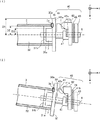
図2は本実施形態に係るベルト制御装置の断面概略図である。本実施形態のベルト制御装置は、図1における画像形成装置のテンションローラ52の少なくとも片側に設けられているため、図2はテンションローラ52の片側を拡大図で示している。図2(1)は、本実施形態のベルト制御装置の断面概略図である。図2(2)は図2(1)においてテンションローラ52、ローラ軸6、軸傾斜部41が傾斜している状態を表す図である。図3は図2(1)に示されるベルト制御装置の斜視図である。   FIG. 2 is a schematic cross-sectional view of the belt control device according to the present embodiment. Since the belt control device of this embodiment is provided on at least one side of the tension roller 52 of the image forming apparatus in FIG. 1, FIG. 2 shows one side of the tension roller 52 in an enlarged view. FIG. 2A is a schematic cross-sectional view of the belt control device of the present embodiment. FIG. 2 (2) is a diagram illustrating a state in which the tension roller 52, the roller shaft 6, and the shaft inclined portion 41 are inclined in FIG. 2 (1). FIG. 3 is a perspective view of the belt control device shown in FIG.

図2(1)に示されるように、ベルト制御装置はテンションローラ52の端部にテンションローラ52の軸と同軸であるローラ軸6を有している。ローラ軸6はテンションローラ52より直径が短い円柱の形状をしており、テンションローラ52と一体となっている。また、ローラ軸6は後述するベルト突当部30、ベルト位置補正部40をテンションローラ52の軸の方向(図2(1)に示されるz方向。以降、ローラ軸方向という)に貫通している。そのため、ローラ軸6はローラ軸方向に自由に動くことができ、ローラ軸方向と垂直な方向にはベルト突当部30、ベルト位置補正部40とともに動く。   As shown in FIG. 2 (1), the belt control device has a roller shaft 6 that is coaxial with the shaft of the tension roller 52 at the end of the tension roller 52. The roller shaft 6 has a cylindrical shape whose diameter is shorter than that of the tension roller 52 and is integrated with the tension roller 52. The roller shaft 6 passes through a belt abutting portion 30 and a belt position correcting portion 40, which will be described later, in the axial direction of the tension roller 52 (the z direction shown in FIG. 2 (1), hereinafter referred to as the roller axial direction). Yes. Therefore, the roller shaft 6 can freely move in the roller axis direction, and moves together with the belt abutting portion 30 and the belt position correcting portion 40 in a direction perpendicular to the roller axis direction.

テンションローラ52の端部に、ベルト突当部30がローラ軸方向に可動であるように設けられている。ベルト突当部30は、ローラ軸方向に対して略垂直な平面である平面部30aを有している。平面部30aの周縁は円を形成しており、その円の中心はテンションローラ52の軸上にある。また、平面部30aはベルト3がローラ軸方向外方に移動したときに、ベルト3の端部(ベルト端部3aという)が接するベルト端部当接部として機能する。   A belt abutting portion 30 is provided at the end of the tension roller 52 so as to be movable in the roller axial direction. The belt abutting portion 30 has a flat surface portion 30a that is a flat surface substantially perpendicular to the roller axial direction. The peripheral edge of the flat portion 30 a forms a circle, and the center of the circle is on the axis of the tension roller 52. Further, the flat surface portion 30a functions as a belt end contact portion that contacts an end portion of the belt 3 (referred to as a belt end portion 3a) when the belt 3 moves outward in the roller axis direction.

ベルト端部3aが移動して平面部30aに突き当たったときにベルト3がベルト突当部30に乗り上げてテンションローラ52から外れないように、図2(1)に示されるように平面部30aの周縁が形成する円の半径D1は、テンションローラ52の半径D2にベルト3の厚さを加えた長さより長く構成される。半径8.78(mm)のテンションローラ52、厚さ80(μm)のベルト3が用いられる場合、平面部30aの周縁の半径D1を8.86(mm)より長く、たとえば9.00(mm)とすればよい。   As shown in FIG. 2 (1), when the belt end portion 3a moves and hits the flat surface portion 30a, the belt 3 rides on the belt abutting portion 30 and does not come off the tension roller 52. The radius D1 of the circle formed by the peripheral edge is configured to be longer than the length obtained by adding the thickness of the belt 3 to the radius D2 of the tension roller 52. When the tension roller 52 having a radius of 8.78 (mm) and the belt 3 having a thickness of 80 (μm) are used, the radius D1 of the peripheral edge of the flat portion 30a is longer than 8.86 (mm), for example, 9.00 (mm )And it is sufficient.

なお、平面部30aはベルト端部当接部として機能するものであれば、その周縁が円でなく、たとえば長方形、多角形、その他任意の閉曲線を形成するものであってよい。その場合、テンションローラ52の軸からその長方形等の周縁までの距離D1は、テンションローラ52の半径D2にベルト3の厚さを加えた長さより長いものとする。また、平面部30aは凹凸や湾曲を有する面でもよく、ベルト端部当接部として機能するものであればその形状を問わない。   In addition, as long as the plane part 30a functions as a belt edge part contact part, the periphery may not form a circle but may form a rectangle, a polygon, and other arbitrary closed curves, for example. In this case, the distance D1 from the axis of the tension roller 52 to the periphery of the rectangle or the like is longer than the length obtained by adding the thickness of the belt 3 to the radius D2 of the tension roller 52. Further, the flat surface portion 30a may be a surface having unevenness or curvature, and the shape thereof is not limited as long as it functions as a belt end contact portion.

また、ベルト突当部30はテンションローラ52、ローラ軸6に対して固定されず、図2(1)に示されるxy平面内でテンションローラ52の軸と同じ軸を中心として自由に回転するように設けられている。このため、ベルト3が平面部30aに接している状態で走行するときに、ベルト突当部30はベルト端部3aとの摩擦力によりベルト3の走行に応じて回転する。   Further, the belt abutting portion 30 is not fixed with respect to the tension roller 52 and the roller shaft 6, and freely rotates about the same axis as the axis of the tension roller 52 in the xy plane shown in FIG. Is provided. For this reason, when the belt 3 travels in contact with the flat surface portion 30a, the belt abutting portion 30 rotates according to the travel of the belt 3 by the frictional force with the belt end portion 3a.

テンションローラ52の端部とベルト突当部30の間には円柱の形状に構成されたベルト端部支持部7が設けられている。ベルト端部支持部7は、その軸をテンションローラ52の軸と同軸とし、その半径D3はテンションローラ52の半径D2より短いものとする。これによって、ベルト3とベルト端部支持部7の側面の間に隙間(以降、隙間部31aという)が設けられる。このベルト端部支持部7はベルト端部3aがベルト突当部30と離れて重力によって垂れ下がるのを防ぐためにベルト端部3aを支えるものである。なお、ベルト端部支持部7はベルト端部3aを支えるものであれば、その形状は円柱ではなく角柱、立方体、その他いずれの形状であってもよい。また、テンションローラ52とベルト端部支持部7との間には隙間(以降、隙間部31bという)が設けられている。   Between the end portion of the tension roller 52 and the belt abutment portion 30, a belt end support portion 7 configured in a cylindrical shape is provided. The belt end support portion 7 has its axis coaxial with the axis of the tension roller 52, and its radius D3 is shorter than the radius D2 of the tension roller 52. Thus, a gap (hereinafter referred to as a gap portion 31a) is provided between the belt 3 and the side surface of the belt end portion support portion 7. The belt end portion support portion 7 supports the belt end portion 3a in order to prevent the belt end portion 3a from being separated from the belt abutting portion 30 and hanging down due to gravity. In addition, as long as the belt edge part support part 7 supports the belt edge part 3a, the shape may be not only a cylinder but a prism, a cube, or any other shape. In addition, a gap (hereinafter referred to as a gap 31b) is provided between the tension roller 52 and the belt end support portion 7.

また、ベルト突当部30のローラ軸方向外方には、ベルト突当部30と接するように軸傾斜部41が設けられている。また、軸傾斜部41はベルト3の面と平行な面に対してローラ軸方向外方を下にして傾斜している平面である傾斜面41aをローラ軸方向外方に有している。図3に示されるように傾斜面41aは円柱の側面の一部を形成するための形状であることが好適である。後述する軸ガイド部42と接する部分の面積を減らすことによって傾斜面41aと軸ガイド部42との間に発生する摩擦力による磨耗を減らすためである。   A shaft inclined portion 41 is provided outside the belt abutting portion 30 in the roller axial direction so as to be in contact with the belt abutting portion 30. Further, the shaft inclined portion 41 has an inclined surface 41a that is a flat surface that is inclined with the outer side in the roller axis direction downward with respect to a surface parallel to the surface of the belt 3. As shown in FIG. 3, it is preferable that the inclined surface 41a has a shape for forming a part of the side surface of the cylinder. This is to reduce wear due to the frictional force generated between the inclined surface 41a and the shaft guide portion 42 by reducing the area of the portion in contact with the shaft guide portion 42 described later.

また、軸傾斜部41は傾斜面41aのローラ軸方向外方に軸傾斜止め部41bを有している。図3および図5(1)に示されるように軸傾斜止め部41bはローラ軸6を中心軸とした円柱の側面の一部により実現されている。また、軸傾斜止め部41bを実現する面は図5(2)に示されるようにローラ軸6と異なる軸を中心軸とした円柱の側面の一部でもよいし、図5(3)に示されるように平面であってもよい。ただし、図5(1)に示される面により軸傾斜止め部41bが実現される場合、図5(2)および(3)に示される場合に比べて、後述する軸ガイド部42と接する部分の面積が減り、軸傾斜止め部41bと軸ガイド部42との間に発生する摩擦力による磨耗を減らすことができる。   Further, the shaft inclined portion 41 has a shaft inclination stopping portion 41b outside the inclined surface 41a in the roller axial direction. As shown in FIG. 3 and FIG. 5 (1), the shaft tilt stopper 41 b is realized by a part of a side surface of a cylinder having the roller shaft 6 as a central axis. Further, as shown in FIG. 5 (2), the surface that realizes the shaft tilt stopper 41b may be a part of a side surface of a cylinder having an axis different from the roller shaft 6 as a central axis, as shown in FIG. 5 (3). It may be a flat surface. However, in the case where the shaft tilt stopper 41b is realized by the surface shown in FIG. 5 (1), compared with the case shown in FIGS. 5 (2) and 5 (3), the portion in contact with the shaft guide portion 42 to be described later. The area is reduced, and wear due to the frictional force generated between the shaft tilt stopper 41b and the shaft guide 42 can be reduced.

傾斜面41aおよび軸傾斜止め部41bの材質は、摩擦係数が低く、耐摩耗性が高いポリアセタールが好適である。また、ローラ軸6と傾斜面41aのなす角度は30度程度が好適である。ベルト端部3aが突き当たったときに傾斜面41aが軸傾斜部当接部42aに加える負荷を少なくするためにローラ軸6と傾斜面41aのなす角度が小さい方がよく、一方、ローラ軸6と傾斜面41aのなす角度が小さすぎるとローラ軸6を傾けるために必要な軸傾斜部41の移動が大きくなり、軸傾斜部41が軸方向に移動するスペースを設けるために装置全体が大きくなってしまうからである。   The material of the inclined surface 41a and the shaft inclination stopper 41b is preferably polyacetal having a low friction coefficient and high wear resistance. The angle formed by the roller shaft 6 and the inclined surface 41a is preferably about 30 degrees. In order to reduce the load applied by the inclined surface 41a to the shaft inclined portion abutting portion 42a when the belt end 3a abuts, the angle formed between the roller shaft 6 and the inclined surface 41a is preferably small. If the angle formed by the inclined surface 41a is too small, the movement of the shaft inclined portion 41 necessary for inclining the roller shaft 6 increases, and the entire apparatus becomes larger in order to provide a space for the shaft inclined portion 41 to move in the axial direction. Because it ends up.

さらに、図2(1)に示されるように軸傾斜部41の軸方向外方に軸ガイド部42が設けられている。軸ガイド部42は、その一部である軸傾斜部当接部42aで傾斜面41aに接している。また、軸ガイド部42は軸傾斜部41に伴って移動しないように設けられている。このような構成によって、軸傾斜部41がローラ軸方向外方へ移動すると、図2(2)に示されるように軸傾斜部当接部42aが接する傾斜面41aの位置が上方にずれ、軸傾斜部41および軸傾斜部41を貫通しているローラ軸6が傾斜する。ローラ軸6が傾斜すると、一体となっているテンションローラ52が同様に傾斜する。また、軸傾斜部当接部42aはxz平面を断面としてみたときに円弧となる円柱の側面の一部であること(以降、R形状という)が好適である。この場合、xz平面を断面としてみたときに角状となっている場合に比べて軸傾斜部当接部42aが接する部分の傾斜面41aの磨耗が軽減される。   Further, as shown in FIG. 2 (1), a shaft guide portion 42 is provided on the axially outer side of the shaft inclined portion 41. The shaft guide portion 42 is in contact with the inclined surface 41a at a shaft inclined portion abutting portion 42a which is a part thereof. Further, the shaft guide portion 42 is provided so as not to move with the shaft inclined portion 41. With such a configuration, when the shaft inclined portion 41 moves outward in the roller axial direction, the position of the inclined surface 41a with which the shaft inclined portion abutting portion 42a contacts is shifted upward as shown in FIG. The roller shaft 6 passing through the inclined portion 41 and the shaft inclined portion 41 is inclined. When the roller shaft 6 is inclined, the integrated tension roller 52 is similarly inclined. Further, it is preferable that the shaft inclined portion abutting portion 42a is a part of a side surface of a cylinder that becomes an arc when the xz plane is taken as a cross section (hereinafter referred to as an R shape). In this case, the wear of the inclined surface 41a at the portion with which the shaft inclined portion abutting portion 42a contacts is reduced as compared with the case where the xz plane is seen as a cross section when the xz plane is viewed as a cross section.

また、ベルト制御装置が設置されたとき等、ベルト端部3aによるローラ軸方向の力が加えられていないとき、軸ガイド部42は軸傾斜部41の軸傾斜止め部41bに突き当たるため、軸傾斜部41は−x軸方向にずれることができない。さらに、テンションローラ52の他端に設けられている軸傾斜部41も同様に−x軸方向にずれることができない。このため、テンションローラ52は図2に示されるz軸にほぼ平行な状態となる位置(所定の位置)で設置される安定する。なお、x軸、z軸はローラ軸6がz軸に平行でずれていない場合における、それぞれベルト3の表面に垂直な方向、ローラ軸6の方向である。   In addition, when the belt end device 3a is not applied with a force in the roller axial direction, such as when a belt control device is installed, the shaft guide portion 42 abuts against the shaft tilt stopper 41b of the shaft tilt portion 41. The portion 41 cannot shift in the −x axis direction. Further, the shaft inclined portion 41 provided at the other end of the tension roller 52 cannot be shifted in the −x axis direction as well. For this reason, the tension roller 52 is stably installed at a position (predetermined position) that is substantially parallel to the z-axis shown in FIG. The x axis and the z axis are the direction perpendicular to the surface of the belt 3 and the direction of the roller shaft 6 when the roller shaft 6 is parallel to the z axis and not displaced.

一方、画像形成装置が動作し始めると、支持ローラ53,テンションローラ52が互いにほぼ平行な状態でない場合、ベルト3はローラ軸方向へ移動する。ベルト3がローラ軸方向へ移動しベルト突当部30に突き当たると、上述したように軸傾斜部41が傾斜するとともにローラ5が傾斜し、ベルト3が元の位置に戻る。この際、テンションローラ52がz軸にほぼ平行な状態となる所定の位置に設置されていると、このベルト3が元の位置に戻るまでの時間が短くなる。それは、支持ローラ52は製造時にはz軸方向に平行になるよう製造されるからである。つまり、軸傾斜部41を所定位置に決められないと、ローラ52は傾けて設置されてしまうこともありえ、その場合、他方のローラ53とほぼ平行な状態を維持できなくなる。そのため、ベルト3がz軸方向に大きく移動してしまい、ベルトが元の位置に戻り安定するまで多大な時間を要することになってしまう。この間に画像がベルト上に作られると各感光体からの転写像がずれて転写され色ヅレのような不具合が発生してしまう。   On the other hand, when the image forming apparatus starts to operate, if the support roller 53 and the tension roller 52 are not substantially parallel to each other, the belt 3 moves in the roller axis direction. When the belt 3 moves in the roller axial direction and abuts against the belt abutting portion 30, the shaft inclined portion 41 is inclined and the roller 5 is inclined as described above, and the belt 3 returns to the original position. At this time, if the tension roller 52 is installed at a predetermined position that is substantially parallel to the z-axis, the time until the belt 3 returns to the original position is shortened. This is because the support roller 52 is manufactured to be parallel to the z-axis direction at the time of manufacture. In other words, if the shaft inclined portion 41 cannot be determined at a predetermined position, the roller 52 may be inclined and installed, and in this case, it becomes impossible to maintain a state substantially parallel to the other roller 53. For this reason, the belt 3 moves greatly in the z-axis direction, and it takes a long time until the belt returns to its original position and is stabilized. If an image is formed on the belt during this time, the transferred image from each photoconductor is shifted and transferred, causing problems such as color fading.

ここで、軸傾斜部41の他の例について説明する。図4は軸傾斜部41の他の例を表す図である。ここで表されている軸傾斜部41においては軸傾斜止め部41bのみが図2(1)に示されるものと異なっている。上述において、軸傾斜止め部41bは図3に示されるようにローラ軸6を中心軸とした円柱の側面の一部により実現されるとしたが、図4に示されるようにローラ軸6と軸傾斜止め部41bを実現する円柱の側面は角度βをなしていてもよい。この場合、角度βが、ローラ軸6と傾斜面41aを実現する円柱側面のなす角度αより小さい所定の角度であればよい。このように軸傾斜止め部41が設けられる場合、軸傾斜止め部41bが設けられない場合に比べて、テンションローラ52および支持ローラ53が互いに平行な状態で安定しやすくなる。   Here, another example of the shaft inclined portion 41 will be described. FIG. 4 is a diagram illustrating another example of the shaft inclined portion 41. In the shaft inclined portion 41 shown here, only the shaft inclined stopping portion 41b is different from that shown in FIG. In the above description, the shaft tilt stopping portion 41b is realized by a part of the side surface of the cylinder having the roller shaft 6 as the central axis as shown in FIG. 3, but the roller shaft 6 and the shaft as shown in FIG. The side surface of the cylinder that realizes the tilt stopper 41b may form an angle β. In this case, the angle β may be a predetermined angle smaller than the angle α formed between the roller shaft 6 and the cylindrical side surface that realizes the inclined surface 41a. In this way, when the shaft tilt stopper 41 is provided, the tension roller 52 and the support roller 53 are more likely to be stable in a state parallel to each other, compared to when the shaft tilt stopper 41b is not provided.

また、軸ガイド部42のローラ軸方向外方に固定部46が設けられ、固定部46のローラ軸方向外方にローラ軸支持部43が設けられている。ここで、ローラ軸支持部43、固定部46の詳細について図6を用いて説明する。図6は、ローラ軸支持部43を表す図である。   Further, a fixed portion 46 is provided on the outer side of the shaft guide portion 42 in the roller axis direction, and a roller shaft support portion 43 is provided on the outer side of the fixed portion 46 in the roller axis direction. Here, details of the roller shaft support portion 43 and the fixed portion 46 will be described with reference to FIG. FIG. 6 is a diagram illustrating the roller shaft support portion 43.

図6に示されるようにローラ軸支持部43は、支持中心部43a、テンションローラ調整部43b、ベルト張架バネ43c、支持部本体43dを有している。
支持部本体43dはローラ軸方向外方を下にしてローラ軸6が傾斜するのに伴って、支持中心部43aを中心とした円弧に沿って図6に示される矢印アの方向へ傾斜する。また、支持部本体43dはローラ軸6の移動に伴って動くことのない固定部46とローラ軸支持バネ45によって連結されている。上述のように、支持部本体43dが矢印アで示される方向に傾斜するとローラ軸支持バネ45が伸びる。ローラ軸支持バネ45が伸びると、その伸びを戻す方向へ弾性力が発生しローラ軸支持部43は矢印イで示される方向へ戻ろうとする。なお、ローラ軸支持バネ45は弾性体の一例であり、バネに代えて板バネ、ゴム等によって実現されてもよい。
As shown in FIG. 6, the roller shaft support portion 43 has a support center portion 43a, a tension roller adjustment portion 43b, a belt tension spring 43c, and a support portion main body 43d.
The support portion main body 43d is inclined in the direction of arrow A shown in FIG. 6 along an arc centered on the support center portion 43a as the roller shaft 6 is inclined downward in the roller axial direction. Further, the support portion main body 43 d is connected by a fixed portion 46 that does not move with the movement of the roller shaft 6 and a roller shaft support spring 45. As described above, when the support portion main body 43d is inclined in the direction indicated by the arrow A, the roller shaft support spring 45 extends. When the roller shaft support spring 45 extends, an elastic force is generated in a direction to return the extension, and the roller shaft support portion 43 attempts to return in the direction indicated by the arrow A. The roller shaft support spring 45 is an example of an elastic body, and may be realized by a leaf spring, rubber, or the like instead of the spring.

テンションローラ調整部43bはローラ軸6を覆って接合されており、支持部本体43dとベルト張架バネ43cによって連結されている。ベルト張架バネ43cはテンションローラ調整部43b、ローラ軸6を通してテンションローラ52に対して他のローラから離れる方向に弾性力を加える。これによって、テンションローラ52に架け渡されたベルト3は弛むことなく張り詰めた状態を維持できる。なお、ベルト張架バネ43cはベルト張架用弾性体の一例であり、バネに代えて板バネ、ゴム等によって実現されてもよい。   The tension roller adjusting portion 43b is joined so as to cover the roller shaft 6, and is connected to the support portion main body 43d by a belt tension spring 43c. The belt tension spring 43c applies an elastic force in a direction away from the other rollers to the tension roller 52 through the tension roller adjusting portion 43b and the roller shaft 6. As a result, the belt 3 stretched around the tension roller 52 can be maintained in a tight state without being slackened. The belt tension spring 43c is an example of an elastic body for belt tension, and may be realized by a plate spring, rubber or the like instead of the spring.

また、ベルト制御装置には軸傾斜部41の回転を止める軸傾斜部回転止め部47が設けられている。軸傾斜部回転止め部47について図5および図7を用いて詳細に説明する。図5は、本実施形態に係る軸傾斜部および軸傾斜部回転止め部を表す断面図である。軸傾斜部回転止め部47は図5(1)に示されるように軸傾斜部41の側面と底面に沿って軸傾斜部41を覆う形状をしている。また、軸傾斜部回転止め部47はxy平面内で動くことができないように、固定して設けられている軸ガイド部42と接合されている。このため、軸傾斜部41がxy平面内で図5(1)の矢印ウの方向に回転するような力が加わっても軸傾斜部41は回転しない。一方、軸傾斜部回転止め部47軸傾斜部41がz方向に動くことを妨げるものではない。   Further, the belt control device is provided with a shaft inclined portion rotation stopping portion 47 that stops the rotation of the shaft inclined portion 41. The shaft inclined portion rotation stop portion 47 will be described in detail with reference to FIGS. 5 and 7. FIG. 5 is a cross-sectional view illustrating the shaft tilt portion and the shaft tilt portion rotation stopper according to the present embodiment. As shown in FIG. 5A, the shaft inclined portion rotation stopper 47 has a shape that covers the shaft inclined portion 41 along the side surface and the bottom surface of the shaft inclined portion 41. Further, the shaft inclined portion rotation stop portion 47 is joined to a shaft guide portion 42 that is fixedly provided so as not to move in the xy plane. For this reason, even if the force which rotates the axis | shaft inclination part 41 in the direction of arrow C of FIG. 5 (1) within xy plane is added, the axis | shaft inclination part 41 does not rotate. On the other hand, it does not prevent the shaft inclined portion rotation stopping portion 47 from moving in the z direction.

なお、軸傾斜部回転止め部47は軸傾斜部41の回転を止めるものであれば図5(1)に記載の形状でなくてもよい。図7は、軸傾斜部回転止め部47の他の例を説明するための図である。たとえば、軸傾斜部回転止め部47は図7(1)および(2)に示される形状であってもよい。また、軸傾斜部回転止め部47は図7(3)に示されるように軸傾斜部41と接合している部材であってもよい。または軸傾斜部41の一部が軸傾斜部回転止め部47として機能するとしてもよい。   As long as the shaft inclined portion rotation stopping portion 47 stops the rotation of the shaft inclined portion 41, it does not have to have the shape shown in FIG. FIG. 7 is a view for explaining another example of the shaft inclined portion rotation stopping portion 47. For example, the shaft inclined portion anti-rotation portion 47 may have the shape shown in FIGS. 7 (1) and (2). Further, the shaft inclined portion rotation stopper 47 may be a member joined to the shaft inclined portion 41 as shown in FIG. Alternatively, a part of the shaft inclined portion 41 may function as the shaft inclined portion rotation stop portion 47.

また、軸傾斜部回転止め部47は軸ガイド部42と接合されているものに限らず、ローラ軸の移動によって移動しない部材、たとえば固定部46や画像形成装置のフレームと接合してもよい。さらに、上述の実施形態ではベルト突当部30はベルト3の走行に応じて回転するものとされているが、ベルト突当部30が回転しないように設置されているものであれば、軸傾斜部回転止め部47はベルト突当部30と接合されてもよい。   Further, the shaft inclined portion rotation stop portion 47 is not limited to the one joined to the shaft guide portion 42, and may be joined to a member that does not move due to the movement of the roller shaft, for example, the fixed portion 46 or the frame of the image forming apparatus. Furthermore, in the above-described embodiment, the belt abutting portion 30 is rotated in accordance with the travel of the belt 3, but if the belt abutting portion 30 is installed so as not to rotate, the shaft inclination is inclined. The part rotation stopper 47 may be joined to the belt abutting part 30.

なお、上述した部材のうちテンションローラ52、ローラ軸6、ベルト突当部30、ベルト位置補正部40を有するものをローラユニットという。また、軸傾斜部41、軸ガイド部42、ローラ軸支持部43、固定部46、および図6に示されるローラ軸支持バネ45を有するものをベルト位置補正部40という。   A member having the tension roller 52, the roller shaft 6, the belt abutting portion 30, and the belt position correcting portion 40 among the members described above is referred to as a roller unit. Also, the belt position correction unit 40 includes the shaft inclined portion 41, the shaft guide portion 42, the roller shaft support portion 43, the fixing portion 46, and the roller shaft support spring 45 shown in FIG.

次に、本実施形態の画像形成装置におけるベルト制御装置の動作について説明する。画像形成装置の駆動ローラ51が駆動源によって回転すると、駆動ローラ51の回転に伴って図2(1)に示されるy方向(以降、走行方向という。)へベルト3が走行する。そして、ベルト3の走行に伴ってベルト3を架け渡しているテンションローラ52が回転する。このとき、ベルト3は、例えば複数のローラが互いに平行でないことが原因となってローラ軸方向へ移動することがある。ベルト3がローラ軸方向へ移動してベルト端部3aが平面部30aに突き当たると、ベルト端部3aがローラ軸方向外方への力をベルト突当部30に加えながら、ベルト3は走行方向へ走行する。   Next, the operation of the belt control device in the image forming apparatus of this embodiment will be described. When the driving roller 51 of the image forming apparatus is rotated by the driving source, the belt 3 travels in the y direction (hereinafter referred to as the traveling direction) shown in FIG. As the belt 3 travels, the tension roller 52 that spans the belt 3 rotates. At this time, the belt 3 may move in the roller axial direction because, for example, the plurality of rollers are not parallel to each other. When the belt 3 moves in the roller axial direction and the belt end portion 3a hits the flat surface portion 30a, the belt end 3a applies a force in the roller axial direction outward to the belt abutting portion 30, while the belt 3 moves in the running direction. Drive to.

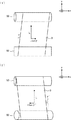
ここで、ベルト3におけるローラ軸方向の移動について図2および図8を用いて詳細に説明する。ここでは説明を容易にするためテンションローラ52および支持ローラ53に架け渡されている部分のベルト3の動作について説明する。   Here, the movement of the belt 3 in the roller axis direction will be described in detail with reference to FIGS. Here, for the sake of easy explanation, the operation of the belt 3 in the portion spanned between the tension roller 52 and the support roller 53 will be described.

図8は、ベルトのローラ軸方向への移動について説明するための図である。図8には、テンションローラ52および支持ローラ53にベルト3が架け渡され、テンションローラ52と支持ローラ53とが互いに平行でない状態が表されている。特に、図8(1)には、テンションローラ52が紙面に対して平行で、支持ローラ53の左側の端部が右側の端部よりx軸方向の紙面手前となるように傾いている状態が表されている。このようにテンションローラ52の軸と支持ローラ53の軸とが互いに平行でないことによって、ベルト3が走行方向に対して角度γで傾いている場合、ベルト3が距離Lだけ走行すると、ベルト3は+z方向(図8において右側に向かう方向)に距離Ltanγだけ移動する。   FIG. 8 is a diagram for explaining the movement of the belt in the roller axis direction. In FIG. 8, the belt 3 is stretched over the tension roller 52 and the support roller 53, and the tension roller 52 and the support roller 53 are not parallel to each other. In particular, FIG. 8A shows a state in which the tension roller 52 is parallel to the paper surface and the left end portion of the support roller 53 is tilted so as to be closer to the paper surface in the x-axis direction than the right end portion. It is represented. Thus, when the belt 3 is inclined at an angle γ with respect to the traveling direction because the shaft of the tension roller 52 and the shaft of the support roller 53 are not parallel to each other, when the belt 3 travels by the distance L, the belt 3 It moves by the distance Ltanγ in the + z direction (the direction toward the right side in FIG. 8).

ベルト3がローラ軸方向に移動してベルト突当部30に突き当たると、軸傾斜部41はローラ軸方向外方へ移動してローラ軸6およびテンションローラ52が傾斜する。この動作について具体的に説明する。   When the belt 3 moves in the roller axial direction and hits the belt abutting portion 30, the shaft inclined portion 41 moves outward in the roller axial direction, and the roller shaft 6 and the tension roller 52 are inclined. This operation will be specifically described.

図2(1)に示されるように、ベルト端部3aがベルト突当部30の平面部30aに突き当たるとベルト突当部30はローラ軸方向外方(+z方向)へ移動する。軸ベルト突当部30の移動によって軸傾斜部41にはローラ軸方向外方への力が加わる。この力によって軸傾斜部41がローラ軸方向外方へ移動すると、図2(2)に示されるように軸ガイド部42の軸傾斜部当接部42aが接する傾斜面41aの位置が上方にずれて傾斜する。そして、軸傾斜部41の傾斜に伴って軸傾斜部41を貫通しているローラ軸6の端部が+x方向(図2(2)において下側へ向かう方向)へ移動する。   As shown in FIG. 2A, when the belt end 3a hits the flat surface 30a of the belt abutting portion 30, the belt abutting portion 30 moves outward in the roller axis direction (+ z direction). By the movement of the shaft belt abutting portion 30, an outward force in the roller axial direction is applied to the shaft inclined portion 41. When the shaft inclined portion 41 is moved outward in the roller axial direction by this force, the position of the inclined surface 41a with which the shaft inclined portion abutting portion 42a of the shaft guide portion 42 contacts is shifted upward as shown in FIG. Tilt. As the shaft inclined portion 41 is inclined, the end portion of the roller shaft 6 that passes through the shaft inclined portion 41 moves in the + x direction (the direction toward the lower side in FIG. 2B).

ローラ軸6の端部が+x方向に移動すると、ローラ軸6が貫通しているテンションローラ52は傾斜する。図2(2)に示されるテンションローラ52が傾いた状態をx軸方向から見た図が図8(2)である。図8(2)に示されるようにテンションローラ52の左側の端部は右側の端部よりx軸方向の紙面手前となるよう傾斜している。ここで、テンションローラ52が支持ローラ53の傾斜より大きく傾斜していると、テンションローラ52および支持ローラ53は図8(1)に示される状態とは相対的に逆の傾きを形成することになる。テンションローラ52および支持ローラ53が相対的に逆の傾きを形成するとベルト3は−z方向(図8(2)において左側に向かう方向)に移動し元の位置に戻っていく。   When the end of the roller shaft 6 moves in the + x direction, the tension roller 52 through which the roller shaft 6 passes is inclined. FIG. 8 (2) shows a state in which the tension roller 52 shown in FIG. 2 (2) is tilted when viewed from the x-axis direction. As shown in FIG. 8B, the left end portion of the tension roller 52 is inclined so as to be in front of the right end portion in the x-axis direction. Here, when the tension roller 52 is inclined more than the inclination of the support roller 53, the tension roller 52 and the support roller 53 form an inclination that is relatively opposite to the state shown in FIG. Become. When the tension roller 52 and the support roller 53 form a relatively opposite inclination, the belt 3 moves in the −z direction (the direction toward the left side in FIG. 8B) and returns to the original position.

具体的には、図8(2)に示されるように、テンションローラ52が傾斜することによってベルト3の走行方向が角度γ’だけ傾斜した場合、ベルト3が距離Lだけ走行すると上述の動作と逆方向である−z方向へLtanγ’の距離だけ移動する。すなわち、テンションローラ52に架け渡されているベルト3は軸方向内方へ戻っていき、ベルト3の位置が元の位置に戻るように補正される。   Specifically, as shown in FIG. 8 (2), when the traveling direction of the belt 3 is inclined by the angle γ ′ due to the inclination of the tension roller 52, the operation described above is performed when the belt 3 travels by the distance L. It moves by a distance of Ltan γ ′ in the opposite direction, −z direction. That is, the belt 3 stretched around the tension roller 52 returns inward in the axial direction, and the position of the belt 3 is corrected so as to return to the original position.

また、上述の構成において、テンションローラ52とベルト端部支持部7との間には隙間部31bが設けられている(図2参照)ため、ガタが発生してテンションローラ52がローラ軸方向に動いてもテンションローラ52とベルト端部支持部7は離れている状態を維持する。そのためテンションローラ52がベルト端部支持部7を介してベルト突当部30および軸傾斜部41に対して軸方向外方へ力を加えることはない。したがって、ベルト端部3aがベルト突当部30に突き当たることによって加わる力のみによってローラ軸6は傾斜することができる。   Further, in the above-described configuration, since the gap 31b is provided between the tension roller 52 and the belt end support portion 7 (see FIG. 2), play occurs and the tension roller 52 moves in the roller axial direction. Even if it moves, the tension roller 52 and the belt end support portion 7 maintain a separated state. Therefore, the tension roller 52 does not apply a force outward in the axial direction to the belt abutting portion 30 and the shaft inclined portion 41 via the belt end support portion 7. Therefore, the roller shaft 6 can be tilted only by the force applied when the belt end 3 a hits the belt abutting portion 30.

すなわち、ベルト3がローラ軸方向外方に大きく移動した場合にはベルト端部3aがベルト突当部30に加わる力は大きく、そのためローラ軸6が傾斜する角度γ’が大きくなりベルト3がローラ軸方向内方へ戻っていく距離Ltanγ’が長くなる。一方、ベルト3のローラ軸方向外方への移動が小さい場合にはベルト端部3aがベルト突当部30に加える力は小さく、そのためローラ軸6が傾斜する角度γ’は小さくなりベルト3がローラ軸方向内方へ戻っていく距離Ltanγ’が短くなる。このようにベルト3のローラ軸方向外方への移動の大きさによって、ベルト3がローラ軸内方へ戻っていく距離が決まり、適切な補正が可能となる。   That is, when the belt 3 moves greatly outward in the roller axis direction, the force applied to the belt abutting portion 30 by the belt end portion 3a is large, so that the angle γ ′ at which the roller shaft 6 tilts increases and the belt 3 The distance Ltanγ ′ returning inward in the axial direction becomes longer. On the other hand, when the movement of the belt 3 outward in the roller axis direction is small, the force applied by the belt end 3a to the belt abutting portion 30 is small, so that the angle γ ′ at which the roller shaft 6 tilts becomes small and the belt 3 The distance Ltanγ ′ returning inward in the roller axial direction becomes shorter. Thus, the distance that the belt 3 returns to the inner side of the roller axis is determined by the magnitude of the movement of the belt 3 outward in the roller axis direction, and appropriate correction can be performed.

また、本実施形態においては、図6に示されるようにローラ軸支持バネ45が設けられているので、軸傾斜部41に対してローラ軸方向外方(z方向)への力が加わってローラ軸6の端部がx軸方向に移動すると、ローラ軸支持部43は図6の矢印アで示される方向に支持中心部43aを中心とした円弧に沿って傾斜する。ローラ軸支持部43が傾斜することによって伸びたローラ軸支持バネ45の伸びを戻す方向に弾性力が発生する。この弾性力によってローラ軸支持部43は元の位置の方(矢印イで示す方向)に戻ろうとするため、ローラ軸支持部43に覆われているローラ軸6は上方に変位しようとする。このため、軸傾斜部41は自重によって軸ガイド部42から離れることなく、傾斜面41aにおいて軸ガイド部42の軸傾斜部当接部42aと接した状態を保持することが可能となる。   Further, in the present embodiment, as shown in FIG. 6, the roller shaft support spring 45 is provided, so that a force is applied to the shaft inclined portion 41 outward in the roller axis direction (z direction). When the end portion of the shaft 6 moves in the x-axis direction, the roller shaft support portion 43 is inclined along an arc centered on the support center portion 43a in the direction indicated by the arrow A in FIG. An elastic force is generated in a direction to return the extension of the roller shaft support spring 45 extended by the inclination of the roller shaft support portion 43. Due to this elastic force, the roller shaft support portion 43 tends to return to the original position (the direction indicated by the arrow A), so that the roller shaft 6 covered by the roller shaft support portion 43 tends to be displaced upward. For this reason, the shaft inclined portion 41 can maintain a state in which the inclined surface 41a is in contact with the shaft inclined portion abutting portion 42a of the shaft guide portion 42 without being separated from the shaft guide portion 42 by its own weight.

ところで、上述のようにテンションローラ52が回転すると、これと接合して設けられているローラ軸6が回転する。このため、軸傾斜部41がローラ軸6との接触によって発生する摩擦力によって回転することがある。また、軸傾斜部41は上述のとおり回転するベルト突当部30との接触によって発生する摩擦力によって回転することがある。   By the way, when the tension roller 52 rotates as described above, the roller shaft 6 provided in contact with the tension roller 52 rotates. For this reason, the shaft inclined portion 41 may rotate due to a frictional force generated by contact with the roller shaft 6. Further, the shaft inclined portion 41 may be rotated by the frictional force generated by the contact with the belt abutting portion 30 that rotates as described above.

このように軸傾斜部41がローラ軸6の回転方向に回転すると軸傾斜部41の傾斜面41aが軸傾斜部当接部42aに接触しながら動くため、軸傾斜部41が回転しない場合に比べて磨耗が激しくなってしまう。そのため軸傾斜部回転止め部47を設けて、軸傾斜部41がxy平面内で図5の矢印ウの方向に回転するような摩擦力が加わっても軸傾斜部回転止め部47にあたって軸傾斜部41の回転が止まる。   As described above, when the shaft inclined portion 41 rotates in the rotation direction of the roller shaft 6, the inclined surface 41a of the shaft inclined portion 41 moves while contacting the shaft inclined portion abutting portion 42a, so that the shaft inclined portion 41 does not rotate. Wear out. Therefore, the shaft inclined portion rotation stopper 47 is provided, and even if a frictional force is applied to the shaft inclined portion 41 in the direction of arrow C in FIG. The rotation of 41 stops.

以上のように本実施形態において軸傾斜部回転止め部47を設けることによって、ローラ軸6の回転に伴って軸傾斜部41が回転するのを防ぐことができ、軸傾斜部41と軸ガイド部42における接点での磨耗を減少することが可能となる。したがって、軸傾斜部41や軸ガイド部42の損傷を防ぐことができるので、ベルト3の搬送における不具合を減少したり、部品の寿命を延ばしたりすることが可能となる。   As described above, in the present embodiment, by providing the shaft inclined portion rotation stop portion 47, the shaft inclined portion 41 can be prevented from rotating with the rotation of the roller shaft 6, and the shaft inclined portion 41 and the shaft guide portion can be prevented. It is possible to reduce wear at the contacts at 42. Therefore, the shaft inclined portion 41 and the shaft guide portion 42 can be prevented from being damaged, so that problems in conveying the belt 3 can be reduced and the life of components can be extended.

ここで、上述のように動作する画像形成装置においてベルト制御装置が設置される状態について図9を用いて説明する。図9は、ローラおよびベルト制御装置を設置した状態を表す図である。既に説明したとおり、軸傾斜部41は軸傾斜部当接部42aと接しながらx軸方向に移動するため、軸傾斜止め部41bを有しない構成の場合、図9(2)に示されるようにローラ軸6がz軸に平行とならない状態で設置されてしまうことがある。   Here, a state in which the belt control device is installed in the image forming apparatus operating as described above will be described with reference to FIG. FIG. 9 is a diagram illustrating a state in which the roller and the belt control device are installed. As already described, since the shaft inclined portion 41 moves in the x-axis direction while contacting the shaft inclined portion abutting portion 42a, as shown in FIG. 9 (2) in the case of the configuration without the shaft inclined stopping portion 41b. The roller shaft 6 may be installed without being parallel to the z-axis.

このような構成において、図9(1)に示されるようにテンションローラ52の一の端部に設けられている軸傾斜部41が軸傾斜止め部41bを有し、ローラの他の端部に設けられている軸傾斜部41’が軸傾斜止め部41b’を有することによって、ローラ軸6はz軸に平行な状態で安定する。具体的には、ベルト制御装置が設置されるとき画像形成装置は動作していないため軸傾斜部41、軸傾斜部41’ともにz軸方向への力を受けることはない。そのような状態でベルト制御装置が設置されると、軸傾斜止め部41bが軸ガイド部42のR形状を形成する下面と突き当たって軸傾斜部41の−x軸方向への移動が妨げられる。このため軸傾斜止め部41b’も+x軸方向へ移動しない。同様に、軸傾斜部41’の軸傾斜止め部41b’が軸ガイド部42’のR形状の下面と突き当たって軸傾斜部41’の−x軸方向への移動が妨げられる。このため軸傾斜止め部41bも+x軸方向へ移動しない。   In such a configuration, as shown in FIG. 9 (1), the shaft inclined portion 41 provided at one end portion of the tension roller 52 has the shaft inclination stopping portion 41b, and the other end portion of the roller is provided with the shaft inclined stop portion 41b. Since the provided shaft inclined portion 41 ′ has the shaft inclination stopper 41 b ′, the roller shaft 6 is stabilized in a state parallel to the z axis. Specifically, since the image forming apparatus is not operating when the belt control device is installed, neither the shaft inclined portion 41 nor the shaft inclined portion 41 ′ receives a force in the z-axis direction. When the belt control device is installed in such a state, the shaft tilt stopper 41b abuts against the lower surface of the shaft guide portion 42 forming the R shape, and the shaft tilt portion 41 is prevented from moving in the -x-axis direction. For this reason, the shaft tilt stopper 41b 'does not move in the + x-axis direction. Similarly, the shaft tilt stop portion 41b 'of the shaft tilt portion 41' abuts against the R-shaped lower surface of the shaft guide portion 42 ', thereby preventing the shaft tilt portion 41' from moving in the -x-axis direction. For this reason, the shaft tilt stopper 41b does not move in the + x-axis direction.

これらの結果、軸ガイド部42、軸ガイド部42’のR形状の下面が、それぞれ軸傾斜止め部41b、軸傾斜止め部41b’と接する位置で安定し、ローラ軸6、ローラ軸6’、およびそれらと一体となっているテンションローラ52はz軸に平行な状態で安定する。同様にして、支持ローラ53もz軸に平行な状態で安定するため、テンションローラ52と支持ローラ53は互いに平行な状態で安定する。なお、画像形成装置が動作し、軸傾斜部41または軸傾斜部41’にz軸方向の力が加わると上述したようにローラ軸6、ローラ軸6’、テンションローラ52は図9(3)に示されるように傾斜する。   As a result, the R-shaped lower surfaces of the shaft guide portion 42 and the shaft guide portion 42 ′ are stabilized at the positions in contact with the shaft tilt stopper portion 41b and the shaft tilt stopper portion 41b ′, respectively, and the roller shaft 6, the roller shaft 6 ′, The tension roller 52 integrated with them is stable in a state parallel to the z-axis. Similarly, since the support roller 53 is stabilized in a state parallel to the z axis, the tension roller 52 and the support roller 53 are stabilized in a state parallel to each other. When the image forming apparatus is operated and a force in the z-axis direction is applied to the shaft inclined portion 41 or the shaft inclined portion 41 ′, the roller shaft 6, the roller shaft 6 ′, and the tension roller 52 are as shown in FIG. Tilt as shown.

このように、互いに隣接するローラのそれぞれの軸傾斜部41に軸傾斜止め部41bを設けることによって画像形成装置が動作し始めるとき、複数のローラ軸が平行でないことに起因するベルト3のローラ軸方向への移動を防ぐことができる。また、軸傾斜止め部41bを設けて複数のローラ軸が平行な状態(図9(2)参照)となるようにした場合、複数のローラが互いに平行でない状態(図9(1)参照)場合に比べて、ベルト3のローラ軸方向の移動を補正するときに軸傾斜部41およびローラ軸6が傾斜する状態(図9(3)参照)までのローラの移動量は小さいもので済む。移動量が大きくなる場合に比べ、短時間でベルト3の走行方向を補正することができ、補正されるまでに発生する画像の不良を減少させることが可能となる。   In this way, when the image forming apparatus starts to operate by providing the shaft tilt stoppers 41b in the shaft tilt portions 41 of the rollers adjacent to each other, the roller shafts of the belt 3 caused by the plurality of roller shafts not being parallel. Movement in the direction can be prevented. Also, when the shaft tilt stopper 41b is provided so that the plurality of roller shafts are in a parallel state (see FIG. 9 (2)), the plurality of rollers are not parallel to each other (see FIG. 9 (1)). In comparison with the above, when the movement of the belt 3 in the roller axis direction is corrected, the amount of movement of the roller until the shaft inclined portion 41 and the roller shaft 6 are inclined (see FIG. 9 (3)) is small. Compared with the case where the amount of movement becomes large, the traveling direction of the belt 3 can be corrected in a short time, and it is possible to reduce image defects occurring before the correction.

なお、本実施形態においては、テンションローラ52に隣接するローラである支持ローラ53においても同様の構成のベルト制御装置を設けることによって、支持ローラ53もz軸に平行な状態で安定する。このようにして、テンションローラ52と支持ローラ53を互いに平行な状態とし安定させてもよい。   In the present embodiment, the support roller 53 which is a roller adjacent to the tension roller 52 is also provided with a belt control device having the same configuration, so that the support roller 53 is also stabilized in a state parallel to the z axis. In this way, the tension roller 52 and the support roller 53 may be parallel to each other and stabilized.

また、テンションローラ52でないローラ、すなわち駆動ローラ51、支持ローラ53、支持ローラ54に係るベルトユニットにおいてはベルトのテンションを維持する機能を有しないためテンションローラ調整部43b、ベルト張架バネ43cは必要がない。したがって、駆動ローラ51、支持ローラ53、支持ローラ54においては、軸傾斜部回転止め部47が軸ガイド部42と接合して設けられればよい。   Further, since the belt unit related to the rollers other than the tension roller 52, that is, the driving roller 51, the support roller 53, and the support roller 54 does not have a function of maintaining the belt tension, the tension roller adjusting portion 43b and the belt tension spring 43c are necessary. There is no. Therefore, in the driving roller 51, the support roller 53, and the support roller 54, it is only necessary that the shaft inclined portion rotation prevention portion 47 is provided so as to be joined to the shaft guide portion 42.

また、テンションローラ52に限らず、駆動ローラ51,テンションローラ52、支持ローラ53、支持ローラ54のいずれか二以上のローラの端部にベルト制御装置が設けられてもよい。   In addition to the tension roller 52, a belt control device may be provided at the end of any two or more of the drive roller 51, the tension roller 52, the support roller 53, and the support roller 54.

また、本実施形態において、軸傾斜部41はローラ軸方向外方にベルトの面と平行な面に対してローラ軸方向外方を下にして傾斜している平面である傾斜面41aをテンションローラ52の軸より上側に有しているとしたが、ローラ軸方向外方にベルトの面と平行な面に対してローラ軸方向外方を上にして傾斜している平面である傾斜面41aをテンションローラ52の軸より下側に有しているとしてもよい。   Further, in the present embodiment, the shaft inclined portion 41 has an inclined surface 41a that is a flat surface inclined outwardly in the roller axial direction with respect to a surface parallel to the surface of the belt outward in the roller axial direction. The inclined surface 41a is a flat surface that is inclined outwardly in the roller axial direction with respect to a surface parallel to the surface of the belt outward in the roller axial direction. It may be provided below the axis of the tension roller 52.

また、本実施形態において、軸傾斜部41はベルト端部3aが平面部30aに接した状態でベルトが走行方向へ走行すると、ベルト端部3aと平面部30aの間で発生する摩擦力によってベルト突当部30はベルト3の走行に応じて回転する。これによって、ベルト端部3aが摩擦力によって受ける負荷を低減でき、ベルト3の破損、平面部30aの磨耗を防止することが可能となる。   Further, in the present embodiment, the shaft inclined portion 41 is formed by the frictional force generated between the belt end portion 3a and the flat surface portion 30a when the belt travels in the traveling direction with the belt end portion 3a being in contact with the flat surface portion 30a. The abutting portion 30 rotates according to the travel of the belt 3. As a result, the load applied to the belt end 3a by the frictional force can be reduced, and the belt 3 can be prevented from being damaged and the flat portion 30a being worn.

1 感光体
3 中間転写ベルト
6 ローラ軸
7 ベルト端部支持部
8 帯電部
9 露光部
10 現像部
11 転写ローラ
12 クリーニング部
14 給紙部
15 給紙ローラ
16 レジストローラ対
17 二次転写ローラ
18 定着部
19 排紙ローラ対
20 ベルトクリーニング部
21 クリーニングブレード
40 ベルト位置補正部
30 ベルト突当部
30a 平面部
41 軸傾斜部
41a 傾斜面
41b 軸傾斜止め部
42 軸ガイド部
42a 軸傾斜部当接部
43 ローラ軸支持部
43a 支持中心部
43b テンションローラ調整部
43c ベルト張架バネ
43d 支持部本体
45 ローラ軸支持バネ
46 固定部
47 軸傾斜部回転止め部
51 駆動ローラ
52 テンションローラ
53 支持ローラ
54 支持ローラ
DESCRIPTION OF SYMBOLS 1 Photoconductor 3 Intermediate transfer belt 6 Roller shaft 7 Belt end support part 8 Charging part 9 Exposure part 10 Development part 11 Transfer roller 12 Cleaning part 14 Paper feed part 15 Paper feed roller 16 Registration roller pair 17 Secondary transfer roller 18 Fixing Part 19 discharge roller pair 20 belt cleaning part 21 cleaning blade 40 belt position correction part 30 belt abutting part 30a flat part 41 shaft inclined part 41a inclined surface 41b shaft inclination stopping part 42 shaft guide part 42a shaft inclined part contact part 43 Roller shaft support portion 43a Support center portion 43b Tension roller adjustment portion 43c Belt tension spring 43d Support portion main body 45 Roller shaft support spring 46 Fixed portion 47 Shaft inclined portion rotation prevention portion 51 Drive roller 52 Tension roller 53 Support roller 54 Support roller

特開2009−288426号公報JP 2009-288426 A

Claims (8)

複数のローラに掛け渡されて前記複数のローラの回転とともに走行するベルトの、前記ローラの軸方向への移動を制御するベルト制御装置であって、
前記複数のローラのうち、少なくとも一のローラの両端部に、
前記少なくとも一のローラのローラ軸方向への前記ベルトの移動によって当該ローラの軸方向へ移動して当該ローラのローラ軸を傾斜させる軸傾斜部と、
該軸傾斜部の移動に伴って移動せず、前記軸傾斜部の前記傾斜面と接する軸傾斜部当接部を備えた軸ガイド部とを備え、
前記ベルトの移動によって前記軸傾斜部が当該ローラ軸方向へ移動すると、前記傾斜面に対する前記軸傾斜部当接部の当接位置が該傾斜面上を移動して、該軸傾斜部が当該ローラ軸方向に対して直交する方向へ変位し、前記ベルトの移動を戻すように当該ローラのローラ軸が傾斜するように構成されており、
前記軸傾斜部は、前記傾斜面の当該ローラ軸方向外方に、前記軸ガイド部に突き当たって当該ローラ軸方向に対して直交する方向への当該軸傾斜部の変位を規制して前記少なくとも一のローラのローラ軸の傾斜を止める軸傾斜止め部を備えており、
前記ベルト制御装置が設置されたとき、前記ローラの両端部では、前記軸傾斜止め部によって前記少なくとも一のローラのローラ軸の傾斜が止められていることを特徴とするベルト制御装置
A belt control device for controlling movement of the belt in the axial direction of a belt, which is stretched around a plurality of rollers and travels with rotation of the plurality of rollers;
Among the plurality of rollers, the both end portions of at least one B over La,
A shaft inclined portion that moves in the axial direction of the roller by the movement of the belt in the roller axial direction of the at least one roller to incline the roller shaft of the roller ;
A shaft guide portion provided with a shaft inclined portion abutting portion that does not move along with the movement of the shaft inclined portion and is in contact with the inclined surface of the shaft inclined portion;
When the shaft inclined portion moves in the roller axial direction by the movement of the belt, the contact position of the shaft inclined portion abutting portion with respect to the inclined surface moves on the inclined surface, and the shaft inclined portion becomes the roller. The roller shaft of the roller is configured to be inclined so as to be displaced in a direction orthogonal to the axial direction and to return the movement of the belt.
The shaft inclined portion regulates displacement of the shaft inclined portion in a direction perpendicular to the roller axial direction by striking the shaft guide portion outward of the inclined surface in the roller axial direction, and the dew slope of over la roller shaft provided with a stop mel axis tilt preventing portion,
When the belt control device is installed, a tilt of the roller shaft of the at least one roller is stopped at both end portions of the roller by the shaft tilt stop portion .
求項1に記載のベルト制御装置であって、
前記軸傾斜部は、前記傾斜面の当該ローラ軸方向外方の端部に設けられ、前記軸ガイド部の前記軸傾斜部当接部が突き当たる所定の面を有し、当該所定の面前記ローラ軸となす角度は前記傾斜面と前記少なくとも一のローラのローラ軸がなす角度より小さいことを特徴とするベルト制御装置。
A belt control device according to Motomeko 1,
The shaft inclined portion is provided at an end of the roller shaft outwardly of the inclined surface has a predetermined surface on which the shaft inclined abutting part of the shaft guide part abuts, wherein the said predetermined surface angle between the roller axis, the belt control device, characterized in that said inclined surface the less than roller shaft and the angle of the at least one roller.
請求項2に記載のベルト制御装置であって、
前記所定の面は、円柱の側面の一部であることを特徴とするベルト制御装置。
The belt control device according to claim 2 ,
The belt control device according to claim 1, wherein the predetermined surface is a part of a side surface of a cylinder.
請求項3に記載のベルト制御装置であって、
前記円柱の軸は前記ローラ軸と同じであることを特徴とするベルト制御装置。
The belt control device according to claim 3 ,
The belt control device according to claim 1 , wherein an axis of the cylinder is the same as the roller axis.
請求項1乃4のいずれか一項に記載のベルト制御装置であって、
前記軸傾斜部当接部の前記傾斜面と接する部分は円柱の側面の一部であることを特徴とするベルト制御装置
A belt control device according to any one of claims 1乃 Itaru 4,
The belt controller according to claim 1 , wherein a portion of the shaft inclined portion contact portion that contacts the inclined surface is a part of a side surface of a cylinder .
無端状のベルトが懸架された複数のローラからなるローラユニットであって、
当該ベルトの、前記複数のローラのうち少なくとも一のローラのローラ軸方向への移動を制御するベルト制御装置を備え、
前記複数のローラのうち、少なくとも一のローラの両端部に、
前記少なくとも一のローラのローラ軸方向への前記ベルトの移動によって当該ローラの軸方向へ移動して当該ローラのローラ軸を傾斜させる軸傾斜部と、
該軸傾斜部の移動に伴って移動せず、前記軸傾斜部の前記傾斜面と接する軸傾斜部当接部を備えた軸ガイド部とを備え、
前記ベルトの移動によって前記軸傾斜部が当該ローラ軸方向へ移動すると、前記傾斜面に対する前記軸傾斜部当接部の当接位置が該傾斜面上を移動して、該軸傾斜部が当該ローラ軸方向に対して直交する方向へ変位し、前記ベルトの移動を戻すように当該ローラのローラ軸が傾斜するように構成されており、
前記軸傾斜部は、前記傾斜面の当該ローラ軸方向外方に、前記軸ガイド部に突き当たって当該ローラ軸方向に対して直交する方向への当該軸傾斜部の変位を規制して前記少なくとも一のローラのローラ軸の傾斜を止める軸傾斜止め部を備えており、
前記ベルト制御装置が設置されたとき、前記ローラの両端部では、前記軸傾斜止め部によって前記少なくとも一のローラのローラ軸の傾斜が止められていることを特徴とするローラユニット。
A roller unit composed of a plurality of rollers on which an endless belt is suspended ,
A belt control device for controlling movement of at least one of the plurality of rollers in the roller axial direction of the belt;
Among the plurality of rollers, the both end portions of at least one B over La,
A shaft inclined portion that moves in the axial direction of the roller by the movement of the belt in the roller axial direction of the at least one roller to incline the roller shaft of the roller ;
A shaft guide portion provided with a shaft inclined portion abutting portion that does not move along with the movement of the shaft inclined portion and is in contact with the inclined surface of the shaft inclined portion;
When the shaft inclined portion moves in the roller axial direction by the movement of the belt, the contact position of the shaft inclined portion abutting portion with respect to the inclined surface moves on the inclined surface, and the shaft inclined portion becomes the roller. The roller shaft of the roller is configured to be inclined so as to be displaced in a direction orthogonal to the axial direction and to return the movement of the belt.
The shaft inclined portion regulates displacement of the shaft inclined portion in a direction perpendicular to the roller axial direction by striking the shaft guide portion outward of the inclined surface in the roller axial direction, and the dew slope of over la roller shaft provided with a stop mel axis tilt preventing portion,
When the belt control device is installed , the roller unit is characterized in that an inclination of the roller shaft of the at least one roller is stopped by the shaft inclination stopping portion at both ends of the roller.
請求項1乃至5のいずれか一項に記載のベルト制御装置または請求項6に記載のローラユニットを有することを特徴とする画像形成装置。 An image forming apparatus, comprising a roller unit according to the belt control device or claim 6 according to any one of claims 1 to 5. 無端状のベルトが懸架された複数のローラのうちの2以上のローラに、請求項1乃至5のいずれか一項に記載のベルト制御装置を有することを特徴とする画像形成装置。An image forming apparatus comprising the belt control device according to any one of claims 1 to 5 on two or more of a plurality of rollers on which an endless belt is suspended.
JP2012245392A 2012-11-07 2012-11-07 Belt control device, roller unit, and image forming apparatus Active JP6048809B2 (en)

Priority Applications (1)

Application Number Priority Date Filing Date Title
JP2012245392A JP6048809B2 (en) 2012-11-07 2012-11-07 Belt control device, roller unit, and image forming apparatus

Applications Claiming Priority (1)

Application Number Priority Date Filing Date Title
JP2012245392A JP6048809B2 (en) 2012-11-07 2012-11-07 Belt control device, roller unit, and image forming apparatus

Publications (2)

Publication Number Publication Date
JP2014095737A JP2014095737A (en) 2014-05-22
JP6048809B2 true JP6048809B2 (en) 2016-12-21

Family

ID=50938864

Family Applications (1)

Application Number Title Priority Date Filing Date
JP2012245392A Active JP6048809B2 (en) 2012-11-07 2012-11-07 Belt control device, roller unit, and image forming apparatus

Country Status (1)

Country Link
JP (1) JP6048809B2 (en)

Families Citing this family (3)

* Cited by examiner, † Cited by third party
Publication number Priority date Publication date Assignee Title
JP6691682B2 (en) 2016-02-23 2020-05-13 株式会社リコー Belt control device, belt device, and image forming apparatus
US10955771B2 (en) 2019-03-18 2021-03-23 Ricoh Company, Ltd. Belt control device and image forming apparatus incorporating same
US11112734B2 (en) 2019-03-18 2021-09-07 Ricoh Company, Ltd. Belt device, belt regulator, roller unit, and image forming apparatus

Family Cites Families (3)

* Cited by examiner, † Cited by third party
Publication number Priority date Publication date Assignee Title
JP4260066B2 (en) * 2004-05-31 2009-04-30 株式会社リコー Belt conveying apparatus and image forming apparatus
JP2010002560A (en) * 2008-06-19 2010-01-07 Fuji Xerox Co Ltd Belt drive mechanism and image forming apparatus
JP2011008049A (en) * 2009-06-26 2011-01-13 Fuji Xerox Co Ltd Belt driving mechanism and image forming apparatus

Also Published As

Publication number Publication date
JP2014095737A (en) 2014-05-22

Similar Documents

Publication Publication Date Title
JP5761624B2 (en) Belt control device, roller unit, and image forming apparatus
JP6041215B2 (en) Belt control device, roller unit, and image forming apparatus
JP6344636B2 (en) Belt control device, roller unit, and image forming apparatus
JP6048791B2 (en) Belt control device, roller unit, and image forming apparatus
JP6016069B2 (en) Belt control device, roller unit, and image forming apparatus.
JP2013238823A (en) Belt controller, roller unit, and image forming apparatus
JP6452029B2 (en) Image forming apparatus
JP6319656B2 (en) Belt device and image forming apparatus having the same
JP2009186910A (en) Device for preventing belt skew and image forming apparatus provided with the same
JP6485730B2 (en) Recording material conveying apparatus and image forming apparatus
JP6691682B2 (en) Belt control device, belt device, and image forming apparatus
JP6963724B2 (en) Belt device and image forming device
JP6778414B2 (en) Belt device, transfer device and image forming device
JP6048809B2 (en) Belt control device, roller unit, and image forming apparatus
JP2013097263A (en) Image forming apparatus
JP6292474B2 (en) Belt device and image forming apparatus having the same
JP5266776B2 (en) Belt misalignment correction apparatus, belt apparatus, and image forming apparatus
JP6628141B2 (en) Belt device, transfer device, intermediate transfer device, and image forming device
JP2016200766A (en) Belt device, transfer device, and image forming apparatus
JP2013242384A (en) Belt control device, roller unit, and image forming apparatus
JP2017058651A (en) Belt control device, belt device, intermediate transfer device, transfer device, and image forming apparatus
JP5660101B2 (en) Belt device and image forming apparatus
JP7360621B2 (en) Belt device, transfer device, and image forming device
JP5979484B2 (en) Belt control device, roller unit, and image forming apparatus
JP2016156874A (en) Belt control apparatus and image forming apparatus

Legal Events

Date Code Title Description
A621 Written request for application examination

Free format text: JAPANESE INTERMEDIATE CODE: A621

Effective date: 20151015

A977 Report on retrieval

Free format text: JAPANESE INTERMEDIATE CODE: A971007

Effective date: 20160727

A131 Notification of reasons for refusal

Free format text: JAPANESE INTERMEDIATE CODE: A131

Effective date: 20160729

A521 Written amendment

Free format text: JAPANESE INTERMEDIATE CODE: A523

Effective date: 20160909

TRDD Decision of grant or rejection written
A01 Written decision to grant a patent or to grant a registration (utility model)

Free format text: JAPANESE INTERMEDIATE CODE: A01

Effective date: 20161028

A61 First payment of annual fees (during grant procedure)

Free format text: JAPANESE INTERMEDIATE CODE: A61

Effective date: 20161110

R151 Written notification of patent or utility model registration

Ref document number: 6048809

Country of ref document: JP

Free format text: JAPANESE INTERMEDIATE CODE: R151