JP4794281B2 - Belt drive device and image forming apparatus having the same - Google Patents
Belt drive device and image forming apparatus having the same Download PDFInfo
- Publication number
- JP4794281B2 JP4794281B2 JP2005330999A JP2005330999A JP4794281B2 JP 4794281 B2 JP4794281 B2 JP 4794281B2 JP 2005330999 A JP2005330999 A JP 2005330999A JP 2005330999 A JP2005330999 A JP 2005330999A JP 4794281 B2 JP4794281 B2 JP 4794281B2
- Authority
- JP
- Japan
- Prior art keywords
- roller
- belt
- endless belt
- cleaning
- disposed
- Prior art date
- Legal status (The legal status is an assumption and is not a legal conclusion. Google has not performed a legal analysis and makes no representation as to the accuracy of the status listed.)
- Active
Links
Images


Classifications
-
- G—PHYSICS
- G03—PHOTOGRAPHY; CINEMATOGRAPHY; ANALOGOUS TECHNIQUES USING WAVES OTHER THAN OPTICAL WAVES; ELECTROGRAPHY; HOLOGRAPHY
- G03G—ELECTROGRAPHY; ELECTROPHOTOGRAPHY; MAGNETOGRAPHY
- G03G15/00—Apparatus for electrographic processes using a charge pattern
- G03G15/75—Details relating to xerographic drum, band or plate, e.g. replacing, testing
-
- G—PHYSICS
- G03—PHOTOGRAPHY; CINEMATOGRAPHY; ANALOGOUS TECHNIQUES USING WAVES OTHER THAN OPTICAL WAVES; ELECTROGRAPHY; HOLOGRAPHY
- G03G—ELECTROGRAPHY; ELECTROPHOTOGRAPHY; MAGNETOGRAPHY
- G03G15/00—Apparatus for electrographic processes using a charge pattern
- G03G15/14—Apparatus for electrographic processes using a charge pattern for transferring a pattern to a second base
- G03G15/16—Apparatus for electrographic processes using a charge pattern for transferring a pattern to a second base of a toner pattern, e.g. a powder pattern, e.g. magnetic transfer
- G03G15/1605—Apparatus for electrographic processes using a charge pattern for transferring a pattern to a second base of a toner pattern, e.g. a powder pattern, e.g. magnetic transfer using at least one intermediate support
- G03G15/161—Apparatus for electrographic processes using a charge pattern for transferring a pattern to a second base of a toner pattern, e.g. a powder pattern, e.g. magnetic transfer using at least one intermediate support with means for handling the intermediate support, e.g. heating, cleaning, coating with a transfer agent
-
- G—PHYSICS
- G03—PHOTOGRAPHY; CINEMATOGRAPHY; ANALOGOUS TECHNIQUES USING WAVES OTHER THAN OPTICAL WAVES; ELECTROGRAPHY; HOLOGRAPHY
- G03G—ELECTROGRAPHY; ELECTROPHOTOGRAPHY; MAGNETOGRAPHY
- G03G15/00—Apparatus for electrographic processes using a charge pattern
- G03G15/14—Apparatus for electrographic processes using a charge pattern for transferring a pattern to a second base
- G03G15/16—Apparatus for electrographic processes using a charge pattern for transferring a pattern to a second base of a toner pattern, e.g. a powder pattern, e.g. magnetic transfer
- G03G15/1665—Apparatus for electrographic processes using a charge pattern for transferring a pattern to a second base of a toner pattern, e.g. a powder pattern, e.g. magnetic transfer by introducing the second base in the nip formed by the recording member and at least one transfer member, e.g. in combination with bias or heat
- G03G15/167—Apparatus for electrographic processes using a charge pattern for transferring a pattern to a second base of a toner pattern, e.g. a powder pattern, e.g. magnetic transfer by introducing the second base in the nip formed by the recording member and at least one transfer member, e.g. in combination with bias or heat at least one of the recording member or the transfer member being rotatable during the transfer
- G03G15/168—Apparatus for electrographic processes using a charge pattern for transferring a pattern to a second base of a toner pattern, e.g. a powder pattern, e.g. magnetic transfer by introducing the second base in the nip formed by the recording member and at least one transfer member, e.g. in combination with bias or heat at least one of the recording member or the transfer member being rotatable during the transfer with means for conditioning the transfer element, e.g. cleaning
-
- G—PHYSICS
- G03—PHOTOGRAPHY; CINEMATOGRAPHY; ANALOGOUS TECHNIQUES USING WAVES OTHER THAN OPTICAL WAVES; ELECTROGRAPHY; HOLOGRAPHY
- G03G—ELECTROGRAPHY; ELECTROPHOTOGRAPHY; MAGNETOGRAPHY
- G03G15/00—Apparatus for electrographic processes using a charge pattern
- G03G15/65—Apparatus which relate to the handling of copy material
- G03G15/6529—Transporting
-
- G—PHYSICS
- G03—PHOTOGRAPHY; CINEMATOGRAPHY; ANALOGOUS TECHNIQUES USING WAVES OTHER THAN OPTICAL WAVES; ELECTROGRAPHY; HOLOGRAPHY
- G03G—ELECTROGRAPHY; ELECTROPHOTOGRAPHY; MAGNETOGRAPHY
- G03G2215/00—Apparatus for electrophotographic processes
- G03G2215/16—Transferring device, details
- G03G2215/1604—Main transfer electrode
- G03G2215/1623—Transfer belt
-
- G—PHYSICS
- G03—PHOTOGRAPHY; CINEMATOGRAPHY; ANALOGOUS TECHNIQUES USING WAVES OTHER THAN OPTICAL WAVES; ELECTROGRAPHY; HOLOGRAPHY
- G03G—ELECTROGRAPHY; ELECTROPHOTOGRAPHY; MAGNETOGRAPHY
- G03G2221/00—Processes not provided for by group G03G2215/00, e.g. cleaning or residual charge elimination
- G03G2221/0005—Cleaning of residual toner
Description
本発明は、ベルト駆動装置及びそれを有する画像形成装置に関するものである。 The present invention relates to a belt driving device and an image forming apparatus having the belt driving device.
従来、複写機、プリンタ、ファクシミリ等の画像形成装置においては、像担持体としての感光体を帯電した後、露光装置によって像を直接露光するか、又は、レーザ走査光学系やLED(Light Emitting Diode)光書き込み光学系によって画像信号に応じた光書き込みを行い、感光体上に静電潜像を形成する。次に、該静電潜像を現像装置のトナー付着によってトナー像とし、該トナー像を直接あるいは中間転写体を介して、転写紙、フィルム等の転写材に転写する。そして、転写後の該転写材を定着装置に搬送し、該定着装置でトナー像を前記転写材に定着して定着画像を得る。 2. Description of the Related Art Conventionally, in an image forming apparatus such as a copying machine, a printer, or a facsimile, an image is directly exposed by an exposure device after charging a photoconductor as an image carrier, or a laser scanning optical system or LED (Light Emitting Diode). ) Optical writing according to the image signal is performed by the optical writing optical system to form an electrostatic latent image on the photosensitive member. Next, the electrostatic latent image is converted into a toner image by toner adhesion of a developing device, and the toner image is transferred to a transfer material such as transfer paper or film directly or via an intermediate transfer member. Then, the transferred transfer material is conveyed to a fixing device, and a toner image is fixed on the transfer material by the fixing device to obtain a fixed image.
このような画像形成の一連のプロセスにおいて、表面にトナー像を形成又は転写される像担持体として、感光体ベルトや中間転写ベルト等のベルト状部材を用いる画像形成装置や、転写材の搬送部材として、ベルト状部材である転写ベルトを用いる画像形成装置が知られている。 In such a series of image forming processes, an image forming apparatus using a belt-like member such as a photosensitive belt or an intermediate transfer belt as an image carrier on which a toner image is formed or transferred on the surface, or a transfer material conveying member An image forming apparatus using a transfer belt, which is a belt-like member, is known.
このような画像形成装置において使用されるベルト状部材の表面には、トナー像や転写材の搬送を終えた後にも一部のトナーが残留してしまう。そして、該トナーを放置すると種々の不具合を招来する。このため、前記画像形成装置におけるベルト駆動装置には、ベルト状部材表面のクリーニング手段として、残留トナーを機械的に掻(か)き取って除去するクリーニングブレードを備えているものが多い。 A part of the toner remains on the surface of the belt-like member used in such an image forming apparatus even after the conveyance of the toner image and the transfer material is finished. If the toner is left unattended, various problems are caused. For this reason, many belt driving devices in the image forming apparatus are provided with a cleaning blade that mechanically scrapes and removes residual toner as cleaning means for the surface of the belt-shaped member.
また、ベルト状部材を使用する画像形成装置においては、2本のローラの平行度、ベルトの張力の不均衡、ローラの寸法精度等によってベルト状部材の蛇行が発生してしまうことがある。そこで、ベルト状部材の蛇行を補正するために、ベルト状部材の横方向への移動量に応じてローラ軸に変位を与えるベルト駆動装置が提案されている(例えば、特許文献1参照。)。
しかしながら、前記従来のベルト駆動装置においては、クリーニングブレードがベルト状部材の移動とは別に固定されて取り付けられているので、ベルト状部材が左右いずれかに片寄ったときに、ベルト状部材の一部にクリーニングすることができないクリーニング不可領域が発生する。そのため、ベルト状部材が片寄った状態で画像形成装置が動作を続けると、クリーニング不可領域にトナーなどの異物が蓄積してしまい、ベルト駆動装置周辺にトナーが飛散して画像形成装置内が汚れたり、ベルト状部材を駆動するローラの表面に異物が付着して摩擦力が低下し、ベルト状部材の駆動にムラが発生してしまう。 However, in the conventional belt driving device, since the cleaning blade is fixed and attached separately from the movement of the belt-shaped member, when the belt-shaped member is shifted to the left or right, a part of the belt-shaped member An uncleanable area that cannot be cleaned occurs. For this reason, if the image forming apparatus continues to operate while the belt-shaped member is offset, foreign matter such as toner accumulates in the non-cleanable area, and the toner scatters around the belt driving apparatus, causing the inside of the image forming apparatus to become dirty. As a result, foreign matter adheres to the surface of the roller that drives the belt-like member, the frictional force decreases, and the belt-like member is driven unevenly.
本発明は、前記従来のベルト駆動装置の問題点を解決して、無端ベルトの幅全体に亘(わた)ってクリーニング可能で、かつ、安全なクリーニング性能を発揮し、さらに、安定したベルト蛇行補正動作を可能とするベルト駆動装置及びそれを有する画像形成装置を提供することを目的とする。 The present invention solves the problems of the conventional belt driving device, is capable of cleaning over the entire width of the endless belt, exhibits safe cleaning performance, and further stable belt meandering. It is an object of the present invention to provide a belt driving device capable of performing a correction operation and an image forming apparatus having the belt driving device.
そのために、本発明のベルト駆動装置においては、複数のローラと、該ローラに張架された回転可能な無端ベルトと、複数の前記ローラのうちのいずれか1つのローラに対向して配設された清掃部材と、前記1つのローラの少なくとも一方の端部に配設され、前記ローラの軸方向への前記無端ベルトの移動に応じて前記ローラの軸に変位を与えるローラ軸変位部材と、該ローラ軸変位部材と連動し、前記1つのローラの軸方向への前記無端ベルトの移動とともに前記清掃部材を前記ローラの軸方向へ移動させる移動機構とを有し、前記ローラ軸変位部材は、前記ローラの軸方向への前記無端ベルトの移動とともに前記ローラの軸方向に移動し、前記ローラの軸方向の移動に伴って前記ローラの軸方向とほぼ垂直な方向へ移動して前記ローラの軸に変位を与える。 For this purpose, in the belt driving device of the present invention, a plurality of rollers, a rotatable endless belt stretched around the rollers, and one of the plurality of rollers are arranged to face each other. A cleaning member, a roller shaft displacement member disposed at at least one end of the one roller, and for displacing the roller shaft according to the movement of the endless belt in the axial direction of the roller, in conjunction with the roller shaft displacing member, have a moving mechanism for moving the cleaning member with the movement of the endless belt in the axial direction of said one roller to the axial direction of the roller, the roller shaft displacement member, the Along with the movement of the endless belt in the axial direction of the roller, it moves in the axial direction of the roller, and in accordance with the axial movement of the roller, moves in a direction substantially perpendicular to the axial direction of the roller. Ru giving a displacement to.
本発明によれば、ベルト駆動装置は、複数のローラのうちのいずれか1つのローラに対向して配設された清掃部材と、ローラの軸方向への無端ベルトの移動とともに清掃部材をローラの軸方向へ移動させる移動機構とを有する。そのため、無端ベルトの幅全体に亘ってクリーニング可能で、かつ、安全なクリーニング性能を発揮する。 According to the present invention, the belt drive device includes a cleaning member disposed to face any one of the plurality of rollers, and the cleaning member as the endless belt moves in the axial direction of the roller. And a moving mechanism for moving in the axial direction. Therefore, cleaning is possible over the entire width of the endless belt, and safe cleaning performance is exhibited.
また、他のベルト駆動装置は、無端ベルトの表面に当接する清掃部材と、無端ベルトを挟んで清掃部材に対向する位置に配設される付勢部材とを有し、清掃部材及び付勢部材は、複数のローラのうちのいずれか1つのローラに対して、無端ベルトの回転方向上流側に配設される。そのため、無端ベルトの幅全体に亘ってクリーニング可能で、かつ、安全なクリーニング性能を発揮するだけでなく、安定したベルト蛇行補正動作が可能となる。 Also, the other belt drive, comprising a cleaning member which abuts against the surface of the endless belt, and a biasing member disposed at a position facing the cleaning member across the endless belt, the cleaning member and the biasing The member is disposed on the upstream side in the rotation direction of the endless belt with respect to any one of the plurality of rollers . Therefore, cleaning is possible over the entire width of the endless belt, and not only a safe cleaning performance is exhibited, but also a stable belt meandering correction operation is possible.
以下、本発明の実施の形態について図面を参照しながら詳細に説明する。 Hereinafter, embodiments of the present invention will be described in detail with reference to the drawings.
図2は本発明の第1の実施の形態における画像形成装置の概略図である。 FIG. 2 is a schematic diagram of the image forming apparatus according to the first embodiment of the present invention.
図において、10は用紙トレイであり、画像形成装置に脱着可能に装着され、内部に記録媒体としての用紙11が積層される。前記用紙トレイ10の内部には用紙積載板12が図示されない支持軸に回動可能に配設され、用紙11は前記用紙積載板12上に積載される。また、用紙トレイ10には用紙11の積載位置を規制する図示されないガイド部材が配設され、用紙11の繰り出し方向(図における右方向)に対して直交する方向の用紙11の側面の位置と、用紙11の繰り出し方向に対する用紙11の積載位置とを一定に規制する。
In the figure,
前記用紙トレイ10の繰り出し側には、リフトアップレバー13が図示されない支持軸に回転可能に配設され、前記支持軸はモータ14と接離可能に係合される。前記用紙トレイ10が画像形成装置に挿入されると、リフトアップレバー13とモータ14とが係合し、図示されない制御部がモータ14を駆動する。前記リフトアップレバー13が回転することによって、該リフトアップレバー13の先端部が用紙積載板12の底部を持ち上げ、用紙積載板12上に積載された用紙11が上昇する。そして、該用紙11がある高さまで上昇すると上昇検知部21が検知し、前記制御部が前記上昇検知部21が検知した情報に基づいてモータ14を停止させる。
On the feeding side of the
また、用紙トレイ10の繰り出し側には、用紙11を1枚ずつ上から繰り出す用紙繰り出し部20が配設されている。該用紙繰り出し部20は、ある高さまで上昇した用紙11に圧接するように配設されたピックアップローラ22と、該ピックアップローラ22によって繰り出された用紙11を1枚ずつに分離するフィードローラ23及びリタードローラ24から成るローラ対とを有する。また、用紙繰り出し部20は、用紙11の有無を検知する用紙有無検知部25、及び、用紙11の残量を検知する用紙残量検知部26を有する。
Further, on the feeding side of the
そして、用紙繰り出し部20から1枚に捌(さば)いて繰り出された用紙11は、用紙搬送部30に送られる。繰り出された用紙11は、用紙センサ31を通過し、搬送ローラ対32に送られる。該搬送ローラ対32は、前記用紙11が用紙センサ31を通過したタイミングに基づいて制御部が制御する図示されない駆動部によって駆動され、用紙11を送り出す。一般的に、用紙センサ31を通過したタイミングより搬送ローラ対32を回転し始めるタイミングを遅らせることによって、用紙11は搬送ローラ対32の圧接部に押し込まれ、用紙11の斜行を矯正している。
Then, the paper 11 that has been fed out from the
次に、前記搬送ローラ対32から送り出された用紙11は、用紙センサ33を通過し、搬送ローラ対34に送られる。該搬送ローラ対34は、用紙センサ33を通過した時点から図示されない駆動部によって回転され、用紙11を止めることなく送り出す。前記搬送ローラ対34によって送り出された用紙11は、書き込みセンサ35を通過して画像形成部40に送られる。
Next, the paper 11 sent out from the
そして、該画像形成部40は、直列に並べられた4つのトナー像形成部41、及び、該トナー像形成部41によって形成されたトナー像を用紙11の上面にクーロン力によって転写する転写部50を有する。前記トナー像形成部41は、トナー像を担持するOPC(Organic Photo Conductor)ドラム42、該OPCドラム42の表面を一様に帯電させる帯電ローラ45、帯電したOPCドラム42の表面に静電潜像を形成するLEDアレイから成るLEDヘッド43、静電潜像にトナー像を摩擦帯電によって形成する現像ローラ44、及び、トナーを供給するトナー供給部46を有する。
The
また、前記転写部50は、用紙11を静電吸着して搬送する無端ベルトとしての転写ベルト51、図示されない駆動部によって回転され前記転写ベルト51を駆動するローラとしてのドライブローラ52、該ドライブローラ52と対を成し転写ベルト51が張架されるローラとしてのアイドルローラ53、前記トナー像形成部41に対向し、OPCドラム42と転写ベルト51を介して圧接するように配置され、トナー像を用紙11に転写するように電圧を印加する転写ローラ54、前記転写ベルト51上に付着したトナーを掻き取って清掃する清掃部材としてのクリーニングブレードユニット70、及び、該クリーニングブレードユニット70によって掻き落とされたトナーを堆(たい)積するトナーボックス56を有する。
The
そして、前記トナー像形成部41及び転写ベルト51は同期して駆動され、該転写ベルト51に静電吸着された用紙11にトナー像を順次重ね合わせて転写する。前記画像形成部40で画像が転写された用紙11は、トナー像を用紙11に熱と圧力で融着させる定着部90に送り出される。
The toner
そして、該定着部90は、内部に熱源となるハロゲンランプ93を備え、表面を弾性体で形成されたアッパーローラ91とロワーローラ92とから成るローラ対を有し、前記画像形成部40から送り出された用紙11上のトナー像に熱と圧力を印加してトナー像を溶解し、用紙11に定着させる。その後、該用紙11は排出ロ−ラ94によってスタッカ部95に排出される。
The
次に、前記転写部50のベルト駆動装置の構成について説明する。ここでは、特許文献1に記載されているようなベルト駆動装置と比較しながら、前記転写部50のベルト駆動装置の構成について説明する。まず、比較対象について説明する。
Next, the configuration of the belt driving device of the
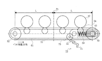
図3は比較対象としてのベルト駆動装置の構成を示す側面図、図4は比較対象としてのベルト駆動装置の動作を示す第1の図、図5は比較対象としてのベルト駆動装置の動作を示す第2の図、図6は比較対象としてのベルト駆動装置の動作を示す第3の図である。 3 is a side view showing the configuration of a belt drive device as a comparison target, FIG. 4 is a first diagram showing the operation of the belt drive device as a comparison target, and FIG. 5 shows the operation of the belt drive device as a comparison target. FIG. 2 and FIG. 6 are third diagrams showing the operation of the belt driving device as a comparison target.
図3に示されるように、転写部のベルト駆動装置は、ベルトフレーム161に回転可能に支持され、端部に歯車が固定係止された表面が高摩擦のドライブローラ152、両端部を軸受162に回転可能に支持されたアイドルローラ153等を有する。そして、前記軸受162は、ベルトフレーム161の図示されない穴に摺(しゅう)動可能に支持され、スプリング159によって付勢されて転写ベルト151を張架する。これにより、該転写ベルト151は矢印aに示される方向に走行する。なお、142はOPCドラムであり、154は転写ローラである。
As shown in FIG. 3, the belt driving device of the transfer unit is rotatably supported by a
そして、前記ベルトフレーム161には、ローラ軸変位部材としてのアーム163が回転軸163aに回転可能に支持され、アーム163の穴163bには軸受162が摺動可能に配設され、アイドルローラ153を回転可能に支持する。なお、該アイドルローラ153の一端部には、図4〜6に示されるように、同軸上に回転可能に、かつ、軸方向に移動可能なプーリ165が配設されている。
In the
また、前記アーム163とプーリ165との間には、ドライブローラ152の回転軸O1に対して傾斜した回転軸164aを有するローラ軸変位部材としてのローラ傾動レバー164が配設される。該ローラ傾動レバー164は、転写ベルト151の蛇行に応じてアイドルローラ153の軸を、図4〜6に示されるように傾動させる。
A
ここで、クリーニングブレード170はホルダ171とブレード172とを備える。そして、前記ホルダ171が軸受162の下方に延在するブレードブラケット174に係止され、クリーニングブレード170は、アイドルローラ153の傾動に応じ、同様に傾動する。
Here, the
しかし、アイドルローラ153の一端には、該アイドルローラ153の径より大きな径のフランジ部を持つプーリ165が配設されているので、クリーニングブレード170を前記プーリ165のフランジ部に跨(またが)るように設けることができない。そのため、図4に示されるように、転写ベルト151が最も右側に寄った場合には、該転写ベルト151の幅全体に亘ってクリーニングを行うことが可能であるが、図5及び6に示されるように、転写ベルト151が左側に寄った場合には、クリーニングを行うことができない領域、すなわち、クリーニング不可領域が発生してしまう。そして、該クリーニング不可領域が発生した状態で画像形成装置の運転を続けると、前記クリーニング不可領域にトナーなどの異物が堆積してしまい、ベルト駆動装置の周辺が汚染されたり、ドライブローラ152の表面に異物が付着して摩擦力が低下し、転写ベルト151を駆動することができなくなるなどの不具合が生じる。
However, since the
そこで、本実施の形態におけるベルト駆動装置では、クリーニング不可領域が発生しないようになっている。次に、本実施の形態におけるベルト駆動装置の構成を詳細に説明する。 Therefore, in the belt driving device according to the present embodiment, a non-cleanable area does not occur. Next, the configuration of the belt driving device in the present embodiment will be described in detail.
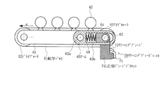
図1は本発明の第1の実施の形態におけるベルト駆動装置の構成を示す側面図、図7は本発明の第1の実施の形態におけるベルト駆動装置の動作を示す第1の図、図8は本発明の第1の実施の形態におけるベルト駆動装置の動作を示す第2の図、図9は本発明の第1の実施の形態におけるベルト駆動装置の動作を示す第3の図である。 FIG. 1 is a side view showing the configuration of the belt driving apparatus according to the first embodiment of the present invention. FIG. 7 is a first diagram showing the operation of the belt driving apparatus according to the first embodiment of the present invention. FIG. 9 is a second diagram showing the operation of the belt driving device according to the first embodiment of the present invention, and FIG. 9 is a third diagram showing the operation of the belt driving device according to the first embodiment of the present invention.
図1に示されるように、本実施の形態において、転写部50のベルト駆動装置は、ベルトフレーム61に回転可能に支持され、端部に図示されない歯車が固定係止された表面が高摩擦のドライブローラ52、両端部を軸受62に回転可能に支持されたアイドルローラ53等を有する。そして、前記軸受62は、ベルトフレーム61の穴に摺動可能に支持され、スプリング59によって付勢されて転写ベルト51を張架する。これにより、該転写ベルト51は矢印aに示される方向に走行する。なお、転写ベルト51は、ポリイミド、ウレタン等の弾性を有する樹脂から成り、遠心成形されるが、これはあくまでも一例であり、その他の材料が使用されることもある。
As shown in FIG. 1, in the present embodiment, the belt driving device of the
また、前記ベルトフレーム61には、ローラ軸変位部材としてのアーム63が回転軸63aに回転可能に支持され、アーム63の穴63bには軸受62が摺動可能に配設され、アイドルローラ53を回転可能に支持する。
The
そして、図7〜9に示されるように、アイドルローラ53の一端部の同軸上には、外周に転写ベルト51の端部に接するフランジ部が設けられ、その外側には外周に溝が形成されたプーリ65が回転可能に、かつ、軸方向に摺動可能に配設され、軸方向検知部材として機能する。また、前記プーリ65の溝に回転可能に係合するように左側ブレードブラケット74Lが取り付けられる。さらに、アイドルローラ53の他端には該アイドルローラ53の軸に回転可能に係合するように右側ブレードブラケット74Rが取り付けられる。なお、前記左側ブレードブラケット74L及び右側ブレードブラケット74Rを統合的に説明する場合には、ブレードブラケット74として説明する。
As shown in FIGS. 7 to 9, a flange portion that is in contact with the end portion of the
また、クリーニングブレードユニット70は、ホルダ71と、転写ベルト51に当接された弾性体から成るクリーニングブレード72とを備える。そして、前記ホルダ71の両端が左側ブレードブラケット74L及び右側ブレードブラケット74Rに各々係止されている。また、前記左側ブレードブラケット74L及び右側ブレードブラケット74Rは図示されない回動規制部材によって、回動しないように規制されている。そのため、ブレードブラケット74及びクリーニングブレードユニット70は、プーリ65に対して回転可能に取り付けられ、プーリ65と一体的にアイドルローラ53の軸方向に移動可能となっている。この場合、前記プーリ65、左側ブレードブラケット74L及び右側ブレードブラケット74Rは、クリーニングブレードユニット70をアイドルローラ53の軸方向へ移動させる移動機構として機能する。また、クリーニングブレードユニット70は、アイドルローラ53の傾動に応じ、同様に傾動する。なお、クリーニングブレードユニット70の幅は、転写ベルト51の幅と同じか、若干広くなっている。
The
そして、前記アーム63とプーリ65との間には、ドライブローラ52の回転軸O1に対して傾斜した回転軸64aを有するローラ軸変位部材としてのローラ傾動レバー64が配設される。
Between the arm 63 and the
次に、該ローラ傾動レバー64について説明する。
Next, the
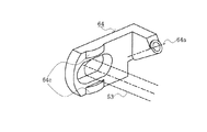
図10は本発明の第1の実施の形態におけるローラ傾動レバーの三面図、図11は本発明の第1の実施の形態におけるローラ傾動レバーを示す斜視図、図12は本発明の第1の実施の形態におけるローラ傾動レバーの動作を示す図である。なお、図10(a)はローラ傾動レバーの上面図、図10(b)はローラ傾動レバーの側面図、図10(c)はローラ傾動レバーの正面図である。 FIG. 10 is a three-sided view of the roller tilt lever in the first embodiment of the present invention, FIG. 11 is a perspective view showing the roller tilt lever in the first embodiment of the present invention, and FIG. 12 is the first view of the present invention. It is a figure which shows operation | movement of the roller tilting lever in embodiment. 10A is a top view of the roller tilt lever, FIG. 10B is a side view of the roller tilt lever, and FIG. 10C is a front view of the roller tilt lever.
図10及び11に示されるように、ローラ傾動レバー64はドライブローラ52の回転軸O1に対して角度θだけ傾斜した回転軸64aを有し、楕(だ)円孔(あな)部64bにはアイドルローラ53の軸が回転可能に、かつ、スライド可能に貫通され、プーリ65に接するように凸部64cが配設される。
As shown in FIGS. 10 and 11, the
前記ローラ傾動レバー64は傾斜した回転軸64aを有するので、回転した場合には、図10(b)に示されるような軌跡64dを描いて回転する。したがって、アイドルローラ53の軸端部が図1における下方向に傾斜した場合は、ローラ傾動レバー64も下方向で、かつ、アイドルローラ53に近付く方向に回転し、プーリ65を押し込むように動作する。また、同様にアイドルローラ53の軸端部が上方向に傾斜した場合は、ローラ傾動レバー64も上方向で、かつ、アイドルローラ53から離れる方向に回転する。そして、ローラ傾動レバー64が回転軸64aを中心にして回転する際に、前記ローラ傾動レバー64の姿勢は、図12に示されるように、連続的に変化するようになっている。
Since the
なお、本実施の形態においては、転写ベルト51の清掃手段がクリーニングブレードユニット70である例について説明したが、ファーブラシローラを用いて転写ベルト51上のトナーや異物を掻き落とす清掃手段、回転可能なクリーニングローラを転写ベルト51に当接させて、転写ベルト51上のトナーや異物を前記クリーニングローラに一旦(たん)付着させ、該クリーニングローラにクリーニングブレードを当接させて清掃する清掃手段、これらの清掃手段を適宜組み合わせた清掃手段を用いて、前記転写ベルト51上のトナーや異物を除去することもできる。
In this embodiment, an example in which the cleaning unit of the
次に、前記構成のベルト駆動装置の動作について説明する。 Next, the operation of the belt driving apparatus having the above configuration will be described.
まず、図7に示されるように、転写ベルト51が右側に寄っている場合、プーリ65は転写ベルト51の側面に接するように右側に位置している。それに従って、ローラ傾動レバー64は、アイドルローラ53の自重によって下方向に移動するとともに回転軸64aを中心に回転し、アイドルローラ53側に付勢される。そのため、該アイドルローラ53は図7に示されるように傾動する。このとき、クリーニングブレードユニット70は、ブレードブラケット74を介してプーリ65とともに、すなわち、転写ベルト51とともに右側に移動する。
First, as shown in FIG. 7, when the
そして、ドライブローラ52が回転して転写ベルト51が走行を始めると、矢印Cに示される方向に転写ベルト51が蛇行する。そして、プーリ65は、転写ベルト51に押され、矢印Cに示される方向にクリーニングブレードユニット70とともに移動する。
When the
前記ローラ傾動レバー64は、凸部64cによってプーリ65と接触しているので、該プーリ65に押されて傾斜した回転軸64aを中心に回転し、図8に示されるような位置になる。
Since the
この場合も、クリーニングブレードユニット70は転写ベルト51とともに移動する。図8に示されるような状態においては、アイドルローラ53の回転軸O2とドライブローラ52の回転軸O1とがほぼ平行になるので、転写ベルト51の蛇行は減少してこの位置で収まる。そのため、転写ベルト51は安定して走行することになる。
Also in this case, the
また、転写ベルト51が左側に寄っている場合、プーリ65も左側に位置し、これに伴ってローラ傾動レバー64は左側に付勢されるので、回転軸64aを中心として回転し、図9に示されるように、アイドルローラ53が傾動する。
When the
そして、該アイドルローラ53が傾動した場合は、走行することによって転写ベルト51が矢印Bに示される方向に蛇行するので、プーリ65は同様に矢印Bに示される方向に移動する。ローラ傾動レバー64は、アイドルローラ53の自重によって凸部64cがプーリ65に接するように下方向に、かつ、アイドルローラ53側に回転し、図8に示されるような状態で転写ベルト51は安定して走行する。この場合も、同様に、クリーニングブレードユニット70は転写ベルト51とともに移動する。
When the
本実施の形態においては、クリーニングブレードユニット70が転写ベルト51の軸方向検知部材としてのプーリ65と一体で移動するため、従来、転写ベルト51の蛇行によって発生していたクリーニング不可領域の発生はなくなる。
In the present embodiment, since the
このように、本実施の形態においては、クリーニングブレードユニット70が転写ベルト51の軸方向検知部材としてのプーリ65とともに移動するので、転写ベルト51が蛇行した際にクリーニングブレードユニット70の位置と転写ベルト51の位置とがずれることがない。そのため、クリーニングブレードユニット70が転写ベルト51に当接しないために発生するクリーニング不可領域の発生を防止することができる。これにより、クリーニング不可領域にトナーなどの異物が堆積してしまい、ベルト駆動装置の周辺が汚染されたり、転写ベルト51を駆動するドライブローラ52の表面に異物が付着して摩擦力が低下し、転写ベルト51を駆動することができなくなるなどの問題を解決することができる。
As described above, in the present embodiment, the
次に、本発明の第2の実施の形態について説明する。なお、第1の実施の形態と同じ構成を有するものについては、同じ符号を付与することによって、その説明を省略する。また、前記第1の実施の形態と同じ動作及び効果についても、その説明を省略する。 Next, a second embodiment of the present invention will be described. In addition, about what has the same structure as 1st Embodiment, the description is abbreviate | omitted by providing the same code | symbol. The description of the same operations and effects as those of the first embodiment is also omitted.
図13は本発明の第2の実施の形態におけるベルト駆動装置の構成を示す図である。 FIG. 13 is a diagram showing the configuration of the belt driving device according to the second embodiment of the present invention.
本実施の形態においては、前記第1の実施の形態における左側ブレードブラケット74L及び右側ブレードブラケット74Rが省略されている。そして、本実施の形態における転写部50のベルト駆動装置は、図13に示されるように、ベルトフレーム61には回転可能に取り付けられた付勢部材としてのサポートローラ75を有する。なお、クリーニングブレードユニット70は、図示されないフレーム部材に取り付けられ、前記サポートローラ75に対向した位置で転写ベルト51に当接するように配設される。
In the present embodiment, the
ここで、ドライブローラ52とアイドルローラ53との略中間点をP1とすると、前記サポートローラ75及びクリーニングブレート70は、P1よりもアイドルローラ53寄りであって、アイドルローラ53の上流側に位置する。そして、前記サポートローラ75は、ドライブローラ52とアイドルローラ53とが平行に位置した状態で張架された転写ベルト51の内面に接するように配設される。
Here, assuming that a substantially intermediate point between the
また、クリーニングブレードユニット70の幅は、転写ベルト51の幅に該転写ベルト51の蛇行幅を加えた値と同じか、又は、該値より大きくなっている。これにより、クリーニングブレードユニット70は、前記転写ベルト51の蛇行範囲を含む幅全体に亘り清掃可能となっている。
The width of the
次に、本実施の形態におけるベルト駆動装置の動作について説明する。 Next, the operation of the belt driving device in the present embodiment will be described.
図14は本発明の第2の実施の形態におけるベルト駆動装置の動作を示す第1の図、図15は本発明の第2の実施の形態におけるベルト駆動装置の動作を示す第2の図、図16は本発明の第2の実施の形態におけるベルト駆動装置の動作を示す第3の図、図17は図15と比較する本発明の第1の実施の形態におけるベルト駆動装置の動作を示す図、図18は図16と比較する本発明の第1の実施の形態におけるベルト駆動装置の動作を示す図である。 FIG. 14 is a first diagram illustrating the operation of the belt driving device according to the second embodiment of the present invention. FIG. 15 is a second diagram illustrating the operation of the belt driving device according to the second embodiment of the present invention. FIG. 16 is a third diagram illustrating the operation of the belt driving device according to the second embodiment of the present invention, and FIG. 17 illustrates the operation of the belt driving device according to the first embodiment of the present invention compared with FIG. 18 and 18 are diagrams showing the operation of the belt driving apparatus according to the first embodiment of the present invention compared with FIG.
なお、転写ベルト51が蛇行した場合に、アイドルローラ53が傾動することによって、転写ベルト51の蛇行を打ち消す動作については、前記第1の実施の形態と同様であるので、説明を省略する。
Since the operation of canceling the meandering of the
ここでは、サポートローラ75及びクリーニングブレードユニット70をベルトフレーム61の中間点P1よりアイドルローラ53寄りに配設したことによる動作について説明する。
Here, the operation of the
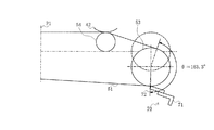
まず、ドライブローラ52とアイドルローラ53とが平行状態にある場合は、図14に示されるように、転写ベルト51は、アイドルローラ53の外周における中心角180.0度の範囲に亘って巻き付けられる。
First, when the
次に、アイドルローラ53が下方向に変位した場合、図15に示されるように、下側、すなわち、アイドルローラ53の上流側の転写ベルト51は、サポートローラ75及びクリーニングブレードユニット70によって、下向きに屈曲される。そして、アイドルローラ53の外周において転写ベルト51が巻き付けられる範囲の中心角は172.0度となる。
Next, when the
これに対し、前記第1の実施の形態におけるベルト駆動装置では、図17に示されるように、アイドルローラ53が下方向に変位した場合、アイドルローラ53の上流側の転写ベルト51は屈曲しない。そのため、アイドルローラ53の外周において転写ベルト51が巻き付けられる範囲の中心角は163.3度となる。
On the other hand, in the belt driving device according to the first embodiment, as shown in FIG. 17, when the
また、アイドルローラ53が上方向に変位した場合、図16に示されるように、アイドルローラ53の上流側の転写ベルト51は、サポートローラ75及びクリーニングブレードユニット70によって、上向きに屈曲される。そして、アイドルローラ53の外周において転写ベルト51が巻き付けられる範囲の中心角は188.9度となる。
When the
これに対し、前記第1の実施の形態におけるベルト駆動装置では、図18に示されるように、アイドルローラ53が上方向に変位した場合、アイドルローラ53の上流側の転写ベルト51は屈曲しない。そのため、アイドルローラ53の外周において転写ベルト51が巻き付けられる範囲の中心角は199.4度となる。
On the other hand, in the belt driving device according to the first embodiment, as shown in FIG. 18, when the
このことから、本実施の形態においては、アイドルローラ53が上下方向に変位した際に、アイドルローラ53の外周において転写ベルト51が巻き付けられる範囲の中心角、すなわち、転写ベルト51の巻き掛け角度の変動が、前記第1の実施の形態と比較して、小さいことが分かる。本実施の形態における転写ベルト51の巻き掛け角度の変動と、前記第1の実施の形態における転写ベルト51の巻き掛け角度の変動との比較をまとめると、次の(1)及び(2)に示されるようになる。
(1)アイドルローラ下方向変位
本実施の形態:(平行状態)180. 0度→(変位後)172. 0度(8. 0度変化)
第1の実施の形態:(平行状態)180. 0度→(変位後)163. 3度(16. 7度変化)
(2)アイドルローラ上方向変位
本実施の形態:(平行状態)180. 0度→(変位後)188. 9度(8. 9度変化)
第1の実施の形態:(平行状態)180. 0度→(変位後)199. 4度(19. 4度変化)
一般的に、複数のローラに張架されたベルトの蛇行は、該ベルトを張架する複数のローラとの平行度に起因し、巻き掛け角度の大きいロ−ラほど、ベルトの蛇行に与える影響が大きいことが分かっている。そのため、ローラを傾動させてベルトの蛇行を補正する場合、ローラへのベルトの巻き掛け角度が変動するということは、補正動作が不安定になるということであり、補正時間の延長や、補正精度の悪化などの問題を発生させる。
Therefore, in the present embodiment, when the
(1) Idle roller downward displacement This embodiment: (Parallel state) 180.0 degrees → (After displacement) 172.0 degrees (change of 8.0 degrees)
First embodiment: (Parallel state) 180.0 degrees → (after displacement) 163.3 degrees (16.7 degrees change)
(2) Idle roller upward displacement This embodiment: (Parallel state) 180.0 degrees → (After displacement) 188.9 degrees (8.9 degrees change)
First embodiment: (parallel state) 180.0 degrees → (after displacement) 199.4 degrees (19.4 degrees change)
In general, the meandering of a belt stretched around a plurality of rollers is caused by the parallelism with the plurality of rollers that stretch the belt, and a roller with a larger winding angle has an effect on the meandering of the belt. Is known to be large. Therefore, when correcting the meandering of the belt by tilting the roller, the fluctuation of the winding angle of the belt around the roller means that the correction operation becomes unstable, and the correction time is extended and the correction accuracy is increased. Causes problems such as deterioration.
なお、アイドルローラ53の他端、すなわち、ローラ傾動レバー64が配設されていない側では、アイドルローラ53は上下方向に変位しないので、アイドルローラ53の外周において転写ベルト51が巻き付けられる範囲の中心角は180.0度のまま変化しない。
Note that the
そのため、本実施の形態の形態においては、アイドルローラ53の幅全体に亘って巻き掛け角度の変動が少なくなり、アイドルローラ53を傾動させることで転写ベルト51の蛇行を低減して打ち消す動作が更に安定するとともに、転写ベルト51の幅全体に亘りクリーニングが可能となるものである。
For this reason, in the present embodiment, the fluctuation of the winding angle is reduced over the entire width of the
また、本実施の形態においては、ドライブローラ52とアイドルローラ53との2本のローラで転写ベルト51を張架した例について説明したが、3本以上のローラを使用する場合は、転写ベルト51の蛇行を補正するローラとその上流側に位置するローラとの間の略中間点より、蛇行を補正するローラ寄りの位置に、クリーニングブレードユニット70及びサポートローラ75を配設することによって、本実施の形態と同様の効果を得ることができる。
In this embodiment, the example in which the
このように、本実施の形態においては、クリーニングブレードユニット70と、該クリーニングブレードユニット70に対向する回転可能なサポートローラ75とが、転写ベルト51の蛇行を補正するローラとしてのアイドルローラ53と、その上流側に位置するローラとしてのドライブローラ52との間の略中間点P1より、アイドルローラ53寄りの位置に配設されている。そのため、転写ベルト51の幅全体に亘るクリーニングを可能にするばかりでなく、アイドルローラ53が変位した場合の転写ベルト51の巻き掛け角度の変動を最小限にとどめ、安定した転写ベルト51の蛇行補正動作を実現することができる。これにより、クリーニングブレードユニット70が転写ベルト51に当接しないために発生するクリーニング不可領域の発生を防止することができる。そして、クリーニング不可領域にトナーなどの異物が堆積してしまい、ベルト駆動装置の周辺が汚染されたり、転写ベルト51を駆動するドライブローラ52の表面に異物が付着して摩擦力が低下し、転写ベルト51を駆動することができなくなるなどの問題を解決することができる。さらに、転写ベルト51の蛇行補正時間の短縮及び補正の高精度化が可能となる。
Thus, in the present embodiment, the
次に、本発明の第3の実施の形態について説明する。なお、第1及び第2の実施の形態と同じ構成を有するものについては、同じ符号を付与することによって、その説明を省略する。また、前記第1及び第2の実施の形態と同じ動作及び同じ効果についても、その説明を省略する。 Next, a third embodiment of the present invention will be described. In addition, about the thing which has the same structure as 1st and 2nd embodiment, the description is abbreviate | omitted by providing the same code | symbol. Also, the description of the same operations and effects as those of the first and second embodiments is omitted.
図19は本発明の第3の実施の形態におけるベルト駆動装置の構成を示す図である。 FIG. 19 is a diagram showing the configuration of the belt driving device according to the third embodiment of the present invention.
本実施の形態においては、図19に示されるように、サポートローラ75及びクリーニングブレート70は、ドライブローラ52とアイドルローラ53との略中間点P1よりもドライブローラ52寄りに位置する。なお、その他の点の構成については、前記第2の実施の形態と同様であるので、説明を省略する。
In the present embodiment, as shown in FIG. 19, the
次に、本実施の形態におけるベルト駆動装置の動作について説明する。 Next, the operation of the belt driving device in the present embodiment will be described.
図20は本発明の第3の実施の形態におけるベルト駆動装置の動作を示す図、図21は図20と比較する本発明の第2の実施の形態におけるベルト駆動装置の動作を示す図である。 FIG. 20 is a diagram illustrating the operation of the belt driving device according to the third embodiment of the present invention, and FIG. 21 is a diagram illustrating the operation of the belt driving device according to the second embodiment of the present invention compared with FIG. .
本実施の形態においては、前述のように、サポートローラ75及びクリーニングブレート70は、略中間点P1よりもドライブローラ52寄りに位置するが、アイドルローラ53が変位した場合の転写ベルト51の巻き掛け角度の変動は、前記第2の実施の形態と同様に、前記第1の実施の形態と比較して小さくなっている。
In the present embodiment, as described above, the
ここで、図20に示されるように、アイドルローラ53が下方向に変位した場合、クリーニングブレードユニット70に接する箇所で転写ベルト51が屈曲し、該転写ベルト51の張力の合力がクリーニングブレードユニット70をサポートローラ75から離間させる方向、すなわち、クリーニングブレードユニット70と転写ベルト51との当接力が増加する方向に作用する。この場合、転写ベルト51の屈曲角度は5. 8度である。
Here, as shown in FIG. 20, when the
これに対し、前記第2の実施の形態におけるベルト駆動装置では、クリーニングブレードユニット70がアイドルローラ53により近い位置に配設されているので、図21に示されるように、アイドルローラ53が下方向に変位した場合、転写ベルト51の屈曲角度は、本実施の形態よりも大きく、11.6度となっている。そのため、転写ベルト51の張力の合力も、本実施の形態よりも大きくなっている。
On the other hand, in the belt driving device according to the second embodiment, the
本実施の形態における転写ベルト51の屈曲角度及び転写ベルト51の張力の合力と、前記第2の実施の形態における転写ベルト51の屈曲角度及び転写ベルト51の張力の合力との比較をまとめると、次の(3)及び(4)に示されるようになる。なお、ベルト張力は3〔kg〕であるとする。
(3)転写ベルト屈曲角度
本実施の形態:5. 8度
第2の実施の形態:11. 6度
(4)張力の合力
本実施の形態:0. 3〔kg〕
第2の実施の形態:0. 6〔kg〕
このことから、本実施の形態においては、転写ベルト51の屈曲角度及び転写ベルト51の張力の合力が、第2の実施の形態と比較して、50〔%〕程度に低減されていることが分かる。
The comparison between the bending angle of the
(3) Bending angle of transfer belt This embodiment: 5.8 degrees Second embodiment: 11.6 degrees (4) Combined tension This embodiment: 0.3 [kg]
Second embodiment: 0.6 [kg]
For this reason, in this embodiment, the resultant force of the bending angle of the
なお、アイドルローラ53の他端、すなわち、ローラ傾動レバー64が配設されていない側では、アイドルローラ53は上下方向に変位しないので、転写ベルト51の屈曲角度は0度となり、転写ベルト51の張力の合力は0〔kg〕となる。そのため、本実施の形態の形態においては、転写ベルト51の幅全体に亘ってクリーニングブレードユニット70と転写ベルト51との当接力の差が低減される。
Note that, at the other end of the
そして、クリーニングブレードユニット70と転写ベルト51との当接力は、クリーニング性能に大きな影響を与える。例えば、当接力が高いと、クリーニング能力は当然上がるが、転写ベルト51との摩擦力が増加するため、クリーニングブレードユニット70が転写ベルト51の回転方向下流側へ捲(めく)れてしまう問題が発生する。逆に、当接力が低いと、捲れる問題は発生しないが、クリーニング能力は低下し、転写ベルト51からトナーや異物を掻き落とすことができなくなってしまう。
The contact force between the
また、本実施の形態においては、ドライブローラ52とアイドルローラ53との2本のローラで転写ベルト51を張架した例について説明したが、3本以上のローラを使用する場合は、転写ベルト51の蛇行を補正するローラとその上流側に位置するローラとの間の略中間点より、上流側に位置するローラ寄りの位置に、クリーニングブレードユニット70及びサポートローラ75を配設することによって、本実施の形態と同様の効果を得ることができる。
In this embodiment, the example in which the
このように、本実施の形態においては、クリーニングブレードユニット70と、該クリーニングブレードユニット70に対向する回転可能なサポートローラ75とが、転写ベルト51の蛇行を補正するローラとしてのアイドルローラ53と、その上流側に位置するローラとしてのドライブローラ52との間の略中間点P1より、ドライブローラ52寄りの位置に配設されている。そのため、転写ベルト51の幅全体に亘るクリーニングを可能にするばかりでなく、アイドルローラ53が下方向に変位した場合のクリーニングブレードユニット70との当接箇所での転写ベルト51の屈曲角度を小さくすることができるので、転写ベルト51の張力によって発生するクリーニングブレードユニット70と転写ベルト51との当接力を低減し、安定したクリーニング性能を発揮させることができる。これにより、クリーニングブレードユニット70が転写ベルト51に当接しないために発生するクリーニング不可領域の発生を防止することができる。そして、該クリーニング不可領域にトナーなどの異物が堆積してしまい、ベルト駆動装置の周辺が汚染されたり、転写ベルト51を駆動するドライブローラ52の表面に異物が付着して摩擦力が低下し、転写ベルト51を駆動することができなくなるなどの問題を解決することができる。さらに、クリーニングブレードユニット70と転写ベルト51との当接力が増加することによって発生するクリーニングブレードユニット70の捲れや、クリーニング性能の低下のような問題をも解決することができる。
Thus, in the present embodiment, the
本実施の形態の転写ベルト51は、用紙11を搬送し、この搬送される用紙11に画像が形成される例について説明したが、転写ベルト51に直接画像を形成し、その後に用紙11に画像を転写させる中間転写方式の電子写真プリンタの転写ベルトにも適用可能である。
The
また、本発明は前記実施の形態に限定されるものではなく、本発明の趣旨に基づいて種々変形させることが可能であり、それらを本発明の範囲から排除するものではない。 The present invention is not limited to the above-described embodiment, and various modifications can be made based on the spirit of the present invention, and they are not excluded from the scope of the present invention.
11 用紙
40 画像形成部
51、151 転写ベルト
52、152 ドライブローラ
53、153 アイドルローラ
63、163 アーム
64、164 ローラ傾動レバー
65 プーリ
70 クリーニングブレードユニット
72、170 クリーニングブレード
74L 左側ブレードブラケット
74R 右側ブレードブラケット
75 サポートローラ
11
Claims (10)
(b)該ローラに張架された回転可能な無端ベルトと、
(c)複数の前記ローラのうちのいずれか1つのローラに対向して配設された清掃部材と、
(d)前記1つのローラの少なくとも一方の端部に配設され、前記ローラの軸方向への前記無端ベルトの移動に応じて前記ローラの軸に変位を与えるローラ軸変位部材と、
(e)該ローラ軸変位部材と連動し、前記1つのローラの軸方向への前記無端ベルトの移動とともに前記清掃部材を前記ローラの軸方向へ移動させる移動機構とを有し、
(f)前記ローラ軸変位部材は、前記ローラの軸方向への前記無端ベルトの移動とともに前記ローラの軸方向に移動し、前記ローラの軸方向の移動に伴って前記ローラの軸方向とほぼ垂直な方向へ移動して前記ローラの軸に変位を与えることを特徴とするベルト駆動装置。 (A) a plurality of rollers;
(B) a rotatable endless belt stretched around the roller;
(C) a cleaning member disposed to face any one of the plurality of rollers;
(D) a roller shaft displacement member that is disposed at at least one end of the one roller and applies displacement to the roller shaft in accordance with the movement of the endless belt in the axial direction of the roller;
(E) in conjunction with the roller shaft displacing member, have a moving mechanism for moving the cleaning member with the movement of the endless belt in the axial direction of said one roller to the axial direction of the roller,
(F) The roller shaft displacement member moves in the axial direction of the roller along with the movement of the endless belt in the axial direction of the roller, and is substantially perpendicular to the axial direction of the roller as the roller moves in the axial direction. belt drive, characterized in isosamples moved to a direction given displacement the axis of the roller.
(b)該クリーニングローラに当接された弾性体から成るクリーニングブレードとを備える請求項1又は2に記載のベルト駆動装置。 (A) the cleaning member includes a cleaning roller composed of a roller member in contact with the endless belt;
(B) a belt driving device according to claim 1 or 2 and a cleaning blade made of abutted elastic member to the cleaning roller.
(b)該ローラに張架された回転可能な無端ベルトと、
(c)前記無端ベルトの表面に当接する清掃部材と、
(d)前記無端ベルトを挟んで前記清掃部材に対向する位置に配設される付勢部材と、
(e)複数の前記ローラのうちの少なくとも1つのローラの少なくとも一方の端部に配設され、前記ローラの軸方向への前記無端ベルトの移動に応じて前記ローラの軸に変位を与えるローラ軸変位部材とを有し、
(f)該ローラ軸変位部材は、前記ローラの軸方向への前記無端ベルトの移動とともに前記ローラの軸方向に移動し、前記ローラの軸方向の移動に伴って前記ローラの軸方向とほぼ垂直な方向へ移動して前記ローラの軸に変位を与え、
(g)前記清掃部材及び付勢部材は、前記1つのローラに対して、前記無端ベルトの回転方向上流側に配設されることを特徴とするベルト駆動装置。 (A) a plurality of rollers;
(B) a rotatable endless belt stretched around the roller;
(C) a cleaning member that contacts the surface of the endless belt;
(D) a biasing member disposed at a position facing the cleaning member across the endless belt ;
(E) A roller shaft that is disposed at at least one end of at least one of the plurality of rollers and that displaces the roller shaft in accordance with the movement of the endless belt in the axial direction of the roller. A displacement member ,
(F) The roller shaft displacement member moves in the axial direction of the roller along with the movement of the endless belt in the axial direction of the roller, and substantially perpendicular to the axial direction of the roller as the roller moves in the axial direction. Moving in a different direction to give displacement to the roller shaft,
(G) the cleaning member and the biasing member, wherein for one of the rollers, the endless belt belt drive, characterized in that disposed upstream in the rotational direction of the.
Priority Applications (2)
| Application Number | Priority Date | Filing Date | Title |
|---|---|---|---|
| JP2005330999A JP4794281B2 (en) | 2005-11-16 | 2005-11-16 | Belt drive device and image forming apparatus having the same |
| US11/600,077 US7480471B2 (en) | 2005-11-16 | 2006-11-16 | Belt drive device and image forming apparatus having the same |
Applications Claiming Priority (1)
| Application Number | Priority Date | Filing Date | Title |
|---|---|---|---|
| JP2005330999A JP4794281B2 (en) | 2005-11-16 | 2005-11-16 | Belt drive device and image forming apparatus having the same |
Publications (3)
| Publication Number | Publication Date |
|---|---|
| JP2007139921A JP2007139921A (en) | 2007-06-07 |
| JP2007139921A5 JP2007139921A5 (en) | 2008-04-10 |
| JP4794281B2 true JP4794281B2 (en) | 2011-10-19 |
Family
ID=38040948
Family Applications (1)
| Application Number | Title | Priority Date | Filing Date |
|---|---|---|---|
| JP2005330999A Active JP4794281B2 (en) | 2005-11-16 | 2005-11-16 | Belt drive device and image forming apparatus having the same |
Country Status (2)
| Country | Link |
|---|---|
| US (1) | US7480471B2 (en) |
| JP (1) | JP4794281B2 (en) |
Families Citing this family (22)
| Publication number | Priority date | Publication date | Assignee | Title |
|---|---|---|---|---|
| KR101090057B1 (en) * | 2007-02-20 | 2011-12-07 | 삼성전자주식회사 | Image forming apparatus and belt cleaning unit thereof |
| JP5080832B2 (en) * | 2007-03-14 | 2012-11-21 | 京セラドキュメントソリューションズ株式会社 | Image forming apparatus |
| JP2009186902A (en) * | 2008-02-08 | 2009-08-20 | Seiko Epson Corp | Transfer device and image forming apparatus with the same |
| JP5151520B2 (en) * | 2008-02-08 | 2013-02-27 | コニカミノルタビジネステクノロジーズ株式会社 | Image forming apparatus |
| JP5282452B2 (en) * | 2008-06-12 | 2013-09-04 | 株式会社リコー | Image forming apparatus |
| JP5251309B2 (en) * | 2008-07-08 | 2013-07-31 | 株式会社リコー | Belt misalignment correction apparatus and image forming apparatus including the same |
| JP4766140B2 (en) | 2009-03-27 | 2011-09-07 | 富士ゼロックス株式会社 | Deviation correction apparatus, intermediate transfer apparatus, transfer apparatus, and image forming apparatus |
| US8351831B2 (en) | 2009-03-27 | 2013-01-08 | Fuji Xerox Co., Ltd. | Displacement correcting device, intermediate transfer device, transfer device, and image forming apparatus |
| JP2011107340A (en) * | 2009-11-16 | 2011-06-02 | Oki Data Corp | Belt driving device and image forming device |
| JP5409518B2 (en) * | 2010-05-31 | 2014-02-05 | 京セラドキュメントソリューションズ株式会社 | Belt conveying apparatus and image forming apparatus having the same |
| JP5312417B2 (en) * | 2010-09-17 | 2013-10-09 | 株式会社沖データ | Belt drive device and image forming apparatus having the same |
| NL2005940C2 (en) * | 2010-12-30 | 2012-07-03 | Marel Townsend Further Proc Bv | TRANSPORT DEVICE EQUIPPED WITH TORTABLE TRANSPORT TAPE AND METHOD FOR CONNECTING A TRANSPORT TAPE TO THE ENVIRONMENT. |
| JP5613612B2 (en) * | 2011-04-06 | 2014-10-29 | 京セラドキュメントソリューションズ株式会社 | Image forming apparatus |
| JP5727950B2 (en) * | 2012-01-30 | 2015-06-03 | 株式会社沖データ | Belt drive device and image forming apparatus |
| JP5968016B2 (en) * | 2012-04-06 | 2016-08-10 | キヤノン株式会社 | Fixing device |
| JP5891994B2 (en) * | 2012-08-06 | 2016-03-23 | ブラザー工業株式会社 | Image forming apparatus |
| JP6238537B2 (en) * | 2013-03-15 | 2017-11-29 | キヤノン株式会社 | Image forming apparatus |
| JP6260856B2 (en) * | 2013-11-07 | 2018-01-17 | 株式会社リコー | Belt device and image forming apparatus having the same |
| JP6292474B2 (en) * | 2014-03-17 | 2018-03-14 | 株式会社リコー | Belt device and image forming apparatus having the same |
| JP6963724B2 (en) * | 2017-10-06 | 2021-11-10 | 株式会社リコー | Belt device and image forming device |
| JP7124574B2 (en) * | 2018-03-30 | 2022-08-24 | 株式会社リコー | BELT DEVICE AND IMAGE FORMING APPARATUS |
| JP7288600B2 (en) * | 2019-05-20 | 2023-06-08 | 株式会社リコー | BELT DEVICE AND IMAGE FORMING APPARATUS |
Family Cites Families (10)
| Publication number | Priority date | Publication date | Assignee | Title |
|---|---|---|---|---|
| JP2868878B2 (en) * | 1990-09-26 | 1999-03-10 | バンドー化学株式会社 | Belt drive |
| JPH04247485A (en) * | 1991-02-01 | 1992-09-03 | Ricoh Co Ltd | Cleaning device |
| US6141525A (en) * | 1995-04-28 | 2000-10-31 | Canon Kabushiki Kaisha | Image forming apparatus having correction device for lateral misalignment |
| JP3262479B2 (en) * | 1995-07-10 | 2002-03-04 | キヤノン株式会社 | Image forming device |
| JP2000075680A (en) * | 1998-08-28 | 2000-03-14 | Fuji Xerox Co Ltd | Image forming device |
| JP2000284638A (en) * | 1999-03-29 | 2000-10-13 | Seiko Epson Corp | Image forming device |
| JP2000330394A (en) * | 1999-05-18 | 2000-11-30 | Canon Inc | Color image forming device |
| JP2002351228A (en) * | 2001-05-28 | 2002-12-06 | Canon Inc | Image forming apparatus |
| JP2005162466A (en) * | 2003-12-05 | 2005-06-23 | Samsung Electronics Co Ltd | Belt driving device |
| JP4413759B2 (en) | 2004-12-02 | 2010-02-10 | 株式会社沖データ | Belt drive device and image forming apparatus having the same |
-
2005
- 2005-11-16 JP JP2005330999A patent/JP4794281B2/en active Active
-
2006
- 2006-11-16 US US11/600,077 patent/US7480471B2/en active Active
Also Published As
| Publication number | Publication date |
|---|---|
| US20070110471A1 (en) | 2007-05-17 |
| JP2007139921A (en) | 2007-06-07 |
| US7480471B2 (en) | 2009-01-20 |
Similar Documents
| Publication | Publication Date | Title |
|---|---|---|
| JP4794281B2 (en) | Belt drive device and image forming apparatus having the same | |
| JP4413759B2 (en) | Belt drive device and image forming apparatus having the same | |
| US8478183B2 (en) | Image forming apparatus | |
| US9499363B2 (en) | Sheet thickness detector and image forming apparatus including same | |
| JP5251309B2 (en) | Belt misalignment correction apparatus and image forming apparatus including the same | |
| JP2009186910A (en) | Device for preventing belt skew and image forming apparatus provided with the same | |
| US20120034005A1 (en) | Sheet conveying apparatus | |
| JP2015013719A (en) | Sheet material thickness detection device and image forming apparatus using same | |
| JP4816677B2 (en) | Belt unit and image forming apparatus | |
| US7556260B2 (en) | Image forming apparatus | |
| JP4808115B2 (en) | Belt device and image forming apparatus | |
| JP2009237472A (en) | Image forming apparatus | |
| JP5063273B2 (en) | Belt conveying apparatus and image forming apparatus | |
| JP2011248056A (en) | Image forming apparatus | |
| JP2008129494A (en) | Belt conveyance device and image forming apparatus | |
| US20110241277A1 (en) | Medium feeding device and image forming apparatus | |
| JP2005326759A (en) | Intermediate transfer device and image forming apparatus | |
| JP5591572B2 (en) | Medium conveying apparatus and image forming apparatus | |
| JP5409040B2 (en) | Fixing apparatus and image forming apparatus having the same | |
| JP4303268B2 (en) | Conveying roller and image forming apparatus | |
| JP2007298811A (en) | Image forming apparatus | |
| JP2007223783A (en) | Belt conveyance device and image forming device | |
| US20230058521A1 (en) | Sheet conveyance apparatus and image forming apparatus | |
| JP4569907B2 (en) | Medium conveying apparatus and image forming apparatus | |
| JP2023113212A (en) | Fixing device and image forming apparatus |
Legal Events
| Date | Code | Title | Description |
|---|---|---|---|
| A621 | Written request for application examination |
Free format text: JAPANESE INTERMEDIATE CODE: A621 Effective date: 20080218 |
|
| A521 | Request for written amendment filed |
Free format text: JAPANESE INTERMEDIATE CODE: A523 Effective date: 20080221 |
|
| A977 | Report on retrieval |
Free format text: JAPANESE INTERMEDIATE CODE: A971007 Effective date: 20101116 |
|
| A131 | Notification of reasons for refusal |
Free format text: JAPANESE INTERMEDIATE CODE: A131 Effective date: 20101130 |
|
| A521 | Request for written amendment filed |
Free format text: JAPANESE INTERMEDIATE CODE: A523 Effective date: 20110125 |
|
| TRDD | Decision of grant or rejection written | ||
| A01 | Written decision to grant a patent or to grant a registration (utility model) |
Free format text: JAPANESE INTERMEDIATE CODE: A01 Effective date: 20110726 |
|
| A01 | Written decision to grant a patent or to grant a registration (utility model) |
Free format text: JAPANESE INTERMEDIATE CODE: A01 |
|
| A61 | First payment of annual fees (during grant procedure) |
Free format text: JAPANESE INTERMEDIATE CODE: A61 Effective date: 20110726 |
|
| R150 | Certificate of patent or registration of utility model |
Free format text: JAPANESE INTERMEDIATE CODE: R150 Ref document number: 4794281 Country of ref document: JP Free format text: JAPANESE INTERMEDIATE CODE: R150 |
|
| FPAY | Renewal fee payment (event date is renewal date of database) |
Free format text: PAYMENT UNTIL: 20140805 Year of fee payment: 3 |
|
| S111 | Request for change of ownership or part of ownership |
Free format text: JAPANESE INTERMEDIATE CODE: R313111 |
|
| R350 | Written notification of registration of transfer |
Free format text: JAPANESE INTERMEDIATE CODE: R350 |