JP6264128B2 - Combined cycle plant, control method thereof, and control device thereof - Google Patents
Combined cycle plant, control method thereof, and control device thereof Download PDFInfo
- Publication number
- JP6264128B2 JP6264128B2 JP2014058967A JP2014058967A JP6264128B2 JP 6264128 B2 JP6264128 B2 JP 6264128B2 JP 2014058967 A JP2014058967 A JP 2014058967A JP 2014058967 A JP2014058967 A JP 2014058967A JP 6264128 B2 JP6264128 B2 JP 6264128B2
- Authority
- JP
- Japan
- Prior art keywords
- steam
- turbine
- pressure
- steam turbine
- line
- Prior art date
- Legal status (The legal status is an assumption and is not a legal conclusion. Google has not performed a legal analysis and makes no representation as to the accuracy of the status listed.)
- Active
Links
Images


Classifications
-
- F—MECHANICAL ENGINEERING; LIGHTING; HEATING; WEAPONS; BLASTING
- F01—MACHINES OR ENGINES IN GENERAL; ENGINE PLANTS IN GENERAL; STEAM ENGINES
- F01K—STEAM ENGINE PLANTS; STEAM ACCUMULATORS; ENGINE PLANTS NOT OTHERWISE PROVIDED FOR; ENGINES USING SPECIAL WORKING FLUIDS OR CYCLES
- F01K23/00—Plants characterised by more than one engine delivering power external to the plant, the engines being driven by different fluids
- F01K23/02—Plants characterised by more than one engine delivering power external to the plant, the engines being driven by different fluids the engine cycles being thermally coupled
- F01K23/06—Plants characterised by more than one engine delivering power external to the plant, the engines being driven by different fluids the engine cycles being thermally coupled combustion heat from one cycle heating the fluid in another cycle
- F01K23/10—Plants characterised by more than one engine delivering power external to the plant, the engines being driven by different fluids the engine cycles being thermally coupled combustion heat from one cycle heating the fluid in another cycle with exhaust fluid of one cycle heating the fluid in another cycle
-
- F—MECHANICAL ENGINEERING; LIGHTING; HEATING; WEAPONS; BLASTING
- F01—MACHINES OR ENGINES IN GENERAL; ENGINE PLANTS IN GENERAL; STEAM ENGINES
- F01K—STEAM ENGINE PLANTS; STEAM ACCUMULATORS; ENGINE PLANTS NOT OTHERWISE PROVIDED FOR; ENGINES USING SPECIAL WORKING FLUIDS OR CYCLES
- F01K7/00—Steam engine plants characterised by the use of specific types of engine; Plants or engines characterised by their use of special steam systems, cycles or processes; Control means specially adapted for such systems, cycles or processes; Use of withdrawn or exhaust steam for feed-water heating
- F01K7/16—Steam engine plants characterised by the use of specific types of engine; Plants or engines characterised by their use of special steam systems, cycles or processes; Control means specially adapted for such systems, cycles or processes; Use of withdrawn or exhaust steam for feed-water heating the engines being only of turbine type
- F01K7/165—Controlling means specially adapted therefor
-
- F—MECHANICAL ENGINEERING; LIGHTING; HEATING; WEAPONS; BLASTING
- F01—MACHINES OR ENGINES IN GENERAL; ENGINE PLANTS IN GENERAL; STEAM ENGINES
- F01D—NON-POSITIVE DISPLACEMENT MACHINES OR ENGINES, e.g. STEAM TURBINES
- F01D19/00—Starting of machines or engines; Regulating, controlling, or safety means in connection therewith
-
- F—MECHANICAL ENGINEERING; LIGHTING; HEATING; WEAPONS; BLASTING
- F01—MACHINES OR ENGINES IN GENERAL; ENGINE PLANTS IN GENERAL; STEAM ENGINES
- F01K—STEAM ENGINE PLANTS; STEAM ACCUMULATORS; ENGINE PLANTS NOT OTHERWISE PROVIDED FOR; ENGINES USING SPECIAL WORKING FLUIDS OR CYCLES
- F01K11/00—Plants characterised by the engines being structurally combined with boilers or condensers
- F01K11/02—Plants characterised by the engines being structurally combined with boilers or condensers the engines being turbines
-
- F—MECHANICAL ENGINEERING; LIGHTING; HEATING; WEAPONS; BLASTING
- F01—MACHINES OR ENGINES IN GENERAL; ENGINE PLANTS IN GENERAL; STEAM ENGINES
- F01K—STEAM ENGINE PLANTS; STEAM ACCUMULATORS; ENGINE PLANTS NOT OTHERWISE PROVIDED FOR; ENGINES USING SPECIAL WORKING FLUIDS OR CYCLES
- F01K13/00—General layout or general methods of operation of complete plants
- F01K13/003—Arrangements for measuring or testing
-
- F—MECHANICAL ENGINEERING; LIGHTING; HEATING; WEAPONS; BLASTING
- F01—MACHINES OR ENGINES IN GENERAL; ENGINE PLANTS IN GENERAL; STEAM ENGINES
- F01K—STEAM ENGINE PLANTS; STEAM ACCUMULATORS; ENGINE PLANTS NOT OTHERWISE PROVIDED FOR; ENGINES USING SPECIAL WORKING FLUIDS OR CYCLES
- F01K13/00—General layout or general methods of operation of complete plants
- F01K13/02—Controlling, e.g. stopping or starting
-
- F—MECHANICAL ENGINEERING; LIGHTING; HEATING; WEAPONS; BLASTING
- F01—MACHINES OR ENGINES IN GENERAL; ENGINE PLANTS IN GENERAL; STEAM ENGINES
- F01K—STEAM ENGINE PLANTS; STEAM ACCUMULATORS; ENGINE PLANTS NOT OTHERWISE PROVIDED FOR; ENGINES USING SPECIAL WORKING FLUIDS OR CYCLES
- F01K7/00—Steam engine plants characterised by the use of specific types of engine; Plants or engines characterised by their use of special steam systems, cycles or processes; Control means specially adapted for such systems, cycles or processes; Use of withdrawn or exhaust steam for feed-water heating
- F01K7/16—Steam engine plants characterised by the use of specific types of engine; Plants or engines characterised by their use of special steam systems, cycles or processes; Control means specially adapted for such systems, cycles or processes; Use of withdrawn or exhaust steam for feed-water heating the engines being only of turbine type
- F01K7/22—Steam engine plants characterised by the use of specific types of engine; Plants or engines characterised by their use of special steam systems, cycles or processes; Control means specially adapted for such systems, cycles or processes; Use of withdrawn or exhaust steam for feed-water heating the engines being only of turbine type the turbines having inter-stage steam heating
- F01K7/24—Control or safety means specially adapted therefor
-
- F—MECHANICAL ENGINEERING; LIGHTING; HEATING; WEAPONS; BLASTING
- F02—COMBUSTION ENGINES; HOT-GAS OR COMBUSTION-PRODUCT ENGINE PLANTS
- F02C—GAS-TURBINE PLANTS; AIR INTAKES FOR JET-PROPULSION PLANTS; CONTROLLING FUEL SUPPLY IN AIR-BREATHING JET-PROPULSION PLANTS
- F02C3/00—Gas-turbine plants characterised by the use of combustion products as the working fluid
- F02C3/04—Gas-turbine plants characterised by the use of combustion products as the working fluid having a turbine driving a compressor
-
- F—MECHANICAL ENGINEERING; LIGHTING; HEATING; WEAPONS; BLASTING
- F02—COMBUSTION ENGINES; HOT-GAS OR COMBUSTION-PRODUCT ENGINE PLANTS
- F02C—GAS-TURBINE PLANTS; AIR INTAKES FOR JET-PROPULSION PLANTS; CONTROLLING FUEL SUPPLY IN AIR-BREATHING JET-PROPULSION PLANTS
- F02C6/00—Plural gas-turbine plants; Combinations of gas-turbine plants with other apparatus; Adaptations of gas- turbine plants for special use
- F02C6/18—Plural gas-turbine plants; Combinations of gas-turbine plants with other apparatus; Adaptations of gas- turbine plants for special use using the waste heat of gas-turbine plants outside the plants themselves, e.g. gas-turbine power heat plants
-
- F—MECHANICAL ENGINEERING; LIGHTING; HEATING; WEAPONS; BLASTING
- F05—INDEXING SCHEMES RELATING TO ENGINES OR PUMPS IN VARIOUS SUBCLASSES OF CLASSES F01-F04
- F05D—INDEXING SCHEME FOR ASPECTS RELATING TO NON-POSITIVE-DISPLACEMENT MACHINES OR ENGINES, GAS-TURBINES OR JET-PROPULSION PLANTS
- F05D2220/00—Application
- F05D2220/30—Application in turbines
- F05D2220/31—Application in turbines in steam turbines
-
- F—MECHANICAL ENGINEERING; LIGHTING; HEATING; WEAPONS; BLASTING
- F05—INDEXING SCHEMES RELATING TO ENGINES OR PUMPS IN VARIOUS SUBCLASSES OF CLASSES F01-F04
- F05D—INDEXING SCHEME FOR ASPECTS RELATING TO NON-POSITIVE-DISPLACEMENT MACHINES OR ENGINES, GAS-TURBINES OR JET-PROPULSION PLANTS
- F05D2220/00—Application
- F05D2220/30—Application in turbines
- F05D2220/32—Application in turbines in gas turbines
-
- F—MECHANICAL ENGINEERING; LIGHTING; HEATING; WEAPONS; BLASTING
- F05—INDEXING SCHEMES RELATING TO ENGINES OR PUMPS IN VARIOUS SUBCLASSES OF CLASSES F01-F04
- F05D—INDEXING SCHEME FOR ASPECTS RELATING TO NON-POSITIVE-DISPLACEMENT MACHINES OR ENGINES, GAS-TURBINES OR JET-PROPULSION PLANTS
- F05D2220/00—Application
- F05D2220/70—Application in combination with
- F05D2220/72—Application in combination with a steam turbine
-
- F—MECHANICAL ENGINEERING; LIGHTING; HEATING; WEAPONS; BLASTING
- F05—INDEXING SCHEMES RELATING TO ENGINES OR PUMPS IN VARIOUS SUBCLASSES OF CLASSES F01-F04
- F05D—INDEXING SCHEME FOR ASPECTS RELATING TO NON-POSITIVE-DISPLACEMENT MACHINES OR ENGINES, GAS-TURBINES OR JET-PROPULSION PLANTS
- F05D2260/00—Function
- F05D2260/60—Fluid transfer
- F05D2260/605—Venting into the ambient atmosphere or the like
-
- F—MECHANICAL ENGINEERING; LIGHTING; HEATING; WEAPONS; BLASTING
- F05—INDEXING SCHEMES RELATING TO ENGINES OR PUMPS IN VARIOUS SUBCLASSES OF CLASSES F01-F04
- F05D—INDEXING SCHEME FOR ASPECTS RELATING TO NON-POSITIVE-DISPLACEMENT MACHINES OR ENGINES, GAS-TURBINES OR JET-PROPULSION PLANTS
- F05D2260/00—Function
- F05D2260/85—Starting
-
- Y—GENERAL TAGGING OF NEW TECHNOLOGICAL DEVELOPMENTS; GENERAL TAGGING OF CROSS-SECTIONAL TECHNOLOGIES SPANNING OVER SEVERAL SECTIONS OF THE IPC; TECHNICAL SUBJECTS COVERED BY FORMER USPC CROSS-REFERENCE ART COLLECTIONS [XRACs] AND DIGESTS
- Y02—TECHNOLOGIES OR APPLICATIONS FOR MITIGATION OR ADAPTATION AGAINST CLIMATE CHANGE
- Y02E—REDUCTION OF GREENHOUSE GAS [GHG] EMISSIONS, RELATED TO ENERGY GENERATION, TRANSMISSION OR DISTRIBUTION
- Y02E20/00—Combustion technologies with mitigation potential
- Y02E20/16—Combined cycle power plant [CCPP], or combined cycle gas turbine [CCGT]
Description
本発明は、ガスタービンと複数の蒸気タービンとを備えているコンバインドサイクルプラント、その制御方法、及びその制御装置に関する。 The present invention relates to a combined cycle plant including a gas turbine and a plurality of steam turbines, a control method thereof, and a control device thereof.
複数の蒸気タービンを備えているプラントとしては、例えば、以下の特許文献1に記載されているものがある。このプラントは、蒸気を発生するボイラーと、ボイラーからの蒸気により駆動する複数の蒸気タービンと、蒸気タービンから排気された蒸気を水に戻す復水器と、を備えている。このプラントは、複数の蒸気タービンとして、高圧蒸気タービンと中圧蒸気タービンと低圧蒸気タービンとを備えている。また、ボイラーは、蒸気を発生する蒸気発生器と、この蒸気発生器で発生した蒸気を過熱する過熱器と、蒸気を再度加熱する再熱器とを備えている。
As a plant provided with a plurality of steam turbines, for example, there is one described in
ボイラーの過熱器と高圧蒸気タービンの蒸気入口とは、主蒸気ラインで接続されている。この主蒸気ラインには、主蒸気止め弁及び主蒸気加減弁が設けられている。高圧蒸気タービンの蒸気出口と中圧蒸気タービンの蒸気入口とは、高圧蒸気タービンから排気された蒸気をボイラーの再熱器を経て中圧蒸気タービンの蒸気入口に導く再熱蒸気ラインで接続されている。この再熱蒸気ラインで再熱器よりも下流側の部分には、再熱蒸気止め弁及びインターセプト弁が設けられている。中圧蒸気タービンの蒸気出口と低圧蒸気タービンの蒸気入口とは、低圧蒸気ラインで接続されている。低圧蒸気タービンには、この低圧蒸気タービンから排気された蒸気を復水に戻す復水器が設けられている。復水器とボイラーとは、給水ラインで接続されている。 The boiler superheater and the steam inlet of the high-pressure steam turbine are connected by a main steam line. The main steam line is provided with a main steam stop valve and a main steam control valve. The steam outlet of the high pressure steam turbine and the steam inlet of the intermediate pressure steam turbine are connected by a reheat steam line that guides the steam exhausted from the high pressure steam turbine to the steam inlet of the intermediate pressure steam turbine through the boiler reheater. Yes. In the reheat steam line, a reheat steam stop valve and an intercept valve are provided at a portion downstream of the reheater. The steam outlet of the intermediate pressure steam turbine and the steam inlet of the low pressure steam turbine are connected by a low pressure steam line. The low pressure steam turbine is provided with a condenser for returning the steam exhausted from the low pressure steam turbine to the condensate. The condenser and the boiler are connected by a water supply line.
主蒸気ラインと再熱蒸気ラインの再熱器より上流側の部分とは、高圧タービンバイパスラインで接続されている。この高圧タービンバイパスラインには、高圧バイパス弁が設けられている。再熱蒸気ラインの再熱器より上流側の部分と復水器とは、ベンチレータラインで接続されている。このベンチレータラインには、ベンチレータ弁が設けられている。 The main steam line and a portion upstream of the reheater of the reheat steam line are connected by a high-pressure turbine bypass line. This high pressure turbine bypass line is provided with a high pressure bypass valve. A portion upstream of the reheater in the reheat steam line and the condenser are connected by a ventilator line. The ventilator line is provided with a ventilator valve.
このプラントでは、起動時、高圧タービンバイパス弁及びベンチレータ弁が開状態で、高圧主蒸気止め弁が開けられと共に、高圧蒸気加減弁が徐々に開けられる。高圧蒸気タービンの通気開始過程では、高圧蒸気タービンの風損による排気蒸気の温度が上昇する。このため、ベンチレータ弁を開けて、高圧蒸気タービンの蒸気出口を復水器に接続して、高圧蒸気タービンの入口側と出口側との圧力差を大きくして、排気蒸気の温度上昇を抑制している。このベンチレータ弁は、高圧蒸気タービンに流入する高圧蒸気の流量、つまり高圧蒸気タービンの負荷が予め定められた負荷になると、閉じられる。 In this plant, at the time of start-up, the high-pressure turbine bypass valve and the ventilator valve are opened, the high-pressure main steam stop valve is opened, and the high-pressure steam control valve is gradually opened. In the ventilation start process of the high pressure steam turbine, the temperature of the exhaust steam rises due to the windage loss of the high pressure steam turbine. For this reason, the ventilator valve is opened, the steam outlet of the high-pressure steam turbine is connected to the condenser, the pressure difference between the inlet side and the outlet side of the high-pressure steam turbine is increased, and the temperature rise of the exhaust steam is suppressed. ing. The ventilator valve is closed when the flow rate of the high-pressure steam flowing into the high-pressure steam turbine, that is, the load of the high-pressure steam turbine becomes a predetermined load.
上記特許文献1に記載の技術では、起動過程で、開状態のベンチレータ弁が閉じられると、再熱蒸気ラインに流れる蒸気の流量が急激に増えることになる。このため、再熱蒸気ラインに関する制御系が一時的に不安定になるおそれがある。
In the technique described in
そこで、本発明は、起動過程で制御系が不安定になることを抑えることができる技術を提供することを目的とする。 Therefore, an object of the present invention is to provide a technique capable of suppressing the instability of the control system during the startup process.
上記目的を達成するための発明に係る一態様としての制御装置は、
燃焼ガスにより駆動するガスタービンと、前記ガスタービンから排気された燃焼ガスの熱により蒸気を発生する排熱回収ボイラーと、前記蒸気で駆動する第一及び第二蒸気タービンと、前記第二蒸気タービンから排気された蒸気を水に戻す復水器と、を備え、前記排熱回収ボイラーは、前記燃焼ガスの熱により前記第一蒸気タービンに供給する第一蒸気を発生する第一蒸気発生部と、前記第一蒸気タービンから排気された蒸気を加熱する再熱部と、を有し、前記排熱回収ボイラーの前記第一蒸気発生部と前記第一蒸気タービンとは、前記第一蒸気を前記第一蒸気タービンに導く第一蒸気ラインで接続され、前記第一蒸気タービンと前記第二蒸気タービンとは、前記第一蒸気タービンから排気された蒸気を前記排熱回収ボイラーの前記再熱部を経て前記第二蒸気タービンに導く再熱蒸気ラインで接続され、前記再熱蒸気ライン中で前記第一蒸気タービンから前記再熱部までの再熱前蒸気ラインと前記第一蒸気ラインとは、第一バイパスラインで接続され、前記再熱前蒸気ラインと前記復水器とは、第二バイパスラインで接続され、前記第二バイパスラインには、前記第二バイパスラインを通る蒸気の流量を調節するベンチレータ弁が設けられているコンバインドサイクルプラントの制御装置において、
前記第一蒸気タービン及び前記第二蒸気タービンの起動過程で、前記第一蒸気タービンに流入する前記第一蒸気の流量が規定流量になったか否かを設定されたしきい値から判断する判断部と、前記判断部により、前記第一蒸気タービンに流入する前記第一蒸気の流量が規定流量になったと判断されると、開状態の前記ベンチレータ弁に対して閉状態への移行を示す閉指令を出力する指令出力部と、前記排熱回収ボイラーの起動モードにおけるモードの種類に応じて前記しきい値を変更するしきい値変更部と、を有する。
A control device as one aspect according to the invention for achieving the above object is as follows:
A gas turbine driven by combustion gas, an exhaust heat recovery boiler that generates steam by heat of the combustion gas exhausted from the gas turbine, first and second steam turbines driven by the steam, and the second steam turbine A condenser that returns the steam exhausted from the water to the water, and the exhaust heat recovery boiler includes a first steam generating unit that generates the first steam to be supplied to the first steam turbine by the heat of the combustion gas; A reheat section for heating the steam exhausted from the first steam turbine, and the first steam generation section and the first steam turbine of the exhaust heat recovery boiler are configured to convert the first steam into the first steam turbine. The first steam turbine and the second steam turbine are connected by a first steam line that leads to the first steam turbine, and the steam that is exhausted from the first steam turbine is connected to the reheat part of the exhaust heat recovery boiler. Are connected by a reheat steam line leading to the second steam turbine, and in the reheat steam line, the pre-reheat steam line from the first steam turbine to the reheat section and the first steam line are: Connected by one bypass line, the steam line before reheating and the condenser are connected by a second bypass line, and the second bypass line adjusts the flow rate of steam passing through the second bypass line. In a combined cycle plant control device provided with a ventilator valve,
A determination unit that determines whether or not the flow rate of the first steam flowing into the first steam turbine has reached a specified flow rate in the starting process of the first steam turbine and the second steam turbine from a set threshold value. When the determination unit determines that the flow rate of the first steam flowing into the first steam turbine has reached a specified flow rate, a close command indicating a transition to the closed state with respect to the ventilator valve in the open state And a threshold value changing unit that changes the threshold value according to the mode type in the startup mode of the exhaust heat recovery boiler.
制御装置において、第一蒸気の発生量が多い場合でも少ない場合でも、判断部が規定流量になったか否かを判断するしきい値を仮に同じであるとする。すなわち、制御装置は、第一蒸気の発生量が少ない場合でも、第一蒸気の発生量の多い場合と同じしきい値で、第一蒸気タービンに流入する第一蒸気の流量が規定流量になったと判断すると仮定する。この仮定のもとでは、第一蒸気の発生量が少ない場合でも、第一蒸気タービンに流入する第一蒸気の流量が第一蒸気の発生量が多い場合のときの規定流量になったときに、ベンチレータ弁が閉じることになる。このため、この仮定のもとでは、第一蒸気の発生量が少ない場合でも、ベンチレータ弁が閉じる直前で、ベンチレータ弁を介して復水器に流入する第一蒸気の流量が、第一蒸気の発生量が多い場合のときの規定流量と実質的に同じ流量になる。また、この仮定のもとでは、第一バイパスラインを介して再熱蒸気ラインに流入する第一蒸気の流量が、第一蒸気の発生量が多い場合のときに第一バイパスラインを介して再熱蒸気ラインに流入する第一蒸気の流量よりも少なくなる。よって、この仮定のもとでは、ベンチレータ弁が閉じる前後における再熱蒸気ラインを流れる蒸気の流量変化率が、第一蒸気の発生量が多い場合よりも第一蒸気の発生量が少ない場合に大きくなる。このため、第一蒸気の発生量が少ない場合、再熱蒸気ラインに関する制御系が不安定になる可能性が高くなる。 In the control device, it is assumed that the threshold value for determining whether or not the determination unit has reached the specified flow rate is the same regardless of whether the first steam generation amount is large or small. That is, even when the amount of generated first steam is small, the control device sets the flow rate of the first steam flowing into the first steam turbine to the specified flow rate with the same threshold as when the amount of generated first steam is large. Assume that Under this assumption, even when the generation amount of the first steam is small, the flow rate of the first steam flowing into the first steam turbine becomes the specified flow rate when the generation amount of the first steam is large. The ventilator valve will close. Therefore, under this assumption, even when the amount of first steam generated is small, the flow rate of the first steam flowing into the condenser via the ventilator valve immediately before the ventilator valve is closed is The flow rate is substantially the same as the specified flow rate when the generated amount is large. Also, under this assumption, the flow rate of the first steam flowing into the reheat steam line through the first bypass line is regenerated through the first bypass line when the amount of generated first steam is large. This is less than the flow rate of the first steam flowing into the thermal steam line. Therefore, under this assumption, the rate of change in the flow rate of the steam flowing through the reheat steam line before and after the ventilator valve is closed is larger when the amount of first steam is smaller than when the amount of first steam is large. Become. For this reason, when there is little generation amount of 1st steam, possibility that the control system regarding a reheat steam line will become unstable becomes high.
ところで、プラントの起動過程では、第一蒸気発生部からの第一蒸気の温度とこの第一蒸気の発生量とには、正の相関性がある。つまり、プラントの起動過程では、第一蒸気発生部の第一蒸気の温度が高くなると、この第一蒸気の発生量が多くなり、第一蒸気発生部の第一蒸気の温度が低くなると、この第一蒸気の発生量が少なくなる。これは、第一蒸気の温度を高くするために、第一蒸気発生部に高いエネルギーを有する排ガスを供給する必要があり、必然的に第一蒸気の発生量が多くなるからである。また、プラントの起動過程では、第一蒸気の温度が高くなると、第一蒸気タービンに供給する第一蒸気の流量が多くなる。このため、プラントの起動過程では、第一蒸気の温度と第一蒸気タービンへ供給する第一蒸気の流量とには、正の相関性がある。これは、第一蒸気の温度が高くなると、高圧蒸気タービン出口の排気温度上昇を抑制するための必要蒸気量が多くなるからである。 By the way, in the start-up process of the plant, there is a positive correlation between the temperature of the first steam from the first steam generator and the amount of the first steam generated. That is, in the start-up process of the plant, when the temperature of the first steam of the first steam generation unit increases, the amount of generation of this first steam increases, and when the temperature of the first steam of the first steam generation unit decreases, this The amount of first steam generated is reduced. This is because in order to raise the temperature of the first steam, it is necessary to supply exhaust gas having high energy to the first steam generation section, and the amount of the first steam generated is inevitably increased. Moreover, in the start-up process of the plant, when the temperature of the first steam increases, the flow rate of the first steam supplied to the first steam turbine increases. For this reason, in the start-up process of the plant, there is a positive correlation between the temperature of the first steam and the flow rate of the first steam supplied to the first steam turbine. This is because as the temperature of the first steam increases, the amount of steam necessary for suppressing the exhaust temperature rise at the outlet of the high-pressure steam turbine increases.
そこで、当該制御装置では、判断部が規定流量になったか否かを判断するしきい値を、起動モードにおけるモードの種類に応じて、変更している。このため、当該制御装置では、第一蒸気発生部からの第一蒸気の発生量が少ないときには規定流量が小さくなり、ベンチレータ弁の閉じる前後での再熱蒸気ラインに流れる蒸気の流量変化率を小さくすることができる。 Therefore, in the control device, the threshold value for determining whether or not the determination unit has reached the specified flow rate is changed according to the type of mode in the startup mode . For this reason, in the said control apparatus, when the generation amount of the 1st steam from a 1st steam generation part is small, a regulation flow rate becomes small, and the flow rate change rate of the steam which flows into the reheat steam line before and behind closing a ventilator valve is made small. can do.
ここで、前記一態様としての前記制御装置において、前記排熱回収ボイラーの前記起動モードが少なくともコールドモードであるかホットモードであるかを認識する起動モード認識部を有し、前記しきい値変更部は、前記起動モード認識部が認識したモードの種類に応じて、前記しきい値を変更してもよい。 Here, in the control device as the one embodiment, it has the said activation mode or recognizing start mode recognition unit is a hot mode or at least cold mode of the exhaust heat recovery boiler, the threshold value change The unit may change the threshold value according to a type of mode recognized by the activation mode recognition unit.
また、前記起動モード認識部を有する前記制御装置において、前記起動モード認識部は、温度計で検知された前記第一蒸気タービンにおける蒸気接触部の温度に応じて前記起動モードの種類を認識してもよい。 Further, in the control device having the activation mode recognition unit, the activation mode recognition unit recognizes the type of the activation mode according to the temperature of the steam contact portion in the first steam turbine detected by a thermometer. Also good.
また、前記一態様としての前記制御装置において、前記しきい値は、前記第一蒸気タービンに流入する前記第一蒸気の圧力に関する値であってもよい。 Moreover, the said control apparatus as said 1 aspect WHEREIN: The value regarding the pressure of said 1st steam which flows in into said 1st steam turbine may be sufficient as the said threshold value .
また、前記一態様としての前記制御装置において、前記しきい値は、前記第一蒸気タービンに流入する前記第一蒸気の規定流量に対応する前記第一蒸気の圧力であってもよい。 In the control device according to the aspect, the threshold value may be a pressure of the first steam corresponding to a specified flow rate of the first steam flowing into the first steam turbine .
上記目的を達成するための発明に係る一態様としてのコンバインドサイクルプラントは、
以上のいずれかの前記制御装置と、前記ガスタービンと、前記排熱回収ボイラーと、前記第一蒸気タービンと、前記第二蒸気タービンと、前記復水器と、を備えている。
The combined cycle plant as one aspect according to the invention for achieving the above object is as follows:
One of the above control devices, the gas turbine, the exhaust heat recovery boiler, the first steam turbine, the second steam turbine, and the condenser are provided.
上記目的を達成するための発明に係る一態様としての制御方法は、
燃焼ガスにより駆動するガスタービンと、前記ガスタービンから排気された燃焼ガスの熱により蒸気を発生する排熱回収ボイラーと、前記蒸気で駆動する第一及び第二蒸気タービンと、前記第二蒸気タービンから排気された蒸気を水に戻す復水器と、を備え、前記排熱回収ボイラーは、前記燃焼ガスの熱により前記第一蒸気タービンに供給する第一蒸気を発生する第一蒸気発生部と、前記第一蒸気タービンから排気された蒸気を加熱する再熱部と、を有し、前記排熱回収ボイラーの前記第一蒸気発生部と前記第一蒸気タービンとは、前記第一蒸気を前記第一蒸気タービンに導く第一蒸気ラインで接続され、前記第一蒸気タービンと前記第二蒸気タービンとは、前記第一蒸気タービンから排気された蒸気を前記排熱回収ボイラーの前記再熱部を経て前記第二蒸気タービンに導く再熱蒸気ラインで接続され、前記再熱蒸気ライン中で前記第一蒸気タービンから前記再熱部までの再熱前蒸気ラインと前記第一蒸気ラインとは、第一バイパスラインで接続され、前記再熱前蒸気ラインと前記復水器とは、第二バイパスラインで接続され、前記第二バイパスラインには、前記第二バイパスラインを通る蒸気の流量を調節するベンチレータ弁が設けられているコンバインドサイクルプラントの制御方法において、
前記第一蒸気タービン及び前記第二蒸気タービンの起動過程で、前記第一蒸気タービンに流入する前記第一蒸気の流量が規定流量になったか否かを設定されたしきい値から判断する判断工程と、前記判断工程で、前記第一蒸気タービンに流入する前記第一蒸気の流量が規定流量になったと判断されると、開状態の前記ベンチレータ弁に対して閉状態への移行を示す閉指令を出力する指令出力工程と、前記排熱回収ボイラーの起動モードにおけるモードの種類に応じて前記しきい値を変更するしきい値変更工程と、を実行する。
A control method as one aspect according to the invention for achieving the above object is as follows:
A gas turbine driven by combustion gas, an exhaust heat recovery boiler that generates steam by heat of the combustion gas exhausted from the gas turbine, first and second steam turbines driven by the steam, and the second steam turbine A condenser that returns the steam exhausted from the water to the water, and the exhaust heat recovery boiler includes a first steam generating unit that generates the first steam to be supplied to the first steam turbine by the heat of the combustion gas; A reheat section for heating the steam exhausted from the first steam turbine, and the first steam generation section and the first steam turbine of the exhaust heat recovery boiler are configured to convert the first steam into the first steam turbine. The first steam turbine and the second steam turbine are connected by a first steam line that leads to the first steam turbine, and the steam that is exhausted from the first steam turbine is connected to the reheat part of the exhaust heat recovery boiler. Are connected by a reheat steam line leading to the second steam turbine, and in the reheat steam line, the pre-reheat steam line from the first steam turbine to the reheat section and the first steam line are: Connected by one bypass line, the steam line before reheating and the condenser are connected by a second bypass line, and the second bypass line adjusts the flow rate of steam passing through the second bypass line. In a control method of a combined cycle plant provided with a ventilator valve,
Wherein a first steam turbine and start the process of the second steam turbine, step determines the flow rate of the first steam is determined from a set whether it is prescribed rate threshold that flows into the first steam turbine When the determination step determines that the flow rate of the first steam flowing into the first steam turbine has reached a specified flow rate, a close command indicating a transition to the closed state with respect to the ventilator valve in the open state And a threshold value changing step for changing the threshold value in accordance with the mode type in the startup mode of the exhaust heat recovery boiler.
当該制御方法でも、前述の制御装置と同様、ベンチレータ弁の閉じる前後での再熱蒸気ラインに流れる蒸気の流量変化率を小さくすることができる。 Even in this control method, the rate of change in the flow rate of the steam flowing in the reheat steam line before and after the ventilator valve is closed can be reduced as in the above-described control device.
ここで、前記一態様としての前記制御方法において、前記排熱回収ボイラーの前記起動モードが少なくともコールドモードであるかホットモードであるかを認識する起動モード認識工程を実行し、前記しきい値変更工程では、前記起動モード認識工程で認識されたモードの種類に応じて、前記しきい値を変更してもよい。 Here, in the control method as the one aspect, a start mode recognition step for recognizing whether the start mode of the exhaust heat recovery boiler is at least a cold mode or a hot mode is performed, and the threshold value change is performed. In the step, the threshold value may be changed according to the type of mode recognized in the activation mode recognition step.
また、前記起動モード認識工程を実行する前記制御方法において、前記起動モード認識工程では、温度計で検知された前記第一蒸気タービンにおける蒸気接触部の温度に応じて前記起動モードの種類を認識してもよい。 In the control method for executing the start mode recognition step, in the start mode recognition step, the type of the start mode is recognized according to the temperature of the steam contact portion in the first steam turbine detected by a thermometer. May be.
また、前記一態様としての前記制御方法において、前記しきい値は、前記第一蒸気タービンに流入する前記第一蒸気の圧力に関する値であってもよい。 Further, in the control method as the one aspect, the threshold value may be a value related to the pressure of the first steam flowing into the first steam turbine .
また、前記一態様としての前記制御方法において、前記しきい値は、前記第一蒸気タービンに流入する前記第一蒸気の規定流量に対応する前記第一蒸気の圧力であってもよい。 Further, in the control method as the one aspect, the threshold value may be a pressure of the first steam corresponding to a specified flow rate of the first steam flowing into the first steam turbine .
本発明では、蒸気タービンの起動過程で、ベンチレータ弁の閉じる前後での再熱蒸気ラインに流れる蒸気の流量変化率を小さくすることができる。よって、本発明によれば、再熱蒸気ラインに関する制御系が一時的に不安定になることを抑えることができる。 In the present invention, the rate of change in the flow rate of the steam flowing in the reheat steam line before and after the ventilator valve is closed during the start-up process of the steam turbine can be reduced. Therefore, according to this invention, it can suppress that the control system regarding a reheat steam line becomes unstable temporarily.
以下、本発明に係るコンバインドサイクルプラントの実施形態について、図面を参照して詳細に説明する。 Hereinafter, embodiments of a combined cycle plant according to the present invention will be described in detail with reference to the drawings.
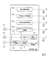
本実施形態のコンバインドサイクルプラントは、図1に示すように、ガスタービン10と、ガスタービン10から排気される燃焼ガスの排熱で蒸気を発生させる排熱回収ボイラー20と、排熱回収ボイラー20からの蒸気で駆動する高圧蒸気タービン(第一蒸気タービン)31、中圧蒸気タービン(第二蒸気タービン)32及び低圧蒸気タービン33と、各タービン10,31,32,33の駆動で発電する発電機34と、低圧蒸気タービン33から排気された蒸気を水に戻す復水器36と、復水器36から水を排熱回収ボイラー20に送る給水ポンプ37と、これらを制御する制御装置100と、を備えている。なお、以下の説明の都合上、高圧蒸気タービン31の定格圧力は12MPaで、中圧蒸気タービン32の定格圧力は4MPaで、低圧蒸気タービン33の定格圧力は1MPaであるとする。
As shown in FIG. 1, the combined cycle plant of the present embodiment includes a
ガスタービン10は、外気を圧縮して圧縮空気を生成する圧縮機11と、燃料ガスに圧縮空気を混合して燃焼させ高温の燃焼ガスを生成する燃焼器12と、燃焼ガスにより駆動するタービン13と、燃焼器12に供給する燃料流量を調節する燃料流量調節弁76と、を備えている。
The
ガスタービン10の燃焼器12には、燃料供給源からの燃料を燃焼器12に供給する燃料ラインが接続されている。この燃料ラインには、前述の燃料流量調節弁76が設けられている。ガスタービン10のタービン13は、その排気口が排熱回収ボイラー20と接続されている。
A fuel line that supplies fuel from a fuel supply source to the
圧縮機11の圧縮機ロータとタービン13のタービンロータとは、同一の軸線上に位置に互いに連結されて、ガスタービンロータとして一体回転する。また、本実施形態では、このガスタービンロータと、高圧蒸気タービン31のタービンロータと、中圧蒸気タービン32のタービンロータと、低圧蒸気タービン33のタービンロータと、発電機34の発電機ロータとが、同一軸線上に位置し互いに連結されて、一体回転する。よって、本実施形態のコンバインドサイクルプラントは、一軸式のコンバインドサイクルプラントである。
The compressor rotor of the
排熱回収ボイラー20は、高圧蒸気タービン31に供給する高圧蒸気(第一蒸気)を発生する高圧蒸気発生部(第一蒸気発生部)21と、中圧蒸気タービン32に供給する中圧蒸気を発生する中圧蒸気発生部23と、低圧蒸気タービン33に供給する低圧蒸気を発生する低圧蒸気発生部27と、高圧蒸気タービン31から排気された蒸気を加熱する再熱部26と、を備えている。高圧蒸気発生部21は、蒸気を発生する高圧ドラム22aと、高圧ドラム22aで発生した蒸気を過熱する高圧過熱器22bと、を有する。中圧蒸気発生部23は、中圧蒸気を発生する中圧ドラム24aと、中圧ドラム24aで発生した中圧蒸気を過熱する中圧過熱器24bと、を有する。中圧ドラム24aには、中圧ドラム24a内の圧力P5を検知する中圧ドラム圧力計87が設けられている。低圧蒸気発生部27は、蒸気を発生する低圧ドラム28aと、低圧ドラム28aで発生した蒸気を過熱する低圧過熱器28bと、を有する。
The exhaust
排熱回収ボイラー20の高圧過熱器22bと高圧蒸気タービン31の蒸気入口とは、高圧過熱器22bからの高圧蒸気を高圧蒸気タービン31に導く主蒸気ライン(第一蒸気ライン)41で接続されている。高圧蒸気タービン31の蒸気出口と中圧蒸気タービン32の蒸気入口とは、高圧蒸気タービン31から排気された蒸気を排熱回収ボイラー20の再熱部26を経て中圧蒸気タービン32の蒸気入口に導く再熱蒸気ライン42で接続されている。ここで、再熱蒸気ライン42で、高圧蒸気タービン31の蒸気出口と再熱部26との間を再熱前蒸気ライン42aとし、再熱部26と中圧蒸気タービン32の蒸気入口との間を再熱後蒸気ライン42bとする。排熱回収ボイラー20の低圧過熱器28bと低圧蒸気タービン33の蒸気入口とは、低圧蒸気を低圧蒸気タービン33に導く低圧蒸気ライン43で接続されている。
The
中圧蒸気タービン32の蒸気出口と低圧蒸気タービン33の蒸気入口とは、中圧タービン排気ライン56で接続されている。低圧蒸気タービン33の蒸気出口には、復水器36が接続されている。この復水器36には、復水を排熱回収ボイラー20に導く給水ライン44が接続されている。この給水ライン44には、前述の給水ポンプ37が設けられている。
The steam outlet of the intermediate
排熱回収ボイラー20の中圧過熱器24bと再熱前蒸気ライン42aとは、中圧蒸気ライン55で接続されている。主蒸気ライン41と再熱前蒸気ライン42aとは、高圧タービンバイパスライン(第一バイパスライン)51で接続されている。再熱前蒸気ライン42aと復水器36とは、ベンチレータライン(第二バイパスライン)52で接続されている。なお、再熱前蒸気ライン42a中における高圧タービンバイパスライン51の接続位置は、ベンチレータライン52の接続位置よりも下流側(再熱部26側)である。また、再熱前蒸気ライン42a中における中圧蒸気ライン55の接続位置は、高圧タービンバイパスライン51の接続位置よりも下流側(再熱部26側)である。再熱後蒸気ライン42bと復水器36とは、中圧タービンバイパスライン53で接続され、低圧蒸気ライン43と復水器36とは、低圧タービンバイパスライン54で接続されている。
The
主蒸気ライン41で、高圧タービンバイパスライン51との接続位置よりも下流側(高圧蒸気タービン31側)には、高圧過熱器22bからの高圧蒸気の圧力P2を検知する高圧蒸気圧力計81と、主蒸気止め弁61と、主蒸気加減弁62と、流入蒸気圧力計82とが、下流側に向かってこの順序で設けられている。高圧蒸気圧力計81は、高圧過熱器22bから高圧蒸気の圧力であって主蒸気止め弁61よりも上流側(高圧蒸気発生部21側)の圧力P2を検知する。流入蒸気圧力計82は、高圧蒸気の圧力であって、主蒸気加減弁62よりも下流側の圧力P1を検知する。すなわち、流入蒸気圧力計82は、高圧蒸気タービン31に流入する直前の高圧蒸気の圧力P1を検知する。
A high-pressure
高圧蒸気タービン31の第一段静翼環には、この第一段静翼環(蒸気接触部)の温度を検知する温度計83が設けられている。
The first stage stationary blade ring of the high-
高圧タービンバイパスライン51には、高圧タービンバイパス弁68と減温器69とが設けられている。中圧蒸気ライン55には、中圧ドラム24a内の圧力を調節する中圧ドラム圧力調節弁74と、再熱前蒸気ライン42aからの蒸気が中圧ドラム24aに流入するのを防ぐ逆止弁75が設けられている。
The high pressure
再熱前蒸気ライン42aで、ベンチレータライン52との接続位置よりも下流側(再熱部26側)には、逆止弁63が設けられている。この逆止弁63は、高圧タービンバイパスライン51や中圧蒸気ライン55を経て再熱前蒸気ライン42aに流入した蒸気が高圧蒸気タービン31に流入するのを防ぐ。ベンチレータライン52には、ベンチレータ弁71が設けられている。
In the
再熱後蒸気ライン42bで中圧タービンバイパスライン53との接続位置よりも下流側(中圧蒸気タービン32側)には、再熱蒸気圧力計84、再熱蒸気止め弁64、及び再熱蒸気加減弁65が、下流側に向かってこの順序で設けられている。中圧タービンバイパスライン53には、中圧タービンバイパス弁72が設けられている。
A reheat
低圧蒸気ライン43の低圧タービンバイパスライン54との接続位置よりも下流側(低圧蒸気タービン33側)には、低圧蒸気圧力計85、低圧蒸気止め弁66、及び低圧蒸気加減弁67が、下流側に向かってこの順序で設けられている。低圧タービンバイパスライン54には、低圧タービンバイパス弁73が設けられている。
A low-pressure
制御装置100は、図2に示すように、燃料流量調節弁76の動作を制御する燃料流量制御器101と、主蒸気止め弁61の動作を制御する主蒸気止め弁制御器102と、主蒸気加減弁62の動作を制御する主蒸気加減弁制御器103と、高圧タービンバイパス弁68の動作を制御する高圧タービンバイパス弁制御器104と、ベンチレータ弁71の動作を制御するベンチレータ弁制御器110と、を有する。制御装置100は、以上の他、再熱蒸気止め弁64、再熱蒸気加減弁65、低圧蒸気止め弁66、低圧蒸気加減弁67、中圧タービンバイパス弁72、低圧タービンバイパス弁73、中圧ドラム圧力調節弁74の動作を制御する制御器等も有している。
As shown in FIG. 2, the
ベンチレータ弁制御器110は、流入蒸気圧力計82で検知された高圧蒸気の圧力P1がしきい値になったか否かを判断する判断部111と、判断部111により高圧蒸気の圧力P1がしきい値になったと判断されるとベンチレータ弁71に対して閉指令を出力する指令出力部112と、温度計83で検知された高圧蒸気タービン31の温度で排熱回収ボイラー20の起動モードを認識する起動モード認識部113と、起動モード認識部113が認識した起動モードに応じて判断部111におけるしきい値を変更するしきい値変更部114と、を有する。
The
排熱回収ボイラー20の起動モードとしては、例えば、高圧蒸気タービン31の温度が高い状態からの起動であるホットモードと、高圧蒸気タービン31の温度が低い状態からの起動であるコールドモードとがある。起動モード認識部113は、高圧蒸気タービン31に蒸気を通気する直前に、温度計83で検知された高圧蒸気タービン31の温度が例えば400℃以上の場合、ホットモードであると認識する。また、起動モード認識部113は、高圧蒸気タービン31に蒸気を通気する直前に、温度計83で検知された高圧蒸気タービン31の温度が例えば400℃未満の場合、コールドモードであると認識する。
Examples of the startup mode of the exhaust
なお、本実施形態の制御装置100は、コンピュータで構成されており、制御装置100の各部の処理は、いずれも、ハードディスクドライブ装置等の外部記憶装置やメモリ等の記憶装置と、この記憶装置に記憶されているプログラムを実行するCPUとを有して構成されている。
Note that the
次に、本実施形態のコンバインドサイクルプラントの起動過程における動作について説明する。 Next, the operation | movement in the starting process of the combined cycle plant of this embodiment is demonstrated.
制御装置100が外部から起動指令を受け付けると、図示されていない起動装置に対して起動指令を出力し、この起動装置を起動させる。この起動装置の起動により、ガスタービン10の圧縮機ロータ及びタービンロータが回転し始める。圧縮機ロータが回転すると、圧縮機11からの圧縮空気が燃焼器12に供給され始められる。圧縮機ロータ及びタービンロータが例えば予め定められた回転数になると、燃料流量制御器101は、燃料流量調節弁76に対して開指令を出力する。この結果、燃料ラインからの燃料が燃料流量調節弁76を介して燃焼器12に供給され始められる。この燃料は、圧縮機11から燃焼器12に供給された圧縮空気中で燃焼する。燃焼器12で発生した燃焼ガスは、タービン13に流れ込み、タービンロータを回転させる。
When the
燃料流量制御器101は、ガスタービン10の起動過程では、燃料流量調節弁76が時間経過に伴って次第に開く予め定められたパターンに従った開度を示す開指令を出力する。このため、燃焼器12に供給される燃料の流量も次第に増加し、図3に示すように、タービンロータの回転数も次第に増加する。タービンロータが予め定められた回転数になると、起動装置によるタービンロータの回転補助が停止される。その後、タービンロータの回転数が定格回転数、例えば、3600rpmになると、発電機34が系統電力線に接続され、タービンロータ及び発電機34ロータの回転数は、この定格回転数に維持される。
In the starting process of the
タービン13を通過した燃焼ガスは、排気ガスとして排熱回収ボイラー20に送られる。排熱回収ボイラー20の各蒸気発生部21,23,27では、排熱回収ボイラー20を流れる排気ガスと水とを熱交換させて、水を加熱し蒸気にする。高圧蒸気発生部21で発生した高圧蒸気は、主蒸気ライン41に流入する。中圧蒸気発生部23で発生した中圧蒸気は中圧蒸気ライン55に流入する。低圧蒸気発生部27で発生した低圧蒸気は、低圧蒸気ライン43に流入する。
The combustion gas that has passed through the
排熱回収ボイラー20から蒸気が発生し始める前、主蒸気止め弁61、主蒸気加減弁62、再熱蒸気止め弁64、再熱蒸気加減弁65、低圧蒸気止め弁66、低圧蒸気加減弁67、高圧タービンバイパス弁68、中圧タービンバイパス弁72、低圧タービンバイパス弁73、中圧ドラム圧力調節弁74は、いずれも、閉状態である。一方、ベンチレータ弁71は、排熱回収ボイラー20から蒸気が発生し始める前、開状態である。
Before the steam starts to be generated from the exhaust
低圧タービンバイパス弁73は、プラントの起動過程で、低圧蒸気ライン43の圧力P4が例えば低圧蒸気タービン33の定格圧力1MPaよりも低い0.5MPaに維持されるよう、制御装置100により制御される。このため、低圧蒸気圧力計85で検知される低圧蒸気の圧力P4が0.5MPaになるまで、低圧タービンバイパス弁73は閉じている。低圧蒸気発生部27での低圧蒸気の発生量が増加し、低圧蒸気ライン43の圧力P4が0.5MPa以上になると、低圧タービンバイパス弁73が開き、低圧蒸気発生部27からの低圧蒸気が低圧タービンバイパスライン54を介して復水器36に流入するようになる。
The low-pressure
制御装置100は、中圧ドラム24aが予め定められた圧力、例えば、中圧蒸気タービン32の定格圧力4MPaよりもいくらか高い圧力に維持されるよう、中圧ドラム圧力調節弁74を制御する。よって、中圧ドラム24a内の圧力が維持すべき圧力以上になると、中圧ドラム圧力調節弁74が開き、中圧ドラム24aで発生した中圧蒸気が中圧蒸気ライン55を介して、再熱前蒸気ライン42aに流れ込むようになる。
The
中圧タービンバイパス弁72は、プラントの起動過程で、再熱後蒸気ライン42bの圧力P3が例えば中圧蒸気タービン32の定格圧力4MPaよりも低い2MPaに維持されるよう、制御装置100により制御される。このため、再熱蒸気圧力計84で検知される再熱(中圧)蒸気の圧力P3が2MPaになるまで、中圧タービンバイパス弁72は閉じている。中圧蒸気発生部23での中圧蒸気の発生量や高圧タービンバイパスライン51を経てきた蒸気等の流量が増加し、再熱後蒸気ライン42bの圧力P3が2.0MPa以上になると、中圧タービンバイパス弁72が開き、再熱後蒸気ライン42bを流れる蒸気が中圧タービンバイパスライン53を介して復水器36に流入するようになる。
The intermediate pressure
高圧タービンバイパス弁68は、プラントの起動過程で、主蒸気ライン41の圧力P2が例えば高圧蒸気タービン31の定格圧力12MPaよりも低い5MPaに維持されるよう、制御装置100の高圧タービンバイパス弁制御器104により制御される。このため、高圧蒸気圧力計81で検知される高圧蒸気の圧力P2が5MPaになるまで、図3に示すように、高圧タービンバイパス弁68は閉じている。高圧蒸気発生部21での高圧蒸気の発生量が増加し、主蒸気ライン41の圧力P2が5MPa以上になると、高圧タービンバイパス弁68が開き、高圧蒸気発生部21からの高圧蒸気が高圧タービンバイパスライン51を介して再熱蒸気ライン42に流入するようになる。
The high-pressure
制御装置100は、プラントの起動過程で、各蒸気タービン31,32,33に供給する蒸気の供給開始条件が成立したことを認識すると、各蒸気タービン31,32,33の蒸気止め弁61,64,66及び蒸気加減弁62,65,67を開ける。蒸気の供給開始条件としては、例えば、高圧蒸気タービン31に設けられている温度計83で検知された温度が予め定められた温度になることである。この際、各蒸気加減弁62,65,67は、予め定められた開度パターンに従って徐々に開けられる。この結果、図3に示すように、各蒸気タービン31,32,33に蒸気が供給され始められ、蒸気タービン出力(高圧蒸気タービン31、中圧蒸気タービン32、低圧蒸気タービン33の合計出力)が徐々に増加する。
When the
なお、ここでは、蒸気の供給開始条件を、高圧蒸気タービン31に設けられている温度計83で検知された温度が予め定められた温度になることにしている。しかしながら、蒸気の供給開始条件を、高圧蒸気タービン31に設けられている温度計83で検知された温度が予め定められた温度になり、且つ中圧蒸気タービン32に設けられている温度計で検知された温度が予め定められた温度になることにしてもよい。
Here, the steam supply start condition is that the temperature detected by the
低圧蒸気止め弁66及び低圧蒸気加減弁67が開き、低圧蒸気タービン33に低圧蒸気が供給され始められると、低圧蒸気ライン43の圧力P4が低下する。そこで、制御装置100は、低圧蒸気ライン43の圧力P4を維持するため、低圧タービンバイパス弁73を徐々に閉じる。
When the low-pressure
再熱蒸気止め弁64及び再熱蒸気加減弁65が開き、中圧蒸気タービン32に蒸気が供給され始められると、再熱後蒸気ライン42bの圧力P3が低下する。そこで、制御装置100は、再熱後蒸気ライン42bの圧力P3を維持するため、中圧タービンバイパス弁72を徐々に閉じる。
When the reheat
主蒸気止め弁61及び主蒸気加減弁62が開き、高圧蒸気タービン31に高圧蒸気が供給され始められると、主蒸気ライン41の圧力P2が低下する。そこで、高圧タービンバイパス弁制御器104は、主蒸気ライン41の圧力P2を維持するため、図3に示すように、高圧タービンバイパス弁68を徐々に閉じる。
When the main
制御装置100は、その後、各蒸気タービン31,32,33に供給する蒸気について切替条件が成立したことを認識すると、各蒸気タービン31,32,33に蒸気を供給する蒸気ラインの維持圧力を変更する。具体的に、制御装置100は、低圧蒸気ライン43の圧力P4が例えば低圧蒸気タービン33の定格圧力1MPaよりも僅かに高い1.1MPaに維持されるよう、低圧タービンバイパス弁73を制御する。このため、上記切替条件が一旦満たされると、低圧蒸気ライン43の圧力P4が1.1MPa以上にならない限り、低圧タービンバイパス弁73は開かない。また、制御装置100は、上記切替条件が成立したと認識すると、再熱後蒸気ライン42bの圧力P3が例えば中圧蒸気タービン32の定格圧力4MPaよりも僅かに高い4.1MPaに維持されるよう、中圧タービンバイパス弁72を制御する。このため、上記切替条件が一旦満たされると、再熱後蒸気ライン42bの圧力P3が4.1MPa以上にならない限り、中圧タービンバイパス弁72は開かない。また、制御装置100の高圧タービンバイパス弁制御器104は、上記切替条件が成立したと認識すると、主蒸気ライン41の圧力P2が例えば高圧蒸気タービン31の定格圧力12MPaよりも僅かに高い12.1MPaに維持されるよう、高圧タービンバイパス弁68を制御する。このため、上記切替条件が一旦満たされると、主蒸気ライン41の圧力P2が12.1MPa以上にならない限り、高圧タービンバイパス弁68は開かない。
After recognizing that the switching condition is satisfied for the steam supplied to the
前述したように、主蒸気加減弁62が徐々に開き、高圧蒸気タービン31に高圧蒸気が徐々に供給されている過程では、高圧蒸気タービン31から排気される蒸気の温度が風損による上昇する。そこで、本実施形態では、高圧蒸気タービン31の起動過程では、図3に示すように、ベンチレータ弁71を開けておき、高圧蒸気タービン31から排気された蒸気をベンチレータライン52を介して復水器36に送るようにしている。このため、本実施形態では、高圧蒸気タービン31の蒸気入口での圧力と蒸気出口の圧力との圧力差が大きくなり、高圧蒸気タービン31内での蒸気の仕事量が多くなって、高圧蒸気タービン31から排気される蒸気の温度上昇を抑えることができる。
As described above, in the process in which the main
ベンチレータ弁71は、ベンチレータ弁制御器110の判断部111により、高圧蒸気タービン31に供給される高圧蒸気の流量が規定流量になったと判断されときに閉じる。具体的に、ベンチレータ弁制御器110の判断部111は、高圧蒸気タービン31に供給される高圧蒸気の流量が規定流量になったか否かを流入蒸気圧力計82で検知された圧力P1により判断する(判断工程)。高圧蒸気タービン31に供給される高圧蒸気の流量と流入蒸気圧力計82で検知される圧力P1とは、正の相関性をもつ。このため、流入蒸気圧力計82で検知される圧力P1で、高圧蒸気の流量に関する規定流量に対応する圧力をしきい値として定めておくことで、判断部111は、流入蒸気圧力計82で検知された圧力P1がしきい値になったか否かにより、高圧蒸気の流量が規定流量になったか否かを判断することができる。
The
このしきい値は、ベンチレータ弁制御器110のしきい値変更部114により、排熱回収ボイラー20の起動モードに応じて変更される。起動モード認識部113は、高圧蒸気タービン31に蒸気を通気される直前に、高圧蒸気タービン31に設けられている温度計83で検知された高圧蒸気タービン31の温度が例えば400℃以上の場合ホットモードであると認識し、温度計83で検知された高圧蒸気タービン31の温度が例えば400℃未満の場合コールドモードであると認識する(起動モード認識工程)。しきい値変更部114は、起動モード認識部113により認識された起動モードがホットモードである場合、しきい値を例えば4MPaに設定する。また、しきい値変更部114は、起動モード認識部113により認識された起動モードがコールドモードである場合、しきい値を例えば2MPaに設定する(しきい値変更工程)。
This threshold value is changed by the threshold
判断部111が、高圧蒸気タービン31に流入する高圧蒸気の流量が規定流量になった、つまり流入蒸気圧力計82で検知された圧力P1がしきい値になったと判断すると、ベンチレータ弁制御器110の指令出力部112がベンチレータ弁71に対して閉指令を出力する(指令出力工程)。この閉指令には、ベンチレータ弁71の単位時間当たりの開度変化量である開度変化率を予め定められた開度変化率にする内容も含まれている。ベンチレータ弁71は、この閉指令を受けると、予め定められた開度変化率で徐々に閉じられる。
When the
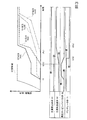
ここで、起動モードがホットモードの場合とコールドモードの場合とにおける各弁の動作タイミングの相違について、図3及び図4を用いて説明する。なお、図3は起動モードがホットモードの場合のタイミングチャートを示し、図4は起動モードがコールドモードの場合のタイミングチャートを示す。 Here, the difference in the operation timing of each valve when the activation mode is the hot mode and when the activation mode is the cold mode will be described with reference to FIGS. 3 and 4. 3 shows a timing chart when the activation mode is the hot mode, and FIG. 4 shows a timing chart when the activation mode is the cold mode.
ガスタービン10の出力が得られ始めるタイミングt1は、基本的に、ホットモードの場合とコールドモードの場合とで同じである。但し、ガスタービン10の出力が定格出力に至るまでの時間は、ホットモードの場合よりコールドモードの場合の方が長くなる。
The timing t1 at which the output of the
各蒸気タービン31,32,33の蒸気止め弁61,64,66及び蒸気加減弁62,65,67を開ける条件、つまり、各蒸気タービン31,32,33に供給する蒸気の供給開始条件は、ホットモードの場合とコールドモードの場合とで同じである。しかしながら、コールドモードの場合、ホットモードの場合よりも排熱回収ボイラー20に滞留している水の温度や各蒸気タービン31,32,33のメタル温度が低いため、各蒸気タービン31,32,33に供給する蒸気の供給開始条件が成立するタイミングがホットモードの場合のタイミングよりも遅くなる。よって、コールドモードの場合に各蒸気タービン31,32,33の蒸気止め弁61,64,66及び蒸気加減弁62,65,67が開くタイミング、さらに、蒸気タービン31,32,33の出力が得られ始めるタイミングt2(c)は、ホットモードの場合の同タイミングt2(h)より遅くなる。
The conditions for opening the
さらに、各蒸気タービン31,32,33の蒸気加減弁62,65,67の単位時間当たりの開度変化量である開度変化率が、ホットモードの場合よりもコールドモードの場合の方が小さい。言い換えると、ホットモードの場合よりもコールドモードの場合の方が、各蒸気タービン31,32,33の蒸気加減弁62,65,67はゆっくりと開く。このため、蒸気タービン31,32,33の出力は、ホットモードの場合よりもコールドモードの場合の方がゆっくりと増加する。
Furthermore, the rate of change in opening, which is the amount of change in opening per unit time of the
プラントの起動過程で、各蒸気ラインで維持すべき圧力は、ホットモードの場合とコールドモードの場合とで同じである。すなわち、プラントの起動過程では、ホットモードの場合でもコールドモードの場合でも、主蒸気ライン41の圧力P2が5MPaに維持されるように高圧タービンバイパス弁68が制御され、再熱後蒸気ライン42bの圧力P3が2MPaに維持されるように中圧タービンバイパス弁72が制御され、低圧蒸気ライン43の圧力P4が0.5MPaに維持されるように低圧タービンバイパス弁73が制御される。
During the start-up process of the plant, the pressure to be maintained in each steam line is the same in the hot mode and the cold mode. That is, in the start-up process of the plant, the high pressure
ホットモードでの起動過程では、高圧蒸気タービン31の第一段静翼環の温度が400℃以上である。このため、ホットモードでの起動過程では、ベンチレータ弁制御器110の起動モード認識部113は、起動モードがホットモードであると認識する。しきい値変更部114は、前述したように、起動モード認識部113により認識された起動モードがホットモードである場合、しきい値を例えば4MPaに設定する。よって、ホットモードでの起動過程では、流入蒸気圧力計82で検知される圧力P1が4MPaになると、判断部111は、高圧蒸気タービン31に流入する高圧蒸気の流量が規定流量になったと判断する。判断部111が規定流量になったと判断すると、ベンチレータ弁制御器110の指令出力部112がベンチレータ弁71に対して閉指令を出力する。ベンチレータ弁71は、図3に示しように、この閉指令を受けると、予め定められた開度変化率で閉じられる(t3(h))。
In the startup process in the hot mode, the temperature of the first stage stationary blade ring of the high-
また、コールドモードでの起動過程では、高圧蒸気タービン31の第一段静翼環の温度が400℃未満である。このため、コールドモードでの起動過程では、ベンチレータ弁制御器110の起動モード認識部113は、起動モードがコールドモードであると認識する。しきい値変更部114は、前述したように、起動モード認識部113により認識された起動モードがコールドモードである場合、しきい値を例えば2MPaに設定する。よって、コールドモードでの起動過程では、流入蒸気圧力計82で検知される圧力P1が2MPaになると、判断部111は、高圧蒸気タービン31に流入する高圧蒸気の流量が規定流量になったと判断する。判断部111が規定流量になったと判断すると、前述したように、ベンチレータ弁制御器110の指令出力部112がベンチレータ弁71に対して閉指令を出力する。ベンチレータ弁71は、図4に示すように、この閉指令を受けると、予め定められた開度変化率で閉じられる(t3(c))。
In the starting process in the cold mode, the temperature of the first stage stationary blade ring of the high-
仮に、本実施形態において、ホットモードの場合にベンチレータ弁71が閉じ始める直前の高圧蒸気発生部21における高圧蒸気の発生量が200t/hであるとする。さらに、この高圧蒸気のうち、高圧タービンバイパス弁68及び排熱回収ボイラー20の再熱部26を経て再熱後蒸気ライン42bに流入する高圧蒸気の流量が100t/hであり、ベンチレータ弁71を介して復水器36に流入する高圧蒸気の流量が100t/hであるとする。この場合、再熱後蒸気ライン42bに流れる蒸気の流量は、中圧蒸気発生部23で発生した中圧蒸気を無視すると、ベンチレータ弁71を閉じる前後で、100t/hから200t/hに変化する。
In the present embodiment, it is assumed that the amount of high-pressure steam generated in the high-
また、仮に、本実施形態において、コールドモードの場合にベンチレータ弁71が閉じ始める直前の高圧蒸気発生部21における高圧蒸気の発生量が150t/hであるとする。さらに、この高圧蒸気のうち、高圧タービンバイパス弁68及び排熱回収ボイラー20の再熱部26を経て再熱後蒸気ライン42bに流入する高圧蒸気の流量が100t/hであり、ベンチレータ弁71を介して復水器36に流入する高圧蒸気の流量が50t/hであるとする。この場合、再熱後蒸気ライン42bに流れる蒸気の流量は、前述と同様、中圧蒸気発生部23で発生した中圧蒸気を無視すると、ベンチレータ弁71を閉じる前後で、100t/hから150t/hに変化する。
In the present embodiment, it is assumed that the amount of high-pressure steam generated in the high-
ここで、比較例として、コールドモードの場合に、高圧蒸気タービン31に流入する高圧蒸気の流量が規定流量になったか否かを判断するしきい値が、ホットモードの場合と同じある例について説明する。この比較例においても、本実施形態のコールドモードの場合と同様、コールドモードの場合にベンチレータ弁71が閉じ始める直前の高圧蒸気発生部21における高圧蒸気の発生量が、150t/hであるとする。この比較例では、高圧蒸気タービン31に流入する高圧蒸気の流量が規定流量になったか否かを判断するしきい値(規定流量が100t/h相当の4MPa)が、コールドモードの場合でもホットモードの場合と同じであるため、ベンチレータ弁71が閉じ始める直前でベンチレータ弁71を介して復水器36に流入する高圧蒸気の流量が100t/hになる。言い換えると、図4に示すように、比較例でベンチレータ弁71を閉じるタイミングt3(cc)は、本実施形態でベンチレータ弁71を閉じるタイミングt3(c)よりも遅くなる。この結果、高圧蒸気発生部21における高圧蒸気の発生量のうち、高圧タービンバイパス弁68及び排熱回収ボイラー20の再熱部26を経て再熱後蒸気ライン42bに流入する高圧蒸気の流量が50t/h(=150t/h−100t/h)になる。よって、この比較例では、コールドモードの場合、再熱後蒸気ライン42bに流れる蒸気の流量は、中圧蒸気発生部23で発生した中圧蒸気を無視すると、ベンチレータ弁71を閉じる前後で、50t/hから150t/hに変化する。
Here, as a comparative example, an example in which the threshold value for determining whether or not the flow rate of the high-pressure steam flowing into the high-
従って、比較例でのコールドモードの場合は、本実施形態のコールドモード及びホットモードの場合よりも、ベンチレータ弁71を閉じる前後での再熱後蒸気ライン42bに流れる蒸気の流量変化率が大きくなる。このため、比較例でのコールドモードの場合、再熱蒸気ライン42に関する制御系、より具体的には、再熱後蒸気ライン42bを通る蒸気の状態量等に基づいて制御する制御系が不安定になる可能性が高くなる。
Therefore, in the case of the cold mode in the comparative example, the rate of change in the flow rate of the steam flowing through the
しかしながら、本実施形態では、以上で説明したように、高圧蒸気タービン31に流入する高圧蒸気の流量が規定流量になったか否かを判断するしきい値を、ホットモードの場合に4MPa(規定流量が100t/h相当)とし、コールドモードの場合に2MPa(規定流量が50t/h相当)にしている。このため、本実施形態では、コールドモードの場合でも、ベンチレータ弁71を閉じる前後での再熱後蒸気ライン42bに流れる蒸気の流量変化率をホットモードの場合と同様に比較的小さくすることができ、再熱蒸気ライン42に関する制御系が不安定になることを抑えることができる。
However, in the present embodiment, as described above, the threshold value for determining whether or not the flow rate of the high-pressure steam flowing into the high-
プラントの起動過程では、高圧蒸気発生部21からの高圧蒸気の温度とこの高圧蒸気の発生量とには、正の相関性がある。つまり、プラントの起動過程では、高圧蒸気発生部21からの高圧蒸気の温度が高くなると、この高圧蒸気の発生量が多くなり、高圧蒸気発生部21からの高圧蒸気の温度が低くなると、この高圧蒸気の発生量が少なくなる。また、プラントの起動過程では、高圧蒸気の温度が高くなると、高圧蒸気タービン31に供給する高圧蒸気の流量が多くなる。このため、プラントの起動過程では、高圧蒸気の温度と高圧蒸気タービン31へ供給する高圧蒸気の流量とには、正の相関性がある。発明者は、係る点に着目して、本実施形態において、判断部111が規定流量になったか否かを判断するしきい値を、高圧蒸気の温度に対して正の相関性を持たせて変更している。このため、本実施形態では、高圧蒸気発生部21からの高圧蒸気の発生量が少ないときには規定流量が小さくなり、ベンチレータ弁71の閉じる前後での再熱後蒸気ライン42bに流れる蒸気の流量変化率を小さくすることができる。
In the start-up process of the plant, there is a positive correlation between the temperature of the high-pressure steam from the high-
なお、以上の実施形態では、高圧蒸気タービン31に設けた温度計83で検知された温度に応じて、排熱回収ボイラー20の起動モードを認識している。しかしながら、今回のガスタービン10の起動が前回のガスタービン10の停止から予め定められた時間以内の場合に、排熱回収ボイラー20の起動モードがホットモードであると認識し、予め定められた時間を超える場合に、排熱回収ボイラー20の起動モードがコールドモードであると認識するようにしてもよい。
In the above embodiment, the activation mode of the exhaust
また、以上の実施形態では、排熱回収ボイラー20の起動モードに応じて、しきい値を変更している。しかしながら、図1中で想像線で示すように、主蒸気ライン41に温度計89を設け、この温度計89で検知される高圧蒸気の温度に応じて、しきい値を変更してもよい。この場合、高圧蒸気の温度が高いときにはしきい値を大きくし、高圧蒸気の温度が低いときにはしきい値を小さくする。すなわち、この場合、ベンチレータ弁制御器110は、排熱回収ボイラー20の起動モードを認識しない。
Moreover, in the above embodiment, the threshold value is changed according to the activation mode of the exhaust
また、以上では、しきい値として二つの値を採用しているが、三つ以上の値を採用してもよい。例えば、排熱回収ボイラー20の起動モードとして、高圧蒸気タービン31の温度が450℃以上のホットモードと、高圧蒸気タービン31の温度が450℃未満で350℃以上のウォームモードと、高圧蒸気タービン31の温度が350℃未満のコールドモードがある場合、ホットモードのときにしきい値として4MPa、ウォームモードのときのしきい値として3MPa、コールドモードのときのしきい値として2MPaを設定するようにしてもよい。
In the above, two values are employed as the threshold value, but three or more values may be employed. For example, the start mode of the waste
以上では、高圧蒸気タービン31に流入する高圧蒸気の特定の圧力を、判断部111が規定流量になったか否かを判断するしきい値にしている。しかしながら、高圧蒸気タービン31に流入する高圧蒸気の流量を検知する流量計を設け、この流量計で検知される特定の流量を、判断部111が規定流量になったか否かを判断するしきい値にしてもよい。
In the above, the specific pressure of the high-pressure steam flowing into the high-
また、以上では、ベンチレータ弁71に対する閉指令に、ベンチレータ弁71の単位時間当たりの開度変化量である開度変化率を予め定められた開度変化率にする内容が含まれている。そこで、この開度変化率に関しても、高圧蒸気の温度に対して正の相関性を持たせて変更してもよい。すなわち、高圧蒸気の温度が高い場合には、開度変化率を大きくし、高圧蒸気の温度が低い場合には、開度変化率を小さくしてもよい。
In the above description, the close command for the
また、本実施形態のコンバインドサイクルプラントは、高圧蒸気タービン31と中圧蒸気タービン32と低圧蒸気タービン33の3台の蒸気タービンを備えている。しかしながら、本実施形態の高圧蒸気タービン31に相当する第一蒸気タービンと本実施形態の中圧蒸気タービン32に相当する第二蒸気タービンとを備え、本実施形態の低圧蒸気タービン33に相当する蒸気タービンを備えていない場合でも、本発明を適用することができる。
In addition, the combined cycle plant of the present embodiment includes three steam turbines, a high-
10:ガスタービン、11:圧縮機、12:燃焼器、20:排熱回収ボイラー、21:高圧蒸気発生部(第一蒸気発生部)、23:中圧蒸気発生部、26:再熱部、27:低圧蒸気発生部、31:高圧蒸気タービン(第一蒸気タービン)、32:中圧蒸気タービン(第二蒸気タービン)、33:低圧蒸気タービン、34:発電機、36:復水器、41:主蒸気ライン(第一蒸気ライン)、42:再熱蒸気ライン、42a:再熱前蒸気ライン、42b:再熱後蒸気ライン、43:低圧蒸気ライン、44:給水ライン、51:高圧タービンバイパスライン(第一バイパスライン)、52:ベンチレータライン(第二バイパスライン)、53:中圧タービンバイパスライン、54:低圧タービンバイパスライン、61:主蒸気止め弁、62:主蒸気加減弁、64:再熱蒸気止め弁、65:再熱蒸気加減弁、66:低圧蒸気止め弁、67:低圧蒸気加減弁、68:高圧タービンバイパス弁、71:ベンチレータ弁、72:中圧タービンバイパス弁、73:低圧タービンバイパス弁、81:高圧蒸気圧力計、82:流入蒸気圧力計、83,89:温度計、84:再熱蒸気圧力計、85:低圧蒸気圧力計、86:出力計、100:制御装置、110:ベンチレータ弁制御器、111:判断部、112:指令出力部、113:起動モード認識部、114:しきい値変更部 10: Gas turbine, 11: Compressor, 12: Combustor, 20: Exhaust heat recovery boiler, 21: High-pressure steam generator (first steam generator), 23: Medium-pressure steam generator, 26: Reheat section, 27: Low-pressure steam generator, 31: High-pressure steam turbine (first steam turbine), 32: Medium-pressure steam turbine (second steam turbine), 33: Low-pressure steam turbine, 34: Generator, 36: Condenser, 41 : Main steam line (first steam line), 42: reheat steam line, 42a: steam line before reheat, 42b: steam line after reheat, 43: low pressure steam line, 44: feed water line, 51: high pressure turbine bypass Line (first bypass line), 52: ventilator line (second bypass line), 53: medium pressure turbine bypass line, 54: low pressure turbine bypass line, 61: main steam stop valve, 62: main steam control valve, 4: Reheat steam stop valve, 65: Reheat steam control valve, 66: Low pressure steam stop valve, 67: Low pressure steam control valve, 68: High pressure turbine bypass valve, 71: Ventilator valve, 72: Medium pressure turbine bypass valve, 73: Low pressure turbine bypass valve, 81: High pressure steam pressure gauge, 82: Inflow steam pressure gauge, 83, 89: Thermometer, 84: Reheat steam pressure gauge, 85: Low pressure steam pressure gauge, 86: Output gauge, 100: Control device, 110: ventilator valve controller, 111: determination unit, 112: command output unit, 113: activation mode recognition unit, 114: threshold change unit
Claims (11)
前記排熱回収ボイラーは、前記燃焼ガスの熱により前記第一蒸気タービンに供給する第一蒸気を発生する第一蒸気発生部と、前記第一蒸気タービンから排気された蒸気を加熱する再熱部と、を有し、
前記排熱回収ボイラーの前記第一蒸気発生部と前記第一蒸気タービンとは、前記第一蒸気を前記第一蒸気タービンに導く第一蒸気ラインで接続され、
前記第一蒸気タービンと前記第二蒸気タービンとは、前記第一蒸気タービンから排気された蒸気を前記排熱回収ボイラーの前記再熱部を経て前記第二蒸気タービンに導く再熱蒸気ラインで接続され、
前記再熱蒸気ライン中で前記第一蒸気タービンから前記再熱部までの再熱前蒸気ラインと前記第一蒸気ラインとは、第一バイパスラインで接続され、
前記再熱前蒸気ラインと前記復水器とは、第二バイパスラインで接続され、
前記第二バイパスラインには、前記第二バイパスラインを通る蒸気の流量を調節するベンチレータ弁が設けられているコンバインドサイクルプラントの制御装置において、
前記第一蒸気タービン及び前記第二蒸気タービンの起動過程で、前記第一蒸気タービンに流入する前記第一蒸気の流量が規定流量になったか否かを設定されたしきい値から判断する判断部と、
前記判断部により、前記第一蒸気タービンに流入する前記第一蒸気の流量が規定流量になったと判断されると、開状態の前記ベンチレータ弁に対して閉状態への移行を示す閉指令を出力する指令出力部と、
前記排熱回収ボイラーの起動モードにおけるモードの種類に応じて前記しきい値を変更するしきい値変更部と、
を有する制御装置。 A gas turbine driven by combustion gas, an exhaust heat recovery boiler that generates steam by heat of the combustion gas exhausted from the gas turbine, first and second steam turbines driven by the steam, and the second steam turbine A condenser for returning the steam exhausted from the water to the water,
The exhaust heat recovery boiler includes a first steam generating unit that generates first steam to be supplied to the first steam turbine by heat of the combustion gas, and a reheating unit that heats steam exhausted from the first steam turbine. And having
The first steam generation part of the exhaust heat recovery boiler and the first steam turbine are connected by a first steam line that guides the first steam to the first steam turbine,
The first steam turbine and the second steam turbine are connected by a reheat steam line that guides the steam exhausted from the first steam turbine to the second steam turbine through the reheat portion of the exhaust heat recovery boiler. And
In the reheat steam line, the pre-reheat steam line from the first steam turbine to the reheat section and the first steam line are connected by a first bypass line,
The pre-reheat steam line and the condenser are connected by a second bypass line,
In the control apparatus for the combined cycle plant, the second bypass line is provided with a ventilator valve that adjusts the flow rate of steam passing through the second bypass line.
A determination unit that determines whether or not the flow rate of the first steam flowing into the first steam turbine has reached a specified flow rate in the starting process of the first steam turbine and the second steam turbine from a set threshold value. When,
When the determination unit determines that the flow rate of the first steam flowing into the first steam turbine has reached a specified flow rate, a closing command indicating the transition to the closed state is output to the ventilator valve in the open state Command output unit to
A threshold value changing unit for changing the threshold value according to the mode type in the startup mode of the exhaust heat recovery boiler;
Control device.
前記しきい値は、前記第一蒸気タービンに流入する前記第一蒸気の圧力に関する値である、
制御装置。 The control device according to claim 1,
The threshold is a value related to the pressure of the first steam flowing into the first steam turbine.
Control device.
前記しきい値は、前記第一蒸気タービンに流入する前記第一蒸気の規定流量に対応する前記第一蒸気の圧力である、
制御装置。 The control device according to claim 1,
The threshold value is a pressure of the first steam corresponding to a specified flow rate of the first steam flowing into the first steam turbine.
Control device.
更に、前記排熱回収ボイラーの前記起動モードが少なくともコールドモードであるかホットモードであるかを認識する起動モード認識部を有し、
前記しきい値変更部は、前記起動モード認識部が認識したモードの種類に応じて、前記しきい値を変更する、
制御装置。 In the control device according to any one of claims 1 to 3,
And a start mode recognition unit for recognizing whether the start mode of the exhaust heat recovery boiler is at least a cold mode or a hot mode,
The threshold value changing unit changes the threshold value according to the type of mode recognized by the activation mode recognition unit.
Control device.
前記起動モード認識部は、温度計で検知された前記第一蒸気タービンにおける蒸気接触部の温度に応じて前記起動モードの種類を認識する、
制御装置。 The control device according to claim 4,
The activation mode recognition unit recognizes the type of the activation mode according to the temperature of the steam contact portion in the first steam turbine detected by a thermometer.
Control device.
前記ガスタービンと、前記排熱回収ボイラーと、前記第一蒸気タービンと、前記第二蒸気タービンと、前記復水器と、を備えている、
コンバインドサイクルプラント。 A control device according to any one of claims 1 to 5;
The gas turbine, the exhaust heat recovery boiler, the first steam turbine, the second steam turbine, and the condenser.
Combined cycle plant.
前記排熱回収ボイラーは、前記燃焼ガスの熱により前記第一蒸気タービンに供給する第一蒸気を発生する第一蒸気発生部と、前記第一蒸気タービンから排気された蒸気を加熱する再熱部と、を有し、
前記排熱回収ボイラーの前記第一蒸気発生部と前記第一蒸気タービンとは、前記第一蒸気を前記第一蒸気タービンに導く第一蒸気ラインで接続され、
前記第一蒸気タービンと前記第二蒸気タービンとは、前記第一蒸気タービンから排気された蒸気を前記排熱回収ボイラーの前記再熱部を経て前記第二蒸気タービンに導く再熱蒸気ラインで接続され、
前記再熱蒸気ライン中で前記第一蒸気タービンから前記再熱部までの再熱前蒸気ラインと前記第一蒸気ラインとは、第一バイパスラインで接続され、
前記再熱前蒸気ラインと前記復水器とは、第二バイパスラインで接続され、
前記第二バイパスラインには、前記第二バイパスラインを通る蒸気の流量を調節するベンチレータ弁が設けられているコンバインドサイクルプラントの制御方法において、
前記第一蒸気タービン及び前記第二蒸気タービンの起動過程で、前記第一蒸気タービンに流入する前記第一蒸気の流量が規定流量になったか否かを設定されたしきい値から判断する判断工程と、
前記判断工程で、前記第一蒸気タービンに流入する前記第一蒸気の流量が規定流量になったと判断されると、開状態の前記ベンチレータ弁に対して閉状態への移行を示す閉指令を出力する指令出力工程と、
前記排熱回収ボイラーの起動モードにおけるモードの種類に応じて前記しきい値を変更するしきい値変更工程と、
を実行するコンバインドサイクルプラントの制御方法。 A gas turbine driven by combustion gas, an exhaust heat recovery boiler that generates steam by heat of the combustion gas exhausted from the gas turbine, first and second steam turbines driven by the steam, and the second steam turbine A condenser for returning the steam exhausted from the water to the water,
The exhaust heat recovery boiler includes a first steam generating unit that generates first steam to be supplied to the first steam turbine by heat of the combustion gas, and a reheating unit that heats steam exhausted from the first steam turbine. And having
The first steam generation part of the exhaust heat recovery boiler and the first steam turbine are connected by a first steam line that guides the first steam to the first steam turbine,
The first steam turbine and the second steam turbine are connected by a reheat steam line that guides the steam exhausted from the first steam turbine to the second steam turbine through the reheat portion of the exhaust heat recovery boiler. And
In the reheat steam line, the pre-reheat steam line from the first steam turbine to the reheat section and the first steam line are connected by a first bypass line,
The pre-reheat steam line and the condenser are connected by a second bypass line,
In the control method of the combined cycle plant, the second bypass line is provided with a ventilator valve that adjusts the flow rate of the steam passing through the second bypass line.
Wherein a first steam turbine and start the process of the second steam turbine, step determines the flow rate of the first steam is determined from a set whether it is prescribed rate threshold that flows into the first steam turbine When,
When it is determined in the determining step that the flow rate of the first steam flowing into the first steam turbine has become a specified flow rate, a close command indicating a transition to the closed state is output to the ventilator valve in the open state Command output process to perform,
A threshold value changing step of changing the threshold value according to the mode type in the startup mode of the exhaust heat recovery boiler;
The control method of the combined cycle plant that executes.
前記しきい値は、前記第一蒸気タービンに流入する前記第一蒸気の圧力に関する値である、
コンバインドサイクルプラントの制御方法。 In the control method of the combined cycle plant according to claim 7,
The threshold is a value related to the pressure of the first steam flowing into the first steam turbine.
Control method for combined cycle plant.
前記しきい値は、前記第一蒸気タービンに流入する前記第一蒸気の規定流量に対応する前記第一蒸気の圧力である、
コンバインドサイクルプラントの制御方法。 In the control method of the combined cycle plant according to claim 7,
The threshold value is a pressure of the first steam corresponding to a specified flow rate of the first steam flowing into the first steam turbine.
Control method for combined cycle plant.
更に、前記排熱回収ボイラーの前記起動モードが少なくともコールドモードであるかホットモードであるかを認識する起動モード認識工程を実行し、
前記しきい値変更工程では、前記起動モード認識工程で認識されたモードの種類に応じて、前記しきい値を変更する、
コンバインドサイクルプラントの制御方法。 In the control method of the combined cycle plant in any one of Claims 7-9,
Furthermore, an activation mode recognition step for recognizing whether the activation mode of the exhaust heat recovery boiler is at least a cold mode or a hot mode is performed,
In the threshold value changing step, the threshold value is changed according to the mode type recognized in the activation mode recognition step.
Control method for combined cycle plant.
前記起動モード認識工程では、温度計で検知された前記第一蒸気タービンにおける蒸気接触部の温度に応じて前記起動モードの種類を認識する、
コンバインドサイクルプラントの制御方法。 In the control method of the combined cycle plant according to claim 10,
In the activation mode recognition step, the type of the activation mode is recognized according to the temperature of the steam contact portion in the first steam turbine detected by a thermometer.
Control method for combined cycle plant.
Priority Applications (7)
| Application Number | Priority Date | Filing Date | Title |
|---|---|---|---|
| JP2014058967A JP6264128B2 (en) | 2014-03-20 | 2014-03-20 | Combined cycle plant, control method thereof, and control device thereof |
| PCT/JP2015/056182 WO2015141458A1 (en) | 2014-03-20 | 2015-03-03 | Combined cycle plant, method for controlling same, and device for controlling same |
| CN201580007854.5A CN105980668B (en) | 2014-03-20 | 2015-03-03 | Combined cycle unit, its control method and its control device |
| KR1020177024497A KR20170103991A (en) | 2014-03-20 | 2015-03-03 | Combined cycle plant, method for controlling same, and device for controlling same |
| DE112015001364.4T DE112015001364B4 (en) | 2014-03-20 | 2015-03-03 | Combined system, method for controlling the same and device for controlling the same |
| US15/116,079 US10287921B2 (en) | 2014-03-20 | 2015-03-03 | Combined cycle plant, method for controlling same, and device for controlling same |
| KR1020167022110A KR102051279B1 (en) | 2014-03-20 | 2015-03-03 | Combined cycle plant, method for controlling same, and device for controlling same |
Applications Claiming Priority (1)
| Application Number | Priority Date | Filing Date | Title |
|---|---|---|---|
| JP2014058967A JP6264128B2 (en) | 2014-03-20 | 2014-03-20 | Combined cycle plant, control method thereof, and control device thereof |
Publications (3)
| Publication Number | Publication Date |
|---|---|
| JP2015183536A JP2015183536A (en) | 2015-10-22 |
| JP2015183536A5 JP2015183536A5 (en) | 2017-01-19 |
| JP6264128B2 true JP6264128B2 (en) | 2018-01-24 |
Family
ID=54144433
Family Applications (1)
| Application Number | Title | Priority Date | Filing Date |
|---|---|---|---|
| JP2014058967A Active JP6264128B2 (en) | 2014-03-20 | 2014-03-20 | Combined cycle plant, control method thereof, and control device thereof |
Country Status (6)
| Country | Link |
|---|---|
| US (1) | US10287921B2 (en) |
| JP (1) | JP6264128B2 (en) |
| KR (2) | KR102051279B1 (en) |
| CN (1) | CN105980668B (en) |
| DE (1) | DE112015001364B4 (en) |
| WO (1) | WO2015141458A1 (en) |
Families Citing this family (6)
| Publication number | Priority date | Publication date | Assignee | Title |
|---|---|---|---|---|
| JP6732640B2 (en) * | 2016-11-18 | 2020-07-29 | 株式会社東芝 | Turbine controller |
| JP6845675B2 (en) * | 2016-12-08 | 2021-03-24 | 川崎重工業株式会社 | Raw material gas liquefier and its control method |
| KR20190016734A (en) * | 2017-08-09 | 2019-02-19 | 두산중공업 주식회사 | Power generation plant and control method thereof |
| CN110821587A (en) * | 2019-11-22 | 2020-02-21 | 润电能源科学技术有限公司 | Cylinder cutting method, device and equipment |
| CN113202570B (en) * | 2021-04-20 | 2023-04-18 | 华能苏州热电有限责任公司 | Cold-state starting method and equipment for gas-steam combined cycle unit |
| CN114941552B (en) * | 2022-05-13 | 2023-05-23 | 华电电力科学研究院有限公司 | Large supercritical reheating type double-pumping back pressure unit-based rapid switching control method for heat supply without stopping furnace when shutdown |
Family Cites Families (17)
| Publication number | Priority date | Publication date | Assignee | Title |
|---|---|---|---|---|
| US4184324A (en) * | 1975-04-02 | 1980-01-22 | Westinghouse Electric Corp. | Combined cycle electric power plant with coordinated plural feedback turbine control |
| JPS60228711A (en) * | 1984-04-25 | 1985-11-14 | Hitachi Ltd | Turbine bypass control device for combined cycle electric power plant |
| JPS6198908A (en) * | 1984-10-19 | 1986-05-17 | Hitachi Ltd | Steam turbine device |
| JPS61237802A (en) * | 1985-04-12 | 1986-10-23 | Hitachi Ltd | Warming-up method for steam turbine |
| JP2528162B2 (en) | 1988-06-29 | 1996-08-28 | 株式会社日立製作所 | Low voltage turbine bypass controller |
| JPH06221112A (en) | 1993-01-25 | 1994-08-09 | Toshiba Corp | Turbine bypass valve control device |
| JPH07166814A (en) * | 1993-12-14 | 1995-06-27 | Toshiba Corp | Starting method for uniaxial combined cycle power generation plant |
| JP2003020905A (en) | 2001-07-06 | 2003-01-24 | Mitsubishi Heavy Ind Ltd | Operating system and operating method for reheating electric power plant |
| JP4503995B2 (en) | 2003-12-02 | 2010-07-14 | 株式会社東芝 | Reheat steam turbine plant and operation method thereof |
| JP2005344528A (en) | 2004-05-31 | 2005-12-15 | Toshiba Corp | Combined cycle power generating plant and method for starting the same |
| JP4657057B2 (en) | 2005-08-12 | 2011-03-23 | 株式会社日立製作所 | Reheat steam turbine plant |
| US7987675B2 (en) * | 2008-10-30 | 2011-08-02 | General Electric Company | Provision for rapid warming of steam piping of a power plant |
| US20100242430A1 (en) * | 2009-03-31 | 2010-09-30 | General Electric Company | Combined cycle power plant including a heat recovery steam generator |
| JP5675516B2 (en) | 2011-07-01 | 2015-02-25 | 三菱重工業株式会社 | Combined cycle power plant |
| JP5734117B2 (en) * | 2011-07-01 | 2015-06-10 | 三菱日立パワーシステムズ株式会社 | Combined cycle power plant and operation method thereof |
| JP5911128B2 (en) | 2011-11-16 | 2016-04-27 | 三菱日立パワーシステムズ株式会社 | Power supply time calculation system for combined power plant |
| CN103452611B (en) * | 2013-09-05 | 2015-04-22 | 上海电气电站设备有限公司 | Combined-cycle combined heat and power system |
-
2014
- 2014-03-20 JP JP2014058967A patent/JP6264128B2/en active Active
-
2015
- 2015-03-03 CN CN201580007854.5A patent/CN105980668B/en active Active
- 2015-03-03 KR KR1020167022110A patent/KR102051279B1/en active IP Right Grant
- 2015-03-03 KR KR1020177024497A patent/KR20170103991A/en active Application Filing
- 2015-03-03 US US15/116,079 patent/US10287921B2/en active Active
- 2015-03-03 WO PCT/JP2015/056182 patent/WO2015141458A1/en active Application Filing
- 2015-03-03 DE DE112015001364.4T patent/DE112015001364B4/en active Active
Also Published As
| Publication number | Publication date |
|---|---|
| KR102051279B1 (en) | 2019-12-03 |
| KR20160107312A (en) | 2016-09-13 |
| DE112015001364B4 (en) | 2018-10-25 |
| US20170152762A1 (en) | 2017-06-01 |
| KR20170103991A (en) | 2017-09-13 |
| US10287921B2 (en) | 2019-05-14 |
| WO2015141458A1 (en) | 2015-09-24 |
| CN105980668A (en) | 2016-09-28 |
| JP2015183536A (en) | 2015-10-22 |
| CN105980668B (en) | 2018-09-25 |
| DE112015001364T5 (en) | 2016-12-01 |
Similar Documents
| Publication | Publication Date | Title |
|---|---|---|
| JP6264128B2 (en) | Combined cycle plant, control method thereof, and control device thereof | |
| JP5221443B2 (en) | Method for starting single-shaft combined cycle power plant and single-shaft combined cycle power plant | |
| US9353650B2 (en) | Steam turbine plant and driving method thereof, including superheater, reheater, high-pressure turbine, intermediate-pressure turbine, low-pressure turbine, condenser, high-pressure turbine bypass pipe, low-pressure turbine bypass pipe, and branch pipe | |
| JP5227352B2 (en) | System and method for pre-warming a heat recovery steam generator and associated steam line | |
| JP2016075177A (en) | Gas turbine, combined cycle plant, and method of starting gas turbine | |
| JP2012167571A (en) | Uniaxial combined cycle power generation plant, and method of operating the same | |
| JP6071421B2 (en) | Combined cycle plant, method for stopping the same, and control device therefor | |
| JP4503995B2 (en) | Reheat steam turbine plant and operation method thereof | |
| JP2015183536A5 (en) | ||
| WO2016194742A1 (en) | Combined cycle plant, device for controlling said plant and method for starting up said plant | |
| JP5178575B2 (en) | Power plant water supply apparatus and control method | |
| JP5694112B2 (en) | Uniaxial combined cycle power plant and operation method thereof | |
| JP7003000B2 (en) | Plant controller, plant control method, and power plant | |
| TWI654366B (en) | Factory control unit, factory control method, and power plant | |
| JP5959454B2 (en) | Steam turbine system | |
| JP5812873B2 (en) | Combined cycle power plant | |
| JP6877216B2 (en) | Power generation system | |
| JP2020084947A (en) | Steam turbine equipment, starting method of steam turbine equipment, and combined cycle plant | |
| JP5289068B2 (en) | Steam turbine power plant | |
| KR101708991B1 (en) | Turbine system and operation method thereof | |
| WO2020255719A1 (en) | Power plant | |
| JP6625848B2 (en) | Steam control valve control device, power plant and steam control valve control method | |
| JP6600572B2 (en) | Plant control apparatus and plant control method | |
| JP2003343213A (en) | Combined plant constructed with closed steam cooling gas turbine | |
| JPH01285606A (en) | Method and device of starting 2-stage reheat type steam turbine plant |
Legal Events
| Date | Code | Title | Description |
|---|---|---|---|
| A521 | Request for written amendment filed |
Free format text: JAPANESE INTERMEDIATE CODE: A523 Effective date: 20161129 |
|
| A621 | Written request for application examination |
Free format text: JAPANESE INTERMEDIATE CODE: A621 Effective date: 20161129 |
|
| A521 | Request for written amendment filed |
Free format text: JAPANESE INTERMEDIATE CODE: A821 Effective date: 20161130 |
|
| A131 | Notification of reasons for refusal |
Free format text: JAPANESE INTERMEDIATE CODE: A131 Effective date: 20170815 |
|
| A521 | Request for written amendment filed |
Free format text: JAPANESE INTERMEDIATE CODE: A523 Effective date: 20171012 |
|
| A521 | Request for written amendment filed |
Free format text: JAPANESE INTERMEDIATE CODE: A821 Effective date: 20171013 |
|
| TRDD | Decision of grant or rejection written | ||
| A01 | Written decision to grant a patent or to grant a registration (utility model) |
Free format text: JAPANESE INTERMEDIATE CODE: A01 Effective date: 20171121 |
|
| A61 | First payment of annual fees (during grant procedure) |
Free format text: JAPANESE INTERMEDIATE CODE: A61 Effective date: 20171204 |
|
| R150 | Certificate of patent or registration of utility model |
Ref document number: 6264128 Country of ref document: JP Free format text: JAPANESE INTERMEDIATE CODE: R150 |
|
| S533 | Written request for registration of change of name |
Free format text: JAPANESE INTERMEDIATE CODE: R313533 |
|
| R350 | Written notification of registration of transfer |
Free format text: JAPANESE INTERMEDIATE CODE: R350 |