JP6845675B2 - Raw material gas liquefier and its control method - Google Patents
Raw material gas liquefier and its control method Download PDFInfo
- Publication number
- JP6845675B2 JP6845675B2 JP2016238535A JP2016238535A JP6845675B2 JP 6845675 B2 JP6845675 B2 JP 6845675B2 JP 2016238535 A JP2016238535 A JP 2016238535A JP 2016238535 A JP2016238535 A JP 2016238535A JP 6845675 B2 JP6845675 B2 JP 6845675B2
- Authority
- JP
- Japan
- Prior art keywords
- inflator
- rotation speed
- pressure
- raw material
- material gas
- Prior art date
- Legal status (The legal status is an assumption and is not a legal conclusion. Google has not performed a legal analysis and makes no representation as to the accuracy of the status listed.)
- Active
Links
- 239000002994 raw material Substances 0.000 title claims description 113
- 238000000034 method Methods 0.000 title claims description 29
- 239000003507 refrigerant Substances 0.000 claims description 135
- 239000007789 gas Substances 0.000 claims description 120
- IJGRMHOSHXDMSA-UHFFFAOYSA-N Atomic nitrogen Chemical compound N#N IJGRMHOSHXDMSA-UHFFFAOYSA-N 0.000 claims description 52
- 238000001816 cooling Methods 0.000 claims description 51
- 230000001133 acceleration Effects 0.000 claims description 41
- 230000008859 change Effects 0.000 claims description 22
- 229910052757 nitrogen Inorganic materials 0.000 claims description 22
- 239000007788 liquid Substances 0.000 claims description 21
- 230000004913 activation Effects 0.000 claims description 10
- 238000009835 boiling Methods 0.000 claims description 10
- 229910001873 dinitrogen Inorganic materials 0.000 claims description 8
- 230000020169 heat generation Effects 0.000 description 19
- 238000011144 upstream manufacturing Methods 0.000 description 9
- 238000010586 diagram Methods 0.000 description 8
- UFHFLCQGNIYNRP-UHFFFAOYSA-N Hydrogen Chemical compound [H][H] UFHFLCQGNIYNRP-UHFFFAOYSA-N 0.000 description 7
- 230000008569 process Effects 0.000 description 5
- 239000001257 hydrogen Substances 0.000 description 4
- 229910052739 hydrogen Inorganic materials 0.000 description 4
- 230000009467 reduction Effects 0.000 description 3
- 230000006866 deterioration Effects 0.000 description 2
- 239000001307 helium Substances 0.000 description 2
- 229910052734 helium Inorganic materials 0.000 description 2
- SWQJXJOGLNCZEY-UHFFFAOYSA-N helium atom Chemical compound [He] SWQJXJOGLNCZEY-UHFFFAOYSA-N 0.000 description 2
- 150000002431 hydrogen Chemical class 0.000 description 2
- 239000012535 impurity Substances 0.000 description 2
- 229910052754 neon Inorganic materials 0.000 description 2
- GKAOGPIIYCISHV-UHFFFAOYSA-N neon atom Chemical compound [Ne] GKAOGPIIYCISHV-UHFFFAOYSA-N 0.000 description 2
- 230000035939 shock Effects 0.000 description 2
- 239000000126 substance Substances 0.000 description 2
- 230000036962 time dependent Effects 0.000 description 2
- -1 and as a result Substances 0.000 description 1
- 239000002826 coolant Substances 0.000 description 1
- 230000006872 improvement Effects 0.000 description 1
Images


Classifications
-
- F—MECHANICAL ENGINEERING; LIGHTING; HEATING; WEAPONS; BLASTING
- F25—REFRIGERATION OR COOLING; COMBINED HEATING AND REFRIGERATION SYSTEMS; HEAT PUMP SYSTEMS; MANUFACTURE OR STORAGE OF ICE; LIQUEFACTION SOLIDIFICATION OF GASES
- F25B—REFRIGERATION MACHINES, PLANTS OR SYSTEMS; COMBINED HEATING AND REFRIGERATION SYSTEMS; HEAT PUMP SYSTEMS
- F25B1/00—Compression machines, plants or systems with non-reversible cycle
- F25B1/10—Compression machines, plants or systems with non-reversible cycle with multi-stage compression
-
- F—MECHANICAL ENGINEERING; LIGHTING; HEATING; WEAPONS; BLASTING
- F25—REFRIGERATION OR COOLING; COMBINED HEATING AND REFRIGERATION SYSTEMS; HEAT PUMP SYSTEMS; MANUFACTURE OR STORAGE OF ICE; LIQUEFACTION SOLIDIFICATION OF GASES
- F25B—REFRIGERATION MACHINES, PLANTS OR SYSTEMS; COMBINED HEATING AND REFRIGERATION SYSTEMS; HEAT PUMP SYSTEMS
- F25B9/00—Compression machines, plants or systems, in which the refrigerant is air or other gas of low boiling point
- F25B9/06—Compression machines, plants or systems, in which the refrigerant is air or other gas of low boiling point using expanders
-
- F—MECHANICAL ENGINEERING; LIGHTING; HEATING; WEAPONS; BLASTING
- F25—REFRIGERATION OR COOLING; COMBINED HEATING AND REFRIGERATION SYSTEMS; HEAT PUMP SYSTEMS; MANUFACTURE OR STORAGE OF ICE; LIQUEFACTION SOLIDIFICATION OF GASES
- F25J—LIQUEFACTION, SOLIDIFICATION OR SEPARATION OF GASES OR GASEOUS OR LIQUEFIED GASEOUS MIXTURES BY PRESSURE AND COLD TREATMENT OR BY BRINGING THEM INTO THE SUPERCRITICAL STATE
- F25J1/00—Processes or apparatus for liquefying or solidifying gases or gaseous mixtures
- F25J1/0002—Processes or apparatus for liquefying or solidifying gases or gaseous mixtures characterised by the fluid to be liquefied
- F25J1/0005—Light or noble gases
- F25J1/0007—Helium
-
- F—MECHANICAL ENGINEERING; LIGHTING; HEATING; WEAPONS; BLASTING
- F25—REFRIGERATION OR COOLING; COMBINED HEATING AND REFRIGERATION SYSTEMS; HEAT PUMP SYSTEMS; MANUFACTURE OR STORAGE OF ICE; LIQUEFACTION SOLIDIFICATION OF GASES
- F25J—LIQUEFACTION, SOLIDIFICATION OR SEPARATION OF GASES OR GASEOUS OR LIQUEFIED GASEOUS MIXTURES BY PRESSURE AND COLD TREATMENT OR BY BRINGING THEM INTO THE SUPERCRITICAL STATE
- F25J1/00—Processes or apparatus for liquefying or solidifying gases or gaseous mixtures
- F25J1/0002—Processes or apparatus for liquefying or solidifying gases or gaseous mixtures characterised by the fluid to be liquefied
- F25J1/0005—Light or noble gases
- F25J1/001—Hydrogen
-
- F—MECHANICAL ENGINEERING; LIGHTING; HEATING; WEAPONS; BLASTING
- F25—REFRIGERATION OR COOLING; COMBINED HEATING AND REFRIGERATION SYSTEMS; HEAT PUMP SYSTEMS; MANUFACTURE OR STORAGE OF ICE; LIQUEFACTION SOLIDIFICATION OF GASES
- F25J—LIQUEFACTION, SOLIDIFICATION OR SEPARATION OF GASES OR GASEOUS OR LIQUEFIED GASEOUS MIXTURES BY PRESSURE AND COLD TREATMENT OR BY BRINGING THEM INTO THE SUPERCRITICAL STATE
- F25J1/00—Processes or apparatus for liquefying or solidifying gases or gaseous mixtures
- F25J1/003—Processes or apparatus for liquefying or solidifying gases or gaseous mixtures characterised by the kind of cold generation within the liquefaction unit for compensating heat leaks and liquid production
- F25J1/0047—Processes or apparatus for liquefying or solidifying gases or gaseous mixtures characterised by the kind of cold generation within the liquefaction unit for compensating heat leaks and liquid production using an "external" refrigerant stream in a closed vapor compression cycle
- F25J1/005—Processes or apparatus for liquefying or solidifying gases or gaseous mixtures characterised by the kind of cold generation within the liquefaction unit for compensating heat leaks and liquid production using an "external" refrigerant stream in a closed vapor compression cycle by expansion of a gaseous refrigerant stream with extraction of work
-
- F—MECHANICAL ENGINEERING; LIGHTING; HEATING; WEAPONS; BLASTING
- F25—REFRIGERATION OR COOLING; COMBINED HEATING AND REFRIGERATION SYSTEMS; HEAT PUMP SYSTEMS; MANUFACTURE OR STORAGE OF ICE; LIQUEFACTION SOLIDIFICATION OF GASES
- F25J—LIQUEFACTION, SOLIDIFICATION OR SEPARATION OF GASES OR GASEOUS OR LIQUEFIED GASEOUS MIXTURES BY PRESSURE AND COLD TREATMENT OR BY BRINGING THEM INTO THE SUPERCRITICAL STATE
- F25J1/00—Processes or apparatus for liquefying or solidifying gases or gaseous mixtures
- F25J1/003—Processes or apparatus for liquefying or solidifying gases or gaseous mixtures characterised by the kind of cold generation within the liquefaction unit for compensating heat leaks and liquid production
- F25J1/0047—Processes or apparatus for liquefying or solidifying gases or gaseous mixtures characterised by the kind of cold generation within the liquefaction unit for compensating heat leaks and liquid production using an "external" refrigerant stream in a closed vapor compression cycle
- F25J1/0052—Processes or apparatus for liquefying or solidifying gases or gaseous mixtures characterised by the kind of cold generation within the liquefaction unit for compensating heat leaks and liquid production using an "external" refrigerant stream in a closed vapor compression cycle by vaporising a liquid refrigerant stream
-
- F—MECHANICAL ENGINEERING; LIGHTING; HEATING; WEAPONS; BLASTING
- F25—REFRIGERATION OR COOLING; COMBINED HEATING AND REFRIGERATION SYSTEMS; HEAT PUMP SYSTEMS; MANUFACTURE OR STORAGE OF ICE; LIQUEFACTION SOLIDIFICATION OF GASES
- F25J—LIQUEFACTION, SOLIDIFICATION OR SEPARATION OF GASES OR GASEOUS OR LIQUEFIED GASEOUS MIXTURES BY PRESSURE AND COLD TREATMENT OR BY BRINGING THEM INTO THE SUPERCRITICAL STATE
- F25J1/00—Processes or apparatus for liquefying or solidifying gases or gaseous mixtures
- F25J1/006—Processes or apparatus for liquefying or solidifying gases or gaseous mixtures characterised by the refrigerant fluid used
- F25J1/0062—Light or noble gases, mixtures thereof
- F25J1/0065—Helium
-
- F—MECHANICAL ENGINEERING; LIGHTING; HEATING; WEAPONS; BLASTING
- F25—REFRIGERATION OR COOLING; COMBINED HEATING AND REFRIGERATION SYSTEMS; HEAT PUMP SYSTEMS; MANUFACTURE OR STORAGE OF ICE; LIQUEFACTION SOLIDIFICATION OF GASES
- F25J—LIQUEFACTION, SOLIDIFICATION OR SEPARATION OF GASES OR GASEOUS OR LIQUEFIED GASEOUS MIXTURES BY PRESSURE AND COLD TREATMENT OR BY BRINGING THEM INTO THE SUPERCRITICAL STATE
- F25J1/00—Processes or apparatus for liquefying or solidifying gases or gaseous mixtures
- F25J1/006—Processes or apparatus for liquefying or solidifying gases or gaseous mixtures characterised by the refrigerant fluid used
- F25J1/0062—Light or noble gases, mixtures thereof
- F25J1/0067—Hydrogen
-
- F—MECHANICAL ENGINEERING; LIGHTING; HEATING; WEAPONS; BLASTING
- F25—REFRIGERATION OR COOLING; COMBINED HEATING AND REFRIGERATION SYSTEMS; HEAT PUMP SYSTEMS; MANUFACTURE OR STORAGE OF ICE; LIQUEFACTION SOLIDIFICATION OF GASES
- F25J—LIQUEFACTION, SOLIDIFICATION OR SEPARATION OF GASES OR GASEOUS OR LIQUEFIED GASEOUS MIXTURES BY PRESSURE AND COLD TREATMENT OR BY BRINGING THEM INTO THE SUPERCRITICAL STATE
- F25J1/00—Processes or apparatus for liquefying or solidifying gases or gaseous mixtures
- F25J1/02—Processes or apparatus for liquefying or solidifying gases or gaseous mixtures requiring the use of refrigeration, e.g. of helium or hydrogen ; Details and kind of the refrigeration system used; Integration with other units or processes; Controlling aspects of the process
- F25J1/0203—Processes or apparatus for liquefying or solidifying gases or gaseous mixtures requiring the use of refrigeration, e.g. of helium or hydrogen ; Details and kind of the refrigeration system used; Integration with other units or processes; Controlling aspects of the process using a single-component refrigerant [SCR] fluid in a closed vapor compression cycle
- F25J1/0204—Processes or apparatus for liquefying or solidifying gases or gaseous mixtures requiring the use of refrigeration, e.g. of helium or hydrogen ; Details and kind of the refrigeration system used; Integration with other units or processes; Controlling aspects of the process using a single-component refrigerant [SCR] fluid in a closed vapor compression cycle as a single flow SCR cycle
-
- F—MECHANICAL ENGINEERING; LIGHTING; HEATING; WEAPONS; BLASTING
- F25—REFRIGERATION OR COOLING; COMBINED HEATING AND REFRIGERATION SYSTEMS; HEAT PUMP SYSTEMS; MANUFACTURE OR STORAGE OF ICE; LIQUEFACTION SOLIDIFICATION OF GASES
- F25J—LIQUEFACTION, SOLIDIFICATION OR SEPARATION OF GASES OR GASEOUS OR LIQUEFIED GASEOUS MIXTURES BY PRESSURE AND COLD TREATMENT OR BY BRINGING THEM INTO THE SUPERCRITICAL STATE
- F25J1/00—Processes or apparatus for liquefying or solidifying gases or gaseous mixtures
- F25J1/02—Processes or apparatus for liquefying or solidifying gases or gaseous mixtures requiring the use of refrigeration, e.g. of helium or hydrogen ; Details and kind of the refrigeration system used; Integration with other units or processes; Controlling aspects of the process
- F25J1/0221—Processes or apparatus for liquefying or solidifying gases or gaseous mixtures requiring the use of refrigeration, e.g. of helium or hydrogen ; Details and kind of the refrigeration system used; Integration with other units or processes; Controlling aspects of the process using the cold stored in an external cryogenic component in an open refrigeration loop
-
- F—MECHANICAL ENGINEERING; LIGHTING; HEATING; WEAPONS; BLASTING
- F25—REFRIGERATION OR COOLING; COMBINED HEATING AND REFRIGERATION SYSTEMS; HEAT PUMP SYSTEMS; MANUFACTURE OR STORAGE OF ICE; LIQUEFACTION SOLIDIFICATION OF GASES
- F25J—LIQUEFACTION, SOLIDIFICATION OR SEPARATION OF GASES OR GASEOUS OR LIQUEFIED GASEOUS MIXTURES BY PRESSURE AND COLD TREATMENT OR BY BRINGING THEM INTO THE SUPERCRITICAL STATE
- F25J1/00—Processes or apparatus for liquefying or solidifying gases or gaseous mixtures
- F25J1/02—Processes or apparatus for liquefying or solidifying gases or gaseous mixtures requiring the use of refrigeration, e.g. of helium or hydrogen ; Details and kind of the refrigeration system used; Integration with other units or processes; Controlling aspects of the process
- F25J1/0243—Start-up or control of the process; Details of the apparatus used; Details of the refrigerant compression system used
- F25J1/0244—Operation; Control and regulation; Instrumentation
- F25J1/0245—Different modes, i.e. 'runs', of operation; Process control
- F25J1/0247—Different modes, i.e. 'runs', of operation; Process control start-up of the process
-
- F—MECHANICAL ENGINEERING; LIGHTING; HEATING; WEAPONS; BLASTING
- F25—REFRIGERATION OR COOLING; COMBINED HEATING AND REFRIGERATION SYSTEMS; HEAT PUMP SYSTEMS; MANUFACTURE OR STORAGE OF ICE; LIQUEFACTION SOLIDIFICATION OF GASES
- F25J—LIQUEFACTION, SOLIDIFICATION OR SEPARATION OF GASES OR GASEOUS OR LIQUEFIED GASEOUS MIXTURES BY PRESSURE AND COLD TREATMENT OR BY BRINGING THEM INTO THE SUPERCRITICAL STATE
- F25J1/00—Processes or apparatus for liquefying or solidifying gases or gaseous mixtures
- F25J1/02—Processes or apparatus for liquefying or solidifying gases or gaseous mixtures requiring the use of refrigeration, e.g. of helium or hydrogen ; Details and kind of the refrigeration system used; Integration with other units or processes; Controlling aspects of the process
- F25J1/0243—Start-up or control of the process; Details of the apparatus used; Details of the refrigerant compression system used
- F25J1/0244—Operation; Control and regulation; Instrumentation
- F25J1/0245—Different modes, i.e. 'runs', of operation; Process control
- F25J1/0248—Stopping of the process, e.g. defrosting or deriming, maintenance; Back-up mode or systems
-
- F—MECHANICAL ENGINEERING; LIGHTING; HEATING; WEAPONS; BLASTING
- F01—MACHINES OR ENGINES IN GENERAL; ENGINE PLANTS IN GENERAL; STEAM ENGINES
- F01K—STEAM ENGINE PLANTS; STEAM ACCUMULATORS; ENGINE PLANTS NOT OTHERWISE PROVIDED FOR; ENGINES USING SPECIAL WORKING FLUIDS OR CYCLES
- F01K25/00—Plants or engines characterised by use of special working fluids, not otherwise provided for; Plants operating in closed cycles and not otherwise provided for
- F01K25/08—Plants or engines characterised by use of special working fluids, not otherwise provided for; Plants operating in closed cycles and not otherwise provided for using special vapours
- F01K25/10—Plants or engines characterised by use of special working fluids, not otherwise provided for; Plants operating in closed cycles and not otherwise provided for using special vapours the vapours being cold, e.g. ammonia, carbon dioxide, ether
-
- F—MECHANICAL ENGINEERING; LIGHTING; HEATING; WEAPONS; BLASTING
- F25—REFRIGERATION OR COOLING; COMBINED HEATING AND REFRIGERATION SYSTEMS; HEAT PUMP SYSTEMS; MANUFACTURE OR STORAGE OF ICE; LIQUEFACTION SOLIDIFICATION OF GASES
- F25B—REFRIGERATION MACHINES, PLANTS OR SYSTEMS; COMBINED HEATING AND REFRIGERATION SYSTEMS; HEAT PUMP SYSTEMS
- F25B2600/00—Control issues
- F25B2600/25—Control of valves
- F25B2600/2513—Expansion valves
-
- F—MECHANICAL ENGINEERING; LIGHTING; HEATING; WEAPONS; BLASTING
- F25—REFRIGERATION OR COOLING; COMBINED HEATING AND REFRIGERATION SYSTEMS; HEAT PUMP SYSTEMS; MANUFACTURE OR STORAGE OF ICE; LIQUEFACTION SOLIDIFICATION OF GASES
- F25J—LIQUEFACTION, SOLIDIFICATION OR SEPARATION OF GASES OR GASEOUS OR LIQUEFIED GASEOUS MIXTURES BY PRESSURE AND COLD TREATMENT OR BY BRINGING THEM INTO THE SUPERCRITICAL STATE
- F25J2210/00—Processes characterised by the type or other details of the feed stream
- F25J2210/42—Nitrogen
-
- F—MECHANICAL ENGINEERING; LIGHTING; HEATING; WEAPONS; BLASTING
- F25—REFRIGERATION OR COOLING; COMBINED HEATING AND REFRIGERATION SYSTEMS; HEAT PUMP SYSTEMS; MANUFACTURE OR STORAGE OF ICE; LIQUEFACTION SOLIDIFICATION OF GASES
- F25J—LIQUEFACTION, SOLIDIFICATION OR SEPARATION OF GASES OR GASEOUS OR LIQUEFIED GASEOUS MIXTURES BY PRESSURE AND COLD TREATMENT OR BY BRINGING THEM INTO THE SUPERCRITICAL STATE
- F25J2215/00—Processes characterised by the type or other details of the product stream
- F25J2215/32—Neon
-
- F—MECHANICAL ENGINEERING; LIGHTING; HEATING; WEAPONS; BLASTING
- F25—REFRIGERATION OR COOLING; COMBINED HEATING AND REFRIGERATION SYSTEMS; HEAT PUMP SYSTEMS; MANUFACTURE OR STORAGE OF ICE; LIQUEFACTION SOLIDIFICATION OF GASES
- F25J—LIQUEFACTION, SOLIDIFICATION OR SEPARATION OF GASES OR GASEOUS OR LIQUEFIED GASEOUS MIXTURES BY PRESSURE AND COLD TREATMENT OR BY BRINGING THEM INTO THE SUPERCRITICAL STATE
- F25J2240/00—Processes or apparatus involving steps for expanding of process streams
- F25J2240/02—Expansion of a process fluid in a work-extracting turbine (i.e. isentropic expansion), e.g. of the feed stream
-
- F—MECHANICAL ENGINEERING; LIGHTING; HEATING; WEAPONS; BLASTING
- F25—REFRIGERATION OR COOLING; COMBINED HEATING AND REFRIGERATION SYSTEMS; HEAT PUMP SYSTEMS; MANUFACTURE OR STORAGE OF ICE; LIQUEFACTION SOLIDIFICATION OF GASES
- F25J—LIQUEFACTION, SOLIDIFICATION OR SEPARATION OF GASES OR GASEOUS OR LIQUEFIED GASEOUS MIXTURES BY PRESSURE AND COLD TREATMENT OR BY BRINGING THEM INTO THE SUPERCRITICAL STATE
- F25J2240/00—Processes or apparatus involving steps for expanding of process streams
- F25J2240/40—Expansion without extracting work, i.e. isenthalpic throttling, e.g. JT valve, regulating valve or venturi, or isentropic nozzle, e.g. Laval
-
- F—MECHANICAL ENGINEERING; LIGHTING; HEATING; WEAPONS; BLASTING
- F25—REFRIGERATION OR COOLING; COMBINED HEATING AND REFRIGERATION SYSTEMS; HEAT PUMP SYSTEMS; MANUFACTURE OR STORAGE OF ICE; LIQUEFACTION SOLIDIFICATION OF GASES
- F25J—LIQUEFACTION, SOLIDIFICATION OR SEPARATION OF GASES OR GASEOUS OR LIQUEFIED GASEOUS MIXTURES BY PRESSURE AND COLD TREATMENT OR BY BRINGING THEM INTO THE SUPERCRITICAL STATE
- F25J2270/00—Refrigeration techniques used
- F25J2270/14—External refrigeration with work-producing gas expansion loop
- F25J2270/16—External refrigeration with work-producing gas expansion loop with mutliple gas expansion loops of the same refrigerant
Description
本発明は、例えば、水素ガスのような極低温で液化される原料ガスを液化する原料ガス液化装置及びその制御方法に関する。 The present invention relates to a raw material gas liquefaction apparatus for liquefying a raw material gas that is liquefied at an extremely low temperature such as hydrogen gas, and a control method thereof.
従来、例えば、水素ガスのような極低温で液化される原料ガスを液化する原料ガス液化装置が知られている。特許文献1には、この種の技術が開示されている。 Conventionally, for example, a raw material gas liquefaction device for liquefying a raw material gas that is liquefied at an extremely low temperature such as hydrogen gas is known. Patent Document 1 discloses this kind of technology.
特許文献1の原料ガス液化装置は、本願の発明者らにより考案されたものであり、本願発明の先行技術にあたる。この原料ガス液化装置は、液化する原料ガスが通過するフィードライン、原料ガスを冷却するための冷媒を循環させる冷媒循環ライン、及び、原料ガスと冷媒との熱交換を行う熱交換器、液体窒素との熱交換により原料ガス及び冷媒の初期冷却を行う冷却器等を備えている。ここで、冷媒循環ラインには、圧縮機、タービン式の膨張機(膨張タービン)、膨張機に流入する冷媒の流量を調整する膨張機入口弁、膨張機をバイパスする膨張機バイパス弁が設けられている。冷媒循環ラインを循環する冷媒は、圧縮機で圧縮され、膨張機で断熱膨張して降温され、熱交換器で原料ガスと熱交換して昇温され、圧縮機へ戻される。 The raw material gas liquefier of Patent Document 1 was devised by the inventors of the present application, and corresponds to the prior art of the present invention. This raw material gas liquefier includes a feed line through which the liquefied raw material gas passes, a refrigerant circulation line that circulates a refrigerant for cooling the raw material gas, a heat exchanger that exchanges heat between the raw material gas and the refrigerant, and liquid nitrogen. It is equipped with a cooler or the like that performs initial cooling of the raw material gas and the refrigerant by heat exchange with. Here, the refrigerant circulation line is provided with a compressor, a turbine-type expander (expansion turbine), an expander inlet valve for adjusting the flow rate of the refrigerant flowing into the expander, and an expander bypass valve for bypassing the expander. ing. The refrigerant circulating in the refrigerant circulation line is compressed by the compressor, adiabatically expanded by the expander to lower the temperature, exchanged heat with the raw material gas by the heat exchanger, the temperature is raised, and the temperature is returned to the compressor.
上記特許文献1の原料ガス液化装置では、膨張機のロータ軸受に気体軸受ユニットが採用されており、膨張機の起動開始前に、初期冷却された冷媒を気体軸受ユニットへ流して、膨張機の初期冷却を行う。 In the raw material gas liquefier of Patent Document 1, a gas bearing unit is adopted for the rotor bearing of the expander, and the initially cooled refrigerant is flowed to the gas bearing unit before the start of the expander to start the expander. Perform initial cooling.
また、上記特許文献1の原料ガスの液化装置では、膨張機入口弁及び膨張機バイパス弁の開度を予め設定された弁開度スケジュールに基づいて変化させることによって、熱交換器への負荷軽減及び膨張機の軸振動低減を図りながら、膨張機の起動及び停止を行っている。 Further, in the raw material gas liquefaction device of Patent Document 1, the load on the heat exchanger is reduced by changing the opening degrees of the expander inlet valve and the expander bypass valve based on a preset valve opening schedule. The inflator is started and stopped while reducing the shaft vibration of the inflator.
一般に、膨張機の運転特性(回転始動・停止特性)は、機器の経年劣化や、原料ガスや冷媒に含まれる不純物の軸受への固着などにより、運転ごとに変化する。しかしながら、特許文献1の原料ガスの液化装置では、膨張機入口弁及び膨張機バイパス弁の開度が弁開度スケジュールに沿って変化するが、それに伴う膨張機の回転数の変化に運転特性の変化が考慮されていない。この点において、特許文献1の技術は改良の余地が残されている。 In general, the operating characteristics (rotational start / stop characteristics) of an expander change with each operation due to aged deterioration of the equipment and adhesion of impurities contained in the raw material gas and the refrigerant to the bearing. However, in the raw material gas liquefaction apparatus of Patent Document 1, the opening degrees of the expander inlet valve and the expander bypass valve change according to the valve opening schedule, and the operating characteristics are affected by the change in the rotation speed of the expander. No changes are taken into account. In this respect, the technique of Patent Document 1 has room for improvement.
本発明の一態様に係る原料ガス液化装置は、
沸点が窒素ガスよりも低温である原料ガスを供給するフィードラインと、
前記原料ガスを冷却するための冷媒が循環する冷媒循環ラインであって、前記冷媒を膨張させて冷熱を生成するタービン式の膨張機、及び、前記膨張機の入口側に設けられた膨張機入口弁を有する冷媒循環ラインと、
前記原料ガスと前記冷媒との熱交換が行われる熱交換器と、
液体窒素との熱交換により前記原料ガス及び前記冷媒の初期冷却を行う冷却器と、
前記膨張機の回転数を検出する膨張機回転数センサと、
前記膨張機の起動時及び停止時において、前記膨張機の回転数を所定の目標値と一致させるフィードバック制御により前記膨張機入口弁の開度指令を生成し、当該開度指令を前記膨張機入口弁に出力する制御装置と、を備える。
そして、上記原料ガス液化装置は、前記制御装置が、前記膨張機の起動時において、前記膨張機の回転数を当該膨張機の危険速度領域よりも小さい所定の最大回転数設定値まで上昇させる所定の弁開度スケジュールに基づいて、前記膨張機入口弁の第1の開度指令を求め、前記目標値を前記最大回転数設定値とし、前記膨張機の回転数を前記最大回転数設定値に一致させるフィードバック制御により前記膨張機入口弁の第2の開度指令を求め、前記第1の開度指令及び前記第2の開度指令のうち値の小さい方の開度指令を前記膨張機入口弁に出力することを特徴としている。
The raw material gas liquefier according to one aspect of the present invention is
A feed line that supplies a raw material gas whose boiling point is lower than that of nitrogen gas,
A refrigerant circulation line in which a refrigerant for cooling the raw material gas circulates, a turbine-type expander that expands the refrigerant to generate cold heat, and an expander inlet provided on the inlet side of the expander. Refrigerant circulation line with valve and
A heat exchanger that exchanges heat between the raw material gas and the refrigerant,
A cooler that initially cools the raw material gas and the refrigerant by heat exchange with liquid nitrogen,
An inflator rotation speed sensor that detects the rotation speed of the inflator, and
When the inflator is started and stopped, the inflator inlet valve opening command is generated by feedback control that matches the rotation speed of the inflator with a predetermined target value, and the opening command is sent to the inflator inlet. It includes a control device that outputs to a valve .
Then, in the raw material gas liquefaction device, the control device raises the rotation speed of the inflator to a predetermined maximum rotation speed set value smaller than the dangerous speed region of the inflator when the inflator is started. The first opening command of the expansion machine inlet valve is obtained based on the valve opening schedule of the above, the target value is set to the maximum rotation speed setting value, and the rotation speed of the expansion machine is set to the maximum rotation speed setting value. The second opening command of the expander inlet valve is obtained by matching feedback control, and the opening command having the smaller value of the first opening command and the second opening command is given to the expander inlet. It is characterized by outputting to a valve.
また、本発明の一実施形態に係る原料ガス液化装置の制御方法は、
沸点が窒素ガスよりも低温である原料ガスを供給するフィードラインと、
前記原料ガスを冷却するための冷媒が循環する冷媒循環ラインであって、前記冷媒を膨張させて冷熱を生成するタービン式の膨張機、及び、前記膨張機の入口側に設けられた膨張機入口弁を有する冷媒循環ラインと、
前記原料ガスと前記冷媒との熱交換が行われる熱交換器と、
液体窒素との熱交換により前記原料ガス及び前記冷媒の初期冷却を行う冷却器と、
前記フィードライン及び前記冷媒循環ラインに関する動作制御を行う制御装置とを備えた原料ガス液化装置の制御方法であって、
前記膨張機の起動時及び停止時において、前記膨張機入口弁の開度を操作して、前記膨張機の回転数を所定の目標値と一致させるようにフィードバック制御し、
前記膨張機の起動時において、前記膨張機の回転数を当該膨張機の危険速度領域よりも小さい所定の最大回転数設定値まで上昇させる所定の弁開度スケジュールに基づく前記膨張機入口弁の第1の開度指令と、前記目標値を前記最大回転数設定値とし、前記膨張機の回転数を前記目標値に一致させるフィードバック制御に基づく前記膨張機入口弁の第2の開度指令とのうち、値の小さい方の開度指令に基づいて前記膨張機入口弁の開度を操作することを特徴としている。
Further, the control method of the raw material gas liquefier according to the embodiment of the present invention is as follows.
A feed line that supplies a raw material gas whose boiling point is lower than that of nitrogen gas,
A refrigerant circulation line in which a refrigerant for cooling the raw material gas circulates, a turbine-type expander that expands the refrigerant to generate cold heat, and an expander inlet provided on the inlet side of the expander. Refrigerant circulation line with valve and
A heat exchanger that exchanges heat between the raw material gas and the refrigerant,
A cooler that initially cools the raw material gas and the refrigerant by heat exchange with liquid nitrogen,
A control method for a raw material gas liquefier including a control device for controlling the operation of the feed line and the refrigerant circulation line.
When the inflator is started and stopped, the opening degree of the inflator inlet valve is operated to feedback control the rotation speed of the inflator so as to match a predetermined target value .
When the inflator is started, the number of the inflator inlet valve based on a predetermined valve opening schedule that raises the rotation speed of the inflator to a predetermined maximum rotation speed set value smaller than the dangerous speed region of the inflator. The opening command of 1 and the second opening command of the expander inlet valve based on the feedback control in which the target value is set to the maximum rotation speed setting value and the rotation speed of the expander matches the target value. Among them, it is characterized in that the opening degree of the expander inlet valve is operated based on the opening degree command of the smaller value.
上記原料ガス液化装置及びその制御方法によれば、膨張機の起動時及び停止時に、膨張機の回転数が直接的に制御される。これにより、膨張機の運転特性が変化しても、膨張機の起動時及び停止時に、膨張機の回転数が予定なく危険速度領域に突入することを回避できる。また、膨張機の回転数を制御することにより、危険速度領域を速やかに通過させて、膨張機の軸振動を抑えることができる。その結果、膨張機の軸受の焼き付き等、膨張機の軸振動の過大に起因する損傷を回避することができる。 According to the raw material gas liquefier and its control method, the rotation speed of the inflator is directly controlled when the inflator is started and stopped. As a result, even if the operating characteristics of the inflator change, it is possible to prevent the number of revolutions of the inflator from unexpectedly entering the critical speed region when the inflator is started and stopped. Further, by controlling the rotation speed of the inflator, it is possible to quickly pass through the critical speed region and suppress the shaft vibration of the inflator. As a result, it is possible to avoid damage caused by excessive shaft vibration of the expander, such as seizure of the bearing of the expander.
本発明によれば、原料ガス液化装置において、膨張機の運転特性が変化しても、膨張機の起動時及び停止時に、膨張機の回転数が予定なく危険速度領域に突入することを回避できる。 According to the present invention, even if the operating characteristics of the expander change in the raw material gas liquefier, it is possible to prevent the rotation speed of the expander from unexpectedly entering the critical speed region when the expander is started and stopped. ..
次に、図面を参照して本発明の実施の形態を説明する。図1は、本発明の一実施形態に係る原料ガス液化装置100の全体的な構成を示す図、図2は、原料ガス液化装置100の制御系統の構成を示すブロック図である。本実施形態に係る原料ガス液化装置100は、供給される原料ガスを、冷却し、液化することにより、液化原料ガスを生成する装置である。本実施形態では、原料ガスとして高純度の水素ガスが用いられ、その結果、液化原料ガスとして液体水素が生成される。但し、原料ガスは、水素ガスに限定されず、常温常圧で気体であり、且つ、窒素ガスの沸点(−196℃)よりも沸点が低い物質であればよい。このような原料ガスとして、例えば、水素ガス、ヘリウムガス、ネオンガスなどが挙げられる。
Next, an embodiment of the present invention will be described with reference to the drawings. FIG. 1 is a diagram showing an overall configuration of a raw
図1及び図2に示すように、原料ガス液化装置100は、原料ガスが流れるフィードライン1と、冷媒が循環する冷媒循環ライン3と、原料ガス液化装置100の動作を司る制御装置6とを備えている。原料ガス液化装置100には、フィードライン1を流れる原料ガスと冷媒循環ライン3を流れる冷媒とを熱交換させる複数段の熱交換器81〜86と、冷却器73,88とが設けられている。
As shown in FIGS. 1 and 2, the raw material
〔フィードライン1の構成〕
フィードライン1は、原料ガスが流れる流路であって、熱交換器81〜86内の高温側流路、冷却器73,88内の流路、供給系ジュールトムソン弁(以下、「供給系JT弁16」と称する)、それらを繋ぐ配管内の流路などによって形成されている。フィードライン1には、図示されない圧縮機などにより昇圧された常温高圧の原料ガスが供給される。
[Structure of feed line 1]
The feed line 1 is a flow path through which the raw material gas flows, and is a high temperature side flow path in the
フィードライン1は、1段目の熱交換器81、初期冷却器73、2段目から6段目の熱交換器82〜86、冷却器88、及び供給系JT弁16を、その順に通過する。熱交換器81〜86では、原料ガスと冷媒との熱交換が行われ、原料ガスが冷却される。
The feed line 1 passes through the first
フィードライン1は、1段目の熱交換器81から出て2段目の熱交換器82に入るまでに初期冷却器73を通る。初期冷却器73は、液体窒素を貯える液体窒素貯槽71と、その液体窒素貯槽71へ外部から液体窒素を供給する窒素ライン70とを備えており、液体窒素貯槽71内にフィードライン1が通されている。初期冷却器73では、液体窒素によって、原料ガス及び冷媒がおよそ液体窒素の温度まで冷却される。
The feed line 1 passes through the
また、フィードライン1は、6段目の熱交換器86から出て供給系JT弁16に入るまでに冷却器88を通る。冷却器88は、冷媒循環ライン3の冷媒が液化した液化冷媒を貯える液化冷媒貯槽40を備えており、その液化冷媒貯槽40内にフィードライン1が通されている。冷却器88では、液化冷媒貯槽40内の液化冷媒によって原料ガスがおよそ液化冷媒の温度(即ち、極低温)まで冷却される。
Further, the feed line 1 passes through the cooler 88 before exiting the
上記のように冷却器88から出た極低温の原料ガスは、供給系JT弁16に流入する。供給系JT弁16では、極低温の原料ガスがジュールトムソン膨張することにより、低温常圧の液体となる。このようにして液化した原料ガス(即ち、液化原料ガス)は、図示されない貯槽へ送られて貯えられる。液化原料ガスの生成量は、供給系JT弁16の開度によって調整される。
The cryogenic raw material gas emitted from the cooler 88 as described above flows into the supply
〔冷媒循環ライン3の構成〕
冷媒循環ライン3は、冷媒が循環する閉じられた流路であって、熱交換器81〜86内の流路、冷却器73内の流路、2台の圧縮機32,33、2台の膨張機37,38、循環系ジュールトムソン弁(以下、「循環系JT弁36」と称する)、液化冷媒貯槽40、及び、それらを繋ぐ配管内の流路などによって形成されている。上記フィードライン1及び冷媒循環ライン3において、1〜6段目の熱交換器81〜86、初期冷却器73、冷却器88、及び、膨張機37,38を含む部分が、液化機20として構成されている。
[Structure of Refrigerant Circulation Line 3]
The refrigerant circulation line 3 is a closed flow path through which the refrigerant circulates, and is a flow path in the
冷媒循環ライン3には、冷媒を充填するための充填ライン(図示略)が接続されている。本実施形態では、冷媒として、水素が用いられている。但し、冷媒は、水素に限定されず、常温常圧で気体であり、且つ、沸点が原料ガスと同じ又はそれ以下の物質であればよい。このような冷媒として、例えば、水素、ヘリウム、ネオンなどが挙げられる。 A filling line (not shown) for filling the refrigerant is connected to the refrigerant circulation line 3. In this embodiment, hydrogen is used as the refrigerant. However, the refrigerant is not limited to hydrogen, and may be a substance that is a gas at normal temperature and pressure and has a boiling point equal to or lower than that of the raw material gas. Examples of such a refrigerant include hydrogen, helium, neon and the like.
冷媒循環ライン3は、冷媒液化ルート41と冷熱生成ルート42との、部分的に流路を共有する2つの循環流路(閉ループ)を有する。冷媒液化ルート41は、低圧側の圧縮機(以下、「低圧圧縮機32」と称する)、高圧側の圧縮機(以下、「高圧圧縮機33」と称する)、1段目の熱交換器81の高温側冷媒流路、初期冷却器73、2段目から6段目の熱交換器82〜86の高温側冷媒流路、循環系JT弁36、液化冷媒貯槽40、及び、6段目から1段目の熱交換器86〜81の低温側冷媒流路を順に通過して低圧圧縮機32へ戻る。
The refrigerant circulation line 3 has two circulation flow paths (closed loops) that partially share the flow path between the
低圧圧縮機32の入口には、低圧流路31Lが接続されている。低圧圧縮機32の出口と高圧圧縮機33の入口とは、中圧流路31Mで接続されている。低圧流路31Lの冷媒は、低圧圧縮機32で圧縮されて、中圧流路31Mへ吐出される。高圧圧縮機33の出口と、循環系JT弁36の入口とは高圧流路31Hで接続されている。中圧流路31Mの冷媒は、高圧圧縮機33で圧縮されて、高圧流路31Hへ吐出される。
A low
高圧流路31Hの冷媒は、1段目の熱交換器81の高温側冷媒流路、初期冷却器73、及び、2段目から6段目の熱交換器82〜86の高温側冷媒流路をその順に通って冷却され、循環系JT弁36に流入する。循環系JT弁36で、ジュールトムソン膨張することにより液化した冷媒は液化冷媒貯槽40に流入する。液化冷媒の生成量は、循環系JT弁36の開度によって調整される。
The refrigerant in the high-
液化冷媒が貯えられた液化冷媒貯槽40では、ボイルオフガスが生じる。このボイルオフガスは、液化冷媒貯槽40の出口と低圧圧縮機32の入口とを繋ぐ低圧流路31Lへ流入する。低圧流路31Lは、1段目から6段目の熱交換器81〜86を、高圧流路31Hとは逆の順に通る。つまり、低圧流路31Lは、6段目の熱交換器86から1段目の熱交換器81までを、その順に通る。低圧流路31Lの冷媒は、熱交換器86〜81の低温側冷媒流路を通過するうちに昇温され、低圧圧縮機32の入口へ戻される。
Boil-off gas is generated in the liquefied
一方、冷熱生成ルート42は、高圧圧縮機33、1段目から2段目の熱交換器81〜82の高温側冷媒流路、高圧側の膨張機(以下、「高圧膨張機37」と称する)、4段目の熱交換器84、低圧側の膨張機(以下、「低圧膨張機38」と称する)、及び、5段目から1段目の熱交換器85〜81の低温側冷媒流路を順に通過して高圧圧縮機33へ戻る。膨張機37,38は、タービン式の膨張機であって、タービンのロータ軸の回転数N1,N2を検出する回転数センサ56,57が設けられている。なお、この明細書及び請求の範囲において、膨張機37,38のタービンのロータ軸の回転数を、単に膨張機37,38の回転数と表現することがある。
On the other hand, the cold heat generation route 42 is a high-pressure compressor 33, a high-temperature side refrigerant flow path of the first-stage to second-
冷媒液化ルート41と冷熱生成ルート42は、高圧圧縮機33から2段目の熱交換器82までの流路を共用している。高圧流路31Hにおいて、2段目の熱交換器82の出口から3段目の熱交換器83の入口までの間に分岐部31dが設けられており、この分岐部31dに冷熱生成流路31Cの上流端が接続されている。冷熱生成流路31Cの下流端は、中圧流路31Mと接続されている。
The
冷熱生成流路31Cは、分岐部31dから中圧流路31Mまでの間に、高圧膨張機37、4段目の熱交換器84、低圧膨張機38、及び、5段目から1段目の熱交換器85〜81の低温側冷媒流路を通る。高圧流路31Hにおいて2段目の熱交換器82を通過した冷媒は、高圧膨張機37の動作により、その大半が冷熱生成流路31Cへ流れ、残余が3段目の熱交換器83へ流れる。
The cold heat
冷熱生成流路31Cに流入した液体窒素温度よりも低温で高圧の冷媒は、高圧膨張機37で膨張により降圧・降温され、4段目の熱交換器84を通過したのち、低圧膨張機38で膨張により更に降圧・降温される。低圧膨張機38から出た極低温の冷媒は、更に、5段目の熱交換器85から1段目の熱交換器81までを順に通過して昇温されて(即ち、原料ガス及び高圧流路31Hの冷媒を冷却して)、中圧流路31Mの冷媒と合流する。
The refrigerant having a pressure lower than the temperature of the liquid nitrogen flowing into the cold heat
冷熱生成流路31Cにおいて、高圧膨張機37の入口側には、高圧膨張機37へ流入する冷媒の流量を調整する高圧膨張機入口弁21が設けられており、高圧膨張機入口弁21の上流側には、冷熱生成流路31Cに流入した冷媒の流量F1(以下、「高圧膨張機入口側流量F1」と称する)を検出する高圧膨張機入口側流量センサ58が設けられている。冷熱生成流路31Cにおいて、高圧膨張機37の出口側には、高圧膨張機37から出た冷媒の温度(以下、「高圧膨張機出口温度T1」と称する)を検出する高圧膨張機出口温度センサ51が設けられている。
In the cold heat
同様に、冷熱生成流路31Cにおいて、低圧膨張機38の入口側には、低圧膨張機38へ流入する冷媒の流量を調整する低圧膨張機入口弁22が設けられており、低圧膨張機入口弁22の上流側には高圧膨張機37から流入した冷媒の流量F2(以下、「低圧膨張機入口側流量F2」と称する)を検出する低圧膨張機入口側流量センサ59が設けられている。冷熱生成流路31Cにおいて、低圧膨張機38の出口側には、低圧膨張機38から出た冷媒の温度(以下、「低圧膨張機出口温度T2」と称する)を検出する低圧膨張機出口温度センサ52が設けられている。
Similarly, in the cold heat
冷熱生成流路31Cにおいて、高圧膨張機入口弁21よりも上流側且つ流量センサ53よりも下流側に、高圧膨張機バイパス流路23の上流端が接続されている。高圧膨張機バイパス流路23の下流端は、冷熱生成流路31Cにおいて、熱交換器84よりも上流側且つ高圧膨張機出口温度センサ51よりも下流側と接続されている。つまり、高圧膨張機バイパス流路23は、高圧膨張機37の入口側と出口側とを接続し、高圧膨張機37をバイパスしている。高圧膨張機バイパス流路23には、高圧膨張機バイパス弁24が設けられている。
In the cold heat
同様に、冷熱生成流路31Cにおいて、低圧膨張機入口弁22よりも上流側且つ熱交換器84よりも下流側に、低圧膨張機バイパス流路26の上流端が接続されている。低圧膨張機バイパス流路26の下流端は、冷熱生成流路31Cにおいて、熱交換器85よりも上流側且つ低圧膨張機出口温度センサ52よりも下流側と接続されている。つまり、低圧膨張機バイパス流路26は、低圧膨張機38の入口側と出口側とを接続し、低圧膨張機38をバイパスしている。低圧膨張機バイパス流路26には、低圧膨張機バイパス弁27が設けられている。
Similarly, in the cold heat
〔原料ガス液化装置100の制御系統の構成〕
制御装置6は、フィードライン1及び冷媒循環ライン3に関する動作制御を行う装置であり、本実施形態では特に原料ガス液化装置100の起動方法及び停止方法、更に詳しくは、高圧膨張機37及び低圧膨張機38の起動方法及び停止方法を実行する装置である。制御装置6は、高圧膨張機37と低圧膨張機38とを協調させながら、高圧膨張機37と低圧膨張機38の起動と停止を制御する。
[Structure of control system of raw material gas liquefier 100]
The
原料ガス液化装置100には、そのプロセスデータを検出するための各種センサが設けられており、それらのセンサは検出値を送信可能に制御装置6と接続されている。例えば、制御装置6は、高圧膨張機出口温度センサ51、低圧膨張機出口温度センサ52、高圧膨張機回転数センサ56、低圧膨張機回転数センサ57、高圧膨張機入口側流量センサ58、及び、低圧膨張機入口側流量センサ59と接続されており、それらのセンサから検出値を取得することができる。
The raw
また、原料ガス液化装置100の高圧膨張機入口弁21、低圧膨張機入口弁22、高圧膨張機バイパス弁24、及び、低圧膨張機バイパス弁27の各弁の開度は、制御装置6によって操作される。制御装置6は、所謂、コンピュータであって、予め記憶されたプログラムを実行することにより、起動制御部61、停止制御部62としての機能を発揮する。制御装置6のこれらの機能部は、取得したプロセスデータに基づいて、弁の開度を求め、開度指令を対応する弁へ出力する。各弁は、制御装置6からの開度指令を受け取り、開度指令と対応した開度を実現するように動作する。
Further, the opening degree of each valve of the high-pressure
〔起動制御〕
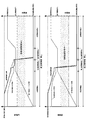
先ず、制御装置6による起動制御について説明する。図3は、起動制御の処理の流れを説明する図であり、図4は、起動制御のタイミングチャートである。図3では、低圧膨張機38の起動制御の処理の流れを説明しているが、低圧膨張機38の起動制御と高圧膨張機37の起動制御は、使用されるスケジュールや設定値等が異なるものの処理の内容は実質的に同じであり、高圧膨張機37の起動制御の処理も図3に当てはめて説明する。また、図4では、上段のチャートが、高圧膨張機回転数N1、高圧膨張機入口弁21の開度、及び高圧膨張機バイパス弁24の開度の経時変化を表し、下段のチャートが、低圧膨張機回転数N2、低圧膨張機入口弁22の開度、及び低圧膨張機バイパス弁27の開度の経時変化を表している。上段のチャートと下段のチャートの時間軸は対応している。
[Startup control]
First, start control by the
図3及び図4に示すように、起動制御は、初期冷却ステップ、初期起動ステップ、危険速度領域通過ステップ、及び、回転数昇速ステップの大きく分けて4つのステップから成る。初期冷却ステップは、膨張機37,38の起動前(即ち、回転を始める前)に行われる。
As shown in FIGS. 3 and 4, the start-up control is roughly divided into four steps: an initial cooling step, an initial start-up step, a critical speed region passing step, and a rotation speed increase step. The initial cooling step is performed before starting the
(初期冷却ステップ)
高圧膨張機37及び低圧膨張機38及びそれら周辺が液体窒素温度まで冷却されていない状態でそれらのロータ軸が回転し、その回転数が危険速度領域に突入すると、固有振動数の同期成分に起因する軸振動に加えて、固有振動数とは関係の無い非同期成分に起因する不安定振動も発生し、軸振動が過大となった場合には、軸受が焼き付くおそれがある。そこで、初期冷却ステップでは、起動前に原料ガス液化装置100の装置全体が常温状態にある場合には、初期冷却器73(窒素ライン70)を利用して、装置全体が液体窒素の温度程度となるまで初期冷却される。
(Initial cooling step)
When the rotor shafts of the high-
初期冷却ステップでは、低圧膨張機バイパス弁27の開度は、所定の循環開度から所定の初期起動開度まで下げられる。低圧膨張機バイパス弁27の開度は、回転数昇速ステップが開始されるまで、初期起動開度で維持される。
In the initial cooling step, the opening degree of the low pressure
また、初期冷却ステップでは、高圧膨張機入口弁21の開度が所定の初期冷却開度まで上げられ、初期冷却開度で維持される。高圧膨張機入口弁21の初期冷却開度は、閉止ではなく、僅かに開かれている。よって、高圧膨張機入口弁21の初期冷却開度のときに、高圧膨張機37が回転しない程度の流量の冷媒が高圧膨張機37へ流入することが許容される。
Further, in the initial cooling step, the opening degree of the high-pressure
また、初期冷却ステップでは、膨張機37,38の起動前(即ち、回転を始める前)において、低圧膨張機入口弁22の開度が閉止状態から所定の初期冷却開度まで上げられる。低圧膨張機入口弁22が初期冷却開度のときに、低圧膨張機38が回転しない程度の流量の冷媒が低圧膨張機38へ流入することが許容される。
Further, in the initial cooling step, the opening degree of the low pressure
制御装置6は、低圧膨張機入口弁22の開度が初期冷却開度になるのを待って、低圧膨張機38の初期冷却流量制御を開始する。低圧膨張機38の初期冷却流量制御では、制御装置6は、低圧膨張機入口弁22の開度を操作して、低圧膨張機入口側流量F2が所定の初期冷却流量設定値となるようにフィードバック制御する。初期冷却流量設定値は、低圧膨張機38のロータ軸を回転させない冷媒流量であって、ロータ軸が回転し始める冷媒流量の80〜90%以下の値で設定すればよい。
The
低圧膨張機38の初期冷却流量制御は、低圧膨張機出口温度T2が所定の冷却判定温度となるまで継続される。低圧膨張機出口温度T2が所定の冷却判定温度となると、低圧膨張機38の初期起動フラグがONとなる。
The initial cooling flow rate control of the low-
(低圧膨張機38の初期起動ステップ)
制御装置6は、低圧膨張機38の初期起動フラグがONとなれば、低圧膨張機38の初期起動ステップを開始する。低圧膨張機38の初期起動ステップでは、低圧膨張機入口弁22の開度のスケジュール制御と回転数制御とが選択的に行われる。
(Initial start step of low pressure expander 38)
When the initial start flag of the low-
制御装置6は、初期起動フラグがONをトリガとしてカウントアップを開始し、所定の弁開度スケジュールに基づいて、第1の開度指令を生成する。なお、低圧膨張機入口弁22の弁開度スケジュールは、カウントアップを開始してからの時間と低圧膨張機入口弁22の弁開度設定値との関係を定めている。制御装置6は、カウントアップを開始してからの時間に対応する弁開度設定値を導き出し、それに基づいて第1の開度指令を生成する。
The
また、制御装置6は、初期起動フラグがONとなると、回転数制御による第2の開度指令を生成する。具体的には、制御装置6は、低圧膨張機回転数N2を制御量とし、所定の最大回転数設定値を目標値とし、低圧膨張機入口弁22の開度を操作量とし、制御量を目標値に一致させるフィードバック制御により、第2の開度指令を生成する。ここで、低圧膨張機38の最大回転数設定値は、低圧膨張機38の危険速度領域よりも小さい回転数である。なお、危険速度領域とは、膨張機37,38に固有の回転速度領域であって、タービンが共振を起こすロータ軸の回転速度及びその周辺を含む回転速度領域のことである。
Further, when the initial start flag is turned ON, the
制御装置6は、第1の開度指令と第2の開度指令とを比較し、それらのうち小さい方の値を開度指令として低圧膨張機入口弁22へ出力する。通常、初期起動ステップの開始時に低圧膨張機38は回転していないので、弁開度スケジュール制御による第1の開度指令に基づいて低圧膨張機入口弁22が操作され、低圧膨張機入口弁22の開度の拡大に伴い低圧膨張機38が回転を始めると、回転数制御による第2の開度指令に基づいて低圧膨張機入口弁22が操作される。このように、弁開度スケジュール制御から回転数制御へ自動的に切り替わる。これにより、危険速度領域に進入することなく初期起動を行うことが可能となる。
The
(低圧膨張機38の危険速度領域通過ステップ)
低圧膨張機回転数N2が最大回転数設定値で安定したところで、危険速度領域通過フラグがONとなる。なお、膨張機37,38の「回転数が安定する」ことは、回転数の変動が所定値以下である状態が所定時間に亘って継続することを意味する。
(Step of passing through the critical speed region of the low-pressure inflator 38)
When the low-pressure expander rotation speed N2 stabilizes at the maximum rotation speed set value, the critical speed region passage flag is turned ON. The "stable rotation speed" of the
制御装置6は、危険速度領域通過フラグがONとなると、目標値を最大回転数設定値から所定の昇速前回転数設定値に切り替えて、回転数制御を行う。ここで、昇速前回転数設定値は危険速度領域を超える回転数である。
When the critical speed region passage flag is turned ON, the
制御装置6は、低圧膨張機回転数N2を制御量とし、昇速前回転数設定値を目標値とし、低圧膨張機入口弁22の開度を操作量とし、制御量を目標値に一致させるようなフィードバック制御により開度指令を生成し、それを低圧膨張機入口弁22へ出力する。これにより、低圧膨張機回転数N2は急峻に昇速前回転数設定値まで昇速して、危険速度領域を速やかに通過する。
In the
低圧膨張機回転数N2が昇速前回転数設定値で安定し、且つ、低圧膨張機入口弁22の開度が安定したところで、高圧膨張機37の初期起動フラグがONとなる。なお、後述する高圧膨張機37の初期起動ステップ及び危険速度領域通過ステップの間、制御装置6は、低圧膨張機回転数N2が昇速前回転数設定値を維持するように、低圧膨張機入口弁22の開度を制御する。
When the low-pressure inflator rotation speed N2 is stable at the set value before acceleration and the opening degree of the low-pressure
(高圧膨張機37の初期冷却/起動ステップ)
制御装置6は、高圧膨張機37の初期起動フラグがONとなると、高圧膨張機37の初期冷却/起動ステップを開始する。高圧膨張機37の起動制御は、低圧膨張機38の起動制御と同様に、初期冷却ステップ、初期起動ステップ、危険速度領域通過ステップ、及び、回転数昇速ステップから成る。
(Initial cooling / starting step of high-pressure inflator 37)
When the initial start flag of the high-
前述の通り、初期冷却ステップにおいて、高圧膨張機37には、ロータ軸が回転しない程度の流量の冷媒が既に流れている。この冷媒により、低圧膨張機38の初期起動ステップ及び危険速度領域通過ステップが行われている間に、高圧膨張機37及びその周辺が冷却される。
As described above, in the initial cooling step, the high-
高圧膨張機37の初期起動ステップでは、前述の低圧膨張機38の初期起動ステップと同様に、弁開度スケジュール制御と回転数制御とが選択的に行われる。
In the initial start-up step of the high-
具体的には、制御装置6は、初期起動フラグのONをトリガとしてカウントアップを開始し、所定の弁開度スケジュールに基づいて、第1の開度指令を生成する。一方で、制御装置6は、回転数制御により第2の開度指令を生成する。即ち、高圧膨張機回転数N1を制御量とし、所定の最大回転数設定値を目標値とし、高圧膨張機入口弁21の開度を操作量とし、制御量を目標値に一致させるようなフィードバック制御により、第2の開度指令を生成する。制御装置6は、第1の開度指令と第2の開度指令とを比較し、それらのうち小さい方の値を開度指令として高圧膨張機入口弁21へ出力する。これにより、危険速度領域に進入することなく初期起動を行うことが可能となる。
Specifically, the
(高圧膨張機37の危険速度領域通過ステップ)
高圧膨張機回転数N1が最大回転数で安定したところで、危険速度領域通過フラグがONとなる。制御装置6は、危険速度領域通過フラグがONとなると、危険速度領域通過ステップを開始する。この高圧膨張機37の危険速度領域通過ステップでは、前述の低圧膨張機38の危険速度領域通過ステップと同様に、回転数制御における目標値を最大回転数設定値から所定の昇速前回転数設定値に切り替える。
(Step of passing through the critical speed region of the high-pressure inflator 37)
When the high-pressure expander rotation speed N1 stabilizes at the maximum rotation speed, the critical speed region passage flag is turned ON. When the critical speed region passage flag is turned ON, the
制御装置6は、高圧膨張機入口弁21の開度を操作して、高圧膨張機回転数N1が昇速前回転数設定値となるようにフィードバック制御する。これにより、高圧膨張機回転数N1は急峻に昇速前回転数設定値まで昇速して、危険速度領域を速やかに通過することができる。
The
(回転数昇速ステップ)
高圧膨張機回転数N1が昇速前回転数設定値となると、回転数昇速フラグがONとなる。制御装置6は、回転数昇速フラグがONとなると、高圧膨張機37及び低圧膨張機38の回転数昇速ステップを開始する。
(Rotation speed increase step)
When the high-pressure expander rotation speed N1 becomes the rotation speed setting value before acceleration, the rotation speed increase flag is turned ON. When the rotation speed increase flag is turned ON, the
回転数昇速ステップにおいて、制御装置6は、高圧膨張機バイパス弁24の開度を、初期起動開度から所定の定常運転開度まで所定の減少率で下げる。同様に、制御装置6は、低圧膨張機バイパス弁27の開度を、初期起動開度から所定の定常運転開度まで所定の減少率で下げる。
In the rotation speed increase step, the
また、回転数昇速ステップにおいて、制御装置6は、回転数昇速フラグがONとなるとカウントアップを開始し、所定の回転数昇速スケジュールに基づいて回転数の目標値を求め、高圧膨張機入口弁21の開度を操作して、高圧膨張機回転数N1を目標値と一致させるようにフィードバック制御する。その結果、高圧膨張機回転数N1は、昇速前回転数設定値からを高圧膨張機37の定格回転数まで上昇する。
Further, in the rotation speed acceleration step, the
同様に、制御装置6は、所定の回転数昇速スケジュールに基づいて回転数の目標値を求め、低圧膨張機入口弁22の開度を操作して、低圧膨張機回転数N2を目標値と一致させるようにフィードバック制御する。その結果、低圧膨張機回転数N2は、昇速前回転数設定値からを低圧膨張機38の定格回転数まで上昇する。
Similarly, the
このように、高圧膨張機バイパス弁24及び低圧膨張機バイパス弁27の開度を回転数に関係なく所定の減少率で下げることで、回転数制御により自動調整される高圧膨張機入口弁21及び低圧膨張機入口弁22の開度変化との干渉を避けることができ、膨張機37,38の過回転及び急昇速を防止することができる。
In this way, by reducing the opening degree of the high-pressure
冷媒温度の急速な低下又は上昇により、熱交換器81〜86が急速に冷却又は加温されると、ヒートショックにより熱交換器内の例えばプレートフィンが損傷するおそれがある。このような熱交換器81〜86にかかる負荷を軽減するために、膨張機37,38の起動及び停止の際には、熱交換器81〜86における温度変化を所定の許容範囲に収めなければならない。そこで、高圧膨張機37の回転数昇速スケジュールは、熱交換器81〜86の温度変化を所定の許容範囲内に抑えながら、高圧膨張機37の回転数を昇速前回転数設定値からを定格回転数まで上昇させるような、時間と高圧膨張機37の回転数(目標値)との関係を定めている。同様に、低圧膨張機38の回転数昇速スケジュールは、熱交換器81〜86の温度変化を所定の許容範囲内に抑えながら、低圧膨張機38の回転数を昇速前回転数設定値からを定格回転数まで上昇させるような、時間と低圧膨張機38の回転数(目標値)との関係を定めている。
If the heat exchangers 81-86 are rapidly cooled or heated due to a rapid decrease or rise in the refrigerant temperature, heat shock may damage, for example, plate fins in the heat exchanger. In order to reduce the load on the
そして、制御装置6は、高圧膨張機回転数N1が定格回転数で安定し、且つ、高圧膨張機バイパス弁24の開度が定常運転開度となったところで、高圧膨張機37の回転数昇速ステップを終了する。同様に、制御装置6は、低圧膨張機回転数N2が定格回転数で安定し、且つ、低圧膨張機バイパス弁27の開度が定常運転開度となったところで、低圧膨張機38の回転数昇速ステップを終了する。高圧膨張機37及び低圧膨張機38の回転数昇速ステップの終了タイミングは、各々の回転数昇速スケジュールによって概ね同時となるように予定されている。制御装置6は、高圧膨張機37及び低圧膨張機38の回転数昇速ステップが終了すると、高圧膨張機37及び低圧膨張機38の起動制御を終了する。
Then, in the
〔停止制御〕
次に、制御装置6による停止制御について説明する。図5は、停止制御の処理の流れを説明する図、図6は、停止制御のタイミングチャートである。図5では、低圧膨張機38の停止制御の処理の流れを説明しているが、低圧膨張機38の停止制御と高圧膨張機37の停止制御は、使用されるスケジュールや設定値等が異なるものの処理の内容は実質的に同じであり、高圧膨張機37の停止制御の処理も図5に当てはめて説明する。図6では、上段のチャートが、高圧膨張機回転数N1、高圧膨張機入口弁21の開度、及び高圧膨張機バイパス弁24の開度の経時変化を表し、下段のチャートが、低圧膨張機回転数N2、低圧膨張機入口弁22の開度、及び低圧膨張機バイパス弁27の開度の経時変化を表している。上段のチャートと下段のチャートの時間軸は対応している。
[Stop control]
Next, stop control by the
図5及び図6に示すように、制御装置6は、停止制御を開始すると、高圧膨張機バイパス弁24の開度を、循環開度から停止開度へ所定の増加率で上げるとともに、低圧膨張機バイパス弁27の開度を、定常運転開度から停止開度へ所定の増加率で上げる。
As shown in FIGS. 5 and 6, when the stop control is started, the
制御装置6は、停止制御を開始すると回転数減速フラグがONとなって、カウントアップを開始し、所定の高圧膨張機37の回転数減速スケジュールに基づいて回転数の目標値を求める。そして、制御装置6は、高圧膨張機入口弁21の開度を操作して、高圧膨張機回転数N1を目標値と一致させるようにフィードバック制御する。その結果、高圧膨張機回転数N1は、高圧膨張機37の定格回転数から所定の停止前回転数まで減速する。なお、高圧膨張機37の回転数減速スケジュールは、熱交換器81〜86の温度変化を所定の許容範囲内に抑えながら、高圧膨張機37の回転数を定格回転数から停止前回転数まで減速させるような、時間と高圧膨張機37の回転数(目標値)との関係を定めている。
When the
同様に、制御装置6は、所定の低圧膨張機38の回転数減速スケジュールに基づいて回転数の目標値を求める。そして、制御装置6は、低圧膨張機入口弁22の開度を操作して、低圧膨張機回転数N2を目標値と一致させるようにフィードバック制御する。その結果、低圧膨張機回転数N2は、低圧膨張機38の定格回転数から所定の停止前回転数まで減速する。なお、低圧膨張機38の回転数減速スケジュールは、熱交換器81〜86の温度変化を所定の許容範囲内に抑えながら、低圧膨張機38の回転数を定格回転数から停止前回転数まで減速させるような、時間と低圧膨張機38の回転数(目標値)の関係を定めている。
Similarly, the
このように、高圧膨張機バイパス弁24及び低圧膨張機バイパス弁27の開度を回転数に関係なく所定の増加率で下げることで、回転数制御により自動調整される高圧膨張機入口弁21及び低圧膨張機入口弁22の開度変化との干渉を避けることができ、膨張機37,38の過回転及び急減速を防止することができる。
In this way, by reducing the opening degree of the high-pressure
高圧膨張機回転数N1が停止前回転数で安定し、且つ、高圧膨張機バイパス弁24が停止開度となれば高圧膨張機37の減速は停止する。低圧膨張機回転数N2が停止前回転数で安定し、且つ、低圧膨張機バイパス弁27が停止開度となれば低圧膨張機38の減速は停止する。そして、膨張機37,38が共に停止状態となった時点で回転数減速フラグがOFFとなる。
When the high-pressure inflator rotation speed N1 stabilizes at the rotation speed before the stop and the high-pressure
制御装置6は、回転数減速フラグがOFFとなると、高圧膨張機入口弁21及び低圧膨張機入口弁22に閉止の開度指令を出力する。これにより、高圧膨張機入口弁21が閉止され、高圧膨張機回転数N1は急峻に0まで減速し、危険速度領域を速やかに通過することができる。同様に、低圧膨張機入口弁22が閉止され、低圧膨張機回転数N2は急峻に0まで減速し、危険速度領域を速やかに通過することができる。このように、膨張機37,38が危険速度領域を速やかに通過するので、軸振動過大を回避しつつ、膨張機37,38を停止させることができる。なお、上記停止制御の完了後、高圧膨張機バイパス弁24及び低圧膨張機バイパス弁27の開度を、停止開度から循環開度へ所定の増加率で上げる。
When the rotation speed deceleration flag is turned off, the
以上に説明した通り、本実施形態に係る原料ガス液化装置100は、沸点が窒素ガスよりも低温である原料ガスを供給するフィードライン1と、原料ガスを冷却するための冷媒が循環する冷媒循環ライン3であって、冷媒を膨張させて冷熱を生成するタービン式の膨張機37,38、及び、膨張機37,38の入口側に設けられた膨張機入口弁21,22を有する冷媒循環ライン3と、原料ガスと冷媒との熱交換が行われる熱交換器81〜86と、液体窒素との熱交換により原料ガス及び冷媒の初期冷却を行う冷却器73と、膨張機37,38の回転数N1,N2を検出する膨張機回転数センサ56,57と、フィードライン1及び冷媒循環ライン3に関する動作制御を行う制御装置6とを備えている。
As described above, in the raw
そして、制御装置6が、膨張機37,38の起動時及び停止時において、膨張機37,38の回転数N1,N2を所定の目標値と一致させるフィードバック制御により膨張機入口弁21,22の開度指令を生成し、当該開度指令を膨張機入口弁21,22に出力することを特徴としている。
Then, when the
また、本実施形態に係る原料ガス液化装置100の制御方法は、膨張機37,38の起動時及び停止時において、膨張機入口弁21,22の開度を操作して、膨張機37,38の回転数N1,N2を所定の目標値と一致させるようにフィードバック制御することを特徴としている。
Further, in the control method of the raw
上記原料ガス液化装置100及びその制御方法では、膨張機37,38の起動時及び停止時に、膨張機入口弁21,22の弁開度ではなく、膨張機37,38の回転数が直接的に制御される。これにより、膨張機37,38の起動時及び停止時においても、膨張機37,38で生成される冷熱を制御することが可能となる。また、膨張機37,38の運転特性が変化しても、膨張機37,38の起動時及び停止時に、膨張機37,38の回転数が予定なく危険速度領域に突入することを回避できる。また、膨張機37,38の回転数を制御することにより、危険速度領域を速やかに通過させて、膨張機37,38の軸振動を抑えることができる。その結果、膨張機37,38の軸受の焼き付き等、膨張機37,38の軸振動の過大に起因する損傷を回避することができる。
In the raw
また、本実施形態に係る原料ガス液化装置100及びその制御方法では、制御装置6が、膨張機37の起動の前に、膨張機37を回転させない所定の初期冷却流量の初期冷却された冷媒が膨張機37に導入されるように、膨張機入口弁21の開度指令を生成し、当該開度指令を膨張機入口弁21に出力する。
Further, in the raw material
このように、膨張機37,38の起動の前に、膨張機38を回転させない初期冷却流量の冷媒が膨張機38に導入されるように、膨張機入口弁22の開度を操作して冷却流量が制御されることによって、膨張機38を回転させないで膨張機38及びその周辺を冷却することができる。特許文献1のように、膨張機38の軸受の軸シール漏れを利用して膨張機38及びその周辺の冷却を行う場合と比較して、冷媒の流量の制限が緩やかとなり、冷却を開始してから膨張機37,38の起動が完了するまでに要する時間を短縮することができる。
In this way, before starting the
なお、上記実施形態においては、低圧膨張機38に対し初期冷却流量制御を行っているが、高圧膨張機37に対し同様の初期冷却流量制御が行われてもよい。
In the above embodiment, the initial cooling flow rate control is performed on the
また、本実施形態に係る原料ガス液化装置100及びその制御方法において、制御装置6は、膨張機37,38の起動時において、膨張機37,38の回転数を当該膨張機37の危険速度領域よりも小さい所定の最大回転数設定値まで上昇させる所定の弁開度スケジュールに基づいて、膨張機入口弁21,22の第1の開度指令を求め、目標値を最大回転数設定値とし、膨張機37の回転数を最大回転数設定値に一致させるフィードバック制御により膨張機入口弁21,22の第2の開度指令を求め、第1の開度指令及び第2の開度指令のうち値の小さい方の開度指令を膨張機入口弁21,22に出力する。
Further, in the raw material
上記のような、弁開度スケジュール制御によれば、膨張機37,38の機器の経年劣化や冷媒に含まれる不純物のタービン軸受への固着等によって、膨張機37,38の運転特性(回転始動・停止特性)が変化した場合であっても、膨張機37,38の初期起動を開始することができる。また、最大回転数を目標値とする回転数制御によれば、膨張機37,38が回転を開始した直後に過回転傾向となった場合でも、膨張機37,38の回転数が一気に危険速度領域へ突入することを回避できる。
According to the valve opening schedule control as described above, the operating characteristics (rotational start) of the
また、本実施形態に係る原料ガス液化装置100及びその制御方法では、膨張機37,38の起動時であって、膨張機37,38の危険速度領域を超える所定の昇速前回転数から膨張機37,38の定格回転数まで膨張機の回転数を上昇させるときに、制御装置6が、膨張機37,38の回転数の変化に伴う熱交換器81〜86の温度変化を所定の許容範囲内に抑えながら膨張機37,38の回転数を上昇させる所定の回転数昇速スケジュールに基づいて、回転数制御の目標値を決定する。
Further, in the raw material
同様に、本実施形態に係る原料ガス液化装置100及びその制御方法では、膨張機37,38の停止時であって、膨張機37,38の定格回転数から膨張機37,38の危険速度領域を超える所定の停止前回転数まで膨張機37,38の回転数を降下させるときに、制御装置6が、膨張機37,38の回転数の変化に伴う熱交換器81〜86の温度変化を所定の許容範囲内に抑えながら膨張機37,38の回転数を降下させる所定の回転数減速スケジュールに基づいて、回転数制御の目標値を決定する。
Similarly, in the raw
このように、高圧膨張機37及び低圧膨張機38の回転数が、回転数昇速スケジュールに従って徐々に上昇(昇速)し、又は、回転数減速スケジュールに従って徐々に降下(減速)することで、高圧膨張機37及び低圧膨張機38の生成冷熱量不足による熱交換器81〜86の温度上昇を許容範囲内に抑えることができる。これにより、熱交換器81〜86において、ヒートショックに起因するプレートフィンの損傷を防止することができる。
In this way, the rotation speeds of the high-
また、本実施形態に係る原料ガス液化装置100及びその制御方法では、膨張機37,38には、高圧膨張機37と、当該高圧膨張機37の下流側に設けられた低圧膨張機38とが含まれ、膨張機入口弁21,22には、高圧膨張機37の入口側に設けられた高圧膨張機入口弁21と、低圧膨張機38の入口側に設けられた低圧膨張機入口弁22とが含まれている。そして、制御装置6は、低圧膨張機38の回転数が当該低圧膨張機38の危険速度領域を超える所定の昇速前回転数に到達してから、高圧膨張機37の回転数が当該高圧膨張機37の危険速度領域を超える所定の昇速前回転数に到達し、高圧膨張機37及び低圧膨張機38が共に各自の昇速前回転数に到達してから、高圧膨張機37及び低圧膨張機38の回転数を各自の昇速前回転数から各自の定格回転数まで上昇させるように、低圧膨張機38及び高圧膨張機37の回転数を制御する。
Further, in the raw
このように、高圧膨張機37及び低圧膨張機38が共に、危険速度領域を上回る各自の昇速前回転数に到達してから、高圧膨張機37及び低圧膨張機38の回転数を各自の定格回転数まで回転させることによって、高圧膨張機37及び低圧膨張機38の回転数が予期せず危険速度領域に突入することを確実に回避することができる。また、高圧膨張機37と低圧膨張機38とで、危険速度領域を通過させるタイミング(即ち、回転数が急峻に変化するタイミング)がシフトするので、軸振動を抑え、より安定した起動制御を行うことができる。
In this way, after both the high-
以上に本発明の好適な実施の形態を説明したが、本発明の精神を逸脱しない範囲で、上記実施形態の具体的な構造及び/又は機能の詳細を変更したものも本発明に含まれ得る。上記の原料ガス液化装置100の構成は、例えば、以下のように変更することができる。
Although the preferred embodiment of the present invention has been described above, the present invention may include modified details of the specific structure and / or function of the above embodiment without departing from the spirit of the present invention. .. The configuration of the raw
上記実施形態に係る原料ガス液化装置100では、2台の膨張機37,38を備えている。しかしながら、これらの台数は、膨張機37,38の性能に依存するものであり、上記実施形態に限定されるものではない。
The raw
例えば、膨張機は1台であってもよい。この場合、高圧膨張機37の起動制御及び停止制御が省略されることを除いて、上記実施形態と実質的に同じように原料ガス液化装置100の動作が制御される。また、例えば、膨張機は3台以上であってもよい。この場合、増えた分の膨張機に関して高圧膨張機37の起動制御及び停止制御と同様の制御が追加されることを除いて、上記実施形態と実質的に同じように原料ガス液化装置100の動作が制御される。
For example, the number of expanders may be one. In this case, the operation of the raw material
また、上記実施形態に係る原料ガス液化装置100では、低圧膨張機38の初期起動ステップと危険速度領域通過ステップとを行ってから、高圧膨張機37の初期起動ステップと危険速度領域通過ステップを行っているが、先後の順を変えて、後者が先で前者が後に行われてもよい。この場合、制御装置6は、高圧膨張機37の初期起動ステップの前に、高圧膨張機37を回転させない所定の初期冷却流量の初期冷却された冷媒が高圧膨張機37に導入されるように、高圧膨張機入口弁21の開度指令を生成し、当該開度指令を高圧膨張機入口弁21に出力する。
Further, in the raw
また、上記実施形態に係る原料ガス液化装置100では、2台の圧縮機32,33を備えており、6段の熱交換器81〜86を備えている。しかしながら、これらの台数は、圧縮機32,33及び熱交換器81〜86の性能に依存するものであり、上記実施形態に限定されるものではない。
Further, the raw
1 :フィードライン
3 :冷媒循環ライン
6 :制御装置
16 :供給系ジュールトムソン弁
20 :液化機
21 :高圧膨張機入口弁
22 :低圧膨張機入口弁
23 :高圧膨張機バイパス流路
24 :高圧膨張機バイパス弁
26 :低圧膨張機バイパス流路
27 :低圧膨張機バイパス弁
31C :冷熱生成流路
32 :低圧圧縮機
33 :高圧圧縮機
36 :循環系ジュールトムソン弁
37 :高圧膨張機
38 :低圧膨張機
40 :液化冷媒貯槽
41 :冷媒液化ルート
42 :冷熱生成ルート
51 :高圧膨張機出口温度センサ
52 :低圧膨張機出口温度センサ
56 :高圧膨張機回転数センサ
57 :低圧膨張機回転数センサ
58 :高圧膨張機入口側流量センサ
59 :低圧膨張機入口側流量センサ
61 :起動制御部
62 :停止制御部
70 :窒素ライン
71 :液体窒素貯槽
73 :初期冷却器
81〜86 :熱交換器
88 :冷却器
100 :原料ガス液化装置
1: Feed line 3: Coolant circulation line 6: Control device 16: Supply system Jules Thomson valve 20: Liquefaction machine 21: High-pressure inflator inlet valve 22: Low-pressure inflator inlet valve 23: High-pressure inflator bypass flow path 24: High-pressure expansion Machine bypass valve 26: Low-pressure inflator bypass flow path 27: Low-pressure
Claims (12)
前記原料ガスを冷却するための冷媒が循環する冷媒循環ラインであって、前記冷媒を膨張させて冷熱を生成するタービン式の膨張機、及び、前記膨張機の入口側に設けられた膨張機入口弁を有する冷媒循環ラインと、
前記原料ガスと前記冷媒との熱交換が行われる熱交換器と、
液体窒素との熱交換により前記原料ガス及び前記冷媒の初期冷却を行う冷却器と、
前記膨張機の回転数を検出する膨張機回転数センサと、
前記膨張機の起動時及び停止時において、前記膨張機の回転数を所定の目標値と一致させるフィードバック制御により前記膨張機入口弁の開度指令を生成し、当該開度指令を前記膨張機入口弁に出力する制御装置と、を備え、
前記制御装置が、前記膨張機の起動時において、
前記膨張機の回転数を当該膨張機の危険速度領域よりも小さい所定の最大回転数設定値まで上昇させる所定の弁開度スケジュールに基づいて、前記膨張機入口弁の第1の開度指令を求め、
前記目標値を前記最大回転数設定値とし、前記膨張機の回転数を前記最大回転数設定値に一致させるフィードバック制御により前記膨張機入口弁の第2の開度指令を求め、
前記第1の開度指令及び前記第2の開度指令のうち値の小さい方の開度指令を前記膨張機入口弁に出力する、
原料ガス液化装置。 A feed line that supplies a raw material gas whose boiling point is lower than that of nitrogen gas,
A refrigerant circulation line in which a refrigerant for cooling the raw material gas circulates, a turbine-type expander that expands the refrigerant to generate cold heat, and an expander inlet provided on the inlet side of the expander. Refrigerant circulation line with valve and
A heat exchanger that exchanges heat between the raw material gas and the refrigerant,
A cooler that initially cools the raw material gas and the refrigerant by heat exchange with liquid nitrogen,
An inflator rotation speed sensor that detects the rotation speed of the inflator, and
When the inflator is started and stopped, the inflator inlet valve opening command is generated by feedback control that matches the rotation speed of the inflator with a predetermined target value, and the opening command is sent to the inflator inlet. and a control unit for outputting to the valve,
When the control device starts the inflator,
The first opening command of the inflator inlet valve is issued based on a predetermined valve opening schedule that raises the rotation speed of the inflator to a predetermined maximum rotation speed set value smaller than the critical speed region of the inflator. Ask,
The target value is set as the maximum rotation speed setting value, and the second opening command of the expansion machine inlet valve is obtained by feedback control for matching the rotation speed of the expansion machine with the maximum rotation speed setting value.
You output opening command of the smaller of said first opening command and the second value out of the opening command to the expander inlet valve,
Raw material gas liquefaction device.
請求項1に記載の原料ガス液化装置。 The controller opens the expander inlet valve so that the initially cooled refrigerant at a predetermined initial cooling flow rate that does not rotate the expander is introduced into the expander prior to activation of the expander. Generates a degree command and outputs the opening command to the expander inlet valve.
The raw material gas liquefaction apparatus according to claim 1.
前記制御装置が、前記膨張機の回転数の変化に伴う前記熱交換器の温度変化を所定の許容範囲内に抑えながら前記膨張機の回転数を上昇させる所定の回転数昇速スケジュールに基づいて、前記目標値を決定する、
請求項1又は2に記載の原料ガス液化装置。 When the inflator is started and the rotation speed of the inflator is increased from a predetermined pre-acceleration rotation speed exceeding the critical speed region of the inflator to the rated rotation speed of the inflator.
Based on a predetermined rotation speed acceleration schedule in which the control device increases the rotation speed of the inflator while suppressing the temperature change of the heat exchanger accompanying the change in the rotation speed of the inflator within a predetermined allowable range. , Determine the target value,
The raw material gas liquefaction apparatus according to claim 1 or 2.
前記制御装置が、前記膨張機の回転数の変化に伴う前記熱交換器の温度変化を所定の許容範囲内に抑えながら前記膨張機の回転数を降下させる所定の回転数減速スケジュールに基づいて、前記目標値を決定する、
請求項1〜3のいずれか一項に記載の原料ガス液化装置。 When the inflator is stopped and the rotation speed of the inflator is lowered from the rated rotation speed of the inflator to a predetermined pre-stop rotation speed exceeding the critical speed range of the inflator.
Based on a predetermined rotation speed deceleration schedule in which the control device lowers the rotation speed of the inflator while suppressing the temperature change of the heat exchanger accompanying the change in the rotation speed of the inflator within a predetermined allowable range. To determine the target value,
The raw material gas liquefaction apparatus according to any one of claims 1 to 3.
前記膨張機入口弁は、前記高圧膨張機の入口側に設けられた高圧膨張機入口弁と、前記低圧膨張機の入口側に設けられた低圧膨張機入口弁とを含み、
前記制御装置は、前記低圧膨張機の回転数が当該低圧膨張機の危険速度領域を超える所定の昇速前回転数に到達してから、前記高圧膨張機の回転数が当該高圧膨張機の危険速度領域を超える所定の昇速前回転数に到達し、前記高圧膨張機及び前記低圧膨張機が共に各
自の前記昇速前回転数に到達してから、前記高圧膨張機及び前記低圧膨張機の回転数を各自の前記昇速前回転数から各自の定格回転数まで上昇させるように、前記低圧膨張機及び前記高圧膨張機の回転数を制御する、
請求項1〜4のいずれか一項に記載の原料ガス液化装置。 The inflator includes a high-pressure inflator and a low-pressure inflator provided on the downstream side of the high-pressure inflator.
The inflator inlet valve includes a high-pressure inflator inlet valve provided on the inlet side of the high-pressure inflator and a low-pressure inflator inlet valve provided on the inlet side of the low-pressure inflator.
In the control device, after the rotation speed of the low-pressure inflator reaches a predetermined pre-acceleration rotation speed exceeding the dangerous speed range of the low-pressure inflator, the rotation speed of the high-pressure inflator becomes dangerous for the high-pressure inflator. After reaching a predetermined pre-acceleration rotation speed exceeding the speed range and both the high-pressure inflator and the low-pressure inflator reaching the pre-acceleration rotation speed of their own, the high-pressure inflator and the low-pressure inflator The rotation speeds of the low-pressure inflator and the high-pressure inflator are controlled so as to increase the rotation speed from the rotation speed before acceleration to the rated rotation speed of each person.
The raw material gas liquefaction apparatus according to any one of claims 1 to 4.
前記原料ガスを冷却するための冷媒が循環する冷媒循環ラインであって、前記冷媒を膨張させて冷熱を生成するタービン式の膨張機、及び、前記膨張機の入口側に設けられた膨張機入口弁を有する冷媒循環ラインと、
前記原料ガスと前記冷媒との熱交換が行われる熱交換器と、
液体窒素との熱交換により前記原料ガス及び前記冷媒の初期冷却を行う冷却器と、
前記フィードライン及び前記冷媒循環ラインに関する動作制御を行う制御装置とを備えた原料ガス液化装置の制御方法であって、
前記膨張機の起動時及び停止時において、前記膨張機入口弁の開度を操作して、前記膨張機の回転数を所定の目標値と一致させるようにフィードバック制御し、
前記膨張機の起動時において、前記膨張機の回転数を当該膨張機の危険速度領域よりも小さい所定の最大回転数設定値まで上昇させる所定の弁開度スケジュールに基づく前記膨張機入口弁の第1の開度指令と、前記目標値を前記最大回転数設定値とし、前記膨張機の回転数を前記目標値に一致させるフィードバック制御に基づく前記膨張機入口弁の第2の開度指令とのうち、値の小さい方の開度指令に基づいて前記膨張機入口弁の開度を操作する、
原料ガス液化装置の制御方法。 A feed line that supplies a raw material gas whose boiling point is lower than that of nitrogen gas,
A refrigerant circulation line in which a refrigerant for cooling the raw material gas circulates, a turbine-type expander that expands the refrigerant to generate cold heat, and an expander inlet provided on the inlet side of the expander. Refrigerant circulation line with valve and
A heat exchanger that exchanges heat between the raw material gas and the refrigerant,
A cooler that initially cools the raw material gas and the refrigerant by heat exchange with liquid nitrogen,
A control method for a raw material gas liquefier including a control device for controlling the operation of the feed line and the refrigerant circulation line.
When the inflator is started and stopped, the opening degree of the inflator inlet valve is operated to feedback control the rotation speed of the inflator so as to match a predetermined target value .
When the inflator is started, the number of the inflator inlet valve based on a predetermined valve opening schedule that raises the rotation speed of the inflator to a predetermined maximum rotation speed set value smaller than the dangerous speed region of the inflator. The opening command of 1 and the second opening command of the expander inlet valve based on the feedback control in which the target value is set to the maximum rotation speed setting value and the rotation speed of the expander matches the target value. Of these, the opening degree of the expander inlet valve is operated based on the opening degree command of the smaller value .
Control method of raw material gas liquefier.
請求項6に記載の原料ガス液化装置の制御方法。 Prior to the activation of the inflator, the opening degree of the inflator inlet valve is manipulated so that the initially cooled refrigerant at a predetermined initial cooling flow rate that does not rotate the inflator is introduced into the inflator. , Control the flow rate introduced into the expander to the initial cooling flow rate.
The control method for a raw material gas liquefier according to claim 6.
請求項6又は7に記載の原料ガス液化装置の制御方法。 When the inflator is started and the rotation speed of the inflator is increased from a predetermined pre-acceleration rotation speed exceeding the critical speed range of the inflator to the rated rotation speed of the inflator, the inflator The target value is obtained based on a predetermined rotation speed acceleration schedule that increases the rotation speed of the expander while suppressing the temperature change of the heat exchanger accompanying the change in the rotation speed of the above within a predetermined allowable range.
The control method for a raw material gas liquefier according to claim 6 or 7.
請求項6〜8のいずれか一項に記載の原料ガス液化装置の制御方法。 When the inflator is stopped and the rotation speed of the inflator is lowered from the rated rotation speed of the inflator to a predetermined rotation speed before stopping that exceeds the critical speed range of the inflator, the inflator The target value is obtained based on a predetermined rotation speed deceleration schedule for lowering the rotation speed while suppressing the temperature change of the heat exchanger due to the change in the rotation speed within a predetermined allowable range.
The control method for a raw material gas liquefier according to any one of claims 6 to 8.
前記膨張機入口弁は、前記高圧膨張機の入口側に設けられた高圧膨張機入口弁と、前記低圧膨張機の入口側に設けられた低圧膨張機入口弁とを含み、
前記低圧膨張機の回転数が当該低圧膨張機の危険速度領域を超える所定の昇速前回転数に到達してから、前記高圧膨張機の回転数が当該高圧膨張機の危険速度領域を超える所定の昇速前回転数に到達し、前記高圧膨張機及び前記低圧膨張機が共に各自の前記昇速前回転数に到達してから、前記高圧膨張機及び前記低圧膨張機の回転数を各自の前記昇速前回転数から各自の定格回転数まで上昇させるように、前記低圧膨張機及び前記高圧膨張機の回転数を制御する、
請求項6〜9のいずれか一項に記載の原料ガス液化装置の制御方法。 The inflator includes a high-pressure inflator and a low-pressure inflator provided on the downstream side of the high-pressure inflator.
The inflator inlet valve includes a high-pressure inflator inlet valve provided on the inlet side of the high-pressure inflator and a low-pressure inflator inlet valve provided on the inlet side of the low-pressure inflator.
After the rotation speed of the low-pressure inflator reaches a predetermined pre-acceleration rotation speed exceeding the dangerous speed region of the low-pressure inflator, the rotation speed of the high-pressure inflator exceeds the dangerous speed region of the high-pressure inflator. After reaching the pre-acceleration rotation speed of, and after both the high-pressure inflator and the low-pressure inflator have reached their own pre-acceleration rotation speeds, the rotation speeds of the high-pressure inflator and the low-pressure inflator are set to their own. The rotation speeds of the low-pressure inflator and the high-pressure inflator are controlled so as to increase the rotation speed before acceleration to the rated rotation speed of each person.
The control method for a raw material gas liquefier according to any one of claims 6 to 9.
前記原料ガスを冷却するための冷媒が循環する冷媒循環ラインであって、前記冷媒を膨張させて冷熱を生成するタービン式の膨張機、及び、前記膨張機の入口側に設けられた膨張機入口弁を有する冷媒循環ラインと、
前記原料ガスと前記冷媒との熱交換が行われる熱交換器と、
液体窒素との熱交換により前記原料ガス及び前記冷媒の初期冷却を行う冷却器と、
前記膨張機の回転数を検出する膨張機回転数センサと、
前記膨張機の起動時及び停止時において、前記膨張機の回転数を所定の目標値と一致させるフィードバック制御により前記膨張機入口弁の開度指令を生成し、当該開度指令を前記膨張機入口弁に出力する制御装置と、を備え、
前記制御装置が、前記膨張機の起動の前に、前記膨張機入口弁が開いて前記膨張機を回転させない所定の初期冷却流量の初期冷却された前記冷媒が前記膨張機に導入されるように、前記膨張機入口弁の開度指令を生成し、当該開度指令を前記膨張機入口弁に出力する、
原料ガス液化装置。 A feed line that supplies a raw material gas whose boiling point is lower than that of nitrogen gas,
A refrigerant circulation line in which a refrigerant for cooling the raw material gas circulates, a turbine-type expander that expands the refrigerant to generate cold heat, and an expander inlet provided on the inlet side of the expander. Refrigerant circulation line with valve and
A heat exchanger that exchanges heat between the raw material gas and the refrigerant,
A cooler that initially cools the raw material gas and the refrigerant by heat exchange with liquid nitrogen,
An inflator rotation speed sensor that detects the rotation speed of the inflator, and
When the inflator is started and stopped, the inflator inlet valve opening command is generated by feedback control that matches the rotation speed of the inflator with a predetermined target value, and the opening command is sent to the inflator inlet. Equipped with a control device that outputs to the valve
Prior to the activation of the inflator, the control device is such that the initially cooled refrigerant at a predetermined initial cooling flow rate that does not open the inflator inlet valve to rotate the inflator is introduced into the inflator. , Generates the opening command of the expander inlet valve, and outputs the opening command to the expander inlet valve.
Raw material gas liquefaction device.
前記原料ガスを冷却するための冷媒が循環する冷媒循環ラインであって、前記冷媒を膨張させて冷熱を生成するタービン式の膨張機、及び、前記膨張機の入口側に設けられた膨張機入口弁を有する冷媒循環ラインと、A refrigerant circulation line in which a refrigerant for cooling the raw material gas circulates, a turbine-type expander that expands the refrigerant to generate cold heat, and an expander inlet provided on the inlet side of the expander. Refrigerant circulation line with valve and
前記原料ガスと前記冷媒との熱交換が行われる熱交換器と、A heat exchanger that exchanges heat between the raw material gas and the refrigerant,
液体窒素との熱交換により前記原料ガス及び前記冷媒の初期冷却を行う冷却器と、A cooler that initially cools the raw material gas and the refrigerant by heat exchange with liquid nitrogen,
前記フィードライン及び前記冷媒循環ラインに関する動作制御を行う制御装置とを備えた原料ガス液化装置の制御方法であって、A control method for a raw material gas liquefier including a control device for controlling the operation of the feed line and the refrigerant circulation line.
前記膨張機の起動の前に、前記膨張機入口弁が開いて前記膨張機を回転させない所定の初期冷却流量の初期冷却された前記冷媒が前記膨張機に導入されるように、前記膨張機入口弁の開度を操作して、前記膨張機に導入される流量を前記初期冷却流量に制御し、Prior to activation of the inflator, the inflator inlet is such that the initially cooled refrigerant at a predetermined initial cooling flow rate that does not open the inflator inlet valve to rotate the inflator is introduced into the inflator. By manipulating the opening degree of the valve, the flow rate introduced into the expander is controlled to the initial cooling flow rate.
前記膨張機の起動時及び停止時において、前記膨張機入口弁の開度を操作して、前記膨張機の回転数を所定の目標値と一致させるようにフィードバック制御する、When the inflator is started and stopped, the opening degree of the inflator inlet valve is manipulated to control feedback so that the rotation speed of the inflator matches a predetermined target value.
原料ガス液化装置の制御方法。Control method of raw material gas liquefier.
Priority Applications (6)
| Application Number | Priority Date | Filing Date | Title |
|---|---|---|---|
| JP2016238535A JP6845675B2 (en) | 2016-12-08 | 2016-12-08 | Raw material gas liquefier and its control method |
| AU2017373438A AU2017373438B2 (en) | 2016-12-08 | 2017-12-04 | Raw material gas liquefying device and method of controlling this raw material gas liquefying device |
| US16/465,430 US11808502B2 (en) | 2016-12-08 | 2017-12-04 | Raw material gas liquefying device and method of controlling this raw material gas liquefying device |
| EP17878280.1A EP3553436A4 (en) | 2016-12-08 | 2017-12-04 | Raw material gas liquefaction device and control method for same |
| CN201780056417.1A CN109690216B (en) | 2016-12-08 | 2017-12-04 | Raw material gas liquefaction device and control method thereof |
| PCT/JP2017/043510 WO2018105565A1 (en) | 2016-12-08 | 2017-12-04 | Raw material gas liquefaction device and control method for same |
Applications Claiming Priority (1)
| Application Number | Priority Date | Filing Date | Title |
|---|---|---|---|
| JP2016238535A JP6845675B2 (en) | 2016-12-08 | 2016-12-08 | Raw material gas liquefier and its control method |
Publications (2)
| Publication Number | Publication Date |
|---|---|
| JP2018096556A JP2018096556A (en) | 2018-06-21 |
| JP6845675B2 true JP6845675B2 (en) | 2021-03-24 |
Family
ID=62491512
Family Applications (1)
| Application Number | Title | Priority Date | Filing Date |
|---|---|---|---|
| JP2016238535A Active JP6845675B2 (en) | 2016-12-08 | 2016-12-08 | Raw material gas liquefier and its control method |
Country Status (6)
| Country | Link |
|---|---|
| US (1) | US11808502B2 (en) |
| EP (1) | EP3553436A4 (en) |
| JP (1) | JP6845675B2 (en) |
| CN (1) | CN109690216B (en) |
| AU (1) | AU2017373438B2 (en) |
| WO (1) | WO2018105565A1 (en) |
Families Citing this family (4)
| Publication number | Priority date | Publication date | Assignee | Title |
|---|---|---|---|---|
| EP3737886A4 (en) * | 2018-01-12 | 2021-10-13 | Agility Gas Technologies LLC | Thermal cascade for cryogenic storage and transport of volatile gases |
| US11391511B1 (en) * | 2021-01-10 | 2022-07-19 | JTurbo Engineering & Technology, LLC | Methods and systems for hydrogen liquefaction |
| US20220390170A1 (en) * | 2021-06-07 | 2022-12-08 | Saudi Arabian Oil Company | Optimized natural gas production control system with actual flow and set point tracking features |
| CN114923295B (en) * | 2022-06-27 | 2024-02-20 | 北京中科富海低温科技有限公司 | Variable working condition adjusting method for two-stage series-connection intermediate heat exchange turbine expander |
Family Cites Families (13)
| Publication number | Priority date | Publication date | Assignee | Title |
|---|---|---|---|---|
| US3939328A (en) * | 1973-11-06 | 1976-02-17 | Westinghouse Electric Corporation | Control system with adaptive process controllers especially adapted for electric power plant operation |
| JPH0718611B2 (en) * | 1986-11-25 | 1995-03-06 | 株式会社日立製作所 | Weight reduction operation method of cryogenic liquefaction refrigeration system |
| JPH01102289A (en) * | 1987-10-16 | 1989-04-19 | Kobe Steel Ltd | Helium liquefying refrigerator |
| JPH01269875A (en) * | 1988-04-22 | 1989-10-27 | Hitachi Ltd | Liquefaction control method and device for liquefying and refrigerating equipment |
| JPH08285395A (en) * | 1995-04-10 | 1996-11-01 | Kobe Steel Ltd | Device for liquefying herium |
| FR2879720B1 (en) * | 2004-12-17 | 2007-04-06 | Snecma Moteurs Sa | COMPRESSION-EVAPORATION SYSTEM FOR LIQUEFIED GAS |
| JP5824229B2 (en) * | 2011-04-08 | 2015-11-25 | 川崎重工業株式会社 | Liquefaction system |
| FR2999693B1 (en) * | 2012-12-18 | 2015-06-19 | Air Liquide | REFRIGERATION AND / OR LIQUEFACTION DEVICE AND CORRESPONDING METHOD |
| JP6264128B2 (en) * | 2014-03-20 | 2018-01-24 | 三菱日立パワーシステムズ株式会社 | Combined cycle plant, control method thereof, and control device thereof |
| JP6194563B2 (en) * | 2014-03-28 | 2017-09-13 | 三菱日立パワーシステムズ株式会社 | Multi-axis combined cycle plant, control device thereof, and operation method thereof |
| JP6375585B2 (en) * | 2014-03-31 | 2018-08-22 | 三菱日立パワーシステムズ株式会社 | Combined cycle plant, control method thereof, and control device thereof |
| JP6591185B2 (en) * | 2015-03-26 | 2019-10-16 | 川崎重工業株式会社 | Method for starting and stopping raw material gas liquefier, and raw material gas liquefying device |
| KR101692164B1 (en) * | 2015-08-24 | 2017-01-02 | 두산중공업 주식회사 | Steam turbine |
-
2016
- 2016-12-08 JP JP2016238535A patent/JP6845675B2/en active Active
-
2017
- 2017-12-04 CN CN201780056417.1A patent/CN109690216B/en active Active
- 2017-12-04 WO PCT/JP2017/043510 patent/WO2018105565A1/en unknown
- 2017-12-04 AU AU2017373438A patent/AU2017373438B2/en active Active
- 2017-12-04 US US16/465,430 patent/US11808502B2/en active Active
- 2017-12-04 EP EP17878280.1A patent/EP3553436A4/en active Pending
Also Published As
| Publication number | Publication date |
|---|---|
| EP3553436A4 (en) | 2020-08-05 |
| JP2018096556A (en) | 2018-06-21 |
| US20200003070A1 (en) | 2020-01-02 |
| CN109690216B (en) | 2021-03-02 |
| WO2018105565A1 (en) | 2018-06-14 |
| EP3553436A1 (en) | 2019-10-16 |
| US11808502B2 (en) | 2023-11-07 |
| AU2017373438B2 (en) | 2020-05-14 |
| CN109690216A (en) | 2019-04-26 |
| AU2017373438A1 (en) | 2019-05-30 |
Similar Documents
| Publication | Publication Date | Title |
|---|---|---|
| JP6845675B2 (en) | Raw material gas liquefier and its control method | |
| JP6591185B2 (en) | Method for starting and stopping raw material gas liquefier, and raw material gas liquefying device | |
| JP5985746B2 (en) | Brayton cycle refrigerator | |
| US8360744B2 (en) | Compressor-expander set critical speed avoidance | |
| JP5529735B2 (en) | Control of natural gas liquefaction | |
| CN109661549B (en) | Raw material gas liquefaction device and control method thereof | |
| US20220260310A1 (en) | Cooling and/or liquefying method and system | |
| US20220268516A1 (en) | Cooling and/or liquefying system and method | |
| JP4563269B2 (en) | Refrigeration capacity control device for turbine-type refrigerator | |
| EP4030117B1 (en) | Outdoor unit and refrigeration cycle device | |
| US20230417465A1 (en) | Refrigerator and operation method during precooling of refrigerator | |
| JPH08121892A (en) | Operation controlling method for turbine type expansion unit | |
| JPH01269875A (en) | Liquefaction control method and device for liquefying and refrigerating equipment | |
| JPH06265230A (en) | Method and device for controlling operation of liquefaction-refrigerating device | |
| US20240060715A1 (en) | Liquefaction system and method for controlling turbine inlet temperature of liquefaction system | |
| JP6591183B2 (en) | Raw material gas liquefaction apparatus and raw material gas liquefaction amount correction control method | |
| CN114923295B (en) | Variable working condition adjusting method for two-stage series-connection intermediate heat exchange turbine expander | |
| CN108884836A (en) | The method of implements spatial scalable compression gas | |
| JP3276519B2 (en) | Operation control method and apparatus for turbine type expander | |
| JPH05322344A (en) | Method and apparatus for controlling operating state of turbine type expansion machine in freezer device | |
| JPH01150755A (en) | Method of controlling operation of cryogenic refrigerator | |
| KR20220031529A (en) | Method to control the cooldown of main heat exchangers in liquefied natural gas plant | |
| JPH01102289A (en) | Helium liquefying refrigerator | |
| JPS6280456A (en) | Cryogenic refrigerator and operation method thereof | |
| JPH0788983B2 (en) | Turbine expander control method |
Legal Events
| Date | Code | Title | Description |
|---|---|---|---|
| A621 | Written request for application examination |
Free format text: JAPANESE INTERMEDIATE CODE: A621 Effective date: 20191018 |
|
| A131 | Notification of reasons for refusal |
Free format text: JAPANESE INTERMEDIATE CODE: A131 Effective date: 20200707 |
|
| A521 | Request for written amendment filed |
Free format text: JAPANESE INTERMEDIATE CODE: A523 Effective date: 20200904 |
|
| TRDD | Decision of grant or rejection written | ||
| A01 | Written decision to grant a patent or to grant a registration (utility model) |
Free format text: JAPANESE INTERMEDIATE CODE: A01 Effective date: 20210202 |
|
| A61 | First payment of annual fees (during grant procedure) |
Free format text: JAPANESE INTERMEDIATE CODE: A61 Effective date: 20210226 |
|
| R150 | Certificate of patent or registration of utility model |
Ref document number: 6845675 Country of ref document: JP Free format text: JAPANESE INTERMEDIATE CODE: R150 |
|
| R250 | Receipt of annual fees |
Free format text: JAPANESE INTERMEDIATE CODE: R250 |