JP6375585B2 - Combined cycle plant, control method thereof, and control device thereof - Google Patents
Combined cycle plant, control method thereof, and control device thereof Download PDFInfo
- Publication number
- JP6375585B2 JP6375585B2 JP2014071408A JP2014071408A JP6375585B2 JP 6375585 B2 JP6375585 B2 JP 6375585B2 JP 2014071408 A JP2014071408 A JP 2014071408A JP 2014071408 A JP2014071408 A JP 2014071408A JP 6375585 B2 JP6375585 B2 JP 6375585B2
- Authority
- JP
- Japan
- Prior art keywords
- opening
- steam
- stop mode
- mode
- turbine
- Prior art date
- Legal status (The legal status is an assumption and is not a legal conclusion. Google has not performed a legal analysis and makes no representation as to the accuracy of the status listed.)
- Active
Links
Images


Classifications
-
- F—MECHANICAL ENGINEERING; LIGHTING; HEATING; WEAPONS; BLASTING
- F01—MACHINES OR ENGINES IN GENERAL; ENGINE PLANTS IN GENERAL; STEAM ENGINES
- F01K—STEAM ENGINE PLANTS; STEAM ACCUMULATORS; ENGINE PLANTS NOT OTHERWISE PROVIDED FOR; ENGINES USING SPECIAL WORKING FLUIDS OR CYCLES
- F01K13/00—General layout or general methods of operation of complete plants
- F01K13/02—Controlling, e.g. stopping or starting
-
- F—MECHANICAL ENGINEERING; LIGHTING; HEATING; WEAPONS; BLASTING
- F01—MACHINES OR ENGINES IN GENERAL; ENGINE PLANTS IN GENERAL; STEAM ENGINES
- F01D—NON-POSITIVE DISPLACEMENT MACHINES OR ENGINES, e.g. STEAM TURBINES
- F01D17/00—Regulating or controlling by varying flow
- F01D17/10—Final actuators
- F01D17/12—Final actuators arranged in stator parts
- F01D17/14—Final actuators arranged in stator parts varying effective cross-sectional area of nozzles or guide conduits
- F01D17/141—Final actuators arranged in stator parts varying effective cross-sectional area of nozzles or guide conduits by means of shiftable members or valves obturating part of the flow path
- F01D17/145—Final actuators arranged in stator parts varying effective cross-sectional area of nozzles or guide conduits by means of shiftable members or valves obturating part of the flow path by means of valves, e.g. for steam turbines
-
- F—MECHANICAL ENGINEERING; LIGHTING; HEATING; WEAPONS; BLASTING
- F01—MACHINES OR ENGINES IN GENERAL; ENGINE PLANTS IN GENERAL; STEAM ENGINES
- F01D—NON-POSITIVE DISPLACEMENT MACHINES OR ENGINES, e.g. STEAM TURBINES
- F01D19/00—Starting of machines or engines; Regulating, controlling, or safety means in connection therewith
-
- F—MECHANICAL ENGINEERING; LIGHTING; HEATING; WEAPONS; BLASTING
- F01—MACHINES OR ENGINES IN GENERAL; ENGINE PLANTS IN GENERAL; STEAM ENGINES
- F01K—STEAM ENGINE PLANTS; STEAM ACCUMULATORS; ENGINE PLANTS NOT OTHERWISE PROVIDED FOR; ENGINES USING SPECIAL WORKING FLUIDS OR CYCLES
- F01K11/00—Plants characterised by the engines being structurally combined with boilers or condensers
- F01K11/02—Plants characterised by the engines being structurally combined with boilers or condensers the engines being turbines
-
- F—MECHANICAL ENGINEERING; LIGHTING; HEATING; WEAPONS; BLASTING
- F01—MACHINES OR ENGINES IN GENERAL; ENGINE PLANTS IN GENERAL; STEAM ENGINES
- F01K—STEAM ENGINE PLANTS; STEAM ACCUMULATORS; ENGINE PLANTS NOT OTHERWISE PROVIDED FOR; ENGINES USING SPECIAL WORKING FLUIDS OR CYCLES
- F01K23/00—Plants characterised by more than one engine delivering power external to the plant, the engines being driven by different fluids
- F01K23/02—Plants characterised by more than one engine delivering power external to the plant, the engines being driven by different fluids the engine cycles being thermally coupled
- F01K23/06—Plants characterised by more than one engine delivering power external to the plant, the engines being driven by different fluids the engine cycles being thermally coupled combustion heat from one cycle heating the fluid in another cycle
- F01K23/10—Plants characterised by more than one engine delivering power external to the plant, the engines being driven by different fluids the engine cycles being thermally coupled combustion heat from one cycle heating the fluid in another cycle with exhaust fluid of one cycle heating the fluid in another cycle
- F01K23/101—Regulating means specially adapted therefor
-
- F—MECHANICAL ENGINEERING; LIGHTING; HEATING; WEAPONS; BLASTING
- F01—MACHINES OR ENGINES IN GENERAL; ENGINE PLANTS IN GENERAL; STEAM ENGINES
- F01K—STEAM ENGINE PLANTS; STEAM ACCUMULATORS; ENGINE PLANTS NOT OTHERWISE PROVIDED FOR; ENGINES USING SPECIAL WORKING FLUIDS OR CYCLES
- F01K7/00—Steam engine plants characterised by the use of specific types of engine; Plants or engines characterised by their use of special steam systems, cycles or processes; Control means specially adapted for such systems, cycles or processes; Use of withdrawn or exhaust steam for feed-water heating
- F01K7/16—Steam engine plants characterised by the use of specific types of engine; Plants or engines characterised by their use of special steam systems, cycles or processes; Control means specially adapted for such systems, cycles or processes; Use of withdrawn or exhaust steam for feed-water heating the engines being only of turbine type
-
- F—MECHANICAL ENGINEERING; LIGHTING; HEATING; WEAPONS; BLASTING
- F02—COMBUSTION ENGINES; HOT-GAS OR COMBUSTION-PRODUCT ENGINE PLANTS
- F02C—GAS-TURBINE PLANTS; AIR INTAKES FOR JET-PROPULSION PLANTS; CONTROLLING FUEL SUPPLY IN AIR-BREATHING JET-PROPULSION PLANTS
- F02C6/00—Plural gas-turbine plants; Combinations of gas-turbine plants with other apparatus; Adaptations of gas- turbine plants for special use
- F02C6/18—Plural gas-turbine plants; Combinations of gas-turbine plants with other apparatus; Adaptations of gas- turbine plants for special use using the waste heat of gas-turbine plants outside the plants themselves, e.g. gas-turbine power heat plants
-
- F—MECHANICAL ENGINEERING; LIGHTING; HEATING; WEAPONS; BLASTING
- F02—COMBUSTION ENGINES; HOT-GAS OR COMBUSTION-PRODUCT ENGINE PLANTS
- F02C—GAS-TURBINE PLANTS; AIR INTAKES FOR JET-PROPULSION PLANTS; CONTROLLING FUEL SUPPLY IN AIR-BREATHING JET-PROPULSION PLANTS
- F02C7/00—Features, components parts, details or accessories, not provided for in, or of interest apart form groups F02C1/00 - F02C6/00; Air intakes for jet-propulsion plants
- F02C7/04—Air intakes for gas-turbine plants or jet-propulsion plants
- F02C7/042—Air intakes for gas-turbine plants or jet-propulsion plants having variable geometry
-
- F—MECHANICAL ENGINEERING; LIGHTING; HEATING; WEAPONS; BLASTING
- F02—COMBUSTION ENGINES; HOT-GAS OR COMBUSTION-PRODUCT ENGINE PLANTS
- F02C—GAS-TURBINE PLANTS; AIR INTAKES FOR JET-PROPULSION PLANTS; CONTROLLING FUEL SUPPLY IN AIR-BREATHING JET-PROPULSION PLANTS
- F02C7/00—Features, components parts, details or accessories, not provided for in, or of interest apart form groups F02C1/00 - F02C6/00; Air intakes for jet-propulsion plants
- F02C7/04—Air intakes for gas-turbine plants or jet-propulsion plants
- F02C7/057—Control or regulation
-
- F—MECHANICAL ENGINEERING; LIGHTING; HEATING; WEAPONS; BLASTING
- F02—COMBUSTION ENGINES; HOT-GAS OR COMBUSTION-PRODUCT ENGINE PLANTS
- F02C—GAS-TURBINE PLANTS; AIR INTAKES FOR JET-PROPULSION PLANTS; CONTROLLING FUEL SUPPLY IN AIR-BREATHING JET-PROPULSION PLANTS
- F02C7/00—Features, components parts, details or accessories, not provided for in, or of interest apart form groups F02C1/00 - F02C6/00; Air intakes for jet-propulsion plants
- F02C7/26—Starting; Ignition
-
- F—MECHANICAL ENGINEERING; LIGHTING; HEATING; WEAPONS; BLASTING
- F02—COMBUSTION ENGINES; HOT-GAS OR COMBUSTION-PRODUCT ENGINE PLANTS
- F02C—GAS-TURBINE PLANTS; AIR INTAKES FOR JET-PROPULSION PLANTS; CONTROLLING FUEL SUPPLY IN AIR-BREATHING JET-PROPULSION PLANTS
- F02C9/00—Controlling gas-turbine plants; Controlling fuel supply in air- breathing jet-propulsion plants
- F02C9/16—Control of working fluid flow
- F02C9/20—Control of working fluid flow by throttling; by adjusting vanes
-
- F—MECHANICAL ENGINEERING; LIGHTING; HEATING; WEAPONS; BLASTING
- F05—INDEXING SCHEMES RELATING TO ENGINES OR PUMPS IN VARIOUS SUBCLASSES OF CLASSES F01-F04
- F05D—INDEXING SCHEME FOR ASPECTS RELATING TO NON-POSITIVE-DISPLACEMENT MACHINES OR ENGINES, GAS-TURBINES OR JET-PROPULSION PLANTS
- F05D2220/00—Application
- F05D2220/30—Application in turbines
- F05D2220/32—Application in turbines in gas turbines
-
- F—MECHANICAL ENGINEERING; LIGHTING; HEATING; WEAPONS; BLASTING
- F05—INDEXING SCHEMES RELATING TO ENGINES OR PUMPS IN VARIOUS SUBCLASSES OF CLASSES F01-F04
- F05D—INDEXING SCHEME FOR ASPECTS RELATING TO NON-POSITIVE-DISPLACEMENT MACHINES OR ENGINES, GAS-TURBINES OR JET-PROPULSION PLANTS
- F05D2220/00—Application
- F05D2220/70—Application in combination with
- F05D2220/72—Application in combination with a steam turbine
-
- F—MECHANICAL ENGINEERING; LIGHTING; HEATING; WEAPONS; BLASTING
- F05—INDEXING SCHEMES RELATING TO ENGINES OR PUMPS IN VARIOUS SUBCLASSES OF CLASSES F01-F04
- F05D—INDEXING SCHEME FOR ASPECTS RELATING TO NON-POSITIVE-DISPLACEMENT MACHINES OR ENGINES, GAS-TURBINES OR JET-PROPULSION PLANTS
- F05D2260/00—Function
- F05D2260/20—Heat transfer, e.g. cooling
-
- Y—GENERAL TAGGING OF NEW TECHNOLOGICAL DEVELOPMENTS; GENERAL TAGGING OF CROSS-SECTIONAL TECHNOLOGIES SPANNING OVER SEVERAL SECTIONS OF THE IPC; TECHNICAL SUBJECTS COVERED BY FORMER USPC CROSS-REFERENCE ART COLLECTIONS [XRACs] AND DIGESTS
- Y02—TECHNOLOGIES OR APPLICATIONS FOR MITIGATION OR ADAPTATION AGAINST CLIMATE CHANGE
- Y02E—REDUCTION OF GREENHOUSE GAS [GHG] EMISSIONS, RELATED TO ENERGY GENERATION, TRANSMISSION OR DISTRIBUTION
- Y02E20/00—Combustion technologies with mitigation potential
- Y02E20/16—Combined cycle power plant [CCPP], or combined cycle gas turbine [CCGT]
Description
本発明は、コンバインドサイクルプラント、その制御方法、及びその制御装置に関する。 The present invention relates to a combined cycle plant, a control method thereof, and a control device thereof.
コンバインドサイクルプラントは、燃焼ガスにより駆動するガスタービンと、ガスタービンから排気された燃焼ガスの熱により蒸気を発生する排熱回収ボイラーと、蒸気で駆動する蒸気タービンとを備えている。 The combined cycle plant includes a gas turbine driven by combustion gas, an exhaust heat recovery boiler that generates steam by the heat of the combustion gas exhausted from the gas turbine, and a steam turbine driven by steam.
以下の特許文献1には、このコンバインドサイクルプラントの起動方法が開示されている。この起動方法では、起動時の蒸気タービンの温度に基づいて定められる主蒸気温度を得るため、ガスタービンの排気ガスの温度が予め定められた上限値以下になるよう、この排気ガスの温度を制御する。この起動方法において、上限値は、起動時の蒸気タービンにおける蒸気接触部の温度に応じて定められている。この起動方法では、排気ガスの温度制御のために、ガスタービンの圧縮機に設けられている入口案内翼の開度を、排気ガスの実際の温度が上限値以下になるよう調節する。 Patent Document 1 below discloses a method for starting up this combined cycle plant. In this starting method, in order to obtain a main steam temperature determined based on the temperature of the steam turbine at the time of starting, the temperature of the exhaust gas is controlled so that the temperature of the exhaust gas of the gas turbine is not more than a predetermined upper limit value. To do. In this starting method, the upper limit value is determined according to the temperature of the steam contact portion in the steam turbine at the time of starting. In this starting method, in order to control the temperature of the exhaust gas, the opening degree of the inlet guide vane provided in the compressor of the gas turbine is adjusted so that the actual temperature of the exhaust gas becomes equal to or lower than the upper limit value.
コンバインドサイクルプラントでは、蒸気タービンの起動時には、熱応力の発生を抑えるために、起動時における蒸気タービンのメタル温度と蒸気タービンに流入する蒸気の温度との温度差を抑える必要がある。また、定期点検等のために、コンバインドサイクルプラントを停止させる際には、定期点検での作業時間を確保するため、蒸気タービンのメタル温度を短時間で低くすることが望まれる。 In a combined cycle plant, it is necessary to suppress the temperature difference between the metal temperature of the steam turbine and the temperature of the steam flowing into the steam turbine at the time of startup in order to suppress the generation of thermal stress at the time of startup of the steam turbine. Moreover, when stopping a combined cycle plant for a periodic inspection etc., in order to ensure the work time by a periodic inspection, it is desired to make the metal temperature of a steam turbine low in a short time.
しかしながら、近年、ガスタービンの効率化に伴い、ガスタービンのタービン部における燃焼ガス入口温度が高まっている関係で、蒸気温度も高まり、起動時における蒸気タービンのメタル温度と蒸気タービンに流入する蒸気の温度との温度差を抑えることが困難になってきている。また、蒸気タービンの停止時に、そのメタル温度を短時間で低くすることが困難になってきている。 However, in recent years, with the increase in efficiency of gas turbines, the temperature of the combustion gas at the turbine section of the gas turbine has increased, so the steam temperature has also increased, and the metal temperature of the steam turbine at startup and the steam flowing into the steam turbine It has become difficult to suppress the temperature difference from the temperature. In addition, it has become difficult to reduce the metal temperature in a short time when the steam turbine is stopped.
そこで、本発明は、起動時における蒸気タービンの蒸気接触部の温度と流入する蒸気の温度との温度差を簡易な制御で抑えることができる技術を提供することを第一の目的とする。さらに、本発明は、蒸気タービンを停止させる際、その蒸気接触部の温度を短時間で低くすることができる技術を提供することを第二の目的とする。 Then, this invention sets it as the 1st objective to provide the technique which can suppress the temperature difference of the temperature of the steam contact part of the steam turbine at the time of starting, and the temperature of the inflowing steam by simple control. Furthermore, this invention makes it the 2nd objective to provide the technique which can make the temperature of the steam contact part low in a short time, when stopping a steam turbine.
また、第一態様の制御装置は、
燃焼ガスにより駆動するガスタービンと、前記ガスタービンから排気された燃焼ガスの熱により蒸気を発生する排熱回収ボイラーと、前記蒸気で駆動する蒸気タービンと、を備え、前記ガスタービンが吸気量を調節する吸気量調節器を有するコンバインドサイクルプラントの制御装置において、前記蒸気タービンの起動モードが、前記蒸気タービンの蒸気接触部における温度が予め定められた温度よりも低いコールドモードであるか、前記予め定められた温度以上の他の起動モードであるかを認識するモード認識部と、前記ガスタービンを起動させて、前記排熱回収ボイラーから蒸気が発生し始めた後であって、前記蒸気タービンに前記蒸気の供給を開始し始める前までの蒸気タービン起動前の期間における前記吸気量調節器の開度として、前記他の起動モードのときの第二開度よりも大きい第一開度を発生する第一開度発生器と、前記吸気量調節器の開度を示す指令を前記吸気量調節器に出力する指令出力器と、前記他の起動モードにおける前記吸気量調節器の開度として、前記第二開度を発生する第二開度発生器と、前記第一開度と前記第二開度とのうち、一方の開度を選択して前記指令出力器に送る第一切替器と、前記蒸気タービンへの前記蒸気の供給開始以降における開度として、前記蒸気の供給開始時の開度が、前記蒸気の供給開始直前の前記第一開度より小さい第三開度を発生する第三開度発生器と、前記蒸気タービンへの前記蒸気の供給開始を条件に、前記指令出力器に送る開度を、前記第一開度から前記第三開度に切り替える第三切替器と、前記第三切替器による切替直前における前記第一開度から、前記第三切替器による切替直後における前記第三開度へ徐々に変化するよう、開度の単位時間当たりの変化量である開度変化率を予め定められた値以下にする制限器と、を有し、前記指令出力器は、前記モード認識部により前記起動モードが前記コールドモードであると認識された場合に、前記蒸気タービン起動前期間中、前記第一開度に応じた指令を前記吸気量調節器に出力し、前記第一切替器は、前記モード認識部により前記起動モードが前記コールドモードであると認識された場合に、前記蒸気タービン起動前の期間中に前記第一開度を前記指令出力器に送る。
The control device of the first aspect is
A gas turbine driven by combustion gas; an exhaust heat recovery boiler that generates steam by heat of the combustion gas exhausted from the gas turbine; and a steam turbine driven by the steam, wherein the gas turbine reduces the intake air amount. In the control apparatus of the combined cycle plant having the intake air amount regulator for adjusting, the start mode of the steam turbine is a cold mode in which a temperature at a steam contact portion of the steam turbine is lower than a predetermined temperature, A mode recognizing unit for recognizing whether the engine is in another startup mode at a predetermined temperature or more, and after starting the gas turbine and starting to generate steam from the exhaust heat recovery boiler, As the opening of the intake air amount regulator in the period before the start of the steam turbine before starting to supply the steam, A first opening generator for generating a first opening larger than the second opening in the other start-up mode, and a command indicating the opening of the intake air regulator are output to the intake air regulator A command output device, a second opening generator for generating the second opening, and the first opening and the second opening as the opening of the intake air regulator in the other start-up mode. Among them, as the first switching device that selects one opening and sends it to the command output device, and the opening after the start of the supply of steam to the steam turbine, the opening at the start of the supply of steam is the A third opening generator that generates a third opening smaller than the first opening just before the start of steam supply, and an opening that is sent to the command output device on condition that the supply of steam to the steam turbine starts A third switch for switching from the first opening to the third opening, and the third switch An opening change rate, which is a change amount of the opening per unit time, is determined in advance so that the first opening immediately before the change gradually changes to the third opening immediately after the switching by the third switch. The command output unit, when the mode recognition unit recognizes that the start mode is the cold mode, during the period before starting the steam turbine, the command output unit A command corresponding to an opening degree is output to the intake air amount regulator, and the first switching unit is configured to start the steam turbine before starting when the start mode is recognized as the cold mode by the mode recognition unit. The first opening degree is sent to the command output device during the period.
当該制御装置では、各開度発生器から発生される開度のうち、一の開度から他の開度へ切り替える際に、一の開度と他の開度との偏差がある場合でも、一の開度から他の開度へ徐々に開度を変更するので、開度切替時における制御系の混乱を抑えることができる。 In the control device, among the openings generated from each opening generator, when switching from one opening to another opening, even if there is a deviation between one opening and the other opening, Since the opening is gradually changed from one opening to another, the confusion of the control system at the time of opening switching can be suppressed.
前記第三開度発生器を有する前記制御装置において、前記第三開度発生器は、前記ガスタービンの出力と前記第三開度との予め定められた関係を用いて、現時点での前記ガスタービンの出力に応じた前記第三開度を発生してもよい。 In the control device having the third opening generator, the third opening generator uses the predetermined relationship between the output of the gas turbine and the third opening to determine the gas at the present time. You may generate | occur | produce the said 3rd opening according to the output of a turbine.
前記第三開度発生器を有する前記制御装置において、前記第二開度発生器は、前記第三開度発生器を成し、前記予め定められた関係を用いて、現時点での前記ガスタービンの出力に応じた前記第三開度を発生すると共に、現時点での前記ガスタービンの出力に応じた前記第二開度を発生してもよい。 In the control device having the third opening generator, the second opening generator forms the third opening generator, and the gas turbine at the present time is formed using the predetermined relationship. The second opening corresponding to the output of the gas turbine and the second opening corresponding to the current output of the gas turbine may be generated.
前記第一切替器を有する、以上のいずれかの前記制御装置において、前記ガスタービンの起動時に前記ガスタービンが予め定められた状態になるまでの前記吸気量調節器の開度であるガスタービン起動時開度を発生するガスタービン起動時開度発生器と、前記ガスタービンが前記予め定められた状態になるまで、前記ガスタービン起動時開度を前記指令出力器に送り、前記ガスタービンが前記予め定められた状態になったことを条件に、前記第一開度又は前記第二開度を前記指令出力器に送る第二切替器と、を有してもよい。 In any one of the above control devices having the first switch, the gas turbine start-up is an opening degree of the intake air amount regulator until the gas turbine is in a predetermined state when the gas turbine is started. A gas turbine start-up opening generator for generating a time opening; and until the gas turbine is in the predetermined state, the gas turbine start-up opening is sent to the command output device, You may have a 2nd switch which sends said 1st opening degree or said 2nd opening degree to said command output device on the condition that it came to the predetermined state.
前記第二切替器を有する前記制御装置において、前記第二切替器による切替直前における前記ガスタービン起動時開度から、前記第二切替器による切替直後における前記第一開度へ徐々に変化するよう、開度の単位時間当たりの変化量である開度変化率を予め定められた値以下にする制限器を有してもよい。 In the control device having the second switch, the opening gradually changes from the opening when the gas turbine starts immediately before switching by the second switch to the first opening immediately after switching by the second switch. In addition, a limiter may be provided that sets an opening degree change rate, which is a change amount per unit time of the opening degree, to a predetermined value or less.
当該制御装置では、各開度発生器から発生される開度のうち、一の開度から他の開度へ切り替える際に、一の開度と他の開度との偏差がある場合でも、一の開度から他の開度へ徐々に開度を変更するので、開度切替時における制御系の混乱を抑えることができる。 In the control device, among the openings generated from each opening generator, when switching from one opening to another opening, even if there is a deviation between one opening and the other opening, Since the opening is gradually changed from one opening to another, the confusion of the control system at the time of opening switching can be suppressed.
以上のいずれかの前記制御装置において、前記蒸気タービンを停止させる際の停止モードが、前記蒸気タービンの停止時における蒸気接触部における温度が予め定められた温度よりも低い冷却停止モードであるか、前記予め定められた温度以上の他の停止モードであるかを認識する停止モード認識部と、前記ガスタービンと共に前記蒸気タービンを停止させる過程で、前記吸気量調節器の開度として、前記他の停止モードのときの第五開度よりも大きい第四開度を発生する第四開度発生器と、を有し、前記指令出力器は、前記停止モード認識部により前記停止モードが前記冷却停止モードであると認識された場合に、前記蒸気タービンを停止させる過程で、前記第四開度に応じた指令を前記吸気量調節器に出力してもよい。
また、第二態様の制御装置は、
燃焼ガスにより駆動するガスタービンと、前記ガスタービンから排気された燃焼ガスの熱により蒸気を発生する排熱回収ボイラーと、前記蒸気で駆動する蒸気タービンと、を備え、前記ガスタービンが吸気量を調節する吸気量調節器を有するコンバインドサイクルプラントの制御装置において、前記蒸気タービンの起動モードが、前記蒸気タービンの蒸気接触部における温度が予め定められた温度よりも低いコールドモードであるか、前記予め定められた温度以上の他の起動モードであるかを認識するモード認識部と、前記ガスタービンを起動させて、前記排熱回収ボイラーから蒸気が発生し始めた後であって、前記蒸気タービンに前記蒸気の供給を開始し始める前までの蒸気タービン起動前の期間における前記吸気量調節器の開度として、前記他の起動モードのときの第二開度よりも大きい第一開度を発生する第一開度発生器と、前記吸気量調節器の開度を示す指令を前記吸気量調節器に出力する指令出力器と、前記蒸気タービンを停止させる際の停止モードが、前記蒸気タービンの停止時における蒸気接触部における温度が予め定められた温度よりも低い冷却停止モードであるか、前記予め定められた温度以上の他の停止モードであるかを認識する停止モード認識部と、前記ガスタービンと共に前記蒸気タービンを停止させる過程で、前記吸気量調節器の開度として、前記他の停止モードのときの第五開度よりも大きい第四開度を発生する第四開度発生器と、を有し、前記指令出力器は、前記モード認識部により前記起動モードが前記コールドモードであると認識された場合に、前記蒸気タービン起動前期間中、前記第一開度に応じた指令を前記吸気量調節器に出力し、前記停止モード認識部により前記停止モードが前記冷却停止モードであると認識された場合に、前記蒸気タービンを停止させる過程で、前記第四開度に応じた指令を前記吸気量調節器に出力する。
In any of the above control devices, the stop mode when stopping the steam turbine is a cooling stop mode in which the temperature at the steam contact portion when the steam turbine is stopped is lower than a predetermined temperature, In a process of stopping the steam turbine together with the gas turbine, in the process of stopping the steam turbine together with the gas turbine, as the opening of the intake air amount regulator, A fourth opening generator that generates a fourth opening that is larger than the fifth opening in the stop mode, and the command output unit is configured to stop the cooling by the stop mode recognition unit. When the mode is recognized, a command corresponding to the fourth opening may be output to the intake air amount adjuster in the process of stopping the steam turbine.
The control device of the second aspect is
A gas turbine driven by combustion gas; an exhaust heat recovery boiler that generates steam by heat of the combustion gas exhausted from the gas turbine; and a steam turbine driven by the steam, wherein the gas turbine reduces the intake air amount. In the control apparatus of the combined cycle plant having the intake air amount regulator for adjusting, the start mode of the steam turbine is a cold mode in which a temperature at a steam contact portion of the steam turbine is lower than a predetermined temperature, A mode recognizing unit for recognizing whether the engine is in another startup mode at a predetermined temperature or more, and after starting the gas turbine and starting to generate steam from the exhaust heat recovery boiler, As the opening of the intake air amount regulator in the period before the start of the steam turbine before starting to supply the steam, A first opening generator for generating a first opening larger than the second opening in the other start-up mode, and a command indicating the opening of the intake air regulator are output to the intake air regulator The command output unit and the stop mode when stopping the steam turbine are cooling stop modes in which the temperature at the steam contact portion when the steam turbine is stopped is lower than a predetermined temperature or the predetermined mode. In the process of stopping the steam turbine together with the gas turbine in the process of stopping the steam turbine together with the gas turbine, the opening amount of the intake air amount adjuster is set to A fourth opening generator that generates a fourth opening larger than the fifth opening, and the command output unit has been recognized by the mode recognition unit that the start mode is the cold mode. In case During the period before the start of the steam turbine, a command corresponding to the first opening is output to the intake air amount regulator, and when the stop mode is recognized by the stop mode recognition unit as the cooling stop mode, In the process of stopping the steam turbine, a command corresponding to the fourth opening is output to the intake air amount regulator.
当該制御装置では、蒸気タービンの停止モードが冷却停止モードの場合、他の停止モードの場合よりも、吸気量調節器の開度を大きくする。このため、当該制御装置では、他の停止モードの場合よりも、冷却停止モードの場合の方が燃焼ガスの温度が低くなり、蒸気の温度も低くなる。よって、当該制御装置では、蒸気タービンの停止モードとして冷却停止モードが選択された場合、他の停止モードの場合よりも蒸気の温度も低くなるため、蒸気タービンの温度を短時間で低くすることができる。 In the said control apparatus, when the stop mode of a steam turbine is a cooling stop mode, the opening degree of an intake air amount regulator is enlarged rather than the case of other stop modes. For this reason, in the said control apparatus, the temperature of combustion gas becomes lower in the case of the cooling stop mode, and the temperature of steam also becomes lower than the case of other stop modes. Therefore, in the control device, when the cooling stop mode is selected as the stop mode of the steam turbine, the steam temperature is lower than in the other stop modes, so the steam turbine temperature can be lowered in a short time. it can.
また、当該制御装置では、第四開度と第五開度とを使い分けることで、冷却停止モードの場合の開度制御と他の停止モードの場合の開度制御とを実行している。このため、当該制御装置では、蒸気タービンの停止過程における吸気量調節器の開度制御を簡易な方法で行うことができる。言い換えると、当該制御装置では、蒸気タービンの停止過程における吸気量調節器の開度制御を実行する部分の構成を簡易化することができる。 Moreover, in the said control apparatus, the opening degree control in the cooling stop mode and the opening degree control in another stop mode are performed by using the 4th opening degree and the 5th opening degree properly. For this reason, in the said control apparatus, the opening degree control of the intake air amount regulator in the stop process of a steam turbine can be performed by a simple method. In other words, in the said control apparatus, the structure of the part which performs the opening degree control of the intake air amount regulator in the stop process of a steam turbine can be simplified.
前記第四開度発生器を有する前記制御装置において、前記モード認識部は、前記停止モード認識部を成し、前記起動モードと共に前記停止モードを認識してもよい。 In the control device having the fourth opening generator, the mode recognition unit may form the stop mode recognition unit and recognize the stop mode together with the start mode.
また、前記第四開度発生器を有する、いずれかの前記制御装置において、前記第一開度発生器は、前記第四開度発生器を成し、前記第一開度と共に、前記第四開度として前記第一開度と同じ開度を発生してもよい。 Further , in any one of the control devices having the fourth opening generator , the first opening generator forms the fourth opening generator, and together with the first opening, the fourth opening generator The same opening as the first opening may be generated as the opening.
また、前記第四開度発生器を有する、前記制御装置において、前記コンバインドサイクルプラントは、前記蒸気タービンに流入する前記蒸気の流量を調節する蒸気流量調節弁を有しており、前記他の停止モードにおける前記第五開度を発生する第五開度発生器と、前記第四開度と前記第五開度とのうち、一方の開度を選択的に前記指令出力器に送る切替器と、を有し、前記切替器は、前記停止モード認識部により前記停止モードが前記冷却停止モードであると認識され、且つ前記蒸気タービンを停止させる過程で前記蒸気流量調節弁が閉じられ始められることを条件にして、前記第四開度を前記指令出力器に送ってもよい。 Further , in the control device including the fourth opening generator , the combined cycle plant includes a steam flow rate adjusting valve for adjusting a flow rate of the steam flowing into the steam turbine, and the other stop A fifth opening generator for generating the fifth opening in the mode, and a switch for selectively sending one of the fourth opening and the fifth opening to the command output unit; The switch is recognized by the stop mode recognition unit that the stop mode is the cooling stop mode, and the steam flow control valve starts to be closed in the process of stopping the steam turbine. The fourth opening may be sent to the command output device on the condition of
前記第五開度発生器を有する前記制御装置において、前記蒸気タービンを停止される過程で前記蒸気流量調節弁の閉開始前の前記吸気量調節器の前記開度であって、前記蒸気流量調節弁の閉開始直前の開度が前記蒸気流量調節弁の閉開始時における前記第四開度よりも小さい第六開度を発生する第六開度発生器と、前記切替器による切替直前における前記第六開度から、前記切替器による切替直後における前記第四開度へ徐々に変化するよう、開度の単位時間当たりの変化量である開度変化率を予め定められた値以下にする制限器と、
を有する制御装置。
In the control device having the fifth opening degree generator, the opening degree of the intake air amount regulator before starting the closing of the steam flow rate control valve in the process of stopping the steam turbine, the steam flow rate adjustment A sixth opening degree generator that generates a sixth opening degree that is smaller than the fourth opening degree when the steam flow control valve starts closing, and the opening degree immediately before switching by the switch Limit the opening change rate, which is the amount of change per unit time, to a predetermined value or less so that the sixth opening is gradually changed to the fourth opening immediately after switching by the switch. And
Control device.
当該制御装置では、各開度発生器から発生される開度のうち、一の開度から他の開度へ切り替える際に、一の開度と他の開度との偏差がある場合でも、一の開度から他の開度へ徐々に開度を変更するので、開度切替時における制御系の混乱を抑えることができる。 In the control device, among the openings generated from each opening generator, when switching from one opening to another opening, even if there is a deviation between one opening and the other opening, Since the opening is gradually changed from one opening to another, the confusion of the control system at the time of opening switching can be suppressed.
前記第六開度発生器を有する前記制御装置において、前記第五開度発生器は、前記第六開度発生器を成し、前記第五開度及び前記第六開度を発生し、前記切替器による切替直前の前記第六開度と、前記切替器による切替直後における前記第五開度とが同じ開度であってもよい。 In the control device having the sixth opening generator, the fifth opening generator constitutes the sixth opening generator, generates the fifth opening and the sixth opening, The sixth opening degree just before switching by the switch and the fifth opening degree just after switching by the switch may be the same opening degree.
前記第六開度発生器を有する、いずれかの前記制御装置において、前記第六開度発生器は、前記ガスタービンの出力と前記第六開度との予め定められた関係を用いて、現時点での前記ガスタービンの出力に応じた前記第六開度を発生してもよい。 In any one of the control devices having the sixth opening generator, the sixth opening generator uses a predetermined relationship between the output of the gas turbine and the sixth opening, The sixth opening degree may be generated according to the output of the gas turbine.
前記第六開度発生器を有する、いずれかの前記制御装置において、前記第三開度発生器は、前記第六開度発生器を成し、前記ガスタービンの出力と前記第三開度との前記予め定められた関係と、前記ガスタービンの出力と前記第六開度との前記予め定められた関係とは同一の関係であり、前記予め定められた関係を用いて、現時点での前記ガスタービンの出力に応じた前記第三開度又は前記第六開度を発生してもよい。 In any one of the control devices having the sixth opening generator, the third opening generator forms the sixth opening generator, and outputs the gas turbine and the third opening. The predetermined relationship and the predetermined relationship between the output of the gas turbine and the sixth opening are the same relationship, and using the predetermined relationship, The third opening or the sixth opening may be generated according to the output of the gas turbine.
また、第二態様又は第三態様の制御装置において、前記モード認識部は、温度計により検知された前記蒸気タービンの蒸気接触部における温度に応じて、前記起動モードが前記コールドモードであるか前記他の起動モードであるかを認識してもよい。 In the control device according to the second aspect or the third aspect , the mode recognizing unit may determine whether the start mode is the cold mode according to the temperature at the steam contact unit of the steam turbine detected by a thermometer. You may recognize whether it is another starting mode.
上記目的を達成するための発明に係る第三態様の制御装置は、
燃焼ガスにより駆動するガスタービンと、前記ガスタービンから排気された燃焼ガスの熱により蒸気を発生する排熱回収ボイラーと、前記蒸気で駆動する蒸気タービンと、を備え、前記ガスタービンが吸気量を調節する吸気量調節器を有するコンバインドサイクルプラントの制御装置において、前記蒸気タービンを停止させる際の停止モードが、前記蒸気タービンの停止時における蒸気接触部における温度が予め定められた温度よりも低い冷却停止モードであるか、前記予め定められた温度以上の他の停止モードであるかを認識する停止モード認識部と、前記ガスタービンと共に前記蒸気タービンを停止させる過程で、前記吸気量調節器の開度として、前記他の停止モードのときの第二開度よりも大きい第一開度を発生する第一開度発生器と、前記吸気量調節器の開度を示す指令を前記吸気量調節器に出力する指令出力器と、を有し、前記指令出力器は、前記停止モード認識部により前記停止モードが前記冷却停止モードであると認識された場合に、前記蒸気タービンを停止させる過程で、前記第一開度に応じた指令を前記吸気量調節器に出力する。
The control device of the third aspect according to the invention for achieving the above object is:
A gas turbine driven by combustion gas; an exhaust heat recovery boiler that generates steam by heat of the combustion gas exhausted from the gas turbine; and a steam turbine driven by the steam, wherein the gas turbine reduces the intake air amount. In a control apparatus for a combined cycle plant having an intake air amount controller for adjusting, a cooling mode in which the steam turbine is stopped is cooling in which a temperature at a steam contact portion when the steam turbine is stopped is lower than a predetermined temperature. A stop mode recognizing unit for recognizing whether the stop mode or another stop mode higher than the predetermined temperature; and in the process of stopping the steam turbine together with the gas turbine, A first opening generator for generating a first opening larger than the second opening in the other stop mode, A command output device that outputs a command indicating the opening of the intake air regulator to the intake air regulator, and the command output device is configured so that the stop mode is the cooling stop mode by the stop mode recognition unit. When it is recognized that the steam turbine is stopped, a command corresponding to the first opening is output to the intake air amount controller in the process of stopping the steam turbine.
当該制御装置では、蒸気タービンの停止モードが冷却停止モードの場合、他の停止モードの場合よりも、吸気量調節器の開度を大きくする。このため、当該制御装置では、他の停止モードの場合よりも、冷却停止モードの場合の方が燃焼ガスの温度が低くなり、蒸気の温度も低くなる。よって、当該制御装置では、蒸気タービンの停止モードとして冷却停止モードが選択された場合、他の停止モードの場合よりも蒸気の温度も低くなるため、蒸気タービンの温度を短時間で低くすることができる。 In the said control apparatus, when the stop mode of a steam turbine is a cooling stop mode, the opening degree of an intake air amount regulator is enlarged rather than the case of other stop modes. For this reason, in the said control apparatus, the temperature of combustion gas becomes lower in the case of the cooling stop mode, and the temperature of steam also becomes lower than the case of other stop modes. Therefore, in the control device, when the cooling stop mode is selected as the stop mode of the steam turbine, the steam temperature is lower than in the other stop modes, so the steam turbine temperature can be lowered in a short time. it can.
また、当該制御装置では、第一開度と第二開度とを使い分けることで、冷却停止モードの場合の開度制御と他の停止モードの場合の開度制御とを実行している。このため、当該制御装置では、蒸気タービンの停止過程における吸気量調節器の開度制御を簡易な方法で行うことができる。言い換えると、当該制御装置では、蒸気タービンの停止過程における吸気量調節器の開度制御を実行する部分の構成を簡易化することができる。 Moreover, in the said control apparatus, the opening degree control in the cooling stop mode and the opening degree control in other stop modes are performed by using properly the 1st opening degree and the 2nd opening degree. For this reason, in the said control apparatus, the opening degree control of the intake air amount regulator in the stop process of a steam turbine can be performed by a simple method. In other words, in the said control apparatus, the structure of the part which performs the opening degree control of the intake air amount regulator in the stop process of a steam turbine can be simplified.
ここで、前記第三態様としての前記制御装置において、前記コンバインドサイクルプラントは、前記蒸気タービンに流入する前記蒸気の流量を調節する蒸気流量調節弁を有しており、前記他の停止モードにおける前記第二開度を発生する第二開度発生器と、前記第一開度と前記第二開度とのうち、一方の開度を選択的に前記指令出力器に送る切替器と、を有し、前記切替器は、前記停止モード認識部により前記停止モードが前記冷却停止モードであると認識され、且つ前記蒸気タービンを停止させる過程で前記蒸気流量調節弁が閉じられ始められることを条件にして、前記第一開度を前記指令出力器に送ってもよい。 Here, in the control device according to the third aspect, the combined cycle plant includes a steam flow rate adjustment valve that adjusts a flow rate of the steam flowing into the steam turbine, and the other stop mode is configured to perform the operation in the other stop mode. A second opening generator for generating a second opening; and a switch for selectively sending one of the first opening and the second opening to the command output device. The switch is provided on the condition that the stop mode recognition unit recognizes that the stop mode is the cooling stop mode, and that the steam flow control valve starts to be closed in the process of stopping the steam turbine. The first opening may be sent to the command output device.
また、第二開度発生器を有する前記制御装置において、前記蒸気タービンを停止される過程で前記蒸気流量調節弁の閉開始前の前記吸気量調節器の開度であって、前記蒸気流量調節弁の閉開始直前の開度が前記蒸気流量調節弁の閉開始時における前記第一開度よりも小さい第三開度を発生する第三開度発生器と、前記切替器による切替直前における前記第三開度から、前記切替器による切替直後における前記第一開度へ徐々に変化するよう、開度の単位時間当たりの変化量である開度変化率を予め定められた値以下にする制限器と、を有してもよい。 In the control device having the second opening degree generator, the opening degree of the intake air amount regulator before the start of closing the steam flow rate control valve in the process of stopping the steam turbine, the steam flow rate adjustment A third opening generator for generating a third opening that is smaller than the first opening at the start of closing of the steam flow control valve, and the opening immediately before switching by the switch; Limiting the opening change rate, which is the amount of change per unit time, to a predetermined value or less so that the third opening gradually changes to the first opening immediately after switching by the switch. And a container.
前記第三開度発生器を有する前記制御装置において、前記第二開度発生器は、前記第三開度発生器を成し、前記第二開度及び前記第三開度を発生し、前記切替器による切替直前の前記第三開度と、前記切替器による切替直後における前記第二開度とが同じ開度であってもよい。 In the control device having the third opening generator, the second opening generator forms the third opening generator, generates the second opening and the third opening, The third opening just before switching by the switch and the second opening just after switching by the switch may be the same opening.
前記第三開度発生器を有する前記制御装置において、前記第三開度発生器は、前記ガスタービンの出力と前記第三開度との予め定められた関係を用いて、現時点での前記ガスタービンの出力に応じた前記第三開度を発生してもよい。 In the control device having the third opening generator, the third opening generator uses the predetermined relationship between the output of the gas turbine and the third opening to determine the gas at the present time. You may generate | occur | produce the said 3rd opening according to the output of a turbine.
また、停止モード認識部を有する、以上のいずれかの前記制御装置において、前記停止モードを、前記冷却停止モードにするか前記他の停止モードにするかを受け付ける停止モード受付器を有し、前記停止モード認識部は、前記停止モード受付器が受け付けた内容に応じて、前記冷却停止モードであるか前記他の停止モードであるかを認識してもよい。 Further, in any one of the above control devices having a stop mode recognition unit, the stop device has a stop mode acceptor for receiving whether the stop mode is the cooling stop mode or the other stop mode, stop mode recognition unit, depending on what the stop mode reception unit has received, may recognize whether the a cooling stop mode said another stop mode is.
また、一態様としてのコンバインドプラントは、
以上のいずれかの制御装置と、前記ガスタービンと、前記排熱回収ボイラーと、前記蒸気タービンと、を備えている。
Moreover, the combined plant as one aspect is
One of the above control devices, the gas turbine, the exhaust heat recovery boiler, and the steam turbine are provided.
上記目的を達成するための発明に係る第一態様の制御方法は、
燃焼ガスにより駆動するガスタービンと、前記ガスタービンから排気された燃焼ガスの熱により蒸気を発生する排熱回収ボイラーと、前記蒸気で駆動する蒸気タービンと、を備え、前記ガスタービンが吸気量を調節する吸気量調節器を有するコンバインドサイクルプラントの制御方法において、前記蒸気タービンの起動モードが、前記蒸気タービンの蒸気接触部における温度が予め定められた温度よりも低いコールドモードであるか、前記予め定められた温度以上の他の起動モードであるかを認識する起動モード認識工程と、前記ガスタービンを起動させて、前記排熱回収ボイラーから蒸気が発生し始めた後であって、前記起動モード認識工程で前記起動モードが前記コールドモードであると認識されると、前記蒸気タービンに前記蒸気の供給を開始し始める前までの蒸気タービン起動前期間における前記吸気量調節器の開度を示す指令として、前記他の起動モードのときの第二開度よりも大きい第一開度に応じた指令を前記吸気量調節器に出力する指令出力工程と、を実行し、前記指令出力工程では、前記第一開度に応じた指令を出力した後、前記蒸気タービンへの前記蒸気の供給開始を条件に、第三開度に徐々に近づく開度を示す指令を出力し、該開度が該第三開度になった以降は該第三開度を示す指令を出力する。
The control method of the first aspect according to the invention for achieving the above object is as follows:
A gas turbine driven by combustion gas; an exhaust heat recovery boiler that generates steam by heat of the combustion gas exhausted from the gas turbine; and a steam turbine driven by the steam, wherein the gas turbine reduces the intake air amount. In the control method of the combined cycle plant having the intake air amount regulator for adjusting, the start mode of the steam turbine is a cold mode in which a temperature at a steam contact portion of the steam turbine is lower than a predetermined temperature, A start mode recognition step for recognizing whether the start mode is other than the predetermined temperature; and after starting the gas turbine and starting to generate steam from the exhaust heat recovery boiler, the start mode When it is recognized in the recognition step that the start mode is the cold mode, the steam is supplied to the steam turbine. As a command indicating the opening amount of the intake air amount regulator in the period before starting the steam turbine before starting to start the command according to the first opening larger than the second opening in the other starting mode A command output step for outputting to the intake air amount regulator, and in the command output step, after outputting a command corresponding to the first opening, on the condition that supply of the steam to the steam turbine is started A command indicating an opening gradually approaching the third opening is output, and after the opening reaches the third opening, a command indicating the third opening is output.
また、前記第三開度を示す指令を出力する前記制御方法において、前記指令出力工程では、前記第二開度に応じた指令を出力した後、前記蒸気タービンへの前記蒸気の供給開始を条件に、前記第三開度に応じた指令を出力し、前記蒸気タービンへの前記蒸気の供給開始直後の前記第三開度は、前記蒸気の供給開始直前の前記第二開度と同じ開度であってもよい。 Further, in the control method for outputting a command indicating the third opening degree, in the command output step, after a command corresponding to the second opening degree is outputted, the supply of the steam to the steam turbine is a condition. The third opening degree immediately after the start of supply of the steam to the steam turbine is the same as the second opening degree immediately before the start of supply of steam. It may be.
また、前記第三開度を出力する、いずれかの前記制御方法において、前記ガスタービンの出力と前記第三開度との予め定められた関係を用いて、現時点での前記ガスタービンの出力に応じた前記第三開度を定めてもよい。 Further, in any one of the control methods for outputting the third opening, a predetermined relationship between the output of the gas turbine and the third opening is used to obtain the current output of the gas turbine. The corresponding third opening may be determined.
上記目的を達成するための発明に係る第二態様の制御方法は、
燃焼ガスにより駆動するガスタービンと、前記ガスタービンから排気された燃焼ガスの熱により蒸気を発生する排熱回収ボイラーと、前記蒸気で駆動する蒸気タービンと、を備え、前記ガスタービンが吸気量を調節する吸気量調節器を有するコンバインドサイクルプラントの制御方法において、前記蒸気タービンの起動モードが、前記蒸気タービンの蒸気接触部における温度が予め定められた温度よりも低いコールドモードであるか、前記予め定められた温度以上の他の起動モードであるかを認識する起動モード認識工程と、前記ガスタービンを起動させて、前記排熱回収ボイラーから蒸気が発生し始めた後であって、前記起動モード認識工程で前記起動モードが前記コールドモードであると認識されると、前記蒸気タービンに前記蒸気の供給を開始し始める前までの蒸気タービン起動前の期間における前記吸気量調節器の開度を示す指令として、前記他の起動モードのときの第二開度よりも大きい第一開度に応じた指令を前記吸気量調節器に出力する指令出力工程と、前記蒸気タービンを停止させる際の停止モードが、前記蒸気タービンの停止時における蒸気接触部における温度が予め定められた温度よりも低い冷却停止モードであるか、前記予め定められた温度以上の他の停止モードであるかを認識する停止モード認識工程と、を実行し、前記指令出力工程では、前記ガスタービンと共に前記蒸気タービンを停止させる過程で、前記停止モード認識工程で前記停止モードが前記冷却停止モードであると認識されると、前記吸気量調節器の開度を示す指令として、前記他の停止モードのときの第五開度よりも大きい第四開度に応じた指令を前記吸気量調節器に出力する。
The control method of the second aspect according to the invention for achieving the above object is as follows:
A gas turbine driven by combustion gas; an exhaust heat recovery boiler that generates steam by heat of the combustion gas exhausted from the gas turbine; and a steam turbine driven by the steam, wherein the gas turbine reduces the intake air amount. In the control method of the combined cycle plant having the intake air amount regulator for adjusting, the start mode of the steam turbine is a cold mode in which a temperature at a steam contact portion of the steam turbine is lower than a predetermined temperature, A start mode recognition step for recognizing whether the start mode is other than the predetermined temperature; and after starting the gas turbine and starting to generate steam from the exhaust heat recovery boiler, the start mode When it is recognized in the recognition step that the start mode is the cold mode, the steam is supplied to the steam turbine. The command corresponding to the first opening larger than the second opening in the other starting mode is used as a command indicating the opening of the intake air amount regulator in the period before the start of the steam turbine until starting the engine. Is output to the intake air amount regulator, and a stop mode when stopping the steam turbine is a cooling stop mode in which the temperature at the steam contact portion when the steam turbine is stopped is lower than a predetermined temperature. Or a stop mode recognition step for recognizing whether the stop mode is other than the predetermined temperature, and in the command output step, the steam turbine is stopped along with the gas turbine. If the stop mode is recognized as the cooling stop mode in the stop mode recognition step, the other stop mode is used as a command indicating the opening degree of the intake air amount regulator. Outputting a command corresponding to the fourth opening degree greater than the fifth opening when the de in the intake air amount control.
当該制御方法では、蒸気タービンの停止モードが冷却停止モードの場合、他の停止モードの場合よりも、吸気量調節器の開度を大きくする。このため、当該制御方法では、他の停止モードの場合よりも、冷却停止モードの場合の方が燃焼ガスの温度が低くなり、蒸気の温度も低くなる。よって、当該制御方法では、蒸気タービンの停止モードとして冷却停止モードが選択された場合、他の停止モードの場合よりも蒸気の温度も低くなるため、蒸気タービンの温度を短時間で低くすることができる。 In this control method, when the stop mode of the steam turbine is the cooling stop mode, the opening amount of the intake air amount regulator is increased as compared with the other stop modes. For this reason, in this control method, the temperature of the combustion gas is lower and the temperature of the steam is lower in the cooling stop mode than in the other stop modes. Therefore, in this control method, when the cooling stop mode is selected as the stop mode of the steam turbine, the temperature of the steam is lower than in the other stop modes, so the temperature of the steam turbine can be lowered in a short time. it can.
また、当該制御方法では、第四開度と第五開度とを使い分けることで、冷却停止モードの場合の開度制御と他の停止モードの場合の開度制御とを実行する。このため、当該制御方法では、蒸気タービンの停止過程における吸気量調節器の開度制御を簡易な方法で行うことができる。 In the control method, the opening degree control in the cooling stop mode and the opening degree control in the other stop modes are executed by properly using the fourth opening degree and the fifth opening degree. For this reason, in the said control method, the opening degree control of the intake air amount regulator in the stop process of a steam turbine can be performed by a simple method.
前記停止モード認識工程を実行する前記制御方法において、前記コンバインドサイクルプラントは、前記蒸気タービンに流入する前記蒸気の流量を調節する蒸気流量調節弁を有しており、前記指令出力工程では、前記停止モード認識工程で前記停止モードが前記冷却停止モードであると認識され、且つ前記ガスタービンと共に前記蒸気タービンを停止させる過程で前記蒸気流量調節弁が閉じられ始められることを条件にして、前記第四開度に応じた指令を出力し、前記停止モード認識工程で前記停止モードが前記他の停止モードであると認識され、且つ前記ガスタービンと共に前記蒸気タービンを停止させる過程で前記蒸気流量調節弁が閉じられ始められることを条件にして、前記第五開度に応じた指令を出力してもよい。 In the control method for executing the stop mode recognition step , the combined cycle plant includes a steam flow rate adjustment valve for adjusting a flow rate of the steam flowing into the steam turbine, and in the command output step, the stop mode On the condition that the stop mode is recognized as the cooling stop mode in the mode recognition step and that the steam flow control valve starts to be closed in the process of stopping the steam turbine together with the gas turbine, The steam flow control valve outputs a command corresponding to the opening degree, and the stop mode recognition step recognizes that the stop mode is the other stop mode and stops the steam turbine together with the gas turbine. A command corresponding to the fifth opening degree may be output on condition that the valve starts to be closed.
前記第五開度に応じた指令を出力する前記制御方法において、前記蒸気タービンを停止させる過程で前記蒸気流量調節弁の閉開始前、前記指令出力工程では、前記蒸気流量調節弁の閉開始直前における前記吸気量調節器の開度が、前記蒸気流量調節弁の閉開始時における前記第五開度と同じ開度である第六開度に応じた指令を出力し、前記停止モード認識工程で前記停止モードが前記冷却停止モードであると認識され、且つ前記蒸気タービンを停止させる過程で前記蒸気流量調節弁が閉じられ始められると、前記指令出力工程では、前記第六開度から徐々に第四開度に近づく開度を示す指令を出力し、該開度が第四開度になった以降は該第四開度を示す指令を出力してもよい。 In the control method for outputting a command according to the fifth opening, in the process of stopping the steam turbine, before the steam flow control valve starts to be closed, in the command output step, just before the steam flow control valve starts to be closed. A command corresponding to a sixth opening, which is the same as the fifth opening at the start of closing of the steam flow control valve, is output in the stop mode recognition step. When the stop mode is recognized as the cooling stop mode and the steam flow control valve starts to be closed in the process of stopping the steam turbine, the command output step gradually starts from the sixth opening. A command indicating the opening degree approaching the four opening degrees may be output, and a command indicating the fourth opening degree may be output after the opening degree reaches the fourth opening degree.
前記第六開度を出力する前記制御方法において、前記ガスタービンの出力と前記第六開度との予め定められた関係を用いて、現時点での前記ガスタービンの出力に応じた前記第六開度を定めてもよい。 In the control method for outputting the sixth opening, the sixth opening according to the current output of the gas turbine using a predetermined relationship between the output of the gas turbine and the sixth opening. The degree may be determined.
前記第六開度を出力する前記制御方法において、前記ガスタービンの出力と前記第三開度との前記予め定められた関係と、前記ガスタービンの出力と前記第六開度との前記予め定められた関係とは同一の関係であり、前記予め定められた関係を用いて、現時点での前記ガスタービンの出力に応じた前記第三開度又は前記第六開度を定めてもよい。 In the control method for outputting the sixth opening, the predetermined relationship between the output of the gas turbine and the third opening, and the predetermined of the output of the gas turbine and the sixth opening. The third relation or the sixth degree of opening corresponding to the current output of the gas turbine may be determined using the predetermined relation.
以上のいずれかの前記制御方法において、前記起動モード認識工程では、温度計で検知された前記蒸気タービンの蒸気接触部における温度に応じて、前記コールドモードであるか前記他の起動モードであるかを認識してもよい。 In any one of the above control methods, in the start mode recognition step, whether the cold mode or the other start mode is selected according to the temperature at the steam contact portion of the steam turbine detected by a thermometer. May be recognized.
上記目的を達成するための発明に係る第三態様の制御方法は、
燃焼ガスにより駆動するガスタービンと、前記ガスタービンから排気された燃焼ガスの熱により蒸気を発生する排熱回収ボイラーと、前記蒸気で駆動する蒸気タービンと、を備え、前記ガスタービンが吸気量を調節する吸気量調節器を有するコンバインドサイクルプラントの制御方法において、前記蒸気タービンを停止させる際の停止モードが、前記蒸気タービンの停止時における蒸気接触部における温度が予め定められた温度よりも低い冷却停止モードであるか、前記予め定められた温度以上の他の停止モードであるかを認識する停止モード認識工程と、前記ガスタービンと共に前記蒸気タービンを停止させる過程で、前記停止モード認識工程で前記停止モードが前記冷却停止モードであると認識されると、前記吸気量調節器の開度を示す指令として、前記他の停止モードのときの第二開度よりも大きい第一開度に応じた指令を前記吸気量調節器に出力する指令出力工程と、を実行する。
The control method of the third aspect according to the invention for achieving the above object is as follows:
A gas turbine driven by combustion gas; an exhaust heat recovery boiler that generates steam by heat of the combustion gas exhausted from the gas turbine; and a steam turbine driven by the steam, wherein the gas turbine reduces the intake air amount. In a control method for a combined cycle plant having an intake air amount regulator for adjusting, a cooling mode in which the steam turbine is stopped is cooling in which a temperature at a steam contact portion when the steam turbine is stopped is lower than a predetermined temperature. In a stop mode recognition step for recognizing whether the stop mode is another stop mode above the predetermined temperature, and in the process of stopping the steam turbine together with the gas turbine, the stop mode recognition step When the stop mode is recognized as the cooling stop mode, it indicates the opening degree of the intake air amount regulator. As decree, it executes the command output step of outputting to the intake amount regulator a command corresponding to the larger first opening degree than that of the second opening when the other stop mode.
当該制御方法では、蒸気タービンの停止モードが冷却停止モードの場合、他の停止モードの場合よりも、吸気量調節器の開度を大きくする。このため、当該制御方法では、他の停止モードの場合よりも、冷却停止モードの場合の方が燃焼ガスの温度が低くなり、蒸気の温度も低くなる。よって、当該制御方法では、蒸気タービンの停止モードとして冷却停止モードが選択された場合、他の停止モードの場合よりも蒸気の温度も低くなるため、蒸気タービンの温度を短時間で低くすることができる。 In this control method, when the stop mode of the steam turbine is the cooling stop mode, the opening amount of the intake air amount regulator is increased as compared with the other stop modes. For this reason, in this control method, the temperature of the combustion gas is lower and the temperature of the steam is lower in the cooling stop mode than in the other stop modes. Therefore, in this control method, when the cooling stop mode is selected as the stop mode of the steam turbine, the temperature of the steam is lower than in the other stop modes, so the temperature of the steam turbine can be lowered in a short time. it can.
また、当該制御装置では、第一開度と第二開度とを使い分けることで、冷却停止モードの場合の開度制御と他の停止モードの場合の開度制御とを実行する。このため、当該制御方法では、蒸気タービンの停止過程における吸気量調節器の開度制御を簡易な方法で行うことができる。 Moreover, in the said control apparatus, the opening degree control in the cooling stop mode and the opening degree control in other stop modes are performed by using properly the 1st opening degree and the 2nd opening degree. For this reason, in the said control method, the opening degree control of the intake air amount regulator in the stop process of a steam turbine can be performed by a simple method.
ここで、前記第三態様の前記制御方法において、前記コンバインドサイクルプラントは、前記蒸気タービンに流入する前記蒸気の流量を調節する蒸気流量調節弁を有しており、前記指令出力工程では、前記停止モード認識工程で前記停止モードが前記冷却停止モードであると認識され、且つ前記ガスタービンと共に前記蒸気タービンを停止させる過程で前記蒸気流量調節弁が閉じられ始められることを条件にして、前記第一開度に応じた指令を出力し、前記停止モード認識工程で前記停止モードが前記他の停止モードであると認識され、且つ前記ガスタービンと共に前記蒸気タービンを停止させる過程で前記蒸気流量調節弁が閉じられ始められることを条件にして、前記第二開度に応じた指令を出力してもよい。
記指令出力工程では、前記停止モード認識工程で前記停止モードが前記冷却停止モードであると認識され、且つ前記ガスタービンと共に前記蒸気タービンを停止させる過程で前記蒸気流量調節弁が閉じられ始められることを条件にして、前記第一開度に応じた指令を出力し、前記停止モード認識工程で前記停止モードが前記他の停止モードであると認識され、且つ前記ガスタービンと共に前記蒸気タービンを停止させる過程で前記蒸気流量調節弁が閉じられ始められることを条件にして、前記第二開度に応じた指令を出力してもよい。
Here, in the control method according to the third aspect , the combined cycle plant includes a steam flow rate adjusting valve that adjusts a flow rate of the steam flowing into the steam turbine, and in the command output step, the stop is performed. In the mode recognition step, it is recognized that the stop mode is the cooling stop mode, and the steam flow control valve starts to be closed in the process of stopping the steam turbine together with the gas turbine. The steam flow control valve outputs a command corresponding to the opening degree, and the stop mode recognition step recognizes that the stop mode is the other stop mode and stops the steam turbine together with the gas turbine. A command corresponding to the second opening degree may be output on the condition that it is started to be closed.
In the command output step, the stop mode recognition step recognizes that the stop mode is the cooling stop mode, and the steam flow control valve starts to be closed in the process of stopping the steam turbine together with the gas turbine. On the condition, the command corresponding to the first opening is output, the stop mode is recognized as the other stop mode in the stop mode recognition step, and the steam turbine is stopped together with the gas turbine. A command corresponding to the second opening degree may be output on condition that the steam flow control valve starts to be closed in the process.
また、前記第二開度に応じた指令を出力する前記制御方法において、前記蒸気タービンを停止させる過程で前記蒸気流量調節弁の閉開始前、前記指令出力工程では、前記蒸気流量調節弁の閉開始直前における前記吸気量調節器の開度が、前記蒸気流量調節弁の閉開始時における前記第二開度と同じ開度である第三開度に応じた指令を出力し、前記停止モード認識工程で前記停止モードが前記冷却停止モードであると認識され、且つ前記蒸気タービンを停止させる過程で前記蒸気流量調節弁が閉じられ始められると、前記指令出力工程では、前記第三開度から徐々に前記第一開度に近づく開度を示す指令を出力し、該開度が第一開度になった以降は該第一開度を示す指令を出力してもよい。 Further, in the control method for outputting a command corresponding to the second opening, before the steam flow control valve starts to be closed in the process of stopping the steam turbine, in the command output step, the steam flow control valve is closed. Outputs a command according to a third opening, which is the same opening as the second opening when the opening of the steam flow control valve immediately before the start of closing the steam flow control valve, and recognizes the stop mode When the stop mode is recognized as the cooling stop mode in the process, and the steam flow rate control valve starts to be closed in the process of stopping the steam turbine, the command output process gradually starts from the third opening. A command indicating the opening degree approaching the first opening degree may be output to the first opening degree, and a command indicating the first opening degree may be output after the opening degree reaches the first opening degree.
発明に係る一態様では、起動時における蒸気タービンの蒸気接触部の温度と流入する蒸気の温度との温度差を簡易な制御で抑えることができる。また、発明に係る他の態様では、蒸気タービンを停止させる際、その蒸気接触部の温度を短時間で低くすることができる。 In one aspect according to the invention, the temperature difference between the temperature of the steam contact portion of the steam turbine and the temperature of the inflowing steam at startup can be suppressed by simple control. Moreover, in the other aspect which concerns on invention, when stopping a steam turbine, the temperature of the steam contact part can be made low in a short time.
以下、本発明に係るコンバインドサイクルプラントの一実施形態について、図面を参照して詳細に説明する。 Hereinafter, an embodiment of a combined cycle plant according to the present invention will be described in detail with reference to the drawings.
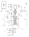
本実施形態のコンバインドサイクルプラントは、図1に示すように、ガスタービン10と、ガスタービン10から排気される燃焼ガスの熱で蒸気を発生する排熱回収ボイラー20と、排熱回収ボイラー20からの蒸気Sで駆動する蒸気タービン30と、各タービン10,30の駆動で発電する発電機40と、蒸気タービン30から排気された蒸気を水に戻す復水器23と、復水器23からの水を排熱回収ボイラー20に送る給水ポンプ25と、これらを制御する制御装置100と、を備えている。
As shown in FIG. 1, the combined cycle plant of this embodiment includes a
ガスタービン10は、外気Aを圧縮して圧縮空気を生成する圧縮機11と、燃料Fに圧縮空気を混合して燃焼させ高温の燃焼ガスを生成する燃焼器15と、燃焼ガスにより駆動するタービン16と、を備えている。
The
圧縮機11は、軸線を中心として回転する圧縮機ロータ12と、この圧縮機ロータ12を回転可能に覆う圧縮機ケーシング13と、この圧縮機ケーシング13内に吸い込まれる空気の流量を調節する吸気量調節器14と、を有する。吸気量調節器14は、圧縮機ケーシング13の吸込み口内に設けられているIGV(inlet guide vane)14aと、このIGV14aを駆動して、IGV14aの開度を調節する駆動器14bとを有する。
The
タービン16は、燃焼器15からの燃焼ガスにより、軸線を中心として回転するタービンロータ17と、このタービンロータ17を回転可能に覆うタービンケーシング18と、を有する。タービンロータ17と圧縮機ロータ12とは、同一の軸線を中心として回転するもので、相互に連結されて、ガスタービンロータ19を成している。タービン16の排気口は、排熱回収ボイラー20に接続されている。よって、タービン16から排気された燃焼ガスである排気ガスEGは、排熱回収ボイラー20に導かれる。
The
蒸気タービン30は、軸線を中心として回転する蒸気タービンロータ31と、この蒸気タービンロータ31を回転可能に覆う蒸気タービンケーシング32と、を有する。
The
この蒸気タービン30を起動させる際の起動モードとしては、例えば、蒸気タービン30に蒸気を投入する直前で、蒸気タービンケーシング32における蒸気入口側の蒸気接触部(例えば、第一段静翼環)の温度T2が、予め定められた第一温度(例えば、300℃)よりも低いコールドモードと、第一温度以上で予め定められた第二温度(例えば、400℃)よりも低いウォームモードと、第二温度以上のホットモードとがある。なお、以下では、ウォームモードとホットモードとを合わせた起動モードを通常起動モードとする。また、この蒸気タービン30を停止させる際のモードとしては、蒸気タービン30の停止時で、蒸気タービンケーシング32における前記蒸気接触部の温度T2が、予め定められた第四温度(例えば、150℃)よりも低い冷却停止モードと、第四温度以上の通常停止モードとがある。
As a start mode when starting the
発電機40は、軸線を中心として回転する発電機ロータ41と、この発電機ロータ41を回転可能に覆う発電機ケーシング42を有する。発電機ケーシング42は、発電機ロータ41の外周側に対向配置されるステータを有する。
The
ガスタービンロータ19、蒸気タービンロータ31、及び発電機ロータ41は、同一軸線上に並び、相互に連結されて、一体回転する。よって、本実施形態のコンバインドサイクルプラントは、一軸式のコンバインドサイクルプラントである。なお、本実施形態のコンバインドサイクルプラントは一軸式であるが、本発明はこれに限定されない。
The
ガスタービン10の燃焼器15には、燃料供給源からの燃料Fを燃焼器15に供給する燃料ライン51が接続されている。この燃料ライン51には、燃焼器15に流入する燃料Fの流量を調節する燃料流量調節弁52が設けられている。
A
蒸気タービン30の蒸気出口には、復水器23が設置されている。この復水器23と排熱回収ボイラー20の給水口とは、給水ライン24で接続されている。この給水ライン24には、前述の給水ポンプ25が設けられている。排熱回収ボイラー20の蒸気出口と蒸気タービン30の蒸気入口とは、蒸気ライン21で接続されている。この蒸気ライン21には、蒸気タービン30に流入する蒸気Sの流量を調節する蒸気流量調節弁22が設けられている。
A
蒸気ライン21中で、蒸気流量調節弁22よりも上流側(排熱回収ボイラー20側)には、この蒸気ライン21を通る蒸気Sの温度T1を検知する蒸気温度計61が設けられている。また、蒸気タービンケーシング32の蒸気入口側には、この蒸気タービンケーシング32の蒸気接触部(例えば、第一段静翼環)の温度T2を検知するメタル温度計62が設けられている。発電機40には、この発電機40での発電量、言い換えると、コンバインドサイクルプラントの出力PWを検知する出力計63が設けられている。発電機ロータ41、蒸気タービンロータ31、ガスタービンロータ19のいずれかには、ロータの回転数Nを検知する回転数計64が設けられている。
In the
制御装置100は、図2に示すように、燃料流量調節弁52の開度を制御する燃料制御器110と、吸気量調節器14の開度を制御するIGV制御器120と、蒸気流量調節弁22の開度を制御する蒸気制御器140と、蒸気タービン30の停止させるモードを冷却停止モードにするか否かを受け付ける停止モード受付器160と、を有する。
As shown in FIG. 2, the
燃料制御器110は、回転数計64で検知された回転数Nに応じた燃料流量を発生する第一燃料流量発生器111と、外部からの負荷指令及び出力計63で検知された出力PWに応じた燃料流量を発生する第二燃料流量発生器112と、第一燃料流量発生器111が発生した燃料流量と第二燃料流量発生器112が発生した燃料流量とのうち一方を選択的に出力する燃料流量切替器113と、燃料流量切替器113からの燃料流量の単位時間当たりの変化量である燃料流量変化率を制限する制限器114と、制限器114から出力された燃料流量に応じた燃料流量調節弁52の開度を示す指令を出力する指令出力器115と、を有する。
The fuel controller 110 includes a first fuel
第一燃料流量発生器111は、ガスタービンロータ19の回転数Nが例えば予め定められたパターンで増加するよう、各時刻における予定回転数等と燃料流量との関係を定めた関数Fx1を有している。第一燃料流量発生器111は、この関数Fx1を用いて、現時点での予定回転数が得られる燃料流量を定める。さらに、第一燃料流量発生器111は、回転数計64で検知された回転数Nと現時点での予定回転数との偏差がある場合には、先に定めた燃料流量を補正し、補正後の燃料流量を発生する。第二燃料流量発生器112は、外部からの負荷指令が示す出力及び出力計63で検知される出力PWと燃料流量との関係を定めた関数Fx2を有している。第二燃料流量発生器112は、この関数Fx2を用いて、外部からの負荷指令と出力計63で検知された出力PW等とに対応した燃料流量を発生する。
The first fuel
燃料流量切替器113は、ガスタービン10の起動開始時から外部から併入指令を受けるまでは、第一燃料流量発生器111からの燃料流量を出力し、外部から併入指令を受けると、第二燃料流量発生器112からの燃料流量を出力する。制限器114は、前述したように、燃料流量切替器113から出力された燃料流量の燃料流量変化率を所定値以下に制限する。指令出力器115は、制限器114から出力された燃料流量に応じた燃料流量調節弁52の開度を示す指令を作成し、この指令を燃料流量調節弁52に出力する。
The fuel
IGV制御器120は、吸気量調節器14の目的の第一開度G1を発生する第一開度発生器121と、吸気量調節器14の目的の第二開度G2を発生する第二開度発生器122と、ガスタービン起動時における吸気量調節器14の開度であるガスタービン起動時開度Gnを発生するガスタービン起動時開度発生器123と、第一開度G1と第二開度G2とのうち一方の開度を選択的に出力する第一切替器124と、第一切替器124が出力した開度とガスタービン起動時開度Gnとのうち一方の開度を選択的に出力する第二切替器125と、第二切替器125から出力された開度の単位時間当たりの変化量である開度変化率を制限する制限器126と、蒸気タービン30のモードを認識するモード認識部127と、制限器126から出力された開度を示す指令を吸気量調節器14に出力する指令出力器128と、第一切替器124に対して切替指令を出力する第一切替指令発生器131a,131bと、第二切替器125に対して切替指令を出力する第二切替指令発生器132と、を有する。
The IGV controller 120 includes a first
第二開度発生器122は、出力計63で検知される出力PWと吸気量調節器14の第二開度G2との関係を定めた関数Gx2を有している。この関数Gx2は、図3に示すように、出力計63で検知される出力PWが予め定められた出力PW1までは、第二開度G2として、一定の開度bを示す。また、関数Gx2は、出力計63で検知される出力PWが予め定められた出力PW1以上になると、第二開度G2として、出力PWの変化に対して正の相関性を持つ開度を示す。第二開度発生器122は、この関数Gx2を用いて、出力計63で検知された出力に応じた第二開度G2を発生する。なお、この第二開度発生器122は、後述の第三開度を発生する第三開度発生器、後述の第五開度を発生する第五開度発生器、さらに、後述の第六開度を発生する第六開度発生器としても機能する。但し、この第二開度発生器122は、第三開度発生器として機能する場合でも、第五開度発生器として機能する場合でも、第六開度発生器として機能する場合でも、関数Gx2を用いて、出力計63で検知された出力に応じた開度を発生する。
The
第一開度発生器121は、出力計63で検知される出力PWと吸気量調節器14の第一開度G1との関係を定めた関数Gx1を有している。この関数Gx1は、図3に示すように、出力計63で検知される出力PWが前述の出力PW1未満までの第一開度G1を示す。この関数Gx1は、第一開度G1として、出力計63で検知される出力PWが0から前述の出力PW1未満までの間、一定の開度cを示す。この開度cは、前述の開度bよりも大きい。第一開度発生器121は、この関数Gx1を用いて、出力計63で検知された出力に応じた第一開度G1を発生する。なお、この第一開度発生器121は、後述の第四開度を発生する第四開度発生器としても機能する。但し、この第一開度発生器121は、第四開度発生器として機能する場合でも、関数Gx1を用いて、開度を発生する。
The first
ガスタービン起動時開度発生器123は、起動時におけるガスタービン10の回転数Nと吸気量調節器14の開度との関係を定めた関数Gxnを有している。この関数Gxnは、図4に示すように、ガスタービン10の定格回転数N1までの開度を示す。この関数Gxnは、回転数計64で検知される回転数Nが予め定められた回転数N0までは、一定の開度aを示す。この予め定められた回転数N0は、定格回転数N1よりも小さな回転数である。また、関数Gxnは、回転数計64で検知される回転数Nが予め定められた回転数N0以上になると、回転数Nの変化に対して正の相関性を持つ開度を示し、回転数Nの増加に伴って、開度aから徐々に大きくなる。なお、この関数Gxnでは、回転数計64で検知される回転数Nが定格回転数N1に対応する開度が前述の開度bである。
The
モード認識部127は、メタル温度計62で検知された温度T2に応じて、蒸気タービン30の起動モードがコールドモードであるか通常起動モードであるかを認識する。具体的に、メタル温度で検知された蒸気タービンケーシング32の蒸気接触部の温度T2が、前述の第一温度(例えば、300℃)よりも低いときにはコールドモードであると認識し、この第一温度以上のときには通常起動モードであると認識する。また、モード認識部127は、停止モード受付器160の入力操作に応じて、蒸気タービン30の停止モードが冷却停止モードであるか通常停止モードであるかを認識する。
The
第一切替指令発生器131a,131bは、コールドモードにおける開度制御及び冷却停止モードにおける開度制御への切替指令「1」を発生する第一a切替指令発生器131aと、コールドモードにおける開度制御終了の切替指令「0」を発生する第一b切替指令発生器131bとがある。第一a切替指令発生器131aは、モード認識部127により起動モードがコールドモードであると認識されると、コールドモードにおける開度制御への切替指令「1」を発生する。また、第一a切替指令発生器131aは、モード認識部127により停止モードが冷却停止モードであると認識され、且つ出力計63で検知された出力PWが予め定められた出力PW1以下になると、冷却停止モードによる開度制御への切替指令「1」を発生する。第一b切替指令発生器131bは、モード認識部127により起動モードがコールドモードであると認識され、且つ蒸気流量調節弁22が閉から開になるときに、コールドモードにおける開度制御終了の切替指令「0」を発生する。
The first
第一切替器124は、第一a切替指令発生器131aがコールドモードにおける開度制御及び冷却停止モードにおける開度制御への切替指令「1」を発生すると、第一開度G1と第二開度G2とのうち第一開度G1を出力する。また、第一切替器124は、第一b切替指令発生器131bがコールドモードにおける開度制御終了の切替指令「0」を発生すると、第一開度G1と第二開度G2とのうち第二開度G2を出力する。
When the first
第二切替指令発生器132は、回転数計64で検知された回転数Nが定格回転数N1未満のとき、ガスタービン起動時における開度制御への切替指令「1」を発生する。第二切替器125は、第二切替指令発生器132がガスタービン起動時における開度制御への切替指令「1」を発生すると、ガスタービン起動時開度発生器123からのガスタービン起動時開度Gnと第一切替器124からの開度とうち、ガスタービン起動時開度発生器123からのガスタービン起動時開度Gnを出力する。また、第二切替指令発生器132は、回転数計64で検知された回転数Nが定格回転数N1以上になると、ガスタービン起動時における開度制御終了の切替指令「0」を発生する。第二切替器125は、第二切替指令発生器132がガスタービン起動時における開度制御終了の切替指令「0」を発生すると、ガスタービン起動時開度発生器123からのガスタービン起動時開度Gnと第一切替器124からの開度とうち第一切替器124からの開度を出力する。
The second
制限器126は、前述したように、第二切替器125から出力された開度の変化率を予め定められた変化率以下に制限する。この予め定められた変化率は、コンバインドサイクルプラントの状態に応じて変更される。
As described above, the
指令出力器128は、前述したように、制限器126で変化率が制限された開度を示す指令を吸気量調節器14に出力する。
As described above, the
蒸気制御器140は、蒸気流量調節弁22の開条件が成立したか否かを判断する開条件判断部141と、蒸気流量調節弁22の閉条件が成立したか否かを定める閉条件判断部151と、蒸気流量調節弁22を開ける過程での開度を発生する開時開度発生器155と、蒸気流量調節弁22を閉じる過程での開度を発生する閉時開度発生器156と、開時開度発生器155が発生した開度又は閉時開度発生器156が発生した開度に応じた指令を蒸気流量調節弁22に出力する指令出力器157と、を有する。
The steam controller 140 includes an open
開条件判断部141は、減算器142と、第一判断器143と、第二判断器144と、第三判断器145と、第四判断器146と、OR回路147と、第一AND回路148と、第二AND回路149と、を有する。
The open
減算器142は、蒸気温度計61で検知された蒸気ライン21中の蒸気Sの温度T1とメタル温度計62で検知された蒸気タービンケーシング32の蒸気接触部の温度T2との温度偏差ΔT(=T1−T2)を求める。第一判断器143は、蒸気Sの温度T1が(現状の蒸気圧力の飽和温度+特定過熱度)Te以上であると、蒸気Sの温度T1は蒸気流量調節弁22を開けるための下限値が成立しているとして「1」を出力する。第二判断器144は、蒸気Sの温度T1が予め定められた上限温度Tmax以下であると、蒸気Sの温度T1は蒸気流量調節弁22を開けるための上限値が成立しているとして「1」を出力する。第三判断器145は、温度偏差ΔTが予め定められた温度偏差ΔTmax以下であると、温度偏差ΔTは蒸気流量調節弁22を開けるための上限値が成立しているとして「1」を出力する。第四判断器146は、温度偏差ΔTが予め定められた温度偏差ΔTmin(ΔTminは負の値)以上であると、温度偏差ΔTは蒸気流量調節弁22を開けるための下限値が成立しているとして「1」を出力する。OR回路147は、第二判断器144又は第三判断器145が「1」を出力すると、「1」を出力する。第一AND回路148は、第四判断器146が「1」を出力し且つOR回路147が「1」を出力すると、「1」を出力する。第二AND回路149は、第一判断器143が「1」を出力し且つ第一AND回路148が「1」を出力すると、「1」を出力する。
The
すなわち、開条件判断部141の第二AND回路149は、以下の温度条件(1)(2)を満たした場合に、蒸気流量調節弁22の開条件が成立したとして、「1」を出力する。
(1)温度の上限値
蒸気Sの温度T1が予め定められた上限温度Tmax以下である、又は、温度偏差ΔTが予め定められた温度偏差ΔTmax以下である。
(2)温度の下限値
蒸気Sの温度T1が(現状の蒸気圧力の飽和温度+特定過熱度)Te以上である、又は、温度偏差ΔTが予め定められた温度偏差ΔTmin(ΔTminは負の値)以上である。
That is, the second AND
(1) Upper limit value of temperature The temperature T1 of the steam S is not more than a predetermined upper limit temperature Tmax, or the temperature deviation ΔT is not more than a predetermined temperature deviation ΔTmax.
(2) Lower temperature limit The temperature T1 of the steam S is equal to or higher than (the current steam pressure saturation temperature + specific superheat degree) Te, or the temperature deviation ΔT is a predetermined temperature deviation ΔTmin (ΔTmin is a negative value) ) That's it.
以上のように、本実施形態では、蒸気流量調節弁22の開条件、つまり蒸気タービン30への蒸気供給開始条件として、蒸気ライン21中の蒸気Sの温度T1と蒸気タービンケーシング32の蒸気接触部の温度T2との温度偏差ΔTの上下限値を定めている。これは、蒸気タービン30への蒸気供給開始時に、蒸気タービン30での熱応力の発生を抑えるためである。
As described above, in the present embodiment, the temperature T1 of the steam S in the
開時開度発生器155は、開条件判断部141から「1」が出力されると、予め定められた変化率で大きくなる開度を発生する。なお、この変化率は、各種条件に応じて変更してもよい。
When the opening
閉条件判断部151は、第五判断器152を有する。この第五判断器152は、コンバインドサイクルプラントの停止を示す負荷指令が外部から入力された後、出力計63で検知される出力PWが予め定められた出力PW1以下になると、蒸気流量調節弁22の閉条件が成立したとして、「1」を出力する。
The closing
閉時開度発生器156は、閉条件判断部151から「1」が出力されると、予め定められた変化率で小さくなる開度を発生する。なお、この変化率は、各種条件に応じて変更してもよい。例えば、停止モードが通常停止モードのときには変化率を大きくし、冷却停止モードのときには変化率を小さくしてもよい。
When the closing
指令出力器157は、前述したように、開時開度発生器155が発生した開度又は閉時開度発生器156が発生した開度に応じた指令を蒸気流量調節弁22に出力する。
As described above, the
なお、本実施形態の制御装置100は、コンピュータで構成されており、制御装置100の各部の処理は、いずれも、ハードディスクドライブ装置等の外部記憶装置やメモリ等の記憶装置と、この記憶装置に記憶されているプログラムを実行するCPUとを有して構成されている。
Note that the
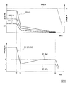
次に、本実施形態のコンバインドサイクルプラントの起動過程における動作について、図5に示すタイミングチャートに従って説明する。 Next, the operation | movement in the starting process of the combined cycle plant of this embodiment is demonstrated according to the timing chart shown in FIG.
制御装置100が外部からコンバインドサイクルプラントの起動を示す負荷指令を受け付けると、図示されていない起動装置に対して起動指令を出力し、この起動装置を起動させる。この起動装置の起動により、ガスタービン10の圧縮機ロータ12及びタービンロータ17が一体的に回転し始める。圧縮機ロータ12が回転すると、圧縮機11からの圧縮空気が燃焼器15に供給され始められる。圧縮機ロータ12及びタービンロータ17、つまりガスタービンロータ19が例えば予め定められた回転数N0になると(t0)、制御装置100の燃料制御器110は、燃料流量調節弁52に対して開指令を出力する。この結果、燃料ライン51からの燃料Fが燃料流量調節弁52を介して燃焼器15に供給され始められる。この燃料Fは、圧縮機11から燃焼器15に供給された圧縮空気中で燃焼する。燃焼器15で発生した燃焼ガスは、タービン16に流れ込み、ガスタービンロータ19を回転させる。
When the
燃焼器15への燃料供給開始時、燃料制御器110の第一燃料流量発生器111からの燃料流量が燃料流量切替器113を介して、制限器114に送られる。第一燃料流量発生器111は、前述したように、関数Fx1を用いて、現時点での予定回転数が得られる燃料流量を定める。さらに、第一燃料流量発生器111は、回転数計64で検知された回転数Nと現時点での予定回転数との偏差がある場合には、先に定めた燃料流量を補正し、補正後の燃料流量を発生する。制限器114は、燃料流量の変化率が予め定められた変化率以下になるよう、第一燃料流量発生器111からの燃料流量の変化率を制限し、これを出力する。指令出力器115は、燃料流量調節弁52に対して、制限器114から出力された燃料流量に応じた開度を示す指令を出力する。
When the fuel supply to the
この結果、ガスタービンロータ19の回転数Nは、基本的に予め定められたパターンで増加する。
As a result, the rotational speed N of the
IGV制御器120の第二切替指令発生器132は、回転数計64で検知される回転数Nが定格回転数N1未満のとき切替指令「1」を発生している。IGV制御器120の第二切替器125は、切替指令「1」を受けて、ガスタービン起動時開度発生器123からの開度と第一切替器124からの開度とのうち、ガスタービン起動時開度発生器123からの開度を制限器126に送る。よって、燃焼器15への燃料供給開始時、つまり回転数計64で検知される回転数Nが定格回転数N1未満のとき、IGV制御器120のガスタービン起動時開度発生器123からの開度が第二切替器125を介して、制限器126に送られる。ガスタービン起動時開度発生器123は、関数Gxnを用いて、回転数計64で検知された回転数Nに応じた開度をガスタービン起動時開度Gnとして発生する。ガスタービン起動時開度発生器123が発生する開度は、図4を用いて前述したように、回転数計64で検知される回転数Nが予め定められた回転数N0になるまで(t0)、一定の開度aである。また、ガスタービン起動時開度発生器123が発生する開度は、回転数計64で検知される回転数Nが予め定められた出力N0以上になると(t0)、回転数Nの変化に対して正の相関性を持って変化する。つまり、ガスタービン起動時開度発生器123が発生する開度は、回転数Nの増加に伴って増加する。制限器126は、吸気量調節器14の開度の変化率が予め定められた変化率以下になるよう、ガスタービン起動時開度発生器123からの開度の変化率を制限し、これを出力する。指令出力器128は、吸気量調節器14に対して、制限器126から出力された開度を示す指令を出力する。吸気量調節器14の開度は、ガスタービンロータ19の回転数Nが定格回転数N1になる直前で、開度bになる。
The second
IGV制御器120のモード認識部127は、メタル温度計62で検知される蒸気タービンケーシング32の温度T2に応じて、蒸気タービン30の起動モードがコールドモードであるか通常起動モードであるかを認識する(起動モード認識工程)。第一a切替指令発生器131aは、モード認識部127により起動モードが通常起動モードであると認識されると、通常起動モードにおける開度制御への切替指令「0」を発生する。第一切替器124は、第一a切替指令発生器131aから切替指令「0」を受けると、第一開度発生器121からの第一開度G1と第二開度発生器122からの第二開度G2とのうち、第二開度発生器122からの第二開度G2を出力する。この第二開度G2は、図3を用いて前述したように、出力計63で検知される出力PWが予め定められた出力PW1までは一定の開度bで、出力計63で検知される出力PWが予め定められた出力PW1以上になると、出力PWの変化に対して正の相関性を持つ開度になる。
The
ガスタービンロータ19の回転数Nは、出力計63で検知される出力PWが予め定められた出力PW1以上になる以前に定格回転数N1になる(t1)。第二切替指令発生器132は、回転数計64で検知される回転数Nが定格回転数N1以上になると(t1)、切替指令「0」を発生する。第二切替器125は、この切替指令「0」を受けると、ガスタービン起動時開度発生器123からの開度と第一切替器124からの開度とのうち、第一切替器124からの開度、つまり、第一開度発生器121が発生した第一開度G1又は第二開度発生器122が発生した第二開度G2を制限器126に送る。この場合(通常起動モードの場合)、第二切替器125は、第二開度発生器122が発生した第二開度G2を制限器126に送る。制限器126は、吸気量調節器14の開度の変化率が予め定められた変化率以下になるよう、第二開度発生器122からの開度の変化率を制限し、これを出力する。指令出力器128は、吸気量調節器14に対して、制限器126から出力された開度を示す指令を出力する(指令出力工程)。
The rotational speed N of the
第一a切替指令発生器131aは、モード認識部127により起動モードがコールドモードであると認識されると、コールドモードにおける開度制御への切替指令「1」を発生する。第一切替器124は、第一a切替指令発生器131aから切替指令「1」を受けると、第一開度発生器121からの第一開度G1と第二開度発生器122からの第二開度G2とのうち、第一開度発生器121からの第一開度G1を出力する。この第一開度G1は、図3を用いて前述したように、通常起動モードのときの開度bよりも大きい一定の開度cである。
When the
前述したように、第二切替指令発生器132は、回転数計64で検知される回転数Nが定格回転数N1以上になると(t1)、切替指令「0」を発生する。第二切替器125は、この切替指令「0」を受けると、ガスタービン起動時開度発生器123からの開度と第一切替器124からの開度とのうち、第一切替器124からの開度からの開度、つまり、第一開度発生器121が発生した第一開度G1又は第二開度発生器122が発生した第二開度G2を制限器126に送る。この場合(コールドモードの場合)、第二切替器125は、第一開度発生器121が発生した第一開度G1である開度cを制限器126に送る。第二切替器125が切り替えられる直前の開度は、ガスタービンロータ19が定格回転数N1のときのガスタービン起動時開度Gnである開度bである。一方、第二切替器125が切り替えられた直後の開度は、開度bよりも大きい第一開度G1である開度cである。制限器126は、吸気量調節器14の開度の変化率が予め定められた変化率以下になるよう、第二開度発生器122からの開度の変化率を制限する。すなわち、制限器126は、第二切替器125の切替前の開度bから徐々に開度cへの大きくなるよう、第二開度発生器122からの開度の変化率を制限する。制限器126は、出力している開度が開度cになると、この開度cを出力し続ける。指令出力器128は、吸気量調節器14に対して、制限器126から出力された開度を示す指令を出力する(指令出力工程)。
As described above, the second
ガスタービンロータ19の回転数Nが定格回転数N1になり、且つ所定の条件を満たすと、外部から制御装置100に、発電機40と外部の系統電力との電気的な接続を指示する併入指令が入力する(t2)。この併入指令が入力すると(t2)、遮断器が閉じて、発電機40と外部の系統電力とが電気的に接続される。この結果、この時点(t2)から、出力計63からの出力PWが得られるようになる。また、発電機40が系統電力線に接続されると、以降、ガスタービンロータ19の回転数は、この定格回転数N1に維持される。さらに、燃料制御器110の燃料流量切替器113は、この併入指令を受け付けると、第一燃料流量発生器111からの燃料流量と第二燃料流量発生器112からの燃料流量とのうち、第二燃料流量発生器112からの燃料流量を出力するようになる。第二燃料流量発生器112は、前述したように、関数Fx2を用いて、外部からの負荷指令と出力計63で検知された出力PW等とに対応した燃料流量を発生する。第二燃料流量発生器112からの燃料流量は、燃料流量切替器113を介して、制限器114に送られる。制限器114は、前述したように、燃料流量切替器113から出力された燃料流量の燃料流量変化率を所定値以下に制限する。指令出力器115は、制限器114から出力された燃料流量に応じた開度を示す指令を作成し、この指令を燃料流量調節弁52に出力する。
When the rotational speed N of the
外部からの負荷指令は、蒸気タービン30への蒸気供給開始条件が成立するまで、基本的に一定である。このため、燃料流量調節弁52の開度は、併入後、蒸気タービン30への蒸気供給開始条件が成立するまでの間、一定で、この間の出力PWも一定のPW1である。外部からの負荷指令は、蒸気タービン30への蒸気供給開始条件が成立すると(t3)、負荷指令が示す負荷の値が徐々に増加する。このため、燃料流量調節弁52の開度は、蒸気タービン30への蒸気供給開始条件が成立すると(t3)、徐々に大きくなり、出力PWも徐々に大きくなる。以降、ガスタービン10を停止させるまでの間、燃料流量調節弁52は、第二燃料流量発生器112からの燃料量流量に応じた開度に制御させる。
The load command from the outside is basically constant until the condition for starting the supply of steam to the
ガスタービン10の燃焼器15に燃料が供給され始められると、排熱回収ボイラー20から発生する蒸気の流量が徐々に増加すると共に、蒸気の温度が徐々に高まる。そして、発電機40が併入された後、蒸気タービン30に供給する蒸気の蒸気供給開始条件が成立する。
When fuel is started to be supplied to the
蒸気供給開始条件が成立すると、蒸気制御器140の開条件判断部141から「1」が出力される(t3)。開条件判断部141から「1」が出力されると、開時開度発生器155は、開条件判断部141から「1」が出力されると、予め定められた変化率で大きくなる開度を発生する。蒸気制御器140の指令出力器157は、この開度を示す指令を蒸気流量調節弁22に出力する。この結果、閉状態の蒸気流量調節弁22が徐々に開き始め、蒸気タービン30に蒸気が供給され始められ、蒸気タービン30の出力も出力計63で検知される出力に加わるようになる。
When the steam supply start condition is satisfied, “1” is output from the open
IGV制御器120の第一b切替指令発生器131bは、モード認識部127により起動モードがコールドモードであると認識され、且つ蒸気制御器140の開条件判断部141が蒸気供給開始条件が成立したとして「1」を出力すると(t3)、コールドモードにおける開度制御終了の切替指令「0」を発生する。第一切替器124は、第一b切替指令発生器131bから切替指令「0」を受けると、第一開度発生器121からの第一開度G1と第二開度発生器122からの第二開度G2とのうち、第二開度発生器122からの第二開度G2を出力する。なお、この際、第一切替器124は、第三切替器として機能している。この第二開度G2は、第二切替器125を介して、制限器126に送られる。第一切替器(第三切替器)124が切り替えられる直前の開度は、第一開度G1である開度cである。一方、第一切替器(第三切替器)124が切り替えられた直後の開度は、第二開度発生器122が発生した第二開度G2である開度bである。制限器126は、吸気量調節器14の開度の変化率が予め定められた変化率以下になるよう、第二開度発生器122からの開度の変化率を制限する。すなわち、制限器126は、第二切替器125の切替前の開度cから徐々に開度bへ小さくなるよう、第二開度発生器122からの開度の変化率を制限する。なお、この際の開度の変化率は、回転数計64で検知される回転数Nが定格回転数N1以上になり(t1)、開度bから開度cに切り替わるときの開度の変化率と異ならせてもよい。この場合、制限器126は、第一b切替指令発生器131bから切替指令「0」を受けて、開度の変化率を変更する。以降、ガスタービン10と共に蒸気タービン30を停止させる制御が開始されるまで、吸気量調節器14の開度は、第二開度発生器122が発生した第二開度G2に制御される。なお、第一切替器124が切り替えられた直後、第二開度発生器122は、前述の第三開度発生器として機能する。第二開度発生器122は、第三開度発生器として機能している場合、第二開度G2を第三開度G3として出力していることになる。
The first b switching
前述したように、本実施形態では、蒸気流量調節弁22の開条件、つまり蒸気タービン30への蒸気供給開始条件として、蒸気ライン21中の蒸気Sの温度T1と蒸気タービンケーシング32の蒸気接触部の温度T2との温度偏差ΔTの上下限値を定めている。近年、ガスタービン10の効率化に伴い、ガスタービン10のタービン16における燃焼ガスの温度が高まっている関係で、蒸気温度も高まっている。このため、蒸気タービンケーシング32の蒸気接触部の温度T2が予め定められた温度(例えば、300℃)よりも低いコールドモードときには、蒸気ライン21中の蒸気Sの温度T1と蒸気タービンケーシング32の蒸気接触部の温度T2との温度偏差ΔTが大きくなる。よって、この温度偏差ΔTが蒸気供給開始条件の一つである上下限値の範囲内に収まらない可能性が高くなる。
As described above, in the present embodiment, the temperature T1 of the steam S in the
そこで、本実施形態では、蒸気タービン30の起動モードがコールドモードの場合には、通常起動モードの場合よりも、吸気量調節器14の開度を大きくしている。ガスタービン10の燃焼器15に供給する燃料の流量制御は、本実施形態において、コールドモードの場合と通常起動モードの場合とで同じである。このため、本実施形態では、ガスタービン10に供給される燃料流量に対する空気流量が、通常起動モードの場合よりも、コールドモードの場合の方が多くなる。よって、本実施形態では、通常起動モードの場合よりも、コールドモードの場合の方が燃焼ガスの温度が低くなり、蒸気の温度も低くなる。本実施形態では、このように、蒸気タービンケーシング32の蒸気接触部の温度T2が予め定められた温度よりも低いコールドモードの場合、通常起動モードの場合よりも蒸気の温度も低くなるため、蒸気Sの温度T1と蒸気接触部の温度T2との温度偏差ΔTを抑えることができる。
Therefore, in the present embodiment, when the start mode of the
よって、本実施形態では、コールドモードの場合でも、容易に蒸気供給開始条件を満たすことができる。 Therefore, in the present embodiment, the vapor supply start condition can be easily satisfied even in the cold mode.
また、本実施形態では、第一開度発生器121からの第一開度G1と第二開度発生器122からの第二開度G2とを使い分けることで、コールドモードの場合の開度制御と通常起動モードの場合の開度制御とを実行している。このため、本実施形態では、蒸気タービン30への蒸気供給開始前における吸気量調節器14の開度制御を簡易な方法で行うことができる。言い換えると、本実施形態では、蒸気タービン30への蒸気供給開始前における吸気量調節器14の開度制御を実行するIGV制御器120の構成を簡易化することができる。
In the present embodiment, the opening degree control in the cold mode is performed by properly using the first opening degree G1 from the first
さらに、本実施形態では、各開度発生器から発生される開度のうち、一の開度から他の開度へ切り替える際に、一の開度と他の開度との偏差がある場合でも、一の開度から他の開度へ徐々に開度を変更するので、開度切替時における制御系の混乱を抑えることができる。よって、本実施形態では、以上のように、第一開度発生器121からの第一開度G1と第二開度発生器122からの第二開度G2とを使い分けても、制御系の混乱を抑えることができる。
Furthermore, in the present embodiment, when switching from one opening to another opening among the opening generated from each opening generator, there is a deviation between one opening and another opening However, since the opening is gradually changed from one opening to another, the confusion of the control system at the time of opening switching can be suppressed. Therefore, in the present embodiment, as described above, even if the first opening G1 from the
次に、本実施形態のコンバインドサイクルプラントの停止過程における動作について、図6に示すタイミングチャートに従って説明する。 Next, the operation | movement in the stop process of the combined cycle plant of this embodiment is demonstrated according to the timing chart shown in FIG.
ガスタービン10及び蒸気タービン30が定常運転されている際、燃料流量調節弁52は、燃料制御器110の第二燃料発生器から発生された燃料流量に応じた開度に制御される。また、吸気流量調節器は、IGV制御器120の第二開度発生器122から発生された第二開度G2に応じた開度に制御される。なお、この際、第二開度発生器122は、前述の第三開度発生器、第六開度発生器として機能する。第二開度発生器122は、第三開度発生器として機能している場合、第二開度G2を第三開度G3として出力していることになり、第六開度発生器として機能している場合、第二開度G2を第六開度G6として出力していることになる。また、蒸気流量調節弁22は、基本的に全開状態に維持されている。
When the
オペレータは、コンバインドサイクルプラントを停止させる以前に、制御装置100の停止モード受付器160を操作して、制御装置100に対して、蒸気タービン30の停止モードを冷却停止モードにするか通常停止モードにするかを入力する。モード認識部127は、この停止モード受付器160の操作結果に応じて、蒸気タービン30の停止モードが冷却停止モードであるか通常停止モードであるかを認識する(停止モード認識工程)。
Before stopping the combined cycle plant, the operator operates the
制御装置100が外部からコンバインドサイクルプラントの停止を示す負荷指令を受け付けると(t6)、燃料制御器110の第二燃料流量発生器112は、この負荷指令に含まれる負荷に応じた燃料流量を出力するようになる。すなわち、第二燃料流量発生器112は、徐々に小さくなる燃料流量を出力するようになる。このため、ガスタービン10の出力が徐々に低下すると共に、蒸気タービン30の出力も徐々に低下する。
When the
蒸気制御器140における閉条件判断部151の第五判断器152は、コンバインドサイクルプラントの停止を示す負荷指令が外部から入力された後、出力計63で検知される出力PWが予め定められた出力PW1以下になると(t7)、蒸気流量調節弁22の閉条件が成立したとして、「1」を出力する。閉時開度発生器156は、閉条件判断部151から「1」が出力されると、予め定められた変化率で小さくなる開度を発生する。指令出力器157は、前述したように、閉時開度発生器156が発生した開度に応じた指令を蒸気流量調節弁22に出力する。このため、蒸気流量調節弁22の開度は、以降、徐々に小さくなる。
The
出力計63で検知される出力PWが予め定められた出力PW1以下になり、蒸気制御器140における閉条件判断部151が、蒸気流量調節弁22の閉条件が成立したとして「1」を出力すると(t7)、この出力「1」は、IGV制御器120の第一a切替指令発生器131aにも入力する。第一a切替指令発生器131aは、モード認識部127が通常停止モードであると認識している場合に、蒸気制御器140における閉条件判断部151から蒸気流量調節弁22の閉条件が成立したことを意味する「1」を受け付けると(t7)、切替指令「0」を発生する。第一切替器124は、第一切替器124は、この切替指令「0」を受けると、第一開度G1と第二開度G2とのうち第二開度G2を出力する(指令出力工程)。なお、第一切替器124は、ガスタービン10及び蒸気タービン30が定常運転されている際、第一開度G1と第二開度G2とのうち第二開度G2を出力するので、この時点で、第一切替器124が切替指令「0」を受けても、この切替指令「0」を受ける前後で、出力する開度は変わらず、第二開度G2のままである。また、第一切替器124が切り替えられた直後、第二開度発生器122は、前述の第五開度発生器として機能する。第二開度発生器122は、第五開度発生器として機能している場合、第二開度G2を第五開度G5として出力していることになる。
When the output PW detected by the
よって、停止モードが通常停止モードである場合に、蒸気流量調節弁22の閉条件が成立した以降でも、第二開度発生器122で発生された第二開度G2に応じた指令が吸気量調節器14に送られる。この第二開度発生器122が有している関数Gx2は、図3を用いて前述したように、基本的に、第二開度G2として、出力PWの変化に対して正の相関性を持つ開度を示す。但し、この関数Gx2は、出力計63で検知される出力PWが予め定められた出力PW1以下の場合、一定の開度bを示す。このため、出力計63で検知される出力PWが予め定められた出力PW1以下になり、蒸気流量調節弁22の閉条件が成立した以降(t7)、第一切替器124から出力される第二開度G2は一定の開度bである。この一定の開度bは、制限器126を介して指令出力器128に送られる。指令出力器128は、この一定の開度bを示す指令を吸気量調節器14に出力する。
Therefore, when the stop mode is the normal stop mode, the command corresponding to the second opening G2 generated by the
制御装置100が外部から、発電機40と外部の系統電力との電気的な接続を絶つ旨の指示である解列指令が入力すると(t8)、遮断器が開いて、発電機40と外部の系統電力との電気的な接続が絶たれる。この結果、この時点(t8)から、出力計63からの出力PWは0になる。
When the
一方、モード認識部127が冷却停止モードであると認識している場合に、出力計63で検知される出力PWが予め定められた出力PW1以下になり、蒸気制御器140における閉条件判断部151が、蒸気流量調節弁22の閉条件が成立したとして「1」を出力すると(t7)、第一a切替指令発生器131aは、冷却停止モードにおける開度制御への切替指令「1」を発生する。第一切替器124は、この切替指令「1」を受けると、第一開度G1と第二開度G2とのうち第一開度G1である一定の開度cを出力する。この第一開度G1は、第二切替器125を介して、制限器126に送られる。第一切替器124が切り替えられる直前の開度は、開度bである。一方、第一切替器124が切り替えられた直後の開度は、第一開度発生器121が発生した第一開度G1である一定の開度cである。制限器126は、吸気量調節器14の開度の変化率が予め定められた変化率以下になるよう、第一開度発生器121からの開度の変化率を制限する。すなわち、制限器126は、第二切替器125の切替前の開度bから徐々に開度cへ大きくなるよう、第一開度発生器121からの開度の変化率を制限する。なお、この際の開度の変化率は、回転数計64で検知される回転数Nが定格回転数N1以上になり(t1)、開度bから開度cに切り替わるときの開度の変化率と異ならせてもよい。この場合、制限器126は、第一a切替指令発生器131aからの切替指令「1」を受けて、開度の変化率を変更する。制限器126は、出力している開度が開度cになると、この開度cを出力し続ける。指令出力器128は、吸気量調節器14に対して、制限器126から出力された開度を示す指令を出力する(指令出力工程)。なお、第一切替器124が切り替えられた直後、第一開度発生器121は、前述の第四開度発生器として機能する。第一開度発生器121は、第四開度発生器として機能している場合、第一開度G1を第四開度G4として出力していることになる。
On the other hand, when the
以上、本実施形態では、蒸気タービン30の停止モードが冷却停止モードの場合、通常停止モードの場合よりも、吸気量調節器14の開度を大きくしている。一方、本実施形態では、ガスタービン10の燃焼器15に供給する燃料の流量制御が、冷却停止モードの場合と通常停止モードの場合とで同じである。このため、本実施形態では、ガスタービン10に供給される燃料流量に対する空気流量が、通常停止モードの場合よりも、冷却停止モードの場合の方が多くなる。よって、本実施形態では、通常停止モードの場合よりも、冷却停止モードの場合の方が燃焼ガスの温度が低くなり、蒸気の温度も低くなる。本実施形態では、このように、蒸気タービン30の停止モードとして冷却停止モードが選択された場合、通常停止モードの場合よりも蒸気の温度も低くなるため、蒸気タービン30の温度を短時間で低くすることができる。
As described above, in the present embodiment, when the stop mode of the
また、本実施形態では、第一開度発生器121からの第一開度G1と第二開度発生器122からの第二開度G2とを使い分けることで、冷却停止モードの場合の開度制御と通常停止モードの場合の開度制御とを実行している。このため、本実施形態では、蒸気タービン30の停止過程における吸気量調節器14の開度制御を簡易な方法で行うことができる。言い換えると、本実施形態では、蒸気タービン30の停止過程における吸気量調節器14の開度制御を実行するIGV制御器120の構成を簡易化することができる。
In the present embodiment, the first opening G1 from the
さらに、本実施形態では、蒸気タービン30への蒸気供給開始前における吸気量調節器14の開度制御の場合と同様、各開度発生器から発生される開度のうち、一の開度から他の開度へ切り替える際に、一の開度と他の開度との偏差がある場合でも、一の開度から他の開度へ徐々に開度を変更するので、開度切替時における制御系の混乱を抑えることができる。よって、本実施形態では、蒸気タービン30への蒸気供給開始前における吸気量調節器14の開度制御の場合と同様、第一開度発生器121からの第一開度G1と第二開度発生器122からの第二開度G2とを使い分けても、制御系の混乱を抑えることができる。
Furthermore, in the present embodiment, as in the case of the opening degree control of the intake
なお、以上の実施形態では、第一開度発生器121が独自の関数Gx1を有し、この関数Gx1を用いて第一開度G1を発生している。しかしながら、第一開度発生器は、第二開度発生器が発生した第二開度G2に予め定められた値を加算するものであってもよい。
In the above embodiment, the
また、以上の実施形態では、起動モードがコールドモードのときに採用される第一開度G1と、停止モードが冷却停止モードのときに採用される第一開度G1とは、同一のものである。しかしながら、起動モードがコールドモードのときに採用される第一開度G1と、停止モードが冷却停止モードのときに採用される開度とは、同一でなくてもよい。 In the above embodiment, the first opening G1 employed when the start mode is the cold mode and the first opening G1 employed when the stop mode is the cooling stop mode are the same. is there. However, the first opening degree G1 adopted when the start mode is the cold mode and the opening degree adopted when the stop mode is the cooling stop mode may not be the same.
10:ガスタービン、11:圧縮機、14:吸気量調節器、15:燃焼器、20:排熱回収ボイラー、21:蒸気ライン、22:蒸気流量調節弁、23:復水器、24:給水ライン、30:蒸気タービン、40:発電機、51:燃料ライン、52:燃料流量調節弁、61:蒸気温度計、62:メタル温度計、63:出力計、64:回転数計、100:制御装置、110:燃料制御器、120:IGV制御器、121:第一開度発生器(第四開度発生器)、122:第二開度発生器(第三開度発生器、第五開度発生器、第六開度発生器)、124:第一切替器(第三切替器)、125:第二切替器、126:制限器、127:モード認識部、128:指令出力器、140:蒸気制御器、160:停止モード受付器 10: Gas turbine, 11: Compressor, 14: Intake air regulator, 15: Combustor, 20: Exhaust heat recovery boiler, 21: Steam line, 22: Steam flow control valve, 23: Condenser, 24: Water supply Line: 30: Steam turbine, 40: Generator, 51: Fuel line, 52: Fuel flow control valve, 61: Steam thermometer, 62: Metal thermometer, 63: Output meter, 64: Revolution meter, 100: Control Device: 110: Fuel controller, 120: IGV controller, 121: First opening generator (fourth opening generator), 122: Second opening generator (third opening generator, fifth opening Degree generator, sixth opening degree generator), 124: first switch (third switch), 125: second switch, 126: limiter, 127: mode recognition unit, 128: command output unit, 140 : Steam controller, 160: Stop mode receiver
Claims (32)
前記蒸気タービンの起動モードが、前記蒸気タービンの蒸気接触部における温度が予め定められた温度よりも低いコールドモードであるか、前記予め定められた温度以上の他の起動モードであるかを認識するモード認識部と、
前記ガスタービンを起動させて、前記排熱回収ボイラーから蒸気が発生し始めた後であって、前記蒸気タービンに前記蒸気の供給を開始し始める前までの蒸気タービン起動前の期間における前記吸気量調節器の開度として、前記他の起動モードのときの第二開度よりも大きい第一開度を発生する第一開度発生器と、
前記吸気量調節器の開度を示す指令を前記吸気量調節器に出力する指令出力器と、
前記他の起動モードにおける前記吸気量調節器の開度として、前記第二開度を発生する第二開度発生器と、
前記第一開度と前記第二開度とのうち、一方の開度を選択して前記指令出力器に送る第一切替器と、
前記蒸気タービンへの前記蒸気の供給開始以降における開度として、前記蒸気の供給開始時の開度が、前記蒸気の供給開始直前の前記第一開度より小さい第三開度を発生する第三開度発生器と、
前記蒸気タービンへの前記蒸気の供給開始を条件に、前記指令出力器に送る開度を、前記第一開度から前記第三開度に切り替える第三切替器と、
前記第三切替器による切替直前における前記第一開度から、前記第三切替器による切替直後における前記第三開度へ徐々に変化するよう、開度の単位時間当たりの変化量である開度変化率を予め定められた値以下にする制限器と、
を有し、
前記指令出力器は、前記モード認識部により前記起動モードが前記コールドモードであると認識された場合に、前記蒸気タービン起動前期間中、前記第一開度に応じた指令を前記吸気量調節器に出力し、
前記第一切替器は、前記モード認識部により前記起動モードが前記コールドモードであると認識された場合に、前記蒸気タービン起動前の期間中に前記第一開度を前記指令出力器に送る、
制御装置。 A gas turbine driven by combustion gas; an exhaust heat recovery boiler that generates steam by heat of the combustion gas exhausted from the gas turbine; and a steam turbine driven by the steam, wherein the gas turbine reduces the intake air amount. In a control apparatus for a combined cycle plant having an intake air amount regulator to adjust,
Recognizing whether the start mode of the steam turbine is a cold mode in which the temperature at the steam contact portion of the steam turbine is lower than a predetermined temperature or another start mode higher than the predetermined temperature A mode recognition unit;
The intake air amount in a period after starting the gas turbine and starting to generate steam from the exhaust heat recovery boiler and before starting to supply the steam to the steam turbine. As the opening of the regulator, a first opening generator that generates a first opening that is larger than the second opening in the other startup mode,
A command output unit for outputting a command indicating the opening of the intake air amount controller to the intake air amount controller;
As the opening amount of the intake air amount regulator in the other startup mode, a second opening degree generator that generates the second opening degree,
A first switch that selects one of the first opening and the second opening and sends it to the command output unit;
As the opening after the start of the supply of the steam to the steam turbine, a third opening that generates a third opening that is smaller than the first opening immediately before the start of the supply of the steam. An opening generator;
On condition that the supply of steam to the steam turbine is started, a third switch that switches the opening to be sent to the command output device from the first opening to the third opening;
Opening that is the amount of change in opening per unit time so that the first opening immediately before switching by the third switcher gradually changes to the third opening immediately after switching by the third switcher A limiter that reduces the rate of change below a predetermined value;
Have
The command output unit, when the start mode is recognized as the cold mode by the mode recognition unit, during the period before the start of the steam turbine, a command corresponding to the first opening is sent to the intake air amount controller Output to
The first switch sends the first opening to the command output unit during a period before the steam turbine is started when the mode recognition unit recognizes that the start mode is the cold mode.
Control device.
前記第三開度発生器は、前記ガスタービンの出力と前記第三開度との予め定められた関係を用いて、現時点での前記ガスタービンの出力に応じた前記第三開度を発生する、
制御装置。 The control device according to claim 1 ,
The third opening generator generates the third opening according to the current output of the gas turbine using a predetermined relationship between the output of the gas turbine and the third opening. ,
Control device.
前記第二開度発生器は、前記第三開度発生器を成しとして、予め定められた関係を用いて、現時点での前記ガスタービンの出力に応じた前記第三開度を発生すると共に、現時点での前記ガスタービンの出力に応じた前記第二開度を発生する、
制御装置。 The control device according to claim 2 ,
The second opening generator generates the third opening according to the current output of the gas turbine using a predetermined relationship as the third opening generator. Generating the second opening according to the output of the gas turbine at the present time;
Control device.
前記ガスタービンの起動時に前記ガスタービンが予め定められた状態になるまでの前記吸気量調節器の開度であるガスタービン起動時開度を発生するガスタービン起動時開度発生器と、
前記ガスタービンが前記予め定められた状態になるまで、前記ガスタービン起動時開度を前記指令出力器に送り、前記ガスタービンが前記予め定められた状態になったことを条件に、前記第一開度又は前記第二開度を前記指令出力器に送る第二切替器と、
を有する制御装置。 In the control device according to any one of claims 1 to 3 ,
A gas turbine start-up opening generator for generating a gas turbine start-up opening that is an opening of the intake air regulator until the gas turbine is in a predetermined state at the start of the gas turbine;
The gas turbine startup opening is sent to the command output device until the gas turbine is in the predetermined state, and the first condition is that the gas turbine is in the predetermined state. A second switch for sending the opening or the second opening to the command output device;
Control device.
前記第二切替器による切替直前における前記ガスタービン起動時開度から、前記第二切替器による切替直後における前記第一開度へ徐々に変化するよう、開度の単位時間当たりの変化量である開度変化率を予め定められた値以下にする制限器を有する、
制御装置。 The control device according to claim 4 ,
The amount of change per unit time of the opening so as to gradually change from the opening at the time of gas turbine startup immediately before switching by the second switch to the first opening immediately after switching by the second switch. It has a limiter that makes the rate of change of opening less than a predetermined value,
Control device.
前記蒸気タービンを停止させる際の停止モードが、前記蒸気タービンの停止時における蒸気接触部における温度が予め定められた温度よりも低い冷却停止モードであるか、前記予め定められた温度以上の他の停止モードであるかを認識する停止モード認識部と、
前記ガスタービンと共に前記蒸気タービンを停止させる過程で、前記吸気量調節器の開度として、前記他の停止モードのときの第五開度よりも大きい第四開度を発生する第四開度発生器と、
を有し、
前記指令出力器は、前記停止モード認識部により前記停止モードが前記冷却停止モードであると認識された場合に、前記蒸気タービンを停止させる過程で、前記第四開度に応じた指令を前記吸気量調節器に出力する、
制御装置。 In the control device according to any one of claims 1 to 5 ,
The stop mode when stopping the steam turbine is a cooling stop mode in which the temperature in the steam contact portion when the steam turbine is stopped is lower than a predetermined temperature, or other than the predetermined temperature. A stop mode recognition unit for recognizing whether it is a stop mode;
In the process of stopping the steam turbine together with the gas turbine, the fourth opening degree generation that generates a fourth opening degree that is larger than the fifth opening degree in the other stop mode as the opening amount of the intake air amount regulator And
Have
When the stop mode recognition unit recognizes that the stop mode is the cooling stop mode, the command output unit outputs a command corresponding to the fourth opening degree in the process of stopping the steam turbine. Output to the volume controller,
Control device.
前記蒸気タービンの起動モードが、前記蒸気タービンの蒸気接触部における温度が予め定められた温度よりも低いコールドモードであるか、前記予め定められた温度以上の他の起動モードであるかを認識するモード認識部と、
前記ガスタービンを起動させて、前記排熱回収ボイラーから蒸気が発生し始めた後であって、前記蒸気タービンに前記蒸気の供給を開始し始める前までの蒸気タービン起動前の期間における前記吸気量調節器の開度として、前記他の起動モードのときの第二開度よりも大きい第一開度を発生する第一開度発生器と、
前記吸気量調節器の開度を示す指令を前記吸気量調節器に出力する指令出力器と、
前記蒸気タービンを停止させる際の停止モードが、前記蒸気タービンの停止時における蒸気接触部における温度が予め定められた温度よりも低い冷却停止モードであるか、前記予め定められた温度以上の他の停止モードであるかを認識する停止モード認識部と、
前記ガスタービンと共に前記蒸気タービンを停止させる過程で、前記吸気量調節器の開度として、前記他の停止モードのときの第五開度よりも大きい第四開度を発生する第四開度発生器と、
を有し、
前記指令出力器は、前記モード認識部により前記起動モードが前記コールドモードであると認識された場合に、前記蒸気タービン起動前期間中、前記第一開度に応じた指令を前記吸気量調節器に出力し、前記停止モード認識部により前記停止モードが前記冷却停止モードであると認識された場合に、前記蒸気タービンを停止させる過程で、前記第四開度に応じた指令を前記吸気量調節器に出力する、
制御装置。 A gas turbine driven by combustion gas; an exhaust heat recovery boiler that generates steam by heat of the combustion gas exhausted from the gas turbine; and a steam turbine driven by the steam, wherein the gas turbine reduces the intake air amount. In a control apparatus for a combined cycle plant having an intake air amount regulator to adjust,
Recognizing whether the start mode of the steam turbine is a cold mode in which the temperature at the steam contact portion of the steam turbine is lower than a predetermined temperature or another start mode higher than the predetermined temperature A mode recognition unit;
The intake air amount in a period after starting the gas turbine and starting to generate steam from the exhaust heat recovery boiler and before starting to supply the steam to the steam turbine. As the opening of the regulator, a first opening generator that generates a first opening that is larger than the second opening in the other startup mode,
A command output unit for outputting a command indicating the opening of the intake air amount controller to the intake air amount controller;
The stop mode when stopping the steam turbine is a cooling stop mode in which the temperature in the steam contact portion when the steam turbine is stopped is lower than a predetermined temperature, or other than the predetermined temperature. A stop mode recognition unit for recognizing whether it is a stop mode;
In the process of stopping the steam turbine together with the gas turbine, the fourth opening generation that generates a fourth opening that is larger than the fifth opening in the other stop mode as the opening of the intake air amount regulator And
Have
The command output unit, when the start mode is recognized as the cold mode by the mode recognition unit, during the period before the start of the steam turbine, a command corresponding to the first opening is sent to the intake air amount controller When the stop mode recognition unit recognizes that the stop mode is the cooling stop mode, a command according to the fourth opening is adjusted in the process of stopping the steam turbine. Output to the
Control device.
前記モード認識部は、前記停止モード認識部を成しとして、前記起動モードと共に前記停止モードを認識する、
制御装置。 In the control device according to claim 6 or 7 ,
The mode recognition unit constitutes the stop mode recognition unit and recognizes the stop mode together with the start mode.
Control device.
前記第一開度発生器は、前記第四開度発生器を成しとして、前記第一開度と共に、前記第四開度として前記第一開度と同じ開度を発生する、
制御装置。 In the control device according to any one of claims 6 to 8 ,
The first opening generator constitutes the fourth opening generator, and generates the same opening as the first opening as the fourth opening together with the first opening.
Control device.
前記コンバインドサイクルプラントは、前記蒸気タービンに流入する前記蒸気の流量を調節する蒸気流量調節弁を有しており、
前記他の停止モードにおける前記第五開度を発生する第五開度発生器と、
前記第四開度と前記第五開度とのうち、一方の開度を選択して前記指令出力器に送る切替器と、
を有し、
前記切替器は、前記停止モード認識部により前記停止モードが前記冷却停止モードであると認識され、且つ前記蒸気タービンを停止させる過程で前記蒸気流量調節弁が閉じられ始められることを条件にして、前記第四開度を前記指令出力器に送る、
制御装置。 In the control device according to any one of claims 6 to 9 ,
The combined cycle plant has a steam flow rate control valve that adjusts the flow rate of the steam flowing into the steam turbine,
A fifth opening generator for generating the fifth opening in the other stop mode;
A switch that selects one of the fourth opening and the fifth opening and sends it to the command output device,
Have
The switch is provided on the condition that the stop mode recognition unit recognizes that the stop mode is the cooling stop mode, and that the steam flow control valve starts to be closed in the process of stopping the steam turbine, Sending the fourth opening to the command output device;
Control device.
前記蒸気タービンを停止される過程で前記蒸気流量調節弁の閉開始前の前記吸気量調節器の前記開度であって、前記蒸気流量調節弁の閉開始直前の開度が前記蒸気流量調節弁の閉開始時における前記第四開度よりも小さい第六開度を発生する第六開度発生器と、
前記切替器による切替直前における前記第六開度から、前記切替器による切替直後における前記第四開度へ徐々に変化するよう、開度の単位時間当たりの変化量である開度変化率を予め定められた値以下にする制限器と、
を有する制御装置。 The control device according to claim 10 ,
In the process of stopping the steam turbine, the opening of the intake air flow controller before the start of closing of the steam flow control valve is the opening of the steam flow control valve immediately before the start of closing the steam flow control valve. A sixth opening generator for generating a sixth opening that is smaller than the fourth opening at the start of closing;
In order to gradually change from the sixth opening just before switching by the switch to the fourth opening just after switching by the switch, an opening change rate that is a change amount per unit time of the opening is set in advance. A limiter that is less than or equal to the specified value;
Control device.
前記第五開度発生器は、前記第六開度発生器を成しとして、前記第五開度及び前記第六開度を発生し、
前記切替器による切替直前の前記第六開度と、前記切替器による切替直後における前記第五開度とが同じ開度である、
制御装置。 The control device according to claim 11 ,
The fifth opening generator, as the sixth opening generator, generates the fifth opening and the sixth opening,
The sixth opening just before switching by the switch and the fifth opening just after switching by the switch are the same opening.
Control device.
前記第六開度発生器は、前記ガスタービンの出力と前記第六開度との予め定められた関係を用いて、現時点での前記ガスタービンの出力に応じた前記第六開度を発生する、
制御装置。 The control device according to claim 11 or 12 ,
The sixth opening generator generates the sixth opening according to the current output of the gas turbine using a predetermined relationship between the output of the gas turbine and the sixth opening. ,
Control device.
前記モード認識部は、温度計により検知された前記蒸気タービンの蒸気接触部における温度に応じて、前記起動モードが前記コールドモードであるか前記他の起動モードであるかを認識する、
制御装置。 The control device according to any one of claims 1 to 13 ,
The mode recognition unit recognizes whether the startup mode is the cold mode or the other startup mode according to the temperature in the steam contact portion of the steam turbine detected by a thermometer.
Control device.
前記蒸気タービンを停止させる際の停止モードが、前記蒸気タービンの停止時における蒸気接触部における温度が予め定められた温度よりも低い冷却停止モードであるか、前記予め定められた温度以上の他の停止モードであるかを認識する停止モード認識部と、
前記ガスタービンと共に前記蒸気タービンを停止させる過程で、前記吸気量調節器の開度として、前記他の停止モードのときの第二開度よりも大きい第一開度を発生する第一開度発生器と、
前記吸気量調節器の開度を示す指令を前記吸気量調節器に出力する指令出力器と、
を有し、
前記指令出力器は、前記停止モード認識部により前記停止モードが前記冷却停止モードであると認識された場合に、前記蒸気タービンを停止させる過程で、前記第一開度に応じた指令を前記吸気量調節器に出力する、
制御装置。 A gas turbine driven by combustion gas; an exhaust heat recovery boiler that generates steam by heat of the combustion gas exhausted from the gas turbine; and a steam turbine driven by the steam, wherein the gas turbine reduces the intake air amount. In a control apparatus for a combined cycle plant having an intake air amount regulator to adjust,
The stop mode when stopping the steam turbine is a cooling stop mode in which the temperature in the steam contact portion when the steam turbine is stopped is lower than a predetermined temperature, or other than the predetermined temperature. A stop mode recognition unit for recognizing whether it is a stop mode;
In the process of stopping the steam turbine together with the gas turbine, a first opening generation that generates a first opening larger than a second opening in the other stop mode as the opening of the intake air regulator And
A command output unit for outputting a command indicating the opening of the intake air amount controller to the intake air amount controller;
Have
When the stop mode recognition unit recognizes that the stop mode is the cooling stop mode, the command output unit outputs a command corresponding to the first opening in the process of stopping the steam turbine. Output to the volume controller,
Control device.
前記コンバインドサイクルプラントは、前記蒸気タービンに流入する前記蒸気の流量を調節する蒸気流量調節弁を有しており、
前記他の停止モードにおける前記第二開度を発生する第二開度発生器と、
前記第一開度と前記第二開度とのうち、一方の開度を選択して前記指令出力器に送る切替器と、
を有し、
前記切替器は、前記停止モード認識部により前記停止モードが前記冷却停止モードであると認識され、且つ前記蒸気タービンを停止させる過程で前記蒸気流量調節弁が閉じられ始められることを条件にして、前記第一開度を前記指令出力器に送る、
制御装置。 The control device according to claim 15 , wherein
The combined cycle plant has a steam flow rate control valve that adjusts the flow rate of the steam flowing into the steam turbine,
A second opening generator for generating the second opening in the other stop mode;
A switch that selects one of the first opening and the second opening and sends it to the command output device,
Have
The switch is provided on the condition that the stop mode recognition unit recognizes that the stop mode is the cooling stop mode, and that the steam flow control valve starts to be closed in the process of stopping the steam turbine, Sending the first opening to the command output device;
Control device.
前記蒸気タービンを停止される過程で前記蒸気流量調節弁の閉開始前の前記吸気量調節器の開度であって、前記蒸気流量調節弁の閉開始直前の開度が前記蒸気流量調節弁の閉開始時における前記第一開度よりも小さい第三開度を発生する第三開度発生器と、
前記切替器による切替直前における前記第三開度から、前記切替器による切替直後における前記第一開度へ徐々に変化するよう、開度の単位時間当たりの変化量である開度変化率を予め定められた値以下にする制限器と、
を有する制御装置。 The control device according to claim 16 , wherein
In the process of stopping the steam turbine, the opening of the intake air flow controller before the start of closing of the steam flow control valve, and the opening of the steam flow control valve immediately before the start of closing is the opening of the steam flow control valve. A third opening generator for generating a third opening smaller than the first opening at the start of closing;
In order to gradually change from the third opening just before switching by the switch to the first opening just after switching by the switch, an opening change rate that is a change amount per unit time of the opening is set in advance. A limiter that is less than or equal to the specified value;
Control device.
前記第二開度発生器は、前記第三開度発生器を成しとして、前記第二開度及び前記第三開度を発生し、
前記切替器による切替直前の前記第三開度と、前記切替器による切替直後における前記第二開度とが同じ開度である、
制御装置。 The control device according to claim 17 ,
The second opening generator, as the third opening generator, generates the second opening and the third opening,
The third opening immediately before switching by the switch and the second opening immediately after switching by the switch are the same opening.
Control device.
前記第三開度発生器は、前記ガスタービンの出力と前記第三開度との予め定められた関係を用いて、現時点での前記ガスタービンの出力に応じた前記第三開度を発生する、
制御装置。 The control device according to claim 17 or 18 ,
The third opening generator generates the third opening according to the current output of the gas turbine using a predetermined relationship between the output of the gas turbine and the third opening. ,
Control device.
前記停止モードを、前記冷却停止モードにするか前記他の停止モードにするかを受け付ける停止モード受付器を有し、
前記停止モード認識部は、前記停止モード受付器が受け付けた内容に応じて、前記冷却停止モードであるか前記他の停止モードであるかを認識する、
制御装置。 In the control device according to any one of claims 6 to 13, and 15 to 19 ,
A stop mode acceptor that accepts whether the stop mode is the cooling stop mode or the other stop mode;
The stop mode recognition unit recognizes whether it is the cooling stop mode or the other stop mode according to the content received by the stop mode receiver.
Control device.
前記ガスタービンと、
前記排熱回収ボイラーと、
前記蒸気タービンと、
を備えているコンバインドサイクルプラント。 The control device according to any one of claims 1 to 20 ,
The gas turbine;
The exhaust heat recovery boiler;
The steam turbine;
Combined cycle plant equipped with.
前記蒸気タービンの起動モードが、前記蒸気タービンの蒸気接触部における温度が予め定められた温度よりも低いコールドモードであるか、前記予め定められた温度以上の他の起動モードであるかを認識する起動モード認識工程と、
前記ガスタービンを起動させて、前記排熱回収ボイラーから蒸気が発生し始めた後であって、前記起動モード認識工程で前記起動モードが前記コールドモードであると認識されると、前記蒸気タービンに前記蒸気の供給を開始し始める前までの蒸気タービン起動前の期間における前記吸気量調節器の開度を示す指令として、前記他の起動モードのときの第二開度よりも大きい第一開度に応じた指令を前記吸気量調節器に出力する指令出力工程と、
を実行し、
前記指令出力工程では、前記第一開度に応じた指令を出力した後、前記蒸気タービンへの前記蒸気の供給開始を条件に、第三開度に徐々に近づく開度を示す指令を出力し、該開度が該第三開度になった以降は該第三開度を示す指令を出力する、
制御方法。 A gas turbine driven by combustion gas; an exhaust heat recovery boiler that generates steam by heat of the combustion gas exhausted from the gas turbine; and a steam turbine driven by the steam, wherein the gas turbine reduces the intake air amount. In a control method of a combined cycle plant having an intake air amount regulator to adjust,
Recognizing whether the start mode of the steam turbine is a cold mode in which the temperature at the steam contact portion of the steam turbine is lower than a predetermined temperature or another start mode higher than the predetermined temperature A startup mode recognition process;
After the gas turbine is started and steam starts to be generated from the exhaust heat recovery boiler, and when the start mode is recognized as the cold mode in the start mode recognition step, the steam turbine A first opening larger than the second opening in the other start-up mode as a command indicating the opening of the intake air regulator in the period before the start of the steam turbine until the start of the supply of the steam A command output step for outputting a command in accordance with the intake air amount regulator;
Run
In the command output step, after outputting a command corresponding to the first opening, a command indicating an opening gradually approaching the third opening is output on condition that the supply of the steam to the steam turbine is started. , After the opening becomes the third opening, a command indicating the third opening is output.
Control method.
前記指令出力工程では、前記第二開度に応じた指令を出力した後、前記蒸気タービンへの前記蒸気の供給開始を条件に、前記第三開度に応じた指令を出力し、
前記蒸気タービンへの前記蒸気の供給開始直後の前記第三開度は、前記蒸気の供給開始直前の前記第二開度と同じ開度である、
制御方法。 The control method according to claim 22 ,
In the command output step, after outputting a command according to the second opening, on the condition that the supply of steam to the steam turbine is started, a command according to the third opening is output,
The third opening immediately after the start of supply of the steam to the steam turbine is the same opening as the second opening immediately before the start of supply of the steam.
Control method.
前記ガスタービンの出力と前記第三開度との予め定められた関係を用いて、現時点での前記ガスタービンの出力に応じた前記第三開度を定める、
制御方法。 The control method according to claim 22 or claim 23 ,
Using the predetermined relationship between the output of the gas turbine and the third opening, the third opening according to the current output of the gas turbine is determined.
Control method.
前記蒸気タービンの起動モードが、前記蒸気タービンの蒸気接触部における温度が予め定められた温度よりも低いコールドモードであるか、前記予め定められた温度以上の他の起動モードであるかを認識する起動モード認識工程と、
前記ガスタービンを起動させて、前記排熱回収ボイラーから蒸気が発生し始めた後であって、前記起動モード認識工程で前記起動モードが前記コールドモードであると認識されると、前記蒸気タービンに前記蒸気の供給を開始し始める前までの蒸気タービン起動前の期間における前記吸気量調節器の開度を示す指令として、前記他の起動モードのときの第二開度よりも大きい第一開度に応じた指令を前記吸気量調節器に出力する指令出力工程と、
前記蒸気タービンを停止させる際の停止モードが、前記蒸気タービンの停止時における蒸気接触部における温度が予め定められた温度よりも低い冷却停止モードであるか、前記予め定められた温度以上の他の停止モードであるかを認識する停止モード認識工程と、
を実行し、
前記指令出力工程では、前記ガスタービンと共に前記蒸気タービンを停止させる過程で、前記停止モード認識工程で前記停止モードが前記冷却停止モードであると認識されると、前記吸気量調節器の開度を示す指令として、前記他の停止モードのときの第五開度よりも大きい第四開度に応じた指令を前記吸気量調節器に出力する、
制御方法。 A gas turbine driven by combustion gas; an exhaust heat recovery boiler that generates steam by heat of the combustion gas exhausted from the gas turbine; and a steam turbine driven by the steam, wherein the gas turbine reduces the intake air amount. In a control method of a combined cycle plant having an intake air amount regulator to adjust,
Recognizing whether the start mode of the steam turbine is a cold mode in which the temperature at the steam contact portion of the steam turbine is lower than a predetermined temperature or another start mode higher than the predetermined temperature A startup mode recognition process;
After the gas turbine is started and steam starts to be generated from the exhaust heat recovery boiler, and when the start mode is recognized as the cold mode in the start mode recognition step, the steam turbine As a command indicating the opening degree of the intake air amount regulator in the period before the start of the steam turbine until the start of the supply of the steam, the first opening degree that is larger than the second opening degree in the other starting mode A command output step for outputting a command in accordance with the intake air amount regulator;
The stop mode when stopping the steam turbine is a cooling stop mode in which the temperature in the steam contact portion when the steam turbine is stopped is lower than a predetermined temperature, or other than the predetermined temperature. A stop mode recognition process for recognizing whether it is a stop mode;
Run
In the command output step, when the steam turbine is stopped together with the gas turbine, when the stop mode is recognized as the cooling stop mode in the stop mode recognition step, the opening degree of the intake air amount controller is set. As a command to indicate, the command corresponding to the fourth opening larger than the fifth opening in the other stop mode is output to the intake air amount regulator,
Control method.
前記コンバインドサイクルプラントは、前記蒸気タービンに流入する前記蒸気の流量を調節する蒸気流量調節弁を有しており、
前記指令出力工程では、前記停止モード認識工程で前記停止モードが前記冷却停止モードであると認識され、且つ前記ガスタービンと共に前記蒸気タービンを停止させる過程で前記蒸気流量調節弁が閉じられ始められることを条件にして、前記第四開度に応じた指令を出力し、前記停止モード認識工程で前記停止モードが前記他の停止モードであると認識され、且つ前記ガスタービンと共に前記蒸気タービンを停止させる過程で前記蒸気流量調節弁が閉じられ始められることを条件にして、前記第五開度に応じた指令を出力する、
制御方法。 The control method according to claim 25 ,
The combined cycle plant has a steam flow rate control valve that adjusts the flow rate of the steam flowing into the steam turbine,
In the command output step, the stop mode recognition step recognizes that the stop mode is the cooling stop mode, and the steam flow control valve starts to be closed in the process of stopping the steam turbine together with the gas turbine. On the condition, the command according to the fourth opening is output, the stop mode is recognized as the other stop mode in the stop mode recognition step, and the steam turbine is stopped together with the gas turbine. On the condition that the steam flow control valve starts to be closed in the process, a command corresponding to the fifth opening is output.
Control method.
前記蒸気タービンを停止させる過程で前記蒸気流量調節弁の閉開始前、前記指令出力工程では、前記蒸気流量調節弁の閉開始直前における前記吸気量調節器の開度が、前記蒸気流量調節弁の閉開始時における前記第五開度と同じ開度である第六開度に応じた指令を出力し、
前記停止モード認識工程で前記停止モードが前記冷却停止モードであると認識され、且つ前記蒸気タービンを停止させる過程で前記蒸気流量調節弁が閉じられ始められると、前記指令出力工程では、前記第六開度から徐々に前記第四開度に近づく開度を示す指令を出力し、該開度が前記第四開度になった以降は該第四開度を示す指令を出力する、
制御方法。 The control method according to claim 26 , wherein
In the process of stopping the steam turbine, before opening of the steam flow control valve, in the command output step, the opening of the intake air regulator immediately before the start of closing of the steam flow control valve is determined by the opening of the steam flow control valve. Output a command according to the sixth opening which is the same opening as the fifth opening at the start of closing,
When the stop mode recognition step recognizes that the stop mode is the cooling stop mode, and the steam flow control valve starts to be closed in the process of stopping the steam turbine, the command output step includes the sixth A command indicating an opening gradually approaching the fourth opening from the opening is output, and after the opening reaches the fourth opening, a command indicating the fourth opening is output.
Control method.
前記ガスタービンの出力と前記第六開度との予め定められた関係を用いて、現時点での前記ガスタービンの出力に応じた前記第六開度を定める、
制御方法。 The control method according to claim 27 ,
Using the predetermined relationship between the output of the gas turbine and the sixth opening, the sixth opening according to the current output of the gas turbine is determined.
Control method.
前記起動モード認識工程では、温度計で検知された前記蒸気タービンの蒸気接触部における温度に応じて、前記コールドモードであるか前記他の起動モードであるかを認識する、
制御方法。 The control method according to any one of claims 22 to 28 ,
In the start mode recognition step, according to the temperature in the steam contact portion of the steam turbine detected by a thermometer, it is recognized whether the cold mode or the other start mode.
Control method.
前記蒸気タービンを停止させる際の停止モードが、前記蒸気タービンの停止時における蒸気接触部における温度が予め定められた温度よりも低い冷却停止モードであるか、前記予め定められた温度以上の他の停止モードであるかを認識する停止モード認識工程と、
前記ガスタービンと共に前記蒸気タービンを停止させる過程で、前記停止モード認識工程で前記停止モードが前記冷却停止モードであると認識されると、前記吸気量調節器の開度を示す指令として、前記他の停止モードのときの第二開度よりも大きい第一開度に応じた指令を前記吸気量調節器に出力する指令出力工程と、
を実行する制御方法。 A gas turbine driven by combustion gas; an exhaust heat recovery boiler that generates steam by heat of the combustion gas exhausted from the gas turbine; and a steam turbine driven by the steam, wherein the gas turbine reduces the intake air amount. In a control method of a combined cycle plant having an intake air amount regulator to adjust,
The stop mode when stopping the steam turbine is a cooling stop mode in which the temperature in the steam contact portion when the steam turbine is stopped is lower than a predetermined temperature, or other than the predetermined temperature. A stop mode recognition process for recognizing whether it is a stop mode;
In the process of stopping the steam turbine together with the gas turbine, when the stop mode is recognized as the cooling stop mode in the stop mode recognition step, as the command indicating the opening degree of the intake air amount regulator, A command output step of outputting a command corresponding to the first opening larger than the second opening at the time of the stop mode to the intake air amount regulator;
Control method to execute.
前記コンバインドサイクルプラントは、前記蒸気タービンに流入する前記蒸気の流量を調節する蒸気流量調節弁を有しており、
前記指令出力工程では、前記停止モード認識工程で前記停止モードが前記冷却停止モードであると認識され、且つ前記ガスタービンと共に前記蒸気タービンを停止させる過程で前記蒸気流量調節弁が閉じられ始められることを条件にして、前記第一開度に応じた指令を出力し、前記停止モード認識工程で前記停止モードが前記他の停止モードであると認識され、且つ前記ガスタービンと共に前記蒸気タービンを停止させる過程で前記蒸気流量調節弁が閉じられ始められることを条件にして、前記第二開度に応じた指令を出力する、
制御方法。 The control method according to claim 30 , wherein
The combined cycle plant has a steam flow rate control valve that adjusts the flow rate of the steam flowing into the steam turbine,
In the command output step, the stop mode recognition step recognizes that the stop mode is the cooling stop mode, and the steam flow control valve starts to be closed in the process of stopping the steam turbine together with the gas turbine. On the condition, the command corresponding to the first opening is output, the stop mode is recognized as the other stop mode in the stop mode recognition step, and the steam turbine is stopped together with the gas turbine. On the condition that the steam flow control valve starts to be closed in the process, a command according to the second opening is output.
Control method.
前記蒸気タービンを停止させる過程で前記蒸気流量調節弁の閉開始前に、前記指令出力工程では、前記蒸気流量調節弁の閉開始直前における前記吸気量調節器の開度が、前記蒸気流量調節弁の閉開始時における前記第二開度と同じ開度である第三開度に応じた指令を出力し、
前記停止モード認識工程で前記停止モードが前記冷却停止モードであると認識され、且つ前記蒸気タービンを停止させる過程で前記蒸気流量調節弁が閉じられ始められると、前記指令出力工程では、前記第三開度から徐々に前記第一開度に近づく開度を示す指令を出力し、該開度が第一開度になった以降は該第一開度を示す指令を出力する、
制御方法。 The control method according to claim 31 , wherein
In the process of stopping the steam turbine and before the start of closing the steam flow rate control valve, in the command output step, the opening degree of the intake air amount regulator immediately before the start of closing the steam flow rate control valve is the steam flow rate control valve. Outputs a command corresponding to the third opening which is the same opening as the second opening at the start of closing
When the stop mode recognition step recognizes that the stop mode is the cooling stop mode, and the steam flow control valve starts to be closed in the process of stopping the steam turbine, the command output step includes the third mode. A command indicating the opening gradually approaching the first opening from the opening is output, and after the opening reaches the first opening, a command indicating the first opening is output.
Control method.
Priority Applications (6)
| Application Number | Priority Date | Filing Date | Title |
|---|---|---|---|
| JP2014071408A JP6375585B2 (en) | 2014-03-31 | 2014-03-31 | Combined cycle plant, control method thereof, and control device thereof |
| KR1020167023107A KR101813430B1 (en) | 2014-03-31 | 2015-02-20 | Combined cycle plant, control method for same, and control device for same |
| DE112015001579.5T DE112015001579B4 (en) | 2014-03-31 | 2015-02-20 | Combined cycle power plant, control method of the same, and control device of the same |
| PCT/JP2015/054798 WO2015151641A1 (en) | 2014-03-31 | 2015-02-20 | Combined cycle plant, control method for same, and control device for same |
| US15/118,320 US10526923B2 (en) | 2014-03-31 | 2015-02-20 | Combined cycle plant, control method of same, and control device of same |
| CN201580008186.8A CN106030052B (en) | 2014-03-31 | 2015-02-20 | Combined-circulation equipment, its control method and its control device |
Applications Claiming Priority (1)
| Application Number | Priority Date | Filing Date | Title |
|---|---|---|---|
| JP2014071408A JP6375585B2 (en) | 2014-03-31 | 2014-03-31 | Combined cycle plant, control method thereof, and control device thereof |
Publications (3)
| Publication Number | Publication Date |
|---|---|
| JP2015194086A JP2015194086A (en) | 2015-11-05 |
| JP2015194086A5 JP2015194086A5 (en) | 2017-01-19 |
| JP6375585B2 true JP6375585B2 (en) | 2018-08-22 |
Family
ID=54239977
Family Applications (1)
| Application Number | Title | Priority Date | Filing Date |
|---|---|---|---|
| JP2014071408A Active JP6375585B2 (en) | 2014-03-31 | 2014-03-31 | Combined cycle plant, control method thereof, and control device thereof |
Country Status (6)
| Country | Link |
|---|---|
| US (1) | US10526923B2 (en) |
| JP (1) | JP6375585B2 (en) |
| KR (1) | KR101813430B1 (en) |
| CN (1) | CN106030052B (en) |
| DE (1) | DE112015001579B4 (en) |
| WO (1) | WO2015151641A1 (en) |
Families Citing this family (9)
| Publication number | Priority date | Publication date | Assignee | Title |
|---|---|---|---|---|
| JP6680555B2 (en) * | 2016-02-10 | 2020-04-15 | 三菱日立パワーシステムズ株式会社 | Gas turbine control device, gas turbine control method and program |
| EP3318732A1 (en) * | 2016-11-07 | 2018-05-09 | Siemens Aktiengesellschaft | Method for operating a ccgt plant |
| JP6845675B2 (en) * | 2016-12-08 | 2021-03-24 | 川崎重工業株式会社 | Raw material gas liquefier and its control method |
| JP7003000B2 (en) * | 2017-07-21 | 2022-01-20 | 株式会社東芝 | Plant controller, plant control method, and power plant |
| KR102103324B1 (en) * | 2017-07-21 | 2020-04-22 | 가부시끼가이샤 도시바 | Plant control apparatus, plant control method and power generation plant |
| JP7137398B2 (en) * | 2018-08-08 | 2022-09-14 | 川崎重工業株式会社 | Combined cycle power plant |
| JP7247071B2 (en) * | 2019-10-01 | 2023-03-28 | 東芝エネルギーシステムズ株式会社 | PLANT CONTROL DEVICE, PLANT CONTROL METHOD, AND POWER PLANT |
| DE102019216179A1 (en) * | 2019-10-21 | 2021-04-22 | Siemens Energy Global GmbH & Co. KG | Method for regulating the inlet temperature of a working fluid in a steam turbine when the supply of thermal energy fluctuates |
| JP7388993B2 (en) | 2020-08-06 | 2023-11-29 | 三菱重工業株式会社 | How to start a gas turbine |
Family Cites Families (19)
| Publication number | Priority date | Publication date | Assignee | Title |
|---|---|---|---|---|
| US3974645A (en) * | 1974-08-08 | 1976-08-17 | Westinghouse Electric Corporation | Control apparatus for matching the exhaust flow of a gas turbine employed in a combined cycle electric power generating plant to the requirements of a steam generator also employed therein |
| US4638630A (en) * | 1984-12-27 | 1987-01-27 | Westinghouse Electric Corp. | Cooldown control system for a combined cycle electrical power generation plant |
| JPH0713472B2 (en) * | 1985-01-25 | 1995-02-15 | 株式会社日立製作所 | Turbine operation control method and combined cycle prime mover plant |
| JP2680033B2 (en) * | 1988-05-11 | 1997-11-19 | 株式会社日立製作所 | Method and apparatus for operating combined plant |
| JPH02130202A (en) | 1988-11-08 | 1990-05-18 | Mitsubishi Heavy Ind Ltd | Combined plant |
| JPH03290006A (en) * | 1990-04-06 | 1991-12-19 | Toshiba Corp | Gas turbine control unit of combined cycle power plant |
| JP2845606B2 (en) * | 1990-10-31 | 1999-01-13 | 株式会社東芝 | Power plant control equipment |
| JP3672339B2 (en) | 1994-05-16 | 2005-07-20 | 株式会社東芝 | Starting method and starting apparatus for single-shaft combined cycle plant |
| JP3354776B2 (en) * | 1996-01-19 | 2002-12-09 | 株式会社クボタ | Operation method of incinerator complex plant equipment |
| JP2000045791A (en) * | 1998-08-04 | 2000-02-15 | Toshiba Corp | Gas turbine intake controller |
| JP4699130B2 (en) * | 2005-08-03 | 2011-06-08 | 三菱重工業株式会社 | Gas turbine inlet guide vane control device |
| JP2007211705A (en) | 2006-02-10 | 2007-08-23 | Mitsubishi Heavy Ind Ltd | Air pressure control device in integrated gasification combined cycle system |
| JP4773929B2 (en) * | 2006-11-21 | 2011-09-14 | 三菱重工業株式会社 | Intake heating control device for gas turbine |
| US8210801B2 (en) * | 2009-01-29 | 2012-07-03 | General Electric Company | Systems and methods of reducing heat loss from a gas turbine during shutdown |
| JP2012057585A (en) | 2010-09-13 | 2012-03-22 | Hitachi Ltd | Start controller for combined cycle power plant and method of controlling start thereof |
| EP2642092B1 (en) * | 2012-03-19 | 2014-10-08 | Alstom Technology Ltd | Method for operating a combined cycle power plant and plant to carry out such a method |
| US9777641B2 (en) * | 2012-12-19 | 2017-10-03 | General Electric Company | System for turbomachine vane control |
| US9545604B2 (en) * | 2013-11-15 | 2017-01-17 | General Electric Company | Solids combining system for a solid feedstock |
| US9404426B2 (en) * | 2013-12-31 | 2016-08-02 | General Electric Company | Methods and systems for enhancing control of power plant generating units |
-
2014
- 2014-03-31 JP JP2014071408A patent/JP6375585B2/en active Active
-
2015
- 2015-02-20 US US15/118,320 patent/US10526923B2/en active Active
- 2015-02-20 KR KR1020167023107A patent/KR101813430B1/en active IP Right Grant
- 2015-02-20 WO PCT/JP2015/054798 patent/WO2015151641A1/en active Application Filing
- 2015-02-20 DE DE112015001579.5T patent/DE112015001579B4/en active Active
- 2015-02-20 CN CN201580008186.8A patent/CN106030052B/en active Active
Also Published As
| Publication number | Publication date |
|---|---|
| DE112015001579T5 (en) | 2017-04-13 |
| US10526923B2 (en) | 2020-01-07 |
| KR101813430B1 (en) | 2017-12-28 |
| KR20160111510A (en) | 2016-09-26 |
| DE112015001579B4 (en) | 2022-12-22 |
| WO2015151641A1 (en) | 2015-10-08 |
| US20170138220A1 (en) | 2017-05-18 |
| CN106030052B (en) | 2018-11-09 |
| JP2015194086A (en) | 2015-11-05 |
| CN106030052A (en) | 2016-10-12 |
Similar Documents
| Publication | Publication Date | Title |
|---|---|---|
| JP6375585B2 (en) | Combined cycle plant, control method thereof, and control device thereof | |
| JP5775293B2 (en) | How to start a turbomachine | |
| US10161317B2 (en) | Gas-turbine control device, gas turbine, and gas-turbine control method | |
| JP2007315398A (en) | Method for gas turbine operation during under-frequency operation through use of air extraction | |
| US11506089B2 (en) | Combined cycle plant, control device thereof, and steam turbine startup method | |
| KR102051279B1 (en) | Combined cycle plant, method for controlling same, and device for controlling same | |
| US10196942B2 (en) | Multi-shaft combined cycle plant, and control device and operation method thereof | |
| CN107614837B (en) | Combined cycle plant, control device and starting method thereof | |
| TWI655358B (en) | Plant control apparatus, plant control method and power plant | |
| JP2010121598A (en) | Gas turbine operation control device and method | |
| JP5694112B2 (en) | Uniaxial combined cycle power plant and operation method thereof | |
| US10450900B2 (en) | Plant control apparatus, plant control method and power generating plant | |
| JP5023107B2 (en) | Regenerative cycle gas turbine system | |
| JP2003056309A (en) | Turbine control device |
Legal Events
| Date | Code | Title | Description |
|---|---|---|---|
| A521 | Request for written amendment filed |
Free format text: JAPANESE INTERMEDIATE CODE: A523 Effective date: 20161129 |
|
| A621 | Written request for application examination |
Free format text: JAPANESE INTERMEDIATE CODE: A621 Effective date: 20161129 |
|
| A521 | Request for written amendment filed |
Free format text: JAPANESE INTERMEDIATE CODE: A821 Effective date: 20161130 |
|
| A131 | Notification of reasons for refusal |
Free format text: JAPANESE INTERMEDIATE CODE: A131 Effective date: 20170808 |
|
| A521 | Request for written amendment filed |
Free format text: JAPANESE INTERMEDIATE CODE: A523 Effective date: 20171003 |
|
| A521 | Request for written amendment filed |
Free format text: JAPANESE INTERMEDIATE CODE: A821 Effective date: 20171004 |
|
| A131 | Notification of reasons for refusal |
Free format text: JAPANESE INTERMEDIATE CODE: A131 Effective date: 20180109 |
|
| A521 | Request for written amendment filed |
Free format text: JAPANESE INTERMEDIATE CODE: A523 Effective date: 20180309 |
|
| A521 | Request for written amendment filed |
Free format text: JAPANESE INTERMEDIATE CODE: A821 Effective date: 20180312 |
|
| TRDD | Decision of grant or rejection written | ||
| A01 | Written decision to grant a patent or to grant a registration (utility model) |
Free format text: JAPANESE INTERMEDIATE CODE: A01 Effective date: 20180626 |
|
| A61 | First payment of annual fees (during grant procedure) |
Free format text: JAPANESE INTERMEDIATE CODE: A61 Effective date: 20180706 |
|
| R150 | Certificate of patent or registration of utility model |
Ref document number: 6375585 Country of ref document: JP Free format text: JAPANESE INTERMEDIATE CODE: R150 |
|
| S533 | Written request for registration of change of name |
Free format text: JAPANESE INTERMEDIATE CODE: R313533 |
|
| R350 | Written notification of registration of transfer |
Free format text: JAPANESE INTERMEDIATE CODE: R350 |