JP2012167571A - Uniaxial combined cycle power generation plant, and method of operating the same - Google Patents
Uniaxial combined cycle power generation plant, and method of operating the same Download PDFInfo
- Publication number
- JP2012167571A JP2012167571A JP2011027487A JP2011027487A JP2012167571A JP 2012167571 A JP2012167571 A JP 2012167571A JP 2011027487 A JP2011027487 A JP 2011027487A JP 2011027487 A JP2011027487 A JP 2011027487A JP 2012167571 A JP2012167571 A JP 2012167571A
- Authority
- JP
- Japan
- Prior art keywords
- pressure
- low
- steam
- turbine
- pressure steam
- Prior art date
- Legal status (The legal status is an assumption and is not a legal conclusion. Google has not performed a legal analysis and makes no representation as to the accuracy of the status listed.)
- Withdrawn
Links
Images


Classifications
-
- Y—GENERAL TAGGING OF NEW TECHNOLOGICAL DEVELOPMENTS; GENERAL TAGGING OF CROSS-SECTIONAL TECHNOLOGIES SPANNING OVER SEVERAL SECTIONS OF THE IPC; TECHNICAL SUBJECTS COVERED BY FORMER USPC CROSS-REFERENCE ART COLLECTIONS [XRACs] AND DIGESTS
- Y02—TECHNOLOGIES OR APPLICATIONS FOR MITIGATION OR ADAPTATION AGAINST CLIMATE CHANGE
- Y02E—REDUCTION OF GREENHOUSE GAS [GHG] EMISSIONS, RELATED TO ENERGY GENERATION, TRANSMISSION OR DISTRIBUTION
- Y02E20/00—Combustion technologies with mitigation potential
- Y02E20/16—Combined cycle power plant [CCPP], or combined cycle gas turbine [CCGT]
Abstract
Description
本発明は、ガスタービン、蒸気タービンおよび発電機を一軸に連結した一軸型複合サイクル発電プラントおよびその運転方法に関する。 The present invention relates to a single-shaft combined cycle power plant in which a gas turbine, a steam turbine, and a generator are connected to a single shaft, and an operation method thereof.
一軸型複合サイクル発電プラントにおいて、発電機の負荷遮断後の無負荷定格速度(FSNL: Full Speed No Load)運転を含むガスタービンの極低燃料運転時、低圧蒸気系から蒸気タービン低圧部への低圧蒸気量が不足した場合、冷却蒸気系における別置き蒸気源から冷却蒸気を蒸気タービン低圧部に供給するようにしている。 In a single-shaft combined cycle power plant, the low pressure from the low-pressure steam system to the low-pressure section of the steam turbine during ultra-low fuel operation of the gas turbine, including full-speed no-load (FSNL) operation after the generator load is interrupted When the amount of steam is insufficient, cooling steam is supplied to the steam turbine low-pressure section from a separate steam source in the cooling steam system.
ところで、二圧式の排熱回収ボイラから発生する蒸気は、高圧ドラムから発生する高圧蒸気と、低圧ドラムから発生する低圧蒸気との二圧からなる。このうち低圧ドラムから発生した低圧蒸気は、低圧加減弁を経由して低圧蒸気タービンに供給される。一方、高圧ドラムから発生した高圧蒸気は、高圧加減弁を経て高圧蒸気タービンで仕事を行った後、低圧加減弁からの低圧蒸気と合流して低圧蒸気タービンに供給される。この高圧蒸気や低圧蒸気は、もちろん蒸気タービンを駆動して発電を行うためのものであるが、同時にこれらが低圧蒸気タービン内に通気されることで、低圧蒸気タービンの風損(蒸気タービンケーシング内の空気撹拌による動力損失)による加熱を防止するための低圧蒸気タービンの冷却蒸気としての役割も担っている。 By the way, the steam generated from the two-pressure exhaust heat recovery boiler is composed of two pressures of high pressure steam generated from the high pressure drum and low pressure steam generated from the low pressure drum. Among these, the low pressure steam generated from the low pressure drum is supplied to the low pressure steam turbine via the low pressure control valve. On the other hand, the high-pressure steam generated from the high-pressure drum performs work in the high-pressure steam turbine through the high-pressure control valve, and then merges with the low-pressure steam from the low-pressure control valve and is supplied to the low-pressure steam turbine. These high-pressure steam and low-pressure steam are, of course, for generating power by driving the steam turbine, but at the same time, they are ventilated in the low-pressure steam turbine, so that the windage loss of the low-pressure steam turbine (in the steam turbine casing) It also serves as cooling steam for the low-pressure steam turbine to prevent heating due to power loss due to air stirring.
補足すれば、一軸型複合サイクル発電プラントの起動初期において、高圧蒸気や低圧蒸気は、未だ発生量が充分ではないので、上記プラントの起動前には、起動用ボイラを起動して立ち上げて補助蒸気を発生させ、この補助蒸気を低圧蒸気タービンの冷却蒸気に充当することが行われている。 As a supplement, since the amount of high-pressure steam and low-pressure steam generated at the initial start-up of the single-shaft combined cycle power plant is not sufficient, the start-up boiler is started and started up before starting the plant. Steam is generated, and this auxiliary steam is used for cooling steam of a low-pressure steam turbine.
すなわち、上記プラントの起動初期における補助蒸気は、高圧蒸気や低圧蒸気と並行して低圧蒸気タービンに供給されるような運転が行われる。さらに、上記プラントの起動過程が進行すると、高圧蒸気および低圧蒸気の発生量も増加し、低圧蒸気タービンの冷却蒸気としては、これらで充分となるので、以後は経済運転のため上記起動用ボイラは停止され、補助蒸気の供給が遮断されて高圧蒸気および低圧蒸気のみが低圧蒸気タービンに供給される。このようにして起動時に一軸型複合サイクル発電プラントの低圧蒸気タービンに冷却蒸気が供給され、通常運転が行われる。 That is, an operation is performed in which the auxiliary steam at the initial startup of the plant is supplied to the low-pressure steam turbine in parallel with the high-pressure steam or the low-pressure steam. Furthermore, as the start-up process of the plant progresses, the amount of high-pressure steam and low-pressure steam generated increases, and these are sufficient as cooling steam for the low-pressure steam turbine. The supply of auxiliary steam is shut off, and only high-pressure steam and low-pressure steam are supplied to the low-pressure steam turbine. In this way, the cooling steam is supplied to the low-pressure steam turbine of the single-shaft combined cycle power plant at the time of startup, and normal operation is performed.
さて、電気系の事故などで発電機の遮断器を緊急的に開放することは、負荷遮断と呼ばれている。このような発電機の負荷遮断の発生後は、ガスタービンを無負荷定格速度運転とし、電気系事故の復旧後は、迅速に再負荷上昇に備える運転が行われる。通常運転から無負荷定格速度運転に移行する過程では、無負荷運転のためガスタービンへの燃料の供給量が急速に少なくなり、蒸気タービンでは高圧加減弁は全閉し、低圧加減弁は過速防止のために一旦全閉後、低圧蒸気タービンの冷却蒸気を確保するために開弁する。 Now, urgently opening the breaker of the generator due to an electrical accident or the like is called load breaking. After the occurrence of such a load interruption of the generator, the gas turbine is set to a no-load rated speed operation, and after recovery from an electrical accident, an operation for quickly increasing the reload is performed. In the process of shifting from normal operation to no-load rated speed operation, the amount of fuel supplied to the gas turbine decreases rapidly because of no-load operation. In the steam turbine, the high-pressure regulator is fully closed and the low-pressure regulator is overspeed. To prevent this, the valve is opened once in order to ensure the cooling steam of the low-pressure steam turbine after being fully closed.
因みに、無負荷定格速度運転で高圧加減弁を閉止させる理由は、その高圧加減弁の閉止により蒸気タービンの発生トルクを小さくすることで、相対的にガスタービンが発生するトルクを大きくし、ガスタービンの燃料流量も増やしてより燃焼状態を安定化させることが可能となるからである。 By the way, the reason for closing the high pressure regulator in the no-load rated speed operation is that the torque generated by the gas turbine is relatively increased by reducing the generated torque of the steam turbine by closing the high pressure regulator. This is because the combustion state can be further stabilized by increasing the fuel flow rate.
しかしながら、その一方で無負荷定格速度運転では、以下の理由で低圧蒸気タービンの冷却蒸気が不足する。すなわち、
i)高圧加減弁が閉止していることから、高圧蒸気タービンへの高圧蒸気の供給がなく、低圧蒸気のみが低圧蒸気タービンに供給されている。この場合、高圧ドラムから発生する高圧蒸気は、バイパス弁を経由して復水器に送られる。
However, in the no-load rated speed operation, however, the low-pressure steam turbine has insufficient cooling steam for the following reasons. That is,
i) Since the high-pressure control valve is closed, there is no supply of high-pressure steam to the high-pressure steam turbine, and only low-pressure steam is supplied to the low-pressure steam turbine. In this case, the high-pressure steam generated from the high-pressure drum is sent to the condenser via the bypass valve.
ii)ガスタービンの燃料が少ないことから、そのガスタービンの排気ガスの熱量も低く、したがって排熱回収ボイラから発生する低圧蒸気量も少量となる。 ii) Since the gas turbine has a small amount of fuel, the amount of heat of the exhaust gas from the gas turbine is low, and therefore the amount of low-pressure steam generated from the exhaust heat recovery boiler is also small.
iii)負荷遮断は、突発的事故で発生するので、起動時とは異なり予め起動用ボイラの運転を立ち上げて補助蒸気を確保しておくということが不可能である。 iii) Since the load interruption occurs due to a sudden accident, it is impossible to start up the operation of the start-up boiler in advance and secure auxiliary steam, unlike during the start-up.
したがって、上記のように無負荷定格速度運転で低圧蒸気タービンの冷却蒸気が不足すると、低圧蒸気タービンの風損により低圧蒸気タービンの排気温度が上昇して無負荷定格速度運転を継続することができなくなり、一軸型複合サイクル発電プラントは停止せざるを得なくなる。 Therefore, if the cooling steam of the low-pressure steam turbine is insufficient during the no-load rated speed operation as described above, the exhaust temperature of the low-pressure steam turbine rises due to the windage loss of the low-pressure steam turbine, and the no-load rated speed operation can be continued. As a result, the single-shaft combined cycle power plant must be stopped.
本発明は、無負荷定格速度運転を含むガスタービンの極低燃料運転時、必要な低圧蒸気タービンの冷却蒸気流量を確保し、好適な運転を継続可能な一軸型複合サイクル発電プラントおよびその運転方法を提供することを目的とする。 The present invention relates to a single-shaft combined cycle power plant capable of ensuring a necessary cooling steam flow rate of a low-pressure steam turbine during a very low fuel operation of a gas turbine including a no-load rated speed operation and an operation method thereof. The purpose is to provide.
上記目的を達成するために、本発明に係る一軸型複合サイクル発電プラントは、ガスタービンと同軸に配置して結合され、排熱回収ボイラの高圧ドラムからの高圧蒸気が高圧加減弁を介して供給されて駆動される高圧蒸気タービンと、前記高圧ドラムより低い圧力の低圧蒸気を発生させる低圧ドラムからの前記低圧蒸気が低圧加減弁を介して供給され、この低圧蒸気と前記高圧蒸気タービン内で仕事をした前記高圧蒸気とを合流させた蒸気を低圧タービン蒸気として供給する低圧タービン蒸気供給系統と、前記ガスタービンおよび前記高圧蒸気タービンと同軸に配置して結合され、前記低圧タービン蒸気により駆動される低圧蒸気タービンと、前記ガスタービンと同軸に配置して結合された発電機の負荷遮断後の無負荷定格速度運転を含む前記ガスタービンの極低燃料運転時に、前記高圧加減弁を全閉する制御を行うとともに、前記低圧加減弁の圧力設定値を低下させるように制御する制御手段と、を備えることを特徴とする。 In order to achieve the above object, a single-shaft combined cycle power plant according to the present invention is coaxially connected to a gas turbine and connected with high pressure steam from a high pressure drum of an exhaust heat recovery boiler via a high pressure control valve. The high-pressure steam turbine driven and the low-pressure steam from the low-pressure drum that generates low-pressure steam having a pressure lower than that of the high-pressure drum is supplied via a low-pressure control valve. A low-pressure turbine steam supply system that supplies steam that is combined with the high-pressure steam that has been combined as low-pressure turbine steam, is coaxially disposed and coupled to the gas turbine and the high-pressure steam turbine, and is driven by the low-pressure turbine steam Before including no-load rated speed operation after load interruption of low-pressure steam turbine and generator connected coaxially with the gas turbine At very low fuel operation of the gas turbine, the high pressure control valve performs control fully closed, characterized in that it comprises a control means for controlling to reduce the pressure setting value of the low-pressure control valve.
また、本発明に係る一軸型複合サイクル発電プラントは、ガスタービンと同軸に配置して結合され、排熱回収ボイラの高圧ドラムからの高圧蒸気が高圧加減弁を介して供給されて駆動される高圧蒸気タービンと、前記高圧ドラムより低い圧力の低圧蒸気を発生させる低圧ドラムからの前記低圧蒸気が低圧加減弁を介して供給され、この低圧蒸気と前記高圧蒸気タービン内で仕事をした前記高圧蒸気とを合流させた蒸気を低圧タービン蒸気として供給する低圧タービン蒸気供給系統と、前記ガスタービンおよび前記高圧蒸気タービンと同軸に配置して結合され、前記低圧タービン蒸気により駆動される低圧蒸気タービンと、前記高圧蒸気をバイパスし、高圧タービンバイパス弁が介装された高圧バイパス系統と、前記ガスタービンと同軸に配置して結合された発電機の負荷遮断後の無負荷定格速度運転を含む前記ガスタービンの極低燃料運転時に、前記高圧加減弁を全閉する制御を行うとともに、前記高圧タービンバイパス弁の圧力設定値を上昇させるように制御する制御手段と、を備えることを特徴とする。 The single-shaft combined cycle power plant according to the present invention is connected to a gas turbine in a coaxial manner, and is driven by high pressure steam supplied from a high pressure drum of an exhaust heat recovery boiler via a high pressure control valve. A low-pressure steam from a low-pressure drum that generates low-pressure steam having a pressure lower than that of the high-pressure drum, and the low-pressure steam and the high-pressure steam that has worked in the high-pressure steam turbine; A low-pressure turbine steam supply system that supplies steam that has been combined as low-pressure turbine steam, a low-pressure steam turbine that is coaxially arranged and coupled to the gas turbine and the high-pressure steam turbine, and is driven by the low-pressure turbine steam, A high-pressure bypass system that bypasses high-pressure steam and is equipped with a high-pressure turbine bypass valve, and is arranged coaxially with the gas turbine And performing control to fully close the high-pressure control valve during extremely low fuel operation of the gas turbine including no-load rated speed operation after load disconnection of the generator coupled to each other, and pressure setting value of the high-pressure turbine bypass valve And a control means for controlling to raise.
さらに、本発明に係る一軸型複合サイクル発電プラントは、ガスタービンと同軸に配置して結合され、排熱回収ボイラの高圧ドラムからの高圧蒸気が高圧加減弁を介して供給されて駆動される高圧蒸気タービンと、前記ガスタービンおよび前記高圧蒸気タービンと同軸に配置して結合され、低圧蒸気により駆動される低圧蒸気タービンと、前記高圧蒸気をバイパスし、高圧タービンバイパス弁が介装された高圧バイパス系統と、前記高圧蒸気よりも低くかつ低圧蒸気よりも高い圧力の中圧蒸気を発生させる中圧ドラムからの中圧蒸気を前記高圧蒸気タービンからの排気蒸気と合流させ、高温再熱蒸気を発生させる再熱器に供給する低温再熱系統と、前記高圧蒸気タービンおよび前記低圧蒸気タービンと同軸に配置され、前記再熱器からの高温再熱蒸気が中圧調節弁を経由して供給されて駆動する中圧蒸気タービンと、前記中圧蒸気タービン内で仕事をして減圧された前記高温再熱蒸気と前記低圧蒸気とを合流させて前記低圧蒸気タービンを駆動する低圧タービン蒸気供給系統と、前記中圧蒸気をバイパスし、中圧タービンバイパス弁が介装された中圧バイパス系統と、前記ガスタービンと同軸に配置して結合された発電機の負荷遮断後の無負荷定格速度運転を含む前記ガスタービンの極低燃料運転時に、前記高圧加減弁および前記中圧調節弁を全閉する制御を行うとともに、前記中圧タービンバイパス弁の圧力設定値を上昇させるように制御する制御手段と、を備えることを特徴とする。 Furthermore, the single-shaft combined cycle power plant according to the present invention is arranged to be coaxially connected to the gas turbine, and is driven by being supplied with high-pressure steam from a high-pressure drum of an exhaust heat recovery boiler via a high-pressure control valve. A steam turbine, a low-pressure steam turbine that is coaxially disposed and coupled to the gas turbine and the high-pressure steam turbine, and is driven by low-pressure steam; a high-pressure bypass that bypasses the high-pressure steam and is provided with a high-pressure turbine bypass valve High pressure reheat steam is generated by combining the medium pressure steam from the system and the intermediate pressure drum that generates intermediate pressure steam at a pressure lower than the high pressure steam and higher than the low pressure steam with the exhaust steam from the high pressure steam turbine. A low-temperature reheat system for supplying to the reheater, and the high-temperature steam from the reheater, arranged coaxially with the high-pressure steam turbine and the low-pressure steam turbine. An intermediate pressure steam turbine that is driven by supplying hot steam via an intermediate pressure control valve, and the high-temperature reheat steam that has been decompressed by working in the intermediate pressure steam turbine and the low-pressure steam are joined together A low-pressure turbine steam supply system that drives the low-pressure steam turbine, an intermediate-pressure bypass system that bypasses the intermediate-pressure steam and is provided with an intermediate-pressure turbine bypass valve, and is coaxially disposed and coupled. At the time of extremely low fuel operation of the gas turbine including no-load rated speed operation after load interruption of the generator, control is performed to fully close the high-pressure control valve and the intermediate-pressure control valve, and the intermediate-pressure turbine bypass valve And a control means for controlling the pressure set value to increase.
本発明に係る一軸型複合サイクル発電プラントの運転方法は、ガスタービン、高圧蒸気タービン、低圧蒸気タービンおよび発電機を同軸に配置して結合し、前記ガスタービンに燃焼ガスを送って駆動させ、その燃焼ガスの排気ガスを熱源として排熱回収ボイラにて高圧蒸気を発生させるとともに、前記高圧蒸気より低い圧力の低圧蒸気を発生させ、その高圧蒸気を高圧加減弁を介して供給して前記高圧蒸気タービンで仕事をし、前記低圧蒸気を低圧加減弁を介して供給して前記低圧蒸気タービンで仕事をさせる一軸型複合サイクル発電プラントの運転方法において、前記発電機の負荷遮断後の無負荷定格速度運転を含む前記ガスタービンの極低燃料運転時に、前記高圧加減弁を全閉する制御を行う全閉制御ステップと、前記低圧加減弁の圧力設定値を低下させるように制御する圧力設定値制御ステップと、を有することを特徴とする。 A method for operating a single-shaft combined cycle power plant according to the present invention includes a gas turbine, a high-pressure steam turbine, a low-pressure steam turbine, and a generator arranged coaxially and coupled to each other, sending combustion gas to the gas turbine, and driving the gas turbine. The exhaust gas of the combustion gas is used as a heat source to generate high-pressure steam in the exhaust heat recovery boiler, and low-pressure steam having a pressure lower than that of the high-pressure steam is generated, and the high-pressure steam is supplied via a high-pressure control valve. In a method for operating a single-shaft combined cycle power plant that performs work in a turbine and supplies the low-pressure steam through a low-pressure control valve to perform work in the low-pressure steam turbine, the no-load rated speed after the load of the generator is interrupted A fully-closed control step for performing control to fully close the high-pressure control valve during extremely low fuel operation of the gas turbine including operation, and pressure of the low-pressure control valve And having a pressure setpoint control step of controlling so as to lower the value, the.
また、本発明に係る一軸型複合サイクル発電プラントの運転方法は、ガスタービン、高圧蒸気タービン、低圧蒸気タービンおよび発電機を同軸に配置して結合し、前記ガスタービンに燃焼ガスを送って駆動させ、その燃焼ガスの排気ガスを熱源として排熱回収ボイラにて高圧蒸気を発生させるとともに、前記高圧蒸気より低い圧力の低圧蒸気を発生させ、その高圧蒸気を高圧加減弁を介して供給して前記高圧蒸気タービンで仕事をし、前記低圧蒸気を低圧加減弁を介して供給して前記低圧蒸気タービンで仕事をさせる一軸型複合サイクル発電プラントの運転方法において、前記発電機の負荷遮断後の無負荷定格速度運転を含む前記ガスタービンの極低燃料運転時に、前記高圧加減弁を全閉する制御を行う全閉制御ステップと、前記高圧蒸気をバイパスする高圧バイパス系統に介装された高圧タービンバイパス弁の圧力設定値を上昇させるように制御する圧力設定値制御ステップと、を有することを特徴とする。 The operation method of the single-shaft combined cycle power plant according to the present invention includes a gas turbine, a high-pressure steam turbine, a low-pressure steam turbine, and a generator that are coaxially arranged and coupled, and a combustion gas is sent to the gas turbine for driving. , Generating high-pressure steam in the exhaust heat recovery boiler using the exhaust gas of the combustion gas as a heat source, generating low-pressure steam having a lower pressure than the high-pressure steam, supplying the high-pressure steam via a high-pressure control valve, and In a method for operating a single shaft combined cycle power plant that performs work in a high-pressure steam turbine and supplies the low-pressure steam via a low-pressure control valve to perform work in the low-pressure steam turbine, no load is applied after the generator is unloaded. A fully-closed control step for performing control to fully close the high-pressure control valve during ultra-low fuel operation of the gas turbine including rated speed operation; and A pressure setpoint control step of controlling so as to increase the pressure setting of the high pressure turbine bypass valve interposed in the high pressure bypass line to bypass, and having a.
さらに、本発明に係る一軸型複合サイクル発電プラントの運転方法は、ガスタービン、高圧蒸気タービン、中圧蒸気タービン、低圧蒸気タービンおよび発電機を同軸に配置して結合し、前記ガスタービンに燃焼ガスを送って駆動させ、その燃焼ガスの排気ガスを熱源として排熱回収ボイラにて高圧蒸気を発生させるとともに、前記高圧蒸気より低い圧力の中圧蒸気、この中圧蒸気より低い圧力の低圧蒸気をそれぞれ発生させ、その中圧蒸気を前記高圧蒸気タービンからの排気蒸気と合流させ、高温再熱蒸気を発生させる再熱器に供給し、中圧調節弁を経由して前記中圧蒸気タービン内で仕事をして減圧された前記高温再熱蒸気と前記低圧蒸気とを合流させて前記低圧蒸気タービンで仕事をさせる一軸型複合サイクル発電プラントの運転方法において、前記発電機の負荷遮断後の無負荷定格速度運転を含む前記ガスタービンの極低燃料運転時に、前記高圧加減弁および前記中圧調節弁を全閉する制御を行う全閉制御ステップと、前記中圧蒸気をバイパスする中圧バイパス系統に介装された中圧タービンバイパス弁の圧力設定値を上昇させるように制御する圧力設定値制御ステップと、を有することを特徴とする。 Furthermore, the operation method of the single shaft combined cycle power plant according to the present invention includes a gas turbine, a high-pressure steam turbine, an intermediate-pressure steam turbine, a low-pressure steam turbine, and a generator arranged coaxially and coupled to each other, and combustion gas is connected to the gas turbine. The high-pressure steam is generated in the exhaust heat recovery boiler using the exhaust gas of the combustion gas as a heat source, and the medium-pressure steam having a pressure lower than the high-pressure steam and the low-pressure steam having a pressure lower than the medium-pressure steam are generated. The intermediate pressure steam is combined with the exhaust steam from the high pressure steam turbine, supplied to a reheater that generates high-temperature reheat steam, and is passed through the intermediate pressure control valve in the intermediate pressure steam turbine. A method for operating a single-shaft combined cycle power plant that combines the high-pressure reheat steam that has been decompressed by work and the low-pressure steam to perform work in the low-pressure steam turbine. A fully-closed control step for performing control to fully close the high-pressure control valve and the intermediate pressure control valve during extremely low fuel operation of the gas turbine including no-load rated speed operation after load interruption of the generator; A pressure set value control step for controlling so as to increase the pressure set value of the intermediate pressure turbine bypass valve interposed in the intermediate pressure bypass system for bypassing the intermediate pressure steam.
本発明によれば、無負荷定格速度運転を含むガスタービンの極低燃料運転時、必要な低圧蒸気タービンの冷却蒸気流量を確保することができるため、好適な運転を継続することが可能となる。 According to the present invention, since it is possible to ensure the necessary cooling steam flow rate of the low-pressure steam turbine at the time of extremely low fuel operation of the gas turbine including no-load rated speed operation, it becomes possible to continue a suitable operation. .
以下に、本発明に係る一軸型複合サイクル発電プラントの各実施形態について、図面を参照して説明する。 Below, each embodiment of the uniaxial combined cycle power plant concerning the present invention is described with reference to drawings.
(第1実施形態)
(発電プラントの構成)
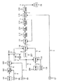
図1は本発明に係る一軸型複合サイクル発電プラントの第1実施形態を示す系統図である。
(First embodiment)
(Power plant configuration)
FIG. 1 is a system diagram showing a first embodiment of a single-shaft combined cycle power plant according to the present invention.
図1に示すように、本実施形態の一軸型複合サイクルプラントにおいて、ガスタービン1、圧縮機2、高圧蒸気タービン3a、低圧蒸気タービン3cおよび発電機4は、原動機部100を構成するとともに、それぞれの回転軸が同軸に配置されて結合されている。ガスタービン1には、燃焼器5で燃焼した燃焼ガスが供給され、この燃焼ガスにより駆動され、排気ガスを排出する。圧縮機2は、入口案内翼6を通して大気を吸い込んで高圧化し、その高圧空気を燃焼ガス生成用として燃焼器5に供給する。高圧蒸気タービン3aには、高圧主蒸気管16から高圧蒸気が供給される一方、低圧蒸気タービン3cには、低圧タービン蒸気供給系統としての低圧主蒸気管21から低圧蒸気が供給される。この低圧蒸気タービン3cは、ガスタービン1、高圧蒸気タービン3aとともに発電機4を駆動して電力を発生させる。この発電機4の出力軸の回転数は、回転数検出器38により検出される。
As shown in FIG. 1, in the single-shaft combined cycle plant of the present embodiment, the
排熱回収ボイラ7の排気ガス側入口端は、ガスタービン1の出口端に接続されており、排熱回収ボイラ7は、ガスタービン1からの排気ガスが供給されて蒸気を発生する。具体的に、排熱回収ボイラ7は、高圧蒸気を発生させる高圧ドラム13に接続された高圧過熱器10と、低圧蒸気を発生させる低圧ドラム15に接続された低圧過熱器12とを備えており、ここから発生した各蒸気を高圧蒸気タービン3a、低圧蒸気タービン3cのそれぞれに供給する構成になっている。なお、以下の説明では、高圧蒸気タービン3aおよび低圧蒸気タービン3cを総称する場合、蒸気タービン3という。また、低圧ドラム15で発生した低圧蒸気圧力は、検出器39により検出される。
An exhaust gas side inlet end of the exhaust heat recovery boiler 7 is connected to an outlet end of the
高圧主蒸気管16は、高圧蒸気圧力を検出する検出器57および高圧加減弁17を、低圧主蒸気管21は、低圧蒸気アイソレーション弁35、低圧蒸気圧力を検出する検出器56、低圧蒸気流量を検出する検出器40および低圧加減弁22を、それぞれ備えた管路構成になっている。高圧主蒸気管16は、検出器57の上流側で高圧タービンバイパス系81が分岐され、この高圧タービンバイパス系81に高圧タービンバイパス弁50が介装されている。同様に、低圧主蒸気管21は、検出器56の上流側で低圧タービンバイパス系83が分岐され、この低圧タービンバイパス系83に低圧タービンバイパス弁52が介装されている。これら高圧タービンバイパス系81および低圧タービンバイパス系83は、それぞれ復水器30に接続されている。
The high-pressure
低圧蒸気タービン3cの出口端は、復水器30および給水ポンプ28を介して排熱回収ボイラ7に接続されている。低圧蒸気タービン3cの低圧タービン排気圧力は、検出器55により検出される。復水器30には、循環水ポンプ29を駆動することにより循環水が供給される。この循環水は、高圧タービンバイパス系81および低圧タービンバイパス系83からそれぞれ供給された高圧蒸気および低圧蒸気を復水とする。
The outlet end of the low-
起動用ボイラ27は、補助蒸気供給管24に接続され、この補助蒸気供給管24に補助蒸気系60の一端が接続され、その他端が低圧主蒸気管21に接続されている。補助蒸気系60には、調節弁34および補助蒸気流量を検出する検出器41が介装されている。
The
制御装置70には、低圧蒸気圧力を検出する検出器56、低圧蒸気流量を検出する検出器40、および低圧タービン排気圧力を検出する検出器55のそれぞれの検出信号が入力される一方、制御装置70からは高圧加減弁17および低圧加減弁22の開度制御信号が出力される。
The
(発電プラントの作用)
次に、本実施形態の一軸型複合サイクル発電プラントの作用を説明する。
(Operation of power plant)
Next, the operation of the uniaxial combined cycle power plant of this embodiment will be described.
起動前、復水器30は、図示しない真空ポンプにより真空引きにされ、規定真空度に達すると、図示しないスターティングモータにより原動機部100を回転駆動させ、燃焼器5の着火によりガスタービン1および圧縮機2は併入運転に入る。
Before startup, the
また、プラントの起動前には、起動用ボイラ27を起動して立ち上げて補助蒸気を発生させ、この補助蒸気を補助蒸気供給管24を経て補助蒸気系60に供給し、調節弁34により流量が調節されて低圧主蒸気管21に供給される。
Before starting the plant, the start-up
すなわち、起動用ボイラ27は、蒸気が発生していない起動時において、補助蒸気を供給する目的で排熱回収ボイラ7とは別に設置されている。起動用ボイラ27で発生した補助蒸気は、上記のように補助蒸気供給管24、補助蒸気系60に介装された調節弁34を介して低圧主蒸気管21に供給され、さらに低圧加減弁22を介して蒸気タービン3に供給される。このように起動初期においては、排熱回収ボイラ7から発生する高圧蒸気や低圧蒸気の発生量が充分でないため、低圧タービン冷却蒸気として起動用ボイラ27からの補助蒸気が併用される。
That is, the
さらに、起動過程が進行すると、高圧蒸気および低圧蒸気の発生量が増加するため、低圧蒸気タービン冷却蒸気としてはこれらで充分となるので、経済運転のため起動用ボイラ27は停止され、補助蒸気の供給は打ち切られて高圧蒸気と低圧蒸気のみが低圧蒸気タービン3cに供給される。
Furthermore, since the generation amount of high-pressure steam and low-pressure steam increases as the start-up process proceeds, these are sufficient as low-pressure steam turbine cooling steam. Therefore, the start-up
圧縮機2は、入口案内翼6を通して大気を吸い込んで高圧化し、その高圧空気を燃焼ガス生成用として燃焼器5に供給している。この燃焼器5には、高圧空気とともに燃料が加えられ、高温の燃焼ガスを生成している。この高温の燃焼ガスがガスタービン1に供給され、ガスタービン1で膨張仕事をする。
The compressor 2 sucks the atmosphere through the inlet guide vanes 6 to increase the pressure, and supplies the high-pressure air to the combustor 5 for generating combustion gas. Fuel is added to the combustor 5 together with high-pressure air, and high-temperature combustion gas is generated. This high-temperature combustion gas is supplied to the
ガスタービン1から排出される排気ガスは、蒸気発生用の熱源として排熱回収ボイラ7に導入され、高圧過熱器10、低圧過熱器12および図示しない各圧力の蒸発器などを流通する給水や蒸気と熱交換した後、煙突を経て大気中に放散される。
Exhaust gas discharged from the
高圧ドラム13で発生した高圧蒸気は、高圧過熱器10で過熱された後、高圧主蒸気管16から高圧加減弁17を経て高圧蒸気タービン3aで仕事を行った後は、低圧加減弁22からの低圧蒸気と合流して低圧蒸気タービン3cに導入される。なお、本実施形態は、高圧蒸気タービン3aの途中段(排気部の近傍)において低圧蒸気が合流する。
The high-pressure steam generated in the high-
一方、低圧ドラム15で発生した低圧蒸気は、低圧過熱器12で過熱され、温度条件、圧力条件が適切になった時点で低圧蒸気アイソレーション弁35が開弁し、低圧主蒸気管21を通じて低圧加減弁22に導かれ、前述したように仕事をした高圧蒸気とともに低圧蒸気タービン3cに供給されることにより、ガスタービン1および高圧蒸気タービン3aとともに発電機4を駆動して電力を発生させる。
On the other hand, the low-pressure steam generated in the low-
ところで、上述したように発電機4の負荷遮断の発生後は、ガスタービン1を無負荷定格速度運転とし、電気系事故の復旧後は、迅速に再負荷上昇に備える運転が行われる。通常運転から無負荷定格速度運転に移行する過程では、無負荷運転のためガスタービン1への燃料の供給量が急速に少なくなり、蒸気タービン3では高圧加減弁17は全閉し、低圧加減弁22は過速防止のために一旦全閉後、低圧タービン冷却蒸気を確保するために開弁する。
By the way, as described above, after the load interruption of the generator 4 is generated, the
したがって、負荷遮断発生時には、高圧加減弁17が閉止されるため、高圧ドラム13で発生した高圧蒸気を、高圧タービンバイパス弁50を開弁することにより復水器30に逃がし、高圧蒸気圧力の上昇を防止している。同様に、低圧加減弁22が閉止されるため、低圧ドラム15で発生した低圧蒸気を、低圧タービンバイパス弁52を開弁することにより復水器30に逃がし、低圧蒸気圧力の上昇を防止している。
Therefore, when the load is interrupted, the high pressure control valve 17 is closed. Therefore, the high pressure steam generated in the
このように復水器30には、高圧蒸気および低圧蒸気が供給され、この水蒸気が循環水ポンプ29から供給される循環水により復水とされ、この復水が給水ポンプ28により排熱回収ボイラ7に供給される。
Thus, the
(制御装置の構成)
次に、図2を用いて本実施形態における低圧加減弁22の制御について説明する。図2は図1の低圧加減弁22の制御装置70を示すブロック図である。
(Configuration of control device)
Next, the control of the low
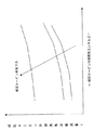
図2において、設定器101には、低圧蒸気タービン3cを冷却するために必要な蒸気エンタルピーが設定されている。関数発生器102は、設定器101からの低圧蒸気タービン3cを冷却するために必要な蒸気エンタルピー信号と、検出器55により検出された低圧タービン排気圧力信号aとにより、線形補間などで、必要な低圧タービン冷却蒸気流量信号bを求める。比較器103は、その低圧タービン冷却蒸気流量信号bと、検出器40により検出された低圧加減弁通過蒸気流量信号cとを比較する。
In FIG. 2, a steam enthalpy necessary for cooling the low-
AND回路104には、比較器103の出力信号の他に、一般的に他のロジックで計算される低圧加減弁ローディング許可指令信号d(低圧加減弁22の開弁許可指令)と、NOT回路105を介して出力される高圧加減弁ローディング信号e(高圧加減弁17が開弁している指標)とが入力される。
In addition to the output signal of the
設定器107には、予め低圧加減弁22の圧力設定値jを低下させる際の変化率(負の値)が設定されている。設定器108には、予め低圧加減弁22の圧力設定値jを上昇させる際の変化率(正の値)が設定され、負の変化率gとして出力する。設定器109には、予めゼロの値が設定されている。切替器110は、高圧加減弁ローディング信号eがオンの場合は、設定器108から負の変化率gを、オフの場合は設定器109からゼロの信号を、それぞれ出力する。
In the
切替器106では、AND回路104の出力がオンの場合は、設定器107から入力した負の変化率fを出力し、オフの場合は、切替器110から入力した負の変化率gまたはゼロを出力する。加算器111は、変化率制限器114の出力信号の値に切替器106からの信号iの値を加算する。
The
上限制限器112は、低圧ドラム15から低圧加減弁22までの蒸気配管の最大使用圧力、または蒸気配管上に設置される安全弁の設定値、または蒸気配管圧力に対する警報設定値などにより決定される低圧加減弁22の圧力設定値jに対する上限制限値が予め設定されており、加算器111からの信号の値と上記圧力設定値jとの比較を行う。
The
下限制限器113は、運用上または低圧ドラム15の機械的な特性・制約により決定される低圧加減弁22の圧力設定値jに対する下限制限値が予め設定されており、上限制限器112からの信号と上記圧力設定値jとの比較を行う。
The
変化率制限器114には、低圧加減弁22の圧力設定値jの変化率に対する、低圧ドラム15の圧力変化による水位への影響などの機械的な制約(変化率)が予め設定されており、下限制限器113からの信号に対して変化率制限を行う。
In the
減算器115では、変化率制限器114からの圧力設定値jと、検出器56にて検出された低圧蒸気圧力信号kの減算を行う。PID演算器116では、減算器115から得られた偏差信号lがゼロになるように低圧加減弁22に対して開度指令値mを出力する。
The
(制御装置の作用)
図2に示すように、設定器101には、低圧蒸気タービン3cを冷却するために必要な蒸気エンタルピーが設定されており、この蒸気エンタルピー信号と検出器55により検出された低圧タービン排気圧力信号aが関数発生器102に入力し、この関数発生器102にて現運転時に必要な低圧タービン冷却蒸気流量信号bを得る。
(Operation of control device)
As shown in FIG. 2, a steam enthalpy necessary for cooling the low-
具体的に、関数発生器102に設定される関数の一例を図3に示す。図3の横軸は、低圧蒸気タービン3cを冷却するために必要な低圧タービン冷却蒸気エンタルピーを示し、縦軸は低圧タービン冷却蒸気必要流量を示している。図3に示すように、低圧タービン冷却蒸気必要流量のカーブは、低圧タービン排気圧力条件により異なり、関数発生器102は、図2に示すように設定器101からの低圧蒸気タービン3cを冷却するために必要な蒸気エンタルピー信号と低圧タービン排気圧力信号aとから線形補間などにより、必要な低圧タービン冷却蒸気流量信号bを求める。
Specifically, an example of a function set in the
そして、低圧加減弁22を通過する低圧蒸気流量が検出器40により検出され、この低圧蒸気流量を低圧加減弁通過蒸気流量信号cとして比較器103に入力する。この比較器103では、低圧タービン冷却蒸気流量信号bと低圧加減弁通過蒸気流量信号cとの比較を行い、低圧加減弁通過蒸気流量信号cの値が低圧タービン冷却蒸気流量信号bの値より小さい場合に出力信号をオンさせ、AND回路104に出力する。
The low-pressure steam flow rate passing through the low-
このAND回路104には、その比較器103の出力信号の他に、一般的に他のロジックで計算される低圧加減弁ローディング許可指令信号d(低圧加減弁22の開弁許可指令)が入力されるとともに、高圧加減弁ローディング信号e(高圧加減弁17が開弁している指標)がNOT回路105を介して入力される。AND回路104では、比較器103の出力信号、低圧加減弁ローディング許可指令信号d、NOT回路105の出力信号のAND処理を行い、その出力を切替器106に出力する。
In addition to the output signal of the
設定器107には、予め低圧加減弁22の圧力設定値jを低下させる際の変化率(負の値)が設定されており、その出力を切替器106に負の変化率fとして出力する。
The
一方、設定器108には、予め低圧加減弁22の圧力設定値jを上昇させる際の変化率(正の値)が設定されており、負の変化率gとして、切替器110に出力される。設定器109には予めゼロの値が設定されており、切替器110に出力される。この切替器110では、高圧加減弁ローディング信号eがオンの場合は、設定器108から負の変化率gを、オフの場合は設定器109からゼロの信号を、それぞれ切替器106に出力する。
On the other hand, the
この切替器106では、AND回路104の出力がオンの場合は、設定器107からの負の変化率fを出力し、オフの場合は、切替器110から負の変化率gまたはゼロを加算器111に出力する。加算器111では、変化率制限器114の出力信号の値に切替器106からの信号iの値を加算し、上限制限器112に出力する。
The
この上限制限器112には、低圧ドラム15から低圧加減弁22までの蒸気配管の最大使用圧力、または蒸気配管上に設置される安全弁の設定値、または蒸気配管圧力に対する警報設定値などにより決定される低圧加減弁22の圧力設定値jに対する上限制限値が予め設定されており、加算器111からの信号の値と圧力設定値jとの比較を行い、値の小さい方を下限制限器113に出力する。この下限制限器113には、運用上または低圧ドラム15の機械的な特性・制約により決定される低圧加減弁22の圧力設定値jに対する下限制限値が予め設定されており、上限制限器112からの信号の値と圧力設定値jとの比較を行い、値の大きい方を変化率制限器114に出力する。この変化率制限器114には、低圧加減弁22の圧力設定値jの変化率に対する、低圧ドラム15の圧力変化による水位への影響などの機械的な制約(変化率)が予め設定されており、下限制限器113からの信号に対して変化率制限を行い、低圧加減弁22の圧力設定値jを得る。
The
次いで、低圧加減弁22の入口側の低圧蒸気圧力を検出器56にて検出し、低圧蒸気圧力信号kとして減算器115に入力する。この減算器115では、変化率制限器114から出力された圧力設定値jと低圧蒸気圧力信号kの値とで減算を行い、PID演算器116に偏差信号lを出力する。このPID演算器116では、偏差信号lがゼロになるように低圧加減弁22に対して開度指令値mを出力する。
Next, the low pressure steam pressure on the inlet side of the low
したがって、この制御装置70では、負荷遮断発生後の低圧加減弁22が開弁してよい条件であって、高圧加減弁17、高圧蒸気タービン3aを介して低圧蒸気タービン3cに十分な冷却蒸気が供給されていない条件下で、低圧加減弁22を通過する低圧蒸気流量が、必要とされる低圧タービン冷却蒸気流量より少ない場合は、低圧加減弁22の圧力設定値jを低下させて、低圧加減弁22の開度が大きくなるように制御する。
Therefore, in this
また、高圧加減弁17、高圧蒸気タービン3aを介して低圧蒸気タービン3cに十分な冷却蒸気が供給されている条件下では、低圧加減弁22の圧力設定値jを上昇させ、低圧加減弁22の開度が小さくなるように制御する。
Further, under the condition that sufficient cooling steam is supplied to the low
すなわち、本実施形態では、低圧加減弁22の圧力設定値jを低下させることにより、低圧ドラム15からの蒸気発生量を増加させ、低圧蒸気タービン3cの冷却蒸気量を確保するようにしている。
That is, in the present embodiment, the amount of steam generated from the low-
(第1実施形態の効果)
このように本実施形態によれば、負荷遮断後の低圧加減弁22の開弁時に、必要な低圧蒸気タービン冷却蒸気流量を確保するように低圧加減弁22の開度を制御することにより、低圧蒸気タービン3cの風損による過熱を未然に防止することが可能となる。
(Effect of 1st Embodiment)
As described above, according to the present embodiment, when the low-
(第2実施形態)
(制御装置の構成)
図4は本発明に係る一軸型複合サイクル発電プラントの第2実施形態を示す制御ブロック図である。なお、本実施形態の一軸型複合サイクル発電プラントの構成および作用は、図1に示す前記第1実施形態と同様であるため、その説明を省略する。また、図4に示す本実施形態の制御ブロック図において、図2に示す第1実施形態と同様な機能を有する構成要素には、同一の符号を付して説明を省略し、異なる構成および作用のみを説明する。
(Second Embodiment)
(Configuration of control device)
FIG. 4 is a control block diagram showing a second embodiment of the single-shaft combined cycle power plant according to the present invention. In addition, since the structure and effect | action of the single shaft type combined cycle power plant of this embodiment are the same as that of the said 1st Embodiment shown in FIG. 1, the description is abbreviate | omitted. Further, in the control block diagram of the present embodiment shown in FIG. 4, the same reference numerals are given to components having the same functions as those in the first embodiment shown in FIG. I will explain only.
図4に示すように、設定器207には、予め高圧タービンバイパス弁50の圧力設定値nを上昇させる際の変化率(正の値)が設定されている。一方、設定器208には、予め高圧タービンバイパス弁50の圧力設定値nを降下させる際の変化率(負の値)が設定されている。
As shown in FIG. 4, a rate of change (positive value) when the pressure set value n of the high-pressure
上限制限器212には、高圧ドラム13から高圧加減弁17までの蒸気配管の最大使用圧力、または蒸気配管上に設置される安全弁の設定値、または蒸気配管圧力に対する警報設定値などにより決定される高圧タービンバイパス弁50の圧力設定値に対する上限制限値が予め設定され、加算器111からの信号の値と圧力設定値nとの比較を行う。
The
下限制限器213には、運用上または高圧ドラム13の機械的な特性・制約により決定される高圧タービンバイパス弁50の圧力設定値nに対する下限制限値が予め設定され、上限制限器212からの信号の値と圧力設定値nとの比較を行う。
The
変化率制限器214には、高圧タービンバイパス弁50の設定値の変化率に対する、高圧ドラムなどの機械的な制約(変化率)が予め設定され、下限制限器213からの信号に対して変化率制限を行う。
In the
(制御装置の作用)
図4に示すように、制御装置70において、設定器207には、予め高圧タービンバイパス弁50の圧力設定値nを上昇させる際の変化率(正の値)が設定されており、その出力を切替器106に正の変化率gとして出力する。一方、設定器208には、予め高圧タービンバイパス弁50の圧力設定値nを降下させる際の変化率(負の値)が設定されており、負の変化率fとして、切替器110に出力される。
(Operation of control device)
As shown in FIG. 4, in the
また、上限制限器212には、高圧ドラム13から高圧加減弁17までの蒸気配管の最大使用圧力、または蒸気配管上に設置される安全弁の設定値、または蒸気配管圧力に対する警報設定値などにより決定される高圧タービンバイパス弁50の圧力設定値nに対する上限制限値が予め設定されており、加算器111からの信号の値と圧力設定値nとの比較を行い、値の小さい方を下限制限器213に出力する。この下限制限器213には、運用上または高圧ドラム13の機械的な特性・制約により決定される高圧タービンバイパス弁50の圧力設定値nに対する下限制限値が予め設定されており、上限制限器212からの信号の値と圧力設定値nとの比較を行い、値の大きい方を変化率制限器214に出力する。
The
この変化率制限器214には、高圧タービンバイパス弁50の圧力設定値nの変化率に対する、高圧ドラム13の圧力変化による水位への影響などの機械的な制約(変化率)が予め設定されており、下限制限器213からの信号に対して変化率制限を行い、高圧タービンバイパス弁50の圧力設定値nを得る。
This rate-of-
次いで、高圧加減弁17の入口側の低圧蒸気圧力を検出器57にて検出し、高圧蒸気圧力信号oとして減算器115に入力する。この減算器115では、変化率制限器214から出力された圧力設定値nと高圧蒸気圧力信号oの値とで減算を行い、PID演算器116に偏差信号lを出力する。このPID演算器116では、偏差信号lがゼロになるように高圧タービンバイパス弁50に対して開度指令値pを出力する。
Next, the low pressure steam pressure on the inlet side of the high pressure control valve 17 is detected by the
したがって、この制御装置70では、負荷遮断発生後の低圧加減弁22が開弁してよい条件であって、高圧加減弁17、高圧蒸気タービン3aを介して低圧蒸気タービン3cに十分な冷却蒸気が供給されていない条件下で、低圧加減弁22を通過する低圧蒸気流量が、必要とされる低圧タービン冷却蒸気流量より少ない場合は、高圧タービンバイパス弁50の圧力設定値nを上昇させて、高圧タービンバイパス弁50の開度が小さくなるように制御する。また、高圧加減弁17、高圧蒸気タービン3aを介して低圧蒸気タービン3cに十分な冷却蒸気が供給されている条件下では、高圧タービンバイパス弁50の圧力設定値nを降下させ、高圧タービンバイパス弁50の開度が大きくなるように制御する。
Therefore, in this
すなわち、本実施形態のように二圧式の排熱回収ボイラ7の場合は、高圧タービンバイパス弁50の圧力設定値nを上昇させ、排熱回収ボイラ7内における集熱バランスを高圧系から低圧系に移行させ、高圧系での熱交換量を低下させ、低圧系での熱交換量を増加させることにより、低圧ドラム15からの蒸気量を増加させ、低圧蒸気タービン3cに供給される必要な冷却蒸気量を確保するようにしている。
That is, in the case of the two-pressure type exhaust heat recovery boiler 7 as in the present embodiment, the pressure set value n of the high pressure
(第2実施形態の効果)
このように本実施形態によれば、低圧タービン冷却蒸気流量が足りない場合に、高圧タービンバイパス弁50の圧力設定値nを上昇させることにより、高圧ドラム13からの発生蒸気量を低下させ、すなわち高圧蒸気系での排熱回収ボイラ7内でのガスタービン1の排気ガスとの熱交換量を低下させる。その結果として、低圧蒸気系での熱交換量を増加させることになり、低圧ドラム15から発生する蒸気量を増加させることが可能となり、低圧蒸気タービン3cに供給される必要な冷却蒸気量を確保することができ、低圧蒸気タービン3cの風損による過熱を未然に防止することが可能となる。
(Effect of 2nd Embodiment)
Thus, according to this embodiment, when the low-pressure turbine cooling steam flow rate is insufficient, the amount of steam generated from the high-
(第3実施形態)
(発電プラントの構成)
図5は本発明に係る一軸型複合サイクル発電プラントの第3実施形態を示す系統図である。図6は図5の中圧タービンバイパス弁51の制御装置71を示すブロック図である。なお、図5および図6において、図1および図2に示す第1実施形態と同一の構成要素には、それぞれ同一の符号を付して説明を省略し、異なる構成および作用のみを説明する。
(Third embodiment)
(Power plant configuration)
FIG. 5 is a system diagram showing a third embodiment of the single-shaft combined cycle power plant according to the present invention. FIG. 6 is a block diagram showing a
前記第1実施形態が高圧および低圧の二圧の蒸気システムで構成する一軸型複合サイクル発電プラントであるのに対し、図5に示す本実施形態は、高圧、中圧および低圧の三圧の蒸気システムで構成する一軸型複合サイクル発電プラントである。 While the first embodiment is a single-shaft combined cycle power plant configured with a high-pressure and low-pressure two-pressure steam system, this embodiment shown in FIG. 5 is a high-pressure, medium-pressure, and low-pressure three-pressure steam. This is a single-shaft combined cycle power plant configured by the system.
図5に示すように、本実施形態の一軸型複合サイクル発電プラントにおいて、排熱回収ボイラ7は、高圧蒸気よりも低くかつ低圧蒸気よりも高い圧力の中圧蒸気を発生させる中圧ドラム14と、この中圧ドラム14に接続された中圧過熱器11と、高温再熱蒸気を発生させる再熱器9をさらに備える。
As shown in FIG. 5, in the uniaxial combined cycle power plant of this embodiment, the exhaust heat recovery boiler 7 includes an
また、本実施形態は、高圧蒸気タービン3aからの排気蒸気を中圧蒸気と合流させて再熱器9に供給する低温再熱系統18と、高圧蒸気タービン3aおよび低圧蒸気タービン3cと同軸に配置され、かつ再熱器9から高温再熱蒸気管61を経て供給される高温再熱蒸気により駆動される中圧蒸気タービン3bをさらに備える。そして、高温再熱蒸気管61には、再熱加減弁20と、この再熱加減弁20の入口側の低圧蒸気圧力を検出する検出器58が介装されている。
Moreover, this embodiment arrange | positions coaxially with the low
高温再熱蒸気管61は、検出器58の上流側で中圧タービンバイパス系82が分岐され、この中圧タービンバイパス系82に中圧タービンバイパス弁51が介装されている。中圧タービンバイパス系82は、前述した高圧タービンバイパス系81および低圧タービンバイパス系83と同様に復水器30に接続されている。
In the high temperature reheat steam pipe 61, an intermediate pressure
さらに、低圧タービン蒸気供給系統62は、中圧蒸気タービン3b内で仕事をして減圧された高温再熱蒸気と低圧蒸気とを合流させて低圧蒸気タービン3cの低圧タービン蒸気とするよう構成されている。
Further, the low-pressure turbine
制御装置71には、低圧蒸気流量を検出する検出器40、低圧タービン排気圧力を検出する検出器55および再熱加減弁20の入口側の低圧蒸気圧力を検出する検出器58のそれぞれの検出信号が入力される一方、制御装置71からは、高圧加減弁17、再熱加減弁20および中圧タービンバイパス弁51の開度制御信号が出力される。
The
したがって、負荷遮断発生時には、高圧加減弁17および再熱加減弁20が閉止されるため、中圧ドラム14で発生した中圧蒸気を、中圧タービンバイパス弁51を開弁することにより中圧タービンバイパス系82を経て復水器30に逃がす。そして、制御装置71は、中圧タービンバイパス弁51の圧力設定値が上昇するように開度を制御することにより、低圧蒸気の発生流量が増加するようにしている。
Therefore, when the load is interrupted, the high pressure control valve 17 and the
(制御装置の構成)
図6に示すように、制御装置71において、設定器307には、予め中圧タービンバイパス弁51の設定値qを上昇させる際の変化率(正の値)が設定されている。一方、設定器308には、予め中圧タービンバイパス弁50の設定値qを降下させる際の変化率(負の値)が設定されており、負の変化率fとして切替器110に出力する。
(Configuration of control device)
As shown in FIG. 6, in the
上限制限器312には、中圧ドラム14から低温再熱系統18までの蒸気配管の最大使用圧力、または蒸気配管上に設置される図示しない安全弁の設定値、または蒸気配管圧力に対する警報設定値などにより決定される中圧タービンバイパス弁51の設定値に対する上限制限値が予め設定されている。
The
下限制限器313には、運用上または中圧ドラム14の機械的な特性・制約により決定される中圧タービンバイパス弁51の設定値に対する下限制限値が予め設定されている。変化率制限器314には、高圧タービンバイパス弁50の設定値の変化率に対する、中圧ドラム14などの機械的な制約(変化率)が予め設定されており、下限制限器313からの信号に対して変化率制限を行う。
The
(制御装置の作用)
図6に示すように、制御装置71において、設定器307には、予め中圧タービンバイパス弁51の圧力設定値qを上昇させる際の変化率(正の値)が設定されており、その出力を切替器106に正の変化率gとして出力する。一方、設定器308には、予め中圧タービンバイパス弁50の圧力設定値qを降下させる際の変化率(負の値)が設定されており、負の変化率fとして、切替器110に出力される。
(Operation of control device)
As shown in FIG. 6, in the
また、上限制限器312には、中圧ドラム14から低温再熱系統18までの蒸気配管の最大使用圧力、または蒸気配管上に設置される図示しない安全弁の設定値、または蒸気配管圧力に対する警報設定値などにより決定される中圧タービンバイパス弁51の圧力設定値qに対する上限制限値が予め設定されており、加算器111からの信号の値と圧力設定値qとの比較を行い、値の小さい方を下限制限器313に出力する。この下限制限器313には、運用上または中圧ドラム14の機械的な特性・制約により決定される中圧タービンバイパス弁51の圧力設定値qに対する下限制限値が予め設定されており、上限制限器312からの信号の値と圧力設定値nとの比較を行い、値の大きい方を変化率制限器314に出力する。
The
この変化率制限器314には、高圧タービンバイパス弁50の圧力設定値qの変化率に対する、中圧ドラム14の圧力変化による水位への影響などの機械的な制約(変化率)が予め設定されており、下限制限器313からの信号に対して変化率制限を行い、中圧タービンバイパス弁51の圧力設定値qを得る。
This rate-of-
次いで、再熱加減弁20の入口側の低圧蒸気圧力を検出器58にて検出し、中圧蒸気圧力信号rとして減算器115に入力する。この減算器115では、変化率制限器314から出力された圧力設定値qと中圧蒸気圧力信号rの値とで減算を行い、PID演算器116に偏差信号lを出力する。このPID演算器116では、偏差信号lがゼロになるように中圧タービンバイパス弁51に対して開度指令値sを出力する。
Next, the low pressure steam pressure on the inlet side of the
したがって、この制御装置71では、負荷遮断発生後の低圧加減弁22が開弁してよい条件であって、高圧加減弁17、高圧蒸気タービン3aを介して低圧蒸気タービン3cに十分な冷却蒸気が供給されていない条件下で、低圧加減弁22を通過する低圧蒸気流量が、必要とされる低圧タービン冷却蒸気流量より少ない場合は、中圧タービンバイパス弁51の圧力設定値qを上昇させて、中圧タービンバイパス弁51の開度が小さくなるように制御する。
Therefore, in this
また、高圧加減弁17、高圧蒸気タービン3aを介して低圧蒸気タービン3cに十分な冷却蒸気が供給されている条件下では、中圧タービンバイパス弁51の圧力設定値qを降下させ、中圧タービンバイパス弁51の開度が大きくなるように制御する。
Further, under the condition that sufficient cooling steam is supplied to the low-
すなわち、本実施形態のように三圧式の排熱回収ボイラ7の場合は、中圧タービンバイパス弁51の圧力設定値qを上昇させ、排熱回収ボイラ7内における集熱バランスを中圧蒸気系から低圧蒸気系に移行させ、中圧蒸気系での熱交換量を低下させ、低圧蒸気系での熱交換量を増加させることにより、低圧ドラム15からの蒸気量を増加させ、低圧蒸気タービン3cに供給される冷却蒸気量を確保するようにしている。
That is, in the case of the three-pressure type exhaust heat recovery boiler 7 as in the present embodiment, the pressure set value q of the intermediate pressure
(第3実施形態の効果)
このように本実施形態によれば、低圧タービン冷却蒸気流量が足りない場合に、中圧タービンバイパス弁51の圧力設定値qを上昇させることにより、中圧ドラム14からの発生蒸気量を低下させ、すなわち中圧蒸気系での排熱回収ボイラ7内でのガスタービン1の排気ガスとの熱交換量を低下させる。その結果として、低圧蒸気系での熱交換量を増加させることになり、低圧ドラム15から発生する蒸気量を増加させることが可能となり、低圧蒸気タービン3cに供給される必要な冷却蒸気量を確保することができ、低圧蒸気タービン3cの風損による過熱を未然に防止することが可能となる。
(Effect of the third embodiment)
Thus, according to the present embodiment, when the low-pressure turbine cooling steam flow rate is insufficient, the amount of steam generated from the intermediate-
(第4実施形態)
図7は本発明に係る一軸型複合サイクル発電プラントの第4実施形態を示す系統図である。なお、第4実施形態は、図5および図6に示す前記第3実施形態の変更例であって、図7において図5と同一の構成要素には、同一の符号を付して説明を省略し、異なる構成および作用のみを説明する。
(Fourth embodiment)
FIG. 7 is a system diagram showing a fourth embodiment of the single-shaft combined cycle power plant according to the present invention. The fourth embodiment is a modification of the third embodiment shown in FIGS. 5 and 6. In FIG. 7, the same components as those in FIG. Only the different configurations and operations will be described.
図5に示す一軸型複合サイクル発電プラントでは、ガスタービン1はその高温部の冷却媒体として空気を使用する空気冷却方式であるのに対し、本実施形態の一軸型複合サイクル発電プラントのガスタービン1は、その高温部の冷却媒体として蒸気を使用した蒸気冷却方式を採用している。
In the single-shaft combined cycle power plant shown in FIG. 5, the
図7に示すように、本実施形態の一軸型複合サイクル発電プラントにおいて、低温再熱系統18と再熱器9との間には、ガスタービン1の高温部を冷却するための冷却蒸気系統45が介装されている。この冷却蒸気系統45の蒸気は、図示しない蒸気往路配管によりガスタービン1に導かれ、その高温部を冷却した後、図示しない蒸気帰路配管に導かれて冷却蒸気系統45に戻るように構成されている。
As shown in FIG. 7, in the single-shaft combined cycle power plant of this embodiment, a cooling
ガスタービン1の高温部を冷却した蒸気は、配管46および逆止弁47を介して低温再熱系統18に導入される。
The steam that has cooled the high-temperature portion of the
このように本実施形態によれば、低温再熱系統18と再熱器9との間にガスタービン1の高温部を冷却するための冷却蒸気系統45を介装したことにより、その高温部の冷却媒体として蒸気を使用したにもかかわらず、前記第3実施形態と同様の効果が得られる。
Thus, according to the present embodiment, the cooling
1…ガスタービン、2…圧縮機、3…蒸気タービン、3a…高圧蒸気タービン、3b…中圧蒸気タービン、3c…低圧蒸気タービン、4…発電機、5…燃焼器、6…入口案内翼、7…排熱回収ボイラ、9…再熱器、10…高圧過熱器、11…中圧過熱器、12…低圧過熱器、13…高圧ドラム、14…中圧ドラム、15…低圧ドラム、16…高圧主蒸気管、17…高圧加減弁、18…低温再熱系統、20…再熱加減弁、21…低圧主蒸気管、22…低圧加減弁、24…補助蒸気供給管、27…起動用ボイラ、28…給水ポンプ、29…循環水ポンプ、30…復水器、34…調節弁、35…低圧蒸気アイソレーション弁、38…回転数検出器、39…検出器、40…検出器、41…検出器、45…冷却蒸気系統、46…配管、47…逆止弁、50…高圧タービンバイパス弁、51…中圧タービンバイパス弁、52…低圧タービンバイパス弁、55…検出器、56…検出器、57…検出器、58…検出器、61…高温再熱蒸気管、62…低圧タービン蒸気供給系統、70…制御装置、71…制御装置、81…高圧タービンバイパス系、82…中圧タービンバイパス系、83…低圧タービンバイパス、100…原動機部、101…設定器、102…関数発生器、103…比較器、104…AND回路、105…NOT回路、106…切替器、107…設定器、108…設定器、109…設定器、110…切替器、111…加算器、112…上限制限器、113…下限制限器、114…変化率制限器、115…減算器、116…PID演算器、207…設定器、208…設定器、212…上限制限器、213…下限制限器、214…変化率制限器、307…設定器、308…設定器、312…上限制限器、313…下限制限器、314…変化率制限器。
DESCRIPTION OF
Claims (6)
前記高圧ドラムより低い圧力の低圧蒸気を発生させる低圧ドラムからの前記低圧蒸気が低圧加減弁を介して供給され、この低圧蒸気と前記高圧蒸気タービン内で仕事をした前記高圧蒸気とを合流させた蒸気を低圧タービン蒸気として供給する低圧タービン蒸気供給系統と、
前記ガスタービンおよび前記高圧蒸気タービンと同軸に配置して結合され、前記低圧タービン蒸気により駆動される低圧蒸気タービンと、
前記ガスタービンと同軸に配置して結合された発電機の負荷遮断後の無負荷定格速度運転を含む前記ガスタービンの極低燃料運転時に、前記高圧加減弁を全閉する制御を行うとともに、前記低圧加減弁の圧力設定値を低下させるように制御する制御手段と、
を備えることを特徴とする一軸型複合サイクル発電プラント。 A high-pressure steam turbine that is arranged coaxially with the gas turbine and is driven by being supplied with high-pressure steam from a high-pressure drum of an exhaust heat recovery boiler via a high-pressure control valve;
The low-pressure steam from the low-pressure drum that generates low-pressure steam having a pressure lower than that of the high-pressure drum is supplied via a low-pressure control valve, and the low-pressure steam and the high-pressure steam that has worked in the high-pressure steam turbine are merged. A low pressure turbine steam supply system for supplying steam as low pressure turbine steam;
A low-pressure steam turbine disposed coaxially and coupled to the gas turbine and the high-pressure steam turbine and driven by the low-pressure turbine steam;
During the extremely low fuel operation of the gas turbine, including no-load rated speed operation after load interruption of the generator that is arranged coaxially with the gas turbine, the high pressure regulator is controlled to be fully closed, and Control means for controlling the pressure setting value of the low pressure regulating valve to be lowered;
A single-shaft combined cycle power plant comprising:
前記高圧ドラムより低い圧力の低圧蒸気を発生させる低圧ドラムからの前記低圧蒸気が低圧加減弁を介して供給され、この低圧蒸気と前記高圧蒸気タービン内で仕事をした前記高圧蒸気とを合流させた蒸気を低圧タービン蒸気として供給する低圧タービン蒸気供給系統と、
前記ガスタービンおよび前記高圧蒸気タービンと同軸に配置して結合され、前記低圧タービン蒸気により駆動される低圧蒸気タービンと、
前記高圧蒸気をバイパスし、高圧タービンバイパス弁が介装された高圧バイパス系統と、
前記ガスタービンと同軸に配置して結合された発電機の負荷遮断後の無負荷定格速度運転を含む前記ガスタービンの極低燃料運転時に、前記高圧加減弁を全閉する制御を行うとともに、前記高圧タービンバイパス弁の圧力設定値を上昇させるように制御する制御手段と、
を備えることを特徴とする一軸型複合サイクル発電プラント。 A high-pressure steam turbine that is arranged coaxially with the gas turbine and is driven by being supplied with high-pressure steam from a high-pressure drum of an exhaust heat recovery boiler via a high-pressure control valve;
The low-pressure steam from the low-pressure drum that generates low-pressure steam having a pressure lower than that of the high-pressure drum is supplied via a low-pressure control valve, and the low-pressure steam and the high-pressure steam that has worked in the high-pressure steam turbine are merged. A low pressure turbine steam supply system for supplying steam as low pressure turbine steam;
A low-pressure steam turbine disposed coaxially and coupled to the gas turbine and the high-pressure steam turbine and driven by the low-pressure turbine steam;
A high-pressure bypass system bypassing the high-pressure steam and interposing a high-pressure turbine bypass valve;
During the extremely low fuel operation of the gas turbine, including no-load rated speed operation after load interruption of the generator that is arranged coaxially with the gas turbine, the high pressure regulator is controlled to be fully closed, and Control means for controlling the pressure setting value of the high-pressure turbine bypass valve to increase;
A single-shaft combined cycle power plant comprising:
前記ガスタービンおよび前記高圧蒸気タービンと同軸に配置して結合され、低圧蒸気により駆動される低圧蒸気タービンと、
前記高圧蒸気をバイパスし、高圧タービンバイパス弁が介装された高圧バイパス系統と、
前記高圧蒸気よりも低くかつ低圧蒸気よりも高い圧力の中圧蒸気を発生させる中圧ドラムからの中圧蒸気を前記高圧蒸気タービンからの排気蒸気と合流させ、高温再熱蒸気を発生させる再熱器に供給する低温再熱系統と、
前記高圧蒸気タービンおよび前記低圧蒸気タービンと同軸に配置され、前記再熱器からの高温再熱蒸気が中圧調節弁を経由して供給されて駆動する中圧蒸気タービンと、
前記中圧蒸気タービン内で仕事をして減圧された前記高温再熱蒸気と前記低圧蒸気とを合流させて前記低圧蒸気タービンを駆動する低圧タービン蒸気供給系統と、
前記中圧蒸気をバイパスし、中圧タービンバイパス弁が介装された中圧バイパス系統と、
前記ガスタービンと同軸に配置して結合された発電機の負荷遮断後の無負荷定格速度運転を含む前記ガスタービンの極低燃料運転時に、前記高圧加減弁および前記中圧調節弁を全閉する制御を行うとともに、前記中圧タービンバイパス弁の圧力設定値を上昇させるように制御する制御手段と、
を備えることを特徴とする一軸型複合サイクル発電プラント。 A high-pressure steam turbine that is arranged coaxially with the gas turbine and is driven by being supplied with high-pressure steam from a high-pressure drum of an exhaust heat recovery boiler via a high-pressure control valve;
A low-pressure steam turbine that is coaxially disposed and coupled to the gas turbine and the high-pressure steam turbine and is driven by low-pressure steam;
A high-pressure bypass system bypassing the high-pressure steam and interposing a high-pressure turbine bypass valve;
Reheating to generate high-temperature reheat steam by combining medium-pressure steam from an intermediate-pressure drum that generates intermediate-pressure steam at a pressure lower than that of the high-pressure steam and higher than that of low-pressure steam with exhaust steam from the high-pressure steam turbine. A low-temperature reheat system to supply
An intermediate pressure steam turbine that is arranged coaxially with the high pressure steam turbine and the low pressure steam turbine and is driven by being supplied with high temperature reheat steam from the reheater via an intermediate pressure control valve;
A low-pressure turbine steam supply system for driving the low-pressure steam turbine by joining the high-temperature reheat steam and the low-pressure steam, which are decompressed by working in the intermediate-pressure steam turbine;
An intermediate pressure bypass system that bypasses the intermediate pressure steam and is provided with an intermediate pressure turbine bypass valve;
The high pressure regulating valve and the intermediate pressure control valve are fully closed during extremely low fuel operation of the gas turbine, including no-load rated speed operation after load interruption of a generator arranged coaxially with the gas turbine. Control means for performing control and controlling so as to increase the pressure set value of the intermediate pressure turbine bypass valve;
A single-shaft combined cycle power plant comprising:
前記発電機の負荷遮断後の無負荷定格速度運転を含む前記ガスタービンの極低燃料運転時に、前記高圧加減弁を全閉する制御を行う全閉制御ステップと、
前記低圧加減弁の圧力設定値を低下させるように制御する圧力設定値制御ステップと、
を有することを特徴とする一軸型複合サイクル発電プラントの運転方法。 A gas turbine, a high-pressure steam turbine, a low-pressure steam turbine, and a generator are coaxially arranged and connected, and combustion gas is sent to the gas turbine to drive it, and the exhaust gas of the combustion gas is used as a heat source for high pressure in the exhaust heat recovery boiler. Generating low-pressure steam having a pressure lower than that of the high-pressure steam, supplying the high-pressure steam via a high-pressure control valve to work on the high-pressure steam turbine, and generating the low-pressure steam via the low-pressure control valve. In the operation method of the single-shaft combined cycle power plant in which the low-pressure steam turbine supplies the work and supplies the work,
A fully-closed control step for performing control to fully close the high-pressure control valve during extremely low fuel operation of the gas turbine including no-load rated speed operation after load interruption of the generator;
A pressure set value control step for controlling the pressure set value of the low pressure adjusting valve to decrease;
A method for operating a single-shaft combined cycle power plant, comprising:
前記発電機の負荷遮断後の無負荷定格速度運転を含む前記ガスタービンの極低燃料運転時に、前記高圧加減弁を全閉する制御を行う全閉制御ステップと、
前記高圧蒸気をバイパスする高圧バイパス系統に介装された高圧タービンバイパス弁の圧力設定値を上昇させるように制御する圧力設定値制御ステップと、
を有することを特徴とする一軸型複合サイクル発電プラントの運転方法。 A gas turbine, a high-pressure steam turbine, a low-pressure steam turbine, and a generator are coaxially arranged and connected, and combustion gas is sent to the gas turbine to drive it, and the exhaust gas of the combustion gas is used as a heat source for high pressure in the exhaust heat recovery boiler. Generating low-pressure steam having a pressure lower than that of the high-pressure steam, supplying the high-pressure steam via a high-pressure control valve to work on the high-pressure steam turbine, and generating the low-pressure steam via the low-pressure control valve. In the operation method of the single-shaft combined cycle power plant in which the low-pressure steam turbine supplies the work and supplies the work,
A fully-closed control step for performing control to fully close the high-pressure control valve during extremely low fuel operation of the gas turbine including no-load rated speed operation after load interruption of the generator;
A pressure set value control step for controlling the pressure set value of the high pressure turbine bypass valve interposed in the high pressure bypass system to bypass the high pressure steam; and
A method for operating a single-shaft combined cycle power plant, comprising:
前記発電機の負荷遮断後の無負荷定格速度運転を含む前記ガスタービンの極低燃料運転時に、前記高圧加減弁および前記中圧調節弁を全閉する制御を行う全閉制御ステップと、
前記中圧蒸気をバイパスする中圧バイパス系統に介装された中圧タービンバイパス弁の圧力設定値を上昇させるように制御する圧力設定値制御ステップと、
を有することを特徴とする一軸型複合サイクル発電プラントの運転方法。 A gas turbine, a high-pressure steam turbine, an intermediate-pressure steam turbine, a low-pressure steam turbine, and a generator are arranged coaxially and connected to each other, and a combustion gas is sent to the gas turbine for driving, and the exhaust gas of the combustion gas is used as a heat source to exhaust heat. The recovery boiler generates high-pressure steam, and generates low-pressure steam having a pressure lower than that of the high-pressure steam and low-pressure steam having a pressure lower than that of the high-pressure steam, and the intermediate-pressure steam is discharged from the high-pressure steam turbine. The high-temperature reheat steam and the low-pressure steam, which are supplied to a reheater that generates high-temperature reheat steam and is reduced in pressure by working in the intermediate-pressure steam turbine via an intermediate pressure control valve. In a method for operating a single-shaft combined cycle power plant in which the low-pressure steam turbines are combined to perform work,
A fully-closed control step for performing control to fully close the high-pressure control valve and the intermediate pressure control valve during extremely low fuel operation of the gas turbine including no-load rated speed operation after load interruption of the generator;
A pressure setting value control step for controlling the pressure setting value of the intermediate pressure turbine bypass valve interposed in the intermediate pressure bypass system for bypassing the intermediate pressure steam; and
A method for operating a single-shaft combined cycle power plant, comprising:
Priority Applications (1)
| Application Number | Priority Date | Filing Date | Title |
|---|---|---|---|
| JP2011027487A JP2012167571A (en) | 2011-02-10 | 2011-02-10 | Uniaxial combined cycle power generation plant, and method of operating the same |
Applications Claiming Priority (1)
| Application Number | Priority Date | Filing Date | Title |
|---|---|---|---|
| JP2011027487A JP2012167571A (en) | 2011-02-10 | 2011-02-10 | Uniaxial combined cycle power generation plant, and method of operating the same |
Publications (1)
| Publication Number | Publication Date |
|---|---|
| JP2012167571A true JP2012167571A (en) | 2012-09-06 |
Family
ID=46971955
Family Applications (1)
| Application Number | Title | Priority Date | Filing Date |
|---|---|---|---|
| JP2011027487A Withdrawn JP2012167571A (en) | 2011-02-10 | 2011-02-10 | Uniaxial combined cycle power generation plant, and method of operating the same |
Country Status (1)
| Country | Link |
|---|---|
| JP (1) | JP2012167571A (en) |
Cited By (10)
| Publication number | Priority date | Publication date | Assignee | Title |
|---|---|---|---|---|
| JP2014084847A (en) * | 2012-10-26 | 2014-05-12 | Mitsubishi Heavy Ind Ltd | Combined cycle plant, its stopping method, and its control method |
| CN104033249A (en) * | 2013-03-06 | 2014-09-10 | 阿尔斯通技术有限公司 | Method for operating combined-cycle power plant |
| JP2015021407A (en) * | 2013-07-17 | 2015-02-02 | 株式会社東芝 | Control valve controlling method, control valve controlling device and power-generating plant using these method and device |
| CN104632302A (en) * | 2015-01-05 | 2015-05-20 | 广东电网有限责任公司电力科学研究院 | Condensing steam turbine sliding pressure operation curve testing/implementation method |
| JP2015190384A (en) * | 2014-03-28 | 2015-11-02 | 三菱日立パワーシステムズ株式会社 | Turbine output estimation method of uniaxial type combined cycle plant |
| JP2017096165A (en) * | 2015-11-24 | 2017-06-01 | 株式会社東芝 | Control device and control method of adjustment value |
| JP2017133377A (en) * | 2016-01-25 | 2017-08-03 | 株式会社東芝 | Plant control device and plant control method |
| CN107152319A (en) * | 2017-06-23 | 2017-09-12 | 山东中实易通集团有限公司 | A kind of adjacent machine steam of supercritical unit mutually helps system and method |
| CN107152317A (en) * | 2017-07-14 | 2017-09-12 | 上海电气电站设备有限公司 | Combination circulation steam turbine quickly starts warming-up system and method |
| CN112412549A (en) * | 2020-11-17 | 2021-02-26 | 广西电网有限责任公司电力科学研究院 | Two-stage bypass control system of steam turbine |
-
2011
- 2011-02-10 JP JP2011027487A patent/JP2012167571A/en not_active Withdrawn
Cited By (14)
| Publication number | Priority date | Publication date | Assignee | Title |
|---|---|---|---|---|
| JP2014084847A (en) * | 2012-10-26 | 2014-05-12 | Mitsubishi Heavy Ind Ltd | Combined cycle plant, its stopping method, and its control method |
| US9631521B2 (en) | 2013-03-06 | 2017-04-25 | General Electric Technology Gmbh | Method for operating a combined-cycle power plant |
| CN104033249A (en) * | 2013-03-06 | 2014-09-10 | 阿尔斯通技术有限公司 | Method for operating combined-cycle power plant |
| JP2015021407A (en) * | 2013-07-17 | 2015-02-02 | 株式会社東芝 | Control valve controlling method, control valve controlling device and power-generating plant using these method and device |
| JP2015190384A (en) * | 2014-03-28 | 2015-11-02 | 三菱日立パワーシステムズ株式会社 | Turbine output estimation method of uniaxial type combined cycle plant |
| CN104632302A (en) * | 2015-01-05 | 2015-05-20 | 广东电网有限责任公司电力科学研究院 | Condensing steam turbine sliding pressure operation curve testing/implementation method |
| CN104632302B (en) * | 2015-01-05 | 2016-01-20 | 广东电网有限责任公司电力科学研究院 | A kind of condensing steam turbine sliding pressure operation curve test/implementation methods |
| JP2017096165A (en) * | 2015-11-24 | 2017-06-01 | 株式会社東芝 | Control device and control method of adjustment value |
| JP2017133377A (en) * | 2016-01-25 | 2017-08-03 | 株式会社東芝 | Plant control device and plant control method |
| CN107152319A (en) * | 2017-06-23 | 2017-09-12 | 山东中实易通集团有限公司 | A kind of adjacent machine steam of supercritical unit mutually helps system and method |
| CN107152319B (en) * | 2017-06-23 | 2023-06-02 | 山东中实易通集团有限公司 | Supercritical unit neighbor steam mutual aid system and method thereof |
| CN107152317A (en) * | 2017-07-14 | 2017-09-12 | 上海电气电站设备有限公司 | Combination circulation steam turbine quickly starts warming-up system and method |
| CN107152317B (en) * | 2017-07-14 | 2023-06-23 | 上海电气电站设备有限公司 | Rapid starting and warming-up system and method for combined cycle steam turbine |
| CN112412549A (en) * | 2020-11-17 | 2021-02-26 | 广西电网有限责任公司电力科学研究院 | Two-stage bypass control system of steam turbine |
Similar Documents
| Publication | Publication Date | Title |
|---|---|---|
| JP2012167571A (en) | Uniaxial combined cycle power generation plant, and method of operating the same | |
| EP2423462B1 (en) | Single shaft combined cycle power plant start-up method and single shaft combined cycle power plant | |
| US10655543B2 (en) | Gas turbine, combined cycle plant, and activation method of gas turbine | |
| EP2333255B1 (en) | Fossil fuel combustion thermal power system including carbon dioxide separation and capture unit | |
| JP3800384B2 (en) | Combined power generation equipment | |
| JPH1193694A (en) | Gas turbine plant | |
| US20120183413A1 (en) | Reactor Feedwater Pump Control System | |
| WO2015141458A1 (en) | Combined cycle plant, method for controlling same, and device for controlling same | |
| JPH09112215A (en) | Gas turbine power plant and method of operating thereof | |
| JP4503995B2 (en) | Reheat steam turbine plant and operation method thereof | |
| JP5694112B2 (en) | Uniaxial combined cycle power plant and operation method thereof | |
| JP6071421B2 (en) | Combined cycle plant, method for stopping the same, and control device therefor | |
| JPH0693879A (en) | Combined plant and operation thereof | |
| JP3919966B2 (en) | Operation method of combined cycle power plant | |
| JP4373420B2 (en) | Combined power plant and closed air cooled gas turbine system | |
| JP2000130108A (en) | Starting method for combined cycle power plant | |
| JP2010196473A (en) | Electric power plant water supply device, and method for controlling the same | |
| JP3750519B2 (en) | Combined plant and operation method thereof | |
| JP5812873B2 (en) | Combined cycle power plant | |
| JP3518252B2 (en) | Closed steam cooled gas turbine combined plant and gas turbine combined plant | |
| JP3842653B2 (en) | Gas turbine and operation method thereof | |
| JPH08296405A (en) | Thermal stress decreasing operation method for steam turbine in uniaxial combined cycle | |
| JP2003343213A (en) | Combined plant constructed with closed steam cooling gas turbine | |
| JP2003254011A (en) | Operating method for multi-shaft type combined cycle power generating plant | |
| JP2001090507A (en) | Electric power plant |
Legal Events
| Date | Code | Title | Description |
|---|---|---|---|
| RD02 | Notification of acceptance of power of attorney |
Free format text: JAPANESE INTERMEDIATE CODE: A7422 Effective date: 20140110 |
|
| RD04 | Notification of resignation of power of attorney |
Free format text: JAPANESE INTERMEDIATE CODE: A7424 Effective date: 20140319 |
|
| A300 | Withdrawal of application because of no request for examination |
Free format text: JAPANESE INTERMEDIATE CODE: A300 Effective date: 20140513 |