JP6245754B2 - Inkjet marking apparatus and method - Google Patents
Inkjet marking apparatus and method Download PDFInfo
- Publication number
- JP6245754B2 JP6245754B2 JP2014064916A JP2014064916A JP6245754B2 JP 6245754 B2 JP6245754 B2 JP 6245754B2 JP 2014064916 A JP2014064916 A JP 2014064916A JP 2014064916 A JP2014064916 A JP 2014064916A JP 6245754 B2 JP6245754 B2 JP 6245754B2
- Authority
- JP
- Japan
- Prior art keywords
- printing
- holding
- unit
- supply
- print head
- Prior art date
- Legal status (The legal status is an assumption and is not a legal conclusion. Google has not performed a legal analysis and makes no representation as to the accuracy of the status listed.)
- Active
Links
Images


Classifications
-
- B—PERFORMING OPERATIONS; TRANSPORTING
- B41—PRINTING; LINING MACHINES; TYPEWRITERS; STAMPS
- B41J—TYPEWRITERS; SELECTIVE PRINTING MECHANISMS, i.e. MECHANISMS PRINTING OTHERWISE THAN FROM A FORME; CORRECTION OF TYPOGRAPHICAL ERRORS
- B41J13/00—Devices or arrangements of selective printing mechanisms, e.g. ink-jet printers or thermal printers, specially adapted for supporting or handling copy material in short lengths, e.g. sheets
- B41J13/0009—Devices or arrangements of selective printing mechanisms, e.g. ink-jet printers or thermal printers, specially adapted for supporting or handling copy material in short lengths, e.g. sheets control of the transport of the copy material
-
- B—PERFORMING OPERATIONS; TRANSPORTING
- B41—PRINTING; LINING MACHINES; TYPEWRITERS; STAMPS
- B41J—TYPEWRITERS; SELECTIVE PRINTING MECHANISMS, i.e. MECHANISMS PRINTING OTHERWISE THAN FROM A FORME; CORRECTION OF TYPOGRAPHICAL ERRORS
- B41J11/00—Devices or arrangements of selective printing mechanisms, e.g. ink-jet printers or thermal printers, for supporting or handling copy material in sheet or web form
- B41J11/0045—Guides for printing material
-
- B—PERFORMING OPERATIONS; TRANSPORTING
- B41—PRINTING; LINING MACHINES; TYPEWRITERS; STAMPS
- B41J—TYPEWRITERS; SELECTIVE PRINTING MECHANISMS, i.e. MECHANISMS PRINTING OTHERWISE THAN FROM A FORME; CORRECTION OF TYPOGRAPHICAL ERRORS
- B41J11/00—Devices or arrangements of selective printing mechanisms, e.g. ink-jet printers or thermal printers, for supporting or handling copy material in sheet or web form
- B41J11/36—Blanking or long feeds; Feeding to a particular line, e.g. by rotation of platen or feed roller
- B41J11/42—Controlling printing material conveyance for accurate alignment of the printing material with the printhead; Print registering
-
- B—PERFORMING OPERATIONS; TRANSPORTING
- B41—PRINTING; LINING MACHINES; TYPEWRITERS; STAMPS
- B41J—TYPEWRITERS; SELECTIVE PRINTING MECHANISMS, i.e. MECHANISMS PRINTING OTHERWISE THAN FROM A FORME; CORRECTION OF TYPOGRAPHICAL ERRORS
- B41J2/00—Typewriters or selective printing mechanisms characterised by the printing or marking process for which they are designed
- B41J2/005—Typewriters or selective printing mechanisms characterised by the printing or marking process for which they are designed characterised by bringing liquid or particles selectively into contact with a printing material
- B41J2/01—Ink jet
-
- B—PERFORMING OPERATIONS; TRANSPORTING
- B41—PRINTING; LINING MACHINES; TYPEWRITERS; STAMPS
- B41J—TYPEWRITERS; SELECTIVE PRINTING MECHANISMS, i.e. MECHANISMS PRINTING OTHERWISE THAN FROM A FORME; CORRECTION OF TYPOGRAPHICAL ERRORS
- B41J25/00—Actions or mechanisms not otherwise provided for
- B41J25/001—Mechanisms for bodily moving print heads or carriages parallel to the paper surface
-
- B—PERFORMING OPERATIONS; TRANSPORTING
- B41—PRINTING; LINING MACHINES; TYPEWRITERS; STAMPS
- B41J—TYPEWRITERS; SELECTIVE PRINTING MECHANISMS, i.e. MECHANISMS PRINTING OTHERWISE THAN FROM A FORME; CORRECTION OF TYPOGRAPHICAL ERRORS
- B41J3/00—Typewriters or selective printing or marking mechanisms characterised by the purpose for which they are constructed
- B41J3/407—Typewriters or selective printing or marking mechanisms characterised by the purpose for which they are constructed for marking on special material
-
- B—PERFORMING OPERATIONS; TRANSPORTING
- B41—PRINTING; LINING MACHINES; TYPEWRITERS; STAMPS
- B41J—TYPEWRITERS; SELECTIVE PRINTING MECHANISMS, i.e. MECHANISMS PRINTING OTHERWISE THAN FROM A FORME; CORRECTION OF TYPOGRAPHICAL ERRORS
- B41J2/00—Typewriters or selective printing mechanisms characterised by the printing or marking process for which they are designed
- B41J2/005—Typewriters or selective printing mechanisms characterised by the printing or marking process for which they are designed characterised by bringing liquid or particles selectively into contact with a printing material
- B41J2/01—Ink jet
- B41J2/135—Nozzles
- B41J2/165—Preventing or detecting of nozzle clogging, e.g. cleaning, capping or moistening for nozzles
- B41J2002/16502—Printhead constructions to prevent nozzle clogging or facilitate nozzle cleaning
Description
本発明は、インクジェットマーキング装置および方法に関し、より詳しくは、医薬品や食品等の被印刷物にマーキングパターンを形成するのに好適なインクジェットマーキング装置および方法に関する。 The present invention relates to an inkjet marking apparatus and method, and more particularly to an inkjet marking apparatus and method suitable for forming a marking pattern on a printed material such as a pharmaceutical or food.
錠剤などの被印刷物に対して、インクジェット方式によりマーキングパターンを形成する装置として、例えば、特許文献1に開示された構成が知られている。この印刷装置は、供給コンベアによりランダムに供給されるワークを撮像して検出したワークの位置や姿勢等のワーク情報に基づいてワークの印刷パターンを作成し、この印刷パターンに基づいてインクジェットプリンタによりワークに印刷を行う。
For example, a configuration disclosed in
インクジェットプリンタとしては、被印刷物の搬送方向に対して直交方向に多数のノズルが配置されたライン型の印刷ヘッドを有する構成が知られており、使用するノズルを被印刷物への印刷位置に応じて適宜選択して、印刷することができる。ライン型のインクジェットプリンタは、印刷中に印刷ヘッドを移動させる必要がないことから高速印刷に適する一方で、使用するノズルに偏りが生じると、ほとんど使用されないノズルに目詰まりが生じるおそれがある。 As an inkjet printer, a configuration having a line-type print head in which a large number of nozzles are arranged in a direction orthogonal to a conveyance direction of a printing material is known, and a nozzle to be used is set according to a printing position on the printing material. It is possible to select and print as appropriate. The line-type inkjet printer is suitable for high-speed printing because it is not necessary to move the print head during printing. On the other hand, if the nozzles used are biased, the nozzles that are hardly used may be clogged.
上記従来の印刷装置は、インクジェットプリンタに対するワークの搬送位置や搬送間隔がランダムで一定ではないため、ノズル全体を均一に使用することが困難であり、使用頻度が少ないノズルの吐出不良が生じ易いという問題があった。 The conventional printing apparatus described above is difficult to use the entire nozzle uniformly because the work transfer position and the transfer interval of the work with respect to the ink jet printer are not random, and it is easy to cause defective discharge of the nozzle that is not frequently used. There was a problem.
そこで、本発明は、インクジェットノズルの詰まりを防止して、多数の被印刷物を高速で確実に印刷することができるインクジェットマーキング装置および方法の提供を目的とする。 SUMMARY OF THE INVENTION An object of the present invention is to provide an inkjet marking apparatus and method capable of preventing a clogging of an inkjet nozzle and printing a large number of printed materials reliably at high speed.
本発明の前記目的は、被印刷物を保持する保持部が搬送方向に間隔をあけて複数形成された搬送手段と、前記保持部に被印刷物を供給する供給手段と、前記搬送手段により印刷領域に搬送された被印刷物にインクジェット方式によるマーキングパターンを形成する印刷手段と、前記搬送手段、供給手段および印刷手段の作動を制御する制御手段とを備え、前記印刷手段は、前記被印刷物の搬送方向と交差する方向に沿ってノズルが複数設けられた印刷ヘッドを備え、前記印刷ヘッドは、前記ノズルの配列方向に沿って移動可能に支持されており、 前記制御手段は、使用する前記ノズルを変更するノズル替え時において、前記供給手段の作動を一時的に停止して被印刷物が前記保持部に保持されない非保持領域を前記搬送手段に形成し、被印刷物への印刷後、前記非保持領域が前記印刷領域を通過する間に前記印刷ヘッドを移動させる、インクジェットマーキング装置により達成される。 The object of the present invention is to provide a conveying means in which a plurality of holding portions for holding the printed material are formed at intervals in the conveying direction, a supply means for supplying the printed material to the holding portion, and a printing means by the conveying means to the printing area. A printing unit that forms a marking pattern by an inkjet method on the conveyed printing material; and a control unit that controls operations of the conveying unit, the supply unit, and the printing unit, and the printing unit includes a conveyance direction of the printing material; A print head provided with a plurality of nozzles along an intersecting direction, the print head being supported so as to be movable along an arrangement direction of the nozzles, and the control means changing the nozzle to be used When the nozzle is changed, the operation of the supply unit is temporarily stopped to form a non-holding area in the transport unit where the printed material is not held by the holding unit. After printing on the object, the non-holding area moves the print head while passing through the printing area is achieved by an ink jet marking device.
このインクジェットマーキング装置において、前記搬送手段は、前記印刷領域に搬送された被印刷物が前記ノズルの配列方向に沿って複数配置されるように、前記保持部が列状に形成されており、前記保持部の各列が搬送方向に間隔をあけて配置されていることが好ましい。 In the inkjet marking apparatus, the holding unit includes the holding unit formed in a row so that a plurality of printed materials conveyed to the printing area are arranged along the nozzle arrangement direction, and the holding unit It is preferable that each row | line | column of a part is arrange | positioned at intervals in the conveyance direction.
前記搬送手段は、前記保持部を外周面に有するドラム状に形成されていることが好ましい。 The conveying means is preferably formed in a drum shape having the holding portion on the outer peripheral surface.
前記供給手段は、前記搬送手段が備える前記保持部の間隔に対応して複数形成された保持部を外周面に有する供給ドラムを備えることが好ましく、前記制御手段は、前記供給ドラムの回転を一時的に停止して、前記搬送手段に前記非保持領域を形成することが好ましい。 Preferably, the supply means includes a supply drum having a plurality of holding portions formed on the outer peripheral surface corresponding to the interval between the holding portions provided in the transport means, and the control means temporarily rotates the supply drum. It is preferable that the non-holding area is formed in the transport means.
前記保持部が前記印刷領域を通過する前に前記非保持領域を検出する検出手段を更に備えることが好ましく、前記制御手段は、前記検出手段による前記非保持領域の検出に基づいて前記印刷ヘッドを移動させることが好ましい。 Preferably, the holding unit further includes detection means for detecting the non-holding area before passing through the printing area, and the control means controls the print head based on detection of the non-holding area by the detection means. It is preferable to move.
また、本発明の前記目的は、被印刷物を保持する保持部が搬送方向に間隔をあけて複数形成された搬送手段の前記保持部に、被印刷物を供給する供給ステップと、前記保持部に保持された被印刷物を、前記搬送手段の作動により印刷手段の印刷領域に搬送する搬送ステップと、前記印刷領域に搬送された被印刷物に、インクジェット方式によるマーキングパターンを形成する印刷ステップとを備え、前記印刷手段は、前記被印刷物の搬送方向と交差する方向に沿ってノズルが複数設けられた印刷ヘッドを備え、前記印刷ヘッドは、前記ノズルの配列方向に沿って移動可能に支持されており、前記供給ステップは、前記印刷ステップにおいて使用する前記ノズルを変更するノズル替え時において、前記保持部への被印刷物の供給を一時的に停止して、被印刷物が前記保持部に保持されない非保持領域を前記搬送手段に形成し、前記印刷ステップは、被印刷物への印刷後、前記非保持領域が前記印刷領域を通過する間に前記印刷ヘッドを移動させる、インクジェットマーキング方法により達成される。 Further, the object of the present invention is to supply the substrate to the holding unit of the conveying unit in which a plurality of holding units holding the substrate to be printed are formed at intervals in the conveying direction, and to hold the substrate to the holding unit. A transport step of transporting the printed material to the printing area of the printing means by the operation of the transport means; and a printing step of forming a marking pattern by an ink jet system on the print material transported to the printing area, The printing unit includes a print head provided with a plurality of nozzles along a direction intersecting a conveyance direction of the substrate, and the print head is supported so as to be movable along an arrangement direction of the nozzles. The supply step temporarily stops the supply of the printing material to the holding unit when the nozzle used to change the nozzle used in the printing step is changed. A non-holding area in which the substrate is not held by the holding unit is formed in the transport unit, and the printing step includes printing the print head while the non-holding area passes through the printing area after printing on the substrate. This is achieved by an inkjet marking method that moves the ink.
本発明によれば、インクジェットノズルの詰まりを防止して、多数の被印刷物を高速で確実に印刷することができるインクジェットマーキング装置および方法を提供することができる。 ADVANTAGE OF THE INVENTION According to this invention, the inkjet marking apparatus and method which can prevent clogging of an inkjet nozzle and can print many to-be-printed materials reliably at high speed can be provided.
以下、本発明の実施の形態について、添付図面を参照して説明する。図1は、本発明の一実施形態に係るインクジェットマーキング装置の概略構成図である。図1に示すように、インクジェットマーキング装置1は、被印刷物を供給する供給装置10と、供給装置10から供給された被印刷物を受け取って搬送する第1の搬送装置20と、第1の搬送装置20から被印刷物を受け取って搬送する第2の搬送装置30と、第2の搬送装置30から被印刷物を受け取って外部に排出する排出装置40とを備えている。
Hereinafter, embodiments of the present invention will be described with reference to the accompanying drawings. FIG. 1 is a schematic configuration diagram of an inkjet marking device according to an embodiment of the present invention. As shown in FIG. 1, an
供給装置10は、錠剤、カプセル剤、空カプセルなどの定形性を有する被印刷物が投入されるホッパー11と、ホッパー11内の被印刷物を整列させるフィーダ12と、フィーダ12により案内された被印刷物を搬送する供給ドラム13とを備えており、被印刷物は、供給ドラム13から中間ドラム14を介して第1の搬送装置20に供給される。供給ドラム13および中間ドラム14は、円筒状の外周面の軸方向および周方向に沿って整列配置された凹部からなる多数の保持部13a,14aを備えており、それぞれ保持部13a,14aに収容された被印刷物を吸引保持して搬送することができる。
The
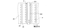
第1の搬送装置20は、供給ドラム13や中間ドラム14と同様にドラム状に形成されており、図2に一部を切り欠いて示すように、被印刷物Pを保持する保持部22が、外周面の周方向および回転軸方向の双方に沿って等間隔に多数設けられている。保持部22は、底部に吸引孔24が形成されており、真空吸引装置(図示せず)により第1の搬送装置20の内部を減圧することにより、保持部22に収容された被印刷物Pを吸引孔24を介して吸引保持し、被印刷物Pの方向が搬送中に変化するのを防止しつつ、被印刷物Pを第1の搬送装置20の回転方向に沿って搬送することができる。
The
第2の搬送装置30は、第1の搬送装置20と同様に構成されており、ドラム状の外周面に保持部32が形成されている。第1の搬送装置20により搬送される被印刷物は、第2の搬送装置30に引き渡される際に表裏が反転されて、排出装置40に搬送される。
The
上記の構成を備えるインクジェットマーキング装置1において、第1の搬送装置20の近傍には、第1の検出装置210、第1の印刷装置220および第1の印刷検査装置230が、第1の搬送装置20の搬送方向に沿って順次設けられている。
In the
第1の検出装置210は、検出エリアに搬送された被印刷物に照明光を照射する照射部212と、照射部212の照射方向とは異なる方向から被印刷物を撮像するCCDエリアカメラやCCDラインカメラなどの撮像部214とを備えている。照射部212は、例えばリング照明であり、被印刷物を全周から均一に照射することができる。第1の検出装置210は、第1の搬送装置20の保持部22に被印刷物Pが保持されているか否かを検出すると共に、被印刷物Pが保持されている場合には、被印刷物Pの位置や方向を判別するために、被印刷物Pの割線、凹部、外形線(輪郭線)などを検出する。
The
第1の印刷装置220は、第1の搬送装置20の回転軸方向に沿って延びるガイドレール221に移動可能に支持された印刷ヘッド222を備えている。印刷ヘッド222は、第1の搬送装置20と対向する面に多数(例えば、数百個程度)のノズル224を備えており、第1の搬送装置20により印刷領域Aに搬送された被印刷物Pに対してインクジェット方式による印刷を行い、被印刷物Pの表面にマーキングパターンを形成する。ノズル224の配列方向は、印刷ヘッド222の移動方向に略一致しており、本実施形態においては被印刷物Pの搬送方向と直交しているが、被印刷物Pの搬送方向と交差する方向であれば必ずしも直交方向に限定されるものではない。
The
図3は、第1の搬送装置20の外周面の一部を平面的に表した展開図である。第1の搬送装置20の各保持部22は、被印刷物Pを収容可能に形成され、搬送方向と直交する方向に列状に設けられており、各列が搬送方向に間隔をあけて配置されている。第1の印刷装置の印刷ヘッド222は、印刷領域Aに搬送された保持部22の一列全体をカバーするように配置されており、矢示のようにガイドレール221に沿って往復動可能とされている。
FIG. 3 is a development view illustrating a part of the outer peripheral surface of the
第1の印刷検査装置230は、検査エリアに搬送された被印刷物に照明光を照射する照射部232と、被印刷物を撮像するCCDエリアカメラやCCDラインカメラなどの撮像部234とを備えており、第1の検出装置210が検出した被印刷物Pの位置および方向に基づいて、被印刷物に形成されたマーキングパターンの検査を行う。
The first
また、第2の搬送装置30の近傍には、第2の検出装置310、第2の印刷装置320および第2の印刷検査装置330が、第2の搬送装置30の搬送方向に沿って順次設けられている。第2の検出装置310、第2の印刷装置320および第2の印刷検査装置330の構成は、それぞれ第1の検出装置210、第1の印刷装置220および第1の印刷検査装置230と同様であり、第2の検出装置310が照射部312および撮像部314を備え、第2の印刷検査装置330が照射部332および撮像部334を備えている。第2の搬送装置30は、第1の搬送装置20から被印刷物を受け取って搬送し、第1の搬送装置20による搬送中にマーキングパターンが形成された面とは反対側の面に、第2の検出装置310、第2の印刷装置320および第2の印刷検査装置330により被印刷物Pの検出、マーキングパターンの形成およびマーキング検査が順次行われる。
Further, a
排出装置40は、第1の印刷検査装置230および第2の印刷検査装置330におけるマーキング検査の結果に基づいて被印刷物の振り分けを行う振り分け部42を備えており、良品のみを排出コンベア44に案内して排出する。
The
図4は、上述したインクジェットマーキング装置1の全体構成を示すブロック図である。第1の検出装置210、第1の印刷検査装置230、第2の検出装置310および第2の印刷検査装置330の検出結果は、制御装置50に入力される。制御装置50は、供給装置10、第1の搬送装置20、第2の搬送装置30、排出装置40、第1の印刷装置220および第2の印刷装置320の作動を制御する。
FIG. 4 is a block diagram showing the overall configuration of the
次に、上記の構成を備えるインクジェットマーキング装置1を用いて被印刷物にマーキングを行う方法の一例を、図5に示すフローチャートを参照しながら説明する。錠剤である被印刷物Pが、供給装置10から第1の搬送装置20に供給されると(ステップS1)、被印刷物Pは、図6(a)に示すように、第1の搬送装置20の搬送方向と直交する方向に整列した状態となるように、個別に保持部22に収容される。被印刷物Pに割線Cが形成されている場合、それぞれの被印刷物Pに形成された割線Cの方向はランダムである。
Next, an example of a method for marking an object to be printed using the
被印刷物Pが第1の検出装置210の検出エリアに搬送されると(ステップS2)、撮像部214が、保持部22に被印刷物Pが保持されているか否かを検出する(ステップS3)。制御装置50は、被印刷物Pが存在する場合には、被印刷物Pの画像データを取得し、割線Cの検出により各被印刷物Pの位置データおよび方向データ(X,Y,θ)を取得する(ステップS4)。なお、取得した画像データに割線Cが存在しない被印刷物Pについては、その旨が方向データの代わりに出力される。
When the printing material P is conveyed to the detection area of the first detection device 210 (step S2), the
ついで、被印刷物Pが第1の印刷装置220の印刷領域Aに搬送されると、図6(b)に示すように、各被印刷物Pの位置および方向に合わせてマーキングパターンMの形成が行われる(ステップS5)。制御装置50は、文字、数字、記号、図形等やこれらの組み合わせからなるマーキングパターンの基準座標系での座標データが、メモリ部に予め格納されており、第1の検出装置210から入力された被印刷物毎の位置データおよび方向データに基づいて、使用する印刷ヘッド222のノズル224を選択し、インクジェット印刷を行う。
Next, when the substrate P is conveyed to the printing area A of the
使用するノズル224および各ノズル224の噴射時間は、被印刷物Pの位置や方向によって異なる。例えば、図7(a)に示すように、被印刷物Pの位置および方向が基準位置および基準方向と一致する場合に、ノズル224−1によって直線状のマーキングパターンMが形成されるとすると、第1の検出装置210で取得した被印刷物Pの位置データ(搬送方向と直交するX方向のデータ)が基準位置からずれている場合に、図7(b)に示すように、このずれ量に対応して選択されたノズル224−2を使用してマーキングを行う。また、第1の検出装置210で取得した被印刷物Pの方向データ(基準位置を原点とするθ方向のデータ)が基準方向からずれている場合に、図7(c)に示すように、このずれ量に対応して使用するノズル224−3を拡げて、マーキングを行う。
The
被印刷物Pに対してマーキングパターンを形成した後、被印刷物Pが第1の印刷検査装置230の検査エリアに搬送されると、撮像部234が、列ごとの被印刷物Pの画像データを取得する。制御装置50は、この画像データを予め設定された基準パターンデータと比較して、パターンマッチング等の公知の検査方法によりマーキング精度の検査を行う(ステップS6)。
After the marking pattern is formed on the printing material P, when the printing material P is conveyed to the inspection area of the first
こうして、供給装置10から第1の搬送装置20に被印刷物Pが連続的に供給され、これらの被印刷部Pが第1の印刷装置220に搬送されてマーキングパターンの形成が順次行われるが、被印刷物Pに対するマーキングを繰り返し行うと、使用するノズル224に偏りが生じて使用頻度の少ないノズル224にノズル詰まりが発生するおそれがある。このため、制御装置50は、ノズル替えが必要になったか否かを判別し(ステップS7)、ノズル替え時の場合には、供給装置10において、供給ドラム13の回転を一時的に停止させる(ステップS8)。これにより、中間ドラム14の保持部14aに、被印刷物Pが保持されない非保持領域が形成され、第1の搬送装置20にも、保持部22に被印刷物Pが保持されない非保持領域が形成される。なお、供給ドラム13から第1の搬送装置20への被印刷物Pの供給は、中間ドラム14を介さず直接行うように構成することもできる。
In this way, the printing material P is continuously supplied from the
制御装置50によるノズル替え時期の判別方法は、特に限定されるものではないが、例えば、第1の印刷装置220における印刷個数が、統計的に予め設定された回数に到達したか否かで行うことができ、あるいは、各ノズル224の使用頻度を常時検出しておき、使用頻度に所定の偏りが生じたか否かで行うこともできる。
The method for determining the nozzle replacement time by the
図8に示すように、第1の搬送装置20に形成された非保持領域Nは、第1の検出装置210において検出される。保持部22に被印刷物Pが保持されていないことを第1の搬送装置20が検出すると(ステップS3)、制御装置50は、この非保持領域Nが第1の印刷装置220を通過する間、マーキングを行わずに印刷ヘッド222を移動する(ステップS9)。これにより、第1の印刷装置220における次回以降のマーキングは、使用するノズル224を変更して行うことができる。第1の搬送装置20に形成する非保持領域Nは、本実施形態では保持部22の一列のみとしているが、印刷ヘッド222の移動に必要な時間を考慮して、保持部22の複数列を非保持領域Nとすることもできる。
As shown in FIG. 8, the non-holding area N formed in the
ノズル替え時における印刷ヘッド222の移動方向および移動量は、基準位置および基準方向の被印刷物Pに対して、使用頻度の少ないノズル224が最も使用されるように設定することが好ましい。例えば、図9(a)に示すように、被印刷物Pの位置および方向が基準位置および基準方向と一致する場合に、ノズル224−1によって直線状のマーキングパターンMが形成されるとすると、図9(b)に示すように印刷ヘッド222を右方向に移動させることにより、基準位置および基準方向の被印刷物Pに使用するノズルは、もとのノズル224−1よりも左側にある他のノズル224−4に変更される。一方、図9(c)に示すように印刷ヘッド222を左方向に移動させると、基準位置および基準方向の被印刷物Pに使用するノズルは、もとのノズル224−1よりも右側にある他のノズル224−5に変更される。基準位置および基準方向で使用するノズル224は、印刷ヘッド222の移動量によっても調整することが可能であり、使用頻度が最も少ないノズル224を対象として印刷ヘッド222を移動させることで、ノズル替えを効果的に行うことができる。
It is preferable to set the moving direction and moving amount of the
こうして、被印刷物Pの一方面に対するマーキングおよび検査が行われた後、被印刷物Pが第1の搬送装置20から第2の搬送装置30に引き渡され、第2の検出装置310、第2の印刷装置320および第2の印刷検査装置330に順次搬送されることにより、上記と同様にして、被印刷物Pの他方面に対するマーキングおよびマーキング検査が行われる。すなわち、第2の印刷装置320においては、第2の検出装置310が取得した位置データおよび方向データに基づいて被印刷物へのマーキングが行われ、第2の印刷検査装置330においては、第2の検出装置310の検出データに基づいてマーキング精度の検査が行われる。被印刷物Pの他方面に対する印刷処理も、図5に示すフローチャートに従って、上記と同様の手順により行うことができ、第2の搬送装置30に形成される非保持領域を利用して、ノズル替えを適宜行うことができる。
Thus, after marking and inspection are performed on one surface of the printing material P, the printing material P is transferred from the
この後、被印刷物Pは、第2の搬送装置30から排出装置40に搬送される。排出装置40には、第1の印刷検査装置230および第2の印刷検査装置330から、被印刷物P毎のマーキング良否判定データが入力され、良品と判定された被印刷物Pが、振り分け部42を経て排出コンベア44に案内される一方、不良品と判定された被印刷物Pは、不良排出部45においてエアで吹き出されて不良排出シュート46に案内される。不良排出確認センサ47は、不良判定された被印刷物Pが第2の搬送装置30に残留していないかをチェックし、不良の被印刷物Pが残留していた場合に、振り分け部42において被印刷物Pを廃棄シュート48に案内する。
Thereafter, the printing material P is transported from the
本実施形態のインクジェットマーキング装置1によれば、第1の印刷検査装置230および第2の印刷検査装置330で使用するノズルを変更するノズル替え時において、供給装置10が備える供給ドラム13の作動を一時的に停止して、被印刷物Pが第1の搬送装置20および第2の搬送装置30の保持部22,32に保持されない非保持領域Nを形成し、被印刷物PにマーキングパターンMを形成した後、非保持領域Nが印刷領域Aを通過する間に印刷ヘッド222,322を移動させるように構成しているので、第1の搬送装置20および第2の搬送装置30による被印刷物Pの高速搬送を維持しつつ、ノズル替えに必要な印刷ヘッド222,322の移動時間を確保することができる。したがって、使用するノズル224,324の均一化を図ることで、ノズル詰まりを効果的に防止することができ、多量の被印刷物Pに対して迅速且つ確実にマーキングを行うことができる。
According to the
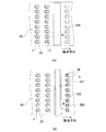
以上、本発明の一実施形態について詳述したが、本発明の具体的な態様は上記実施形態に限定されるものではない。例えば、本実施形態においては、第1の搬送装置20および第2の搬送装置30をいずれも搬送ドラムとしているが、保持した被印刷物の姿勢が搬送中に変化しない構成であれば、他の構成であってもよい。例えば、図10(a)および図10(b)に示すように、第1の搬送装置20および第2の搬送装置30を、いずれもスラットコンベアやベルトコンベアなどのコンベア装置として、第1の搬送装置20により水平搬送される被印刷物を、反転機構60により表裏反転させて、第2の搬送装置30に搭載して水平搬送することで、本実施形態と同様に、被印刷物の表裏両面にマーキングを行うことができる。また、図10(c)に示すように、第2の搬送装置30を、上方から被印刷物を真空吸引可能な吸引孔を有する吸引ベルトにより構成し、第1の搬送装置20により水平搬送される被印刷物を第2の搬送装置30に吸着保持させて下方からマーキングを行うことにより、被印刷物の表裏両面にマーキングを行うこともできる。図10(a)から(c)において、図1と同様の構成部分には同一の符号を付している。供給装置10についても、供給ドラム13を備える代わりに、コンベア状の構成であってもよい。マーキングの形成は、被印刷物の一方面のみに行う構成であってもよく、第2の搬送装置30、第2の検出装置310、第2の印刷装置320および第2の印刷検査装置330を備えない構成であってもよい。
As mentioned above, although one Embodiment of this invention was explained in full detail, the specific aspect of this invention is not limited to the said embodiment. For example, in the present embodiment, both the
1 インクジェットマーキング装置
10 供給装置
13 供給ドラム
20 第1の搬送装置
210 第1の検出装置
220 第1の印刷装置
222 印刷ヘッド
224 ノズル
230 第1の印刷検査装置
30 第2の搬送装置
310 第2の検出装置
320 第2の印刷装置
322 印刷ヘッド
324 ノズル
330 第2の印刷検査装置
DESCRIPTION OF
Claims (6)
前記保持部に被印刷物を供給する供給手段と、
前記搬送手段により印刷領域に搬送された被印刷物にインクジェット方式によるマーキングパターンを形成する印刷手段と、
前記搬送手段、供給手段および印刷手段の作動を制御する制御手段とを備え、
前記印刷手段は、前記被印刷物の搬送方向と交差する方向に沿ってノズルが複数設けられた印刷ヘッドを備え、前記印刷ヘッドは、前記ノズルの配列方向に沿って移動可能に支持されており、
前記制御手段は、使用する前記ノズルを変更するノズル替え時において、前記供給手段の作動を一時的に停止して被印刷物が前記保持部に保持されない非保持領域を前記搬送手段に形成し、被印刷物への印刷後、前記非保持領域が前記印刷領域を通過する間に前記印刷ヘッドを移動させる、インクジェットマーキング装置。 Conveying means in which a plurality of holding parts for holding the printing material are formed at intervals in the conveying direction;
Supply means for supplying a substrate to the holding unit;
A printing means for forming a marking pattern by an ink jet method on a printing material conveyed to the printing region by the conveying means;
Control means for controlling the operation of the transport means, supply means and printing means,
The printing unit includes a print head provided with a plurality of nozzles along a direction intersecting a conveyance direction of the substrate, and the print head is supported to be movable along an arrangement direction of the nozzles.
The control means temporarily stops the operation of the supply means at the time of nozzle change to change the nozzle to be used, and forms a non-holding area in the transport means where the printed material is not held by the holding portion. An inkjet marking apparatus that moves the print head after the non-holding area passes through the printing area after printing on a printed matter.
前記制御手段は、前記供給ドラムの回転を一時的に停止して、前記搬送手段に前記非保持領域を形成する請求項1から3のいずれかに記載のインクジェットマーキング装置。 The supply means includes a supply drum having a plurality of holding portions formed on the outer peripheral surface corresponding to the intervals of the holding portions provided in the transport means,
4. The inkjet marking device according to claim 1, wherein the control unit temporarily stops the rotation of the supply drum to form the non-holding region in the transport unit. 5.
前記制御手段は、前記検出手段による前記非保持領域の検出に基づいて前記印刷ヘッドを移動させる請求項1から4のいずれかに記載のインクジェットマーキング装置。 Further comprising detection means for detecting the non-holding area before the holding part passes through the printing area;
The inkjet marking apparatus according to claim 1, wherein the control unit moves the print head based on detection of the non-holding area by the detection unit.
前記保持部に保持された被印刷物を、前記搬送手段の作動により印刷手段の印刷領域に搬送する搬送ステップと、
前記印刷領域に搬送された被印刷物に、インクジェット方式によるマーキングパターンを形成する印刷ステップとを備え、
前記印刷手段は、前記被印刷物の搬送方向と交差する方向に沿ってノズルが複数設けられた印刷ヘッドを備え、前記印刷ヘッドは、前記ノズルの配列方向に沿って移動可能に支持されており、
前記供給ステップは、前記印刷ステップにおいて使用する前記ノズルを変更するノズル替え時において、前記保持部への被印刷物の供給を一時的に停止して、被印刷物が前記保持部に保持されない非保持領域を前記搬送手段に形成し、
前記印刷ステップは、被印刷物への印刷後、前記非保持領域が前記印刷領域を通過する間に前記印刷ヘッドを移動させる、インクジェットマーキング方法。 A supply step of supplying the printing material to the holding unit of the conveying means in which a plurality of holding units holding the printing material are formed at intervals in the conveying direction;
A transporting step of transporting the substrate to be printed held by the holding unit to a printing region of the printing unit by the operation of the transporting unit;
A printing step of forming a marking pattern by an ink jet method on the substrate transported to the printing region,
The printing unit includes a print head provided with a plurality of nozzles along a direction intersecting a conveyance direction of the substrate, and the print head is supported to be movable along an arrangement direction of the nozzles.
The supply step temporarily stops the supply of the printing material to the holding unit when the nozzle is changed to change the nozzle used in the printing step, and the non-holding region where the printing material is not held by the holding unit Is formed on the conveying means,
The printing step is an ink jet marking method in which, after printing on a substrate, the print head is moved while the non-holding area passes through the printing area.
Priority Applications (10)
| Application Number | Priority Date | Filing Date | Title |
|---|---|---|---|
| JP2014064916A JP6245754B2 (en) | 2014-03-27 | 2014-03-27 | Inkjet marking apparatus and method |
| MX2016012561A MX2016012561A (en) | 2014-03-27 | 2015-03-02 | Inkjet marking device and method. |
| BR112016021645-8A BR112016021645B1 (en) | 2014-03-27 | 2015-03-02 | INK JET MARKING DEVICE AND METHOD |
| KR1020167025802A KR102312064B1 (en) | 2014-03-27 | 2015-03-02 | Inkjet marking device and method |
| US15/125,408 US9649864B2 (en) | 2014-03-27 | 2015-03-02 | Inkjet marking device and method |
| CA2940005A CA2940005C (en) | 2014-03-27 | 2015-03-02 | Inkjet marking device and method |
| EP15770120.2A EP3124248B1 (en) | 2014-03-27 | 2015-03-02 | Inkjet marking device and method |
| PCT/JP2015/056030 WO2015146493A1 (en) | 2014-03-27 | 2015-03-02 | Inkjet marking device and method |
| CN201580016713.XA CN106132711B (en) | 2014-03-27 | 2015-03-02 | Inkjet-printing device and method |
| IL247416A IL247416B (en) | 2014-03-27 | 2016-08-22 | Inkjet marking device and method |
Applications Claiming Priority (1)
| Application Number | Priority Date | Filing Date | Title |
|---|---|---|---|
| JP2014064916A JP6245754B2 (en) | 2014-03-27 | 2014-03-27 | Inkjet marking apparatus and method |
Publications (2)
| Publication Number | Publication Date |
|---|---|
| JP2015186783A JP2015186783A (en) | 2015-10-29 |
| JP6245754B2 true JP6245754B2 (en) | 2017-12-13 |
Family
ID=54195024
Family Applications (1)
| Application Number | Title | Priority Date | Filing Date |
|---|---|---|---|
| JP2014064916A Active JP6245754B2 (en) | 2014-03-27 | 2014-03-27 | Inkjet marking apparatus and method |
Country Status (10)
| Country | Link |
|---|---|
| US (1) | US9649864B2 (en) |
| EP (1) | EP3124248B1 (en) |
| JP (1) | JP6245754B2 (en) |
| KR (1) | KR102312064B1 (en) |
| CN (1) | CN106132711B (en) |
| BR (1) | BR112016021645B1 (en) |
| CA (1) | CA2940005C (en) |
| IL (1) | IL247416B (en) |
| MX (1) | MX2016012561A (en) |
| WO (1) | WO2015146493A1 (en) |
Families Citing this family (9)
| Publication number | Priority date | Publication date | Assignee | Title |
|---|---|---|---|---|
| DE19649864A1 (en) * | 1996-12-02 | 1998-06-04 | Graaff Vertriebs Gmbh | Automatic drainage device for freight containers or other cargo-receiving rooms |
| JP2017158947A (en) * | 2016-03-11 | 2017-09-14 | フロイント産業株式会社 | Tablet printing device, tablet printing method, and medicine management system |
| KR102424144B1 (en) | 2016-11-30 | 2022-07-21 | 쿠오리카프스 가부시키가이샤 | Formulation conveying device and formulation printing device |
| WO2018146983A1 (en) * | 2017-02-12 | 2018-08-16 | フロイント産業株式会社 | Solid preparation printing method and solid preparation printer |
| JP6930708B2 (en) * | 2017-02-12 | 2021-09-01 | フロイント産業株式会社 | Solid product printing method and solid product printing machine |
| JP2019202506A (en) * | 2018-05-25 | 2019-11-28 | 株式会社Screenホールディングス | Printing method, printer and granular material |
| US11135854B2 (en) * | 2018-12-06 | 2021-10-05 | Kateeva, Inc. | Ejection control using imager |
| JP7306929B2 (en) * | 2019-09-13 | 2023-07-11 | 株式会社Screenホールディングス | Conveyance processing device and conveyance processing method |
| JP7065820B2 (en) * | 2019-11-18 | 2022-05-12 | Ckd株式会社 | PTP packaging machine and PTP sheet manufacturing method |
Family Cites Families (16)
| Publication number | Priority date | Publication date | Assignee | Title |
|---|---|---|---|---|
| JP2001040520A (en) * | 1999-07-28 | 2001-02-13 | Mitsubishi Rayon Co Ltd | Method for exchanging shaping nozzle, and apparatus for shaping molten resin |
| EP1900533A1 (en) * | 2006-09-16 | 2008-03-19 | J. Zimmer Maschinenbau Gesellschaft m.b.H. | Apparatus for applying substance to planar substrates |
| JP5281238B2 (en) * | 2006-11-24 | 2013-09-04 | エーザイ・アール・アンド・ディー・マネジメント株式会社 | Laser marking device for edible bodies |
| JP2008279640A (en) * | 2007-05-09 | 2008-11-20 | Mimaki Engineering Co Ltd | Device and method for controlling inkjet printer |
| JP4304218B2 (en) * | 2007-06-07 | 2009-07-29 | セイコープレシジョン株式会社 | Printing apparatus, printing method, and program |
| EP2184047A4 (en) * | 2007-08-22 | 2010-12-15 | Astellas Pharma Inc | Tablet printing system and tablet production method and tablet |
| JP5092783B2 (en) * | 2008-02-15 | 2012-12-05 | セイコーエプソン株式会社 | Fluid discharge device |
| JP5469389B2 (en) * | 2009-07-15 | 2014-04-16 | 株式会社京都製作所 | Tablet printing method and tablet printing apparatus |
| KR101110781B1 (en) | 2009-08-22 | 2012-03-13 | 정세헌 | A manufacturing method of functional korean hot pepper paste and thereby korean hot pepper paste |
| JP5904719B2 (en) * | 2011-05-06 | 2016-04-20 | クオリカプス株式会社 | Marked capsule, capsule manufacturing method, and capsule |
| US20120293649A1 (en) * | 2011-05-17 | 2012-11-22 | Gii Acquisition, Llc Dba General Inspection, Llc | Method and system for inspecting dosage forms having code imprints and sorting the inspected dosage forms |
| JP5752081B2 (en) * | 2011-06-09 | 2015-07-22 | 株式会社京都製作所 | Tablet printing apparatus and tablet printing method |
| JP5335040B2 (en) * | 2011-07-22 | 2013-11-06 | 富士フイルム株式会社 | Image forming apparatus and image forming method |
| JP5688770B2 (en) * | 2011-12-09 | 2015-03-25 | 株式会社京都製作所 | Tablet printer |
| JP5884642B2 (en) * | 2012-05-29 | 2016-03-15 | ブラザー工業株式会社 | Image recording device |
| JP6459526B2 (en) * | 2014-04-24 | 2019-01-30 | セイコーエプソン株式会社 | Liquid ejection device and liquid ejection method |
-
2014
- 2014-03-27 JP JP2014064916A patent/JP6245754B2/en active Active
-
2015
- 2015-03-02 EP EP15770120.2A patent/EP3124248B1/en active Active
- 2015-03-02 US US15/125,408 patent/US9649864B2/en active Active
- 2015-03-02 CA CA2940005A patent/CA2940005C/en active Active
- 2015-03-02 BR BR112016021645-8A patent/BR112016021645B1/en active IP Right Grant
- 2015-03-02 KR KR1020167025802A patent/KR102312064B1/en active IP Right Grant
- 2015-03-02 MX MX2016012561A patent/MX2016012561A/en active IP Right Grant
- 2015-03-02 WO PCT/JP2015/056030 patent/WO2015146493A1/en active Application Filing
- 2015-03-02 CN CN201580016713.XA patent/CN106132711B/en active Active
-
2016
- 2016-08-22 IL IL247416A patent/IL247416B/en active IP Right Grant
Also Published As
| Publication number | Publication date |
|---|---|
| EP3124248B1 (en) | 2018-11-21 |
| IL247416A0 (en) | 2016-11-30 |
| BR112016021645B1 (en) | 2022-02-15 |
| WO2015146493A1 (en) | 2015-10-01 |
| CA2940005C (en) | 2021-09-21 |
| IL247416B (en) | 2020-04-30 |
| CN106132711B (en) | 2017-10-03 |
| KR102312064B1 (en) | 2021-10-12 |
| KR20160138021A (en) | 2016-12-02 |
| US20170096020A1 (en) | 2017-04-06 |
| MX2016012561A (en) | 2016-12-14 |
| EP3124248A4 (en) | 2017-12-20 |
| BR112016021645A2 (en) | 2017-08-15 |
| US9649864B2 (en) | 2017-05-16 |
| CA2940005A1 (en) | 2015-10-01 |
| EP3124248A1 (en) | 2017-02-01 |
| JP2015186783A (en) | 2015-10-29 |
| CN106132711A (en) | 2016-11-16 |
Similar Documents
| Publication | Publication Date | Title |
|---|---|---|
| JP6245754B2 (en) | Inkjet marking apparatus and method | |
| JP6402105B2 (en) | Edible body marking apparatus and method | |
| JP6297428B2 (en) | Tablet printing apparatus and tablet printing method | |
| TWI611937B (en) | Tablet printing apparatus and tablet printing method | |
| JP2011020325A (en) | Printing method and printer | |
| JP2017124171A (en) | Tablet printing device | |
| KR20200034594A (en) | Transport apparatus and transport method | |
| JP7186325B2 (en) | edible marking device | |
| JP2018183671A (en) | Tablet printing method | |
| JP6397061B2 (en) | Tablet printing method | |
| WO2019155680A1 (en) | Determination device, determination method, tablet printing device, and tablet printing method | |
| JP2019080987A (en) | Tablet printing device | |
| KR20190123234A (en) | Vibration feeder and printing apparatus | |
| JP2023104884A (en) | Information processing device, information processing method, and tablet printing device | |
| JP2022076140A (en) | Printed edible body manufacturing method and manufacturing device | |
| JP2023050476A (en) | Tablet printing device and tablet printing method | |
| JP2020039946A (en) | Tablet printing method | |
| JP2017080502A (en) | Tablet printing device |
Legal Events
| Date | Code | Title | Description |
|---|---|---|---|
| A621 | Written request for application examination |
Free format text: JAPANESE INTERMEDIATE CODE: A621 Effective date: 20170124 |
|
| TRDD | Decision of grant or rejection written | ||
| A01 | Written decision to grant a patent or to grant a registration (utility model) |
Free format text: JAPANESE INTERMEDIATE CODE: A01 Effective date: 20171110 |
|
| A61 | First payment of annual fees (during grant procedure) |
Free format text: JAPANESE INTERMEDIATE CODE: A61 Effective date: 20171113 |
|
| R150 | Certificate of patent or registration of utility model |
Ref document number: 6245754 Country of ref document: JP Free format text: JAPANESE INTERMEDIATE CODE: R150 |
|
| R250 | Receipt of annual fees |
Free format text: JAPANESE INTERMEDIATE CODE: R250 |
|
| R250 | Receipt of annual fees |
Free format text: JAPANESE INTERMEDIATE CODE: R250 |