<第1の実施形態>
第1の実施形態について図1から図5を参照して説明する。
<First Embodiment>
A first embodiment will be described with reference to FIGS. 1 to 5. FIG.
(錠剤印刷装置の構成例)
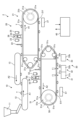
図1に示すように、第1の実施形態に係る錠剤印刷装置1は、供給装置10と、印刷装置20と、回収装置30と、制御装置40とを備える。
(Configuration example of tablet printing device)
As shown in FIG. 1, the tablet printing apparatus 1 according to the first embodiment includes a supply device 10, a printing device 20, a recovery device 30, and a control device 40.
供給装置10は、ホッパ11、整列フィーダ12及び受渡フィーダ13を有している。この供給装置10は、印刷装置20の一端側に位置付けられ、印刷対象物である錠剤Tを印刷装置20に供給することが可能に構成されている。ホッパ11は、多数の錠剤Tを収容し、収容した錠剤Tを整列フィーダ12に順次供給する。整列フィーダ12は、供給された錠剤Tを一列に整列し、受渡フィーダ13に向けて搬送方向A1(時計回り方向)に搬送する。受渡フィーダ13は、整列フィーダ12上に一列に並ぶ各錠剤Tを錠剤Tの上側から順次吸引して保持し、保持した各錠剤Tを印刷装置20まで一列で搬送して印刷装置20に渡す。整列フィーダ12としては、例えばベルト搬送機構や振動フィーダが用いられる。受渡フィーダ13としては、例えばベルト搬送機構が用いられる。この受渡フィーダ13のベルト搬送機構は、搬送方向A2(反時計回り方向)に回転している。供給装置10は制御装置40に電気的に接続されており、その駆動が制御装置40により制御される。
The supply device 10 has a hopper 11 , an alignment feeder 12 and a delivery feeder 13 . The supply device 10 is positioned on one end side of the printing device 20 and is configured to be able to supply tablets T, which are objects to be printed, to the printing device 20 . The hopper 11 accommodates a large number of tablets T and sequentially supplies the accommodated tablets T to the alignment feeder 12 . The aligning feeder 12 aligns the supplied tablets T in a row and conveys them toward the delivery feeder 13 in the conveying direction A1 (clockwise direction). The delivery feeder 13 sequentially sucks and holds the tablets T arranged in a line on the alignment feeder 12 from the upper side of the tablets T, conveys the held tablets T in a line to the printing device 20, and delivers them to the printing device 20. - 特許庁As the alignment feeder 12, for example, a belt conveying mechanism or a vibrating feeder is used. A belt conveying mechanism, for example, is used as the delivery feeder 13 . The belt conveying mechanism of the delivery feeder 13 rotates in the conveying direction A2 (counterclockwise direction). The supply device 10 is electrically connected to the control device 40 and its driving is controlled by the control device 40 .
印刷装置20は、搬送部21と、検出部22と、第1の撮像部23と、インクジェットヘッド24と、第2の撮像部25と、移動機構26と、乾燥部27とを備える。
The printing device 20 includes a transport section 21 , a detection section 22 , a first imaging section 23 , an inkjet head 24 , a second imaging section 25 , a moving mechanism 26 and a drying section 27 .
搬送部21は、搬送ベルト21a、駆動プーリ21b、複数の従動プーリ21c、モータ21d、位置検出器21e及び吸引チャンバ21fを有する。搬送ベルト21aは、無端状のベルトであり、駆動プーリ21b及び各従動プーリ21cに架け渡されている。駆動プーリ21b及び各従動プーリ21cは装置本体(図示せず)に回転可能に設けられており、駆動プーリ21bはモータ21dに連結されている。モータ21dは制御装置40に電気的に接続されており、その駆動が制御装置40により制御される。位置検出器21eは、エンコーダなどの機器であり、モータ21dに取り付けられている。この位置検出器21eは電気的に制御装置40に接続されており、検出信号を制御装置40に送信する。搬送部21は、モータ21dによる駆動プーリ21bの回転によって各従動プーリ21cと共に搬送ベルト21aを走行させ、搬送ベルト21a上の錠剤Tを搬送方向A1(時計回り方向)に搬送する。
The transport section 21 has a transport belt 21a, a driving pulley 21b, a plurality of driven pulleys 21c, a motor 21d, a position detector 21e, and a suction chamber 21f. The conveying belt 21a is an endless belt, and is stretched over the driving pulley 21b and the driven pulleys 21c. The drive pulley 21b and the driven pulleys 21c are rotatably provided in the apparatus main body (not shown), and the drive pulley 21b is connected to the motor 21d. The motor 21 d is electrically connected to the control device 40 and its drive is controlled by the control device 40 . The position detector 21e is a device such as an encoder, and is attached to the motor 21d. This position detector 21 e is electrically connected to the control device 40 and transmits a detection signal to the control device 40 . The transport unit 21 runs the transport belt 21a together with the driven pulleys 21c by rotating the drive pulley 21b by the motor 21d, and transports the tablets T on the transport belt 21a in the transport direction A1 (clockwise direction).
搬送ベルト21aには、図2に示すように、円形状の吸引孔21gが複数形成されている。これらの吸引孔21gは、それぞれ錠剤Tを吸着する貫通孔であり、一本の搬送路を形成するように搬送方向A1に沿って一列に並べられている。各吸引孔21gは、吸引チャンバ21f(図1参照)に形成された吸引路(図示せず)を介して吸引チャンバ21f内に接続されており、吸引チャンバ21fにより吸引力を得ることが可能になっている。吸引チャンバ21fには、ポンプが吸引管(いずれも図示せず)を介して接続されており、ポンプの作動により吸引チャンバ21f内が減圧される。吸引管は、吸引チャンバ21fの側面(搬送方向A1と平行な面)の略中央に接続されている。また、ポンプは制御装置40に電気的に接続されており、その駆動が制御装置40により制御される。吸引チャンバ21f内が減圧されると、搬送ベルト21aの各吸引孔21g上に置かれた錠剤Tは吸引孔21gにより吸引され、搬送ベルト21a上に保持される。
As shown in FIG. 2, a plurality of circular suction holes 21g are formed in the conveying belt 21a. These suction holes 21g are through holes for sucking tablets T, and are arranged in a line along the transport direction A1 so as to form a single transport path. Each suction hole 21g is connected to the inside of the suction chamber 21f via a suction path (not shown) formed in the suction chamber 21f (see FIG. 1), so that a suction force can be obtained by the suction chamber 21f. It's becoming A pump is connected to the suction chamber 21f via a suction pipe (both not shown), and the pressure in the suction chamber 21f is reduced by the operation of the pump. The suction pipe is connected to substantially the center of the side surface (surface parallel to the transport direction A1) of the suction chamber 21f. Also, the pump is electrically connected to the control device 40 and its driving is controlled by the control device 40 . When the suction chamber 21f is decompressed, the tablets T placed on the suction holes 21g of the conveyor belt 21a are sucked by the suction holes 21g and held on the conveyor belt 21a.
検出部22は、供給装置10が設けられた位置よりも搬送方向A1の下流側に位置付けられ、吸引孔21gで形成される搬送路の上方に設けられている。この検出部22は、レーザ光の投受光によって検出部22の直下の検出位置に到達した錠剤T(錠剤Tの到来)、すなわち搬送ベルト21a上の錠剤TのX方向(図2参照)の位置を検出する。また、検出部22は、搬送ベルト21a上の錠剤Tの高さを検出する。検出部22としては、例えば、変位センサが用いられる。また、変位センサとしては、反射型レーザセンサなどの各種のレーザセンサが用いられる。検出部22は制御装置40に電気的に接続されており、制御装置40に検出信号を送信する。
The detection unit 22 is positioned downstream in the transport direction A1 from the position where the supply device 10 is provided, and is provided above the transport path formed by the suction holes 21g. The detection unit 22 detects the position of the tablet T in the X direction (see FIG. 2) of the tablet T on the conveyor belt 21a that has reached the detection position directly below the detection unit 22 (the arrival of the tablet T). to detect Further, the detection unit 22 detects the height of the tablets T on the conveying belt 21a. For example, a displacement sensor is used as the detection unit 22 . Various laser sensors such as a reflective laser sensor are used as the displacement sensor. The detector 22 is electrically connected to the control device 40 and transmits a detection signal to the control device 40 .
第1の撮像部23は、検出部22が設けられた位置よりも搬送方向A1の下流側に位置付けられ、吸引孔21gで形成される搬送路の上方に設けられている。この第1の撮像部23は、検出部22により検出された錠剤TのX方向の位置情報に基づき、錠剤Tが第1の撮像部23の直下の撮像位置に到達した第1の撮像タイミングで撮像を行い、錠剤Tの上面を含む第1の画像を取得し、取得した第1の画像を制御装置40に送信する。第1の画像は、錠剤TのX方向、Y方向及びθ方向(図2参照)の位置を検出するため、また、錠剤Tの損傷や異物付着(例えば、割れや欠け、汚れなど)の有無を検出するために用いられる。第1の撮像部23としては、CCD(電荷結合素子)やCMOS(相補型金属酸化膜半導体)などの撮像素子を有する各種のカメラが用いられる。第1の撮像部23は制御装置40に電気的に接続されており、その駆動が制御装置40により制御される。なお、必要に応じて撮像用の照明も設けられる。
The first imaging unit 23 is positioned downstream in the transport direction A1 from the position where the detection unit 22 is provided, and is provided above the transport path formed by the suction holes 21g. Based on the position information of the tablet T in the X direction detected by the detection unit 22, the first imaging unit 23 detects the position of the tablet T at the first imaging timing when the tablet T reaches the imaging position directly below the first imaging unit 23. An image is captured to acquire a first image including the upper surface of the tablet T, and the acquired first image is transmitted to the control device 40 . The first image is used to detect the positions of the tablet T in the X direction, Y direction, and θ direction (see FIG. 2). is used to detect As the first imaging unit 23, various cameras having imaging elements such as CCD (charge-coupled device) and CMOS (complementary metal oxide semiconductor) are used. The first imaging section 23 is electrically connected to the control device 40 and its drive is controlled by the control device 40 . In addition, illumination for imaging is also provided as needed.
ここで、錠剤TのX方向及びY方向の位置は、例えば、第1の撮像部23の撮像領域の中心(基準位置)に対するXY座標系の位置である。また、θ方向の位置は、例えば、第1の撮像部23の撮像領域のXY平面に沿った水平面内での錠剤Tの回転度合いを示す位置である。このθ方向の位置は、錠剤Tに割線が設けられている場合や錠剤Tが楕円形や長円形、四角形などに成型されている場合など、錠剤Tが方向性を有する形体である場合に検出される。なお、X方向およびY方向は、水平方向における位置である。
Here, the positions of the tablet T in the X direction and the Y direction are, for example, the positions of the XY coordinate system with respect to the center (reference position) of the imaging area of the first imaging unit 23 . Further, the position in the θ direction is, for example, the position indicating the degree of rotation of the tablet T within the horizontal plane along the XY plane of the imaging area of the first imaging unit 23 . The position in the θ direction is detected when the tablet T has a directional shape, such as when the tablet T is provided with a dividing line, or when the tablet T is formed in an elliptical, oval, square, or the like shape. be done. Note that the X and Y directions are positions in the horizontal direction.
インクジェットヘッド24は、第1の撮像部23が設けられた位置よりも搬送方向A1の下流側に位置付けられ、吸引孔21gで形成される搬送路の上方に設けられている。インクジェットヘッド24は、複数(例えば数百個から数千個)のノズル24a(図2参照)を有し、ノズル24aが一列に並ぶ方向(ノズル列)が水平面内で搬送方向A1と直交(交差の一例)するように設けられている。インクジェットヘッド24は、ノズル24aごとの駆動素子の動作によって各ノズル24aから個別にインクを吐出する。このインクジェットヘッド24としては、圧電素子、発熱素子又は磁歪素子などの駆動素子を有する各種のインクジェット方式の印刷ヘッドが用いられる。インクジェットヘッド24は制御装置40に電気的に接続されており、その駆動が制御装置40により制御される。
The inkjet head 24 is positioned downstream in the transport direction A1 from the position where the first imaging unit 23 is provided, and is provided above the transport path formed by the suction holes 21g. The inkjet head 24 has a plurality (for example, several hundred to several thousand) of nozzles 24a (see FIG. 2), and the direction in which the nozzles 24a are arranged in a row (nozzle row) is perpendicular to (intersects) the transport direction A1 in the horizontal plane. example). The inkjet head 24 ejects ink individually from each nozzle 24a by operating a driving element for each nozzle 24a. As the inkjet head 24, various inkjet print heads having drive elements such as piezoelectric elements, heating elements, magnetostrictive elements, etc. are used. The inkjet head 24 is electrically connected to the control device 40 and its drive is controlled by the control device 40 .
第2の撮像部25は、インクジェットヘッド24が設けられた位置よりも搬送方向A1の下流側に位置付けられ、吸引孔21gで形成される搬送路の上方に設けられている。この第2の撮像部25は、検出部22により検出された錠剤TのX方向の位置情報に基づき、錠剤Tが第2の撮像部25の直下の撮像位置に到達した第2の撮像タイミングで撮像を行い、錠剤Tの上面を含む第2の画像を取得し、取得した第2の画像を制御装置40に送信する。第2の画像は、錠剤Tに印刷された印刷パターンを検査するために用いられる。第2の撮像部25としては、前述の第1の撮像部23と同様、例えば、CCDやCMOSなどの撮像素子を有する各種のカメラが用いられる。第2の撮像部25は制御装置40に電気的に接続されており、その駆動が制御装置40により制御される。必要に応じて撮像用の照明も設けられる。
The second imaging unit 25 is positioned downstream in the transport direction A1 from the position where the inkjet head 24 is provided, and is provided above the transport path formed by the suction holes 21g. Based on the X-direction position information of the tablet T detected by the detection unit 22, the second imaging unit 25 detects the position of the tablet T at the second imaging timing when the tablet T reaches the imaging position directly below the second imaging unit 25. An image is captured to acquire a second image including the upper surface of the tablet T, and the acquired second image is transmitted to the control device 40 . The second image is used to inspect the print pattern printed on the tablet T. FIG. As the second imaging section 25, various cameras having an imaging device such as a CCD or a CMOS, for example, are used in the same manner as the first imaging section 23 described above. The second imaging section 25 is electrically connected to the control device 40 and its driving is controlled by the control device 40 . Illumination for imaging is also provided as needed.
移動機構26は、インクジェットヘッド24を昇降方向(図1中の上下方向)に移動させる。この移動機構26は、搬送ベルト21a及び吸引チャンバ21fを避けて、搬送ベルト21a及び吸引チャンバ21fに隣接する位置(図1の紙面奥側、図2の上側)に設けられており、搬送ベルト21aの搬送面にインクジェットヘッド24を対向させて保持する。搬送ベルト21aの搬送面は、搬送ベルト21aにおいて錠剤Tが載置される面であって、搬送ベルト21aのインクジェットヘッド24側の面である。移動機構26は、インクジェットヘッド24を昇降させて搬送ベルト21aの搬送面とインクジェットヘッド24の吐出面との間隔(離間距離)を変えることが可能である。インクジェットヘッド24の吐出面は、インクジェットヘッド24においてノズル24aが形成されている面であって、インクジェットヘッド24の搬送ベルト21a側の面である。移動機構26としては、例えば、リニアガイド機構が用いられる。移動機構26は制御装置40に電気的に接続されており、その駆動が制御装置40により制御される。
The moving mechanism 26 moves the inkjet head 24 in the vertical direction (vertical direction in FIG. 1). The moving mechanism 26 is provided at a position adjacent to the conveying belt 21a and the suction chamber 21f (on the back side of FIG. 1 and on the upper side of FIG. 2) while avoiding the conveying belt 21a and the suction chamber 21f. The ink jet head 24 is opposed to and held by the transport surface of . The conveying surface of the conveying belt 21a is the surface on which the tablets T are placed on the conveying belt 21a, and is the surface of the conveying belt 21a on the inkjet head 24 side. The moving mechanism 26 can move the inkjet head 24 up and down to change the distance between the transport surface of the transport belt 21 a and the ejection surface of the inkjet head 24 . The ejection surface of the inkjet head 24 is the surface on which the nozzles 24a are formed in the inkjet head 24, and is the surface of the inkjet head 24 on the conveying belt 21a side. A linear guide mechanism, for example, is used as the moving mechanism 26 . The moving mechanism 26 is electrically connected to the control device 40 and its drive is controlled by the control device 40 .
乾燥部27は、搬送ベルト21aに対向する位置に配置されており、例えば、搬送部21の下方に設けられている。この乾燥部27は、搬送ベルト21a上の各錠剤Tに塗布されたインクを乾燥させる。乾燥部27としては、エアなどの気体により乾燥を行う送風機、放射熱により乾燥を行うヒータ、あるいは、気体及びヒータを併用して温風や熱風により乾燥を行う送風機などの各種の乾燥機が用いられる。乾燥部27は制御装置40に電気的に接続されており、その駆動が制御装置40により制御される。
The drying section 27 is arranged at a position facing the conveying belt 21a, and is provided below the conveying section 21, for example. The drying section 27 dries the ink applied to each tablet T on the conveyor belt 21a. As the drying unit 27, various dryers are used, such as a blower that dries with gas such as air, a heater that dries with radiant heat, or a blower that dries with warm air or hot air using both gas and a heater. be done. The drying section 27 is electrically connected to the control device 40 and its drive is controlled by the control device 40 .
回収装置30は、乾燥部27が設けられた位置よりも搬送方向A1の下流側に位置付けられ、搬送部21の下方に設けられている。この回収装置30は、再利用品回収部31と、不良品回収部32と、良品回収部33とを有する。回収装置30は、再利用品回収部31により再利用品の錠剤Tを回収し、不良品回収部32により不良品の錠剤Tを回収し、良品回収部33により良品の錠剤Tを回収する。例えば、再利用品は再利用可能な錠剤であり、無損傷及び異物未付着の非印刷錠である。また、不良品は異物付着の非印刷錠や無損傷及び異物未付着の印刷不合格錠(印刷済錠)などであり、良品は無損傷及び異物未付着の印刷合格錠(印刷済錠)である。なお、再利用品回収部31、不良品回収部32及び良品回収部33における搬送方向A1への並び順は、図1に示す並び順に限定されるものではなく、適宜変更されてもよい。回収装置30は制御装置40に電気的に接続されており、その駆動が制御装置40により制御される。
The collection device 30 is positioned downstream in the transport direction A1 from the position where the drying section 27 is provided, and is provided below the transport section 21 . This recovery device 30 has a reuse product recovery unit 31 , a defective product recovery unit 32 , and a non-defective product recovery unit 33 . In the recovery device 30 , the reused product recovery unit 31 recovers the recycled tablets T, the defective product recovery unit 32 recovers the defective tablets T, and the non-defective product recovery unit 33 recovers the non-defective tablets T. For example, the reusable product is a reusable tablet, a non-printed tablet that is intact and free of foreign matter. In addition, defective products include non-printed tablets with foreign matter attached and unacceptable printed tablets (printed tablets) that are not damaged and have no foreign matter attached. be. The order of arrangement in the conveying direction A1 of the reusable product recovery unit 31, the defective product recovery unit 32, and the non-defective product recovery unit 33 is not limited to the order shown in FIG. 1, and may be changed as appropriate. The recovery device 30 is electrically connected to the control device 40 and its driving is controlled by the control device 40 .
再利用品回収部31は、噴射ノズル31aと、回収ボックス31bとを有する。また、不良品回収部32は、噴射ノズル32aと、回収ボックス32bとを有する。良品回収部33は、噴射ノズル33aと、回収ボックス33bとを有する。これらの噴射ノズル31a、32a、33aは基本的に同じ構造を有し、各回収ボックス31b、32b、33bも基本的に同じ構造を有する。このため、代表として噴射ノズル31a及び回収ボックス31bについて説明する。
The reusable product recovery section 31 has an injection nozzle 31a and a recovery box 31b. In addition, the defective product recovery section 32 has an injection nozzle 32a and a recovery box 32b. The non-defective product recovery section 33 has an injection nozzle 33a and a recovery box 33b. These injection nozzles 31a, 32a, 33a have basically the same structure, and the collection boxes 31b, 32b, 33b also have basically the same structure. Therefore, the injection nozzle 31a and the collection box 31b will be described as representatives.
噴射ノズル31a及び回収ボックス31bは、搬送ベルト21aの各吸引孔21gが並ぶ搬送路を挟んで互いに対向する位置に設けられている。噴射ノズル31aは、吸引チャンバ21f内に配置されており、例えば、搬送ベルト21aに向けて気体(例えばエア)を噴射し、搬送ベルト21aから錠剤Tを落下させる。このとき、噴射ノズル31aから噴射された気体は、搬送ベルト21aの吸引孔21gを通過して錠剤Tに当たる。噴射ノズル31aは制御装置40に電気的に接続されており、その駆動が制御装置40により制御される。回収ボックス31bは、噴射ノズル31aの直下であって搬送部21の下方に設けられている。この回収ボックス31bは、噴射ノズル31aから噴射された気体により搬送ベルト21aから落下した錠剤Tを受け取って収容する。
The injection nozzle 31a and the collection box 31b are provided at positions facing each other across a conveying path along which the suction holes 21g of the conveying belt 21a line up. The jet nozzle 31a is arranged in the suction chamber 21f, and jets gas (for example, air) toward the conveyor belt 21a to drop the tablets T from the conveyor belt 21a. At this time, the gas injected from the injection nozzle 31a hits the tablets T through the suction holes 21g of the conveyor belt 21a. The injection nozzle 31a is electrically connected to the control device 40, and its drive is controlled by the control device 40. FIG. The recovery box 31b is provided below the conveying section 21 directly below the injection nozzle 31a. The collection box 31b receives and stores the tablets T dropped from the conveying belt 21a by the gas jetted from the jet nozzle 31a.
ここで、再利用品回収部31及び不良品回収部32を通過した錠剤Tは、搬送ベルト21aの移動に伴って搬送され、搬送ベルト21aにおける各従動プーリ21c側の端部付近の位置に到達する。この位置で吸引作用が錠剤Tに働かなくなるが、噴射ノズル33aによって錠剤Tの上方から錠剤Tに気体が吹き付けられ、錠剤Tは搬送ベルト21aから落下する。したがって、噴射ノズル33aを設けることで、搬送ベルト21aから錠剤Tを確実に落下させることができる。回収ボックス33bは、噴射ノズル33aから噴射された気体により搬送ベルト21aから落下した錠剤Tを受け取って収容する。
Here, the tablets T that have passed through the reuse product recovery unit 31 and the defective product recovery unit 32 are transported as the transport belt 21a moves, and reach a position near the end of the transport belt 21a on the driven pulley 21c side. do. At this position, the suction action does not work on the tablets T, but the jet nozzle 33a blows air onto the tablets T from above, and the tablets T drop from the conveying belt 21a. Therefore, by providing the injection nozzle 33a, the tablets T can be reliably dropped from the conveying belt 21a. The recovery box 33b receives and stores the tablets T dropped from the conveying belt 21a by the gas ejected from the ejection nozzle 33a.
制御装置40は、各種情報及び各種プログラムに基づいて錠剤印刷装置1の各部、例えば、供給装置10や印刷装置20、回収装置30などを制御する。また、制御装置40は、搬送部21の位置検出器21eや検出部22からそれぞれ送信される検出情報(例えば検出信号)などを受信し、また、第1の撮像部23や第2の撮像部25から送信される画像情報などを受信する。制御装置40は、例えば、集積回路などの電子回路又はコンピュータなどにより実現される。
The control device 40 controls each part of the tablet printing device 1, such as the feeding device 10, the printing device 20, the collection device 30, etc., based on various information and various programs. Further, the control device 40 receives detection information (for example, a detection signal) transmitted from the position detector 21e of the conveying unit 21 and the detection unit 22, respectively, and also receives detection information from the first imaging unit 23 and the second imaging unit. 25 receives image information and the like transmitted from 25. The control device 40 is implemented by, for example, an electronic circuit such as an integrated circuit or a computer.
(制御装置の構成例)
次に、制御装置40の構成例について図3を参照して説明する。
(Configuration example of control device)
Next, a configuration example of the control device 40 will be described with reference to FIG.
図3に示すように、制御装置40は、画像処理部41と、記憶部42と、制御部43とを有する。この制御装置40には、入力装置40aや出力装置40bが接続されている。入力装置40aは、例えば、スイッチやタッチパネル、キーボード、マウスなどにより実現される。また、出力装置40bは、例えば、ディスプレイやランプ、メータなどにより実現される。
As shown in FIG. 3 , the control device 40 has an image processing section 41 , a storage section 42 and a control section 43 . An input device 40 a and an output device 40 b are connected to the control device 40 . The input device 40a is implemented by, for example, a switch, touch panel, keyboard, mouse, or the like. Also, the output device 40b is implemented by, for example, a display, a lamp, a meter, or the like.
画像処理部41は、第1の撮像部23により撮像された第1の画像及び第2の撮像部25によって撮像された第2の画像を取り込み、公知の画像処理技術を用いて画像を処理する。例えば、画像処理部41は、第1の撮像部23から得られた第1の画像を処理し、錠剤Tの損傷や異物付着の有無を取得し、さらに、錠剤TのX方向、Y方向及びθ方向の位置を取得する。また、画像処理部41は、第2の撮像部25から得られた第2の画像を処理し、錠剤Tに印刷された印刷パターン(例えば、文字やマーク)の印刷位置や形状、サイズを取得する。画像処理部41は、取得した錠剤Tの損傷や異物付着の有無情報、取得した各錠剤TのX方向、Y方向及びθ方向の位置情報、さらに、各錠剤T上の印刷パターンの印刷位置情報、形状情報及びサイズ情報を制御部43に送信する。
The image processing unit 41 takes in the first image captured by the first imaging unit 23 and the second image captured by the second imaging unit 25, and processes the images using a known image processing technique. . For example, the image processing unit 41 processes the first image obtained from the first imaging unit 23, acquires the presence or absence of damage to the tablet T and adhesion of foreign matter, and furthermore, determines whether the tablet T is damaged in the X direction, the Y direction, and the Get the position in the θ direction. Further, the image processing unit 41 processes the second image obtained from the second imaging unit 25, and obtains the printing position, shape, and size of the printing pattern (for example, characters and marks) printed on the tablet T. do. The image processing unit 41 obtains the acquired information on the presence or absence of damage or adherence of foreign matter to the tablet T, the acquired positional information of each tablet T in the X direction, the Y direction and the θ direction, and the print position information of the print pattern on each tablet T. , shape information and size information to the control unit 43 .
記憶部42は、処理情報や各種プログラムなどを記憶する。例えば、RAM(Random Access Memory)、フラッシュメモリ(Flash Memory)等の半導体メモリ素子、または、ハードディスク、光ディスク等の記憶装置によって実現される。記憶部42には、印刷に関する印刷データ、搬送ベルト21aの移動速度データなどが記憶される。印刷データは、文字やマークなどの印刷パターンの情報を含む。
The storage unit 42 stores processing information, various programs, and the like. For example, it is realized by a semiconductor memory device such as a RAM (Random Access Memory) or a flash memory, or a storage device such as a hard disk or an optical disk. The storage unit 42 stores print data related to printing, moving speed data of the conveying belt 21a, and the like. The print data includes print pattern information such as characters and marks.
制御部43は、例えば、CPU(Central Processing Unit)やMCU(Micro Control Unit)、MPU(Micro Processing Unit)などのコンピュータであり、各部を制御する。例えば、制御部43は、記憶部42に記憶された各種情報や各種プログラムに基づいて、供給装置10や印刷装置20、回収装置30、画像処理部41、記憶部42などを制御する。また、制御部43は、搬送部21の位置検出器21eや検出部22からそれぞれ送信される検出信号などを受信する。なお、制御部43は、例えば、ハードウェア及びソフトウェアの一方又は両方により実現される。
The control unit 43 is, for example, a computer such as a CPU (Central Processing Unit), MCU (Micro Control Unit), MPU (Micro Processing Unit), etc., and controls each unit. For example, the control unit 43 controls the supply device 10, the printing device 20, the collecting device 30, the image processing unit 41, the storage unit 42, etc. based on various information and various programs stored in the storage unit 42. FIG. The control unit 43 also receives detection signals and the like transmitted from the position detector 21e of the transport unit 21 and the detection unit 22, respectively. Note that the control unit 43 is realized by one or both of hardware and software, for example.
例えば、制御部43は、検出部22により検出された錠剤Tの高さに関する高さ情報に基づいて、搬送ベルト21a上の錠剤Tの高さが異常であるか否かを判定する。制御部43は、例えば、錠剤Tの高さが所定の閾値を超えた場合、搬送ベルト21a上の錠剤Tの高さが異常であると判定する。高さが異常な状態である錠剤(以下、「高さ異常錠剤」ともいう。)Tは、例えば、起立姿勢の錠剤である。起立姿勢の錠剤Tは、錠剤Tの姿勢が搬送ベルト21aの搬送面に対して垂直な状態又は傾いている状態であり、その姿勢のまま搬送ベルト21aによりインクジェットヘッド24の直下に向けて搬送されていくと、所定の通常位置H1(図4参照)に吐出面が位置するインクジェットヘッド24に衝突する。錠剤Tは、吸引孔21gによる吸引作用により起立姿勢で搬送ベルト21a上に保持される場合がある。特に、錠剤Tの被保持面がR形状を有している場合には、錠剤Tの中央部分でない1点が吸引される領域となることがあり、起立姿勢で保持されることがある。
For example, the control unit 43 determines whether the height of the tablet T on the conveying belt 21a is abnormal based on the height information regarding the height of the tablet T detected by the detection unit 22 . For example, when the height of the tablet T exceeds a predetermined threshold value, the control unit 43 determines that the height of the tablet T on the conveyor belt 21a is abnormal. A tablet with an abnormal height (hereinafter also referred to as an “abnormal height tablet”) T is, for example, a tablet in an upright posture. The tablet T in the standing posture is in a state in which the posture of the tablet T is vertical or inclined with respect to the transport surface of the transport belt 21a. As it moves forward, it collides with the inkjet head 24 whose ejection surface is positioned at a predetermined normal position H1 (see FIG. 4). The tablet T may be held on the conveyor belt 21a in an upright posture by the suction action of the suction holes 21g. In particular, when the surface of the tablet T to be held has an R shape, a single point other than the central portion of the tablet T may be the area to be sucked, and the tablet T may be held in an upright posture.
また、制御部43は、搬送ベルト21a上の錠剤Tの高さが異常であるか否かに基づいて、搬送ベルト21aが錠剤Tを搬送する搬送速度を変え、また、搬送ベルト21aの搬送面とインクジェットヘッド24の吐出面との間隔を変える。例えば、制御部43は、搬送ベルト21a上の錠剤Tの高さが異常である場合、搬送ベルト21aの搬送速度を下げるように搬送部21を制御し、搬送ベルト21aの搬送面とインクジェットヘッド24の吐出面との間隔を広げるように移動機構26を制御する。その後、制御部43は、高さが異常な状態である錠剤Tがインクジェットヘッド24の直下を通過すると、インクジェットヘッド24を通常位置H1に戻すように移動機構26を制御し、搬送ベルト21aの搬送速度を元に戻すように搬送部21を制御する。
Further, the control unit 43 changes the transport speed at which the transport belt 21a transports the tablets T based on whether the height of the tablets T on the transport belt 21a is abnormal, and also changes the transport surface of the transport belt 21a. and the ejection surface of the inkjet head 24 are changed. For example, when the height of the tablets T on the conveying belt 21a is abnormal, the control unit 43 controls the conveying unit 21 so as to reduce the conveying speed of the conveying belt 21a. The moving mechanism 26 is controlled so as to widen the distance from the ejection surface. After that, when the tablet T having an abnormal height passes directly under the inkjet head 24, the control unit 43 controls the moving mechanism 26 so as to return the inkjet head 24 to the normal position H1, thereby conveying the conveying belt 21a. The conveying unit 21 is controlled so as to restore the original speed.
より具体的には、制御部43は、図4に示すように、高さが異常な状態である錠剤Tに対し、インクジェットヘッド24が上昇してインクジェットヘッド24の吐出面が所定の通常位置H1から所定の退避位置H2に移動するように移動機構26を制御する。これにより、搬送ベルト21aの搬送面とインクジェットヘッド24の吐出面との間隔が広がる。高さが異常な状態である錠剤Tが、その状態のまま搬送ベルト21aにより、所定の退避位置H2に吐出面が位置するインクジェットヘッド24の直下に到達しても、そのインクジェットヘッド24に衝突することなく、インクジェットヘッド24の直下を通過する。その後、高さが異常な状態である錠剤Tがインクジェットヘッド24の直下を通過したタイミングで、インクジェットヘッド24が下降してインクジェットヘッド24の吐出面が所定の退避位置H2から所定の通常位置H1に移動するように移動機構26を制御する。これにより、搬送ベルト21aの搬送面とインクジェットヘッド24の吐出面との間隔が元に戻る。
More specifically, as shown in FIG. 4, the control unit 43 causes the inkjet head 24 to rise and the ejection surface of the inkjet head 24 to move to a predetermined normal position H1 with respect to the tablet T whose height is abnormal. to a predetermined retracted position H2. As a result, the distance between the conveying surface of the conveying belt 21a and the ejection surface of the inkjet head 24 is widened. Even if the tablet T whose height is abnormal reaches directly under the inkjet head 24 whose ejection surface is positioned at the predetermined retreat position H2 by the conveying belt 21a in that state, it collides with the inkjet head 24.例文帳に追加It passes directly under the inkjet head 24 without any movement. After that, at the timing when the tablet T whose height is abnormal passes directly under the inkjet head 24, the inkjet head 24 descends and the ejection surface of the inkjet head 24 moves from the predetermined retracted position H2 to the predetermined normal position H1. Control the moving mechanism 26 to move. As a result, the distance between the conveying surface of the conveying belt 21a and the ejection surface of the inkjet head 24 is restored.
ここで、通常、所定の閾値や所定の通常位置H1、所定の退避位置H2などは、予め設定されており、例えば、記憶部42に記憶されている。ただし、所定の閾値や所定の通常位置H1、所定の退避位置H2などは、所定条件に応じて変更されてもよく、あるいは、入力装置40aに対するユーザの入力操作に応じて変更されてもよい。所定の閾値は、例えば錠剤Tの厚み+1mmの値を設定する。錠剤Tの被印刷面とインクジェットヘッド24の吐出面との距離は、通常1mm程度であり、錠剤Tの厚みは2~8mm程度であるので、錠剤Tが3mmだった場合を考えると、検出された錠剤Tの高さが4mmを超えたときに閾値を上回り、高さが異常である錠剤Tであると判定されることになり、インクジェットヘッド24への錠剤Tの衝突を防ぐことができる。所定の通常位置H1は、例えば、インクジェットヘッド24が搬送ベルト21a上の寝た状態(通常姿勢)の錠剤Tに衝突せず、搬送ベルト21a上の錠剤Tに正常に印刷することが可能な位置(例えば、錠剤Tの被印刷面から1mm離れた高さ位置)が実験的又は理論的に求められて設定されている。また、所定の退避位置H2は、インクジェットヘッド24が搬送ベルト21a上の高さが異常な状態である錠剤Tに接触しない位置(例えば、搬送ベルト21aから、錠剤Tの長径以上に離れた高さ位置)である。なお、どちらの位置に関しても、適宜マージンが取られる。
Here, the predetermined threshold value, the predetermined normal position H1, the predetermined retraction position H2, etc. are usually set in advance and stored in the storage unit 42, for example. However, the predetermined threshold value, the predetermined normal position H1, the predetermined retracted position H2, etc. may be changed according to predetermined conditions, or may be changed according to the user's input operation on the input device 40a. For the predetermined threshold value, for example, a value of the thickness of the tablet T+1 mm is set. The distance between the printing surface of the tablet T and the ejection surface of the inkjet head 24 is usually about 1 mm, and the thickness of the tablet T is about 2 to 8 mm. When the height of the tablet T exceeds 4 mm, the threshold value is exceeded, and the tablet T is determined to be abnormal in height, and collision of the tablet T with the inkjet head 24 can be prevented. The predetermined normal position H1 is, for example, a position where the ink-jet head 24 does not collide with the tablets T in a lying state (normal posture) on the conveyor belt 21a and can normally print on the tablets T on the conveyor belt 21a. (For example, a height position 1 mm away from the printing surface of the tablet T) is determined experimentally or theoretically and set. In addition, the predetermined retreat position H2 is a position where the inkjet head 24 does not contact the tablet T whose height above the conveying belt 21a is abnormal (for example, a height away from the conveying belt 21a by at least the major diameter of the tablet T). position). Note that a proper margin is taken for both positions.
また、制御部43は、検出部22から送信された検出情報、すなわち搬送ベルト21a上の錠剤Tが検出されたタイミングに基づき、搬送ベルト21aにおいて錠剤TのX方向の位置を取得し、この錠剤TのX方向の位置を示す位置情報に基づき、第1の撮像部23の第1の撮像タイミング、インクジェットヘッド24の印刷開始タイミング、第2の撮像部25の第2の撮像タイミングを設定し、それらのタイミングを示すタイミング情報を生成して記憶部42に保存する。印刷開始タイミングとは、インクジェットヘッド24の直下の印刷位置に到達した錠剤Tに対して印刷を開始するタイミングである。なお、制御部43は、位置検出器21eから送信された検出情報に基づき、搬送ベルト21aの移動量(回転量)や速度などの情報を取得することが可能である。
Further, the control unit 43 acquires the position of the tablet T in the X direction on the transport belt 21a based on the detection information transmitted from the detection unit 22, that is, the timing at which the tablet T on the transport belt 21a is detected, and detects the position of the tablet T on the transport belt 21a. Based on the position information indicating the position of T in the X direction, the first imaging timing of the first imaging unit 23, the printing start timing of the inkjet head 24, and the second imaging timing of the second imaging unit 25 are set, Timing information indicating these timings is generated and stored in the storage unit 42 . The timing to start printing is the timing to start printing on the tablet T that has reached the printing position directly below the inkjet head 24 . Note that the control unit 43 can acquire information such as the movement amount (rotation amount) and speed of the conveying belt 21a based on the detection information transmitted from the position detector 21e.
また、制御部43は、画像処理部41から送信された錠剤Tの損傷や異物付着の有無情報(この情報は第1の画像に基づく情報である)に基づいて、その有無情報が得られた錠剤Tに対する印刷可否を印刷可否情報として設定する。そして、制御部43は、印刷可に設定された錠剤Tに対して印刷条件を印刷条件情報として設定する。このとき、制御部43は、画像処理部41から送信された錠剤TのX方向、Y方向及びθ方向の位置情報に基づいて、その位置情報が得られた錠剤Tに対して印刷条件を設定する。例えば、制御部43は、錠剤TのY方向の位置情報や印刷データに基づいて、インクジェットヘッド24において対象の錠剤Tの印刷に使用するノズル24aの範囲、すなわち使用ノズル範囲を決定し、その使用ノズル範囲や印刷開始タイミングなどを含む印刷条件を設定する。なお、錠剤Tが方向性を有する形状である場合、制御部43は、錠剤Tのθ方向の位置情報に基づいて、錠剤Tのθ方向の位置に対応させて印刷条件を設定する。一例として、制御部43は、印刷パターンの向きを0度から179度の範囲で1度ずつ回転させた180通りの印刷パターンを記憶部42に登録しておき、それらの印刷パターンの中から、錠剤Tのθ方向の位置に適合する角度の印刷パターンを選択して印刷条件を設定する。
Further, the control unit 43 obtains information on the presence/absence of damage or adhesion of foreign matter to the tablet T transmitted from the image processing unit 41 (this information is based on the first image). Whether or not printing is permitted for the tablet T is set as printability information. Then, the control unit 43 sets the printing condition as the printing condition information for the tablet T set to be printable. At this time, based on the positional information of the tablet T in the X direction, the Y direction, and the θ direction transmitted from the image processing unit 41, the control unit 43 sets the printing conditions for the tablet T for which the positional information is obtained. do. For example, the control unit 43 determines the range of the nozzles 24a to be used for printing the target tablet T in the inkjet head 24, i.e., the range of nozzles to be used, based on the positional information of the tablet T in the Y direction and the print data. Set printing conditions including nozzle range and print start timing. When the tablet T has a directional shape, the control unit 43 sets the printing conditions corresponding to the position of the tablet T in the θ direction based on the positional information of the tablet T in the θ direction. As an example, the control unit 43 registers in the storage unit 42 180 different print patterns obtained by rotating the direction of the print pattern by 1 degree in the range of 0 degrees to 179 degrees. A printing pattern with an angle that matches the position of the tablet T in the θ direction is selected to set printing conditions.
また、制御部43は、画像処理部41から送信された、錠剤Tに印刷された印刷パターンの印刷位置情報、形状情報及びサイズ情報(これらの情報は第2の画像に基づく情報である)に基づいて、印刷パターンが所定形状及び所定サイズで錠剤Tの所定位置に印刷されたか否か、すなわち印刷パターンが錠剤Tに正常に印刷されたか否かを判断し、錠剤Tの印刷良否情報を設定する(印刷状態検査)。例えば、制御部43は、印刷パターンの形状及びサイズ判断において、検査用の印刷パターンを記憶部42に登録しておき、その検査用の印刷パターンと実際の印刷後の錠剤T上の印刷パターン(錠剤Tに印刷された印刷パターン)とを比較する。
In addition, the control unit 43 controls the printing position information, the shape information, and the size information (these information are based on the second image) of the printing pattern printed on the tablet T, which are transmitted from the image processing unit 41. Based on this, it is determined whether or not the print pattern was printed in a predetermined shape and size at a predetermined position on the tablet T, that is, whether or not the print pattern was normally printed on the tablet T, and the print quality information of the tablet T is set. (printing status inspection). For example, in determining the shape and size of the printed pattern, the control unit 43 registers a printed pattern for inspection in the storage unit 42, and stores the printed pattern for inspection and the actual printed pattern on the tablet T after printing ( The printed pattern printed on the tablet T).
なお、制御部43は、適宜各種情報(例えば、錠剤Tの損傷や異物付着の有無情報や位置情報、錠剤Tの高さ情報、タイミング情報、印刷可否情報、印刷条件情報、印刷良否情報など)を記憶部42に保存するが、対象の錠剤Tが回収装置30により回収されると、例えば、搬送部21における搬送方向A1の下流側の端部から落下して所定時間(例えば数秒)が経過した時点で、記憶部42から各種情報を削除する。ただし、それらの情報が後工程などで必要となる場合には、錠剤Tごとの各種情報を消去せずに残しておいたり、装置外の保存用メディアに保存しておいたりすることも可能である。錠剤Tごとの各種情報を保存しておく場合には、この情報と製造日時やロット番号などと紐づけて保存しておき、印刷後の錠剤Tについて出荷後に不良品が発生した場合などに遡って原因追及ができるようにしてもよい。
Note that the control unit 43 appropriately controls various types of information (for example, information on the presence or absence of damage to the tablet T or adhesion of foreign matter, position information, height information on the tablet T, timing information, information on whether or not printing is possible, information on printing conditions, information on whether printing is good or bad, etc.). is stored in the storage unit 42, but when the target tablet T is collected by the collecting device 30, for example, it falls from the downstream end of the conveying unit 21 in the conveying direction A1 and a predetermined time (for example, several seconds) elapses. At that time, various information is deleted from the storage unit 42 . However, if such information is required in a post-process, etc., it is possible to leave the various information for each tablet T without erasing it, or to store it in a storage medium outside the device. be. When storing various types of information for each tablet T, this information is linked to the date of manufacture, lot number, etc., and stored so that it can be traced back in the event that a defective product occurs after shipment of the printed tablet T. It may also be possible to investigate the cause of the problem.
(印刷工程)
次に、前述の錠剤印刷装置1が行う印刷工程について図5を参照して説明する。この印刷工程は、検査工程も含む。なお、印刷に要するデータやインクジェットヘッド24の退避に要するデータなどの各種情報は、記憶部42に予め記憶されている。
(Printing process)
Next, the printing process performed by the tablet printing apparatus 1 described above will be described with reference to FIG. The printing process also includes an inspection process. Various types of information such as data required for printing and data required for retracting the inkjet head 24 are stored in advance in the storage unit 42 .
図5に示すように、ステップS1において、供給装置10のホッパ11に印刷対象の錠剤Tが多数投入されると、錠剤Tはホッパ11から整列フィーダ12に順次供給され始め、整列フィーダ12により一列に並べられて移動する。この一例で移動する錠剤Tは受渡フィーダ13により印刷装置20の搬送ベルト21aに順次供給される。搬送ベルト21aは、モータ21dによる駆動プーリ21b及び各従動プーリ21cの回転によって搬送方向A1に回転している。このため、搬送ベルト21a上に供給された錠剤Tは搬送ベルト21a上で一列に並んで所定の搬送速度で搬送されていく。
As shown in FIG. 5, in step S1, when a large number of tablets T to be printed are loaded into the hopper 11 of the supply device 10, the tablets T start to be sequentially supplied from the hopper 11 to the alignment feeder 12, and the alignment feeder 12 feeds the tablets T in a row. lined up to move. In this example, the moving tablets T are sequentially supplied to the transfer belt 21a of the printing device 20 by the transfer feeder 13. FIG. The transport belt 21a is rotated in the transport direction A1 by the rotation of the driving pulley 21b and the driven pulleys 21c by the motor 21d. Therefore, the tablets T supplied onto the conveying belt 21a are arranged in a line on the conveying belt 21a and conveyed at a predetermined conveying speed.
ステップS2において、搬送ベルト21a上の錠剤Tは、検出部22によって検出される。詳しくは、搬送ベルト21a上の錠剤Tが、検出部22の直下の検出位置(例えば、レーザ光の照射位置)に到達するタイミングで検出部22により検出され、その錠剤Tが検出されたタイミングに基づき、搬送ベルト21aにおいて錠剤TのX方向の位置が制御部43によって認識される。そして、その錠剤TのX方向の位置を示す位置情報が制御部43により生成され、記憶部42に保存される。また、搬送ベルト21a上の錠剤Tの高さが検出部22により検出され、その錠剤Tの高さに関する高さ情報が制御部43によって認識され、その錠剤Tの高さ情報が記憶部42に保存される。
In step S2, the tablets T on the conveyor belt 21a are detected by the detector 22. FIG. Specifically, the tablet T on the conveying belt 21a is detected by the detection unit 22 at the timing when it reaches the detection position (for example, the irradiation position of the laser beam) immediately below the detection unit 22, and the tablet T is detected at the timing when the tablet T is detected. Based on this, the controller 43 recognizes the position of the tablet T in the X direction on the conveyor belt 21a. Position information indicating the position of the tablet T in the X direction is generated by the control unit 43 and stored in the storage unit 42 . Further, the height of the tablet T on the conveying belt 21a is detected by the detection unit 22, the height information about the height of the tablet T is recognized by the control unit 43, and the height information of the tablet T is stored in the storage unit 42. Saved.
ステップS3において、高さ情報に基づいて搬送ベルト21a上の錠剤Tの高さが異常であるか否かが判断される。例えば、搬送ベルト21a上の錠剤Tの高さが所定の閾値を超えるか否かが判断される。搬送ベルト21a上の錠剤Tの高さが所定の閾値を超えると判断されると、搬送ベルト21a上の錠剤Tの高さが異常であると判定され(ステップS3のYes)、処理はステップS11に進む。一方、搬送ベルト21a上の錠剤Tの高さが所定の閾値を超えないと判断されると、搬送ベルト21a上の錠剤Tの高さが正常であると判定され(ステップS3のNo)、処理はステップS4に進む。
In step S3, it is determined whether or not the height of the tablets T on the conveyor belt 21a is abnormal based on the height information. For example, it is determined whether or not the height of the tablets T on the conveyor belt 21a exceeds a predetermined threshold. When it is determined that the height of the tablets T on the conveyor belt 21a exceeds the predetermined threshold, it is determined that the height of the tablets T on the conveyor belt 21a is abnormal (Yes in step S3), and the process proceeds to step S11. proceed to On the other hand, if it is determined that the height of the tablets T on the conveying belt 21a does not exceed the predetermined threshold value, it is determined that the height of the tablets T on the conveying belt 21a is normal (No in step S3), and processing is performed. goes to step S4.
ステップS4において、搬送ベルト21a上の錠剤Tが第1の撮像部23によって撮像される。詳しくは、搬送ベルト21a上の錠剤Tが、第1の撮像部23の直下の撮像位置に到達した第1の撮像タイミングで第1の撮像部23によって撮像され、その第1の撮像部23による撮像により得られた第1の画像が制御装置40に送信される。この第1の画像に基づいて、錠剤Tの損傷や異物付着の有無情報、また、錠剤TのX方向、Y方向及びθ方向の位置情報が画像処理部41により生成され、記憶部42に保存される。
In step S4, the first imaging unit 23 images the tablets T on the conveyor belt 21a. Specifically, the tablet T on the conveying belt 21a is imaged by the first imaging unit 23 at the first imaging timing when it reaches the imaging position directly below the first imaging unit 23, and the first imaging unit 23 A first image obtained by imaging is transmitted to the control device 40 . Based on this first image, the image processing unit 41 generates information on the presence/absence of damage to the tablet T and presence or absence of foreign matter, and positional information on the tablet T in the X direction, Y direction, and θ direction, and stores the information in the storage unit 42 . be done.
ステップS5において、錠剤Tの損傷や異物付着の有無情報に基づき、対象の錠剤Tへの印刷可否が制御部43により判断される。対象の錠剤Tへの印刷が可であると判断されると(ステップS5のYes)、処理はステップS6に進む。なお、錠剤TのX方向、Y方向及びθ方向の位置情報や印刷パターンなどの情報に基づき、印刷可に設定された錠剤T(印刷可の錠剤T)に対する使用ノズル範囲や印刷開始タイミングなどを含む印刷条件が記憶部42に設定される。前述の印刷開始タイミング(錠剤Tに対して印刷を開始するタイミング)に基づいて、錠剤Tに対する吐出タイミング(錠剤Tに対してインクを吐出するタイミング)が決定される。一方、対象の錠剤Tへの印刷が否であると判断されると(ステップS5のNo)、処理はステップS9に進み、対象の錠剤Tに対する印刷や検査に関する動作が制限される。なお、錠剤Tの印刷可否情報は、適宜記憶部42に保存される。なお、印刷や検査に関する動作の「制限」とは、少なくとも対象となる錠剤Tに対する印刷および検査に関する処理を行わないことを意味する。
In step S5, the control unit 43 determines whether or not the target tablet T can be printed based on the information on whether the tablet T is damaged or adhered with foreign matter. If it is determined that the target tablet T can be printed (Yes in step S5), the process proceeds to step S6. Based on information such as the position information of the tablet T in the X direction, Y direction and θ direction and information such as the print pattern, the usable nozzle range and print start timing for the tablet T set to be printable (tablet T that is printable) are determined. The printing conditions including are set in the storage unit 42 . The ejection timing for the tablet T (timing for ejecting ink on the tablet T) is determined based on the print start timing (timing for starting printing on the tablet T). On the other hand, if it is determined that printing on the target tablet T is not possible (No in step S5), the process proceeds to step S9, and operations related to printing and inspection on the target tablet T are restricted. Note that the printability information of the tablet T is stored in the storage unit 42 as appropriate. Note that "restriction" of operations related to printing and inspection means at least not performing processing related to printing and inspection on the target tablet T. FIG.
ステップS6において、上記の印刷条件に基づいて印刷がインクジェットヘッド24により実行される。つまり、インクジェットヘッド24が、搬送ベルト21a上の印刷可の錠剤Tに所定の印刷パターンを印刷するように制御部43により制御される。詳しくは、第1の撮像部23の下方を通過した搬送ベルト21a上の印刷可の錠剤Tは、インクジェットヘッド24の直下の印刷位置に到達した印刷開始タイミングで、前述の印刷条件に基づいてインクジェットヘッド24によって印刷される。インクジェットヘッド24では、各ノズル24aからインクが適宜吐出され、錠剤Tの上面である被印刷面に印刷パターン(例えば、番号、アルファベット、片仮名、記号、図形)が印刷される。
In step S6, printing is performed by the inkjet head 24 based on the above printing conditions. In other words, the inkjet head 24 is controlled by the controller 43 so as to print a predetermined print pattern on the printable tablets T on the conveyor belt 21a. More specifically, the printable tablet T on the conveying belt 21a that has passed under the first imaging unit 23 is inkjet-printed based on the above-described printing conditions at the printing start timing when it reaches the printing position directly below the inkjet head 24. Printed by head 24 . In the inkjet head 24, ink is appropriately ejected from each nozzle 24a, and a print pattern (for example, numbers, alphabets, katakana, symbols, and graphics) is printed on the surface to be printed, which is the upper surface of the tablet T. FIG.
ステップS7において、搬送ベルト21a上の印刷済の錠剤Tが第2の撮像部25によって撮像される。詳しくは、搬送ベルト21a上の印刷済の錠剤Tは、第2の撮像部25の直下の撮像位置に到達した第2の撮像タイミングで第2の撮像部25によって撮像され、その第2の撮像部25による撮像により得られた第2の画像が制御装置40に送信される。この第2の画像は、制御装置40の画像処理部41によって処理される。詳しくは、錠剤Tに印刷された印刷済の印刷パターンに関する情報、すなわち印刷済の印刷パターンの印刷位置や形状、サイズが画像処理部41により取得される。第2の撮像部25から送信された第2の画像が画像処理部41により処理され、錠剤Tにおいて印刷済の印刷パターンの印刷位置や形状、サイズを示す検査情報が生成され、記憶部42に保存される。
In step S7, the second imaging section 25 captures an image of the printed tablet T on the conveyor belt 21a. Specifically, the printed tablet T on the conveyor belt 21a is imaged by the second imaging unit 25 at the second imaging timing when it reaches the imaging position directly below the second imaging unit 25, and the second imaging is performed. A second image obtained by imaging by the unit 25 is transmitted to the control device 40 . This second image is processed by the image processing section 41 of the control device 40 . Specifically, the image processing unit 41 acquires information about the printed pattern printed on the tablet T, that is, the print position, shape, and size of the printed pattern. The second image transmitted from the second imaging unit 25 is processed by the image processing unit 41 to generate inspection information indicating the printing position, shape, and size of the print pattern already printed on the tablet T, and stored in the storage unit 42. Saved.
ステップS8において、上記の検査情報に基づいて印刷状態検査が制御部43により実行される。詳しくは、記憶部42に保存された前述の印刷位置や形状、サイズに係る検査情報に基づき、印刷パターンが錠剤Tに正常に印刷されたか否かが制御部43により判断され、錠剤Tの印刷良否を示す印刷良否情報が生成されて記憶部42に保存される。例えば、印刷状態検査では、印刷に使用した印刷パターンが検査用の印刷パターンとして記憶部42に保存され、検査用の印刷パターンの所定の印刷位置や形状、サイズに関する良品情報と、記憶部42に保存された実際の印刷済の印刷パターンの印刷位置や形状、サイズに関する検査情報とが比較され、印刷パターンが錠剤Tに正常に印刷されたか否か(合格又は不合格)が判断される。
In step S8, the control unit 43 executes a printing condition inspection based on the above inspection information. Specifically, the control unit 43 determines whether or not the print pattern is normally printed on the tablet T based on the inspection information related to the printing position, shape, and size stored in the storage unit 42, and the tablet T is printed. Printing quality information indicating quality is generated and stored in the storage unit 42 . For example, in the print state inspection, the print pattern used for printing is stored in the storage unit 42 as the print pattern for inspection, and the non-defective product information about the predetermined print position, shape, and size of the print pattern for inspection and the storage unit 42 The stored inspection information about the print position, shape, and size of the actual printed print pattern is compared to determine whether the print pattern was normally printed on the tablet T (pass or fail).
ステップS9において、搬送ベルト21a上の錠剤Tが回収装置30により回収される。なお、錠剤Tに塗布されたインクは搬送中に自然乾燥するとともに、乾燥部27により乾燥する。詳しくは、再利用品の錠剤Tが搬送ベルト21aの移動に伴って再利用品回収部31に到達すると、噴射ノズル31aによって錠剤Tの上方から錠剤Tに気体が吹き付けられ、錠剤Tは搬送ベルト21aから落下して回収ボックス31bにより収容される。同様に、不良品の錠剤Tが搬送ベルト21aの移動に伴って不良品回収部32に到達すると、噴射ノズル32aによって錠剤Tの上方から錠剤Tに気体が吹き付けられ、錠剤Tは搬送ベルト21aから落下して回収ボックス32bにより収容される。また、良品の錠剤Tが搬送ベルト21aにおける各従動プーリ21c側の端部付近の位置に到達すると、錠剤Tに吸引作用が働かなくなり、噴射ノズル33aによって錠剤Tの上方から錠剤Tに気体が吹き付けられ、錠剤Tは搬送ベルト21aから落下して回収ボックス32bにより収容される。このような気体の吹き付けに関する制御は、例えば、錠剤Tの位置情報、錠剤Tの高さ情報、印刷可否情報、印刷良否情報などの各種の情報に基づいて制御部43により実行される。
In step S9, the recovery device 30 recovers the tablets T on the conveyor belt 21a. In addition, the ink applied to the tablet T is naturally dried during transportation, and is also dried by the drying section 27 . More specifically, when the reusable tablets T reach the reusable product collection unit 31 as the transport belt 21a moves, the jet nozzle 31a blows gas onto the tablets T from above, and the tablets T move to the transport belt. It falls from 21a and is accommodated by collection box 31b. Similarly, when the defective tablet T arrives at the defective product collection unit 32 as the transport belt 21a moves, the jet nozzle 32a blows air onto the tablet T from above, and the tablet T is ejected from the transport belt 21a. It drops and is received by the recovery box 32b. When the non-defective tablet T reaches a position near the end of the conveyor belt 21a on the side of each driven pulley 21c, the suction action stops working on the tablet T, and gas is blown onto the tablet T from above by the injection nozzle 33a. The tablets T drop from the conveyor belt 21a and are received by the collection box 32b. Such gas blowing control is performed by the control unit 43 based on various types of information such as tablet T position information, tablet T height information, print availability information, and print quality information.
ステップS10において、印刷が終了したか否かが制御部43により判断される。例えば、印刷済の錠剤Tの数がカウントされ、その数が所定の生産数に達すると、印刷が終了したと判断される。印刷が終了したと判断されると(ステップS10のYes)、処理が終了する。一方、印刷が終了していないと判断されると(ステップS10のNo)、処理はステップS1に戻る。なお、印刷終了の判断に関して、入力装置40aに対するユーザの入力操作に応じて、例えば、ユーザが印刷終了ボタンを押下することに応じて、印刷が終了したと判断されてもよい。
In step S10, the control unit 43 determines whether or not printing has ended. For example, the number of printed tablets T is counted, and when the number reaches a predetermined production number, it is determined that printing is completed. If it is determined that printing has ended (Yes in step S10), the process ends. On the other hand, if it is determined that printing has not ended (No in step S10), the process returns to step S1. Regarding the determination of the end of printing, it may be determined that the printing has ended according to the user's input operation on the input device 40a, for example, according to the user's pressing of a print end button.
上記のステップS3において、搬送ベルト21a上の錠剤Tの高さが異常であると判定されると(ステップS3のYes)、ステップS11において、搬送ベルト21aの搬送速度が制御部43により下げられる。例えば、搬送速度は、所定の通常速度から一定の割合で徐々に又は段階的に下げられてもよく、また、ランダムな割合で徐々に又は段階的に下げられてもよい。所定の通常速度を所定の速度に低下させるが、この所定の速度は、通常速度の1/10程度の搬送速度であることが望ましい。
If it is determined in step S3 that the height of the tablets T on the conveyor belt 21a is abnormal (Yes in step S3), the controller 43 reduces the conveying speed of the conveyor belt 21a in step S11. For example, the conveying speed may be lowered gradually or stepwise at a constant rate from a predetermined normal speed, or may be lowered gradually or stepwise at a random rate. A predetermined normal speed is reduced to a predetermined speed, and it is desirable that this predetermined speed is a conveying speed about 1/10 of the normal speed.
例えば、所定の速度は、搬送ベルト21a上における検出部22の直下の位置とインクジェットヘッド24の直下の位置との距離及びインクジェットヘッド24の吐出面が所定の通常位置H1から所定の退避位置H2に移動するのに要する時間に基づいて決定されている。なお、搬送ベルト21a上における検出部22の直下の位置とインクジェットヘッド24の直下の位置との距離とは、例えば、検出部22により搬送ベルト21a上の錠剤Tが検出される検出位置とインクジェットヘッド24の搬送方向A1の上流端の直下の位置との距離である。
For example, the predetermined speed is the distance between the position directly below the detection unit 22 and the position directly below the inkjet head 24 on the conveying belt 21a, It is determined based on the time it takes to travel. The distance between the position directly below the detection unit 22 and the position directly below the inkjet head 24 on the conveying belt 21a is, for example, the detection position where the tablets T on the conveying belt 21a are detected by the detecting unit 22 and the distance between the position directly below the inkjet head. 24 to the position immediately below the upstream end in the conveying direction A1.
ステップS12において、インクジェットヘッド24が移動機構26により上昇する。例えば、インクジェットヘッド24は、その吐出面が所定の通常位置H1から所定の退避位置H2に移動するまで上昇する(図4参照)。これにより、搬送ベルト21aの搬送面とインクジェットヘッド24の吐出面との間隔が所定の退避間隔まで広がる。この所定の退避間隔は、高さが異常な状態である錠剤Tが、その状態のまま搬送ベルト21aによりインクジェットヘッド24の直下に到達しても、インクジェットヘッド24に衝突することなく、インクジェットヘッド24の直下を通過することが可能な間隔である。
In step S<b>12 , the inkjet head 24 is lifted by the moving mechanism 26 . For example, the inkjet head 24 rises until its ejection surface moves from a predetermined normal position H1 to a predetermined retracted position H2 (see FIG. 4). As a result, the distance between the conveying surface of the conveying belt 21a and the ejection surface of the inkjet head 24 is widened to a predetermined retraction interval. This predetermined retraction interval is such that even if the tablet T with an abnormal height reaches directly below the inkjet head 24 by the conveying belt 21a in that state, it does not collide with the inkjet head 24, and the tablet T does not collide with the inkjet head 24. is an interval that can pass directly under
ステップS13において、高さが異常な状態である錠剤T、すなわち高さ異常錠剤Tを含む、その前後に位置する複数の錠剤Tに対する印刷が制御部43により制限される。例えば、インクジェットヘッド24は移動機構26により上昇させられるとともに、吐出を中断する。これにより、高さ異常錠剤T及びその前後に搬送される錠剤T(すなわち、インクジェットヘッド24が退避位置H2に位置するときに、インクジェットヘッド24の直下を通過する錠剤T)が、インクジェットヘッド24によって印刷されることが無くなる。その結果、印刷不良(印刷不合格)の錠剤Tの発生を抑えることができる。
In step S13, the control unit 43 restricts printing on a plurality of tablets T positioned before and after the tablet T whose height is abnormal, that is, the tablet T with abnormal height. For example, the inkjet head 24 is lifted by the moving mechanism 26 and stops discharging. As a result, the height-abnormal tablet T and the tablet T conveyed before and after it (that is, the tablet T passing directly under the inkjet head 24 when the inkjet head 24 is positioned at the retracted position H2) are will not be printed. As a result, it is possible to suppress the occurrence of tablets T with printing defects (printing failure).
ステップS14において、高さ異常錠剤Tがインクジェットヘッド24の直下を通過したか否かが制御部43により判断される。高さ異常錠剤Tがインクジェットヘッド24の直下を通過したと判断されると(ステップS14のYes)、処理はステップS15に進む。例えば、制御部43は、検出部22により搬送ベルト21a上の錠剤Tが検出されてから所定の時間を超えた場合、高さ異常錠剤Tがインクジェットヘッド24の直下を通過したと判定する。なお、高さ異常錠剤Tがインクジェットヘッド24の直下を通過したか否かは、位置検出器22eの検出によっても良い。
In step S<b>14 , the controller 43 determines whether or not the height-abnormal tablet T has passed directly under the inkjet head 24 . If it is determined that the height-abnormal tablet T has passed directly under the inkjet head 24 (Yes in step S14), the process proceeds to step S15. For example, the control unit 43 determines that the height-abnormal tablet T has passed directly below the inkjet head 24 when a predetermined time has passed since the detecting unit 22 detected the tablet T on the conveying belt 21a. Whether or not the height-abnormal tablet T has passed directly under the inkjet head 24 may be detected by the position detector 22e.
例えば、所定の時間は、錠剤Tの搬送速度(変化する搬送速度)、また、搬送ベルト21a上における検出部22の直下の位置とインクジェットヘッド24の直下の位置との距離、搬送ベルト21aの移動量(回転量)に基づいて決定されている。なお、ここでいう搬送ベルト21a上における検出部22の直下の位置とインクジェットヘッド24の直下の位置との距離は、例えば、検出部22により搬送ベルト21a上の錠剤Tが検出される検出位置とインクジェットヘッド24の搬送方向A1の下流端の直下の位置との距離である。
For example, the predetermined time is the transport speed of the tablet T (variable transport speed), the distance between the position directly below the detection unit 22 and the position directly below the inkjet head 24 on the transport belt 21a, and the movement of the transport belt 21a. It is determined based on the amount (rotation amount). The distance between the position directly below the detection unit 22 and the position directly below the inkjet head 24 on the conveying belt 21a is, for example, the detection position where the tablets T on the conveying belt 21a are detected by the detecting unit 22. It is the distance from the position immediately below the downstream end of the inkjet head 24 in the transport direction A1.
ステップS15において、インクジェットヘッド24が移動機構26により下降する。例えば、インクジェットヘッド24は、その吐出面が所定の退避位置H2から所定の通常位置H1に移動するまで下降する(図4参照)。これにより、搬送ベルト21aの搬送面とインクジェットヘッド24の吐出面との間隔は、所定の通常間隔(インクジェットヘッド24が通常位置H1に位置するときの間隔)まで戻る。
In step S<b>15 , the inkjet head 24 is lowered by the moving mechanism 26 . For example, the inkjet head 24 descends until the ejection surface moves from the predetermined retracted position H2 to the predetermined normal position H1 (see FIG. 4). As a result, the distance between the conveying surface of the conveying belt 21a and the ejection surface of the inkjet head 24 returns to a predetermined normal distance (the distance when the inkjet head 24 is positioned at the normal position H1).
ステップS16において、搬送ベルト21aの搬送速度が制御部43により元に戻され、処理はステップS9に進む。例えば、搬送速度は、所定の通常速度まで一定の割合で徐々に又は段階的に上げられてもよく、また、ランダムな割合で徐々に又は段階的に上げられてもよい。なお、所定の通常速度は、予め設定されており、例えば、記憶部42に記憶されている。ただし、所定の通常速度は、所定条件に応じて変更されてもよく、あるいは、入力装置40aに対するユーザの入力操作に応じて変更されてもよい。
In step S16, the conveying speed of the conveying belt 21a is restored by the control section 43, and the process proceeds to step S9. For example, the conveying speed may be gradually or stepwise increased at a constant rate to a predetermined normal speed, or may be gradually or stepwise increased at a random rate. Note that the predetermined normal speed is set in advance and stored in the storage unit 42, for example. However, the predetermined normal speed may be changed according to a predetermined condition, or may be changed according to the user's input operation on the input device 40a.
このような印刷工程によれば、制御部43は、検出部22による高さ異常の検出に応じて、搬送ベルト21aの搬送速度を下げ、さらに、インクジェットヘッド24の搬送ベルト21a側の面と搬送ベルト21aのインクジェットヘッド24側の面との間隔を広げる。これにより、搬送ベルト21a上の高さが異常な状態の錠剤Tがインクジェットヘッド24に衝突せずに通過することができる。したがって、インクジェットヘッド24のダメージや錠剤Tの破損を抑制することが可能になるので、メンテナンス回数の増加やメンテナンス時間の延長、錠剤Tの破損などによる悪影響を抑え、効率よく錠剤Tに印刷を行うことができる。
According to such a printing process, the control unit 43 reduces the conveying speed of the conveying belt 21a in response to the detection of height abnormality by the detecting unit 22, The distance between the belt 21a and the surface of the inkjet head 24 is widened. As a result, the tablet T having an abnormal height on the conveying belt 21a can pass through the inkjet head 24 without colliding with it. Therefore, since it is possible to suppress damage to the ink jet head 24 and breakage of the tablet T, adverse effects such as an increase in the number of times of maintenance, extension of maintenance time, and breakage of the tablet T are suppressed, and the tablet T is efficiently printed. be able to.
また、高さ異常の検出に応じて、制御部43は、搬送ベルト21aの搬送速度を下げて、高さが異常な状態である錠剤Tがインクジェットヘッド24の直下に到達する直前まで、そのインクジェットヘッド24による印刷を継続するようにしても良い。つまり、インクジェットヘッド24は、高さ異常錠剤Tの1つ下流側(搬送方向A1における)に位置する錠剤Tに印刷を行うまでは通常位置H1にとどまり、印刷を継続する。高さ異常錠剤Tが検出されてから、当該高さ異常錠剤Tの1つ下流側に位置する錠剤Tがインクジェットヘッド24の直下に到達するまでの間の搬送ベルト21aの搬送速度は、搬送ベルト21a上を搬送される錠剤と錠剤の間隔分の搬送ベルト21aが移動する時間でインクジェットヘッド24が通常位置H1から退避位置H2まで移動可能な速度まで低下させられる。制御部43は、この間の搬送ベルト21aの搬送速度に合うように、インクジェットヘッド24の吐出タイミングを補正し、錠剤Tへの印刷を続行することになる。
Further, in response to the detection of the height abnormality, the control unit 43 reduces the conveying speed of the conveying belt 21a to prevent the tablet T with the abnormal height from reaching directly below the inkjet head 24. Printing by the head 24 may be continued. In other words, the inkjet head 24 stays at the normal position H1 and continues printing until it prints on the tablet T positioned one downstream (in the transport direction A1) of the height-abnormal tablet T. FIG. The conveying speed of the conveying belt 21a from the detection of the height-abnormal tablet T until the tablet T positioned one downstream of the height-abnormal tablet T reaches directly below the inkjet head 24 is the conveying belt The speed of the inkjet head 24 is reduced to a speed at which the inkjet head 24 can move from the normal position H1 to the retracted position H2 in the time required for the transport belt 21a to move for the distance between the tablets transported on the tablet 21a. The control unit 43 corrects the ejection timing of the inkjet head 24 so as to match the conveying speed of the conveying belt 21a during this period, and continues printing on the tablet T. FIG.
制御部43は、インクジェットヘッド24を上昇させ、高さが異常な状態である錠剤Tがインクジェットヘッド24の直下を通過次第、インクジェットヘッド24を元の高さ位置(通常位置H1)に戻し、搬送ベルト21aの搬送速度を通常速度に戻し、通常の搬送速度での印刷を再開する。このインクジェットヘッド24の上昇、高さ異常錠剤Tのインクジェットヘッド24の下方通過及びインクジェットヘッド24の下降の間だけ、インクジェットヘッド24による印刷が中断され、インクジェットヘッド24が通常位置H1にある場合、印刷が行われるので、効率よく錠剤Tに印刷を行うことができる。すなわち、インクジェットヘッド24の搬送方向A1における長さ分の距離に存在する、高さ異常錠剤Tの後続の錠剤については印刷をすることができないが、高さ異常錠剤Tがインクジェットヘッド24の搬送方向A1における下流端を通過しきった後においては、印刷を再開することができ、高さ異常錠剤Tが搬送されてきたことにより非印刷錠となる錠剤Tを極力抑えることができる。なお、高さ異常錠剤Tの後続の錠剤Tについても印刷および検査に関する処理が制限されることとなり、これらの錠剤Tについても非印刷錠となる。
The control unit 43 raises the inkjet head 24, and as soon as the tablet T whose height is abnormal passes directly under the inkjet head 24, returns the inkjet head 24 to the original height position (normal position H1) and transports it. The conveying speed of the belt 21a is returned to the normal speed, and printing is resumed at the normal conveying speed. Printing by the inkjet head 24 is interrupted only during the upward movement of the inkjet head 24, the passage of the height-abnormal tablet T below the inkjet head 24, and the downward movement of the inkjet head 24. When the inkjet head 24 is at the normal position H1, printing is performed, the tablet T can be printed efficiently. That is, although the tablets following the height-abnormal tablet T existing at a distance corresponding to the length in the conveying direction A1 of the inkjet head 24 cannot be printed, the height-abnormal tablet T is located in the conveying direction of the inkjet head 24. After passing the downstream end of A1, printing can be resumed, and tablets T that become non-printable tablets due to the abnormal height tablets T being conveyed can be suppressed as much as possible. Note that the processing related to printing and inspection is also restricted for the tablets T succeeding the height-abnormal tablet T, and these tablets T are also non-printable tablets.
ここで、通常、供給装置10から搬送部21に錠剤Tを供給する供給速度(整列フィーダ12や受渡フィーダ13などのフィーダが錠剤Tを搬送する搬送速度)は、常に、搬送ベルト21aが錠剤Tを搬送する搬送速度より遅く設定されている。このため、制御部43は、供給装置10の供給速度と搬送ベルト21aの搬送速度との所定の速度差を保つよう、搬送ベルト21aの搬送速度を低下させた場合には、供給装置10の供給速度も低下させてもよい。これにより、錠剤Tが整列フィーダ12や受渡フィーダ13などのフィーダで詰まることを抑えることができる。
Here, normally, the feeding speed at which the tablets T are fed from the feeding device 10 to the conveying unit 21 (the conveying speed at which the feeders such as the alignment feeder 12 and the delivery feeder 13 convey the tablets T) is always the same as the conveying belt 21a. is set slower than the transport speed for transporting the Therefore, when the conveying speed of the conveying belt 21a is reduced so as to maintain a predetermined speed difference between the feeding speed of the feeding device 10 and the conveying speed of the conveying belt 21a, the control unit 43 causes the feeding device 10 to The speed may also be reduced. As a result, clogging of the tablets T in feeders such as the alignment feeder 12 and the delivery feeder 13 can be suppressed.
また、制御部43は、高さが異常な状態である錠剤Tを検出次第、新たな錠剤Tの供給を停止するように供給装置10を制御してもよい。これにより、高さが異常な状態の錠剤Tが発生したことに応じて、新たな錠剤Tが搬送ベルト21a上に供給されなくなる。インクジェットヘッド24のメンテナンス機構(不図示)は、インクジェットヘッド24と搬送ベルト21aとの間に入り込んでメンテナンスを実施する。このとき、インクジェットヘッド24はメンテナンス機構が入り込むスペースを作るために、通常位置H1より高い位置に退避することがある。このため、搬送ベルト21a上の錠剤Tが回収され次第、新たな錠剤Tが搬送ベルト21aに供給されない状態となれば、インクジェットヘッド24のメンテナンス作業を行うことができる。また、インクジェットヘッド24のメンテナンスを実施するタイミングで、搬送ベルト21a(および吸引孔21g)のメンテナンスを実施するようにしても良い。
Further, the control unit 43 may control the feeding device 10 so as to stop feeding new tablets T as soon as a tablet T having an abnormal height is detected. As a result, new tablets T are not supplied onto the conveyor belt 21a in response to occurrence of a tablet T having an abnormal height. A maintenance mechanism (not shown) for the inkjet head 24 enters between the inkjet head 24 and the conveyor belt 21a to perform maintenance. At this time, the inkjet head 24 may retreat to a position higher than the normal position H1 in order to create a space for the maintenance mechanism to enter. Therefore, as soon as the tablets T on the transport belt 21a are collected, maintenance work of the inkjet head 24 can be performed when new tablets T are not supplied to the transport belt 21a. Further, the maintenance of the conveying belt 21a (and the suction holes 21g) may be performed at the same time as the maintenance of the inkjet head 24 is performed.
また、制御部43は、搬送ベルト21aの搬送速度を下げた期間に検出部22の直下を通過した錠剤Tに対するインクジェットヘッド24のインク吐出を制限し、その搬送ベルト21aの搬送速度を下げた期間に検出部22の直下を通過した錠剤Tを再利用可能な非印刷錠、すなわち再利用品として回収するように回収装置30を制御してもよい。これにより、搬送ベルト21aの搬送速度を下げた期間に検出部22の直下を通過した錠剤Tを再利用品として回収することができる。
In addition, the control unit 43 restricts the ejection of ink from the inkjet head 24 to the tablets T that have passed directly below the detection unit 22 during the period in which the conveying speed of the conveying belt 21a is reduced, and the period in which the conveying speed of the conveying belt 21a is reduced. Alternatively, the recovery device 30 may be controlled so that the tablet T that has passed directly under the detection unit 22 is recovered as a reusable non-printed tablet, that is, a reusable product. As a result, the tablets T that have passed directly under the detection unit 22 during the period in which the conveying speed of the conveying belt 21a is lowered can be collected as reusable products.
また、搬送ベルト21aの載置面とインクジェットヘッド24の吐出面との間隔を変えるため、インクジェットヘッド24が移動機構26により移動するが、これに限定されるものではなく、例えば、搬送ベルト21aが移動機構26により移動してもよい。この搬送ベルト21aの移動は、搬送部21の全体が移動機構26により移動することで実現されてもよく、あるいは、インクジェットヘッド24に対向する搬送ベルト21aの一部が移動機構26により移動することで実現されてもよい。
In addition, the inkjet head 24 is moved by the moving mechanism 26 in order to change the distance between the mounting surface of the transport belt 21a and the ejection surface of the inkjet head 24. However, the transport belt 21a is not limited to this. It may be moved by the moving mechanism 26 . The movement of the transport belt 21a may be realized by moving the entire transport unit 21 by the moving mechanism 26, or by moving part of the transport belt 21a facing the inkjet head 24 by the moving mechanism 26. may be implemented with
ここで、搬送対象物が錠剤Tである場合には、例えば、搬送対象物が紙である場合と比較して、インクジェットヘッド24の下を通過するスピードが桁違いに速く、さらに、搬送対象物とインクジェットヘッド24との相対的な大きさの差が大きく、各搬送対象物の搬送間隔も狭い。したがって、単に搬送対象物とインクジェットヘッド24との衝突を防げばよいというものではなく、衝突を防ぎつつ、衝突を防ぐためにインクジェットヘッド24を退避させることにより印刷ができないなどの影響を受ける錠剤Tの数を極力減らす工夫が重要となる。また、高さが異常な状態である錠剤Tを検知したことによって装置全体の運転を停止し、搬送ベルト21a上の錠剤Tを未印刷(非印刷錠)のまま回収すると、生産性が著しく低下してしまう。したがって、上述したような本実施形態によれば、紙の印刷にはない錠剤特有の課題を解決することができる。なお、錠剤Tに印刷を行う場合には、紙に印刷を行う場合と異なり、搬送方向に水平に直交方向に複数並ぶ錠剤Tに対して一つのインクジェットヘッド24を用いて印刷を行うことがある。
Here, when the object to be conveyed is a tablet T, for example, compared to the case where the object to be conveyed is paper, the speed at which it passes under the inkjet head 24 is orders of magnitude faster. and the ink jet head 24, and the distance between the objects to be conveyed is narrow. Therefore, it is not enough to simply prevent the collision between the object to be conveyed and the inkjet head 24, but it is necessary to prevent the collision and retract the inkjet head 24 in order to prevent the collision. It is important to find ways to reduce the number as much as possible. Further, if the operation of the entire apparatus is stopped due to the detection of a tablet T having an abnormal height, and the tablet T on the conveying belt 21a is collected while it is not printed (non-printed tablet), the productivity drops significantly. Resulting in. Therefore, according to the present embodiment as described above, it is possible to solve problems unique to tablets that are not found in printing on paper. When printing on tablets T, unlike when printing on paper, a single inkjet head 24 may be used to print a plurality of tablets T arranged horizontally and perpendicularly to the transport direction. .
以上説明したように、第1の実施形態によれば、錠剤印刷装置1は、搬送ベルト21aにより錠剤Tを搬送する搬送部21と、搬送ベルト21aにより搬送される錠剤Tを検出する検出部22と、検出部22により検出された錠剤Tに対してインクを吐出するインクジェットヘッド24と、インクジェットヘッド24の搬送ベルト21a側の面と搬送ベルト21aのインクジェットヘッド24側の面との間隔を変えるように搬送ベルト21a又はインクジェットヘッド24を移動させる移動機構26と、搬送部21及び移動機構26を制御する制御部43とを備え、検出部22は、搬送ベルト21a上の錠剤Tの高さ情報を検出し、制御部43は、高さ情報に基づき、錠剤Tの高さが所定の閾値を超えた場合、搬送ベルト21aの搬送速度を下げるように搬送部21を制御し、かつ、上記間隔を広げるように移動機構26を制御する。これにより、錠剤Tの高さが所定の閾値を超えると、搬送ベルト21aの搬送速度が下げられ、さらに、インクジェットヘッド24の搬送ベルト21a側の面と搬送ベルト21aのインクジェットヘッド24側の面との間隔が広げられるので、搬送ベルト21a上の高さが異常な状態の錠剤Tがインクジェットヘッド24に衝突することを抑えることができる。したがって、インクジェットヘッド24のダメージや錠剤Tの破損を抑制することが可能になるので、メンテナンス回数の増加やメンテナンス時間の延長、錠剤Tの破損などによる悪影響を抑え、効率よく錠剤Tに印刷を行うことができる。
As described above, according to the first embodiment, the tablet printing apparatus 1 includes the transport unit 21 that transports the tablets T by the transport belt 21a and the detection unit 22 that detects the tablets T transported by the transport belt 21a. The distance between the inkjet head 24 that ejects ink onto the tablet T detected by the detection unit 22 and the surface of the inkjet head 24 on the side of the conveyor belt 21a and the surface of the conveyor belt 21a on the side of the inkjet head 24 is changed. a moving mechanism 26 for moving the conveying belt 21a or the inkjet head 24, and a control unit 43 for controlling the conveying unit 21 and the moving mechanism 26. The detecting unit 22 detects height information of the tablets T on the conveying belt 21a. Based on the height information, when the height of the tablet T exceeds a predetermined threshold value, the control unit 43 controls the conveying unit 21 so as to reduce the conveying speed of the conveying belt 21a, and reduces the interval. The moving mechanism 26 is controlled to spread. As a result, when the height of the tablet T exceeds a predetermined threshold value, the conveying speed of the conveying belt 21a is reduced, and the surface of the conveying belt 21a side of the inkjet head 24 and the surface of the conveying belt 21a facing the inkjet head 24 are reduced. is widened, it is possible to suppress collision of the tablets T with an abnormal height on the conveying belt 21a against the inkjet head 24.例文帳に追加Therefore, since it is possible to suppress damage to the ink jet head 24 and breakage of the tablet T, adverse effects such as an increase in the number of times of maintenance, extension of maintenance time, and breakage of the tablet T are suppressed, and the tablet T is efficiently printed. be able to.
<第2の実施形態>
第2の実施形態について図6を参照して説明する。
<Second embodiment>
A second embodiment will be described with reference to FIG.
図6に示すように、第2の実施形態に係る錠剤印刷装置2は、錠剤Tの両面に印刷可能な装置であり、第1の実施形態に係る供給装置10、第1の印刷装置20、回収装置30及び制御装置40に加え、第2の印刷装置50を備える。なお、回収装置30は、第1の実施形態と異なり、第1の印刷装置20ではなく第2の印刷装置50に対して設けられている。
As shown in FIG. 6, the tablet printing device 2 according to the second embodiment is a device capable of printing on both sides of the tablet T, and includes the feeding device 10 according to the first embodiment, the first printing device 20, In addition to the collecting device 30 and the control device 40, a second printing device 50 is provided. Unlike the first embodiment, the collection device 30 is provided not for the first printing device 20 but for the second printing device 50 .
第1の印刷装置20及び第2の印刷装置50は上下に重ねられて配置されており、上側の第1の印刷装置20で印刷された錠剤Tが反転されて下側の第2の印刷装置50に受け渡され、錠剤Tの両面が印刷される。通常、第1の印刷装置20から第2の印刷装置50への錠剤Tのスムーズな受け渡しのため、第1の印刷装置20の搬送速度と第2の印刷装置50の搬送速度は常に同一である。このため、どちらか一方の搬送速度が制御部43によって変えられると、それに応じて他方の搬送速度も制御部43によって変えられる。
The first printing device 20 and the second printing device 50 are arranged one above the other, and the tablet T printed by the first printing device 20 on the upper side is reversed and printed by the second printing device on the lower side. 50 where both sides of the tablet T are printed. Normally, the conveying speed of the first printing device 20 and the conveying speed of the second printing device 50 are always the same in order to smoothly transfer the tablets T from the first printing device 20 to the second printing device 50. . Therefore, when one of the conveying speeds is changed by the controller 43, the other conveying speed is also changed by the controller 43 accordingly.
第2の印刷装置50は、第1の印刷装置20と同じ構造を有する。すなわち、第2の印刷装置50は、搬送部51、検出部52、第1の撮像部53、インクジェットヘッド54、第2の撮像部55、移動機構56及び乾燥部57を備える。また、搬送部51は、搬送ベルト51a、駆動プーリ51b、複数の従動プーリ51c、モータ51d、位置検出器51e及び吸引チャンバ51fを有する。この搬送部51は、搬送ベルト51a上の錠剤Tを搬送方向A2(反時計回り方向)に搬送する。なお、第2の印刷装置50を構成する各要素は、第1の印刷装置20を構成する各要素と基本的に同じ構造であるため、その説明を省略する。
The second printing device 50 has the same structure as the first printing device 20 . Specifically, the second printing device 50 includes a conveying section 51 , a detecting section 52 , a first imaging section 53 , an inkjet head 54 , a second imaging section 55 , a moving mechanism 56 and a drying section 57 . The transport section 51 also includes a transport belt 51a, a drive pulley 51b, a plurality of driven pulleys 51c, a motor 51d, a position detector 51e, and a suction chamber 51f. The transport unit 51 transports the tablets T on the transport belt 51a in the transport direction A2 (counterclockwise direction). Since each element constituting the second printing apparatus 50 has basically the same structure as each element constituting the first printing apparatus 20, the description thereof will be omitted.
ここで、高さが異常な状態である錠剤Tが第1の印刷装置20から第2の印刷装置50に受け渡される場合、その状態が変わらず、第2の印刷装置50の搬送ベルト51a上でも高さが異常な状態となることが多いが、場合によっては、その状態が変わり、例えば、第2の印刷装置50の搬送ベルト51a上で寝た状態となることもある。このため、第1の印刷装置20及び第2の印刷装置50の両方で錠剤Tの高さ異常の検出を行う例(第1の処理例及び第2の処理例)と、第1の印刷装置20においてのみ錠剤Tの高さ異常の検出を行い、この検出結果を第2の印刷装置50においても利用する例(第3の処理例)に分けて、以下において説明する。
Here, when a tablet T with an abnormal height is transferred from the first printing device 20 to the second printing device 50, the state does not change and the tablet T on the conveying belt 51a of the second printing device 50 does not change. However, the height is often in an abnormal state, but depending on the situation, the state may change and, for example, may lie on the conveying belt 51a of the second printing device 50 . Therefore, an example (first processing example and second processing example) in which both the first printing device 20 and the second printing device 50 detect an abnormality in the height of the tablet T, and the first printing device An example (third processing example) in which the abnormal height of the tablet T is detected only in the printer 20 and the detection result is also used in the second printer 50 will be described below.
(第1の処理例)
第1の処理例において、第1の印刷装置20の検出部22により搬送ベルト21a上の錠剤Tの高さ異常が検出されると、制御部43は、第1の印刷装置20の搬送ベルト21aの搬送速度及び第2の印刷装置50の搬送ベルト51aの搬送速度を下げて、高さが異常な状態の錠剤Tが第1の印刷装置20のインクジェットヘッド24の直下に到達する直前まで、そのインクジェットヘッド24による印刷を継続する。制御部43は、第1の印刷装置20のインクジェットヘッド24を退避位置H2まで上昇させ、高さが異常な状態である錠剤Tがインクジェットヘッド24の直下を通過次第、インクジェットヘッド24を通常位置H1に戻し、第1の印刷装置20の搬送ベルト21aの搬送速度及び第2の印刷装置50の搬送ベルト51aの搬送速度を通常速度に戻し、印刷を再開する。この処理の流れは、図5に示すステップS11~S16と同様である。このインクジェットヘッド24の上昇、高さ異常錠剤Tのインクジェットヘッド24の下方通過及びインクジェットヘッド24の下降の間中、第2の印刷装置50のインクジェットヘッド54による印刷は継続される。したがって、効率よく錠剤Tに印刷を行うことができる。なお、第1の印刷装置20において高さが異常な状態である錠剤Tに対する印刷が制限されるが、その錠剤Tに対する印刷制限は第2の印刷装置50においても継続される。
(First processing example)
In the first processing example, when the detection unit 22 of the first printing device 20 detects an abnormality in the height of the tablets T on the conveying belt 21a, the control unit 43 controls the conveying belt 21a of the first printing device 20. and the conveying speed of the conveying belt 51a of the second printing device 50 are reduced, and the tablet T with an abnormal height reaches immediately below the inkjet head 24 of the first printing device 20. Printing by the inkjet head 24 is continued. The control unit 43 raises the inkjet head 24 of the first printing device 20 to the retracted position H2, and moves the inkjet head 24 to the normal position H1 as soon as the tablet T having an abnormal height passes directly below the inkjet head 24. , the conveying speed of the conveying belt 21a of the first printing device 20 and the conveying speed of the conveying belt 51a of the second printing device 50 are returned to the normal speed, and printing is resumed. The flow of this process is the same as steps S11 to S16 shown in FIG. Printing by the inkjet head 54 of the second printing device 50 is continued during the upward movement of the inkjet head 24, the downward passage of the abnormal height tablet T through the inkjet head 24, and the downward movement of the inkjet head 24. FIG. Therefore, the tablet T can be printed efficiently. Although the first printer 20 restricts printing on the tablet T whose height is abnormal, the second printer 50 also continues to restrict printing on the tablet T. FIG.
同様に、第2の印刷装置50の検出部52により搬送ベルト51a上の錠剤Tの高さ異常が検出されると、制御部43は、搬送ベルト21aと搬送ベルト51aの搬送速度を下げ、高さが異常な状態である錠剤Tが第2の印刷装置50のインクジェットヘッド54の直下に到達する直前まで、そのインクジェットヘッド54による印刷を継続する。制御部43は、第2の印刷装置50のインクジェットヘッド54を退避位置H2まで上昇させ、高さが異常な状態である錠剤Tがインクジェットヘッド54の直下を通過次第、インクジェットヘッド54を通常位置H1に戻し、第1の印刷装置20の搬送ベルト21aの搬送速度及び第2の印刷装置50の搬送ベルト51aの搬送速度を通常速度に戻し、印刷を再開する。この処理の流れは、図5に示すステップS11~S16と同様である。このインクジェットヘッド54の上昇、高さ異常錠剤Tのインクジェットヘッド54の下方通過及びインクジェットヘッド54の下降の間中、第1の印刷装置20のインクジェットヘッド24による印刷は継続される。したがって、効率よく錠剤Tに印刷を行うことができる。
Similarly, when the detection unit 52 of the second printing device 50 detects an abnormal height of the tablets T on the conveying belt 51a, the control unit 43 reduces the conveying speeds of the conveying belts 21a and 51a to increase the height. Printing by the inkjet head 54 of the second printing device 50 is continued until immediately before the tablet T whose height is abnormal reaches directly below the inkjet head 54 of the second printing device 50 . The control unit 43 raises the inkjet head 54 of the second printing device 50 to the retracted position H2, and as soon as the tablet T whose height is abnormal passes directly below the inkjet head 54, the inkjet head 54 is moved to the normal position H1. , the conveying speed of the conveying belt 21a of the first printing device 20 and the conveying speed of the conveying belt 51a of the second printing device 50 are returned to the normal speed, and printing is resumed. The flow of this process is the same as steps S11 to S16 shown in FIG. Printing by the inkjet head 24 of the first printing device 20 continues during the upward movement of the inkjet head 54, the downward passage of the abnormal height tablet T through the inkjet head 54, and the downward movement of the inkjet head 54. FIG. Therefore, the tablet T can be printed efficiently.
このような第1の処理例に係る具体的な処理の流れは、図5に示すように、ステップS1が実行され、第1の印刷装置20においてステップS2~S8、S11~S16が実行され、次いで、第2の印刷装置50においてステップS2~S8、S11~S16が実行され、その後、ステップS9~S10が実行されるという流れである。すなわち、第1の処理例においては、第1の印刷装置20においても第2の印刷装置50においてもそれぞれで錠剤Tの高さ異常の有無を検出し、それぞれにおいて第1の実施形態と同様の処理を行う。なお、前述のように、第1の印刷装置20において高さが異常な状態である錠剤Tを含む複数の錠剤T(すなわち、インクジェットヘッド24、54が退避位置H2に位置するときに、インクジェットヘッド24、54の直下を通過する錠剤T)に対する印刷は制限されるが、その錠剤Tに対する印刷制限は第2の印刷装置50においても継続される。これは、以下の第2の処理例及び第3の処理例でも同様である。
As shown in FIG. 5, the specific processing flow according to the first processing example is as follows: Step S1 is executed, Steps S2 to S8 and S11 to S16 are executed in the first printer 20, Next, steps S2 to S8 and S11 to S16 are executed in the second printer 50, and then steps S9 to S10 are executed. That is, in the first processing example, both the first printing device 20 and the second printing device 50 detect the presence or absence of an abnormality in the height of the tablet T, and perform the same operations as in the first embodiment. process. In addition, as described above, in the first printing apparatus 20, when the plurality of tablets T including the tablet T whose height is abnormal (that is, when the inkjet heads 24 and 54 are positioned at the retracted position H2, 24 , 54 , but the printing restriction on the tablet T is continued even in the second printing device 50 . This also applies to the following second processing example and third processing example.
この第1の処理例によれば、第1の印刷装置20及び第2の印刷装置50において、各インクジェットヘッド24、54のダメージや錠剤Tの破損を抑制することが可能になるので、メンテナンス回数の増加やメンテナンス時間の延長、錠剤Tの破損などによる悪影響を抑え、効率よく錠剤Tに印刷を行うことができる。また、インクジェットヘッド24の上昇、高さ異常錠剤Tのインクジェットヘッド24の下方通過及びインクジェットヘッド24の下降の間だけ、インクジェットヘッド24による印刷だけが中断され、インクジェットヘッド54の上昇、高さ異常錠剤Tのインクジェットヘッド54の下方通過及びインクジェットヘッド54の下降の間だけ、インクジェットヘッド54による印刷だけが中断され、インクジェットヘッド24やインクジェットヘッド54が通常位置H1にある場合には、どちらのヘッドでも印刷が行われるので、効率よく錠剤Tに印刷を行うことができる。
According to this first processing example, in the first printing device 20 and the second printing device 50, it is possible to suppress damage to the inkjet heads 24 and 54 and breakage of the tablets T. It is possible to efficiently print on the tablets T while suppressing adverse effects such as an increase in maintenance time, an increase in maintenance time, and breakage of the tablets T. Only during the time when the inkjet head 24 rises, the abnormal height tablet T passes below the inkjet head 24, and the inkjet head 24 descends, only the printing by the inkjet head 24 is interrupted, and the inkjet head 54 rises and the abnormal height tablet Printing by the inkjet head 54 is interrupted only during the downward passage of the inkjet head 54 in T and the descent of the inkjet head 54, and when the inkjet head 24 or the inkjet head 54 is at the normal position H1, either head can print. is performed, the tablet T can be printed efficiently.
(第2の処理例)
第2の処理例の第1の処理例との違いは、第1の印刷装置20において高さ異常錠剤Tを検出した場合に、搬送ベルト21a、51aの搬送速度を低下させたのち、高さ異常錠剤Tがインクジェットヘッド54の下方を通過するまで搬送ベルト21a、51aの搬送速度を低下させたまま維持するところである。
(Second processing example)
The difference between the second processing example and the first processing example is that when the height abnormal tablet T is detected in the first printing device 20, the conveying speed of the conveying belts 21a and 51a is reduced, and then the height is increased. Until the abnormal tablet T passes below the inkjet head 54, the conveying speed of the conveying belts 21a and 51a is maintained to be lowered.
ここで、第1の処理例では、高さが異常な状態である錠剤Tを第1の印刷装置20から第2の印刷装置50に受け渡すときの速度は通常速度であるため、錠剤Tが適切に受け渡されないことがある。例えば、通常速度は、寝た状態の錠剤Tをその状態を変えずに第1の印刷装置20から第2の印刷装置50に受け渡し可能であって、できるだけ速い速度である。このため、高さが異常な状態である錠剤Tの受け渡しが通常速度で実行されると、例えば、その受け渡しが適切でなく失敗することがある。具体的には、搬送ベルト21aあるいは搬送ベルト51aから錠剤Tが落下してしまい、本来再利用品回収部31に回収されるべき錠剤Tが別の回収装置に混入してしまったり、錠剤印刷装置2の底部に落下して破損したりする。そこで、第1の印刷装置20の検出部22により搬送ベルト21a上の錠剤Tの高さ異常が検出された場合、第1の印刷装置20の搬送ベルト21aの搬送速度及び第2の印刷装置50の搬送ベルト51aの搬送速度の両方を下げた状態を維持し、第1の印刷装置20から第2の印刷装置50に錠剤Tを受け渡すときの速度を低くする第2の処理例について説明する。
Here, in the first processing example, the speed at which the tablet T having an abnormal height is transferred from the first printing device 20 to the second printing device 50 is the normal speed. May not be passed properly. For example, the normal speed is the fastest possible speed at which the lying tablet T can be transferred from the first printing device 20 to the second printing device 50 without changing its position. Therefore, if the delivery of the tablet T with an abnormal height is executed at a normal speed, the delivery may be inappropriate and fail, for example. Specifically, the tablets T fall from the conveyor belt 21a or the conveyor belt 51a, and the tablets T that should be collected by the reusable product collection unit 31 are mixed with another collection device. It will fall to the bottom of 2 and be damaged. Therefore, when the detecting unit 22 of the first printing device 20 detects an abnormal height of the tablets T on the conveying belt 21a, the conveying speed of the conveying belt 21a of the first printing device 20 and the second printing device 50 A second processing example in which both the conveying speeds of the conveying belt 51a are maintained at a reduced state and the speed at which the tablets T are transferred from the first printing device 20 to the second printing device 50 is reduced will be described. .
第2の処理例において、第1の印刷装置20の検出部22により搬送ベルト21a上の錠剤Tの高さ異常が検出されると、制御部43は、第1の印刷装置20の搬送ベルト21aの搬送速度及び第2の印刷装置50の搬送ベルト51aの搬送速度を下げて、高さが異常な状態の錠剤Tが第1の印刷装置20のインクジェットヘッド24の直下に到達する直前まで、そのインクジェットヘッド24による印刷を継続する。制御部43は、第1の印刷装置20のインクジェットヘッド24を上昇させ、高さが異常な状態である錠剤Tがインクジェットヘッド24の直下を通過次第、インクジェットヘッド24を元の高さ位置に戻し、印刷を再開する。このインクジェットヘッド24の上昇、高さ異常錠剤Tのインクジェットヘッド24の下方通過及びインクジェットヘッド24の下降の間中、第2の印刷装置50のインクジェットヘッド54による印刷は継続される。したがって、効率よく錠剤Tに印刷を行うことができる。
In the second processing example, when the detection unit 22 of the first printing device 20 detects an abnormality in the height of the tablets T on the conveying belt 21a, the control unit 43 controls the conveying belt 21a of the first printing device 20. and the conveying speed of the conveying belt 51a of the second printing device 50 are reduced, and the tablet T with an abnormal height reaches immediately below the inkjet head 24 of the first printing device 20. Printing by the inkjet head 24 is continued. The control unit 43 raises the inkjet head 24 of the first printing device 20, and returns the inkjet head 24 to the original height position as soon as the tablet T whose height is abnormal passes directly under the inkjet head 24. , to resume printing. Printing by the inkjet head 54 of the second printing device 50 is continued during the upward movement of the inkjet head 24, the downward passage of the abnormal height tablet T through the inkjet head 24, and the downward movement of the inkjet head 24. FIG. Therefore, the tablet T can be printed efficiently.
その後、第2の印刷装置50の検出部52により搬送ベルト51a上の錠剤Tの高さ異常が検出されると、各搬送ベルト21a、51aの搬送速度は低速のまま維持された状態で、制御部43は、高さが異常な状態である錠剤Tが第2の印刷装置50のインクジェットヘッド54の直下に到達する直前まで、そのインクジェットヘッド54による印刷を継続する。制御部43は、第2の印刷装置50のインクジェットヘッド54を上昇させ、高さが異常な状態である錠剤Tがインクジェットヘッド54の直下を通過次第、インクジェットヘッド54を元の高さ位置に戻し、第1の印刷装置20の搬送ベルト21aの搬送速度及び第2の印刷装置50の搬送ベルト51aの搬送速度を通常速度に戻し、印刷を再開する。このインクジェットヘッド54の上昇、高さ異常錠剤Tのインクジェットヘッド54の下方通過及びインクジェットヘッド54の下降の間中、第1の印刷装置20のインクジェットヘッド24による印刷は継続される。したがって、効率よく錠剤Tに印刷を行うことができる。
After that, when the detecting unit 52 of the second printing device 50 detects that the height of the tablets T on the conveying belt 51a is abnormal, the conveying speed of the conveying belts 21a, 51a is maintained at a low speed. The unit 43 continues printing with the inkjet head 54 until immediately before the tablet T whose height is abnormal reaches directly below the inkjet head 54 of the second printing device 50 . The control unit 43 raises the inkjet head 54 of the second printing device 50, and returns the inkjet head 54 to the original height position as soon as the tablet T whose height is abnormal passes directly under the inkjet head 54. , the conveying speed of the conveying belt 21a of the first printing device 20 and the conveying speed of the conveying belt 51a of the second printing device 50 are returned to the normal speed, and printing is restarted. Printing by the inkjet head 24 of the first printing device 20 continues during the upward movement of the inkjet head 54, the downward passage of the abnormal height tablet T through the inkjet head 54, and the downward movement of the inkjet head 54. FIG. Therefore, the tablet T can be printed efficiently.
一方、第2の印刷装置50の検出部52により搬送ベルト21a上の錠剤Tの高さ異常が検出されない場合、制御部43は、第1の印刷装置20の搬送ベルト21aの搬送速度及び第2の印刷装置50の搬送ベルト51aの搬送速度を通常速度に戻す。なお、第1の印刷装置20のインクジェットヘッド24で印刷を行えなかった錠剤Tに対しては、第2の印刷装置50のインクジェットヘッド54でも印刷が行われず、その非印刷錠、例えば、再利用品の錠剤Tは再利用品回収部31により回収される。
On the other hand, if the detection unit 52 of the second printing device 50 does not detect an abnormality in the height of the tablets T on the conveying belt 21a, the control unit 43 controls the conveying speed of the conveying belt 21a of the first printing device 20 and the second The conveying speed of the conveying belt 51a of the printing device 50 is returned to the normal speed. Note that the tablets T that could not be printed with the inkjet head 24 of the first printing device 20 are not printed with the inkjet head 54 of the second printing device 50, and the non-printing tablets, for example, can be reused. The used tablet T is recovered by the reusable product recovery unit 31 .
また、第1の印刷装置20の検出部22において高さ異常が検出されず、第2の印刷装置50の検出部52において高さ異常が検出された場合、制御部43は、第1の印刷装置20の搬送ベルト21aの搬送速度及び第2の印刷装置50の搬送ベルト51aの搬送速度を下げて、高さが異常な状態である錠剤Tが第2の印刷装置50のインクジェットヘッド54の直下に到達する直前まで、そのインクジェットヘッド54による印刷を継続する。制御部43は、第2の印刷装置50のインクジェットヘッド54を上昇させ、高さが異常な状態である錠剤Tがインクジェットヘッド54の直下を通過次第、インクジェットヘッド54を元の高さ位置に戻し、第1の印刷装置20の搬送ベルト21aの搬送速度及び第2の印刷装置50の搬送ベルト51aの搬送速度を通常速度に戻し、そのインクジェットヘッド54による印刷を再開する。このインクジェットヘッド54の上昇、高さ異常錠剤Tのインクジェットヘッド54の下方通過及びインクジェットヘッド54の下降の間中、第1の印刷装置20のインクジェットヘッド24による印刷は継続される。したがって、効率よく錠剤Tに印刷を行うことができる。
Further, when the height abnormality is not detected by the detection unit 22 of the first printing device 20 and the height abnormality is detected by the detection unit 52 of the second printing device 50, the control unit 43 performs the first printing. The conveying speed of the conveying belt 21a of the device 20 and the conveying speed of the conveying belt 51a of the second printing device 50 are lowered so that the tablet T having an abnormal height is directly below the inkjet head 54 of the second printing device 50. Printing by the inkjet head 54 is continued until just before reaching . The control unit 43 raises the inkjet head 54 of the second printing device 50, and returns the inkjet head 54 to the original height position as soon as the tablet T whose height is abnormal passes directly under the inkjet head 54. , the conveying speed of the conveying belt 21a of the first printing device 20 and the conveying speed of the conveying belt 51a of the second printing device 50 are returned to the normal speed, and printing by the inkjet head 54 is resumed. Printing by the inkjet head 24 of the first printing device 20 continues during the upward movement of the inkjet head 54, the downward passage of the abnormal height tablet T through the inkjet head 54, and the downward movement of the inkjet head 54. FIG. Therefore, the tablet T can be printed efficiently.
この第2の処理例によれば、第1の処理例と同じ効果を得ることができる。また、第1の印刷装置20の検出部22により高さ異常が検出された錠剤Tが、少なくとも第1の印刷装置20から第2の印刷装置50に受け渡される間、第1の印刷装置20の搬送ベルト21aの搬送速度及び第2の印刷装置50の搬送ベルト51aの搬送速度を下げた状態が維持される。これにより、第1の印刷装置20から第2の印刷装置50に錠剤Tを受け渡すときの速度を下げることが可能になる。受け渡し時の搬送速度を下げた状態であれば、高さ異常錠剤Tの搬送方向A1における下流側に位置する一端が第1の印刷装置20に押され、第2の印刷装置50に他端から徐々に受け渡されることになる。これにより、通常の搬送速度での受け渡しに比べて、第1の印刷装置20から第2の印刷装置50へ受け渡し時に高さ異常錠剤Tの姿勢を通常姿勢に戻すことができる可能性が高まり、錠剤Tのスムーズな受け渡しを実現することができる。
According to this second processing example, the same effects as those of the first processing example can be obtained. In addition, while the tablet T for which the height abnormality is detected by the detection unit 22 of the first printing device 20 is transferred from the first printing device 20 to the second printing device 50 at least, the first printing device 20 and the conveying speed of the conveying belt 51a of the second printing device 50 are maintained. This makes it possible to reduce the speed at which the tablets T are delivered from the first printing device 20 to the second printing device 50 . If the conveying speed at the time of delivery is lowered, one end of the height-abnormal tablet T positioned downstream in the conveying direction A1 is pushed by the first printer 20, and the other end is pushed by the second printer 50. It will be passed on gradually. This increases the possibility that the posture of the height-abnormal tablet T can be returned to the normal posture at the time of delivery from the first printing device 20 to the second printing device 50, compared to the delivery at the normal transport speed. Smooth delivery of the tablet T can be realized.
(第3の処理例)
ここで、第1の印刷装置20において高さが異常な状態である錠剤Tは、第2の印刷装置50に受け渡されても、その状態が変わらないことが多いため、第2の印刷装置50においても高さが異常な状態である錠剤になると仮定され、第2の印刷装置50の検出部52が錠剤Tの高さを検出しない仕様に設定されることがある。このような仕様である場合には、第1の印刷装置20だけで錠剤Tの高さを検出し、その高さ検出に応じて第1の印刷装置20及び第2の印刷装置50に対する処理を実行する。この第1の印刷装置20だけで錠剤Tの高さを検出する第3の処理例について説明する。
(Third processing example)
Here, since the tablet T whose height is abnormal in the first printer 20 often does not change even if it is transferred to the second printer 50, the second printer 20 In 50, it is assumed that the height of the tablet T is abnormal, and the detection unit 52 of the second printing device 50 may be set so as not to detect the height of the tablet T. In the case of such specifications, the height of the tablet T is detected only by the first printing device 20, and processing for the first printing device 20 and the second printing device 50 is performed according to the detected height. Execute. A third processing example in which the height of the tablet T is detected only by the first printing device 20 will be described.
第3の処理例において、第1の印刷装置20の検出部22において高さ異常が検出されると、制御部43は、第1の印刷装置20の搬送ベルト21aの搬送速度及び第2の印刷装置50の搬送ベルト51aの搬送速度を下げて、高さが異常な状態である錠剤Tが第1の印刷装置20のインクジェットヘッド24の直下に到達する直前まで、そのインクジェットヘッド24による印刷を継続する。制御部43は、第1の印刷装置20のインクジェットヘッド24を上昇させ、高さが異常な状態である錠剤Tがインクジェットヘッド24の直下を通過次第、インクジェットヘッド24を元の高さ位置に戻し、印刷を再開する。このインクジェットヘッド24の上昇、高さ異常錠剤Tのインクジェットヘッド24の下方通過及びインクジェットヘッド24の下降の間中、第2の印刷装置50のインクジェットヘッド54による印刷は継続される。したがって、効率よく錠剤Tに印刷を行うことができる。
In the third processing example, when the detection unit 22 of the first printing device 20 detects a height abnormality, the control unit 43 controls the transportation speed of the transportation belt 21a of the first printing device 20 and the second printing The conveying speed of the conveying belt 51a of the device 50 is lowered, and the printing by the inkjet head 24 of the first printing device 20 is continued until immediately before the tablet T whose height is abnormal reaches directly below the inkjet head 24 of the first printing device 20. do. The control unit 43 raises the inkjet head 24 of the first printing device 20, and returns the inkjet head 24 to the original height position as soon as the tablet T whose height is abnormal passes directly under the inkjet head 24. , to resume printing. Printing by the inkjet head 54 of the second printing device 50 is continued during the upward movement of the inkjet head 24, the downward passage of the abnormal height tablet T through the inkjet head 24, and the downward movement of the inkjet head 24. FIG. Therefore, the tablet T can be printed efficiently.
ここで、第1の印刷装置20において高さが異常な状態である錠剤Tは、第2の印刷装置50においても高さが異常な状態である錠剤として扱われるが、実際には、第1の印刷装置20から第2の印刷装置50に受け渡される際に、その状態が変わることもあるため、第2の印刷装置50の搬送ベルト51a上では、高さが異常であるか否かが不明な錠剤、すなわち高さが不明な錠剤となる。
Here, the tablet T having an abnormal height in the first printing apparatus 20 is treated as a tablet having an abnormal height in the second printing apparatus 50 as well. Since the state may change when the sheet is transferred from the second printing apparatus 20 to the second printing apparatus 50, it is difficult to determine whether the height is abnormal on the conveying belt 51a of the second printing apparatus 50. Unknown tablets, ie tablets with unknown height.
制御部43は、第1の印刷装置20において高さが異常な状態である錠剤Tが第1の印刷装置20から第2の印刷装置50に受け渡され、第2の印刷装置50のインクジェットヘッド54の直下に到達する直前まで、そのインクジェットヘッド54による印刷を継続する。制御部43は、第2の印刷装置50のインクジェットヘッド54を上昇させ、高さが異常な状態である錠剤Tがインクジェットヘッド54の直下を通過次第、インクジェットヘッド54を元の高さ位置に戻し、第1の印刷装置20の搬送ベルト21aの搬送速度及び第2の印刷装置50の搬送ベルト51aの搬送速度を通常速度に戻し、印刷を再開する。このインクジェットヘッド54の上昇、高さ異常錠剤Tのインクジェットヘッド54の下方通過及びインクジェットヘッド54の下降の間中、第1の印刷装置20のインクジェットヘッド24による印刷は継続される。したがって、効率よく錠剤Tに印刷を行うことができる。
The control unit 43 transfers the tablet T whose height is abnormal in the first printing device 20 from the first printing device 20 to the second printing device 50 , and controls the inkjet head of the second printing device 50 . Printing by the inkjet head 54 is continued until just before reaching directly under 54 . The control unit 43 raises the inkjet head 54 of the second printing device 50, and returns the inkjet head 54 to the original height position as soon as the tablet T whose height is abnormal passes directly under the inkjet head 54. , the conveying speed of the conveying belt 21a of the first printing device 20 and the conveying speed of the conveying belt 51a of the second printing device 50 are returned to the normal speed, and printing is restarted. Printing by the inkjet head 24 of the first printing device 20 continues during the upward movement of the inkjet head 54, the downward passage of the abnormal height tablet T through the inkjet head 54, and the downward movement of the inkjet head 54. FIG. Therefore, the tablet T can be printed efficiently.
この第3の処理例によれば、第1の処理例と同じ効果を得ることができる。また、第1の印刷装置20の検出部22により高さ異常が検出された錠剤Tが、第1の印刷装置20から第2の印刷装置50に受け渡され、少なくとも第2の印刷装置50のインクジェットヘッド54の直下を通過するまで、第1の印刷装置20の搬送ベルト21aの搬送速度及び第2の印刷装置50の搬送ベルト51aの搬送速度を下げた状態が維持される。これにより、第1の印刷装置20から第2の印刷装置50に錠剤Tを受け渡すときの速度を低くすることが可能になるので、第2の処理例と同様、高さ異常錠剤Tの姿勢を通常姿勢に戻すことができる可能性が高まり、第1の印刷装置20から第2の印刷装置50への錠剤Tのスムーズな受け渡しを実現することができる。
According to this third processing example, the same effects as those of the first processing example can be obtained. Moreover, the tablet T for which the height abnormality is detected by the detection unit 22 of the first printing device 20 is transferred from the first printing device 20 to the second printing device 50, and at least the second printing device 50 The state in which the conveying speed of the conveying belt 21a of the first printing device 20 and the conveying speed of the conveying belt 51a of the second printing device 50 are lowered is maintained until they pass directly under the inkjet head 54 . As a result, the speed at which the tablet T is transferred from the first printing device 20 to the second printing device 50 can be reduced. can be returned to the normal posture, and smooth delivery of the tablet T from the first printing device 20 to the second printing device 50 can be realized.
以上説明したように、第2の実施形態によれば、第1の実施形態と同じ効果を得ることができる。つまり、第2の実施形態のように錠剤Tに対する両面印刷を行う場合でも、第1の実施形態のように錠剤Tに対する片面印刷を行う場合と同様、効率よく錠剤Tに印刷を行うことができる。
As described above, according to the second embodiment, the same effects as those of the first embodiment can be obtained. That is, even when double-sided printing is performed on the tablet T as in the second embodiment, the tablet T can be printed efficiently as in the case of performing single-sided printing on the tablet T as in the first embodiment. .
<他の実施形態>
前述の説明においては、実施の一形態に係る錠剤印刷装置1、2(錠剤印刷方法)を用いて錠剤Tに印刷を行うが、これは、実施の一形態に係る錠剤印刷装置1、2(錠剤印刷方法)を用いて錠剤Tに印刷を行い、印刷済の錠剤Tを製造すると言い換えることも可能である。すなわち、錠剤印刷装置1、2を錠剤製造装置に、錠剤印刷方法を錠剤製造方法に言い換えることができる。
<Other embodiments>
In the above description, the tablets T are printed using the tablet printing apparatuses 1 and 2 (tablet printing method) according to the embodiment. It is also possible to print on the tablet T using the tablet printing method) to manufacture the printed tablet T. That is, the tablet printing apparatuses 1 and 2 can be rephrased as a tablet manufacturing apparatus, and the tablet printing method can be rephrased as a tablet manufacturing method.
また、前述の説明においては、錠剤Tを一列で搬送することを例示したが、これに限るものではなく、その列数は二列以上の複数列であってもよく、特に限定されるものではなく、搬送ベルト21aの本数も二本以上であってもよく、特に限定されるものではない。また、インクジェットヘッド24、54の個数も二個以上であってもよく、特に限定されるものではない。
Further, in the above description, the tablet T is conveyed in a single row, but this is not a limitation, and the number of rows may be two or more, and is not particularly limited. However, the number of conveying belts 21a may be two or more, and is not particularly limited. Also, the number of inkjet heads 24 and 54 may be two or more, and is not particularly limited.
また、前述の説明においては、インクジェットヘッド24として、ノズル24aが一列に並ぶ印刷ヘッドを例示したが、これに限るものではなく、例えば、ノズル24aが複数列に並ぶ印刷ヘッドを用いるようにしてもよい。また、水平面内において搬送方向A1と直交する方向にインクジェットヘッド24を複数並べて用いるようにしてもよい。インクジェットヘッド54についても同様である。
In the above description, the inkjet head 24 is a print head in which the nozzles 24a are arranged in a line, but the present invention is not limited to this. good. Alternatively, a plurality of inkjet heads 24 may be arranged in a horizontal plane in a direction perpendicular to the transport direction A1. The same applies to the inkjet head 54 as well.
また、前述の説明においては、インクジェットヘッド24をノズル24aが並ぶ方向が水平面内において搬送方向A1と直交する方向になるように設けることを例示したが、これに限るものではなく、例えば、ノズル24aが並ぶ方向が水平面内において搬送方向A1と交差する方向になるように設けるようにしてもよい。インクジェットヘッド54についても同様である。
In the above description, the inkjet head 24 is provided so that the direction in which the nozzles 24a are arranged is perpendicular to the transport direction A1 in the horizontal plane. may be provided so that the direction in which the are arranged is the direction intersecting the conveying direction A1 in the horizontal plane. The same applies to the inkjet head 54 as well.
また、前述の説明においては、錠剤Tが搬送ベルト21a上に一定間隔ではなくランダムに供給されるとしたが、これに限るものではなく、一定間隔で供給されてもよい。また、前述の説明においては、搬送ベルト21a上に形成された吸引孔21gによって錠剤Tが吸引保持されるとしたが、これに限るものではなく、ポケットなどに収容保持され搬送されるようにしてもよく、あるいは、搬送ベルト21a上に自重により保持され搬送されるようにしてもよい。搬送ベルト51aについても同様である。
Further, in the above description, the tablets T are supplied onto the conveyor belt 21a at random rather than at regular intervals, but the invention is not limited to this, and they may be supplied at regular intervals. In the above description, the tablets T are sucked and held by the suction holes 21g formed on the conveying belt 21a. Alternatively, it may be held and transported by its own weight on the transport belt 21a. The same applies to the conveying belt 51a.
また、前述の説明においては、搬送ベルト21a、51aの搬送速度を徐々に又は段階的に低下させることを例示したが、これに限るものではなく、検出部22により錠剤Tの高さが所定の閾値を超えたと検出された時点で、目標とする搬送速度まで急速に搬送速度を低下させるようにしても良い。搬送ベルト21a、51aの搬送速度を低下させた速度から通常の速度に戻す場合においても、低下させる場合と同様、徐々に又は段階的に戻してもよく、急速に戻しても良い。いずれの場合においても、徐々に又は段階的に搬送速度を変更した方が、錠剤Tが搬送ベルト21a、51aからの離脱を防止することができる。
In the above description, the conveying speed of the conveying belts 21a and 51a is gradually or stepwise reduced. When it is detected that the threshold value is exceeded, the transport speed may be rapidly reduced to the target transport speed. When returning the conveying speed of the conveying belts 21a and 51a from the reduced speed to the normal speed, the speed may be returned gradually, stepwise, or rapidly, as in the case of lowering. In any case, changing the conveying speed gradually or stepwise can prevent the tablets T from leaving the conveying belts 21a and 51a.
また、前述の説明においては、制御部43は、検出部22、52により検出された錠剤Tの高さに関する高さ情報に基づいて錠剤Tの高さが異常であるか否かを判定することを例示したが、これに限られない。例えば、第1の撮像部23で得られた錠剤Tの画像に基づき、搬送ベルト21a、51aに供給された錠剤Tを平面視したときの面積や長さ、形状を検出する(間接的に錠剤Tの高さを検出する)ことによって高さ情報を得るようにしても良い。すなわち、錠剤Tの平面視したときの面積や長さが閾値を下回ったときに錠剤Tの高さが異常であると判定するようにしても良い。
Further, in the above description, the control unit 43 determines whether or not the height of the tablet T is abnormal based on the height information regarding the height of the tablet T detected by the detection units 22 and 52. was exemplified, but it is not limited to this. For example, based on the image of the tablet T obtained by the first imaging unit 23, the area, length, and shape of the tablet T supplied to the conveying belts 21a and 51a when viewed from above are detected (indirectly, the tablet height information may be obtained by detecting the height of T). That is, it may be determined that the height of the tablet T is abnormal when the area or length of the tablet T in plan view is below a threshold value.
また、前述の説明においては、制御部43は、検出部22、52により高さ異常錠剤Tが検出された場合には、インクジェットヘッド24、54に、インクジェットヘッド24、54が退避位置H2に移動するまで、あるいは高さ異常錠剤Tの1つ上流側に位置する錠剤Tまで印刷を行わせることを例示したが、これに限られない。例えば、検出部22、52により高さ異常錠剤Tが検出された時点でインクジェットヘッド24による印刷を中断するとともに、通常位置H1から退避位置H2へと移動させるようにしても良い。この場合には、搬送ベルト21a、51aの搬送速度は、高さ異常錠剤Tが検出されてから当該高さ異常錠剤Tがインクジェットヘッド24(54)に到達するまでの間に退避位置H2に移動することが可能な速度まで低下させれば足りる。あるいは、印刷が制限される錠剤Tが、高さ異常錠剤Tの前後数個(例えば10個程度。あるいは10個程度が搬送されると予測される時間)となるようにインクジェットヘッド24、54を退避位置H2に移動させるよう制御しても良い。この場合には、搬送ベルト21a、51aの搬送速度低下前後の速度差が少なくて済み、単位時間当たりの印刷個数を増加させることができる。
In the above description, when the height abnormal tablet T is detected by the detection units 22 and 52, the control unit 43 causes the inkjet heads 24 and 54 to move to the retracted position H2. , or up to a tablet T located one upstream side of the height-abnormal tablet T, but the present invention is not limited to this. For example, when the height abnormal tablet T is detected by the detectors 22 and 52, printing by the inkjet head 24 may be interrupted, and the normal position H1 may be moved to the retracted position H2. In this case, the conveying speed of the conveying belts 21a and 51a moves to the retracted position H2 during the period from when the height-abnormal tablet T is detected until the height-abnormal tablet T reaches the inkjet head 24 (54). It is sufficient to reduce the speed to a speed at which it is possible to do so. Alternatively, the inkjet heads 24 and 54 are adjusted so that the number of tablets T whose printing is restricted is several before and after the abnormal height tablet T (for example, about 10 tablets, or the time period when about 10 tablets are expected to be conveyed). It may be controlled to move to the retracted position H2. In this case, the speed difference before and after the conveying speed of the conveying belts 21a and 51a is reduced can be reduced, and the number of sheets printed per unit time can be increased.
ここで、前述の錠剤Tとしては、医薬用、飲食用、洗浄用、工業用あるいは芳香用として使用される錠剤を含めることができる。また、錠剤Tとしては、裸錠(素錠)や糖衣錠、フィルムコーティング錠、腸溶錠、ゼラチン被包錠、多層錠、有核錠などがあり、硬カプセルや軟カプセルなど各種のカプセル錠も錠剤Tに含めることができる。さらに、錠剤Tの形状としては、円盤形やレンズ形、三角形、楕円形など各種の形状がある。また、印刷対象の錠剤Tが医薬用や飲食用である場合には、使用するインクとして可食性インクが好適である。この可食性インクとしては、合成色素インク、天然色素インク、染料インク、顔料インクのいずれを使用しても良い。
Here, the above-mentioned tablet T can include tablets used for medicine, eating and drinking, cleaning, industrial use, or fragrance use. Tablets T include uncoated tablets (uncoated tablets), sugar-coated tablets, film-coated tablets, enteric-coated tablets, gelatin-coated tablets, multi-layer tablets, dry-coated tablets, etc. Various capsules such as hard capsules and soft capsules are also available. can be included in tablet T. Furthermore, the shape of the tablet T includes various shapes such as a disk shape, a lens shape, a triangular shape, and an elliptical shape. Moreover, when the tablet T to be printed is for medical use or food and beverage use, edible ink is suitable as the ink to be used. As the edible ink, synthetic pigment ink, natural pigment ink, dye ink, or pigment ink may be used.
以上、本発明のいくつかの実施形態を説明したが、これらの実施形態は、例として提示したものであり、発明の範囲を限定することは意図していない。これら新規な実施形態は、その他の様々な形態で実施されることが可能であり、発明の要旨を逸脱しない範囲で、種々の省略、置き換え、変更を行うことができる。これら実施形態やその変形は、発明の範囲や要旨に含まれるとともに、特許請求の範囲に記載された発明とその均等の範囲に含まれる。
Although several embodiments of the invention have been described above, these embodiments are presented by way of example and are not intended to limit the scope of the invention. These novel embodiments can be implemented in various other forms, and various omissions, replacements, and modifications can be made without departing from the scope of the invention. These embodiments and modifications thereof are included in the scope and gist of the invention, and are included in the scope of the invention described in the claims and equivalents thereof.