JP7424852B2 - Tablet printing device and tablet printing method - Google Patents
Tablet printing device and tablet printing method Download PDFInfo
- Publication number
- JP7424852B2 JP7424852B2 JP2020017860A JP2020017860A JP7424852B2 JP 7424852 B2 JP7424852 B2 JP 7424852B2 JP 2020017860 A JP2020017860 A JP 2020017860A JP 2020017860 A JP2020017860 A JP 2020017860A JP 7424852 B2 JP7424852 B2 JP 7424852B2
- Authority
- JP
- Japan
- Prior art keywords
- range
- tablet
- nozzle
- printing
- nozzles
- Prior art date
- Legal status (The legal status is an assumption and is not a legal conclusion. Google has not performed a legal analysis and makes no representation as to the accuracy of the status listed.)
- Active
Links
- 238000007639 printing Methods 0.000 title claims description 145
- 238000000034 method Methods 0.000 title claims description 69
- 238000001514 detection method Methods 0.000 claims description 34
- 230000032258 transport Effects 0.000 claims description 28
- 238000007689 inspection Methods 0.000 claims description 18
- 230000002950 deficient Effects 0.000 claims description 12
- 239000003826 tablet Substances 0.000 description 222
- 230000008569 process Effects 0.000 description 52
- 238000003384 imaging method Methods 0.000 description 47
- 238000012545 processing Methods 0.000 description 45
- 230000009467 reduction Effects 0.000 description 43
- 238000010586 diagram Methods 0.000 description 8
- 238000001035 drying Methods 0.000 description 5
- 238000007664 blowing Methods 0.000 description 2
- 238000006073 displacement reaction Methods 0.000 description 2
- 239000000049 pigment Substances 0.000 description 2
- 125000003118 aryl group Chemical group 0.000 description 1
- 239000002775 capsule Substances 0.000 description 1
- 238000004140 cleaning Methods 0.000 description 1
- 239000011248 coating agent Substances 0.000 description 1
- 238000000576 coating method Methods 0.000 description 1
- 230000000295 complement effect Effects 0.000 description 1
- 239000008298 dragée Substances 0.000 description 1
- 230000035622 drinking Effects 0.000 description 1
- 239000003814 drug Substances 0.000 description 1
- 230000000694 effects Effects 0.000 description 1
- 238000005516 engineering process Methods 0.000 description 1
- 239000002662 enteric coated tablet Substances 0.000 description 1
- 238000002474 experimental method Methods 0.000 description 1
- 239000007941 film coated tablet Substances 0.000 description 1
- 239000007902 hard capsule Substances 0.000 description 1
- 238000010438 heat treatment Methods 0.000 description 1
- 230000001771 impaired effect Effects 0.000 description 1
- 229910044991 metal oxide Inorganic materials 0.000 description 1
- 150000004706 metal oxides Chemical class 0.000 description 1
- 238000012986 modification Methods 0.000 description 1
- 230000004048 modification Effects 0.000 description 1
- 238000012805 post-processing Methods 0.000 description 1
- 238000011084 recovery Methods 0.000 description 1
- 239000004065 semiconductor Substances 0.000 description 1
- 239000007901 soft capsule Substances 0.000 description 1
- 238000006467 substitution reaction Methods 0.000 description 1
- 239000007940 sugar coated tablet Substances 0.000 description 1
- 239000001040 synthetic pigment Substances 0.000 description 1
- 238000012546 transfer Methods 0.000 description 1
- 230000001131 transforming effect Effects 0.000 description 1
Images


Description
本発明の実施形態は、錠剤印刷装置及び錠剤印刷方法に関する。 Embodiments of the present invention relate to a tablet printing device and a tablet printing method.
錠剤に文字やマークなどの識別情報(情報の一例)を印刷するため、インクジェットヘッドを用いて印刷を行う技術が知られている。この技術を用いる錠剤印刷装置は、コンベアなどの搬送装置により錠剤を搬送し、搬送装置の上方に配置されたインクジェットヘッドの各ノズルから、インクジェットヘッド下方を通過する錠剤に向けてインクを吐出し、錠剤に識別情報を印刷する。 In order to print identification information (an example of information) such as letters and marks on tablets, a printing technique is known that uses an inkjet head. A tablet printing device using this technology transports tablets using a transport device such as a conveyor, and discharges ink from each nozzle of an inkjet head placed above the transport device toward the tablets passing below the inkjet head. Print identification information on tablets.
通常、錠剤は搬送方向に列状に並び、ノズル列が水平面内において搬送方向と直交するインクジェットヘッドの下方に搬送されるため、インクジェットヘッドは、印刷対象の錠剤の大きさや位置に合わせて、ある範囲内のノズル群を用いて印刷を行う。インクジェットヘッドのノズル列の長さは錠剤の直径よりも長く、錠剤が搬送されてきた位置によりインクジェットヘッドが有する複数のノズルの中から印刷に使用するノズルを決定することになる。錠剤は、インクジェットヘッドに対して常に同じ位置関係で搬送されてくるわけではないが、概ね同じ位置(あるいはその付近の位置)で搬送されてくる。このため、インクジェットヘッドのノズル列において、使用頻度が高いノズルと低いノズルが生じる。 Normally, tablets are arranged in rows in the transport direction, and the nozzle array is transported in a horizontal plane below the inkjet head, which is perpendicular to the transport direction. Printing is performed using the nozzle groups within the range. The length of the nozzle row of the inkjet head is longer than the diameter of the tablet, and the nozzle to be used for printing from among the plurality of nozzles included in the inkjet head is determined depending on the position to which the tablet has been conveyed. Although the tablets are not always conveyed in the same positional relationship with respect to the inkjet head, they are conveyed at approximately the same position (or a position in the vicinity thereof). Therefore, in the nozzle array of the inkjet head, there are nozzles that are used frequently and nozzles that are used less frequently.
このような状況下において、錠剤が錠剤の列からずれた状態(水平面内において搬送方向と直交する方向にずれた状態)で搬送されると、そのずれた状態の錠剤への印刷には、使用頻度の高いノズルだけでなく、使用頻度が低いノズルも使用される。使用頻度が低いノズルでは、ノズル先端部分のインク乾燥が進行している。このため、使用頻度が低いノズルが使用されると、ノズルから吐出されたインクが曲がったり、インク量が不十分となって印字がかすれたりし、印刷不良の錠剤(以下、「不良錠剤」という。)が発生するため、生産性が低下する。 Under these circumstances, if the tablets are transported in a state that is shifted from the row of tablets (shifted in the horizontal plane in a direction perpendicular to the conveyance direction), printing on the tablets in the misaligned state requires Not only frequently used nozzles but also infrequently used nozzles are used. For nozzles that are used less frequently, the ink at the tips of the nozzles is beginning to dry. For this reason, if a nozzle that is used infrequently is used, the ink ejected from the nozzle may become bent, or the amount of ink may be insufficient, resulting in blurred print or poorly printed tablets (hereinafter referred to as "defective tablets"). ) occurs, resulting in a decrease in productivity.
本発明が解決しようとする課題は、生産性を上げることができる錠剤印刷装置及び錠剤印刷方法を提供することである。 The problem to be solved by the present invention is to provide a tablet printing device and a tablet printing method that can increase productivity.
本発明の実施形態に係る錠剤印刷装置は、
錠剤を搬送する搬送部と、
前記搬送部により搬送される前記錠剤の搬送方向とは水平面内において交差する方向の前記錠剤の位置を検出する検出部と、
前記搬送部により搬送される前記錠剤に対し、前記交差する方向に並ぶ複数のノズルからインクを吐出して印刷を行うインクジェットヘッドと、
前記検出部により検出された前記錠剤の位置及び前記錠剤に印刷する印刷パターンに基づき決定された、前記複数のノズルの中で前記錠剤に対する印刷に用いる使用ノズル範囲のうち、その一部が、前記搬送部により順次搬送される前記錠剤に対して、前記複数のノズルのうち前記インクを安定して吐出することが可能な、予め定めた安定吐出範囲内からはみ出た場合に、前記安定吐出範囲内のノズルのみを使用して前記錠剤に対する印刷を行うべく、前記使用ノズル範囲を印刷後の前記印刷パターンが縮小されるように調整、及び/又は、前記使用ノズル範囲をずらすように調整し、調整した前記使用ノズル範囲内のノズルによる印刷を前記インクジェットヘッドに実行させる制御部と、
を備える。
The tablet printing device according to the embodiment of the present invention includes:
a transport section that transports the tablets;
a detection unit that detects the position of the tablet in a direction that intersects the conveyance direction of the tablet conveyed by the conveyance unit in a horizontal plane;
an inkjet head that prints by ejecting ink from a plurality of nozzles lined up in the intersecting direction on the tablets transported by the transport unit;
Of the range of nozzles used for printing on the tablet among the plurality of nozzles, which is determined based on the position of the tablet detected by the detection unit and the printing pattern to be printed on the tablet, a part thereof is If the tablets that are sequentially conveyed by the conveyance unit are out of a predetermined stable ejection range in which the ink can be stably ejected from among the plurality of nozzles, the ink is within the stable ejection range. Adjusting the nozzle range to be used so that the printing pattern after printing is reduced, and/or adjusting the range of nozzles to be used so as to shift the nozzle range to print on the tablet using only the nozzles of a control unit that causes the inkjet head to perform printing with nozzles within the used nozzle range;
Equipped with.
本発明の実施形態に係る錠剤印刷方法は、
錠剤を搬送部により搬送する工程と、
前記搬送部により搬送される前記錠剤の搬送方向とは水平面内において交差する方向の前記錠剤の位置を検出部により検出する工程と、
前記検出部により検出された前記錠剤の位置及び前記錠剤に印刷する印刷パターンに基づき、前記錠剤に印刷を行うインクジェットヘッドが備える、前記交差する方向に並ぶ複数のノズルの中で前記錠剤に対する印刷に用いる使用ノズル範囲を決定し、決定した前記使用ノズル範囲のうちの一部が、前記搬送部により順次搬送される前記錠剤に対して、前記複数のノズルのうちインクを安定して吐出することが可能な、予め定めた安定吐出範囲内からはみ出た場合に、前記安定吐出範囲内のノズルのみを使用して前記錠剤に対する印刷を行うべく、前記使用ノズル範囲を印刷後の前記印刷パターンが縮小されるように調整、及び/又は、前記使用ノズル範囲をずらすように調整し、調整した前記使用ノズル範囲内のノズルによる印刷を前記インクジェットヘッドに実行させる工程と、
を有する。
The tablet printing method according to the embodiment of the present invention includes:
a step of conveying the tablets by a conveying section;
a step of detecting, by a detection unit, a position of the tablet in a direction that intersects the conveyance direction of the tablet conveyed by the conveyance unit in a horizontal plane;
Based on the position of the tablet detected by the detection unit and the printing pattern to be printed on the tablet, print on the tablet among the plurality of nozzles arranged in the intersecting directions included in the inkjet head that prints on the tablet. A range of nozzles to be used is determined, and a part of the determined nozzle range to be used stably discharges ink from among the plurality of nozzles to the tablets that are sequentially transported by the transport unit. In order to print on the tablet using only the nozzles within the stable ejection range when the tablet exceeds a predetermined stable ejection range in which it is possible to adjusting the inkjet head to be reduced and/or shifting the used nozzle range, and causing the inkjet head to perform printing with nozzles within the adjusted used nozzle range;
has.
本発明の実施形態によれば、生産性を上げることができる。 According to embodiments of the present invention, productivity can be increased.
<第1の実施形態>
第1の実施形態について図1から図6を参照して説明する。
<First embodiment>
A first embodiment will be described with reference to FIGS. 1 to 6.
(基本構成)
図1に示すように、第1の実施形態に係る錠剤印刷装置1は、供給部10と、搬送部20と、検出部30と、撮像部40と、印刷部50と、撮像部60と、回収部70と、画像処理部80と、制御部90とを備えている。検出部30は撮像タイミング検出用であり、撮像部40は錠剤位置検出用であり、撮像部60は印刷状態検査用である。
(Basic configuration)
As shown in FIG. 1, the
供給部10は、ホッパ11及びシュータ12を有している。この供給部10は、印刷対象となる錠剤Tを搬送部20に供給することが可能に構成されており、搬送部20の一端側に位置付けられている。ホッパ11は、多数の錠剤Tを収容し、収容した錠剤Tをシュータ12に順次供給する。シュータ12は、ホッパ11から供給された錠剤Tを一列に整列させて搬送部20に供給する。供給部10は制御部90に電気的に接続されており、その駆動が制御部90により制御される。
The
搬送部20は、搬送ベルト21、駆動プーリ22、複数(図1の例では、三つ)の従動プーリ23、モータ(駆動部)24、位置検出器25及び吸引チャンバ(吸引部)26を有している。搬送ベルト21は、無端状のベルトであり、駆動プーリ22及び各従動プーリ23に架け渡されている。駆動プーリ22及び各従動プーリ23は装置本体に回転可能に設けられており、駆動プーリ22はモータ24に連結されている。モータ24は制御部90に電気的に接続されており、その駆動が制御部90により制御される。位置検出器25は、エンコーダなどの機器であり、モータ24に取り付けられている。この位置検出器25は電気的に制御部90に接続されており、検出信号を制御部90に送信する。制御部90は、検出信号に基づいて搬送ベルト21の位置や速度、移動量などの情報を得ることができる。搬送部20は、モータ24による駆動プーリ22の回転によって各従動プーリ23と共に搬送ベルト21を回転させ、搬送ベルト21上の錠剤Tを図1中の矢印A1の方向(搬送方向A1)に搬送する。
The
搬送ベルト21には、図2に示すように、円形状の吸引孔21aが複数形成されている。これらの吸引孔21aは、それぞれ錠剤Tを吸着する貫通孔であり、一本の搬送経路を形成するように搬送方向A1に沿って一列に並べられている。各吸引孔21aは、吸引チャンバ26(図1参照)に形成された吸引路(図示せず)を介して吸引チャンバ26内に接続されており、吸引チャンバ26により吸引力を得ることが可能になっている。吸引チャンバ26には、ポンプなどの吸気部が吸引管(いずれも図示せず)を介して接続されており、吸気部の作動により吸引チャンバ26の内部は減圧される。吸引管は、吸引チャンバ26の側面(搬送方向A1と平行な面)の略中央に接続されている。また、吸気部は制御部90に電気的に接続されており、その駆動が制御部90により制御される。吸引チャンバ26の内部が減圧されると、搬送ベルト21の各吸引孔21a上に置かれた錠剤Tは吸引チャンバ26により吸引され、搬送ベルト21上に保持される。
As shown in FIG. 2, the
検出部30は、供給部10が設けられた位置よりも搬送方向A1の下流側に位置付けられ、搬送ベルト21の上方に設けられている。この検出部30は、レーザ光の投受光によって搬送ベルト21上の錠剤TのX方向(搬送方向A1)の位置を検出し、下流に位置する各装置のトリガーセンサとして機能する。検出部30としては、例えば、反射型レーザセンサなど各種のレーザセンサを用いることが可能である。検出部30は制御部90に電気的に接続されており、制御部90に検出信号を送信する。
The
撮像部40は、検出部30が設けられた位置よりも搬送方向A1の下流側に位置付けられ、搬送ベルト21の上方に設けられている。この撮像部40は、前述の検出部30が検出した錠剤TのX方向の位置情報に基づき、錠剤Tが撮像部40の直下に到達したタイミングで撮像を行い、錠剤Tの上面を含む画像(錠剤位置検出用の画像)を取得し、取得した画像を画像処理部80に送信する。撮像部40としては、CCD(電荷結合素子)やCMOS(相補型金属酸化膜半導体)などの撮像素子を有する各種のカメラを用いることが可能である。撮像部40は画像処理部80を介して制御部90に電気的に接続されており、その駆動が制御部90により制御される。なお、必要に応じて撮像用の照明も設けられている。
The
ここで、前述の検出部30は、搬送ベルト21上の錠剤TのX方向(搬送方向A1)の位置を検出する検出部として機能し、撮像部40は、錠剤位置検出用の画像を取得して画像処理部80に送信し、画像処理部80は、取り込まれた錠剤位置検出用の画像から、搬送ベルト21上の錠剤TのX方向の位置に加え、Y方向(水平面内において搬送方向A1と直交する方向)及びθ方向の位置を検出する(図2参照)。撮像部40及び画像処理部80は、少なくとも、水平面内において搬送ベルト21上の錠剤Tの搬送方向A1と直交(交差の一例)する方向の位置を検出する検出部として機能する。
Here, the
前述の錠剤位置検出用の画像から検出されるX方向及びY方向の位置とは、例えば、撮像部40の撮像視野の中心に対するXY座標系の位置である。また、θ方向の位置とは、例えば、撮像部40の撮像視野のY方向の中心線に対する錠剤Tの回転度合いを示す位置である。このθ方向の位置は、錠剤Tに割線が設けられている場合や錠剤Tが楕円形や長円形、四角形などに成型されている場合など、錠剤Tが方向性を有する形態である場合に検出される。
The positions in the X direction and the Y direction detected from the above-described tablet position detection image are, for example, positions in the XY coordinate system with respect to the center of the imaging field of view of the
印刷部50は、インクジェットヘッド51を有している。インクジェットヘッド51は、撮像部40が設けられた位置よりも搬送方向A1の下流側に位置付けられ、搬送ベルト21の上方に設けられている。インクジェットヘッド51は、複数のノズル51a(図2参照)を有し、それらのノズル51aから個別にインクを吐出する。このインクジェットヘッド51は、ノズル51aが一列に並ぶ方向(ノズル列)が水平面内で搬送方向A1と直交(交差の一例)するように設けられている。インクジェットヘッド51としては、圧電素子、発熱素子又は磁歪素子などの駆動素子を有する各種のインクジェット方式の印刷ヘッドを用いることが可能である。インクジェットヘッド51は制御部90に電気的に接続されており、その駆動が制御部90により制御される。
The
撮像部60は、印刷部50が設けられた位置よりも搬送方向A1の下流側に位置付けられ、搬送ベルト21の上方に設けられている。この撮像部60は、前述の検出部30が検出した錠剤TのX方向の位置情報に基づき、錠剤Tが撮像部60の直下に到達したタイミングで撮像を行い、錠剤Tの上面を含む画像(印刷状態検査用の画像)を取得し、取得した画像を画像処理部80に送信する。撮像部60としては、例えば、前述の撮像部40と同様、CCDやCMOSなどの撮像素子を有する各種のカメラを用いることが可能である。撮像部60は画像処理部80を介して制御部90に電気的に接続されており、その駆動が制御部90により制御される。なお、必要に応じて撮像用の照明も設けられている。
The
回収部70は、撮像部60が設けられた位置よりも搬送方向A1の下流側に位置付けられ、搬送部20における搬送方向A1の下流側の端部に設けられている。この回収部70は、搬送部20による保持が解除されて落下する錠剤Tを良品と不良品とに分けて回収するように構成されている。なお、搬送部20は、搬送ベルト21上の個々の錠剤Tが所定の位置、例えば、搬送部20における搬送方向A1の下流側の端部に到達した場合に錠剤Tの保持を解除する。
The
画像処理部80は、撮像部40により撮像された錠剤位置検出用の画像及び撮像部60によって撮像された印刷状態検査用の画像を取り込み、公知の画像処理技術を用いて画像を処理する。例えば、画像処理部80は、撮像部40から得られた錠剤位置検出用の画像を処理し、錠剤TのX方向、Y方向及びθ方向の位置を取得する(図2参照)。また、画像処理部80は、撮像部60から得られた印刷状態検査用の画像を処理し、錠剤Tに印刷された印刷パターン(例えば、文字やマーク)の印刷位置や形状、サイズを取得する。
The
なお、画像処理部80は、前述のように取得した各錠剤TのX方向、Y方向及びθ方向の位置情報、さらに、各錠剤T上の印刷パターンの印刷位置情報、形状情報及びサイズ情報を制御部90に送信する。この画像処理部80が各情報を送信する際には、それらの情報に各撮像部40、60の識別情報を付加して送信する。これにより、制御部90は、送信された情報が、各撮像部40、60のうちいずれの装置に対応する情報であるかを把握することができる。
In addition, the
制御部90は、各部を集中的に制御するマイクロコンピュータと、処理情報や各種プログラムなどを記憶する記憶部(いずれも図示せず)を備えている。この制御部90は、各種情報や各種プログラムに基づいて供給部10、搬送部20、撮像部40、印刷部50、撮像部60及び画像処理部80を制御する。また、制御部90は、検出部30や位置検出器25から送信される検出信号などを受信する。
The control section 90 includes a microcomputer that centrally controls each section, and a storage section (none of which is shown) that stores processing information, various programs, and the like. The control section 90 controls the
この制御部90は、画像処理部80から送信された錠剤TのX方向、Y方向及びθ方向の位置情報に基づいて、その位置情報に関する錠剤Tに対して印刷条件を設定する。なお、記憶部には、文字やマークなどの印刷パターン及びその印刷パターンの錠剤T上での印刷位置などを含む印刷データ、搬送ベルト21の移動速度データなどが記憶されている。
Based on the position information of the tablet T in the X direction, Y direction, and θ direction transmitted from the
例えば、制御部90は、錠剤TのY方向の位置情報や印刷パターンに基づいて、インクジェットヘッド51において対象の錠剤Tの印刷に使用するノズル51aの範囲(使用ノズル範囲)を決定し、また、錠剤TのX方向の位置情報に基づいて、錠剤Tに対して印刷を開始するタイミングを決定し、印刷条件を設定する。また、前述のように錠剤Tが方向性を有する形態である場合、制御部90は、錠剤Tのθ方向の位置情報に基づいて、錠剤Tのθ方向の位置に対応させて印刷条件を設定する。一例として、制御部は、印刷パターンの向きを0度から179度の範囲で1度ずつ回転させた180通りの印刷データを制御部90の記憶部に登録しておき、それらの印刷データの中から、検出されたθ方向の位置に適合する角度の印刷データを選択して印刷条件を設定する。
For example, the control unit 90 determines the range of the
また、制御部90は、画像処理部80から送信された錠剤Tの印刷パターンの印刷位置情報、形状情報及びサイズ情報に基づいて、印刷パターンが所定形状及び所定サイズで錠剤Tの所定位置に印刷されたか否か、すなわち印刷パターンが錠剤Tに正常に印刷されたか否かを判断する(印刷状態検査)。例えば、制御部90は、印刷パターンの形状及びサイズ判断において、検査用の印刷パターンを制御部90の記憶部に登録しておき、その検査用の印刷パターンと実際の印刷後の錠剤T上の印刷パターン(錠剤Tに印刷された印刷パターン)とを比較する。
The control unit 90 also prints the print pattern in a predetermined shape and size at a predetermined position on the tablet T based on the print position information, shape information, and size information of the print pattern of the tablet T transmitted from the
(使用ノズル範囲の決定方法)
次に、前述の使用ノズル範囲の決定方法(決定手順)について説明する。なお、制御部90は、基本的に、錠剤TのY方向の位置情報や印刷パターンに基づいて、インクジェットヘッド51の使用ノズル範囲を決定するが、以下のように使用ノズル範囲を調整する場合がある。
(How to determine the nozzle range to be used)
Next, the method (determination procedure) for determining the nozzle range to be used will be described. The control unit 90 basically determines the nozzle range to be used by the
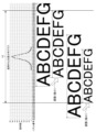
図3には、錠剤数が縦軸に、インクジェットヘッド51のノズル番号が横軸にされ、錠剤中心が通過する位置(以下、「錠剤中心位置」ともいう。)の分布状態を示すグラフ(錠剤中心位置分布グラフ)が示されている。図3において、インクジェットヘッド51のノズル番号236はインクジェットヘッド51の中心位置である。なお、図3のグラフは6000個の錠剤Tを錠剤印刷装置1に投入したときの結果を示したものである。
In FIG. 3, the number of tablets is plotted on the vertical axis, and the nozzle number of the
例えば、錠剤中心位置がノズル番号220~247の範囲で変化すると、錠剤数も変化しており、このグラフ中、錠剤中心位置がノズル番号236の直下を通過する錠剤数は800錠を超えて最大となっている。つまり、15パーセント近くの錠剤は、その中心がインクジェットヘッド51の中心に位置するノズル51aであるノズル番号236の直下となるように搬送されている。さらに、ノズル番号236の隣に位置するノズル番号235、237、さらにその隣のノズル番号234、238に錠剤Tの中心がくるように搬送されるものまで含めると、約3500個の錠剤Tは、その中心がこれらのノズル番号234~238の直下にくるように搬送されていることが分かる。すなわち、全体の58%を超える錠剤Tは、その中心がこれら5つのノズル番号234~238のいずれかの直下にくるように搬送される。これに対し、錠剤中心位置がノズル番号220~223の直下を通過する錠剤数は数錠であり、ノズル番号246~247の直下を通過する錠剤数も数錠である。
For example, when the tablet center position changes in the range of nozzle numbers 220 to 247, the number of tablets also changes, and in this graph, the number of tablets where the tablet center position passes directly under nozzle number 236 exceeds 800 tablets and reaches a maximum. It becomes. In other words, nearly 15% of the tablets are transported such that their centers are directly below nozzle number 236, which is the
錠剤中心位置は、図3において、錠剤数が最大となるノズル番号236を中心として左側に16(=236-220)ノズル分ずれたり、右側に11(=247-236)ノズル分ずれたりするため、合計で27(=247-220)ノズル分変動する。一例として、ノズル間隔が0.04mmであれば(以下も同様)、錠剤中心位置は、27×0.04=1.08mm、つまり約1mmの範囲内で変動する。 In FIG. 3, the tablet center position is shifted to the left by 16 (=236-220) nozzles or to the right by 11 (=247-236) nozzles from nozzle number 236, where the number of tablets is maximum. , it fluctuates by a total of 27 (=247-220) nozzles. As an example, if the nozzle spacing is 0.04 mm (the same applies below), the tablet center position varies within a range of 27 x 0.04 = 1.08 mm, that is, about 1 mm.
図3では、印刷パターンが一例として「ABCDEFG」であり、その印刷パターンのY方向(図2参照)の幅が4mmである場合、前述した通り、使用するノズル数は4/0.04+1=101個となり、錠剤中心位置がノズル番号236である場合、使用ノズル範囲はノズル番号186~286となる。また、錠剤中心位置がノズル番号247である場合、使用ノズル範囲はノズル番号197~297となり、錠剤中心位置がノズル番号220である場合、使用ノズル範囲はノズル番号170~270となる。このように、図3によれば、使用ノズル範囲はノズル番号170~297の範囲内でシフトするため、(297-170)×0.04=5.08mm、つまり約5mmの範囲内で変化することになる。
In FIG. 3, the print pattern is "ABCDEFG" as an example, and if the width of the print pattern in the Y direction (see FIG. 2) is 4 mm, the number of nozzles used is 4/0.04+1=101 as described above. When the tablet center position is nozzle number 236, the nozzle range used is
ここで、一例として、錠剤中心位置がノズル番号230~242の範囲内であれば、不良品発生率が所定値(3%などの数%)よりも低く、安定吐出が可能であることが予め実験により判明している。錠剤中心位置がノズル番号230である場合、使用ノズル範囲はノズル番号180~280となり、錠剤中心位置がノズル番号242である場合、使用ノズル範囲はノズル番号192~292となる。この安定吐出が可能である安定吐出範囲H1はノズル番号180~292の範囲となり、(292-180)×0.04=4.48mm、つまり約4.5mmの範囲内である。
Here, as an example, if the tablet center position is within the range of nozzle numbers 230 to 242, it is known in advance that the incidence of defective products is lower than a predetermined value (several percent such as 3%) and stable ejection is possible. This has been confirmed by experiment. When the tablet center position is nozzle number 230, the nozzle range used is
なお、安定吐出範囲H1とは、多数の錠剤Tを順次搬送している状態で、全ノズル51aのうちインクを安定して吐出することが可能なノズル51aの範囲である。この安定吐出範囲H1内に位置するノズル51aが「予め定めた範囲内に位置するノズル」となる。安定吐出範囲H1などの各種情報は、制御部90の記憶部に予め設定されている。
Note that the stable ejection range H1 is a range of the
次に、前述の安定吐出範囲H1に基づく使用ノズル範囲の調整処理の流れについて説明する。 Next, the flow of adjustment processing for the range of nozzles to be used based on the above-mentioned stable ejection range H1 will be explained.
図4に示すように、ステップS1において、撮像部40は、錠剤Tが撮像部40の直下に到達したタイミングで撮像を行い、錠剤Tの上面を含む画像(錠剤位置検出用の画像)を取得して画像処理部80に送信し、画像処理部80が錠剤TのX方向、Y方向及びθ方向の位置を検出する。
As shown in FIG. 4, in step S1, the
ステップS2において、制御部90は、画像処理部80により検出された錠剤TのY方向の位置を把握し、錠剤Tの中心位置の、インクジェットヘッド51の中心位置(基準位置)に対するずれ量を検出する。錠剤TのY方向の位置(位置ズレ量)及び錠剤Tに印刷する印刷パターンに基づき、インクジェットヘッド51の全ノズル51aの中から印刷に使用する使用ノズル範囲を決定する。
In step S2, the control unit 90 grasps the position of the tablet T in the Y direction detected by the
ステップS3において、制御部90は、使用ノズル範囲が安定吐出範囲H1内であるか否かを判断する。これによって、調整前の使用ノズル範囲が安定吐出範囲H1内にすべて収まるか否かが分かる。 In step S3, the control unit 90 determines whether the nozzle range in use is within the stable ejection range H1. This allows it to be determined whether or not the used nozzle range before adjustment is entirely within the stable ejection range H1.
ステップS3において、制御部90が、使用ノズル範囲が安定吐出範囲H1内であると判断すると(YES)、すなわち調整前の使用ノズル範囲が安定吐出範囲H1内に収まっている場合、ステップS4において、印刷パターンなどの情報に基づき、対象の錠剤Tに対して、使用ノズル範囲内のノズル51aによる印刷をインクジェットヘッド51に実行させる(印刷実行)。
In step S3, if the control unit 90 determines that the used nozzle range is within the stable ejection range H1 (YES), that is, if the used nozzle range before adjustment is within the stable ejection range H1, in step S4, Based on information such as the printing pattern, the
一方、ステップS3において、制御部90が、使用ノズル範囲が安定吐出範囲H1内でないと判断すると(NO)、すなわち調整前の使用ノズル範囲が安定吐出範囲H1内に収まっていない場合、ステップS5において、図5に示すように、調整前の使用ノズル範囲が安定吐出範囲H1内からはみ出た量が印刷パターン(使用ノズル範囲)の何%かを検出し、このパーセンテージに応じて使用ノズル範囲が安定吐出範囲H1内に収まるように縮小率を決める。例えば、上記パーセンテージに2をかけた数を100%から引いた数を縮小率として決める(上記パーセンテージが20パーセントである場合、100-(20×2)=60%を縮小率とする。) On the other hand, in step S3, if the control unit 90 determines that the used nozzle range is not within the stable discharge range H1 (NO), that is, if the used nozzle range before adjustment is not within the stable discharge range H1, then in step S5 , as shown in Figure 5, the amount by which the used nozzle range protrudes from the stable ejection range H1 before adjustment is detected as a percentage of the print pattern (used nozzle range), and the used nozzle range is stabilized according to this percentage. The reduction rate is determined so that it falls within the discharge range H1. For example, the reduction rate is determined by subtracting the above percentage multiplied by 2 from 100% (if the above percentage is 20%, the reduction rate is 100-(20×2)=60%).
ステップS6において、制御部90が、縮小率が予め定めた所定値であるパーセンテージ(例えば、50%)以下であるか否かを判断する。 In step S6, the control unit 90 determines whether the reduction ratio is less than or equal to a predetermined value (for example, 50%).
ステップS6において、制御部90が、縮小率が予め定めたパーセンテージより大きいと判断すると(NO)、ステップS7において、前述の縮小率に基づいて印刷に用いるノズル51aを指定し、図5に示すように、印刷後の印刷パターンが縮小されるように使用ノズル範囲を調整する(縮小調整処理)。そして、ステップS4において、対象の錠剤Tに対して調整済の使用ノズル範囲内のノズル51aによる印刷をインクジェットヘッド51に実行させる(印刷実行)。なお、搬送方向A1における縮小は、吐出タイミングによって制御される。
In step S6, if the control unit 90 determines that the reduction rate is larger than a predetermined percentage (NO), in step S7, it specifies the
一方、ステップS6において、制御部90が、縮小率が予め定めたパーセンテージ以下であると判断すると(YES)、ステップS8において、対象の錠剤Tに対するインクジェットヘッド51による印刷を行わないなど、印刷を制限する(印刷制限)。予め定めたパーセンテージは、例えば、印刷パターンが縮小されて錠剤Tに印刷されても、錠剤Tに印刷された印刷パターンが解読困難になったり、その見栄えが悪くなったりしない範囲内で設定されている。
On the other hand, in step S6, if the control unit 90 determines that the reduction rate is less than or equal to a predetermined percentage (YES), in step S8, printing is restricted, such as not printing with the
この使用ノズル範囲の調整方法によれば、図6に示すように、制御部90は、使用ノズル範囲が安定吐出範囲H1内であると、その使用ノズル範囲内のノズル51aによる印刷を実行し、使用ノズル範囲が安定吐出範囲H1内でなければ、使用ノズル範囲を安定吐出範囲H1内に収めるため、印刷後の印刷パターンが縮小されるように使用ノズル範囲を調整する(縮小調整処理)。この調整処理によれば、錠剤Tが錠剤Tの列からY方向へ位置ずれし、その位置ずれ量に基づいて決定した使用ノズル範囲が安定吐出範囲H1から外れた場合に、その錠剤Tに対する印刷が実行される場合には、印刷後の印刷パターンが縮小されるよう使用ノズル範囲の調整を行うことによって使用ノズル範囲が安定吐出範囲H1内となるように調整され、安定吐出範囲H1内のノズル51a、つまり、使用頻度が高いノズル51aが印刷に使用されるので、使用頻度が低いノズル51aが印刷に使用されることを抑えることができる。これにより、常に使用頻度が高いノズル51aを用いて印刷を行うことが可能となるので、ノズル51aから吐出されたインクが曲がったり、インク量が不十分となって印字がかすれたりせず、安定した印刷を実現し、不良錠剤を減らして生産性を上げることができる。
According to this method of adjusting the usable nozzle range, as shown in FIG. 6, when the usable nozzle range is within the stable ejection range H1, the control unit 90 executes printing with the
(印刷工程)
次に、前述の錠剤印刷装置1が行う印刷工程(検査工程も含む)について説明する。なお、印刷に要する印刷データなどの各種情報は、制御部90の記憶部に予め記憶されている。
(Printing process)
Next, the printing process (including the inspection process) performed by the above-mentioned
まず、搬送ベルト21が駆動され、その搬送ベルト21は、モータ24による駆動プーリ22及び従動プーリ23の回転に伴い、搬送方向A1に回転する。そして、搬送ベルト21が回転している状態で、ホッパ11から錠剤Tがシュータ12に順次供給され、シュータ12により一列に並べられて搬送ベルト21上に一定間隔ではなくランダムに供給される。錠剤Tは搬送ベルト21上に一列に並んで所定の移動速度で搬送されていく。
First, the
搬送ベルト21上の錠剤Tは検出部30によって検出される。これにより、錠剤TのX方向の位置情報が取得され、制御部90に入力される。この錠剤TのX方向の位置情報は、制御部90の記憶部に保存されて後処理で用いられる。次に、搬送ベルト21上の錠剤Tが前述の錠剤TのX方向の位置情報に基づくタイミングで撮像部40によって撮像され、撮像された画像が画像処理部80に送信される。撮像部40から送信された画像に基づき、錠剤Tの位置情報(例えば、X方向、Y方向及びθ方向の位置情報)が画像処理部80により生成され、制御部90の記憶部に保存される。この錠剤Tの位置情報などの情報に基づき、前述の使用ノズル範囲の調整処理が制御部90により実行され、使用ノズル範囲を含む印刷条件(例えば、使用ノズルに基づくインクの吐出位置や吐出速度)が制御部90の記憶部に設定される。
The tablet T on the
使用ノズル範囲の調整処理では、制御部90は、錠剤TのY方向の位置情報に基づき、使用ノズル範囲を決定し、決定した使用ノズル範囲が安定吐出範囲H1内であると、その決定した使用ノズル範囲や印刷パターンなどに基づき印刷条件を設定する。一方、決定した使用ノズル範囲が安定吐出範囲H1内でない場合には、使用ノズル範囲の調整(縮小調整処理)を行うか、インクジェットヘッド51による印刷を制限するかを選択する。使用ノズル範囲の調整を行う場合には、使用ノズル範囲が安定吐出範囲H1内に収まるように印刷後の印刷パターンが縮小されるよう使用ノズル範囲を調整し、調整済の使用ノズル範囲に基づき印刷条件を設定する。また、インクジェットヘッド51による印刷を制限する場合には、対象の錠剤Tに対する印刷を禁止し、未印刷のまま錠剤Tを搬送する。
In the adjustment process of the nozzle range to be used, the control unit 90 determines the nozzle range to be used based on the position information of the tablet T in the Y direction, and if the determined nozzle range to be used is within the stable ejection range H1, the control unit 90 adjusts the nozzle range to be used. Set printing conditions based on nozzle range, print pattern, etc. On the other hand, if the determined nozzle range to be used is not within the stable ejection range H1, it is selected whether to adjust the nozzle range to be used (reduction adjustment process) or to restrict printing by the
搬送ベルト21上の錠剤Tは、前述の画像処理部80が生成した錠剤TのX方向の位置情報に基づくタイミング、すなわち錠剤Tがインクジェットヘッド51の直下に到達したタイミングで、前述の印刷条件に基づいてインクジェットヘッド51により印刷される。インクジェットヘッド51において、各ノズル51aからインクが適宜吐出され、その錠剤Tの上面である被印刷面に文字(例えばアルファベット、片仮名、番号)やマーク(例えば記号、図形)などの識別情報が印刷される。この錠剤Tに塗布されたインクは急速に乾燥する。なお、気体あるいは熱による乾燥を行う乾燥部(図示せず)によりインクを乾燥させるようにしても良い。
The tablets T on the
その後、識別情報が印刷された錠剤Tは、前述の錠剤TのX方向の位置情報に基づくタイミングで撮像部60によって撮像され、撮像された画像が画像処理部80に送信される。撮像部60から送信された個々の画像に基づき、錠剤Tごとの印刷パターンの印刷位置情報、形状情報及びサイズ情報が画像処理部80により生成され、制御部90の記憶部に保存される。その印刷位置情報、形状情報及びサイズ情報に基づき、錠剤Tに対する印刷良否が制御部90により判断され、錠剤Tごとの印刷良否の結果を示す印刷良否結果情報が制御部90の記憶部に保存される。例えば、印刷パターンが所定形状及び所定サイズで錠剤Tの所定位置に印刷されたか否か、すなわち印刷パターンが錠剤Tに正常に印刷されたか否かが判断され、印刷の良否が決定される。
Thereafter, the tablet T with the identification information printed thereon is imaged by the
制御部90は、前述の調整済の使用ノズル範囲に基づいて印刷を実行した錠剤Tに対する印刷検査において、検査用の縮小パターン(例えば、数種の縮小率の印刷パターン)を記憶部に登録しておき、制御部90がその検査用の縮小パターンと実際の印刷後の印刷パターンとを比較して前述の印刷良否の判断を行う。あるいは、予め記憶された検査用パターンを、印刷パターンに係る縮小率に応じて縮小して検査用に用いるようにしても良い。 The control unit 90 registers reduction patterns for inspection (for example, printing patterns with several types of reduction ratios) in the storage unit in the print inspection of the tablet T printed based on the adjusted usage nozzle range described above. Then, the control unit 90 compares the reduced pattern for inspection with the printed pattern after actual printing to determine whether the printing is good or bad. Alternatively, a pre-stored inspection pattern may be reduced in accordance with the reduction ratio of the print pattern and used for inspection.
検査後の錠剤Tは、搬送ベルト21の移動に伴って搬送ベルト21の下流側の端部に位置すると、搬送ベルト21に保持された状態から解放され、搬送ベルト21から落下して回収部70により回収される。このとき、検査が合格であった錠剤Tは、そのまま落下して回収部70により回収されるが、検査が不合格であった錠剤Tは、搬送ベルト21から落下する途中でエアの吹き付けにより排除される。なお、エアの吹き付けにより排除された錠剤Tは、例えば、回収部70の隣に設けられた他の回収容器(図示せず)によって回収される。
When the inspected tablet T is located at the downstream end of the
この印刷工程によれば、使用ノズル範囲は前述の使用ノズル範囲の調整方法によって調整、決定される。使用ノズル範囲が安定吐出範囲H1内である場合には、使用ノズル範囲が変更されずにそのまま印刷に用いられ、使用ノズル範囲が安定吐出範囲H1内でない場合には、使用ノズル範囲が安定吐出範囲H1に収めるべく、印刷後の印刷パターンが縮小されるように使用ノズル範囲が調整され(縮小調整処理)、調整済の使用ノズル範囲内のノズル51aが印刷に用いられる。これにより、常に、安定吐出範囲H1内のノズル51a、すなわち使用頻度が高いノズル51aを用いて印刷を行うことが可能となるので、不良錠剤を減らし、生産性を上げることができる。
According to this printing process, the usable nozzle range is adjusted and determined by the above-described method of adjusting the usable nozzle range. If the used nozzle range is within the stable ejection range H1, the used nozzle range is used for printing as is without being changed, and if the used nozzle range is not within the stable ejection range H1, the used nozzle range is within the stable ejection range. In order to fit within H1, the nozzle range in use is adjusted so that the print pattern after printing is reduced (reduction adjustment process), and the
また、印刷前の印刷パターン(例えば、これから印刷しようとする文字)を縮小するのではなく、印刷後の印刷パターン(例えば、実際に印刷された文字)が縮小されるように使用ノズル範囲が調整されるので、印刷パターンの縮小処理に比べ、処理時間を短縮することができる。 In addition, the nozzle range used is adjusted so that the print pattern after printing (for example, the characters that were actually printed) is reduced, rather than the print pattern before printing (for example, the characters that are about to be printed). Therefore, the processing time can be reduced compared to printing pattern reduction processing.
なお、錠剤Tの位置ずれ量が大きいために、例えば縮小調整処理前の使用ノズルの半分以上が安定吐出範囲H1を超えるような場合には、印刷パターンが縮小されることによって識別情報が解読困難になったり、見栄えが悪くなったりすることもある。このため、検出された錠剤Tの位置ずれ量が予め定めた所定の範囲内でない場合には、対象の錠剤Tに対する印刷が制限され、未印刷のまま錠剤Tが搬送されるようにしても良い。あるいは、錠剤Tの位置ずれ量に基づき決定された使用ノズル範囲のうち、一部が安定吐出範囲H1内からはみ出ている場合で、そのはみ出た量が予め定めた所定値以上である場合、例えば、使用ノズル範囲に対するはみ出し量の割合(パーセンテージ)が予め定めた所定値であるパーセンテージ以上になる場合には、対象の錠剤Tに対する印刷を禁止するようにしても良い。 In addition, if the amount of positional deviation of the tablet T is large, for example, if more than half of the nozzles used before the reduction adjustment process exceed the stable ejection range H1, the printed pattern will be reduced and the identification information will be difficult to decipher. It may also cause the appearance to deteriorate. Therefore, if the detected amount of positional deviation of the tablet T is not within a predetermined range, printing on the target tablet T may be restricted and the tablet T may be transported without being printed. . Alternatively, if a part of the usage nozzle range determined based on the amount of positional deviation of the tablet T protrudes from within the stable ejection range H1, and the amount of protrusion is greater than a predetermined value, for example, If the ratio (percentage) of the amount of protrusion to the nozzle range used exceeds a predetermined value, printing on the target tablet T may be prohibited.
また、上記実施形態においては、錠剤Tの位置ずれ量を求めるためにインクジェットヘッド51の中心位置に対する錠剤Tの中心位置のずれ量を求めたが、これに限るものではない。例えば、撮像部40の視野中心に対する錠剤Tのずれ量を求めるなど、所定の基準位置からの錠剤Tの位置ずれ量を検出することができればよい。あるいは、使用ノズル範囲が安定吐出範囲H1を外れる錠剤Tの位置ずれ量の閾値を予め求めておき、この閾値と実際の錠剤Tの位置ずれ量との比較を行うことによって縮小調整処理を行うか否かを判定するようにしても良い。
Further, in the above embodiment, in order to obtain the amount of positional deviation of the tablet T, the amount of deviation of the center position of the tablet T with respect to the center position of the
ここで、錠剤Tの搬送時、吸引孔21a上の錠剤Tは、吸引孔21aからの吸引によって搬送ベルト21に保持されるが、全ての吸引孔21aが錠剤Tによって完全に塞がれるわけではない。この場合、空気が吸引孔21aから吸引されるため、吸引孔21aの上方には気流が発生し、また、搬送ベルト21の移動によって搬送方向A1に沿って搬送ベルト21上を流れる気流も発生する。さらに、インクジェットヘッド51やその周辺の部材が搬送ベルト21上方に存在するため、搬送ベルト21上を流れる気流がそれらの部材にぶつかってさらに乱気流も発生する。これらの気流が発生するため、インクジェットヘッド51はノズル先端部分のインク乾燥が進行しやすい環境に存在している。このような状況下において、不良錠剤の発生を抑え、生産性を上げるためには、ノズル先端部分のインク乾燥が進行し難い安定吐出範囲H1内のノズル51a、すなわち使用頻度が高いノズル51aを使用することが重要となる。なお、前述の乾燥部がインクジェットヘッド51の下流側に位置付けられて搬送ベルト21の上方に設けられることがある。この場合には、ノズル先端部分のインク乾燥がさらに進行しやすくなる。
Here, when the tablet T is conveyed, the tablet T on the
以上説明したように、第1の実施形態によれば、使用ノズル範囲が安定吐出範囲H1内でないと判断した場合、使用ノズル範囲を安定吐出範囲H1内に収めるべく、印刷後の印刷パターンが縮小されるように使用ノズル範囲を調整し、調整した使用ノズル範囲内のノズル51aによる印刷をインクジェットヘッド51に実行させることによって、安定吐出範囲H1内のノズル51aによる印刷を実現することができる。これにより、安定吐出範囲H1内のノズル51a、すなわち使用頻度が高いノズル51aを使用し、安定吐出範囲H1外のノズル51a、すなわち使用頻度が低いノズル51aの使用を抑えることが可能になるので、不良錠剤の発生を抑え、生産性を上げることができる。
As explained above, according to the first embodiment, when it is determined that the used nozzle range is not within the stable ejection range H1, the printed pattern after printing is reduced in order to keep the used nozzle range within the stable ejection range H1. By adjusting the usable nozzle range so that the
<第2の実施形態>
第2の実施形態について図7から図9を参照して説明する。第2の実施形態では、第1の実施形態との相違点(シフト調整処理)について説明し、その他の説明は省略する。
<Second embodiment>
A second embodiment will be described with reference to FIGS. 7 to 9. In the second embodiment, differences from the first embodiment (shift adjustment processing) will be explained, and other explanations will be omitted.
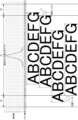
第2の実施形態では、制御部90は、第1の実施形態に係る縮小調整処理にかえて、使用ノズル範囲をシフトさせるシフト調整処理を実行する。例えば、制御部90は、図7及び図8に示すように、使用ノズル範囲が安定吐出範囲H1内に収まらなければ、使用ノズル範囲をインクジェットヘッド51の中心側(図7では、ノズル番号236側)にずらして、使用ノズル範囲が安定吐出範囲H1内に収まるように調整する(シフト調整処理)。なお、図8に示すように、使用ノズル範囲が安定吐出範囲H1内に収まる場合には、その使用ノズル範囲内のノズル51aによる印刷を実行する(図8中の最上の錠剤T参照)。
In the second embodiment, the control unit 90 executes a shift adjustment process for shifting the nozzle range to be used, instead of the reduction adjustment process according to the first embodiment. For example, as shown in FIGS. 7 and 8, if the used nozzle range does not fall within the stable ejection range H1, the control unit 90 changes the used nozzle range to the center side of the inkjet head 51 (in FIG. 7, to the nozzle number 236 side). ) so that the nozzle range in use falls within the stable ejection range H1 (shift adjustment process). As shown in FIG. 8, when the nozzle range in use falls within the stable ejection range H1, printing is performed using the
ここで、図7に示す錠剤中心位置分布グラフは、第1の実施形態に係る図3に示す錠剤中心位置分布グラフと同様である。また、図7に示すズレ許容範囲H2は、印刷位置をずらして印刷することが許容される範囲(ズレ許容範囲)であり、安定吐出範囲H1の両側に予め設定される。なお、安定吐出範囲H1、ズレ許容範囲H2などの情報は、制御部90の記憶部に予め設定される。例えば、図7に示すように、ズレ許容範囲H2は、16ノズル分(16×0.04=0.64mm)であり、安定吐出範囲H1の両側に存在する。安定吐出範囲H1の左側のズレ許容範囲H2はノズル番号164~180であり、安定吐出範囲H1の右側のズレ許容範囲H2はノズル番号292~308である。 Here, the tablet center position distribution graph shown in FIG. 7 is similar to the tablet center position distribution graph shown in FIG. 3 according to the first embodiment. Further, a shift tolerance range H2 shown in FIG. 7 is a range (shift tolerance range) in which printing with a shifted printing position is permitted, and is set in advance on both sides of the stable ejection range H1. Note that information such as the stable ejection range H1 and the deviation tolerance range H2 is set in advance in the storage unit of the control unit 90. For example, as shown in FIG. 7, the deviation tolerance range H2 is for 16 nozzles (16×0.04=0.64 mm), and exists on both sides of the stable ejection range H1. The allowable deviation range H2 on the left side of the stable ejection range H1 is nozzle numbers 164-180, and the allowable deviation range H2 on the right side of the stable ejection range H1 is nozzle numbers 292-308.
次に、安定吐出範囲H1及びズレ許容範囲H2に基づく使用ノズル範囲の調整処理の流れについて説明する。 Next, the flow of adjustment processing for the nozzle range to be used based on the stable ejection range H1 and the deviation tolerance range H2 will be described.
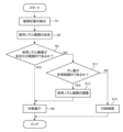
図9に示すように、ステップS11、S12、S13以外のステップS1~S4の処理の流れは、第1の実施形態に係る図4に示すステップS1~S4の処理の流れと同様である。このため、以下では、処理の流れが異なるステップS11、S12、S13に関する処理の流れについて説明する。 As shown in FIG. 9, the process flow of steps S1 to S4 other than steps S11, S12, and S13 is the same as the process flow of steps S1 to S4 shown in FIG. 4 according to the first embodiment. Therefore, in the following, the processing flow regarding steps S11, S12, and S13, which have different processing flows, will be explained.
ステップS3において、制御部90が、使用ノズル範囲が安定吐出範囲H1内でないと判断すると(NO)、ステップS11において、使用ノズル範囲が安定吐出範囲H1から外れたズレ量がズレ許容範囲H2内であるか否かを判断する。 In step S3, if the control unit 90 determines that the used nozzle range is not within the stable ejection range H1 (NO), in step S11, the amount of deviation of the used nozzle range from the stable ejection range H1 is within the deviation tolerance range H2. Determine whether it exists or not.
ステップS11において、制御部90が、ズレ量がズレ許容範囲H2内であると判断すると(YES)、ステップS12において、使用ノズル範囲を安定吐出範囲H1内に収めるようにインクジェットヘッド51の中心側にずらして(なお、ずらした量は「シフト量」と呼ぶことがある。)調整する(シフト調整処理)。そして、ステップS4において、対象の錠剤Tに対して調整済の使用ノズル範囲内のノズル51aによる印刷をインクジェットヘッド51に実行させる(印刷実行)。
In step S11, if the control unit 90 determines that the amount of deviation is within the deviation tolerance range H2 (YES), in step S12, the control unit 90 moves the nozzle toward the center of the
一方、ステップS11において、制御部90が、ズレ量がズレ許容範囲H2内でないと判断すると(NO)、ステップS13において、対象の錠剤Tに対するインクジェットヘッド51による印刷を制限する(印刷制限)。
On the other hand, in step S11, if the control unit 90 determines that the amount of deviation is not within the deviation tolerance range H2 (NO), in step S13, printing by the
この使用ノズル範囲の調整方法によれば、図8に示すように、制御部90は、使用ノズル範囲が安定吐出範囲H1内であると、その使用ノズル範囲内のノズル51aによる印刷を実行し、使用ノズル範囲が安定吐出範囲H1内でなく、使用ノズル範囲のズレ量がズレ許容範囲H2内であると、使用ノズル範囲を安定吐出範囲H1内に収めるように調整、すなわち印刷パターンをY方向に予め決めた量だけシフトさせる。この調整処理によれば、錠剤Tが錠剤Tの列からY方向へずれたことにより、そのずれ量に基づき決定された使用ノズル範囲が安定吐出範囲H1外にずれても、その錠剤Tに対する印刷が実行される場合には、印刷後の印刷パターンが安定吐出範囲H1内となるように使用ノズル範囲の調整を行うことによって、安定吐出範囲H1内のノズル51a、つまり、使用頻度が高いノズル51aが印刷に使用されるので、使用頻度が低いノズル51aが印刷に使用されることを抑えることができる。これにより、常に使用頻度が高いノズル51aを用いて印刷を行うことが可能となるので、ノズル51aから吐出されたインクが曲がったり、インク量が不十分となって印字がかすれたりせず、安定した印刷を実現し、不良錠剤を減らして生産性を上げることができる。
According to this method of adjusting the usable nozzle range, as shown in FIG. 8, when the usable nozzle range is within the stable ejection range H1, the control unit 90 executes printing with the
なお、前述のシフト量は、例えば、使用ノズル範囲が安定吐出範囲H1から外れたズレ量分である。ただし、これはあくまでも一例であり、使用ノズル範囲が安定吐出範囲H1内となるのであれば、使用ノズル範囲が安定吐出範囲H1から外れたズレ量以上であっても良く、また、予め決めた条件に基づいてシフト量を変更して用いるようにしても良い。 Note that the above-mentioned shift amount is, for example, the amount by which the used nozzle range deviates from the stable ejection range H1. However, this is just an example, and as long as the used nozzle range is within the stable discharge range H1, the used nozzle range may deviate from the stable discharge range H1 by more than the deviation amount. The shift amount may be changed and used based on.
以上説明したように、第2の実施形態によれば、使用ノズル範囲が安定吐出範囲H1内でないと判断した場合、使用ノズル範囲を安定吐出範囲H1内に収めるべく、使用ノズル範囲をずらすように調整し、調整した使用ノズル範囲内のノズル51aによる印刷をインクジェットヘッド51に実行させることによって、安定吐出範囲H1内のノズル51aによる印刷を実現することができる。これにより、安定吐出範囲H1内のノズル51a、すなわち使用頻度が高いノズル51aを使用し、安定吐出範囲H1外のノズル51a、すなわち使用頻度が低いノズル51aの使用を抑えることが可能になるので、不良錠剤の発生を抑え、生産性を上げることができる。
As explained above, according to the second embodiment, when it is determined that the nozzle range in use is not within the stable ejection range H1, the nozzle range in use is shifted so as to fall within the stable ejection range H1. By making the adjustment and causing the
<第3の実施形態>
第3の実施形態について図10を参照して説明する。第3の実施形態では、第2の実施形態との相違点(範囲拡大処理)について説明し、その他の説明は省略する。
<Third embodiment>
A third embodiment will be described with reference to FIG. 10. In the third embodiment, differences from the second embodiment (range expansion processing) will be explained, and other explanations will be omitted.
図10は、6000個の錠剤Tを投入した場合に、個々の錠剤Tの位置ずれ量から決定された個々の使用ノズル範囲のうち、Y方向マイナス側の最端ノズル(左端ノズル)を示したグラフである。 FIG. 10 shows the farthest nozzle (leftmost nozzle) on the negative side in the Y direction among the ranges of individual nozzles used determined from the positional deviation amount of each tablet T when 6000 tablets T are input. It is a graph.
図10に示すように、第3の実施形態に係る制御部90は、安定吐出範囲H1を拡大する範囲拡大処理を実行する。この範囲拡大処理では、錠剤Tの位置ずれ量に基づいて決定した各使用ノズル範囲の左端ノズルが、図7に示したズレ許容範囲H2内に複数存在する場合、ズレ許容範囲H2内のノズル51aのうち、予め決めた数、例えば一つだけの特定のノズル51aが安定吐出範囲H1の端となるように安定吐出範囲H1を拡大する(詳しくは後述する)。
As shown in FIG. 10, the control unit 90 according to the third embodiment executes range expansion processing to expand the stable ejection range H1. In this range expansion process, if there are a plurality of left end nozzles in each use nozzle range determined based on the amount of positional deviation of the tablet T within the deviation tolerance range H2 shown in FIG. Among them, the stable ejection range H1 is expanded so that a predetermined number, for example, only one
まず、第2の実施形態に係るシフト調整処理が実行されたことで、ノズル番号180が使用ノズル範囲の左端ノズルとなって印刷に使用された錠剤数は、8ノズル分の集計である96(=2+2+1+4+8+10+18+51)個となる。例えば、図10において、ノズル番号に対応する錠剤数が40~60個以上であれば、安定吐出が可能となる場合、ノズル番号180の錠剤数が51個であるが、この個数をできれば60個以上(投入数の1%程度以上)にすることがより望ましい。このため、安定吐出範囲H1の左端はノズル番号180と設定され、ノズル番号173~179が印刷に使用される場合、そのノズル番号173~179にかえてノズル番号180が印刷に使用される。例えば、ノズル番号173が印刷に使用される場合、そのノズル番号173にかえてノズル番号180が印刷に使用されるが、このときの塗布位置のズレ量(ドットのズレ量)は7ノズル分、例えば7×0.04=0.28mmとなる。
First, by executing the shift adjustment process according to the second embodiment,
そこで、前述の塗布位置のズレ量を抑えるため、第3の実施形態では、錠剤Tの位置ずれ量に基づいて決定した各使用ノズル範囲の左端ノズルが、ズレ許容範囲H2内に複数存在する場合、その使用ノズル範囲の左端がズレ許容範囲H2内で予め決めた特定のノズル51aにくるように使用ノズル範囲をシフトさせる。ノズル番号に対応する錠剤数が40~60個以上であれば、安定吐出が可能となる場合、ノズル番号に対応する錠剤数が少なくとも40個以上であれば、安定吐出が可能となる。このため、決定された使用ノズル範囲の左端ノズルがずれ許容範囲H2に位置する場合、その左端ノズルが、図10に示すように、安定吐出範囲H1の左端のノズル番号180から、予め決めた間隔を開けた、例えばノズル番号178となるように使用ノズル範囲をシフトさせる。つまり、安定吐出範囲H1を拡大し、拡大された安定吐出範囲H1内のノズル51aを用いて錠剤Tの印刷が行われることになる。図10に示す場合、決定された使用ノズル範囲の左端ノズルがノズル番号173~179となる場合、ノズル番号178が使用ノズル範囲の左端ノズルとなるように使用ノズル範囲をシフトさせる。これにより、ノズル番号178のノズルが左端ノズルとして使用されて印刷される錠剤数は、7ノズル分の集計である45(=2+2+1+4+8+10+18)個となる。安定吐出範囲H1内であるノズル番号180の錠剤数は、51個であるため、ノズル番号180の安定吐出を損なうこともない。
Therefore, in order to suppress the above-mentioned amount of deviation in the application position, in the third embodiment, when there is a plurality of left end nozzles of each use nozzle range determined based on the amount of positional deviation of the tablet T within the deviation tolerance range H2. , the nozzle range to be used is shifted so that the left end of the nozzle range to be used is located at a predetermined
前述のように、第2の実施形態によれば、ノズル番号173にかえてノズル番号180が印刷に使用されると、塗布位置のズレ量は7ノズル分(例えば0.28mm)となるが、第3の実施形態によれば、ノズル番号173にかえて特定のノズル番号178が印刷に強制的に使用されると、塗布位置のズレ量は5ノズル分(例えば0.20mm)となる。他のノズル番号でも同様に、第3の実施形態では、第2の実施形態に比べて塗布位置のズレ量が少なくなる。このように、塗布位置のズレ量を抑えることができる。ただし、錠剤Tのサイズや印刷パターンなどによって塗布位置のズレ量が問題となる量(例えば、錠剤Tに印刷された印刷パターンが解読困難になったり、その見栄えが悪くなったりする量)は異なるため、塗布位置のズレ量が問題となる量でなければ、前述の範囲拡大処理を実行しなくても良い。
As described above, according to the second embodiment, when
なお、使用ノズル範囲の左端ノズルがノズル番号178となるように使用ノズル範囲をシフトさせるのにかえて、使用ノズル範囲の左端ノズルがノズル番号173~177、179のいずれか一つだけとなるように使用ノズル範囲をシフトさせることも可能である。また、一つだけのノズル51aではなく、予め決めた数だけのノズル51a(ノズル番号)を選択し、使用ノズル範囲の左端ノズルが、選択した複数のノズル番号のいずれかとなるように使用ノズル範囲をシフトさせるようにしても良い。このとき、一定間隔で並ぶ所定数のノズル51aを選択するようにしても良く、また、ランダムで並ぶ所定数のノズル51aを選択するようにしても良い。
In addition, instead of shifting the used nozzle range so that the leftmost nozzle in the used nozzle range becomes
以上説明したように、第3の実施形態によれば、第2の実施形態に係る効果を得ることができる。さらに、第3の実施形態によれば、使用ノズル範囲を調整する場合、第2の実施形態で説明した安定吐出範囲H1を拡大し、拡大した安定吐出範囲H1内のノズル51aのみを使用して錠剤Tに対する印刷を行うべく、使用ノズル範囲を調整することによって、塗布位置のズレ量を抑えることができ、また、安定吐出範囲H1内のノズル51aによる印刷を実現することができる。その結果、不良錠剤の発生を抑え、生産性を上げることができる。なお、第3の実施形態として、Y方向マイナス側の安定吐出範囲を拡大する例を説明したが、Y方向プラス側のノズル(右端ノズル)の安定吐出範囲も同様に拡大処理を行う。
As explained above, according to the third embodiment, the effects of the second embodiment can be obtained. Furthermore, according to the third embodiment, when adjusting the nozzle range to be used, the stable discharge range H1 explained in the second embodiment is expanded, and only the
<他の実施形態>
前述の説明においては、縮小調整処理及びシフト調整処理のどちらか一方を実行することを例示したが、これに限るものではなく、縮小調整処理及びシフト調整処理の両方を実行するようにしても良い。例えば、使用ノズル範囲の調整処理では、図11に示すように、印刷後の印刷パターンが縮小されるように使用ノズル範囲を調整する縮小調整処理を行うことに加え、印刷後の印刷パターンがY方向にシフトされるように使用ノズル範囲を調整するシフト調整処理を行う(図11中の矢印参照)。一例として、制御部90は、錠剤Tの位置ずれ量に基づいて使用ノズル範囲が安定吐出範囲H1内に収まるように縮小率を求めたところ、求めた縮小率が予め定めたパーセンテージ(例えば、50%)以下になる場合には、求めた縮小率を予め定めたパーセンテージより大きくしたうえで、インクジェットヘッド51の中心側に使用ノズル範囲をシフトさせる。これにより、錠剤Tの位置ずれ量が大きい場合であっても、識別情報が解読困難になったり、見栄えが悪くなったりすることがないように印刷を行うことが可能になるので、不良錠剤をより確実に減らして生産性を上げることができる。
<Other embodiments>
In the above description, an example was given in which either the reduction adjustment process or the shift adjustment process is executed, but the present invention is not limited to this, and both the reduction adjustment process and the shift adjustment process may be executed. . For example, in the process of adjusting the range of nozzles used, as shown in FIG. Shift adjustment processing is performed to adjust the nozzle range to be used so that it is shifted in the direction (see the arrow in FIG. 11). As an example, when the control unit 90 calculates a reduction rate based on the amount of positional deviation of the tablet T so that the nozzle range in use falls within the stable ejection range H1, the control unit 90 determines that the calculated reduction rate is a predetermined percentage (for example, 50 %), the obtained reduction rate is made larger than a predetermined percentage, and the nozzle range used is shifted to the center side of the
また、前述の説明においては、縮小調整処理及びシフト調整処理のどちらか一方を実行することや、シフト調整処理及び縮小調整処理の両方を実行することを例示したが、錠剤Tの位置ずれ量に応じて、使用ノズル範囲を安定吐出範囲H1内に入れるよう、縮小調整処理のみを実行するか、シフト調整処理のみを実行するか、縮小調整処理及びシフト調整処理の両方を実行するか、選択するようにしても良い。例えば、錠剤Tの位置ずれ量に基づき、使用ノズル範囲のうちの一部が安定吐出範囲H1内からはみ出た量が予め定めた所定値以上である場合、例えば、使用ノズル範囲に対するはみ出し量の割合(パーセンテージ)が予め定めた所定のパーセンテージ以上になる場合には、シフト調整処理のみを実行したり、あるいは、シフト調整処理及び縮小調整処理の両方を実行したりする。なお、使用ノズル範囲に対するはみ出し量の割合が予め定めた所定のパーセンテージより小さい場合には、縮小調整処理のみを実行する。また、印刷パターンの一文字サイズに応じて、使用ノズル範囲を安定吐出範囲H1内に収めるよう、縮小調整処理のみを実行するか、シフト調整処理のみを実行するか、縮小調整処理及びシフト調整処理の両方を実行するか、選択するようにしても良い。例えば、制御部90は、錠剤Tの印刷パターン中の一文字のサイズに応じ、縮小調整処理を実行すると、印刷パターンに係る縮小率が解読困難である所定のパーセンテージ以下であると判断した場合、シフト調整処理のみを実行したり、あるいは、シフト調整処理及び縮小調整処理の両方を実行したりする。 In addition, in the above explanation, execution of either the reduction adjustment process or the shift adjustment process or the execution of both the shift adjustment process and the reduction adjustment process was exemplified, but the amount of positional deviation of the tablet T Accordingly, select whether to execute only the reduction adjustment process, only the shift adjustment process, or both the reduction adjustment process and the shift adjustment process so that the nozzle range to be used is within the stable ejection range H1. You can do it like this. For example, if the amount by which part of the used nozzle range protrudes from within the stable ejection range H1 is greater than a predetermined value based on the amount of positional deviation of the tablet T, for example, the ratio of the protruded amount to the used nozzle range If (percentage) is equal to or greater than a predetermined percentage, only the shift adjustment process or both the shift adjustment process and the reduction adjustment process are executed. Note that if the ratio of the protrusion amount to the used nozzle range is smaller than a predetermined percentage, only the reduction adjustment process is executed. Also, depending on the character size of the print pattern, in order to keep the used nozzle range within the stable ejection range H1, it is possible to execute only the reduction adjustment process, only the shift adjustment process, or perform both the reduction adjustment process and the shift adjustment process. You may perform both or select one. For example, when the control unit 90 executes the reduction adjustment process according to the size of one character in the print pattern of the tablet T, if the control unit 90 determines that the reduction rate of the print pattern is less than a predetermined percentage that is difficult to decipher, the control unit 90 shifts Only the adjustment process is executed, or both the shift adjustment process and the reduction adjustment process are executed.
また、前述の説明においては、縮小調整処理で印刷パターンの全体を均等に縮小することを例示したが、これに限るものではなく、例えば、印刷パターンをY方向(水平面内において搬送方向A1と直交する方向)にだけ縮小しても良く、また、印刷パターンの一部だけを縮小又は変形するようにしても良い。例えば、印刷パターンが「ABCDEF」である場合には、それらの文字のうち一つ又は複数の文字だけを縮小又は変形することが可能である。また、一文字の全体を縮小又は変形するのではなく、一文字の一部だけを縮小又は変形することも可能である。なお、一文字を縮小する場合には、一文字の全体を均等に縮小しても良く、また、一文字をY方向にだけ縮小しても良い。 In addition, in the above description, the reduction adjustment process illustrated that the entire print pattern is reduced uniformly, but the invention is not limited to this. For example, the print pattern is It is also possible to reduce or transform only a part of the printed pattern. For example, if the print pattern is "ABCDEF", it is possible to reduce or transform only one or more of the characters. Furthermore, instead of reducing or transforming the entire character, it is also possible to reduce or transform only a part of the character. Note that when reducing one character, the entire character may be reduced equally, or one character may be reduced only in the Y direction.
また、前述の説明においては、縮小調整処理において、調整前の使用ノズル範囲が安定吐出範囲H1からはみ出た量が印刷パターン(使用ノズル範囲)の何%かを検出し、このパーセンテージに応じて使用ノズル範囲が安定吐出範囲H1内に収まるように縮小率を決めることを例示したが、これに限るものではなく、前記はみ出た量に応じて、予め登録された段階的な縮小率(例えば5パーセントごと)のパターンから選択し、選択されたパターンを印刷するようにしてもよい。 In addition, in the above explanation, in the reduction adjustment process, the amount by which the used nozzle range protrudes from the stable ejection range H1 before adjustment is detected as a percentage of the print pattern (used nozzle range), and the used nozzle range is determined according to this percentage. Although the example shows that the reduction rate is determined so that the nozzle range falls within the stable ejection range H1, the reduction rate is not limited to this, and a stepwise reduction rate registered in advance (for example, 5% The selected pattern may be printed.
また、前述の説明においては、印刷後に検査を行う場合、検査用の縮小パターンと実際の印刷後の印刷パターンとを比較することを例示したが、これに限るものではなく、検査ハードル自体を下げるようにしても良い。つまり、縮小したパターンも「正常」であると認識するように予め設定しておくようにする。 In addition, in the above explanation, when inspecting after printing, the reduced pattern for inspection is compared with the actual printed pattern after printing, but this is not limited to this, and the inspection hurdle itself is lowered. You can do it like this. In other words, settings are made in advance so that the reduced pattern is also recognized as "normal".
また、前述の説明においては、錠剤Tを一列で搬送することを例示したが、これに限るものではなく、その列数は二列や三列又は四列以上であっても良く、特に限定されるものではなく、搬送ベルト21の本数も二本以上であっても良く、特に限定されるものではない。また、インクジェットヘッド51の個数も二個以上であっても良く、特に限定されるものではない。
Furthermore, in the above explanation, the tablets T are conveyed in one row, but the number of rows is not limited to this, and may be two, three, or four or more, and is not particularly limited. The number of
また、前述の説明においては、インクジェットヘッド51として、ノズル51aが一列に並ぶ印刷ヘッドを例示したが、これに限るものではなく、例えば、ノズル51aが複数列に並ぶ印刷ヘッドを用いるようにしても良い。また、水平面内において搬送方向A1と直交する方向にインクジェットヘッド51を複数並べて用いるようにしても良い。
Further, in the above description, a print head in which the
また、前述の説明においては、インクジェットヘッド51をノズル51aが並ぶ方向が水平面内において搬送方向A1と直交する方向になるように設けることを例示したが、これに限るものではなく、例えば、ノズル51aが並ぶ方向が水平面内において搬送方向A1と交差する方向になるように設けるようにしても良い。
Further, in the above description, the
また、前述の説明においては、錠剤Tの片面を印刷することを例示したが、これに限るものではなく、例えば、搬送部20、検出部30、撮像部40、印刷部50及び撮像部60を一つのユニットし、そのユニットを上下に重ねて配置して、上側の搬送部20で印刷した錠剤Tを反転して下側の搬送部20に受け渡し、錠剤Tの両面を印刷するようにしても良い。
Further, in the above description, printing on one side of the tablet T was exemplified, but the invention is not limited to this. It is also possible to form one unit and arrange the units one above the other, so that the tablet T printed in the
また、前述の説明においては、搬送ベルト21上に錠剤Tを吸引により保持することを例示したが、これに限るものではなく、例えば、搬送ベルト21上に錠剤Tを自重により保持するようにしても良い。あるいは、錠剤Tをポケットに収容して搬送するようにしても良い。ポケットであっても位置ずれは起きる。ポケットの大きさは錠剤Tのサイズより必ず大きいので、ポケット内でずれが発生する。
Further, in the above description, the tablet T is held on the
ここで、前述の錠剤としては、医薬用、飲食用、洗浄用、工業用あるいは芳香用として使用される錠剤を含めることができる。また、錠剤としては、裸錠(素錠)や糖衣錠、フィルムコーティング錠、腸溶錠、ゼラチン被包錠、多層錠、有核錠などがあり、硬カプセルや軟カプセルなど各種のカプセル錠も錠剤に含めることができる。さらに、錠剤の形状としては、円盤形やレンズ形、三角形、楕円形など各種の形状がある。また、印刷対象の錠剤が医薬用や飲食用である場合には、使用するインクとして可食性インクが好適である。この可食性インクとしては、合成色素インク、天然色素インク、染料インク、顔料インクのいずれを使用しても良い。 Here, the above-mentioned tablets can include tablets used for medicine, for eating and drinking, for cleaning, for industrial purposes, and for aromatic purposes. In addition, tablets include plain tablets, sugar-coated tablets, film-coated tablets, enteric-coated tablets, gelatin-encapsulated tablets, multilayer tablets, and dry-coated tablets, as well as various types of capsule tablets such as hard capsules and soft capsules. can be included in Furthermore, tablets can have various shapes such as a disc, a lens, a triangle, and an ellipse. Furthermore, when the tablet to be printed is for pharmaceutical use or food or drink use, edible ink is suitable as the ink to be used. As this edible ink, any of synthetic pigment ink, natural pigment ink, dye ink, and pigment ink may be used.
以上、本発明のいくつかの実施形態を説明したが、これらの実施形態は、例として提示したものであり、発明の範囲を限定することは意図していない。これら新規な実施形態は、その他の様々な形態で実施されることが可能であり、発明の要旨を逸脱しない範囲で、種々の省略、置き換え、変更を行うことができる。これら実施形態やその変形は、発明の範囲や要旨に含まれるとともに、特許請求の範囲に記載された発明とその均等の範囲に含まれる。 Although several embodiments of the present invention have been described above, these embodiments are presented as examples and are not intended to limit the scope of the invention. These novel embodiments can be implemented in various other forms, and various omissions, substitutions, and changes can be made without departing from the gist of the invention. These embodiments and their modifications are included within the scope and gist of the invention, as well as within the scope of the invention described in the claims and its equivalents.
1 錠剤印刷装置
20 搬送部
40 撮像部(検出部の一部)
51 インクジェットヘッド
51a ノズル
80 画像処理部(検出部の一部)
90 制御部
H1 安定吐出範囲
T 錠剤
1
51
90 Control part H1 Stable discharge range T Tablet
Claims (10)
前記搬送部により搬送される前記錠剤の搬送方向とは水平面内において交差する方向の前記錠剤の位置を検出する検出部と、
前記搬送部により搬送される前記錠剤に対し、前記交差する方向に並ぶ複数のノズルからインクを吐出して印刷を行うインクジェットヘッドと、
前記検出部により検出された前記錠剤の位置及び前記錠剤に印刷する印刷パターンに基づき決定された、前記複数のノズルの中で前記錠剤に対する印刷に用いる使用ノズル範囲のうち、その一部が、前記搬送部により順次搬送される前記錠剤に対して、前記複数のノズルのうち前記インクを安定して吐出することが可能な、予め定めた安定吐出範囲内からはみ出た場合に、前記安定吐出範囲内のノズルのみを使用して前記錠剤に対する印刷を行うべく、前記使用ノズル範囲を印刷後の前記印刷パターンが縮小されるように調整、及び/又は、前記使用ノズル範囲をずらすように調整し、調整した前記使用ノズル範囲内のノズルによる印刷を前記インクジェットヘッドに実行させる制御部と、
を備える錠剤印刷装置。 a transport section that transports the tablets;
a detection unit that detects the position of the tablet in a direction that intersects the conveyance direction of the tablet conveyed by the conveyance unit in a horizontal plane;
an inkjet head that prints by ejecting ink from a plurality of nozzles lined up in the intersecting direction on the tablets transported by the transport unit;
Of the range of nozzles used for printing on the tablet among the plurality of nozzles, which is determined based on the position of the tablet detected by the detection unit and the printing pattern to be printed on the tablet, a part thereof is If the tablets that are sequentially conveyed by the conveyance unit are out of a predetermined stable ejection range in which the ink can be stably ejected from among the plurality of nozzles, the ink is within the stable ejection range. Adjusting the nozzle range to be used so that the printing pattern after printing is reduced, and/or adjusting the range of nozzles to be used so as to shift the nozzle range to print on the tablet using only the nozzles of a control unit that causes the inkjet head to perform printing with nozzles within the used nozzle range;
A tablet printing device comprising:
前記搬送部により搬送される前記錠剤の搬送方向とは水平面内において交差する方向の前記錠剤の位置を検出部により検出する工程と、
前記検出部により検出された前記錠剤の位置及び前記錠剤に印刷する印刷パターンに基づき、前記錠剤に印刷を行うインクジェットヘッドが備える、前記交差する方向に並ぶ複数のノズルの中で前記錠剤に対する印刷に用いる使用ノズル範囲を決定し、決定した前記使用ノズル範囲のうちの一部が、前記搬送部により順次搬送される前記錠剤に対して、前記複数のノズルのうちインクを安定して吐出することが可能な、予め定めた安定吐出範囲内からはみ出た場合に、前記安定吐出範囲内のノズルのみを使用して前記錠剤に対する印刷を行うべく、前記使用ノズル範囲を印刷後の前記印刷パターンが縮小されるように調整、及び/又は、前記使用ノズル範囲をずらすように調整し、調整した前記使用ノズル範囲内のノズルによる印刷を前記インクジェットヘッドに実行させる工程と、
を有する錠剤印刷方法。 a step of conveying the tablets by a conveying section;
a step of detecting, by a detection unit, a position of the tablet in a direction that intersects the conveyance direction of the tablet conveyed by the conveyance unit in a horizontal plane;
Based on the position of the tablet detected by the detection unit and the printing pattern to be printed on the tablet, print on the tablet among the plurality of nozzles arranged in the intersecting directions included in the inkjet head that prints on the tablet. A range of nozzles to be used is determined, and a part of the determined nozzle range to be used stably discharges ink from among the plurality of nozzles to the tablets that are sequentially transported by the transport unit. In order to print on the tablet using only the nozzles within the stable ejection range when the tablet exceeds a predetermined stable ejection range in which it is possible to adjusting the inkjet head to be reduced and/or shifting the used nozzle range, and causing the inkjet head to perform printing with nozzles within the adjusted used nozzle range;
A tablet printing method having.
Applications Claiming Priority (2)
| Application Number | Priority Date | Filing Date | Title |
|---|---|---|---|
| JP2019020898 | 2019-02-07 | ||
| JP2019020898 | 2019-02-07 |
Publications (3)
| Publication Number | Publication Date |
|---|---|
| JP2020127721A JP2020127721A (en) | 2020-08-27 |
| JP2020127721A5 JP2020127721A5 (en) | 2023-02-02 |
| JP7424852B2 true JP7424852B2 (en) | 2024-01-30 |
Family
ID=72173888
Family Applications (1)
| Application Number | Title | Priority Date | Filing Date |
|---|---|---|---|
| JP2020017860A Active JP7424852B2 (en) | 2019-02-07 | 2020-02-05 | Tablet printing device and tablet printing method |
Country Status (1)
| Country | Link |
|---|---|
| JP (1) | JP7424852B2 (en) |
Families Citing this family (1)
| Publication number | Priority date | Publication date | Assignee | Title |
|---|---|---|---|---|
| JP7280704B2 (en) | 2019-02-06 | 2023-05-24 | 芝浦メカトロニクス株式会社 | Tablet printing device and tablet printing method |
Citations (4)
| Publication number | Priority date | Publication date | Assignee | Title |
|---|---|---|---|---|
| US20070194034A1 (en) | 2006-02-17 | 2007-08-23 | Vasilios Vasiadis | Device for printing pills, tablets or caplets in a precise manner |
| WO2016084812A1 (en) | 2014-11-29 | 2016-06-02 | 芝浦メカトロニクス株式会社 | Tablet printing device and tablet printing method |
| JP2016198732A (en) | 2015-04-10 | 2016-12-01 | 昭和アルミニウム缶株式会社 | Printer and can body |
| WO2018061852A1 (en) | 2016-09-30 | 2018-04-05 | 芝浦メカトロニクス株式会社 | Tablet-printing apparatus and tablet-printing method |
-
2020
- 2020-02-05 JP JP2020017860A patent/JP7424852B2/en active Active
Patent Citations (5)
| Publication number | Priority date | Publication date | Assignee | Title |
|---|---|---|---|---|
| US20070194034A1 (en) | 2006-02-17 | 2007-08-23 | Vasilios Vasiadis | Device for printing pills, tablets or caplets in a precise manner |
| WO2016084812A1 (en) | 2014-11-29 | 2016-06-02 | 芝浦メカトロニクス株式会社 | Tablet printing device and tablet printing method |
| JP2016198732A (en) | 2015-04-10 | 2016-12-01 | 昭和アルミニウム缶株式会社 | Printer and can body |
| US20180079206A1 (en) | 2015-04-10 | 2018-03-22 | Showa Aluminum Can Corporation | Printing apparatus and can body |
| WO2018061852A1 (en) | 2016-09-30 | 2018-04-05 | 芝浦メカトロニクス株式会社 | Tablet-printing apparatus and tablet-printing method |
Also Published As
| Publication number | Publication date |
|---|---|
| JP2020127721A (en) | 2020-08-27 |
Similar Documents
| Publication | Publication Date | Title |
|---|---|---|
| JP6357351B2 (en) | Tablet printing apparatus and tablet printing method | |
| US10864717B2 (en) | Tablet printing apparatus | |
| JP7284847B2 (en) | tablet printing machine | |
| US10709639B2 (en) | Tablet printing apparatus and tablet printing method | |
| JP7405663B2 (en) | Tablet printing device and tablet printing method | |
| WO2018096860A1 (en) | Transport device, print device, and transport method | |
| WO2018021440A1 (en) | Tablet printing device, tablet, and tablet manufacturing method | |
| JP7424852B2 (en) | Tablet printing device and tablet printing method | |
| TWI684531B (en) | Tablet printing device and tablet printing method | |
| JP7042164B2 (en) | Tablet printing equipment | |
| JP7280704B2 (en) | Tablet printing device and tablet printing method | |
| US10772801B2 (en) | Tablet printing apparatus and tablet printing method | |
| JP6980542B2 (en) | Tablet printing device | |
| US10293597B2 (en) | Tablet printing apparatus | |
| JP7121622B2 (en) | Tablet printing device and tablet printing method | |
| JP7377137B2 (en) | Tablet printing device and tablet printing method | |
| JP6397061B2 (en) | Tablet printing method | |
| CN112839619A (en) | Tablet printing device and tablet printing method | |
| JP7397132B2 (en) | Tablet printing device and tablet printing method | |
| KR20180120592A (en) | Tablet printing apparatus | |
| JP7017659B2 (en) | Tablet printing equipment | |
| KR20210038327A (en) | Tablet printing apparatus and tablet printing method | |
| JP2023014394A (en) | Tablet printing device and tablet printing method | |
| JP2023050476A (en) | Tablet printing device and tablet printing method | |
| WO2018003747A1 (en) | Tablet printing device and tablet printing method |
Legal Events
| Date | Code | Title | Description |
|---|---|---|---|
| RD03 | Notification of appointment of power of attorney |
Free format text: JAPANESE INTERMEDIATE CODE: A7423 Effective date: 20200626 |
|
| A521 | Request for written amendment filed |
Free format text: JAPANESE INTERMEDIATE CODE: A523 Effective date: 20230125 |
|
| A621 | Written request for application examination |
Free format text: JAPANESE INTERMEDIATE CODE: A621 Effective date: 20230125 |
|
| A977 | Report on retrieval |
Free format text: JAPANESE INTERMEDIATE CODE: A971007 Effective date: 20230927 |
|
| A131 | Notification of reasons for refusal |
Free format text: JAPANESE INTERMEDIATE CODE: A131 Effective date: 20231010 |
|
| A521 | Request for written amendment filed |
Free format text: JAPANESE INTERMEDIATE CODE: A523 Effective date: 20231205 |
|
| A131 | Notification of reasons for refusal |
Free format text: JAPANESE INTERMEDIATE CODE: A131 Effective date: 20231219 |
|
| A521 | Request for written amendment filed |
Free format text: JAPANESE INTERMEDIATE CODE: A523 Effective date: 20231226 |
|
| TRDD | Decision of grant or rejection written | ||
| A01 | Written decision to grant a patent or to grant a registration (utility model) |
Free format text: JAPANESE INTERMEDIATE CODE: A01 Effective date: 20240116 |
|
| A61 | First payment of annual fees (during grant procedure) |
Free format text: JAPANESE INTERMEDIATE CODE: A61 Effective date: 20240118 |
|
| R150 | Certificate of patent or registration of utility model |
Ref document number: 7424852 Country of ref document: JP Free format text: JAPANESE INTERMEDIATE CODE: R150 |