JP6810632B2 - Tablet printing device and tablet manufacturing method - Google Patents

Tablet printing device and tablet manufacturing method Download PDF

Info

Publication number
JP6810632B2
JP6810632B2 JP2017025599A JP2017025599A JP6810632B2 JP 6810632 B2 JP6810632 B2 JP 6810632B2 JP 2017025599 A JP2017025599 A JP 2017025599A JP 2017025599 A JP2017025599 A JP 2017025599A JP 6810632 B2 JP6810632 B2 JP 6810632B2
Authority
JP
Japan
Prior art keywords
tablet
determination unit
tablets
printing
defective
Prior art date
Legal status (The legal status is an assumption and is not a legal conclusion. Google has not performed a legal analysis and makes no representation as to the accuracy of the status listed.)
Active
Application number
JP2017025599A
Other languages
Japanese (ja)
Other versions
JP2017144241A5 (en
JP2017144241A (en
Inventor
梓 平野
梓 平野
鶴岡 保次
保次 鶴岡
Current Assignee (The listed assignees may be inaccurate. Google has not performed a legal analysis and makes no representation or warranty as to the accuracy of the list.)
Shibaura Mechatronics Corp
Original Assignee
Shibaura Mechatronics Corp
Priority date (The priority date is an assumption and is not a legal conclusion. Google has not performed a legal analysis and makes no representation as to the accuracy of the date listed.)
Filing date
Publication date
Application filed by Shibaura Mechatronics Corp filed Critical Shibaura Mechatronics Corp
Publication of JP2017144241A publication Critical patent/JP2017144241A/en
Publication of JP2017144241A5 publication Critical patent/JP2017144241A5/ja
Application granted granted Critical
Publication of JP6810632B2 publication Critical patent/JP6810632B2/en
Active legal-status Critical Current
Anticipated expiration legal-status Critical

Links

Images

Description

本発明は、錠剤印刷装置及び錠剤製造方法に関する。 The present invention relates to a tablet printing apparatus and a tablet manufacturing method.

従来、特許文献1に記載された錠剤印刷装置が知られている。この錠剤印刷装置は、搬送ベルトによって、錠剤を順次搬送する。そして、搬送される錠剤の表面に、インクジェットプリンタによって、文字やマーク等を印刷する。 Conventionally, the tablet printing apparatus described in Patent Document 1 is known. This tablet printing device sequentially conveys tablets by a conveying belt. Then, characters, marks, and the like are printed on the surface of the transported tablet by an inkjet printer.

インクジェットプリンタは、複数のノズルを備えたノズルヘッドを有している。ノズルヘッドの複数のノズルからは、印刷データに基づいたパターンに従って、インク滴が吐出され、これにより錠剤に印刷を行う。 An inkjet printer has a nozzle head having a plurality of nozzles. Ink droplets are ejected from a plurality of nozzles of the nozzle head according to a pattern based on print data, thereby printing on tablets.

このようなインクジェットプリンタを用いると、錠剤の品種の切替え等によって、印刷すべき文字やマークが変更されても、提供する印刷データを変えることで即応できる。また、インクジェットプリンタを用いると、錠剤に対して非接触で印刷できる。このため、衛生的であり、印刷対象物の錠剤が飲用である場合に適している。 When such an inkjet printer is used, even if the characters or marks to be printed are changed due to switching of tablet varieties or the like, the print data to be provided can be changed immediately. Further, when an inkjet printer is used, the tablets can be printed without contact. Therefore, it is hygienic and suitable when the tablet to be printed is drinkable.

特開平7−081050号公報Japanese Unexamined Patent Publication No. 7-081050

以上のような印刷装置においては、搬送ベルトにより搬送される錠剤の到来を、錠剤の搬送経路に設けたセンサのON、OFF信号(錠剤の有無信号)の出力によって検出し、印刷や検査など、その後の処理を行っている。ところで、搬送ベルトによって搬送される、隣接する錠剤間に間隔を有している場合には、各錠剤の到来をセンサによって個別に検出できるので、各錠剤に対して印刷等ができ、文字やマークが印刷された錠剤を製造することができる。 In the above-mentioned printing apparatus, the arrival of the tablet transported by the transport belt is detected by the output of the ON / OFF signal (tablet presence / absence signal) of the sensor provided in the tablet transport path, and printing, inspection, etc. Subsequent processing is being performed. By the way, when there is an interval between adjacent tablets transported by a transport belt, the arrival of each tablet can be detected individually by a sensor, so that each tablet can be printed, etc., and characters and marks can be printed. Can be produced as a printed tablet.

しかしながら、何らかの原因で、錠剤が間隔を空けずに互いに接して搬送されてしまう場合がある。このような場合、接して搬送されている錠剤、特に先頭から2個目以降の錠剤を、センサは認識することができない。このため、これらの錠剤に対して、印刷、検査等の処理を正常に行うことができない。 However, for some reason, the tablets may be transported in contact with each other without a gap. In such a case, the sensor cannot recognize the tablets that are transported in contact with each other, particularly the second and subsequent tablets from the beginning. Therefore, it is not possible to normally perform processing such as printing and inspection on these tablets.

本発明の目的は、錠剤が間隔を空けずに搬送されたとしても、錠剤に対して適正な処理を行なうことができる、錠剤印刷装置、錠剤製造方法を提供することにある。 An object of the present invention is to provide a tablet printing apparatus and a tablet manufacturing method capable of appropriately processing a tablet even if the tablets are transported without an interval.

上記の目的を達成するために、本発明の錠剤印刷装置は、錠剤を搬送する搬送装置と、前記搬送装置により搬送される錠剤の表面の高さ位置の変動情報を検出する検出部と、2以上の錠剤が接して搬送されている場合に、前記高さ位置の変動情報に基づいて、各錠剤を識別する錠剤判定部と、前記錠剤判定部により識別された錠剤に対して印刷する印刷部とを有する。 In order to achieve the above object, the tablet printing device of the present invention includes a transport device for transporting tablets, a detection unit for detecting fluctuation information of the surface height position of the tablets transported by the transport device, and two. When the above tablets are in contact with each other and transported, a tablet determination unit that identifies each tablet based on the fluctuation information of the height position and a printing unit that prints on the tablet identified by the tablet determination unit. And have.

前記錠剤判定部により識別された各錠剤についての前記高さ位置の変動情報に基づいて、各錠剤が不良か否かを判定する不良判定部を有し、前記印刷部は、前記不良判定部により不良と判定された錠剤を印刷の対象から除外してもよい。 The printing unit has a defect determination unit that determines whether or not each tablet is defective based on the fluctuation information of the height position of each tablet identified by the tablet determination unit, and the printing unit is determined by the defect determination unit. Tablets determined to be defective may be excluded from printing.

前記高さ位置の変動情報に基づいて、複数の錠剤の重なり合いを判定する重なり判定部を有し、前記不良判定部は、前記重なり判定部による判定結果に応じて、錠剤が不良か否かを判定してもよい。前記重なり判定部は、前記高さ位置の変動情報に基づいて、重なり合った錠剤の上下関係を判定してもよい。 It has an overlap determination unit that determines the overlap of a plurality of tablets based on the fluctuation information of the height position, and the defect determination unit determines whether or not the tablet is defective according to the determination result by the overlap determination unit. You may judge. The overlap determination unit may determine the vertical relationship of the overlapping tablets based on the fluctuation information of the height position.

前記高さ位置の変動情報に基づいて、前記錠剤の傾きを判定する傾き判定部と、前記高さ位置の変動情報に基づいて、錠剤の搬送方向の長さを判定する長さ判定部と、を有し、前記不良判定部は、前記錠剤の傾き及び前記錠剤の搬送方向の長さに基づいて、互いに重なり合っている錠剤が不良か否かを判定してもよい。 An inclination determination unit that determines the inclination of the tablet based on the fluctuation information of the height position, and a length determination unit that determines the length of the tablet in the transport direction based on the fluctuation information of the height position. The defect determination unit may determine whether or not the overlapping tablets are defective based on the inclination of the tablet and the length of the tablet in the transport direction.

前記不良判定部により不良と判定された錠剤を、前記搬送装置から排出する排出装置と、前記排出装置により排出された錠剤を回収する回収装置と、を有してもよい。 It may have a discharge device for discharging tablets determined to be defective by the defect determination unit from the transport device, and a collection device for collecting the tablets discharged by the discharge device.

前記錠剤判定部により識別された錠剤を、印刷前及び印刷後の少なくとも一方で撮像する撮像部を有し、前記不良判定部は、前記撮像部により撮像された画像データに基づいて、錠剤が不良か否かを判定してもよい。 The defect determination unit has an imaging unit that images the tablet identified by the tablet determination unit at least one before and after printing, and the defect determination unit has a defective tablet based on the image data imaged by the imaging unit. It may be determined whether or not.

また、本発明の錠剤製造方法は、錠剤判定部が、搬送装置により2以上の錠剤が接して搬送されている場合に、検出部により検出される錠剤の高さ位置の変動情報に基づいて、各錠剤を識別し、印刷部が、前記錠剤判定部により識別された錠剤に対して印刷する。 Further, in the tablet manufacturing method of the present invention, when two or more tablets are in contact with each other and transported by the tablet determination unit, the tablet determination unit is based on the variation information of the tablet height position detected by the detection unit. Each tablet is identified, and the printing unit prints on the tablet identified by the tablet determination unit.

本発明によれば、錠剤が間隔を空けずに搬送されたとしても、錠剤に対して適正な処理を行なうことができる、錠剤印刷装置、錠剤製造方法を提供することができる。 INDUSTRIAL APPLICABILITY According to the present invention, it is possible to provide a tablet printing apparatus and a tablet manufacturing method capable of appropriately processing a tablet even if the tablets are transported without intervals.

第1の実施形態の錠剤印刷装置の全体構成を模式的に示す図である。It is a figure which shows typically the whole structure of the tablet printing apparatus of 1st Embodiment. 搬送ベルトに載った錠剤を平面方向から見た状態を示す図である。It is a figure which shows the state which the tablet placed on the transport belt is seen from the plane direction. 間隔を空けて搬送される錠剤と、その高さ位置の変動情報を示す説明図である。It is explanatory drawing which shows the tablet which is conveyed at an interval, and the variation information of the height position thereof. 互いに接して搬送される錠剤と、その高さ位置の変動情報を示す説明図である。It is explanatory drawing which shows the tablet which is carried in contact with each other, and the variation information of the height position thereof. 第1の実施形態の錠剤印刷装置における制御装置を示すブロック図である。It is a block diagram which shows the control apparatus in the tablet printing apparatus of 1st Embodiment. トリガ信号が生成されるタイミングを示す説明図である。It is explanatory drawing which shows the timing when a trigger signal is generated. 錠剤印刷手順を示すフローチャートである。It is a flowchart which shows the tablet printing procedure. 錠剤が検出されてから撮像されるまでを示す説明図である。It is explanatory drawing which shows from the detection of a tablet to the image taking. 錠剤が撮像された後、印刷されるまでを示す説明図である。It is explanatory drawing which shows from the image | imaging of the tablet to the printing. 互いに接して搬送されている複数の錠剤が、先頭の錠剤がセンサによって検出されてから撮像される状態を示す説明図である。It is explanatory drawing which shows the state which a plurality of tablets transported in contact with each other are imaged after the first tablet is detected by a sensor. 第2の実施形態の錠剤印刷装置における制御装置を示すブロック図である。It is a block diagram which shows the control apparatus in the tablet printing apparatus of 2nd Embodiment. 互いに接する錠剤に重なりが発生した状態と、その高さ位置の変動情報を示す説明図である。It is explanatory drawing which shows the state which overlap | overlap | occurred the tablet in contact with each other, and the variation information of the height position. 錠剤同士の重なりが大きい態様と、その高さ位置の変動情報を示す説明図である。It is explanatory drawing which shows the mode in which the tablet overlaps greatly, and the variation information of the height position. 第4の実施形態の錠剤印刷装置における制御装置を示すブロック図である。It is a block diagram which shows the control apparatus in the tablet printing apparatus of 4th Embodiment. 重なり合った錠剤の搬送方向の長さと傾きを示す説明図である。It is explanatory drawing which shows the length and inclination of the overlapping tablet in the transport direction. 2つのセンサを設けた態様を示す説明図である。It is explanatory drawing which shows the mode which provided two sensors. 互いに接する錠剤が水平方向にずれている錠剤を示す説明図である。It is explanatory drawing which shows the tablet which is in contact with each other and is shifted in the horizontal direction.

[第1の実施形態]
以下、本発明の第1の実施形態について、図面を用いて説明する。
[構成]
[印刷対象物]
錠剤印刷装置Sは、錠剤Tbを印刷対象物とする。錠剤Tbは、裸錠(素錠)、糖衣錠、フィルムコーティング錠(FC錠)、腸溶錠、ゼラチン被包錠、多層錠、有核錠等の錠剤やタブレットを含む。また、錠剤Tbは、硬カプセル、軟カプセル等のカプセル錠も含む。このような錠剤Tbの用途は、医薬用、食用、洗剤用、工業用等を問わない。なお、本実施形態では、図2及び図3に示されるような、平面視形状が円であり、側面視形状が楕円の錠剤を例にとって説明する。
[錠剤印刷装置]
図1を参照して、実施形態の錠剤印刷装置Sを説明する。錠剤印刷装置Sは、供給装置10、搬送装置20、センサ30、カメラ40、印刷部50、排出装置60、回収装置70、収納装置80、制御装置90を有する。
[供給装置]
供給装置10は、搬送装置20に錠剤Tbを供給する装置である。供給装置10は、ホッパー11、振動フィーダ12、整列フィーダ14、受け渡しフィーダ16を有する。
[First Embodiment]
Hereinafter, the first embodiment of the present invention will be described with reference to the drawings.
[Constitution]
[Print object]
The tablet printing apparatus S uses the tablet Tb as a printing object. Tablets Tb include tablets and tablets such as naked tablets (bare tablets), sugar-coated tablets, film-coated tablets (FC tablets), enteric coated tablets, gelatin-encapsulated tablets, multi-layer tablets, and nucleated tablets. The tablet Tb also includes capsule tablets such as hard capsules and soft capsules. The use of such tablets Tb is not limited to pharmaceutical, edible, detergent, industrial and the like. In this embodiment, a tablet having a circular shape in a plan view and an elliptical shape in a side view as shown in FIGS. 2 and 3 will be described as an example.
[Tablet printing device]
The tablet printing apparatus S of the embodiment will be described with reference to FIG. The tablet printing device S includes a supply device 10, a transfer device 20, a sensor 30, a camera 40, a printing unit 50, a discharge device 60, a collection device 70, a storage device 80, and a control device 90.
[Supply device]
The supply device 10 is a device that supplies the tablet Tb to the transfer device 20. The supply device 10 includes a hopper 11, a vibration feeder 12, an alignment feeder 14, and a delivery feeder 16.

ホッパー11は、錠剤Tbを収容する容器である。振動フィーダ12は、ホッパー11から順次排出される錠剤Tbを、整列フィーダ14に向けて移動させる搬送路である。振動フィーダ12には、図示しない加振器が設けられている。この加振器が振動フィーダ12に加える振動によって、錠剤Tbが移動する。振動フィーダ12は、ホッパー11側の垂直方向の経路と、整列フィーダ14に延びた傾斜した経路を有する。 The hopper 11 is a container for containing the tablet Tb. The vibration feeder 12 is a transport path for moving the tablet Tb sequentially discharged from the hopper 11 toward the alignment feeder 14. The vibration feeder 12 is provided with a vibrator (not shown). The tablet Tb moves due to the vibration applied to the vibration feeder 12 by this vibrator. The vibration feeder 12 has a vertical path on the hopper 11 side and an inclined path extending to the alignment feeder 14.

整列フィーダ14は、振動フィーダ12から錠剤Tbを受け取って、受け渡しフィーダ16に渡す装置である。整列フィーダ14は、図示しない駆動源により回動する2つのプーリに、搬送ベルトが巻き掛けられている。搬送ベルトの搬送路上には、図示しない整列ガイドが設けられている。整列ガイドは、錠剤Tbを、例えば、2列に分けて整列させて、各列の錠剤Tbを受け渡しフィーダ16に向けて順次搬送する。 The alignment feeder 14 is a device that receives the tablet Tb from the vibration feeder 12 and delivers it to the delivery feeder 16. In the alignment feeder 14, a conveyor belt is wound around two pulleys that are rotated by a drive source (not shown). An alignment guide (not shown) is provided on the transport path of the transport belt. The alignment guide arranges the tablets Tb in two rows, for example, and sequentially conveys the tablets Tb in each row toward the feeder 16.

受け渡しフィーダ16は、図示しない2つのプーリに、吸引穴を有する搬送ベルトが巻き掛けられている。搬送ベルトの内側には、図示しない吸引装置に結合した吸引チャンバが設けられている。 In the delivery feeder 16, a transport belt having a suction hole is wound around two pulleys (not shown). Inside the conveyor belt, a suction chamber coupled to a suction device (not shown) is provided.

受け渡しフィーダ16は、整列フィーダ14の後端部の上方と搬送装置20の前端部の上に亘って配置されている。 The delivery feeder 16 is arranged above the rear end of the alignment feeder 14 and above the front end of the transfer device 20.

受け渡しフィーダ16の搬送ベルトは、整列フィーダ14からの錠剤Tbを吸引チャンバの吸引作用によって受け取る。錠剤Tbを受け取った受け渡しフィーダ16の搬送ベルトは、吸引チャンバの吸引作用が働かなくなる位置で、搬送装置20に錠剤Tbを引き渡す。なお、このようにして供給装置10から搬送装置20へ錠剤Tbが引き渡された際、搬送装置20上において、2以上の錠剤Tbが互いに接している状態で搬送される場合がある。
[搬送装置]
搬送装置20は、錠剤Tbを搬送する装置である。搬送装置20は、整列フィーダ14の下流側に配置されている。搬送装置20は、搬送ベルト21、駆動プーリ22、テンションプーリ23、2つの調整プーリ24a、24b、吸引チャンバ25、エンコーダ27を有する。搬送ベルト21は、錠剤Tbを吸着保持して移動することにより、錠剤Tbを搬送するベルトである。搬送ベルト21は、無端状であり、駆動プーリ22、テンションプーリ23、2つの調整プーリ24a、24bに巻き掛けられている。なお、以下の説明では、搬送装置20において、搬送ベルト21が移動することによる搬送方向をDで示す。また、搬送される錠剤Tbが先に通過する位置を上流側、後に通過する位置を下流側とする。無端状の搬送ベルト21の上側と下側で、上流側と下流側とは逆となる。
The transport belt of the delivery feeder 16 receives the tablet Tb from the alignment feeder 14 by the suction action of the suction chamber. The transfer belt of the delivery feeder 16 that has received the tablet Tb delivers the tablet Tb to the transfer device 20 at a position where the suction action of the suction chamber does not work. When the tablets Tb are delivered from the supply device 10 to the transfer device 20 in this way, the tablets Tb may be transported on the transfer device 20 in a state where two or more tablets Tb are in contact with each other.
[Transport device]
The transport device 20 is a device for transporting the tablet Tb. The transfer device 20 is arranged on the downstream side of the alignment feeder 14. The transfer device 20 includes a transfer belt 21, a drive pulley 22, a tension pulley 23, two adjusting pulleys 24a and 24b, a suction chamber 25, and an encoder 27. The transport belt 21 is a belt that transports the tablet Tb by adsorbing and holding the tablet Tb and moving the tablet Tb. The transport belt 21 has an endless shape and is wound around a drive pulley 22, a tension pulley 23, and two adjusting pulleys 24a and 24b. In the following description, in the transport device 20, the transport direction due to the movement of the transport belt 21 is indicated by D. Further, the position where the transferred tablet Tb passes first is the upstream side, and the position where the tablet Tb is passed later is the downstream side. The upper side and the lower side of the endless transport belt 21 are opposite to the upstream side and the downstream side.

搬送ベルト21には、図2に示すように、複数の通孔26が設けられている。複数の通孔26は、搬送ベルト21の移動方向に所定間隔で形成されている。後述するように、この通孔26に吸引力を付与することにより、図中、点線の円で示した錠剤Tbが搬送ベルト21に吸着される。また前述したように、供給装置10から渡される状態によっては、図2の一方の列に示すように、2以上の錠剤Tbが互いに接する状態となり、この状態で搬送ベルト21に吸着されて搬送される。 As shown in FIG. 2, the transport belt 21 is provided with a plurality of through holes 26. The plurality of through holes 26 are formed at predetermined intervals in the moving direction of the transport belt 21. As will be described later, by applying a suction force to the through hole 26, the tablet Tb indicated by the dotted circle in the figure is attracted to the transport belt 21. Further, as described above, depending on the state of being delivered from the supply device 10, as shown in one row of FIG. 2, two or more tablets Tb are in contact with each other, and in this state, they are adsorbed by the transport belt 21 and transported. Ru.

図1に戻り、駆動プーリ22は、モータMによって回転する。駆動プーリ22が回転することにより、搬送ベルト21が駆動される。 Returning to FIG. 1, the drive pulley 22 is rotated by the motor M. The conveyor belt 21 is driven by the rotation of the drive pulley 22.

吸引チャンバ25は、概ね箱状であり、環状の搬送ベルト21の内側に設けられている。吸引チャンバ25には、所定の部位に形成された排気口25aに、図示しない真空ポンプ等の吸気装置が結合されている。 The suction chamber 25 has a substantially box shape and is provided inside the annular transport belt 21. In the suction chamber 25, an intake device such as a vacuum pump (not shown) is coupled to an exhaust port 25a formed at a predetermined portion.

このような吸引チャンバ25により、搬送ベルト21における、駆動プーリ22と調整プーリ24aとの間に位置する通孔26、駆動プーリ22と調整プーリ24bとの間に位置する通孔26、さらに、駆動プーリ22の外周に位置する通孔26のそれぞれに、吸引力が付与される。 With such a suction chamber 25, in the transport belt 21, a through hole 26 located between the drive pulley 22 and the adjustment pulley 24a, a through hole 26 located between the drive pulley 22 and the adjustment pulley 24b, and further drive. A suction force is applied to each of the through holes 26 located on the outer periphery of the pulley 22.

エンコーダ27は、モータMの駆動軸の回転に伴って動作するロータリーエンコーダである。錠剤Tbが、基準となる位置(基準位置)を通過してからのエンコーダーパルスのカウント値を得ることで、その錠剤Tbに関し、基準位置を通過した以降の存在位置を追跡できる。なお、錠剤Tbの位置の特定に用いることができればよいので、エンコーダ27の種類は特定されない。
[センサ]
センサ30は、搬送装置20に搬送される錠剤Tbの高さ位置を検出する検出部である。図1において、搬送ベルト21により搬送される錠剤Tbの高さ位置を検出する位置は、センサ30と対向する、搬送ベルト21上の錠剤検出位置Pdである。センサ30は、例えば、レーザセンサのように、反射型の光学センサを用いることができる。センサ30は、センサ30から検出対象までの距離を検出できる。本実施形態において、センサ30は、センサ30から錠剤Tbの表面(搬送ベルト21に接している面とは反対側の面で、本実施形態では上面)までの距離を検出することで、錠剤Tbの表面の高さ位置を検出する。「センサ30から」とは、「所定の基準位置から」を意味し、センサの距離の演算手法により異なる。例えば、センサ下面を所定の基準位置とすることができるが、これには限定されない。センサ30からの検出値は、後記の錠剤判定部92に逐次出力される。
The encoder 27 is a rotary encoder that operates with the rotation of the drive shaft of the motor M. By obtaining the count value of the encoder pulse after the tablet Tb has passed the reference position (reference position), the existing position of the tablet Tb after passing the reference position can be traced. The type of encoder 27 is not specified as long as it can be used to specify the position of the tablet Tb.
[Sensor]
The sensor 30 is a detection unit that detects the height position of the tablet Tb transported to the transport device 20. In FIG. 1, the position for detecting the height position of the tablet Tb transported by the transport belt 21 is the tablet detection position Pd on the transport belt 21 facing the sensor 30. As the sensor 30, for example, a reflection type optical sensor such as a laser sensor can be used. The sensor 30 can detect the distance from the sensor 30 to the detection target. In the present embodiment, the sensor 30 detects the distance from the sensor 30 to the surface of the tablet Tb (the surface opposite to the surface in contact with the transport belt 21, the upper surface in the present embodiment), thereby detecting the tablet Tb. Detects the height position of the surface of. “From the sensor 30” means “from a predetermined reference position” and differs depending on the calculation method of the distance of the sensor. For example, the lower surface of the sensor can be set as a predetermined reference position, but the present invention is not limited to this. The detected value from the sensor 30 is sequentially output to the tablet determination unit 92 described later.

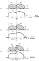
本実施形態でセンサ30は、検出した距離が近いほど大きな値を出力する。そして、搬送される錠剤Tbの高さ位置を、経時的に検出し続けることにより、例えば、図3や図4に示すような、錠剤Tbの高さ位置の変動情報を得ることができる。高さ位置の変動情報は、本実施形態では、高さ位置の変化を示す波形として示す。詳細は後述するが、ちなみに、図3、図4に示す波形において、横軸は時間軸、縦軸はセンサ30の出力値を示している。
[カメラ]
カメラ40は、印刷前の各錠剤Tbを撮像する撮像部である。カメラ40は、印刷部50よりも上流側を搬送される錠剤Tbを撮像して、その撮像信号を画像処理装置41(図5参照)に出力する。画像処理装置41は、カメラ40からの撮像信号を取り込み、錠剤Tbの姿勢を不良判定部95(図5参照)に出力する。錠剤Tbの姿勢とは、搬送ベルト21の上の錠剤Tbの位置ずれ、向き、表裏などの状態である。また、画像処理装置41は、カメラ40から取り込んだ撮像信号を処理して、錠剤Tbの外観の状態を不良判定部95に出力する。外観の状態とは、錠剤の割れ、欠け、あるいは異物、汚れの付着などの外観から分かる錠剤Tbの状態である。カメラ40の視野範囲に入る搬送ベルト21上における領域は、搬送ベルト21の錠剤検出位置Pdと、その下流で印刷を行う印刷位置Ppとの間の所定範囲を含む。
In the present embodiment, the sensor 30 outputs a larger value as the detected distance is shorter. Then, by continuously detecting the height position of the tablet Tb to be transported over time, it is possible to obtain variation information of the height position of the tablet Tb as shown in FIGS. 3 and 4, for example. In the present embodiment, the height position fluctuation information is shown as a waveform indicating the change in the height position. Details will be described later, but by the way, in the waveforms shown in FIGS. 3 and 4, the horizontal axis represents the time axis and the vertical axis represents the output value of the sensor 30.
[camera]
The camera 40 is an imaging unit that images each tablet Tb before printing. The camera 40 takes an image of the tablet Tb conveyed on the upstream side of the printing unit 50, and outputs the image pickup signal to the image processing device 41 (see FIG. 5). The image processing device 41 takes in the image pickup signal from the camera 40 and outputs the posture of the tablet Tb to the defect determination unit 95 (see FIG. 5). The posture of the tablet Tb is a state in which the tablet Tb is displaced, oriented, front and back, etc. on the transport belt 21. Further, the image processing device 41 processes the image pickup signal captured from the camera 40 and outputs the appearance state of the tablet Tb to the defect determination unit 95. The state of appearance is the state of tablet Tb that can be seen from the appearance such as cracking, chipping, foreign matter, and adhesion of dirt. The region on the transport belt 21 that falls within the field of view of the camera 40 includes a predetermined range between the tablet detection position Pd of the transport belt 21 and the print position Pp for printing downstream thereof.

カメラ40の視野範囲は、少なくとも1つの錠剤Tbの全体が撮像できる大きさであればよい。なお、撮像される画像のデータ量を抑えつつ、1つの錠剤Tbの全体を確実に撮像できるようにするため、同時に2つの錠剤Tbの全体が収まるが、3つの錠剤Tbの全体は収まらない大きさとすることが考えられる。このような大きさにすると、1つの錠剤Tbの画像が視野範囲の中心に位置づけられた場合、上流側と下流側で隣接する他の錠剤Tbの画像は、その一部が視野範囲外となる。
[印刷部]
印刷部50は、搬送装置20に搬送される錠剤Tbに印刷を行う機構である。印刷部50は、印刷ヘッド51、印刷確認カメラ52、乾燥ユニット53を有する。本実施形態の場合、印刷ヘッド51は、印刷データに従って、錠剤Tbの表面に印刷を行うインクジェットプリンタのヘッドである。印刷ヘッド51は、圧電素子や熱素子等のエネルギー発生素子を駆動させることにより、インク滴を吐出して印刷を行う複数のノズルを有する。印刷ヘッド51は、カメラ40の下流側の印刷位置Ppにおいて、搬送ベルト21の表面に対向して配置されている。
The field of view of the camera 40 may be large enough to capture the entire image of at least one tablet Tb. In addition, in order to ensure that the entire image of one tablet Tb can be captured while suppressing the amount of data of the image to be captured, the entire two tablets Tb can be accommodated at the same time, but the entire three tablets Tb cannot be accommodated. It is conceivable to make it. With such a size, when the image of one tablet Tb is positioned at the center of the visual field range, a part of the images of other tablet Tb adjacent to each other on the upstream side and the downstream side is out of the visual field range. ..
[Printing section]
The printing unit 50 is a mechanism for printing on the tablet Tb transported to the transport device 20. The printing unit 50 includes a printing head 51, a printing confirmation camera 52, and a drying unit 53. In the case of the present embodiment, the print head 51 is the head of an inkjet printer that prints on the surface of the tablet Tb according to the print data. The print head 51 has a plurality of nozzles for printing by ejecting ink droplets by driving an energy generating element such as a piezoelectric element or a heat element. The print head 51 is arranged so as to face the surface of the transport belt 21 at the print position Pp on the downstream side of the camera 40.

印刷確認カメラ52は、印刷後の錠剤Tbを撮像する撮像部である。印刷確認カメラ52は、印刷ヘッド51を通過した後の錠剤Tbを撮像して、その撮像信号を画像処理装置52aに出力する。画像処理装置52aは、カメラ52からの撮像信号を取り込み、印刷状態を不良判定部95に出力する。印刷確認カメラ52の視野範囲は、錠剤Tbの搬送方向Dにおける印刷位置Ppの下流側の所定範囲に設定されている。 The print confirmation camera 52 is an imaging unit that images the tablet Tb after printing. The print confirmation camera 52 takes an image of the tablet Tb after passing through the print head 51, and outputs the image pickup signal to the image processing device 52a. The image processing device 52a takes in the image pickup signal from the camera 52 and outputs the print state to the defect determination unit 95. The field of view of the print confirmation camera 52 is set to a predetermined range on the downstream side of the print position Pp in the transport direction D of the tablet Tb.

乾燥ユニット53は、搬送ベルト21の下側部分の下方に設けられている。乾燥ユニット53は、搬送ベルト21の駆動プーリ22側に設けられ、錠剤Tbが搬送ベルト21に搬送される際に、表面に印刷された文字やマークのインクを乾燥して定着させる装置である。
[排出装置]
排出装置60は、不良の錠剤Tbを搬送装置20から排出する装置である。排出装置60は、2つのエアー噴射ノズル61、62を有する。エアー噴射ノズル61、62の吹き出し側は、吸引チャンバ25内に、搬送ベルト21を挟んで、回収トレイ71、72に対向する位置に設けられている。排出装置60のエアー噴射ノズル61は、印刷がなされなかったことで不良となる錠剤Tbが、回収トレイ71に対応する位置に来た時に、エアーを噴射して、回収トレイ71に落下させる。エアー噴射ノズル62は、外観不良や印刷不良のために不良となる錠剤Tbが、回収トレイ72に対応する位置に来た時に、エアーを噴射して、回収トレイ72に落下させる。
[回収装置]
回収装置70は、不良の錠剤Tbを回収する装置である。回収装置70は、回収トレイ71、72を有する。回収トレイ71、72は、乾燥ユニット53の下流側に順次配置され、上側が開放された容器である。この回収トレイ71、72は、上記のエアー噴射ノズル61、62に、搬送ベルト21を挟んで対向している。
[収納装置]
収納装置80は、良品の錠剤Tbを収納する装置である。収納装置80は、回収装置70の下流側に、吸引チャンバ25の吸引作用が働かなくなる位置に配置され、上側が開放されたトレイである。
The drying unit 53 is provided below the lower portion of the transport belt 21. The drying unit 53 is provided on the drive pulley 22 side of the transport belt 21, and is a device that dries and fixes the ink of characters and marks printed on the surface when the tablet Tb is transported to the transport belt 21.
[Discharge device]
The discharge device 60 is a device that discharges defective tablets Tb from the transport device 20. The discharge device 60 has two air injection nozzles 61 and 62. The blowout side of the air injection nozzles 61 and 62 is provided in the suction chamber 25 at a position facing the collection trays 71 and 72 with the transport belt 21 interposed therebetween. The air injection nozzle 61 of the discharge device 60 injects air and drops the tablet Tb, which is defective due to non-printing, into the collection tray 71 when the tablet Tb reaches a position corresponding to the collection tray 71. When the tablet Tb, which is defective due to poor appearance or poor printing, comes to a position corresponding to the collection tray 72, the air injection nozzle 62 injects air and drops the tablet Tb onto the collection tray 72.
[Recovery device]
The recovery device 70 is a device for recovering defective tablets Tb. The recovery device 70 has recovery trays 71 and 72. The collection trays 71 and 72 are containers that are sequentially arranged on the downstream side of the drying unit 53 and have an open upper side. The collection trays 71 and 72 face the air injection nozzles 61 and 62 with the transport belt 21 interposed therebetween.
[Storage device]
The storage device 80 is a device for storing non-defective tablets Tb. The storage device 80 is a tray that is arranged on the downstream side of the recovery device 70 at a position where the suction action of the suction chamber 25 does not work, and the upper side is open.

なお、錠剤Tbは、上記のように、整列フィーダ14によって2列に配列される。受け渡しフィーダ16を介して、搬送装置20の搬送ベルト21に供給される。この場合、搬送ベルト21上の2列の錠剤Tbのそれぞれについて印刷を行うために、実際には、上述したセンサ30、カメラ40、印刷ヘッド51、印刷確認カメラ52、乾燥ユニット53、2つのエアー噴射ノズル61、62及び2つの回収トレイ71、72は、当該2列の錠剤Tbに対応するように、2セット設けられている。この2セットは同じ動作を行うので、以下、1セットについて説明する。
[制御装置]
制御装置90は、錠剤印刷装置Sの動作を制御する装置である。制御装置90は、例えば、専用の電子回路若しくは所定のプログラムで動作するコンピュータ等によって実現できる。
The tablets Tb are arranged in two rows by the alignment feeder 14 as described above. It is supplied to the transport belt 21 of the transport device 20 via the delivery feeder 16. In this case, in order to print each of the two rows of tablets Tb on the transport belt 21, the above-mentioned sensor 30, camera 40, print head 51, print confirmation camera 52, drying unit 53, and two airs are actually used. Two sets of the injection nozzles 61 and 62 and the two collection trays 71 and 72 are provided so as to correspond to the two rows of tablets Tb. Since these two sets perform the same operation, one set will be described below.
[Control device]
The control device 90 is a device that controls the operation of the tablet printing device S. The control device 90 can be realized by, for example, a dedicated electronic circuit, a computer operating with a predetermined program, or the like.

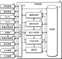
制御装置90の構成を、仮想的な機能ブロック図である図5を参照して説明する。すなわち、制御装置90は、機構制御部91、錠剤判定部92、不良判定部95、追跡部96、記憶部97及び入出力制御部98を有する。 The configuration of the control device 90 will be described with reference to FIG. 5, which is a virtual functional block diagram. That is, the control device 90 includes a mechanism control unit 91, a tablet determination unit 92, a defect determination unit 95, a tracking unit 96, a storage unit 97, and an input / output control unit 98.

機構制御部91は、供給装置10、搬送装置20、印刷部50等の機構部の駆動源、バルブ、スイッチ、電源等を制御する。つまり、機構制御部91によって、供給装置10、搬送装置20の搬送速度、カメラ40の撮像、印刷部50による印刷、排出装置60による不良の錠剤Tbの排出等が制御される。 The mechanism control unit 91 controls a drive source, a valve, a switch, a power supply, and the like of the mechanism unit such as the supply device 10, the transfer device 20, and the printing unit 50. That is, the mechanism control unit 91 controls the transfer speed of the supply device 10 and the transfer device 20, the imaging of the camera 40, the printing by the printing unit 50, the discharge of the defective tablet Tb by the discharge device 60, and the like.

錠剤判定部92は、センサ30の出力信号、つまり錠剤Tbの表面の高さ位置の変動情報に基づいて、搬送装置20により搬送される各錠剤Tbを識別する。上記のように、センサ30からの出力信号を時系列で取得することにより、図3に示すような、高さ位置の変動情報、つまり、高さ位置の変化を示す波形を得ることができる。このような高さ位置の変動情報に基づく錠剤Tbの識別は、例えば、以下のように行う。 The tablet determination unit 92 identifies each tablet Tb transported by the transport device 20 based on the output signal of the sensor 30, that is, the fluctuation information of the height position of the surface of the tablet Tb. By acquiring the output signal from the sensor 30 in time series as described above, it is possible to obtain the height position fluctuation information, that is, the waveform indicating the height position change as shown in FIG. Identification of the tablet Tb based on such height position fluctuation information is performed, for example, as follows.

まず、錠剤判定部92には、2つのしきい値が設定される。第1のしきい値は、図3に示すように、各錠剤Tbが有ることを識別するためのしきい値Hminであり、第2のしきい値は、2以上の錠剤Tbが接して搬送されている場合に、隣接する錠剤Tb間の境界を識別するためのしきい値Hbrdである。一例として、しきい値Hminは、錠剤Tbなし状態から錠剤Tb有り状態への変化を検出するためのものであるから、センサ30の出力値としては低レベル位置に設定される。一方、しきい値Hbrdは、接して搬送される錠剤Tb同士の境界を検出するものであるから、センサ30の出力値のピーク値より低く、かつ、境界からの出力値以上のレベル値に設定される。先に述べた低レベル位置とは、境界からの出力値未満のレベル位置である。なお、この2つのしきい値Hmin、Hbrdは、事前に実験などによって最適値が設定されるようにしても良い。 First, two threshold values are set in the tablet determination unit 92. As shown in FIG. 3, the first threshold value is the threshold value Hmin for identifying the presence of each tablet Tb, and the second threshold value is the contact and transport of two or more tablets Tb. When so, it is a threshold value Hbrd for identifying the boundary between adjacent tablets Tb. As an example, since the threshold value Hmin is for detecting the change from the state without the tablet Tb to the state with the tablet Tb, the output value of the sensor 30 is set to a low level position. On the other hand, since the threshold value Hbrd detects the boundary between the tablets Tb that are transported in contact with each other, the threshold value is set to a level value lower than the peak value of the output value of the sensor 30 and equal to or higher than the output value from the boundary. Will be done. The low level position described above is a level position less than the output value from the boundary. The two threshold values Hmin and Hbrd may be set to optimum values in advance by experiments or the like.

さて、図3に示すように、錠剤Tbが間隔を空けて搬送されている場合、各錠剤Tbに対応して、センサ30の出力値は、錠剤Tbの搬送方向先端を検出した時点から上昇していき、しきい値Hmin、しきい値Hbrdをこの順に超えてピーク値に達し、それ以降は減少に転じ、しきい値Hmin以下となり、錠剤Tbの搬送方向後端が検出領域を抜けると初期レベルに戻る。従って、この場合、センサ30からの出力値としきい値Hbrdとは、各錠剤Tbについて、点aと点bの2点で交差する。 By the way, as shown in FIG. 3, when the tablets Tb are transported at intervals, the output value of the sensor 30 increases from the time when the tip of the tablet Tb in the transport direction is detected corresponding to each tablet Tb. The peak value is reached in this order beyond the threshold value Hmin and the threshold value Hbrd, and thereafter, the value starts to decrease and becomes the threshold value Hmin or less, and the initial stage when the rear end of the tablet Tb in the transport direction passes through the detection region. Return to level. Therefore, in this case, the output value from the sensor 30 and the threshold value Hbrd intersect at two points, point a and point b, for each tablet Tb.

また、図4に示すように、2つの錠剤Tbが互いに接して搬送されている場合、センサ30の出力値は、先頭の錠剤Tbの搬送方向先端を検出した時点から上昇していき、しきい値Hmin、しきい値Hbrdをこの順に超えてピーク値に達し、それ以降は減少に転じ、境界部分にさしかかると一旦、しきい値Hbrdよりも下がってから、しきい値Hminまで下がることなく、再度しきい値Hbrdを超える。その後は、出力値のピークに達した後、減少に転じる。以後は、先に説明した錠剤Tbが1個の場合の搬送方向後端の検出と同様に推移し、しきい値Hmin以下となり、そして初期レベルに戻る。従って、この場合、センサ30からの出力値としきい値Hbrdとは、点a、点b、点c、点dの4点で交差する。もしn(整数)個の錠剤Tbが接して搬送されれば、n×2個の交点が得られることになる。 Further, as shown in FIG. 4, when two tablets Tb are transported in contact with each other, the output value of the sensor 30 increases from the time when the tip of the leading tablet Tb in the transport direction is detected, and the threshold value is increased. The value Hmin and the threshold value Hbrd are exceeded in this order to reach the peak value, and thereafter, the value starts to decrease, and once the boundary portion is approached, once the value falls below the threshold value Hbrd, the value does not drop to the threshold value Hmin. The threshold value Hbrd is exceeded again. After that, after reaching the peak of the output value, it starts to decrease. After that, the transition is the same as the detection of the rear end in the transport direction when the number of tablets Tb is one described above, the threshold value is Hmin or less, and the tablet returns to the initial level. Therefore, in this case, the output value from the sensor 30 and the threshold value Hbrd intersect at four points, point a, point b, point c, and point d. If n (integer) tablets Tb are brought into contact with each other and transported, n × 2 intersections will be obtained.

そこで、本実施形態における錠剤判定部92は、錠剤Tbの移動に伴って変動するセンサ30の出力値と、しきい値Hbrdとの交点が検出されると、順に2個ずつ(点aと点b、点cと点d、…)をペアとして、各ペアの中間位置に対応する搬送方向Dにおける位置を、各錠剤Tbの中心位置として認識(識別)する。 Therefore, when the intersection of the output value of the sensor 30 that fluctuates with the movement of the tablet Tb and the threshold value Hbrd is detected, the tablet determination unit 92 in the present embodiment sequentially has two tablets (points a and points). b, point c and point d, ...) Are paired, and the position in the transport direction D corresponding to the intermediate position of each pair is recognized (identified) as the center position of each tablet Tb.

さらに、高さ位置の変動情報に基づいて各錠剤Tbを識別するとは、高さ位置の変動情報に含まれる各錠剤Tbについての各種の情報を認識することも含む。例えば、各錠剤Tbの長さを認識することも、各錠剤Tbを識別することに含まれる。より具体的な一例としては、本実施形態では、図3、図4に示した点aと点b、点cと点dの各点を求めた後に、a−b間、c−d間に相当する搬送ベルト21上での長さを、錠剤Tbの搬送方向長さLaに対応する値として認識する。 Further, identifying each tablet Tb based on the height position variation information also includes recognizing various information about each tablet Tb included in the height position variation information. For example, recognizing the length of each tablet Tb is also included in identifying each tablet Tb. As a more specific example, in the present embodiment, after the points a and b and the points c and d shown in FIGS. 3 and 4 are obtained, between ab and cd. The length on the corresponding transport belt 21 is recognized as a value corresponding to the transport direction length La of the tablet Tb.

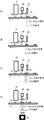
このように、各錠剤Tbを識別した場合、錠剤判定部92は、トリガ信号を生成する。トリガ信号は、その後のカメラ40、印刷確認カメラ52による撮像、印刷ヘッド51を用いた印刷等の処理のタイミングを適切なものとするタイミングで生成される、短いパルス信号で、錠剤Tbの位置情報と一体とされる。このようなトリガ信号の生成を、図6を参照して説明する。図6(A)は間隔を空けて搬送されている2以上の錠剤、図6(B)、(C)は、互いに接して搬送されている2以上の錠剤Tbを、それぞれ模式的に示している。理解を簡単にするために、図6では、4つの錠剤Tbが図中、右から左に向かって搬送される様子を示している。 When each tablet Tb is identified in this way, the tablet determination unit 92 generates a trigger signal. The trigger signal is a short pulse signal generated at a timing that makes the timing of subsequent processing such as imaging by the camera 40 and the print confirmation camera 52 and printing using the print head 51 appropriate, and is position information of the tablet Tb. Is integrated with. The generation of such a trigger signal will be described with reference to FIG. FIG. 6 (A) schematically shows two or more tablets that are transported at intervals, and FIGS. 6 (B) and 6 (C) schematically show two or more tablets Tb that are transported in contact with each other. There is. For ease of understanding, FIG. 6 shows how the four tablets Tb are transported from right to left in the figure.

例えば、図6(A)に示すように、錠剤Tbが間隔を空けて搬送されている場合、錠剤判定部92は、図3を用いて説明した、錠剤Tbごとに得られる交点aとbの中間位置を基準に、トリガ信号を生成する。 For example, as shown in FIG. 6 (A), when the tablets Tb are transported at intervals, the tablet determination unit 92 of the intersection points a and b obtained for each tablet Tb described with reference to FIG. A trigger signal is generated based on the intermediate position.

また、例えば、図6(B)に示すように、2以上の錠剤Tbが接して搬送されている場合、錠剤判定部92は、図4を用いて説明した、交点aとbの中間位置、交点cとdの中間位置、…を基準に、順にトリガ信号(1)、(2)、(3)、(4)…を生成する。 Further, for example, as shown in FIG. 6 (B), when two or more tablets Tb are in contact with each other and transported, the tablet determination unit 92 has an intermediate position between the intersection points a and b described with reference to FIG. Trigger signals (1), (2), (3), (4) ... are generated in order based on the intermediate position between the intersection points c and d.

なお、トリガ信号を生成するに際し、別の態様をここで紹介する。例えば、図6(C)に示すように、2以上の錠剤Tbが接して搬送されている場合、錠剤判定部92は、センサ30の出力信号の立ち上がりを基準に、トリガ信号(1)を生成し、次に、センサ30の出力信号が境界を示す波形となった場合(センサ30の出力のピーク値を過ぎて下降し、しきい値Hminと交差する前に再度上昇に転じる点)を基準に、トリガ信号(2)を生成し、さらに、互いに接している錠剤Tbが連続している場合には、境界を示す波形が到来する度に、トリガ信号(3)、(4)…を生成するようにしても良い。 In addition, another aspect is introduced here in generating a trigger signal. For example, as shown in FIG. 6C, when two or more tablet Tbs are in contact with each other and transported, the tablet determination unit 92 generates a trigger signal (1) based on the rise of the output signal of the sensor 30. Then, the reference is based on the case where the output signal of the sensor 30 has a waveform indicating a boundary (the point where the output signal of the sensor 30 falls past the peak value of the sensor 30 and starts rising again before crossing the threshold value Hmin). In addition, a trigger signal (2) is generated, and when the tablet Tbs in contact with each other are continuous, a trigger signal (3), (4), ... Is generated each time a waveform indicating a boundary arrives. You may try to do it.

なお、図6では、センサ30が錠剤Tbを検出している期間内にトリガ信号の生成タイミングが含まれるように示している。これは、センサ30の出力信号を用いてトリガ信号の生成が行われることを便宜的に図示したに過ぎない。実際のトリガ信号は、センサ30による錠剤Tbの検出以降、その後の処理のタイミングを適切なものとなるタイミングで生成される。つまり、カメラ40による撮像、印刷ヘッド51による印刷、印刷確認カメラ40による撮像などのタイミングをとるために生成される。したがって、トリガ信号は、搬送装置20により搬送される錠剤Tbが、それぞれの処理位置に到達するタイミングになるように生成される。 Note that FIG. 6 shows that the trigger signal generation timing is included within the period during which the sensor 30 is detecting the tablet Tb. This is merely an illustration for convenience that the trigger signal is generated using the output signal of the sensor 30. The actual trigger signal is generated at a timing that makes the timing of the subsequent processing appropriate after the detection of the tablet Tb by the sensor 30. That is, it is generated to take timings such as imaging by the camera 40, printing by the print head 51, and imaging by the print confirmation camera 40. Therefore, the trigger signal is generated so that the tablet Tb transported by the transport device 20 reaches the respective processing positions.

例えば、カメラ40の視野範囲内に錠剤Tbが到達するタイミング、好ましくは、カメラ40の視野範囲の中心に錠剤Tbの中心が来るようなタイミングで、トリガ信号が生成される。具体的には、エンコーダ27の出力値を用いることで、センサ30で検出された個々の錠剤Tbに関し、検出以降の存在位置が追跡できることは前述したとおりである。従って、センサ30の出力値を用いて認識したその錠剤Tbが、カメラ40の視野範囲に位置付けられるタイミング、更には、図3、図4で説明した各錠剤Tbの中心点位置が、カメラ40の視野範囲の中心に位置付けられるタイミングは、エンコーダ27の出力値を用いることで設定することができる。 For example, the trigger signal is generated at the timing when the tablet Tb reaches the field of view of the camera 40, preferably at the timing when the center of the tablet Tb comes to the center of the field of view of the camera 40. Specifically, as described above, by using the output value of the encoder 27, the existence position of each tablet Tb detected by the sensor 30 after the detection can be traced. Therefore, the timing at which the tablet Tb recognized using the output value of the sensor 30 is positioned in the visual field range of the camera 40, and the center point position of each tablet Tb described with reference to FIGS. 3 and 4 are the positions of the camera 40. The timing of positioning at the center of the field of view can be set by using the output value of the encoder 27.

カメラ40は、トリガ信号を基準として撮像を行う。なお、カメラ40による撮像タイミングを例にとって説明したが、印刷ヘッド51による印刷タイミング、印刷確認カメラ40による撮像タイミングも同様である。つまり、センサ30の出力値を用いて認識した錠剤Tbが、エンコーダ27の出力値を頼りに、印刷ヘッド51による印刷位置、印刷確認カメラ40による撮像位置にそれぞれ達したことを検知したタイミングで、トリガ信号が個別に出力される。そして、印刷ヘッド51、印刷確認カメラ40は、それぞれのトリガ信号を基準にして、処理を開始する。 The camera 40 takes an image based on the trigger signal. Although the image pickup timing by the camera 40 has been described as an example, the print timing by the print head 51 and the image capture timing by the print confirmation camera 40 are also the same. That is, at the timing when it is detected that the tablet Tb recognized by using the output value of the sensor 30 reaches the printing position by the print head 51 and the imaging position by the print confirmation camera 40, respectively, depending on the output value of the encoder 27. Trigger signals are output individually. Then, the print head 51 and the print confirmation camera 40 start processing with reference to their respective trigger signals.

不良判定部95は、錠剤Tbが不良か否かを判定する。まず、不良判定部95は、錠剤判定部92により識別された各錠剤Tbについての高さ位置の変動情報に基づいて、各錠剤Tbが不良か否かを判定する。ここで、高さ位置の変動情報には、上述のように、各錠剤Tbの長さ等、各種の情報が含まれる。例えば、不良判定部95は、錠剤判定部92が認識した各錠剤Tbの長さが所定長さ以上であるか否かに基づいて、所定長さよりも短い場合に、不良と判定する。より具体的な一例として、図3に示すa−b間の長さが、1個の錠剤Tbの搬送方向長さLaの1/2以下の場合に、不良と判定する。なお、不良判定部95は、不良と判定された錠剤Tbについて、印刷部50による印刷をさせない処理を行う。つまり、不良と判定された錠剤Tbについては、印刷部50は印刷の対象から除外するため、印刷されない錠剤Tbが発生する。また、不良判定部95は、カメラ40が取り込み、画像処理装置41で処理された処理画像から、汚れ、カケ等の損傷が有る外観不良の錠剤Tbと、位置ずれなどの姿勢状態が、予め設定した基準を超えている錠剤Tbを不良と判定する。さらに、不良判定部95は、印刷確認カメラ52が取り込み、画像処理装置で処理された処理画像から、印刷されなかった錠剤Tb、正常に印刷がなされていない印刷不良の錠剤Tbを、不良と判定する。 The defect determination unit 95 determines whether or not the tablet Tb is defective. First, the defect determination unit 95 determines whether or not each tablet Tb is defective based on the height position variation information of each tablet Tb identified by the tablet determination unit 92. Here, the height position variation information includes various information such as the length of each tablet Tb as described above. For example, the defect determination unit 95 determines that the tablet Tb is defective if it is shorter than the predetermined length based on whether or not the length of each tablet Tb recognized by the tablet determination unit 92 is equal to or greater than the predetermined length. As a more specific example, when the length between a and b shown in FIG. 3 is 1/2 or less of the transport direction length La of one tablet Tb, it is determined to be defective. The defect determination unit 95 performs a process of preventing the printing unit 50 from printing the tablet Tb determined to be defective. That is, since the printing unit 50 excludes the tablet Tb determined to be defective from the printing target, the tablet Tb that is not printed is generated. In addition, the defect determination unit 95 presets the tablet Tb having a poor appearance with damage such as dirt and chips and the posture state such as misalignment from the processed image captured by the camera 40 and processed by the image processing device 41. Tablets Tb that exceed the above criteria are judged to be defective. Further, the defect determination unit 95 determines that the unprinted tablet Tb and the improperly printed tablet Tb are defective from the processed image captured by the print confirmation camera 52 and processed by the image processing device. To do.

追跡部96は、搬送装置20における各錠剤Tbの位置を追跡する。より具体的には、追跡部96は、エンコーダ27によるエンコーダーパルスのカウント値から、移動する各錠剤Tbがどの位置にあるかを特定するもので、すでに述べたとおりである。例えば、追跡部96は、センサ30で検出された錠剤Tbが、カメラ40の視野範囲、印刷部50による印刷及び印刷確認カメラ52の印刷確認位置を含め、最終の収納装置80に到達するまでの追跡を行う。このような追跡部96による追跡は、不良判定部95により不良と判定された錠剤Tbの搬送装置20における位置の追跡を含む。特に、追跡部96は、外観不良や印刷不良と判定された錠剤Tbと、外観不良でなく印刷されなかった錠剤Tbとを、区別して追跡する。 The tracking unit 96 tracks the position of each tablet Tb in the transport device 20. More specifically, the tracking unit 96 identifies the position of each moving tablet Tb from the count value of the encoder pulse by the encoder 27, as described above. For example, in the tracking unit 96, the tablet Tb detected by the sensor 30 reaches the final storage device 80, including the viewing range of the camera 40, the printing by the printing unit 50, and the printing confirmation position of the print confirmation camera 52. Perform tracking. Such tracking by the tracking unit 96 includes tracking the position of the tablet Tb determined to be defective by the defect determination unit 95 in the transport device 20. In particular, the tracking unit 96 distinguishes between the tablet Tb determined to have a poor appearance or a printing defect and the tablet Tb which is not a poor appearance and is not printed.

記憶部97は、錠剤印刷装置Sの処理に必要な各種の情報を記憶する。記憶される情報は、センサ30からの出力信号、トリガ信号の生成タイミング、撮像、印刷等を行うタイミングを決めるエンコーダーパルス数、錠剤Tbを識別するためのしきい値、印刷の可否を判定するためのしきい値、不良の錠剤Tbを判定するためのしきい値等の基準、カメラ40に撮像された画像データ、印刷する文字、マーク等の内容を示す印刷データ、追跡される錠剤Tbの位置等を含む。 The storage unit 97 stores various information necessary for processing of the tablet printing apparatus S. The stored information includes the output signal from the sensor 30, the generation timing of the trigger signal, the number of encoder pulses that determine the timing of imaging, printing, etc., the threshold value for identifying the tablet Tb, and the determination of printability. Criteria, criteria such as thresholds for determining defective tablet Tb, image data captured by the camera 40, print data indicating the contents of characters to be printed, marks, etc., position of the tablet Tb to be tracked. Etc. are included.

入出力制御部98は、制御対象となる各部との間での信号の変換や入出力を制御するインタフェースである。 The input / output control unit 98 is an interface for controlling signal conversion and input / output with each unit to be controlled.

なお、制御装置90には、装置の状態を確認するためのディスプレイ、ランプ、メータ等の出力装置99aが接続されている。センサ30からの出力信号、トリガ信号、カメラ40に撮像された画像データ等を、出力装置99aに表示してもよい。また、制御装置90には、オペレータが、錠剤印刷装置Sの動作に必要な情報を入力するためのスイッチ、タッチパネル、キーボード、マウス等の入力装置99bが接続されている。
[動作]
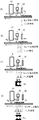
本実施形態の錠剤印刷装置Sにおいて、錠剤Tbの表面に文字やマークを印刷する手順を、図7のフローチャート、図8〜図10の説明図を参照して説明する。なお、図8、図9は、錠剤Tbが間隔を空けて搬送されている場合、図10は、複数の錠剤Tbが接して搬送されている場合を示している。
The control device 90 is connected to an output device 99a such as a display, a lamp, and a meter for checking the state of the device. The output signal from the sensor 30, the trigger signal, the image data captured by the camera 40, and the like may be displayed on the output device 99a. Further, the control device 90 is connected to an input device 99b such as a switch, a touch panel, a keyboard, and a mouse for the operator to input information necessary for the operation of the tablet printing device S.
[motion]
The procedure for printing characters and marks on the surface of the tablet Tb in the tablet printing apparatus S of the present embodiment will be described with reference to the flowchart of FIG. 7 and the explanatory views of FIGS. 8 to 10. 8 and 9 show a case where the tablets Tb are transported at intervals, and FIG. 10 shows a case where a plurality of tablets Tb are in contact with each other and transported.

まず、図7のフローチャートに示すように、供給装置10が、錠剤Tbを搬送装置20に供給する(ステップS101)。つまり、ホッパー11に収容された錠剤Tbは、振動フィーダ12を経由して、整列フィーダ14に渡される。整列フィーダ14は、例えば、2列に配列された錠剤Tbを、受け渡しフィーダ16に渡す。受け渡しフィーダ16は、搬送装置20に、錠剤Tbを渡す。搬送装置20は、図2に示すように、錠剤Tbを、搬送ベルト21に2列で吸着保持された状態で搬送する。 First, as shown in the flowchart of FIG. 7, the supply device 10 supplies the tablet Tb to the transfer device 20 (step S101). That is, the tablet Tb contained in the hopper 11 is passed to the alignment feeder 14 via the vibration feeder 12. The alignment feeder 14 passes, for example, the tablets Tb arranged in two rows to the delivery feeder 16. The delivery feeder 16 delivers the tablet Tb to the transfer device 20. As shown in FIG. 2, the transport device 20 transports the tablets Tb in a state of being sucked and held in two rows on the transport belt 21.

搬送される錠剤Tbは、センサ30によってその高さ位置の変動情報が検出される。そして、錠剤判定部92は、この高さ位置の変動情報に基づき、錠剤Tbごとに、搬送方向D方向における中心位置を認識(識別)し、その認識された中心位置を基準にトリガ信号を生成する(ステップ102)。トリガ信号の生成の詳細は、前述したとおりである。なお、図7のフローチャートは、ステップS102で、全ての錠剤Tbに対するトリガ信号を生成した後、ステップS103以降の処理を行っていることを示しているわけではない。各錠剤Tbについてのトリガ信号の生成が行われているのと同時並行に、先行する錠剤Tbに対する撮像、印刷等の処理が行われている。また、図8(A)〜(C)、図10(A)、(B)は、ステップ102の状態を示している。なお、不良判定部95は、高さ位置の変動情報に基づいて、錠剤Tbが不良か否かを判定し、不良と判定された場合には、印刷部50による印刷の対象から除外される。 The sensor 30 detects the fluctuation information of the height position of the tablet Tb to be transported. Then, the tablet determination unit 92 recognizes (identifies) the center position in the transport direction D direction for each tablet Tb based on the fluctuation information of the height position, and generates a trigger signal based on the recognized center position. (Step 102). The details of the generation of the trigger signal are as described above. It should be noted that the flowchart of FIG. 7 does not indicate that the processing after step S103 is performed after the trigger signals for all the tablets Tb are generated in step S102. Simultaneously with the generation of the trigger signal for each tablet Tb, processing such as imaging and printing of the preceding tablet Tb is performed. 8 (A) to 8 (C), 10 (A), and (B) show the state of step 102. The defect determination unit 95 determines whether or not the tablet Tb is defective based on the height position fluctuation information, and if it is determined to be defective, the defect determination unit 95 is excluded from the printing target by the printing unit 50.

図7のフローチャートに戻り、カメラ40は、図8(D)に示すように、トリガ信号を基準として、各錠剤Tbを撮像するべきタイミングを判定して(ステップS103)、そのタイミングで撮像する(ステップS104)。例えば、図8(D)に示すように、錠剤Tbが移動して、その全体がカメラの視野範囲に入る時点で撮像する。なお、図9(A)〜(C)に示すように、後続の錠剤Tbについても、上記と同様に、センサ30による検出、トリガ信号の生成が行われ、順次撮像が行われる。また、図10(C)、(D)に示すように、2以上の錠剤Tbが接して搬送されている場合にも、上記と同様にトリガ信号に基づいて、各錠剤Tbの撮像が行われる。 Returning to the flowchart of FIG. 7, as shown in FIG. 8D, the camera 40 determines the timing at which each tablet Tb should be imaged with reference to the trigger signal (step S103), and images at that timing (step S103). Step S104). For example, as shown in FIG. 8D, an image is taken when the tablet Tb moves and the entire tablet Tb is within the field of view of the camera. As shown in FIGS. 9A to 9C, the subsequent tablet Tb is also detected by the sensor 30 and a trigger signal is generated in the same manner as described above, and imaging is sequentially performed. Further, as shown in FIGS. 10C and 10D, even when two or more tablets Tb are in contact with each other and transported, each tablet Tb is imaged based on the trigger signal in the same manner as described above. ..

不良判定部95は、カメラ40が取り込み、画像処理装置41で処理された処理画像に基づいて、錠剤Tbが不良か否かを判定する。不良判定部95による判定は、錠剤判定部92で認識された各錠剤Tbの搬送方向Dの長さ、および画像処理装置41で検出された各錠剤Tbの姿勢と、外観の状態から判断される(ステップS105)。 The defect determination unit 95 determines whether or not the tablet Tb is defective based on the processed image captured by the camera 40 and processed by the image processing device 41. The determination by the defect determination unit 95 is determined from the length of the transport direction D of each tablet Tb recognized by the tablet determination unit 92, the posture of each tablet Tb detected by the image processing device 41, and the appearance state. (Step S105).

不良判定部95が不良と判定しなかった場合(ステップS105のNO)、印刷ヘッド51は、図9(D)に示すように、印刷位置Ppを通過する錠剤Tbに印刷を行う(ステップS106)。 When the defect determination unit 95 does not determine the defect (NO in step S105), the print head 51 prints on the tablet Tb passing through the print position Pp as shown in FIG. 9D (step S106). ..

不良判定部95で不良と判定された場合(ステップS105のYES)、印刷ヘッド51は、印刷位置Ppを通過する錠剤Tbに印刷を行わない。つまり、印刷しないというデータが生成されることになる。印刷されなかった錠剤Tbは排除の対象となる(ステップS110)。以後、追跡部96は、エンコーダ27の値に基づいて、印刷がされなかった錠剤Tbの位置を追跡する。 If the defect determination unit 95 determines that the tablet is defective (YES in step S105), the print head 51 does not print on the tablet Tb that passes through the print position Pp. That is, data that does not print is generated. The unprinted tablet Tb is subject to exclusion (step S110). After that, the tracking unit 96 tracks the position of the unprinted tablet Tb based on the value of the encoder 27.

更に、印刷位置Ppにおいて印刷された錠剤Tbが、印刷確認カメラ52の撮影領域に進入すると、印刷確認カメラ52で所定の視野範囲の撮像がなされる。不良判定部95は、印刷確認カメラ52が取り込み、画像処理装置で処理された処理画像に基づいて、錠剤Tbに正常に文字やマークが印刷されたか否かを判定する(ステップS107)。正常に印刷されなかったと判定された錠剤Tbについては(ステップS107のYES)、不良と判定され(ステップS110)、以後、追跡部96が、エンコーダ27の値に基づいて位置を追跡する。正常に印刷されていると判定された錠剤Tbについては(ステップS107のNO)、不良として判定されずに搬送される。 Further, when the tablet Tb printed at the print position Pp enters the photographing area of the print confirmation camera 52, the print confirmation camera 52 takes an image of a predetermined field of view. The defect determination unit 95 determines whether or not characters and marks are normally printed on the tablet Tb based on the processed image captured by the print confirmation camera 52 and processed by the image processing device (step S107). The tablet Tb determined to have not been printed normally (YES in step S107) is determined to be defective (step S110), and thereafter, the tracking unit 96 tracks the position based on the value of the encoder 27. The tablet Tb determined to be printed normally (NO in step S107) is transported without being determined to be defective.

印刷確認カメラ52の視野範囲を通過した錠剤Tbは、搬送ベルト21の移動に伴ってさらに搬送され、乾燥ユニット53に対向して搬送される際に、表面に印刷された文字やマークのインクが乾燥され定着する。さらに、錠剤Tbは、回収トレイ71、72に対応する不良品排出位置に向かう(ステップS111のNO)。既述のとおり、不良品排出位置の先には、良品排出位置がある。なお、印刷ヘッド51による印刷、印刷確認カメラ52の撮像のタイミングも、前述のように、トリガ信号に基づいて制御されている。 The tablet Tb that has passed through the field of view of the print confirmation camera 52 is further conveyed as the transport belt 21 moves, and when it is conveyed facing the drying unit 53, the ink of the characters and marks printed on the surface is deposited. It is dried and settled. Further, the tablet Tb heads for the defective product discharge position corresponding to the collection trays 71 and 72 (NO in step S111). As described above, there is a non-defective product discharge position beyond the defective product discharge position. The timing of printing by the print head 51 and imaging of the print confirmation camera 52 is also controlled based on the trigger signal as described above.

外観不良ではないが、姿勢等により不良判定部95の判定により印刷がなされずに追跡部96により位置が追跡されている錠剤Tbは、回収トレイ71に対応する排出位置に来ると(ステップS111のYES)、エアー噴射ノズル61がエアーを噴射する。これにより、錠剤Tbは、搬送ベルト21から飛ばされて、回収トレイ71に落ちて回収される(ステップS112)。 When the tablet Tb, which is not defective in appearance but whose position is tracked by the tracking unit 96 without being printed by the determination of the defect determination unit 95 due to the posture or the like, comes to the discharge position corresponding to the collection tray 71 (in step S111). YES), the air injection nozzle 61 injects air. As a result, the tablet Tb is skipped from the transport belt 21 and dropped into the collection tray 71 for collection (step S112).

一方、外観不良、印刷不良として追跡部96により位置が追跡されている錠剤Tbは、回収トレイ72に対応する排出位置に来ると(ステップS111のYES)、エアー噴射ノズル62がエアーを噴射する。これにより、錠剤Tbは、搬送ベルト21から飛ばされて、回収トレイ72に落ちて回収される(ステップS112)。 On the other hand, when the tablet Tb whose position is tracked by the tracking unit 96 as poor appearance and poor printing comes to the discharge position corresponding to the collection tray 72 (YES in step S111), the air injection nozzle 62 injects air. As a result, the tablet Tb is skipped from the transport belt 21 and dropped into the collection tray 72 for collection (step S112).

正常に印刷された良品の錠剤Tbは(ステップS107のNO)、搬送端の良品排出位置に向かって移動を続ける(ステップS108のNO)。そして、良品排出位置に到達すると(ステップS108のYES)、吸引チャンバ25の吸引作用が働かなくなり、収納装置80内に落ちて収容される(ステップS109)。つまり、良品として回収される。
[作用効果]
以上のような本実施形態の錠剤印刷装置Sは、錠剤Tbを搬送する搬送装置20と、搬送装置20により搬送される錠剤Tbの高さ位置の変動情報を検出するセンサ30と、2以上の錠剤Tbが接して搬送されている場合に、高さ位置の変動情報に基づいて、各錠剤Tbを識別する錠剤判定部92と、錠剤判定部92により識別された錠剤Tbに対して印刷する印刷部50とを有する。
The normally printed non-defective tablet Tb (NO in step S107) continues to move toward the non-defective discharge position at the transport end (NO in step S108). Then, when the non-defective product discharge position is reached (YES in step S108), the suction action of the suction chamber 25 does not work, and the product falls into the storage device 80 and is accommodated (step S109). That is, it is collected as a good product.
[Action effect]
The tablet printing device S of the present embodiment as described above includes a transport device 20 for transporting the tablet Tb, a sensor 30 for detecting fluctuation information of the height position of the tablet Tb transported by the transport device 20, and two or more. When the tablets Tb are in contact with each other and transported, printing is performed on the tablet determination unit 92 that identifies each tablet Tb and the tablet Tb identified by the tablet determination unit 92 based on the fluctuation information of the height position. It has a part 50 and.

このため、錠剤Tbが間隔を空けずに搬送されたとしても、各錠剤Tbを識別して、各錠剤Tbに対して、印刷等の適正な処理を行なうことができる。これにより、互いに接していることによって認識されず、印刷されない錠剤Tbを減少させて、生産性を向上させることができる。 Therefore, even if the tablets Tb are transported without an interval, each tablet Tb can be identified and an appropriate treatment such as printing can be performed on each tablet Tb. As a result, the number of tablets Tb that are not recognized by being in contact with each other and are not printed can be reduced, and the productivity can be improved.

すなわち、センサ30の出力信号のON、OFFで錠剤Tbの有無を検出し、その後のカメラ40での撮像や、印刷部50による印刷処理などのために、センサ30の出力信号がOFFからONとなる立ち上がりに基づいて、トリガ信号を生成する場合、2以上の錠剤Tbが接して搬送されていると、センサ30の出力信号のOFFからONとなる立ち上がりが、先頭の錠剤Tbにしか生じない。このため、後に続く錠剤Tbにはトリガ信号が生成されないので、このような錠剤Tbが搬送装置20に供給されたこと自体が、錠剤印刷装置Sに認識されない。したがって、このような錠剤Tbは、印刷等の処理がまったく行われない。さらに、このような処理されない錠剤Tbが、排除されることもない。すると、結果的に良品の収納装置80へ収納され、良品と混在することになる。このような混在があると、収納装置80内に収納された錠剤Tbから良品と処理されなかった錠剤Tbとを分別する必要が生じてしまうために、生産性が落ちる。 That is, the presence or absence of the tablet Tb is detected by turning the output signal of the sensor 30 ON and OFF, and the output signal of the sensor 30 is changed from OFF to ON for the subsequent imaging by the camera 40 and the printing process by the printing unit 50. When a trigger signal is generated based on the rising edge, if two or more tablets Tb are in contact with each other and conveyed, a rising edge from OFF to ON of the output signal of the sensor 30 occurs only in the leading tablet Tb. Therefore, since the trigger signal is not generated in the subsequent tablet Tb, the tablet printing device S does not recognize that the tablet Tb is supplied to the transport device 20. Therefore, such tablets Tb are not subjected to any processing such as printing. Moreover, such untreated tablets Tb are not excluded. Then, as a result, it is stored in the non-defective product storage device 80, and is mixed with the non-defective product. If there is such a mixture, it becomes necessary to separate the non-defective product and the untreated tablet Tb from the tablet Tb stored in the storage device 80, so that the productivity is lowered.

本実施形態の錠剤印刷装置Sでは、このように互いに接して搬送されているために、供給されていることが錠剤印刷装置Sに認識されない錠剤Tbを失くすことができる。よって、このような錠剤Tbと良品との分別を行う必要もなく、高い生産性を得ることができる。さらに、動画の様な撮像によって、逐次錠剤Tbの有無を判断する必要がないので、高速の処理ができ、高い生産性を得ることができる。つまり、間隔を空けずに搬送された錠剤Tbに対して適正な処理を行なうことができる。 In the tablet printing apparatus S of the present embodiment, since the tablets are conveyed in contact with each other in this way, the tablets Tb that are not recognized by the tablet printing apparatus S as being supplied can be lost. Therefore, it is not necessary to separate such tablets Tb from non-defective products, and high productivity can be obtained. Further, since it is not necessary to determine the presence or absence of the tablet Tb sequentially by imaging like a moving image, high-speed processing can be performed and high productivity can be obtained. That is, proper treatment can be performed on the tablets Tb transported without any gap.

また、本実施形態は、錠剤判定部92により識別された各錠剤Tbについての高さ位置の変動情報に基づいて、印刷部50による印刷の可否を判定する不良判定部95を有し、印刷部50は、不良判定部95により不良と判定された錠剤Tbを印刷の対象から除外する。例えば、錠剤判定部92が高さ位置の変動情報から各錠剤Tbの長さを認識し、これに基づいて不良判定部95が不良か否かを判定し、不良の場合、印刷部50が印刷をしない。 Further, the present embodiment has a defect determination unit 95 that determines whether or not printing is possible by the printing unit 50 based on the height position fluctuation information of each tablet Tb identified by the tablet determination unit 92, and is a printing unit. Reference numeral 50 denotes a tablet Tb determined to be defective by the defect determination unit 95 to be excluded from the printing target. For example, the tablet determination unit 92 recognizes the length of each tablet Tb from the fluctuation information of the height position, determines whether the defect determination unit 95 is defective or not based on this, and if it is defective, the printing unit 50 prints. Do not do.

これにより、不要な印刷を行うことなく、処理負担を軽減できる。なお、各錠剤Tbの長さではなく、高さ位置の変動情報に含まれる検出時間に基づいて、不良か否かを判定するようにしても良い。例えば、1つの錠剤Tbが搬送方向Dにおいてセンサ30によって検出される時間は、[搬送ベルト21による搬送方向での錠剤の長さLa]/[搬送ベルト21による錠剤Tbの搬送速度]から求められるので、例えばa−b間の時間が、上記の式で求めた時間の1/2以下の場合に不良と判定しても良い。
As a result, the processing load can be reduced without performing unnecessary printing. It should be noted that it may be determined whether or not the tablet is defective based on the detection time included in the fluctuation information of the height position instead of the length of each tablet Tb. For example, the time when one tablet Tb is detected by the sensor 30 in the transport direction D is obtained from [the length La of the tablet in the transport direction by the transport belt 21] / [the transport speed of the tablet Tb by the transport belt 21]. Therefore, for example, when the time between a and b is 1/2 or less of the time calculated by the above formula, it may be determined to be defective.

また、本実施形態は、不良判定部95により不良と判定された錠剤Tbを、搬送装置20から排出する排出装置60と、排出装置60により排出された錠剤Tbを回収する回収装置70とを有する。 Further, the present embodiment includes a discharge device 60 for discharging the tablet Tb determined to be defective by the defect determination unit 95 from the transport device 20, and a collection device 70 for collecting the tablet Tb discharged by the discharge device 60. ..

このため、互いに接している錠剤Tbであっても、印刷不可と判定されて印刷されなかったが製品としては問題のない錠剤Tbについては、排出装置60により排出されて回収装置70に回収されるので、良品として再投入して印刷することができる。 Therefore, even if the tablets Tb are in contact with each other, the tablets Tb which are judged to be unprintable and are not printed but have no problem as a product are discharged by the discharging device 60 and collected by the collecting device 70. Therefore, it can be re-introduced as a good product and printed.

また、本実施形態は、錠剤判定部92により識別された錠剤Tbを、印刷前及び印刷後の少なくとも一方で撮像する撮像部を有し、不良判定部95は、撮像部により撮像された画像データに基づいて、不良の錠剤Tbか否かを判定する。 Further, the present embodiment has an imaging unit that images the tablet Tb identified by the tablet determination unit 92 at least one before and after printing, and the defect determination unit 95 has image data captured by the imaging unit. Based on, it is determined whether or not the tablet Tb is defective.

このため、互いに接している錠剤Tbについても、画像データに基づいて、不良か否かをより正確に判定することができる。
[第2の実施形態]
本実施形態は、基本的には上記の第1の実施形態と同様の構成である。但し、本実施形態は、図11に示すように、制御装置90が、重なり判定部94を有している。重なり判定部94は、センサ30から得られる錠剤Tbの高さ位置の変動情報に基づいて、錠剤Tbの重なり合いを判定する。また、不良判定部95は、重なり判定部94による判定結果に応じて、各錠剤Tbが不良か否かを判定する。
Therefore, it is possible to more accurately determine whether or not the tablets Tb in contact with each other are defective or not based on the image data.
[Second Embodiment]
This embodiment basically has the same configuration as the first embodiment described above. However, in this embodiment, as shown in FIG. 11, the control device 90 has an overlap determination unit 94. The overlap determination unit 94 determines the overlap of the tablets Tb based on the fluctuation information of the height position of the tablets Tb obtained from the sensor 30. Further, the defect determination unit 95 determines whether or not each tablet Tb is defective according to the determination result by the overlap determination unit 94.

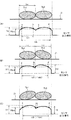
重なり判定部94による重なりの判定を、図12及び図13を参照して説明する。なお、図12(A)は、上記の実施形態で示したように、錠剤Tb1と錠剤Tb2が重なりなく単純に接している場合である。図12(B)は、先行する錠剤Tb1に後続の錠剤Tb2の一部が乗り上げるように重なり合っている場合、図12(C)は、先行する錠剤Tb1の一部が後続の錠剤Tb2に乗り上げるように重なり合っている場合である。 The overlap determination by the overlap determination unit 94 will be described with reference to FIGS. 12 and 13. Note that FIG. 12A shows a case where the tablet Tb1 and the tablet Tb2 are simply in contact with each other without overlapping, as shown in the above embodiment. In FIG. 12B, when a part of the subsequent tablet Tb2 overlaps the preceding tablet Tb1 so as to ride on the subsequent tablet Tb2, FIG. 12C shows that a part of the preceding tablet Tb1 rides on the succeeding tablet Tb2. This is the case when they overlap.

すなわち、上記の第1の実施形態で説明した通り、図12(A)に示すように、2つの錠剤Tb1、Tb2が互いに接して搬送されている場合、センサ30の出力値としきい値Hbrdとの交点として、各錠剤Tb1、Tb2毎に、点aと点b、点cと点dというペアの点が順次検出できる。 That is, as described in the first embodiment described above, when the two tablets Tb1 and Tb2 are transported in contact with each other as shown in FIG. 12A, the output value of the sensor 30 and the threshold value Hbrd As the intersection of the tablets, the points of the pair of points a and b and points c and d can be sequentially detected for each of the tablets Tb1 and Tb2.

また、図12(B)に示すように、錠剤Tb1上に錠剤Tb2が乗ることによる重なりが生じている場合にも、しきい値Hbrdとの交点として、各錠剤Tb毎に点aと点b、点cと点dといったペアの点が検出できる。但し、錠剤Tb1、Tb2同士が、重なりなく接している場合のa‐d間の時間tdxと比べて、重なりが生じている場合のa‐d間の時間td1は短くなる。つまり、td1<tdxとなる。これは、錠剤Tb1の上に錠剤Tb2が重なっていると、平面方向から見て、錠剤Tb2の端部が、錠剤Tb1の端部よりも内側に来るためである。重なり判定部94は、あらかじめしきい値としてtdxを設定しておき、td1<tdxの場合に、重なりが生じていると判定する。 Further, as shown in FIG. 12B, even when the tablet Tb2 is placed on the tablet Tb1 and the tablet Tb2 is overlapped, the points a and b are set as the intersections with the threshold value Hbrd for each tablet Tb. , A pair of points such as point c and point d can be detected. However, the time td1 between a and d when the tablets Tb1 and Tb2 are in contact with each other without overlapping is shorter than the time tdx between a and d when the tablets Tb1 and Tb2 are in contact with each other without overlapping. That is, td1 <tdx. This is because when the tablet Tb2 is overlapped on the tablet Tb1, the end portion of the tablet Tb2 is inside the end portion of the tablet Tb1 when viewed from the plane direction. The overlap determination unit 94 sets tdx as a threshold value in advance, and determines that overlap has occurred when td1 <tdx.

このように、重なり判定部94は、錠剤判定部92が錠剤Tbを識別するために用いるしきい値Hbrdと、センサ30の出力値とに基づいて得られる4点のうち、両端の2点間の時間がしきい値tdxより小さい場合に、重なりが生じていると判定する。 As described above, the overlap determination unit 94 is located between the two points at both ends of the four points obtained based on the threshold value Hbrd used by the tablet determination unit 92 for identifying the tablet Tb and the output value of the sensor 30. When the time of is smaller than the threshold value tdx, it is determined that the overlap has occurred.

これは、図12(C)に示すように、錠剤Tb1が錠剤Tb2に乗ることによる重なりが生じている場合にも同様である。つまり、このような重なりの場合にも、錠剤Tb1、Tb2同士が、重なりなく接している場合のa‐d間の時間tdxと比べて、重なりが生じている場合のa‐d間の時間td2は短くなる。つまり、td2<tdxとなる。このため、重なり判定部94は、td2<tdxの場合、2つの錠剤Tb1、Tb2に重なりが生じていると判定する。 This also applies when the tablet Tb1 overlaps with the tablet Tb2 as shown in FIG. 12 (C). That is, even in the case of such an overlap, the time td2 between a and d when the tablets Tb1 and Tb2 are in contact with each other without overlapping is compared with the time tdx between a and d when they are in contact with each other. Becomes shorter. That is, td2 <tdx. Therefore, when td2 <tdx, the overlap determination unit 94 determines that the two tablets Tb1 and Tb2 are overlapped.

また、錠剤Tbが三つ以上連なる場合においても同様に判定する。この場合は、しきい値Hbrdとの交点として、各錠剤Tb毎に点aと点b、点cと点dといったペアの点が更に連続して検出できる。そして、しきい値tdxとしては、ペアの点の数に応じた倍数とし、両端の2点間の時間がそのしきい値tdxより小さい場合に、重なりが生じていると判定する。 Further, the same determination is made when three or more tablets Tb are connected in a row. In this case, as the intersection with the threshold value Hbrd, a pair of points such as points a and b and points c and d can be detected continuously for each tablet Tb. Then, the threshold value tdx is a multiple corresponding to the number of points in the pair, and when the time between the two points at both ends is smaller than the threshold value tdx, it is determined that the overlap occurs.

さらに、第1の実施形態同様に錠剤Tbのように、センサ30の出力信号が境界を示す波形に基づいて、連なる錠剤の数を算出し、この算出した数で倍数とした実際の錠剤Tbの直径Laの長さと、連なっている各錠剤Tbの長さの両端の錠剤Tbまでの合計長さとを比較し、錠剤Tbの長さLaの倍数より両端の錠剤Tbまでの長さが短い場合に、重なりが生じていると判定しても良い。この場合、図12に示す様な重なりと、図13に示すような重なりが混在し、しきい値Hbrdとの交点として、各錠剤Tb毎に点aと点b、点cと点dといったペアの点が検出できなくても、錠剤Tbの重なりの判定ができる。 Further, like the tablet Tb as in the first embodiment, the number of consecutive tablets is calculated based on the waveform in which the output signal of the sensor 30 indicates the boundary, and the calculated number is a multiple of the actual tablet Tb. Comparing the length of the diameter La with the total length of each tablet Tb in a row up to the tablet Tb at both ends, when the length to the tablet Tb at both ends is shorter than a multiple of the length La of the tablet Tb. , It may be determined that the overlap has occurred. In this case, the overlap as shown in FIG. 12 and the overlap as shown in FIG. 13 are mixed, and as the intersection with the threshold value Hbrd, a pair such as a point a and a point b and a point c and a point d for each tablet Tb. Even if the point is not detected, the overlap of the tablets Tb can be determined.

なお、図13に示すように、錠剤Tb2が錠剤Tb1に対して大きく重なっていることにより、錠剤Tb1と錠剤Tb2間の境界が、しきい値Hbrdを超えてしまう場合、錠剤Tbが2錠存在しているにも拘わらず、しきい値Hbrdとの交点がa−bの2点になってしまう。しかしながら、重なりがない場合の錠剤Tb1(あるいは錠剤Tb2)の1錠分のa−b間の時間tbxと比べて、錠剤Tb1と錠剤Tb2とが大きく重なっている場合のa−b間の時間tbが長くなる。つまり、tb>tbxとなる。このため、重なり判定部94は、あらかじめしきい値としてtbxを設定しておき、tb>tbxの場合に、重なりが生じていると判定する。 As shown in FIG. 13, when the boundary between the tablet Tb1 and the tablet Tb2 exceeds the threshold value Hbrd due to the large overlap of the tablet Tb2 with respect to the tablet Tb1, two tablets Tb are present. Despite this, the intersection with the threshold value Hbrd becomes two points ab. However, compared to the time tbx between a and b of one tablet Tb1 (or tablet Tb2) when there is no overlap, the time tb between a and b when the tablet Tb1 and the tablet Tb2 overlap significantly. Becomes longer. That is, tb> tbx. Therefore, the overlap determination unit 94 sets tbx as a threshold value in advance, and determines that overlap has occurred when tb> tbx.

不良判定部95は、重なり判定部94により重なっていると判定された錠剤Tb1、Tb2については、不良と判定する。これは、錠剤Tbが重なっている場合、錠剤Tbの印刷する部分が覆い隠されたり、錠剤Tbの姿勢が斜めとなって印刷が正常にできなくなる可能性があるためである。第1の実施形態と同様、不良と判定されなかった錠剤Tbに印刷が行われ、不良と判定された錠剤Tbは、印刷、撮像等が行われず、排出装置60により排出され、回収装置70に回収される。例えば、外観不良ではないが、姿勢等により印刷がなされなかった錠剤Tbと同様に、回収トレイ71に回収される。 The defect determination unit 95 determines that the tablets Tb1 and Tb2 that are determined to overlap by the overlap determination unit 94 are defective. This is because when the tablets Tb overlap, the portion to be printed on the tablets Tb may be obscured, or the posture of the tablets Tb may become slanted and printing may not be performed normally. Similar to the first embodiment, printing is performed on the tablet Tb that is not determined to be defective, and the tablet Tb determined to be defective is not printed, imaged, or the like, and is discharged by the discharge device 60 and sent to the recovery device 70. Will be recovered. For example, it is collected in the collection tray 71 in the same manner as the tablet Tb which is not bad in appearance but is not printed due to the posture or the like.

以上のように、本実施形態は、高さ位置の変動情報に基づいて、錠剤Tbの重なり合いを判定する重なり判定部94を有し、不良判定部95は、重なり判定部94による判定結果に応じて、錠剤Tbが不良か否かを判定する。このため、互いに接して搬送されている錠剤Tbであっても、重なりのある錠剤Tbについては、表面の隠れ、傾斜等により印刷に適さない錠剤Tbとして、あらかじめ印刷の対象から除外することができる。これにより、後続の撮像、不良判定、印刷等の処理負担を軽減できる。特に、不良判定を行うための撮像部の撮像回数を節約して、データ容量を軽減できる。
[第3の実施形態]
本実施形態は、基本的には上記の第2の実施形態と同様の構成である。但し、本実施形態は、重なり判定部94が、錠剤Tb同士の重なり合いを判定するのみならず、重なり合った錠剤Tbの上下関係も判定し、この結果に基づいて不良判定部95によって不良の判定をする。
As described above, the present embodiment has an overlap determination unit 94 that determines the overlap of the tablets Tb based on the height position fluctuation information, and the defect determination unit 95 responds to the determination result by the overlap determination unit 94. It is determined whether or not the tablet Tb is defective. Therefore, even if the tablets Tb are transported in contact with each other, the overlapping tablets Tb can be excluded from the printing target in advance as tablets Tb that are not suitable for printing due to surface hiding, inclination, or the like. .. As a result, it is possible to reduce the processing load of subsequent imaging, defect determination, printing, and the like. In particular, the data capacity can be reduced by saving the number of times of imaging of the imaging unit for performing defect determination.
[Third Embodiment]
This embodiment basically has the same configuration as the second embodiment described above. However, in the present embodiment, the overlap determination unit 94 not only determines the overlap between the tablets Tb, but also determines the vertical relationship of the overlapping tablets Tb, and the defect determination unit 95 determines the defect based on this result. To do.

この重なり判定部94による上下関係の判定を、図12、図14を参照して説明する。すなわち、図12(B)に示すように、錠剤Tb1に錠剤Tb2の一部が乗り上げるように重なっている場合、錠剤Tb1のa‐b間のセンサ30の出力値のピーク値H1よりも、錠剤Tb2のc−d間のセンサ30の出力値のピーク値H2の方が大きい。つまり、H1<H2である。このため、ピーク値H2が大きい方の錠剤Tb2が、上にあると判定する。このように、重なり判定部94は、重なっていると判定された錠剤Tb1、Tb2について、センサ30の高さ位置を示す波形のピーク値を比較して、上下関係を判定する。 The determination of the vertical relationship by the overlap determination unit 94 will be described with reference to FIGS. 12 and 14. That is, as shown in FIG. 12 (B), when a part of the tablet Tb2 overlaps the tablet Tb1 so as to ride on the tablet Tb1, the tablet Tb1 is more than the peak value H1 of the output value of the sensor 30 between a and b of the tablet Tb1. The peak value H2 of the output value of the sensor 30 between cd of Tb2 is larger. That is, H1 <H2. Therefore, it is determined that the tablet Tb2 having the larger peak value H2 is on the top. In this way, the overlap determination unit 94 compares the peak values of the waveforms indicating the height positions of the sensors 30 with respect to the tablets Tb1 and Tb2 determined to overlap, and determines the hierarchical relationship.

これは、図12(C)に示すように、錠剤Tb1の一部が錠剤Tb2に乗り上げるように重なっている場合にも同様である。つまり、このような重なりの場合には、錠剤Tb1のa‐b間のセンサ30の出力値のピーク値H1の方が、錠剤Tb2のc−d間のセンサ30の出力値のピーク値H2よりも大きい。つまり、H1>H2である。このため、ピーク値H1が大きい方の錠剤Tb1が、上にあると判定する。 This is also the case when a part of the tablet Tb1 is overlapped so as to ride on the tablet Tb2 as shown in FIG. 12 (C). That is, in the case of such an overlap, the peak value H1 of the output value of the sensor 30 between a and b of the tablet Tb1 is higher than the peak value H2 of the output value of the sensor 30 between cd of the tablet Tb2. Is also big. That is, H1> H2. Therefore, it is determined that the tablet Tb1 having the larger peak value H1 is on the top.

なお、錠剤Tbが三つ以上連なる場合においても同様に判定する。すなわち、隣合う錠剤Tbの、それぞれの錠剤Tbのしきい値Hbrdとの交点間のセンサ30の出力値のピーク値を順次比較することで、それぞれの錠剤Tbの上下関係を判定することができる。 The same determination is made when three or more tablets Tb are connected in a row. That is, the hierarchical relationship of each tablet Tb can be determined by sequentially comparing the peak value of the output value of the sensor 30 between the intersections of the adjacent tablets Tb with the threshold value Hbrd of each tablet Tb. ..

このように、互いに重なっていると判定された錠剤Tbであって、上にあると判定された錠剤Tbは、印刷する部分である上面側が全て露出している。このため、本実施形態では、この段階において、不良判定部95は上にあると判定された錠剤Tbについては不良とは判定しない。但し、不良判定部95は、カメラ40にて撮像された画像に基づいて不良判定を行い、不良であると判定された錠剤Tbは、上述の各実施形態と同様、印刷は行われず、不良として追跡される。不良であると判定されなかった錠剤Tbは、印刷の対象となる。また、不良判定部95は、印刷確認カメラ52にて撮像された画像に基づいて不良判定を行い、不良であると判定された錠剤Tbは、不良として追跡される。その後の処理は、上述の各実施形態と同様である。 As described above, the tablet Tb determined to be overlapped with each other and the tablet Tb determined to be on the upper surface are all exposed on the upper surface side which is the printing portion. Therefore, in the present embodiment, at this stage, the defect determination unit 95 does not determine that the tablet Tb determined to be above is defective. However, the defect determination unit 95 determines the defect based on the image captured by the camera 40, and the tablet Tb determined to be defective is not printed as in each of the above-described embodiments, and is regarded as a defect. Be tracked. Tablets Tb that are not determined to be defective are subject to printing. Further, the defect determination unit 95 makes a defect determination based on the image captured by the print confirmation camera 52, and the tablet Tb determined to be defective is tracked as a defect. Subsequent processing is the same as in each of the above-described embodiments.

下にあると判定された錠剤Tbについては、印刷する部分である上面側の一部が隠れている。このため、不良判定部95により不良と判定され印刷せず、その後、一旦生成したトリガ信号を消去し、回収トレイ71に回収される。 For the tablet Tb determined to be underneath, a part of the upper surface side, which is the part to be printed, is hidden. Therefore, the defect determination unit 95 determines that the defect is defective and does not print, and then the trigger signal once generated is erased and collected in the collection tray 71.

以上のように、本実施形態では、重なり判定部94は、高さ位置の変動情報に基づいて、重なり合った錠剤Tbの上下関係を判定する。このため、重なり合った錠剤Tbを一律に撮像、印刷等の対象から排除するのではなく、印刷する部分である上面側が全て露出している上側の錠剤Tbについては、不良でなければ印刷等の対象となるので、印刷されない錠剤Tbの増加を抑えることができる。
[第4の実施形態]
本実施形態は、基本的には上記の第3の実施形態と同様の構成である。但し、本実施形態は、図14に示すように、傾き判定部94a、長さ判定部94bを有する。傾き判定部94aは、重なり判定部94により互いに重なっていると判定された錠剤Tbについて、センサ30からの錠剤Tbの高さ位置の変化情報に基づいて、錠剤Tbの傾きを判定する。傾きの判定は、センサ30が、搬送方向Dに時系列で検出した1つの錠剤Tbの2箇所の高さにより求めることができる。
As described above, in the present embodiment, the overlap determination unit 94 determines the vertical relationship of the overlapping tablets Tb based on the height position variation information. For this reason, the overlapping tablet Tb is not uniformly excluded from the objects to be imaged, printed, etc., but the upper tablet Tb, which is the part to be printed and the upper surface side is entirely exposed, is subject to printing, etc. if it is not defective. Therefore, it is possible to suppress an increase in unprinted tablets Tb.
[Fourth Embodiment]
This embodiment basically has the same configuration as the third embodiment described above. However, as shown in FIG. 14, the present embodiment has an inclination determination unit 94a and a length determination unit 94b. The tilt determination unit 94a determines the inclination of the tablet Tb based on the change information of the height position of the tablet Tb from the sensor 30 for the tablet Tb determined to overlap each other by the overlap determination unit 94. The inclination can be determined by the heights of two points of one tablet Tb detected by the sensor 30 in the transport direction D in time series.

長さ判定部94bは、重なり判定部94により重なりが生じていると判定された錠剤Tbについて、センサ30からの錠剤Tbの高さ位置の変化情報に基づいて、錠剤Tbの搬送方向Dの長さを判定する。長さの判定は、第1の実施形態において前述した通り錠剤判定部92により識別される錠剤Tbの境界から境界までの搬送時間と、搬送速度により求めることができる。 The length determination unit 94b determines the length of the tablet Tb in the transport direction D based on the change information of the height position of the tablet Tb from the sensor 30 for the tablet Tb determined to be overlapped by the overlap determination unit 94. Judge. The length can be determined by the transfer time from the boundary to the boundary of the tablet Tb identified by the tablet determination unit 92 and the transfer speed as described above in the first embodiment.

ここでいう錠剤Tbの長さは、センサ30により検出される錠剤Tbの搬送方向Dの長さであり、錠剤Tbが通過する位置、錠剤Tbが搬送される態様によって異なる。例えば、図3に示すように、錠剤Tbが間隔を空けて搬送されてきた場合、錠剤Tbの中心を通過する位置を検出したとすると、錠剤Tbの長さは、ほぼ実際の錠剤Tbの直径Laとなる。図12(A)に示すように、2つの錠剤Tb同士が接しているが、上下に重ならずに搬送されてきた場合には、間隔を空けて搬送されてきた場合と同様である。 The length of the tablet Tb referred to here is the length in the transport direction D of the tablet Tb detected by the sensor 30, and differs depending on the position through which the tablet Tb passes and the mode in which the tablet Tb is transported. For example, as shown in FIG. 3, when the tablet Tb is transported at intervals, if the position passing through the center of the tablet Tb is detected, the length of the tablet Tb is almost the actual diameter of the tablet Tb. It becomes La. As shown in FIG. 12 (A), the two tablets Tb are in contact with each other, but when they are transported without overlapping on the top and bottom, it is the same as when they are transported at intervals.

しかし、2つ以上の錠剤Tbが重なって搬送されてきた場合等においては、実際の錠剤Tbの直径Laとは異なる。例えば、錠剤Tbが重なっていることにより、傾斜していたり、一部分が隠れていたりすると、センサ30により検出される錠剤Tbの長さは、錠剤Tbの直径よりも短くなる。図12(B)では、重なり合っている場合の下側の錠剤Tb1の長さをLu、上側の錠剤Tb2の長さをLoで示している。この図の例では、LuもLoも、錠剤Tbの本来の直径Laよりも短くなっている。 However, when two or more tablets Tb are transported in an overlapping manner, the diameter La of the actual tablet Tb is different from that of the actual tablet Tb. For example, if the tablets Tb are overlapped and tilted or partly hidden, the length of the tablet Tb detected by the sensor 30 becomes shorter than the diameter of the tablet Tb. In FIG. 12B, the length of the lower tablet Tb1 in the case of overlapping is shown by Lu, and the length of the upper tablet Tb2 is shown by Lo. In the example of this figure, both Lu and Lo are shorter than the original diameter La of the tablet Tb.

不良判定部95は、傾き判定部94aが判定した錠剤Tbの傾き及び長さ判定部94bが判定した錠剤Tbの搬送方向長さに基づいて、互いに重なり合っている錠剤Tbそれぞれが、不良であるか否かについてを判定する。 The defect determination unit 95 determines whether the tablets Tb overlapping each other are defective based on the inclination of the tablet Tb determined by the inclination determination unit 94a and the transport direction length of the tablet Tb determined by the length determination unit 94b. Judge whether or not.

より具体的な不良判定の例を、図15を参照して説明する。図15では、上下に重なり合っている錠剤Tbのうち、下側の錠剤Tbを錠剤Tb1、上側の錠剤Tbを錠剤Tb2とする。また、不良判定するしきい値として、印刷できる錠剤Tbの傾きの最大値を示すしきい値θx、印刷できる錠剤Tbの長さの最小値を示すしきい値Lxが設定されているものとする。印刷ヘッド51は、錠剤Tbの傾きに応じた印刷パターンで正しく印刷できるように調整するが、この調整可能な限界を超える傾きがある場合、印刷した文字やマーク等がずれてしまう。このため、調整可能な限界として、しきい値θxを設定し、このしきい値θx以下の傾きであれば、不良でないと判定できる。なお、錠剤Tbの傾きに応じた印刷パターンの調整は、同一の錠剤Tbの傾斜した印刷面に対して、例えば、インクの吐出範囲、吐出量、インク滴のピッチ等を変化させることにより行う。また、錠剤Tbが重なりにより一部が隠れている場合、上記の実施形態では、印刷の対象から排除していたが、隠れている部分がごく僅かで、露出部分が大きい場合には、印刷ができる場合がある。このため、印刷可能な限界として、しきい値Lxを設定し、このしきい値Lx以上の長さであれば、不良でないと判定できる。 A more specific example of defect determination will be described with reference to FIG. In FIG. 15, among the tablet Tb that overlaps vertically, the lower tablet Tb is referred to as tablet Tb1 and the upper tablet Tb is referred to as tablet Tb2. Further, it is assumed that a threshold value θx indicating the maximum value of the inclination of the tablet Tb that can be printed and a threshold value Lx indicating the minimum value of the length of the tablet Tb that can be printed are set as the threshold value for determining the defect. .. The print head 51 is adjusted so that it can print correctly with a print pattern corresponding to the inclination of the tablet Tb, but if there is an inclination exceeding this adjustable limit, the printed characters, marks, and the like will be displaced. Therefore, a threshold value θx is set as an adjustable limit, and if the slope is equal to or less than this threshold value θx, it can be determined that the product is not defective. The printing pattern is adjusted according to the inclination of the tablet Tb by changing, for example, the ink ejection range, the ejection amount, the ink droplet pitch, and the like on the inclined printing surface of the same tablet Tb. Further, when the tablets Tb are partially hidden due to overlapping, they are excluded from the printing target in the above embodiment, but when the hidden part is very small and the exposed part is large, printing is performed. You may be able to do it. Therefore, a threshold value Lx is set as the printable limit, and if the length is equal to or longer than the threshold value Lx, it can be determined that the product is not defective.

さらに、図15において、図12で示したと同様に、Luは、長さ判定部94bが判定した下側の錠剤Tb1の搬送方向Dの長さ、Loは、長さ判定部94bが判定した上側の錠剤Tb2の搬送方向Dの長さである。dは、重なり合っている部分の搬送方向Dの長さである。θは、傾き判定部94aが判定した上側の錠剤Tb2の傾きである。 Further, in FIG. 15, as shown in FIG. 12, Lu is the length of the lower tablet Tb1 determined by the length determination unit 94b in the transport direction D, and Lo is the upper side determined by the length determination unit 94b. It is the length of the tablet Tb2 in the transport direction D. d is the length of the overlapping portion in the transport direction D. θ is the inclination of the upper tablet Tb2 determined by the inclination determination unit 94a.

まず、上記の実施形態で説明したように、重なり判定部94が、互いに重なっている錠剤Tb1、Tb2について、錠剤Tb1が下側、錠剤Tb2が上側と判定する。そして、不良判定部95は、下側の錠剤Tb1については、長さLuとしきい値Lxとの比較により、上側の錠剤Tb2については、傾きθとしきい値θxとの比較により、不良か否かを判定する。 First, as described in the above embodiment, the overlap determination unit 94 determines that the tablets Tb1 and Tb2 that overlap each other have the tablet Tb1 on the lower side and the tablet Tb2 on the upper side. Then, the defect determination unit 95 determines whether or not the lower tablet Tb1 is defective by comparing the length Lu and the threshold value Lx, and the upper tablet Tb2 by comparing the inclination θ and the threshold value θx. To judge.

すなわち、図15(A)は、下側の錠剤Tb1の搬送方向Dの長さLuがしきい値Lxと同じで、上側の錠剤Tb2の傾きθがしきい値θxよりも小さい場合である。この場合、錠剤Tb1については、重なり部分dが短く、印刷すべき表面の露出部分が大きいため、不良判定部95は不良と判定しない。また、錠剤Tb2についても、傾きが許容範囲内であるため、不良判定部95は不良と判定しない。 That is, FIG. 15A shows a case where the length Lu of the lower tablet Tb1 in the transport direction D is the same as the threshold value Lx, and the inclination θ of the upper tablet Tb2 is smaller than the threshold value θx. In this case, since the overlapping portion d of the tablet Tb1 is short and the exposed portion of the surface to be printed is large, the defect determination unit 95 does not determine that the tablet Tb1 is defective. Further, since the inclination of the tablet Tb2 is within the allowable range, the defect determination unit 95 does not determine that the tablet Tb2 is defective.

次に、図15(B)は、下側の錠剤Tb1の搬送方向Dの長さLuがしきい値Lxよりも短く、上側の錠剤Tb2の傾きθがしきい値θxと等しい場合である。この場合、錠剤Tb1は、重なり部分dが長く、印刷すべき表面が隠れてしまっている部分が大きいため、不良判定部95は不良と判定する。一方、錠剤Tb2は、傾きが許容範囲内であるため、不良判定部95は不良と判定しない。 Next, FIG. 15B shows a case where the length Lu of the lower tablet Tb1 in the transport direction D is shorter than the threshold value Lx and the inclination θ of the upper tablet Tb2 is equal to the threshold value θx. In this case, since the overlapping portion d of the tablet Tb1 is long and the surface to be printed is hidden in a large portion, the defect determination unit 95 determines that the tablet Tb1 is defective. On the other hand, since the inclination of the tablet Tb2 is within the permissible range, the defect determination unit 95 does not determine that it is defective.

さらに、図15(C)は、下側の錠剤Tb1の搬送方向Dの長さLuがしきい値Lxよりも短く、上側の錠剤Tb2の傾きθがしきい値θxよりも大きい場合である。この場合、錠剤Tb1は、重なり部分dが長く、印刷すべき表面が隠れてしまっている部分が大きいため、不良判定部95は不良と判定する。また、錠剤Tb2は、印刷すべき表面は隠されていないが、傾きが許容範囲外であるため、不良判定部95は不良と判定する。 Further, FIG. 15C shows a case where the length Lu of the lower tablet Tb1 in the transport direction D is shorter than the threshold value Lx and the inclination θ of the upper tablet Tb2 is larger than the threshold value θx. In this case, since the overlapping portion d of the tablet Tb1 is long and the surface to be printed is hidden in a large portion, the defect determination unit 95 determines that the tablet Tb1 is defective. Further, although the surface of the tablet Tb2 to be printed is not hidden, the inclination is out of the permissible range, so the defect determination unit 95 determines that the tablet Tb2 is defective.

傾き判定部94aおよび長さ判定部94bの判定結果に基づき、不良判定部95により不良と判定された錠剤Tbであっても、さらに、カメラ40による撮像で得られた画像に基づく不良判定部94による不良判定の結果、不良でないと判定されれば、良品として印刷がなされる。不良判定部95により不良と判定された錠剤Tbについては、一旦生成したトリガ信号を消去し、印刷がなされなかった錠剤Tbとして、回収トレイ71に回収される。 Even if the tablet Tb is determined to be defective by the defect determination unit 95 based on the determination results of the tilt determination unit 94a and the length determination unit 94b, the defect determination unit 94 based on the image obtained by the image taken by the camera 40 is further obtained. If it is determined that the product is not defective as a result of the defect determination by, the product is printed as a non-defective product. The tablet Tb determined to be defective by the defect determination unit 95 is erased from the trigger signal once generated, and is collected in the collection tray 71 as the unprinted tablet Tb.

本実施形態は、センサ30により検出される錠剤Tbの高さ位置の変動情報に基づいて、錠剤Tbの傾きを判定する傾き判定部94aと、センサ30により検出される錠剤Tbの高さ位置の変動情報に基づいて、錠剤Tbの搬送方向Dの長さを判定する長さ判定部94bとを有し、不良判定部95は、錠剤Tbの傾き及び錠剤Tbの搬送方向Dの長さに基づいて、互いに重なり合っている錠剤Tbが不良か否かを判定する。 In this embodiment, the tilt determination unit 94a for determining the inclination of the tablet Tb based on the fluctuation information of the height position of the tablet Tb detected by the sensor 30, and the height position of the tablet Tb detected by the sensor 30. It has a length determination unit 94b for determining the length of the tablet Tb in the transport direction D based on the fluctuation information, and the defect determination unit 95 is based on the inclination of the tablet Tb and the length of the tablet Tb in the transport direction D. Then, it is determined whether or not the tablets Tb overlapping each other are defective.

このため、重なり合っている錠剤Tbのうち、印刷できる錠剤Tb、印刷できない錠剤Tbを正確に判断して、印刷されない錠剤Tbを減らすことができる。
[他の実施形態]
本発明は、上記の実施形態には限定されない。
(1)錠剤判定部92のトリガ信号の生成のタイミングは、上記には限定されない。例えば、センサ30の出力信号の立ち上がり、錠剤Tbの境界又はピーク等を検知したら、すぐにトリガ信号を生成してもよい。一旦生成したトリガ信号を、印刷不可、不良判定等の結果に基づいて、消去することにより、該当する錠剤Tbのその後の処理を省略してもよい。
Therefore, among the overlapping tablets Tb, the tablets Tb that can be printed and the tablets Tb that cannot be printed can be accurately determined, and the tablets Tb that are not printed can be reduced.
[Other Embodiments]
The present invention is not limited to the above embodiments.
(1) The timing of generating the trigger signal of the tablet determination unit 92 is not limited to the above. For example, a trigger signal may be generated immediately after detecting the rise of the output signal of the sensor 30, the boundary or peak of the tablet Tb, and the like. The subsequent processing of the corresponding tablet Tb may be omitted by erasing the once generated trigger signal based on the results of non-printability, defect determination, and the like.

上記の実施形態では、トリガ信号は、各錠剤Tbを識別した場合、錠剤判定部92によって生成し、そのトリガ信号は、錠剤Tbを識別した後のカメラ40、印刷確認カメラ52による撮像、印刷ヘッド51を用いた印刷等の処理のタイミングを適切なものとするタイミングで生成されるとしたが、これに限られず、錠剤判定部92が生成するトリガ信号に基づいて、その他の制御装置90の部分が後の処理のトリガ信号を生成しても良い。すなわちトリガ信号は必ずしも同じ手段で生成されなくても良い。また、錠剤判定部92が、錠剤Tbを識別した場合に生成したトリガ信号を基準にして、その後の処理を行っても良い。すなわち、各処理を行うためのそれぞれトリガ信号を生成せず、基準とするトリガ信号からの各処理までの時間や搬送距離、搬送位置に達するタイミングで各処理を行うことでも良い。
(2)不良判定部95による不良か否かの判定は、不良であると判定してそれ以外を良品とする場合であっても、良品であると判定してそれ以外を不良と判定する場合であってもよい。また、不良判定部95による不良か否かの判定は、上記のように、センサ30による検出時、カメラ40による撮像時、印刷確認カメラ52による撮像時に行われるが、検出部であるセンサ30による高さ位置の変動情報検出時に不良と判定した場合であっても、撮像部であるカメラ40による画像データに基づいて不良でないと判定できる場合には、不良として扱わない設定も可能である。このように2段階で判定することにより、より正確に印刷の可否を決定できる。また、センサ30による高さ位置の変動情報に基づく不良判定を省略して、処理を簡素化することもできる。
(3)重なり判定部94による重なり判定を、錠剤Tbの高さの比較のみによって行ってもよい。つまり、図12(B)、(C)に示したように、2つの錠剤Tb1、Tb2に重なりがある場合、H1<H2又はH1>H2となる。このため、錠剤Tb1、Tb2のピーク値H1、H2を比較して両者が相違する場合に、重なりが生じていると判定できる。これにより、重なり判定の処理を簡素化できる。また、この比較により、錠剤Tb1と錠剤Tb2の上下関係も判定できることは、上記の通りである。なお、上記の第3の実施形態も同様であるが、重なりが生じていなくても、錠剤Tbの高さには僅かな相違が生じることも考慮して、錠剤Tbの高さの比較判定については、同一の高さと判定できる値に幅を設けてもよい。つまり、H1とH2の差分の絶対値が、しきい値を超える場合に、高さに相違があると判定してもよい。
(4)カメラ40を設置しない態様も構成可能である。つまり、上記の実施形態では、トリガ信号が生成された錠剤Tbに対し、カメラ40が撮像し、その撮像画像に基づいて、印刷等を処理している。しかし、カメラ40を省略して、不良判定部95により不良と判定された錠剤Tbに対しては印刷部50による印刷をせず、不良でないと判定された錠剤Tbに対して印刷部50による印刷をしてもよい。この場合であっても、2以上の錠剤Tbが接して搬送されている場合の処理は同様にできる。
(5)排出装置60による排出、回収装置70による回収は、外観不良の錠剤Tb、印刷不良の錠剤Tb、姿勢不良で印刷されなかった錠剤Tbを、不良判定部95により印刷不可と判定されて印刷されなかった錠剤Tbを、区別して排出し、回収してもよい。つまり、回収トレイをそれぞれの錠剤Tbに対応して用意しておき、各回収トレイに対応する位置に来た時に、排出装置60が排出すればよい。また、これらの錠剤Tbを全て同じ回収トレイに回収してもよい。
(6)上記の実施形態は、錠剤Tbの一方の面に印刷する錠剤印刷装置Sとして説明した。但し、本発明は、上記と同様の構成の搬送装置、センサ、カメラ、印刷機構、排出装置、回収装置、収納装置を追加して、錠剤Tbの両面に印刷を可能とする錠剤印刷装置Sとして構成することもできる。この場合、搬送装置20の良品が離脱する位置において、収納装置80ではなく、追加された搬送装置が良品を、他方の面が印刷される面となるように受け取る。そして、追加されたセンサ、カメラ、印刷機構、排出装置、回収装置、収納装置によって、上記と同様に、他方の面への印刷、不良品の回収、良品の収納が行われる。
In the above embodiment, when each tablet Tb is identified, the trigger signal is generated by the tablet determination unit 92, and the trigger signal is captured by the camera 40 and the print confirmation camera 52 after the tablet Tb is identified, and the print head. It is said that it is generated at a timing that makes the timing of processing such as printing using 51 appropriate, but it is not limited to this, and the other part of the control device 90 is based on the trigger signal generated by the tablet determination unit 92. May generate a trigger signal for later processing. That is, the trigger signal does not necessarily have to be generated by the same means. Further, the subsequent processing may be performed based on the trigger signal generated when the tablet determination unit 92 identifies the tablet Tb. That is, it is also possible to perform each process at the time from the reference trigger signal to each process, the transfer distance, and the timing of reaching the transfer position, without generating the trigger signal for each process.
(2) The defect determination unit 95 determines whether or not the product is defective, even if it is determined to be defective and the other products are considered to be non-defective products, but the products are determined to be non-defective products and the other products are determined to be defective. It may be. Further, as described above, the defect determination unit 95 determines whether or not the defect is defective when the sensor 30 detects, the camera 40 captures the image, and the print confirmation camera 52 captures the image, but the sensor 30 which is the detection unit determines. Even if it is determined to be defective when the height position fluctuation information is detected, it can be set not to be treated as defective if it can be determined that it is not defective based on the image data by the camera 40 which is the imaging unit. By making a determination in two steps in this way, it is possible to determine whether or not printing is possible more accurately. It is also possible to simplify the process by omitting the defect determination based on the height position fluctuation information by the sensor 30.
(3) The overlap determination by the overlap determination unit 94 may be performed only by comparing the heights of the tablets Tb. That is, as shown in FIGS. 12B and 12C, when the two tablets Tb1 and Tb2 overlap, H1 <H2 or H1> H2. Therefore, when the peak values H1 and H2 of the tablets Tb1 and Tb2 are compared and the two are different, it can be determined that the overlap occurs. As a result, the overlap determination process can be simplified. Further, as described above, the hierarchical relationship between the tablet Tb1 and the tablet Tb2 can be determined by this comparison. The same applies to the third embodiment described above, but in consideration of the fact that the heights of the tablets Tb may differ slightly even if they do not overlap, the comparative determination of the heights of the tablets Tb May provide a width at a value that can be determined to be the same height. That is, when the absolute value of the difference between H1 and H2 exceeds the threshold value, it may be determined that there is a difference in height.
(4) A mode in which the camera 40 is not installed can also be configured. That is, in the above embodiment, the camera 40 takes an image of the tablet Tb for which the trigger signal is generated, and printing or the like is processed based on the captured image. However, the camera 40 is omitted, and the tablet Tb determined to be defective by the defect determination unit 95 is not printed by the printing unit 50, and the tablet Tb determined to be non-defective is printed by the printing unit 50. You may do. Even in this case, the process when two or more tablets Tb are in contact with each other and transported can be performed in the same manner.
(5) In the discharge by the discharge device 60 and the recovery by the recovery device 70, the tablet Tb having a poor appearance, the tablet Tb having a poor print, and the tablet Tb not printed due to a poor posture are determined by the defect determination unit 95 to be unprintable. The unprinted tablets Tb may be discharged separately and collected. That is, a collection tray may be prepared corresponding to each tablet Tb, and the discharge device 60 may discharge when the position corresponding to each collection tray is reached. Moreover, you may collect all these tablets Tb in the same collection tray.
(6) The above embodiment has been described as a tablet printing device S that prints on one side of the tablet Tb. However, the present invention is a tablet printing device S capable of printing on both sides of the tablet Tb by adding a transport device, a sensor, a camera, a printing mechanism, a discharging device, a collecting device, and a storage device having the same configuration as described above. It can also be configured. In this case, at the position where the non-defective product of the transport device 20 is separated, the added transport device, not the storage device 80, receives the non-defective product so that the other side is the printed side. Then, the added sensor, camera, printing mechanism, ejection device, collection device, and storage device perform printing on the other surface, collection of defective products, and storage of non-defective products in the same manner as described above.

また、排出装置、回収装置、収納装置は、追加された搬送装置にのみ配置し、追加された搬送装置にて不良品の回収、印刷されなかった錠剤Tbの回収、良品の収納としても良い。この場合は、搬送装置20に供給された錠剤Tbは排出されることなくそのまま追加された搬送装置に受け渡される。搬送装置20で判定された結果は追加された搬送装置での錠剤Tbの印刷処理等にも適用される。
(7)実施形態において、設定した各種の値に対する大小判断、一致不一致の判断等において、以上、以下として値を含めるように判断するか、より大きい、上回る、超える、より小さい、下回る、未満として値を含めないように判断するかの設定は自由である。
(8)錠剤Tbは、搬送ベルト21の通孔26の配列ライン上に供給される。したがって、センサ30もこの通孔26の配列ライン上に配置される。錠剤Tbが接して搬送されてくる場合、その接点は概ねこの通孔26の配列ライン上となる。つまり、錠剤Tbの境目が接した状態となってセンサ30を通過することになり、錠剤Tbの形状によっては、その境目がセンサ30の出力信号では見分けられない場合も考えられる。そこで、センサ30を通孔26の配列ライン上から、搬送方向Dの直交方向にずらして配置しても良い。こうするとセンサ30が検出する位置が錠剤Tb同士の接点を避けることになり、錠剤Tbの境目を検出しやすくなる。
(9)センサ30は、1つには限定されず、複数配置してもよい。例えば、図16に示すように、2つのセンサ31、32を、搬送方向Dとは直交する方向に2個配置するとよい。図16に示すように、隆起等の少ない平板状の錠剤Tbが接して搬送されて来るような場合、境目での信号出力値の低下があまり望めない。ところが、1つのセンサ31を通孔26の配列ライン上に、もう1つのセンサ32は、通孔26の配列ライン上から、例えば錠剤Tbの直径の1/4程度離れた位置に配置することで、少なくとも一方のセンサ32からの出力値においては、境目の信号が鮮明となる可能性が高い。この場合、しきい値Hbrdとの交点が、1つの錠剤Tbに対してセンサ31からの信号a−b、センサ32からのa’−b’の信号が2つのペアで得られる。これについては、2つのペアのそれぞれの中間点を求め、その平均値をとることが考えられる。
Further, the discharging device, the collecting device, and the storing device may be arranged only in the added transport device, and the added transport device may be used to collect defective products, collect unprinted tablet Tb, and store non-defective products. In this case, the tablet Tb supplied to the transfer device 20 is delivered to the added transfer device as it is without being discharged. The result determined by the transfer device 20 is also applied to the printing process of the tablet Tb by the added transfer device.
(7) In the embodiment, in the judgment of the magnitude of the set various values, the judgment of the match / mismatch, etc., it is determined to include the values as above or below, or as greater than, greater than, greater than, less than, less than, less than You are free to set whether to decide not to include the value.
(8) The tablet Tb is supplied on the arrangement line of the through hole 26 of the transport belt 21. Therefore, the sensor 30 is also arranged on the arrangement line of the through holes 26. When the tablets Tb are brought into contact with each other, the contact points are generally on the arrangement line of the through holes 26. That is, the boundary of the tablet Tb is in contact with the sensor 30 and passes through the sensor 30, and depending on the shape of the tablet Tb, the boundary may not be distinguished by the output signal of the sensor 30. Therefore, the sensor 30 may be arranged so as to be offset in the direction orthogonal to the transport direction D from the arrangement line of the through holes 26. In this way, the position detected by the sensor 30 avoids the contact points between the tablets Tb, and it becomes easier to detect the boundary between the tablets Tb.
(9) The number of sensors 30 is not limited to one, and a plurality of sensors 30 may be arranged. For example, as shown in FIG. 16, two sensors 31 and 32 may be arranged in a direction orthogonal to the transport direction D. As shown in FIG. 16, when the flat tablet Tb having few ridges or the like is brought into contact with the tablet Tb, a decrease in the signal output value at the boundary cannot be expected so much. However, by arranging one sensor 31 on the arrangement line of the through hole 26 and the other sensor 32 at a position separated from the arrangement line of the through hole 26, for example, about 1/4 of the diameter of the tablet Tb. At least at the output value from one of the sensors 32, there is a high possibility that the boundary signal will be clear. In this case, two pairs of signals ab from the sensor 31 and a'-b'signals from the sensor 32 are obtained for one tablet Tb at the intersection with the threshold value Hbrd. For this, it is conceivable to find the midpoint of each of the two pairs and take the average value.

また、図17に示すように、錠剤Tb1が錠剤Tbと、上下方向ではなく、水平方向にずれて重なっている場合にも、複数のセンサ30の配置が有効である。図17において、a−d間の時間td3は、tdxよりも短くなる。但し、この場合、H1=H2となるため、重なり判定部94は、上下の重なりではないと判定することができる。さらに、このような錠剤Tb1と錠剤Tb2とが水平方向にずれて重なっている場合には、搬送方向Dと直交する方向に、センサ30を追加してさらに設けることによってより正確に錠剤Tbそれぞれの状態を把握することができ、その後の不良判定および印刷パターンの調整が容易になる。 Further, as shown in FIG. 17, the arrangement of the plurality of sensors 30 is effective even when the tablet Tb1 overlaps the tablet Tb with a deviation in the horizontal direction instead of the vertical direction. In FIG. 17, the time td3 between a and d is shorter than tdx. However, in this case, since H1 = H2, the overlap determination unit 94 can determine that the top and bottom do not overlap. Further, when such a tablet Tb1 and a tablet Tb2 are laterally offset and overlapped with each other, a sensor 30 is additionally provided in a direction orthogonal to the transport direction D, so that each tablet Tb can be more accurately provided. The state can be grasped, and subsequent defect determination and print pattern adjustment can be facilitated.

また、センサ31、32を、2つの検出箇所が、搬送方向Dの同一線上となるように、且つ、1つの錠剤Tbの2箇所を、同時に検出できる間隔で配置してもよい。これにより、1つの錠剤Tbの2箇所を検出し、この2箇所の搬送方向Dの距離と、2つの検出ユニット31、32により検出される高さの相違から錠剤Tbの傾きを求めることができる。これにより、より正確に傾きを求めることができる。 Further, the sensors 31 and 32 may be arranged so that the two detection points are on the same line in the transport direction D and the two points of one tablet Tb can be detected at the same time. Thereby, two points of one tablet Tb can be detected, and the inclination of the tablet Tb can be obtained from the difference between the distance between the two places in the transport direction D and the height detected by the two detection units 31 and 32. .. As a result, the inclination can be obtained more accurately.

また、センサ31あるいはセンサ32と搬送方向Dに直交方向の同一線上に並ぶ検出箇所となるように、さらにもう一つのセンサを配置しても良い。このように配置した検出箇所の間隔で、同時に一つの錠剤Tbの2箇所を検出することで、同様に搬送方向Dに直交方向の錠剤Tbの傾きを求めることができる。これにより、さらに正確に傾きを求めることができる。 Further, another sensor may be arranged so that the detection points are aligned with the sensor 31 or the sensor 32 on the same line in the direction orthogonal to the transport direction D. By simultaneously detecting two points of one tablet Tb at the intervals of the detection points arranged in this way, the inclination of the tablet Tb in the direction orthogonal to the transport direction D can be similarly obtained. As a result, the inclination can be obtained more accurately.

上記の実施形態においては、錠剤Tbの上面の高さ位置の変動情報を利用した。但し搬送ベルト21から錠剤Tbの上面までの高さ位置の変動情報を用いても良い。この場合、センサ30から搬送ベルト21までの距離と、センサ30から錠剤Tbの上面までの距離とを求め、両者の差の変動を算出して、高さ位置として利用することになる。このようにすれば、搬送ベルト21の表面の高さ位置の変動まで考慮できるので、変動情報の精度が向上する。 In the above embodiment, the fluctuation information of the height position of the upper surface of the tablet Tb was used. However, the fluctuation information of the height position from the transport belt 21 to the upper surface of the tablet Tb may be used. In this case, the distance from the sensor 30 to the transport belt 21 and the distance from the sensor 30 to the upper surface of the tablet Tb are obtained, the fluctuation of the difference between the two is calculated, and the distance is used as the height position. By doing so, the fluctuation of the height position of the surface of the transport belt 21 can be taken into consideration, so that the accuracy of the fluctuation information is improved.

また、実施形態において、センサ30はレーザセンサのような反射型の光学センサを用いるとしたが、レーザのビーム形状は限定されない。例えば、スポットビームでもよく、ラインビームでも良い。また、ラインセンサのようなイメージセンサでも適用できる。ラインセンサを適用する場合は、画像として処理をするのではなく、しきい値を超えた出力が存在したら出力信号をONとする。また、レーザでない光でも良く、超音波を用いるものでも良い。搬送ベルト21上の錠剤Tbが検出できればさまざまなセンサが適用可能である。
(10)実施形態において、カメラ40の撮像画像から錠剤Tbの割れ、欠けや汚れ等の状態を確認したが、この錠剤Tbの状態の確認は必ずしも行わなくても良い。また、カメラ40とは別に設けた撮像部で錠剤Tbの状態の確認を行っても良い。例えば、印刷確認カメラ52で行う、あるいはまったく別に設けたカメラで行うことも可能である。印刷の後で錠剤Tbの状態の確認を行う場合は、印刷ヘッド51が印刷可能な錠剤Tbとする判定の条件に、錠剤Tbの割れ、欠けや汚れ等の外観上の状態は含まれない。
(11)実施形態において、インクジェットプリンタで説明したが、印刷部50は、非接触でさまざまなタイミングで錠剤Tbに印刷ができればよく、例えばレーザプリンタでも良い。
(12)実施形態において、乾燥ユニット53を設けているが、搬送中の乾燥が可能であれば、乾燥ユニット53は必ずしも設けなくても良い。
(12)供給装置10の構成、受け渡し方法は、搬送装置20に錠剤Tbを供給できるものであればよく、上記の態様には限定されない。
(13)以上、本発明の実施形態及び各部の変形例を説明したが、この実施形態や各部の変形例は、一例として提示したものであり、発明の範囲を限定することは意図していない。上述したこれら新規な実施形態は、その他の様々な形態で実施されることが可能であり、発明の要旨を逸脱しない範囲で、種々の省略、置き換え、変更を行うことができる。これら実施形態やその変形は、発明の範囲や要旨に含まれるとともに、特許請求の範囲に記載された発明に含まれる。
Further, in the embodiment, the sensor 30 uses a reflection type optical sensor such as a laser sensor, but the beam shape of the laser is not limited. For example, it may be a spot beam or a line beam. It can also be applied to an image sensor such as a line sensor. When applying the line sensor, the output signal is turned on when there is an output exceeding the threshold value, instead of processing it as an image. Further, light other than laser may be used, and ultrasonic waves may be used. If the tablet Tb on the transport belt 21 can be detected, various sensors can be applied.
(10) In the embodiment, the state of the tablet Tb such as cracks, chips, and stains is confirmed from the image captured by the camera 40, but the state of the tablet Tb does not necessarily have to be confirmed. Further, the state of the tablet Tb may be confirmed by an imaging unit provided separately from the camera 40. For example, it can be performed by the print confirmation camera 52, or by a camera provided completely separately. When the state of the tablet Tb is confirmed after printing, the condition for determining that the tablet Tb can be printed by the print head 51 does not include the appearance state such as cracks, chips, and stains of the tablet Tb.
(11) In the embodiment, which has been described with the inkjet printer, the printing unit 50 may be able to print on the tablet Tb at various timings in a non-contact manner, and may be, for example, a laser printer.
(12) In the embodiment, the drying unit 53 is provided, but the drying unit 53 does not necessarily have to be provided as long as it can be dried during transportation.
(12) The configuration and delivery method of the supply device 10 are not limited to the above aspects, as long as the tablets Tb can be supplied to the transfer device 20.
(13) Although the embodiment of the present invention and the modification of each part have been described above, the embodiment and the modification of each part are presented as an example, and the scope of the invention is not intended to be limited. .. These novel embodiments described above can be implemented in various other embodiments, and various omissions, replacements, and changes can be made without departing from the gist of the invention. These embodiments and modifications thereof are included in the scope and gist of the invention, and are also included in the invention described in the claims.

10 供給装置
11 ホッパー
12 振動フィーダ
14 整列フィーダ
16 第2受け渡しフィーダ
20 搬送装置
21 搬送ベルト
22 駆動プーリ
23 テンションプーリ
24a、24b 調整プーリ
25 吸引チャンバ
26 通孔
27 エンコーダ
30 センサ
40 カメラ
50 印刷部
51 印刷ヘッド
52 印刷確認カメラ
52a 画像処理装置
53 乾燥ユニット
60 排出装置
61、62 エアー噴射ノズル
70 回収装置
71、72 回収トレイ
80 収納装置
90 制御装置
91 機構制御部
92 錠剤判定部
94 重なり判定部
94a 傾き判定部
94b 長さ判定部
95 不良判定部
96 追跡部
97 記憶部
98 入出力制御部
99a 出力装置
99b 入力装置
S 錠剤印刷装置
Tb 錠剤
10 Supply device 11 Hopper 12 Vibration feeder 14 Alignment feeder 16 Second delivery feeder 20 Transport device 21 Transport belt 22 Drive pulley 23 Tension pulley 24a, 24b Adjustment pulley 25 Suction chamber 26 Through hole 27 Encoder 30 Sensor 40 Camera 50 Printing section 51 Printing Head 52 Print confirmation camera 52a Image processing device 53 Drying unit 60 Discharge device 61, 62 Air injection nozzle 70 Recovery device 71, 72 Recovery tray 80 Storage device 90 Control device 91 Mechanism control unit 92 Tablet judgment unit 94 Overlap judgment unit 94a Tilt judgment Unit 94b Length determination unit 95 Defect determination unit 96 Tracking unit
97 Storage unit 98 Input / output control unit 99a Output device 99b Input device S Tablet printing device Tb Tablet

Claims (10)

錠剤を搬送する搬送装置と、
前記搬送装置により搬送される錠剤の表面の高さ位置の変動情報を検出する検出部と、
2以上の錠剤が接して搬送されている場合に、前記高さ位置の変動情報に基づいて、各錠剤を識別する錠剤判定部と、
前記錠剤判定部により識別された錠剤に対して印刷する印刷部と、
を有することを特徴とする錠剤印刷装置。
A transport device that transports tablets and
A detection unit that detects fluctuation information on the height position of the surface of tablets transported by the transfer device, and
When two or more tablets are in contact with each other and transported, a tablet determination unit that identifies each tablet based on the height position fluctuation information, and a tablet determination unit.
A printing unit that prints on the tablet identified by the tablet determination unit,
A tablet printing apparatus characterized by having.
前記錠剤判定部により識別された各錠剤についての前記高さ位置の変動情報に基づいて、各錠剤が不良か否かを判定する不良判定部を有し、
前記印刷部は、前記不良判定部により不良と判定された錠剤を印刷の対象から除外することを特徴とする請求項1記載の錠剤印刷装置。
It has a defect determination unit that determines whether or not each tablet is defective based on the fluctuation information of the height position of each tablet identified by the tablet determination unit.
The tablet printing apparatus according to claim 1, wherein the printing unit excludes tablets determined to be defective by the defect determining unit from the printing target.
前記高さ位置の変動情報に基づいて、複数の錠剤の重なり合いを判定する重なり判定部を有し、
前記不良判定部は、前記重なり判定部による判定結果に応じて、錠剤が不良か否かを判定することを特徴とする請求項2記載の錠剤印刷装置。
It has an overlap determination unit that determines the overlap of a plurality of tablets based on the fluctuation information of the height position.
The tablet printing apparatus according to claim 2, wherein the defect determination unit determines whether or not the tablet is defective according to the determination result by the overlap determination unit.
前記重なり判定部は、前記高さ位置の変動情報に基づいて、重なり合った錠剤の上下関係を判定することを特徴とする請求項3記載の錠剤印刷装置。 The tablet printing apparatus according to claim 3, wherein the overlap determination unit determines the vertical relationship of overlapping tablets based on the fluctuation information of the height position. 前記高さ位置の変動情報に基づいて、錠剤の傾きを判定する傾き判定部と、
前記高さ位置の変動情報に基づいて、錠剤の搬送方向の長さを判定する長さ判定部と、
を有し、
前記不良判定部は、前記錠剤の傾き及び前記錠剤の搬送方向の長さに基づいて、互いに重なり合っている錠剤が不良か否かを判定することを特徴とする請求項2乃至4のいずれかに記載の錠剤印刷装置。
An inclination determination unit that determines the inclination of the tablet based on the fluctuation information of the height position,
A length determination unit that determines the length of the tablet in the transport direction based on the height position fluctuation information, and a length determination unit.
Have,
The defect determination unit according to any one of claims 2 to 4, wherein the defect determination unit determines whether or not the overlapping tablets are defective based on the inclination of the tablet and the length of the tablet in the transport direction. The tablet printing device described.
前記不良判定部により不良と判定された錠剤を、前記搬送装置から排出する排出装置と、
前記排出装置により排出された錠剤を回収する回収装置と、
を有することを特徴とする請求項2乃至5のいずれかに記載の錠剤印刷装置。
A discharge device that discharges tablets determined to be defective by the defect determination unit from the transport device, and
A collection device that collects the tablets discharged by the discharge device, and
The tablet printing apparatus according to any one of claims 2 to 5, wherein the tablet printing apparatus has.
前記錠剤判定部により識別された錠剤を、印刷前及び印刷後の少なくとも一方で撮像する撮像部を有し、
前記不良判定部は、前記撮像部により撮像された画像データに基づいて、錠剤が不良か否かを判定することを特徴とする請求項2乃至6のいずれかに記載の錠剤印刷装置。
It has an imaging unit that captures images of the tablet identified by the tablet determination unit at least before and after printing.
The tablet printing apparatus according to any one of claims 2 to 6, wherein the defect determination unit determines whether or not the tablet is defective based on the image data captured by the imaging unit.
前記搬送装置は、前記錠剤の搬送方向に所定間隔で形成され前記錠剤を吸引する複数の通孔を有する搬送ベルトを有し、The transport device has a transport belt formed at predetermined intervals in the transport direction of the tablet and having a plurality of through holes for sucking the tablet.
前記検出部は、前記通孔の配列ライン上から、前記錠剤の搬送方向の直交方向にずらした位置を検出位置とすることを特徴とする請求項1乃至7のいずれかに記載の錠剤印刷装置。The tablet printing apparatus according to any one of claims 1 to 7, wherein the detection unit has a detection position at a position shifted in a direction orthogonal to the transport direction of the tablet from the arrangement line of the through holes. ..
前記搬送装置は、前記錠剤の搬送方向に所定間隔で形成され前記錠剤を吸引する複数の通孔を有する搬送ベルトを有し、The transport device has a transport belt formed at predetermined intervals in the transport direction of the tablet and having a plurality of through holes for sucking the tablet.
前記検出部は、前記通孔の配列ライン上と、前記配列ライン上から、前記錠剤の搬送方向の直交方向にずらした位置と、を検出位置とすることを特徴とする請求項1乃至7のいずれかに記載の錠剤印刷装置。The detection unit according to claim 1 to 7, wherein the detection unit has a detection position on the arrangement line of the through holes and a position shifted from the arrangement line in a direction orthogonal to the transport direction of the tablet. The tablet printing apparatus according to any one.
錠剤判定部が、搬送装置により2以上の錠剤が接して搬送されている場合に、検出部により検出される錠剤の高さ位置の変動情報に基づいて、各錠剤を識別し、
印刷部が、前記錠剤判定部により識別された錠剤に対して印刷することを特徴とする錠剤製造方法。
When two or more tablets are brought into contact with each other by the transport device , the tablet determination unit identifies each tablet based on the variation information of the tablet height position detected by the detection unit.
A tablet manufacturing method, wherein the printing unit prints on a tablet identified by the tablet determination unit.
JP2017025599A 2016-02-18 2017-02-15 Tablet printing device and tablet manufacturing method Active JP6810632B2 (en)

Applications Claiming Priority (2)

Application Number Priority Date Filing Date Title
JP2016028962 2016-02-18

Related Child Applications (1)

Application Number Title Priority Date Filing Date
JP2019210507A Division JP2020049226A (en) 2016-02-18 2019-11-21 Tablet printing device and tablet manufacturing method

Publications (3)

Publication Number Publication Date
JP2017144241A JP2017144241A (en) 2017-08-24
JP2017144241A5 JP2017144241A5 (en) 2020-03-26
JP6810632B2 true JP6810632B2 (en) 2021-01-06

Family

ID=59680571

Family Applications (2)

Application Number Title Priority Date Filing Date
JP2017025599A Active JP6810632B2 (en) 2016-02-18 2017-02-15 Tablet printing device and tablet manufacturing method
JP2019210507A Pending JP2020049226A (en) 2016-02-18 2019-11-21 Tablet printing device and tablet manufacturing method

Family Applications After (1)

Application Number Title Priority Date Filing Date
JP2019210507A Pending JP2020049226A (en) 2016-02-18 2019-11-21 Tablet printing device and tablet manufacturing method

Country Status (1)

Country Link
JP (2) JP6810632B2 (en)

Families Citing this family (5)

* Cited by examiner, † Cited by third party
Publication number Priority date Publication date Assignee Title
JP7221014B2 (en) * 2018-10-04 2023-02-13 クオリカプス株式会社 counting filling device
JP7300047B2 (en) * 2018-10-04 2023-06-28 クオリカプス株式会社 counting filling device
KR102271655B1 (en) 2020-06-12 2021-07-05 (주)엔클로니 Device and method of tablet printing and inspection for printing and inspecting tablets
JP7402298B2 (en) 2022-01-12 2023-12-20 芝浦メカトロニクス株式会社 Tablet inspection equipment and tablet printing equipment
JP7309017B1 (en) * 2022-06-13 2023-07-14 Ckd株式会社 Tablet inspection device and tablet inspection method

Family Cites Families (5)

* Cited by examiner, † Cited by third party
Publication number Priority date Publication date Assignee Title
JP3640247B2 (en) * 2002-06-21 2005-04-20 シーケーディ株式会社 Tablet appearance inspection device and PTP packaging machine
JP5281009B2 (en) * 2007-08-22 2013-09-04 アステラス製薬株式会社 Tablet printing apparatus, tablet manufacturing method, and tablet
JP5352615B2 (en) * 2011-04-01 2013-11-27 Ckd株式会社 Tablet inspection device and PTP packaging machine
JP6167053B2 (en) * 2014-02-28 2017-07-19 富士フイルム株式会社 Inspection device, inspection method, and program for causing computer to execute inspection method
KR102034266B1 (en) * 2016-01-29 2019-10-18 시바우라 메카트로닉스 가부시끼가이샤 Tablet printing apparatus and tablet manufacturing method

Also Published As

Publication number Publication date
JP2020049226A (en) 2020-04-02
JP2017144241A (en) 2017-08-24

Similar Documents

Publication Publication Date Title
JP6810632B2 (en) Tablet printing device and tablet manufacturing method
JP7186265B2 (en) Tablet printing device and tablet manufacturing method
JP7009217B2 (en) Tablet printing device and tablet manufacturing method
US10124580B2 (en) Tablet printing apparatus and tablet printing method
US10486440B2 (en) Tablet printing apparatus
WO2018021440A1 (en) Tablet printing device, tablet, and tablet manufacturing method
JP6745627B2 (en) Tablet printing equipment
JP6693779B2 (en) Tablet transport device and tablet printing device
JP7068395B2 (en) Tablet printing equipment
JP2009072691A (en) Ink jet state inspection device, manufacturing apparatus for flat panel, and flat panel
JP6785568B2 (en) Tablet transport device and tablet printing device
JP7394681B2 (en) Tablet printing device and tablet manufacturing method
JP6980542B2 (en) Tablet printing device
KR102326410B1 (en) Tablet printing apparatus and tablet printing method
JP7402298B2 (en) Tablet inspection equipment and tablet printing equipment
JP7397132B2 (en) Tablet printing device and tablet printing method
JP7473525B2 (en) Tablet printing device and tablet printing method
CN115742585A (en) Tablet printing device and tablet printing method
JP2023050476A (en) Tablet printing device and tablet printing method
JP2023094845A (en) Tablet printer and tablet printing method
JP2021137204A (en) Tablet printing device and table printing method
KR20230109104A (en) Tablet inspecting device and tablet printing device
JP2024021600A (en) Tablet printing device and tablet printing method

Legal Events

Date Code Title Description
A521 Written amendment

Free format text: JAPANESE INTERMEDIATE CODE: A523

Effective date: 20200207

A621 Written request for application examination

Free format text: JAPANESE INTERMEDIATE CODE: A621

Effective date: 20200207

A977 Report on retrieval

Free format text: JAPANESE INTERMEDIATE CODE: A971007

Effective date: 20201022

TRDD Decision of grant or rejection written
A01 Written decision to grant a patent or to grant a registration (utility model)

Free format text: JAPANESE INTERMEDIATE CODE: A01

Effective date: 20201117

A61 First payment of annual fees (during grant procedure)

Free format text: JAPANESE INTERMEDIATE CODE: A61

Effective date: 20201211

R150 Certificate of patent or registration of utility model

Ref document number: 6810632

Country of ref document: JP

Free format text: JAPANESE INTERMEDIATE CODE: R150