JP6239855B2 - Focus adjustment apparatus, focus adjustment method and program, and imaging apparatus - Google Patents
Focus adjustment apparatus, focus adjustment method and program, and imaging apparatus Download PDFInfo
- Publication number
- JP6239855B2 JP6239855B2 JP2013098529A JP2013098529A JP6239855B2 JP 6239855 B2 JP6239855 B2 JP 6239855B2 JP 2013098529 A JP2013098529 A JP 2013098529A JP 2013098529 A JP2013098529 A JP 2013098529A JP 6239855 B2 JP6239855 B2 JP 6239855B2
- Authority
- JP
- Japan
- Prior art keywords
- focus detection
- focus
- pair
- evaluation value
- defocus amount
- Prior art date
- Legal status (The legal status is an assumption and is not a legal conclusion. Google has not performed a legal analysis and makes no representation as to the accuracy of the status listed.)
- Active
Links
- 238000003384 imaging method Methods 0.000 title claims description 97
- 238000000034 method Methods 0.000 title claims description 48
- 238000001514 detection method Methods 0.000 claims description 265
- 210000001747 pupil Anatomy 0.000 claims description 90
- 230000003287 optical effect Effects 0.000 claims description 54
- 238000011156 evaluation Methods 0.000 claims description 48
- 230000008569 process Effects 0.000 claims description 39
- 238000012545 processing Methods 0.000 claims description 36
- 238000006243 chemical reaction Methods 0.000 claims description 33
- 238000001914 filtration Methods 0.000 claims description 6
- 230000004907 flux Effects 0.000 claims description 3
- 230000006870 function Effects 0.000 description 16
- 238000009826 distribution Methods 0.000 description 13
- 238000003860 storage Methods 0.000 description 9
- 101150005874 DEF1 gene Proteins 0.000 description 8
- 230000005484 gravity Effects 0.000 description 7
- 230000005540 biological transmission Effects 0.000 description 5
- 238000004891 communication Methods 0.000 description 5
- 230000007274 generation of a signal involved in cell-cell signaling Effects 0.000 description 4
- 230000003595 spectral effect Effects 0.000 description 4
- 238000010586 diagram Methods 0.000 description 3
- 238000000605 extraction Methods 0.000 description 3
- 238000005286 illumination Methods 0.000 description 3
- 230000035945 sensitivity Effects 0.000 description 3
- 230000002093 peripheral effect Effects 0.000 description 2
- 230000009471 action Effects 0.000 description 1
- 238000013459 approach Methods 0.000 description 1
- 238000003705 background correction Methods 0.000 description 1
- 230000008901 benefit Effects 0.000 description 1
- 230000008859 change Effects 0.000 description 1
- 239000003086 colorant Substances 0.000 description 1
- 230000006835 compression Effects 0.000 description 1
- 238000007906 compression Methods 0.000 description 1
- 238000012790 confirmation Methods 0.000 description 1
- 238000012937 correction Methods 0.000 description 1
- 238000005520 cutting process Methods 0.000 description 1
- 238000004519 manufacturing process Methods 0.000 description 1
- 230000004044 response Effects 0.000 description 1
- 238000012546 transfer Methods 0.000 description 1
- 238000002834 transmittance Methods 0.000 description 1
- 229910052724 xenon Inorganic materials 0.000 description 1
- FHNFHKCVQCLJFQ-UHFFFAOYSA-N xenon atom Chemical compound [Xe] FHNFHKCVQCLJFQ-UHFFFAOYSA-N 0.000 description 1
Images


Classifications
-
- H—ELECTRICITY
- H04—ELECTRIC COMMUNICATION TECHNIQUE
- H04N—PICTORIAL COMMUNICATION, e.g. TELEVISION
- H04N23/00—Cameras or camera modules comprising electronic image sensors; Control thereof
- H04N23/60—Control of cameras or camera modules
- H04N23/67—Focus control based on electronic image sensor signals
- H04N23/673—Focus control based on electronic image sensor signals based on contrast or high frequency components of image signals, e.g. hill climbing method
-
- H—ELECTRICITY
- H04—ELECTRIC COMMUNICATION TECHNIQUE
- H04N—PICTORIAL COMMUNICATION, e.g. TELEVISION
- H04N23/00—Cameras or camera modules comprising electronic image sensors; Control thereof
- H04N23/60—Control of cameras or camera modules
- H04N23/67—Focus control based on electronic image sensor signals
- H04N23/672—Focus control based on electronic image sensor signals based on the phase difference signals
-
- H—ELECTRICITY
- H01—ELECTRIC ELEMENTS
- H01L—SEMICONDUCTOR DEVICES NOT COVERED BY CLASS H10
- H01L27/00—Devices consisting of a plurality of semiconductor or other solid-state components formed in or on a common substrate
- H01L27/14—Devices consisting of a plurality of semiconductor or other solid-state components formed in or on a common substrate including semiconductor components sensitive to infrared radiation, light, electromagnetic radiation of shorter wavelength or corpuscular radiation and specially adapted either for the conversion of the energy of such radiation into electrical energy or for the control of electrical energy by such radiation
- H01L27/144—Devices controlled by radiation
- H01L27/146—Imager structures
- H01L27/14601—Structural or functional details thereof
- H01L27/1462—Coatings
- H01L27/14621—Colour filter arrangements
-
- H—ELECTRICITY
- H01—ELECTRIC ELEMENTS
- H01L—SEMICONDUCTOR DEVICES NOT COVERED BY CLASS H10
- H01L27/00—Devices consisting of a plurality of semiconductor or other solid-state components formed in or on a common substrate
- H01L27/14—Devices consisting of a plurality of semiconductor or other solid-state components formed in or on a common substrate including semiconductor components sensitive to infrared radiation, light, electromagnetic radiation of shorter wavelength or corpuscular radiation and specially adapted either for the conversion of the energy of such radiation into electrical energy or for the control of electrical energy by such radiation
- H01L27/144—Devices controlled by radiation
- H01L27/146—Imager structures
- H01L27/14601—Structural or functional details thereof
- H01L27/14625—Optical elements or arrangements associated with the device
- H01L27/14627—Microlenses
-
- H—ELECTRICITY
- H01—ELECTRIC ELEMENTS
- H01L—SEMICONDUCTOR DEVICES NOT COVERED BY CLASS H10
- H01L27/00—Devices consisting of a plurality of semiconductor or other solid-state components formed in or on a common substrate
- H01L27/14—Devices consisting of a plurality of semiconductor or other solid-state components formed in or on a common substrate including semiconductor components sensitive to infrared radiation, light, electromagnetic radiation of shorter wavelength or corpuscular radiation and specially adapted either for the conversion of the energy of such radiation into electrical energy or for the control of electrical energy by such radiation
- H01L27/144—Devices controlled by radiation
- H01L27/146—Imager structures
- H01L27/14643—Photodiode arrays; MOS imagers
- H01L27/14645—Colour imagers
- H01L27/14647—Multicolour imagers having a stacked pixel-element structure, e.g. npn, npnpn or MQW elements
Landscapes
- Engineering & Computer Science (AREA)
- Multimedia (AREA)
- Signal Processing (AREA)
- Automatic Focus Adjustment (AREA)
- Studio Devices (AREA)
- Focusing (AREA)
Description
本発明は、焦点調節装置および焦点調節方法に関し、特に結像光学系の異なる射出瞳を通過した被写体光に基づく画素信号を用いて焦点調節を行う焦点調節件装置、焦点調節方法および撮像装置に関する。 The present invention relates to a focus adjustment apparatus and a focus adjustment method, and more particularly to a focus adjustment apparatus, a focus adjustment method, and an imaging apparatus that perform focus adjustment using pixel signals based on subject light that has passed through different exit pupils of an imaging optical system. .
撮像装置の焦点検出方法の1つに、撮像素子に形成された焦点検出画素により位相差方式の焦点検出を行う撮像面位相差方式がある。撮像面位相差方式の焦点調節においては、撮像素子に形成された焦点検出画素によりデフォーカス方向とデフォーカス量を同時に検出することが可能であり、高速に焦点調節を行うことができる。 One of the focus detection methods of the imaging apparatus is an imaging plane phase difference method that performs phase difference focus detection using focus detection pixels formed on an image sensor. In the focus adjustment of the imaging surface phase difference method, the defocus direction and the defocus amount can be simultaneously detected by the focus detection pixels formed in the image sensor, and the focus adjustment can be performed at high speed.
例えば、特許文献1では、1つの画素について、1つのマイクロレンズと複数に分割された光電変換部が形成されている2次元撮像素子を用いた撮像装置が開示されている。分割された光電変換部は、1つのマイクロレンズを介して撮影レンズの射出瞳の異なる領域を受光するように構成され、瞳分割を行っている。これらの分割された光電変換部(焦点検出画素)で受光したそれぞれの焦点検出信号から相関量を算出し、相関量から像ずれ量を求めて、位相差方式の焦点検出を行うことができる。また、特許文献2では、分割された光電変換部で受光した焦点検出信号を加算することにより撮像信号を生成することが開示されている。
For example,
特許文献3では、複数の撮像画素からなる2次元撮像素子に、部分的に1対の焦点検出画素が配置された撮像装置が開示されている。そこでは、1組の焦点検出画素を、開口部を有する遮光層により、撮影レンズの射出瞳の異なる領域を通過した被写体光を受光するよう構成することで瞳分割を行っている。2次元撮像素子の大部分に配置された撮像画素で撮像信号を取得し、一部に配置された焦点検出画素の画素信号から相関量を算出し、相関量から像ずれ量を求めて、位相差方式の焦点検出を行うことが開示されている。 Patent Document 3 discloses an imaging apparatus in which a pair of focus detection pixels is partially arranged on a two-dimensional imaging element composed of a plurality of imaging pixels. Therefore, pupil division is performed by configuring a set of focus detection pixels so as to receive subject light that has passed through different areas of the exit pupil of the photographing lens by a light shielding layer having an opening. An image pickup signal is acquired from image pickup pixels arranged in most of the two-dimensional image pickup device, a correlation amount is calculated from pixel signals of focus detection pixels arranged in a part, an image shift amount is obtained from the correlation amount, and a position is calculated. It is disclosed to perform phase difference type focus detection.
しかしながら、撮像面位相差方式の焦点検出では、撮像素子のマイクロレンズを利用して瞳分割するため回折の影響を受け、瞳分割領域が明瞭な領域とならず受光率分布となり、撮像レンズのレンズ枠や絞り枠により枠ケラレが生じる。枠ケラレが生じると位相差に利用する1組の焦点検出信号の同形性が崩れ、エッジを強調する差分型フィルターにより歪みが強調され、場合によっては、誤った合焦(偽合焦)検出をしてしまうという課題がある。 However, in the focus detection using the imaging surface phase difference method, the pupil division is performed using the microlens of the imaging element, and thus the pupil division region is affected by diffraction, so that the pupil division region does not become a clear region but becomes a light reception rate distribution. Frame vignetting occurs due to the frame or aperture frame. When frame vignetting occurs, the isomorphism of a set of focus detection signals used for phase difference is lost, and distortion is enhanced by a differential filter that emphasizes edges. In some cases, erroneous focus detection (false focus) is detected. There is a problem of doing it.
本発明は、上記の課題に鑑みてなされたものであり、撮像面位相差方式の焦点調節装置において、偽合焦検出を抑制し、焦点検出精度を向上することを目的とする。 The present invention has been made in view of the above problems, and an object of the present invention is to suppress false focus detection and improve focus detection accuracy in an imaging surface phase difference type focus adjustment device.
本発明によれば、結像光学系の異なる瞳領域を通過した光束を光電変換して、一対の焦点検出信号を出力することが可能な複数の画素を有する撮像手段と、前記一対の焦点検出信号に前記一対の焦点検出信号のDC成分を除去する第1のフィルター処理を行って第1のデフォーカス量を検出する第1の焦点検出手段と、前記第1のデフォーカス量に基づいて焦点状態を判定する判定手段と、前記一対の焦点検出信号に前記一対の焦点検出信号のDC成分を通過させる第2のフィルター処理を行って前記第1のデフォーカス量の評価値を生成する評価値生成手段と、前記評価値に基づいて前記焦点状態の判定を評価し、前記評価の結果に従って焦点調節を制御する制御手段と、を有することを特徴とする焦点調節装置が提供される。 According to the present invention, imaging means having a plurality of pixels capable of photoelectrically converting light beams that have passed through different pupil regions of the imaging optical system and outputting a pair of focus detection signals, and the pair of focus detections A first focus detection unit that detects a first defocus amount by performing a first filter process for removing a DC component of the pair of focus detection signals from the signal; and a focus based on the first defocus amount. A determination means for determining a state; and an evaluation value for generating an evaluation value of the first defocus amount by performing a second filter process for passing the DC components of the pair of focus detection signals through the pair of focus detection signals There is provided a focus adjustment apparatus comprising: a generation unit; and a control unit that evaluates the determination of the focus state based on the evaluation value and controls the focus adjustment according to a result of the evaluation.
本発明によれば、撮像面位相差方式の焦点調節装置において、偽合焦検出を抑制し、焦点検出精度を向上することが可能となる。 ADVANTAGE OF THE INVENTION According to this invention, in the focus adjustment apparatus of an imaging surface phase difference system, it becomes possible to suppress false focus detection and to improve focus detection accuracy.
以下、本発明の例示的な実施の形態を、図面に基づいて詳細に説明する。 Hereinafter, exemplary embodiments of the present invention will be described in detail with reference to the drawings.
[全体構成]
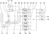
図1は本発明の第1に実施例に係る焦点調節装置を適用した像装置であるカメラの構成を示す図である。本撮像装置は、後述するように、結像光学系の射出瞳の瞳分割手段であるマイクロレンズアレイを有する撮像素子を有し、撮像面位相差方式の焦点調節が可能な装置である。
同図において、101は、被写体の光学像を生成する結像光学系の先端に配置された第1のレンズ群で、光軸方向に進退可能に保持される。102は絞り兼用シャッタで、その開口径を調節することで撮影時の光量調節を行なうほか、静止画撮影時には露光秒時調節用シャッタとしての機能も備える。103は第2のレンズ群である。そして前記絞り兼用シャッタ102及び第2のレンズ群103は一体となって光軸方向に進退し、前記第1のレンズ群101の進退動作との連動により、変倍作用(ズーム機能)を実現する。
[overall structure]
FIG. 1 is a diagram showing a configuration of a camera which is an image apparatus to which a focus adjusting apparatus according to a first embodiment of the present invention is applied. As will be described later, this imaging apparatus has an imaging element having a microlens array that is a pupil dividing means of an exit pupil of an imaging optical system, and is an apparatus capable of focus adjustment by an imaging plane phase difference method.
In the figure,
105は第3のレンズ群で、光軸方向の進退により、焦点調節を行なう。106は光学的ローパスフィルタで、撮影画像の偽色やモアレを軽減するための光学素子である。107は2次元CMOSフォトセンサーと周辺回路からなる撮像素子であり、結像光学系の結像面に配置される。
111はズームアクチュエータで、変倍作用を実現するために、不図示のカム筒を回動することで、第1のレンズ群111ないし第3レンズ群103を光軸方向に進退駆動する。し、変倍操作を行なう。112は絞りシャッタアクチュエータで、撮影光量を調節する絞り兼用シャッタ102の開口径を制御してと共に、静止画撮影時の露光時間制御を行なう。114はフォーカスアクチュエータで、焦点調節を行ため、第3のレンズ群105を光軸方向に進退駆動する。
115は撮影時の被写体照明用電子フラッシュで、キセノン管を用いた閃光照明装置が好適だが、連続発光するLEDを備えた照明装置を用いても良い。116はAF補助光手段で、所定の開口パターンを有したマスクの像を、投光レンズを介して被写界に投影し、暗い被写体あるいは低コントラスト被写体に対する焦点検出能力を向上させる。
121はCPUで、カメラ本体の種々の制御を司るカメラ内CPUで、演算部、ROM、RAM、A/Dコンバータ、D/Aコンバータ、通信インターフェイス回路等を有する。当該CPU121は、ROMに記憶された所定のプログラムをロードして実行することで、カメラが有する各種回路を駆動し、AF、撮影、画像処理と記録等の一連の動作を実行する。CPU121は本発明のする焦点調節装置を構成する手段であり、焦点調節のための信号処理を司る。
122は電子フラッシュ制御回路で、撮影動作に同期して照明手段115を点灯制御する。123は補助光駆動回路で、焦点検出動作に同期してAF補助光手段116を点灯制御する。124は撮像素子駆動回路で、撮像素子107の撮像動作を制御するとともに、取得した画像信号をA/D変換してCPU121に送信する。125は画像処理回路で、撮像素子107が生成した画像信号のγ変換、カラー補間、JPEG圧縮等の処理を行なう。
An electronic
126はフォーカス駆動回路で、焦点検出結果に基づいてフォーカスアクチュエータ114を駆動制御し、焦点調節を行うために第3のレンズ群105を光軸方向に進退駆動する。128は絞りシャッタ駆動回路で、絞りシャッタアクチュエータ112を駆動制御して絞り兼用シャッタ102の開口を制御する。129はズーム駆動回路で、撮影者のズーム操作に応じてズームアクチュエータ111を駆動する。
A
131はLCD等の表示装置で、カメラの撮影モードに関する情報、撮影前のプレビュー画像と撮影後の確認用画像、焦点検出時の合焦状態表示画像等を表示する。132は操作スイッチ群で、電源スイッチ、レリーズ(撮影トリガ)スイッチ、ズーム操作スイッチ、撮影モード選択スイッチ等で構成される。133は着脱可能なフラッシュメモリで、所定の記録フォーマットで記録部134により撮影済み画像が記録される。
[撮像素子]
本実施例の撮像装置が有する撮像素子の画素配列の概略を図2に示す。同図は、本実施例で用いられる撮像素子としての2次元CMOSセンサーの画素配列を、撮像画素の4列×4行の範囲(焦点検出画素の配列としては8列×4行の範囲)で示している。
[Image sensor]
FIG. 2 shows an outline of the pixel array of the image sensor included in the image pickup apparatus of the present embodiment. This figure shows a pixel array of a two-dimensional CMOS sensor as an image sensor used in the present embodiment in a range of 4 columns × 4 rows of image pickup pixels (a range of 8 columns × 4 rows as an array of focus detection pixels). Show.
本実施例において、図2に示した2列×2行の画素群200は、R(赤)の分光感度を有する画素200Rが図の左上の位置に、G(緑)の分光感度を有する画素200Gが右上と左下の位置に、B(青)の分光感度を有する画素200Bが右下の位置に配置されている。さらに、各画素は2列×1行に配列された第1の焦点検出画素201と第2の焦点検出画素202により構成されている。
In the present embodiment, the
撮像素子107は、図2に示す4列×4行の撮像画素(8列×4行の焦点検出画素)を撮像面上に多数配置し、撮像画像信号および焦点検出信号の取得を可能としている。本実施例では、画素の周期Pが4μm、画素数Nが横5575列×縦3725行=約2075万画素、焦点検出画素の列方向周期PAFが2μm、焦点検出画素数NAFが横11150列×縦3725行=約4150万画素の撮像素子として説明を行う。
The
図2に示す撮像素子の1つの画素200Gを、撮像素子の受光面側(+z側)から見た平面図を図3(a)に示し、図3(a)のa−a断面を−y側から見た断面図を図3(b)に示す。 A plan view of one pixel 200G of the image sensor shown in FIG. 2 as viewed from the light receiving surface side (+ z side) of the image sensor is shown in FIG. 3A, and the aa cross section of FIG. A cross-sectional view seen from the side is shown in FIG.
図3に示すように、本実施例の画素200Gでは、各画素の受光面に入射光を集光するためのマイクロレンズ305が形成され、x方向にNH分割(2分割)、y方向にNV分割(1分割)された光電変換部301と光電変換部302が形成される。光電変換部301と光電変換部302が、それぞれ、第1の焦点検出画素201と第2の焦点検出画素202に対応する。
As shown in FIG. 3, in the pixel 200G of the present embodiment, a
光電変換部301と光電変換部302は、p型層とn型層の間にイントリンシック層を挟んだpin構造フォトダイオードとしても良いし、必要に応じて、イントリンシック層を省略し、pn接合フォトダイオードとしても良い。
The
各画素には、マイクロレンズ305と、光電変換部301および光電変換部302との間に、カラーフィルター306が形成される。また、必要に応じて、副画素毎にカラーフィルターの分光透過率を変えても良いし、カラーフィルターを省略しても良い。
In each pixel, a
図3に示した画素200Gに入射した光は、マイクロレンズ305により集光され、カラーフィルター306で分光されたのち、光電変換部301と光電変換部302で受光される。
The light incident on the
光電変換部301と光電変換部302では、受光量に応じて電子とホールが対生成し、空乏層で分離された後、負電荷の電子はn型層(不図示)に蓄積され、一方、ホールは定電圧源(不図示)に接続されたp型層を通じて撮像素子外部へ排出される。
In the
光電変換部301と光電変換部302のn型層(不図示)に蓄積された電子は、転送ゲートを介して、静電容量部(FD)(不図示)に転送され、電圧信号に変換されて画素信号として出力される。
Electrons accumulated in the n-type layer (not shown) of the
図3に示した本実施例1の画素構造と瞳分割との光学的な対応関係を図4に示す。図3(a)に示した本実施例の画素構造のa−a断面を+y側から見た断面図と結像光学系の射出瞳面を示す。図4では、射出瞳面の座標軸と対応を取るために、断面図のx軸とy軸を図3に対して反転させている。なお、図4において、図3と同様の部分は同じ符号を付して示す。 FIG. 4 shows an optical correspondence between the pixel structure and pupil division of the first embodiment shown in FIG. FIG. 3A is a cross-sectional view of the pixel structure of the present embodiment shown in FIG. 3A as viewed from the + y side and shows the exit pupil plane of the imaging optical system. In FIG. 4, in order to correspond to the coordinate axis of the exit pupil plane, the x-axis and y-axis of the cross-sectional view are inverted with respect to FIG. In FIG. 4, the same parts as those in FIG. 3 are denoted by the same reference numerals.
図4に示すように、第1の焦点検出画素201の第1の瞳部分領域501は、重心が−x方向に偏心している光電変換部301の受光面と、マイクロレンズによって、概ね、共役関係になっており、第1の焦点検出画素201で受光可能な瞳領域を表している。第1の焦点検出画素201の第1の瞳部分領域501は、瞳面上で+X側に重心が偏心している。
As shown in FIG. 4, the first pupil partial region 501 of the first
また、第2の焦点検出画素202の第2の瞳部分領域402は、重心が+x方向に偏心している光電変換部302の受光面と、マイクロレンズによって、概ね、共役関係になっており、第2の焦点検出画素202で受光可能な瞳領域を表している。第2の焦点検出画素202の第2の瞳部分領域402は、瞳面上で−X側に重心が偏心している。
In addition, the second pupil
また、瞳領域400は、光電変換部301と光電変換部302(第1の焦点検出画素201と第2の焦点検出画素202)とを合わせた際の画素200G全体で受光可能な瞳領域である。
The
本実施例の撮像素子とマイクロレンズ(瞳分割手段)による瞳分割との対応関係の概略を図5に示す。射出瞳503の第1の瞳部分領域401と第2の瞳部分領域402の異なる瞳部分領域を通過した光束は、撮像素子の各画素に、それぞれ異なる角度で入射し、2×1分割された第1の焦点検出画素201と第2の焦点検出画素202で受光される。なお、本実施例では、瞳領域が水平方向に2つに瞳分割されている例を示しているが、必要に応じて、垂直方向に瞳分割を行っても良い。
FIG. 5 shows an outline of the correspondence between the image pickup element of this embodiment and pupil division by a microlens (pupil dividing means). Light beams that have passed through different pupil partial regions of the first pupil
上述のように、本実施例で用いる撮像素子は、結像光学系の異なる瞳部分領域を通過した被写体光をそれぞれ撮像可能な撮像手段である。例えば、結像光学系の第1の瞳部分領域を通過する被写体光を撮像する第1の焦点検出画素と、第1の瞳部分領域と異なる結像光学系の第2の瞳部分領域を通過する被写体光を撮像する第2の焦点検出画素とを有する。また、結像光学系の第1の瞳部分領域と第2の瞳部分領域を合わせた瞳領域を通過する光束を受光する撮像画素の配列も有することも可能である。なお、本実施例の撮像素子では、それぞれの撮像画素が第1の焦点検出画素と第2の焦点検出画素から構成されている。しかし、必要に応じて、撮像画素と第1の焦点検出画素および第2の焦点検出画素とを個別の画素構成とし、撮像画素配列の一部に、第1の焦点検出画素と第2の焦点検出画素を部分的に配置する構成としても良い。 As described above, the image pickup element used in the present embodiment is an image pickup unit that can pick up the subject light that has passed through different pupil partial regions of the imaging optical system. For example, the first focus detection pixel that captures the subject light passing through the first pupil partial region of the imaging optical system and the second pupil partial region of the imaging optical system different from the first pupil partial region And a second focus detection pixel that images the subject light to be captured. It is also possible to have an array of imaging pixels that receive a light beam that passes through a pupil region that is a combination of the first pupil partial region and the second pupil partial region of the imaging optical system. In the imaging device of this embodiment, each imaging pixel is composed of a first focus detection pixel and a second focus detection pixel. However, if necessary, the imaging pixel, the first focus detection pixel, and the second focus detection pixel are configured as separate pixels, and the first focus detection pixel and the second focus are included in a part of the imaging pixel array. A configuration may be adopted in which the detection pixels are partially arranged.
本実施例では、撮像素子の各画素の第1の焦点検出画素201の受光信号を集めて第1の焦点検出信号を生成し、各画素の第2の焦点検出画素202の画素信号を集めて第2の焦点検出信号を生成(信号生成手段)して焦点検出を行う。また、撮像素子の画素毎に、第1の焦点検出画素201と第2の焦点検出画素202の信号を加算することで、有効画素数Nの解像度の撮像信号(撮像画像)を生成する。
In this embodiment, the light reception signals of the first
[デフォーカス量と像ずれ量の関係]
次に、本実施例で用いる撮像素子により取得される第1の焦点検出信号と第2の焦点検出信号の像ずれ量とデフォーカス量との関係について説明する。
[Relationship between defocus amount and image shift amount]
Next, the relationship between the image shift amount and the defocus amount of the first focus detection signal and the second focus detection signal acquired by the image sensor used in this embodiment will be described.
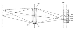
図6に、第1の焦点検出信号と第2の焦点検出信号のデフォーカス量と第1の焦点検出信号と第2の焦点検出信号間の像ずれ量の関係の概略を示す。撮像面500に本実施例で用いる撮像素子(不図示)が配置され、図4、図5と同様に、結像光学系の射出瞳が、第1の瞳部分領域401と第2の瞳部分領域402に2分割される。なお、図6において図3乃至5と同様の部分は同じ符号を付して示す。
FIG. 6 shows an outline of the relationship between the defocus amounts of the first focus detection signal and the second focus detection signal and the image shift amount between the first focus detection signal and the second focus detection signal. An imaging element (not shown) used in the present embodiment is arranged on the
デフォーカス量dは、被写体の結像位置から撮像面500までの距離を大きさ|d|としとき、被写体の結像位置が撮像面より被写体側にある前ピン状態を負符号(d<0)、撮像面500より被写体の反対側にある後ピン状態を正符号(d>0)として定義される。被写体の結像位置が撮像面500(合焦位置)にある合焦状態はd=0である。図6で、被写体601は合焦状態(d=0)の例を示しており、被写体602は前ピン状態(d<0)の例を示している。前ピン状態(d<0)と後ピン状態(d>0)を合わせて、デフォーカス状態(|d|>0)とする。
The defocus amount d is a negative sign (d <0) when the distance from the imaging position of the subject to the
前ピン状態(d<0)では、被写体602からの光束のうち、第1の瞳部分領域401(第2の瞳部分領域402)を通過した被写体光は、一度、集光した後、光束の重心位置G1(G2)を中心として幅Γ1(Γ2)に広がり、撮像面500でボケた像となる。ボケた像は、撮像素子に配列された各画素を構成する第1の焦点検出画素201(第2の焦点検出画素202)により受光され、第1の焦点検出信号(第2の焦点検出信号)が生成される。よって、第1の焦点検出信号(第2の焦点検出信号)は、撮像面500上の重心位置G1(G2)に、被写体602が幅Γ1(Γ2)にボケた被写体像として記録される。被写体像のボケ幅Γ1(Γ2)は、デフォーカス量dの大きさ|d|が増加するのに伴い、概ね、比例して増加していく。同様に、第1の焦点検出信号と第2の焦点検出信号間の被写体像の像ずれ量p(=光束の重心位置の差G1−G2)の大きさ|p|も、デフォーカス量dの大きさ|d|が増加するのに伴い、概ね、比例して増加していく。後ピン状態(d>0)でも、第1の焦点検出信号と第2の焦点検出信号間の被写体像の像ずれ方向が前ピン状態と反対となるが、同様である。
In the front pin state (d <0), the subject light that has passed through the first pupil partial region 401 (second pupil partial region 402) out of the light flux from the subject 602 is condensed once and then the light flux The image expands in the width Γ1 (Γ2) with the center of gravity G1 (G2) as the center, resulting in a blurred image on the
よって、本発明では、第1の焦点検出信号と第2の焦点検出信号、もしくは、第1の焦点検出信号と第2の焦点検出信号を加算した撮像信号のデフォーカス量の大きさが増加するのに伴い、第1の焦点検出信号と第2の焦点検出信号間の像ずれ量の大きさが増加する。 Therefore, in the present invention, the magnitude of the defocus amount of the first focus detection signal and the second focus detection signal or the imaging signal obtained by adding the first focus detection signal and the second focus detection signal increases. Accordingly, the amount of image shift between the first focus detection signal and the second focus detection signal increases.
本実施例では、第1の焦点検出信号と第2の焦点検出信号のデフォーカス量と像ずれ量の関係性を用いて、位相差方式の焦点調節を行う。 In this embodiment, phase difference type focus adjustment is performed using the relationship between the defocus amount and the image shift amount of the first focus detection signal and the second focus detection signal.
位相差方式の焦点調節は、第1の焦点検出信号と第2の焦点検出信号を相対的にシフトさせて信号の一致度を表す相関量を計算し、相関(信号の一致度)が良くなるシフト量から像ずれ量を検出する。撮像信号のデフォーカス量の大きさが増加するのに伴い、第1の焦点検出信号と第2の焦点検出信号間の像ずれ量の大きさが増加する関係性から、像ずれ量をデフォーカス量に変換することで焦点検出を行う。 In the phase difference type focus adjustment, the first focus detection signal and the second focus detection signal are relatively shifted to calculate a correlation amount indicating the degree of coincidence of signals, and the correlation (the degree of coincidence of signals) is improved. An image shift amount is detected from the shift amount. As the defocus amount of the imaging signal increases, the image shift amount is defocused because of the relationship that the image shift amount increases between the first focus detection signal and the second focus detection signal. Focus detection is performed by converting to a quantity.
[枠ケラレ]
本実施例では、撮像素子のマイクロレンズを利用して瞳分割するため、回折の影響により瞳分割領域が明瞭な領域とならず受光率分布となり、撮像レンズのレンズ枠や絞り枠により枠ケラレが生じる。
[Frame vignetting]
In this embodiment, the pupil division is performed using the microlens of the image sensor, so that the pupil division area does not become a clear area due to the influence of diffraction, and the light receiving rate distribution is obtained, and the frame vignetting is caused by the lens frame and the diaphragm frame of the imaging lens. Arise.
図4で、射出瞳面までの瞳距離が数10mmであるのに対し、マイクロレンズの直径は数μmである。そのため、マイクロレンズの絞り値が数万となり、数10mmレベルの回折ボケが生じる。よって、光電変換部の受光面の像は、明瞭な瞳領域や瞳部分領域とはならずに、瞳強度分布(受光率の入射角分布)となる。 In FIG. 4, the pupil distance to the exit pupil plane is several tens of mm, whereas the diameter of the microlens is several μm. For this reason, the aperture value of the microlens becomes several tens of thousands, and diffraction blur of several tens mm level occurs. Therefore, the image of the light receiving surface of the photoelectric conversion unit is not a clear pupil region or pupil partial region, but a pupil intensity distribution (incident angle distribution of light reception rate).
図4の結像光学系の射出瞳面のX軸に対して第1の焦点検出画素の第1の瞳部分領域401を射影した第1の焦点検出画素のX軸に沿った1次元の瞳強度分布の例を図7(点線)で示す。また、図4の結像光学系の射出瞳面のX軸に第2の焦点検出画素の第2の瞳部分領域402を射影した第2の焦点検出画素のX軸に沿った1次元の瞳強度分布の例を図7(実線)で示す。図7の横軸は、結像光学系の射出瞳面のX軸で、縦軸は受光率である。
A one-dimensional pupil along the X axis of the first focus detection pixel, which is obtained by projecting the first pupil
図7の第1の焦点検出画素の瞳強度分布(点線)の−X側は、マイクロレンズによる瞳分割のため、瞳部分領域の境界が回折の影響でボヤけ、緩やかな曲線となる。一方反対の+X側は、結像光学系のレンズ枠や絞り枠で規定される射出瞳によりケラレるため、急峻な曲線となる。一方、図7の第2の焦点検出画素の瞳強度分布(実線)は、第1の焦点検出画素の瞳強度分布(点線)のX軸の正負を反転した形となる。よって、第1の焦点検出画素の瞳強度分布と第2の焦点検出画素の瞳強度分布は同形状ではなく、平行移動(シフト)して重ね合わせた場合の一致度が低下する。 On the −X side of the pupil intensity distribution (dotted line) of the first focus detection pixel in FIG. 7, the boundary of the pupil partial area is blurred due to the influence of diffraction due to the pupil division by the microlens and becomes a gentle curve. On the other hand, the opposite + X side has a steep curve because it is vignetted by the exit pupil defined by the lens frame and diaphragm frame of the imaging optical system. On the other hand, the pupil intensity distribution (solid line) of the second focus detection pixel in FIG. 7 has a shape obtained by inverting the positive / negative of the X axis of the pupil intensity distribution (dotted line) of the first focus detection pixel. Therefore, the pupil intensity distribution of the first focus detection pixel and the pupil intensity distribution of the second focus detection pixel are not the same shape, and the degree of coincidence is reduced when they are translated (shifted) and overlapped.
図7の第1の焦点検出画素と第2の焦点検出画素の1次元の瞳強度分布を、結像光学系の瞳距離とデフォーカス量に応じてスケール変換したものが、それぞれ、第1の焦点検出信号と第2の焦点検出信号の線像となる。したがって、デフォーカス状態では、第1の焦点検出信号の線像と第2の焦点検出信号の線像は同形状ではなく、第1の焦点検出信号と第2の焦点検出信号の同形性が崩れる。合焦状態では、第1の焦点検出信号の線像と第2の焦点検出信号の線像が共にデルタ関数に近づき、第1の焦点検出信号と第2の焦点検出信号が概ね同形状となる。 The one-dimensional pupil intensity distribution of the first focus detection pixel and the second focus detection pixel in FIG. 7 is scale-converted according to the pupil distance and defocus amount of the imaging optical system, respectively. A line image of the focus detection signal and the second focus detection signal is obtained. Therefore, in the defocus state, the line image of the first focus detection signal and the line image of the second focus detection signal are not the same shape, and the isomorphism of the first focus detection signal and the second focus detection signal is lost. . In the in-focus state, both the line image of the first focus detection signal and the line image of the second focus detection signal approach the delta function, and the first focus detection signal and the second focus detection signal have substantially the same shape. .
本実施例での2本線被写体の第1の焦点検出信号(破線)と第2の焦点検出信号(実線)の合焦状態での例を図8(a)に、中デフォーカス状態での例を図8(b)に、大デフォーカス状態での例を図8(c)に示す。合焦状態から大デフォーカス状態になるにつれて、ボケながら像ずれ量が増加することがわかる。 An example in the focused state of the first focus detection signal (broken line) and the second focus detection signal (solid line) of the two-line subject in this embodiment is shown in FIG. FIG. 8B shows an example in a large defocus state, and FIG. It can be seen that the amount of image shift increases as the focus state shifts to a large defocus state.
位相差方式の焦点調節では、通常、相関(信号の一致度)を良くして焦点検出精度を向上するために、第1の焦点検出信号と第2の焦点検出信号のDC成分をカットしてエッジ抽出を行う差分型フィルター(第1のフィルター)の処理を施した後、相関量を算出する。差分型フィルターは、{1、2、0、−2、−1}や{1、4、4、4、0、−4、−4、−4、−1}の例のように、フィルター成分が正と負の値から構成される。 In the phase difference type focus adjustment, the DC components of the first focus detection signal and the second focus detection signal are usually cut in order to improve the correlation (degree of signal coincidence) and improve the focus detection accuracy. After performing a differential filter (first filter) for performing edge extraction, a correlation amount is calculated. The differential filter is a filter component such as {1, 2, 0, -2, -1} or {1, 4, 4, 4, 0, -4, -4, -4, -1}. Consists of positive and negative values.
図8(a)の合焦状態の第1の焦点検出信号(破線)と第2の焦点検出信号(実線)に差分型フィルター処理を施した例を図8(d)に示す。また、図8(b)の中デフォーカス状態の第1の焦点検出信号(破線)と第2の焦点検出信号(実線)に差分型フィルター処理を施した例を図8(e)に示す。 FIG. 8D shows an example in which differential filter processing is performed on the first focus detection signal (broken line) and the second focus detection signal (solid line) in the focused state in FIG. FIG. 8E shows an example in which differential filter processing is performed on the first focus detection signal (broken line) and the second focus detection signal (solid line) in the defocused state in FIG. 8B.
しかしながら、枠ケラレにより同形性が崩れた第1の焦点検出信号と第2の焦点検出信号に、エッジ抽出を行う差分型(第1の)フィルター処理を施すと、撮影条件によって、第1の焦点検出信号と第2の焦点検出信号の形状の歪みが強調されることがある。その結果、誤った合焦(偽合焦)検出をしてしまう場合がある。 However, if the first focus detection signal and the second focus detection signal whose isomorphism has been lost due to frame vignetting are subjected to differential (first) filter processing for edge extraction, the first focus detection signal may vary depending on the shooting conditions. The distortion of the shape of the detection signal and the second focus detection signal may be emphasized. As a result, erroneous focus (false focus) may be detected.
図8(c)の大デフォーカス状態の第1の焦点検出信号(破線)と第2の焦点検出信号(実線)に差分型フィルター処理を施した例を図8(f)に示す。図8(f)は、差分型フィルター処理を施すことにより、第1の焦点検出信号と第2の焦点検出信号の形状の歪みが強調され、偽合焦検出をしてしまう場合の信号例である。図8(e)のデフォーカス量よりも、図8(f)のデフォーカス量の方が大きいにもかかわらず、第1の焦点検出信号と第2の焦点検出信号の形状の歪みが強調された結果、図8(f)のデフォーカス量が小さく算出され、偽合焦検出となる例である。 FIG. 8F shows an example in which differential filter processing is performed on the first focus detection signal (broken line) and the second focus detection signal (solid line) in the large defocus state in FIG. 8C. FIG. 8F shows an example of a signal when the distortion of the shapes of the first focus detection signal and the second focus detection signal is enhanced by performing the differential filter process, and false focus detection is performed. is there. Although the defocus amount in FIG. 8F is larger than the defocus amount in FIG. 8E, the distortion of the shapes of the first focus detection signal and the second focus detection signal is emphasized. As a result, the defocus amount in FIG. 8F is calculated to be small and false focus detection is performed.
図8(f)のように差分型フィルター処理により偽合焦検出となる場合は、図8(c)のように差分型フィルター処理を行わずに相関量を演算し、デフォーカス量を算出することで、合焦か偽合焦か判定することができる。 When false focus detection is performed by differential filter processing as illustrated in FIG. 8F, the correlation amount is calculated without performing differential filter processing as illustrated in FIG. 8C, and the defocus amount is calculated. Thus, it is possible to determine whether it is in focus or false focus.
差分型フィルター処理を行わない場合は、第1の焦点検出信号と第2の焦点検出信号の高周波ノイズ成分を抑制する加算型フィルター(第2のフィルター)の処理を施した後、相関量を算出する。加算型フィルターは、{1、1}や{1、2、1}の例のように、フィルター成分が全て非負(正または0)のみの値、もしくは、全て非正(負または0)のみの値から構成される。 When differential filter processing is not performed, the amount of correlation is calculated after processing of an addition filter (second filter) that suppresses high-frequency noise components of the first focus detection signal and the second focus detection signal. To do. As in the example of {1, 1} and {1, 2, 1}, the addition type filter has all non-negative (positive or 0) filter components, or all non-positive (negative or 0) only. Consists of values.
[焦点検出]
本発明では、第1の焦点検出信号と第2の焦点検出信号に差分型フィルター処理を行い、第1の相関量を算出して焦点検出を行う際に、第1の焦点検出信号と第2の焦点検出信号に加算型フィルター処理を行い、第2の相関量を算出して偽合焦判定を行う。これにより、第1の相関量に基づく焦点検出における偽合焦検出を抑制し、焦点検出精度を向上することができる。
[Focus detection]
In the present invention, when the first focus detection signal and the second focus detection signal are subjected to differential filter processing to calculate the first correlation amount and perform focus detection, the first focus detection signal and the second focus detection signal are output. The focus detection signal is subjected to addition type filter processing, a second correlation amount is calculated, and false focus determination is performed. Thereby, false focus detection in focus detection based on the first correlation amount can be suppressed, and focus detection accuracy can be improved.
図9に、本実施例の焦点調節動作のフローチャートを示す。なお、図9の動作は、本実施例における撮像装置の撮像素子107、画像処理回路125およびCPU121によって実行される。特に、本実施例に係る焦点調節装置の焦点検出信号生成手段、第1の相関量生成手段、第2の相関量生成手段、第1の焦点検出手段、および評価値生成手段としての機能は、画像処理回路125およびCPU121によって実行される。
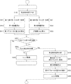
FIG. 9 shows a flowchart of the focus adjustment operation of this embodiment. The operation of FIG. 9 is executed by the
ステップS100で、焦点検出信号生成手段により、第1の焦点検出信号と第2の焦点検出信号を生成する。ここで、ステップS100における第1の焦点検出信号と第2の焦点検出信号の生成動作を図10に示すフローチャートを用いて説明する。 In step S100, the focus detection signal generation unit generates a first focus detection signal and a second focus detection signal. Here, the generation operation of the first focus detection signal and the second focus detection signal in step S100 will be described using the flowchart shown in FIG.
ステップS101で、撮像素子の有効な画素領域の中から焦点調節を行う焦点検出領域を設定する。焦点検出信号生成手段により、焦点検出領域の第1の焦点検出画素の画素信号から第1の焦点検出信号を生成し、焦点検出領域の第2の焦点検出画素の画素信号から第2の焦点検出信号を生成する。 In step S101, a focus detection area for performing focus adjustment is set from the effective pixel areas of the image sensor. The focus detection signal generating means generates a first focus detection signal from the pixel signal of the first focus detection pixel in the focus detection area, and the second focus detection from the pixel signal of the second focus detection pixel in the focus detection area. Generate a signal.
ステップS102で、第1の焦点検出信号と第2の焦点検出信号に、それぞれ、信号データ量を抑制するために列方向に3画素加算処理を行い、さらに、RGB信号を輝度Y信号にするためにベイヤー(RGB)加算処理を行う。これら2つの加算処理を合わせて第1の画素加算処理とする。 In step S102, the first focus detection signal and the second focus detection signal are each subjected to a three-pixel addition process in the column direction in order to suppress the amount of signal data, and further, the RGB signal is converted into a luminance Y signal. The Bayer (RGB) addition process is performed on These two addition processes are combined to form a first pixel addition process.
ステップS103では、第1の焦点検出信号と第2の焦点検出信号に、それぞれ、焦点検出領域の像高と、撮影像レンズ(結像光学系)のF値および射出瞳距離に応じてシェーディング補正処理(光学補正処理)を行う。 In step S103, shading correction is performed on the first focus detection signal and the second focus detection signal according to the image height of the focus detection area, the F value of the photographic image lens (imaging optical system), and the exit pupil distance, respectively. Processing (optical correction processing) is performed.
図9のステップS011では、第1の焦点検出信号と第2の焦点検出信号に、DC成分をカットしてエッジ抽出を行う正負成分を有する差分型フィルター処理を行う。本実施例1の差分型フィルターの通過帯域の例を、図11に実線で示す。 In step S011 in FIG. 9, the first focus detection signal and the second focus detection signal are subjected to differential filter processing having positive and negative components that perform edge extraction by cutting the DC component. An example of the pass band of the differential filter of the first embodiment is shown by a solid line in FIG.
ステップS012では、第1の相関量算出手段により、差分型フィルター処理後の第1の焦点検出信号と第2の焦点検出信号を相対的に瞳分割方向にシフトさせるシフト処理を行い、信号の一致度を表す第1の相関量を算出する。 In step S012, the first correlation amount calculation means performs a shift process for relatively shifting the first focus detection signal and the second focus detection signal after the differential filter processing in the pupil division direction, thereby matching the signals. A first correlation amount representing the degree is calculated.
k番目の第1の焦点検出信号をA(k)、第2の焦点検出信号をB(k)、焦点検出領域に対応する番号kの範囲をWとする。シフト処理によるシフト量をs、シフト量sのシフト範囲をΓとして、第1の相関量CORは、式(1)により算出される。

シフト量sのシフト処理により、k番目の第1の焦点検出信号A(k)とk−s番目の第2の焦点検出信号B(k−s)を対応させ減算し、シフト減算信号を生成する。焦点検出領域に対応する範囲W内で番号kについて、生成されたシフト減算信号の絶対値の和を取り、第1の相関量COR(s)を算出する。なお、必要に応じて、各行毎に算出された第1の相関量を、各シフト量毎に、複数行に渡って加算しても良い。 By shifting the shift amount s, the k-th first focus detection signal A (k) and the ks-th second focus detection signal B (ks) are subtracted to generate a shift subtraction signal. To do. The first correlation amount COR (s) is calculated by taking the sum of the absolute values of the generated shift subtraction signals for the number k within the range W corresponding to the focus detection area. If necessary, the first correlation amount calculated for each row may be added over a plurality of rows for each shift amount.
ステップS013では、第1の焦点検出手段により、第1の相関量から、サブピクセル演算により、第1の相関量が最小値となる実数値のシフト量を算出して第1の像ずれ量p1とする。第1の像ずれ量p1に、焦点検出領域の像高と、撮影レンズ(結像光学系)のF値、射出瞳距離に応じた変換係数Kをかけて、第1のデフォーカス量(Def1)を検出する。 In step S013, the first focus detection unit calculates a real-valued shift amount at which the first correlation amount is the minimum value from the first correlation amount by the sub-pixel calculation, thereby calculating the first image shift amount p1. And The first defocus amount (Def1) is obtained by multiplying the first image shift amount p1 by the image height of the focus detection region, the F value of the photographing lens (imaging optical system), and the conversion coefficient K corresponding to the exit pupil distance. ) Is detected.
本実施例では、第1の焦点検出信号と第2の焦点検出信号に、正負成分を有する差分型の第1のフィルターを用いてフィルター処理を行って第1の相関量を算出し、第1の相関量から第1のデフォーカス量を検出する。 In the present embodiment, the first focus detection signal and the second focus detection signal are filtered using a differential first filter having positive and negative components to calculate a first correlation amount, The first defocus amount is detected from the correlation amount.
図9のステップS014では、第1のデフォーカス量(Def1)の絶対値が所定値1より大きいかどうかを判定し、大きい場合は、結像光学系の焦点状態がデフォーカス状態であると判定し、ステップS200に進む。第1のデフォーカス量(Def1)の絶対値が第1の所定値以下の場合は、結像光学系の焦点状態が合焦状態(合焦位置近傍)の可能性があると判定し、ステップS100で、第1の焦点検出信号と第2の焦点検出信号を生成する。その後、偽合焦であるかどうかを判定するためにステップS021に進む。
In step S014 of FIG. 9, it is determined whether or not the absolute value of the first defocus amount (Def1) is larger than a
ステップS021では、第1の焦点検出信号と第2の焦点検出信号に、高周波ノイズ成分を抑制する非負成分のみ、もしくは、非正成分のみを有する加算型フィルター(第2のフィルター)処理を行う。 In step S021, the first focus detection signal and the second focus detection signal are subjected to addition type filter (second filter) processing having only a non-negative component that suppresses high-frequency noise components or only a non-positive component.
ステップS022では、第2の相関量算出手段により、加算型フィルター処理後の第1の焦点検出信号と第2の焦点検出信号を相対的に瞳分割方向にシフトさせるシフト処理を行い、信号の一致度を表す第2の相関量を算出する。第2の相関量の算出は、第1の焦点検出信号と第2の焦点検出信号に差分型フィルター処理ではなく加算型フィルター処理を施す以外は、第1の相関量の算出と同様である。 In step S022, the second correlation amount calculation means performs a shift process for relatively shifting the first focus detection signal and the second focus detection signal after the addition filter processing in the pupil division direction, thereby matching the signals. A second correlation amount representing the degree is calculated. The calculation of the second correlation amount is the same as the calculation of the first correlation amount except that the first focus detection signal and the second focus detection signal are subjected to the addition type filter processing instead of the difference type filter processing.
ステップS023では、評価値算出手段により、第2の相関量から評価値(Obj)を算出する。本実施例では、第2の相関量からサブピクセル演算により、第2の相関量が最小値となる実数値のシフト量を算出して第2の像ずれ量p2を算出する。次に、算出された像ずれ量p2に、焦点検出領域の像高と、撮像レンズ(結像光学系)のF値、射出瞳距離に応じた変換係数Kをかけて、第2のデフォーカス量(Def2)を算出する。第2のデフォーカス量(Def2)の絶対値を、評価値(Obj)とする。 In step S023, an evaluation value (Obj) is calculated from the second correlation amount by the evaluation value calculation means. In the present embodiment, the second image shift amount p2 is calculated by calculating a real-valued shift amount that minimizes the second correlation amount from the second correlation amount by sub-pixel calculation. Next, the calculated image shift amount p2 is multiplied by the image height of the focus detection area, the F value of the imaging lens (imaging optical system), and the conversion coefficient K corresponding to the exit pupil distance, so that the second defocusing is performed. The amount (Def2) is calculated. The absolute value of the second defocus amount (Def2) is set as an evaluation value (Obj).
なお、必要に応じて、第2の相関量からサブピクセル演算により計算された第2の相関量の最小値(像一致度)を評価値(Obj)としても良い。第1の焦点検出信号と第2の焦点検出信号の形状一致度が良くなるほど、第2の相関量の最小値(像一致度)が小さくなる。また、必要に応じて、算出された第2の像ずれ量p2の位置での第2の相関量の傾き(第2の相関量の1階微分)の逆数を評価値(Obj)としても良い。 If necessary, the minimum value (image matching degree) of the second correlation amount calculated from the second correlation amount by subpixel calculation may be used as the evaluation value (Obj). The better the shape matching degree between the first focus detection signal and the second focus detection signal, the smaller the minimum value (image matching degree) of the second correlation amount. If necessary, the evaluation value (Obj) may be the reciprocal of the slope of the second correlation amount (the first derivative of the second correlation amount) at the position of the calculated second image shift amount p2. .
このように本実施例では、第1の焦点検出信号と第2の焦点検出信号に、非負成分のみ、もしくは、非正成分のみを有する加算型の第2のフィルターを用いてフィルター処理を行って第2の相関量を算出し、第2の相関量から評価値を算出する。 As described above, in this embodiment, the first focus detection signal and the second focus detection signal are subjected to filter processing using the addition type second filter having only the non-negative component or only the non-positive component. A second correlation amount is calculated, and an evaluation value is calculated from the second correlation amount.
図9のステップS024で、評価値(Obj)が第2の所定値より大きいかどうかを判定し、大きい場合は、結像光学系の焦点状態が合焦位置近傍ではなく、デフォーカス状態であると評価し、ステップS200に進む。ステップS200では、第1のデフォーカス量(Def1)に応じて、結像光学系のレンズ駆動を行い、再び、ステップS100で、第1の焦点検出信号と第2の焦点検出信号を生成した後、ステップS011に進む。 In step S024 in FIG. 9, it is determined whether or not the evaluation value (Obj) is larger than the second predetermined value. If the evaluation value (Obj) is larger, the focus state of the imaging optical system is not in the vicinity of the focus position but in the defocus state. And the process proceeds to step S200. In step S200, the lens of the imaging optical system is driven according to the first defocus amount (Def1), and after generating the first focus detection signal and the second focus detection signal again in step S100. The process proceeds to step S011.
図9のステップS024で、評価値(Obj)が第2の所定値以下の場合は、結像光学系の焦点状態が合焦状態(合焦位置近傍)であると評価し、焦点調節動作を終了する。 If the evaluation value (Obj) is equal to or smaller than the second predetermined value in step S024 in FIG. 9, it is evaluated that the focus state of the imaging optical system is the focus state (near the focus position), and the focus adjustment operation is performed. finish.
本発明では、第1の相関量から算出された第1のデフォーカス量の絶対値が第1の所定値以下の場合、第2の相関量から算出された評価値に基づき第1のデフォーカス量の偽合焦判定を行う。 In the present invention, when the absolute value of the first defocus amount calculated from the first correlation amount is equal to or smaller than the first predetermined value, the first defocus is based on the evaluation value calculated from the second correlation amount. Make a false focus determination of the amount.
第1の焦点検出信号や第2の焦点検出信号が低コントラストの場合は、DC成分を含む第2の相関量から算出された評価値の信頼性が低下することがある。よって、必要に応じて、第1の焦点検出信号と第2の焦点検出信号が低コントラストの場合は、第2の相関量から算出された評価値に基づく第1のデフォーカス量の偽合焦判定を行わないように、条件分岐を行っても良い。 When the first focus detection signal and the second focus detection signal have low contrast, the reliability of the evaluation value calculated from the second correlation amount including the DC component may be reduced. Therefore, if necessary, when the first focus detection signal and the second focus detection signal have low contrast, the false defocusing of the first defocus amount based on the evaluation value calculated from the second correlation amount Conditional branching may be performed so that the determination is not performed.
なお、第1の焦点検出信号{A(k)、k∈W}のコントラスト評価値としては、画素信号の最大値と最小値との差、隣接差分の絶対値の和Σ|A(k+1)−A(k)|、隣接差分の絶対値の2乗和Σ|A(k+1)−A(k)|^2などを用いることができる。第2の焦点検出信号についても同様である。第1の焦点検出信号や第2の焦点検出信号のコントラスト評価値が第3の所定値以下の場合に低コントラストであると判定することができる。 Note that the contrast evaluation value of the first focus detection signal {A (k), kεW} is the difference between the maximum value and the minimum value of the pixel signal and the sum of absolute values of adjacent differences Σ | A (k + 1) −A (k) |, square sum of absolute values of adjacent differences Σ | A (k + 1) −A (k) | ^ 2, and the like can be used. The same applies to the second focus detection signal. When the contrast evaluation value of the first focus detection signal or the second focus detection signal is equal to or lower than the third predetermined value, it can be determined that the contrast is low.
以上の構成により、撮像面位相差方式の焦点調節において、偽合焦検出を抑制し、焦点検出精度を向上することが可能となる。 With the above configuration, it is possible to suppress false focus detection and improve focus detection accuracy in focus adjustment using the imaging surface phase difference method.
次に、本発明の第2の実施例の焦点調節動作を図12に示すフローチャートを用いて説明する。本実施例は、第1の焦点検出信号と第2の焦点検出信号に差分型フィルター処理を行う第1の相関量の算出と、加算型フィルター処理を行う第2の相関量の算出とを並列処理して高速に焦点調節を行う例である。なお、撮像装置については第1の実施例と同様であるためここでの説明は省略する。また、図12において、図9と同様の部分は同じ符号を付して示す。 Next, the focus adjustment operation of the second embodiment of the present invention will be described with reference to the flowchart shown in FIG. In the present embodiment, the calculation of the first correlation amount for performing the difference type filter processing on the first focus detection signal and the second focus detection signal and the calculation of the second correlation amount for performing the addition type filter processing are performed in parallel. This is an example of processing and performing high-speed focus adjustment. Since the imaging apparatus is the same as that of the first embodiment, the description thereof is omitted here. In FIG. 12, the same parts as those in FIG. 9 are denoted by the same reference numerals.
図12のステップS100で、焦点検出信号生成手段により、第1の焦点検出信号と第2の焦点検出信号を生成し、ステップS011とステップS021に、それぞれ、進む。 In step S100 of FIG. 12, the focus detection signal generation unit generates a first focus detection signal and a second focus detection signal, and proceeds to step S011 and step S021, respectively.
図12のステップS011からステップS013では、第1の実施例と同様に、第1の焦点検出信号と第2の焦点検出信号に、正負成分を有する差分型の第1のフィルターを用いてフィルター処理を行い、第1の相関量を算出する。そして、第1の相関量から第1のデフォーカス量(Def1)を検出する。 In step S011 to step S013 of FIG. 12, similarly to the first embodiment, the first focus detection signal and the second focus detection signal are filtered using a differential first filter having positive and negative components. To calculate a first correlation amount. Then, the first defocus amount (Def1) is detected from the first correlation amount.
また、図12のステップS021からステップS023では、第1の実施例と同様に、第1の焦点検出信号と第2の焦点検出信号に、非負成分のみ、もしくは非正成分のみを有する加算型の第2のフィルターを用いてフィルター処理を行う。そして、処理された焦点検出信号から第2の相関量を算出し、第2の相関量から評価値(Obj)を算出する。 Also, in steps S021 to S023 of FIG. 12, as in the first embodiment, the first focus detection signal and the second focus detection signal include only non-negative components or non-positive components. Filtering is performed using the second filter. Then, a second correlation amount is calculated from the processed focus detection signal, and an evaluation value (Obj) is calculated from the second correlation amount.
図12のステップS014では、第1のデフォーカス量(Def1)の絶対値が第1の所定値より大きいかどうかを判定し、大きい場合は、結像光学系の焦点状態がデフォーカス状態であると判定し、ステップS200に進む。第1のデフォーカス量(Def1)の絶対値が第1の所定値以下の場合は、結像光学系の焦点状態が合焦状態(合焦位置近傍)の可能性があると判定し、ステップS024に進む。 In step S014 in FIG. 12, it is determined whether or not the absolute value of the first defocus amount (Def1) is larger than the first predetermined value. If the absolute value is larger, the focus state of the imaging optical system is the defocus state. And the process proceeds to step S200. If the absolute value of the first defocus amount (Def1) is less than or equal to the first predetermined value, it is determined that the focus state of the imaging optical system may be in focus (near the focus position), and step The process proceeds to S024.
図12のステップS024で、評価値(Obj)が第2の所定値より大きい場合は、結像光学系の焦点状態が合焦位置近傍ではなく、デフォーカス状態であると評価し、ステップS200に進む。ステップS200では、第1のデフォーカス量(Def1)に応じて、結像光学系のレンズ駆動を行い、再び、ステップS100で第1の焦点検出信号と第2の焦点検出信号を生成した後、ステップS011とステップS021に、それぞれ、進む。 If the evaluation value (Obj) is larger than the second predetermined value in step S024 in FIG. 12, it is evaluated that the focus state of the imaging optical system is not near the in-focus position but in the defocus state, and the process proceeds to step S200. move on. In step S200, the lens of the imaging optical system is driven according to the first defocus amount (Def1), and after generating the first focus detection signal and the second focus detection signal again in step S100, The process proceeds to step S011 and step S021, respectively.
図12のステップS024で、評価値(Obj)が所定値2以下の場合は、結像光学系の焦点状態が合焦状態(合焦位置近傍)であると評価し、ステップS100で、第1の焦点検出信号と第2の焦点検出信号を生成した後、ステップS031に進む。
If the evaluation value (Obj) is equal to or smaller than the
ステップS031では、結像光学系の合焦位置近傍のため、第1の焦点検出信号と第2の焦点検出信号に、差分型フィルターよりも高周波の通過帯域を有する差分型ハイパスフィルター(第3のフィルター)処理を行う。本実施例の差分型ハイパスフィルターの通過帯域の例を、図11の一点鎖線、破線、点線で示す。 In step S031, because of the vicinity of the focus position of the imaging optical system, the first focus detection signal and the second focus detection signal have a differential high-pass filter (third Filter) process. Examples of the pass band of the differential high-pass filter of the present embodiment are indicated by a one-dot chain line, a broken line, and a dotted line in FIG.
ステップS032では、第3相関量算出手段により、差分型ハイパスフィルター処理後の第1の焦点検出信号と第2の焦点検出信号を相対的に瞳分割方向にシフトさせるシフト処理を行い、信号の一致度を表す第3相関量を算出する。第3相関量の算出は、第1の焦点検出信号と第2の焦点検出信号に差分型フィルター処理ではなく差分型ハイパスフィルター処理を施す以外は、第1の相関量の算出と同様である。 In step S032, the third correlation amount calculation means performs a shift process for relatively shifting the first focus detection signal and the second focus detection signal after the differential high-pass filter processing in the pupil division direction, thereby matching the signals. A third correlation amount representing the degree is calculated. The calculation of the third correlation amount is the same as the calculation of the first correlation amount except that the first focus detection signal and the second focus detection signal are subjected to differential high-pass filter processing instead of differential filter processing.
ステップS033では、第1の焦点検出手段により、第3相関量から、サブピクセル演算により、第3相関量が最小値となる実数値のシフト量を算出して第3像ずれ量p3とする。第3像ずれ量p3に、焦点検出領域の像高と、撮像レンズ(結像光学系)のF値、射出瞳距離に応じた変換係数Kをかけて、第3デフォーカス量(Def3)を検出する。 In step S033, the first focus detection unit calculates a real-value shift amount at which the third correlation amount is the minimum value from the third correlation amount by the sub-pixel calculation, and sets it as the third image shift amount p3. The third defocus amount (Def3) is obtained by multiplying the third image shift amount p3 by the image height of the focus detection area, the F value of the imaging lens (imaging optical system), and the conversion coefficient K corresponding to the exit pupil distance. To detect.
図12のステップS300では、第3デフォーカス量(Def3)に応じて結像光学系のレンズ駆動を行い、焦点調節動作を終了する。 In step S300 of FIG. 12, the lens of the imaging optical system is driven according to the third defocus amount (Def3), and the focus adjustment operation is terminated.
上述した第2の実施例によっても、撮像面位相差方式の焦点調節において、偽合焦検出を抑制し、焦点検出精度を向上することが可能となり、さらには焦点調節の高速化も可能となる。 Also according to the second embodiment described above, it is possible to suppress false focus detection and improve focus detection accuracy in focus adjustment of the imaging surface phase difference method, and also to increase the speed of focus adjustment. .
上述した実施形態において図9、10および12示した各処理は、各処理の機能を実現する為のプログラムをメモリから読み出してCPU121が実行することによりその機能を実現させるものである。
In the above-described embodiment, each of the processes shown in FIGS. 9, 10 and 12 is realized by reading a program for realizing the function of each process from the memory and executing it by the
尚、上述した構成に限定されるものではなく、図9、10および12に示した各処理の全部または一部の機能を、専用のハードウェアにより実現してもよい。また、上述したメモリは、光磁気ディスク装置、フラッシュメモリ等の不揮発性のメモリや、CD−ROM等の読み出しのみが可能な記憶媒体、RAM以外の揮発性のメモリであってもよい。また、それらの組合せによるコンピュータ読み取り、書き込み可能な記憶媒体より構成されてもよい。 Note that the present invention is not limited to the above-described configuration, and all or some of the functions of the processes shown in FIGS. 9, 10 and 12 may be realized by dedicated hardware. The memory described above may be a non-volatile memory such as a magneto-optical disk device or a flash memory, a storage medium that can only be read such as a CD-ROM, or a volatile memory other than a RAM. Moreover, you may comprise from the computer-readable / writable storage medium by those combination.
また、図9、10および12に示した各処理の機能を実現する為のプログラムをコンピュータ読み取り可能な記憶媒体に記録して、この記憶媒体に記録されたプログラムをコンピュータシステムに読み込ませ、実行することにより各処理を行っても良い。なお、ここでいう「コンピュータシステム」とは、OSや周辺機器等のハードウェアを含むものとする。具体的には、記憶媒体から読み出されたプログラムが、コンピュータに挿入された機能拡張ボードやコンピュータに接続された機能拡張ユニットに備わるメモリに書きこまれる。その後、そのプログラムの指示に基づき、その機能拡張ボードや機能拡張ユニットに備わるCPUなどが実際の処理の一部または全部を行い、その処理によって前述した実施形態の機能が実現される場合も含む。 Also, a program for realizing the functions of the processes shown in FIGS. 9, 10 and 12 is recorded in a computer-readable storage medium, and the program recorded in the storage medium is read into a computer system and executed. Each processing may be performed as necessary. Here, the “computer system” includes an OS and hardware such as peripheral devices. Specifically, the program read from the storage medium is written into a memory provided in a function expansion board inserted into the computer or a function expansion unit connected to the computer. After that, the CPU of the function expansion board or function expansion unit performs part or all of the actual processing based on the instructions of the program, and the functions of the above-described embodiments are realized by the processing.
また、「コンピュータ読み取り可能な記憶媒体」とは、フレキシブルディスク、光磁気ディスク、ROM、CD−ROM等の可搬媒体、コンピュータシステムに内蔵されるハードディスク等の記憶装置のことをいう。さらに「コンピュータ読み取り可能な記憶媒体」とは、一定時間プログラムを保持しているものも含むものとする。例えば、インターネット等のネットワークや電話回線等の通信回線を介してプログラムが送信された場合のサーバやクライアントとなるコンピュータシステム内部の揮発メモリ(RAM)も含む。 The “computer-readable storage medium” refers to a storage device such as a flexible disk, a magneto-optical disk, a portable medium such as a ROM or a CD-ROM, and a hard disk built in a computer system. Furthermore, the “computer-readable storage medium” includes a medium that holds a program for a certain period of time. For example, it includes a volatile memory (RAM) inside a computer system that becomes a server or a client when a program is transmitted via a network such as the Internet or a communication line such as a telephone line.
また、上記プログラムは、このプログラムを記憶装置等に格納したコンピュータシステムから、伝送媒体を介して、あるいは、伝送媒体中の伝送波により他のコンピュータシステムに伝送されてもよい。ここで、プログラムを伝送する「伝送媒体」は、インターネット等のネットワーク(通信網)や電話回線等の通信回線(通信線)のように情報を伝送する機能を有する媒体のことをいう。 The program may be transmitted from a computer system storing the program in a storage device or the like to another computer system via a transmission medium or by a transmission wave in the transmission medium. Here, the “transmission medium” for transmitting the program refers to a medium having a function of transmitting information, such as a network (communication network) such as the Internet or a communication line (communication line) such as a telephone line.
また、上記プログラムは、前述した機能の一部を実現する為のものであっても良い。さらに、前述した機能をコンピュータシステムに既に記録されているプログラムとの組合せで実現できるもの、いわゆる差分ファイル(差分プログラム)であっても良い。 The program may be for realizing a part of the functions described above. Furthermore, what can implement | achieve the function mentioned above in combination with the program already recorded on the computer system, and what is called a difference file (difference program) may be sufficient.
また、上記のプログラムを記録したコンピュータ読み取り可能な記録媒体等のプログラムプロダクトも本発明の実施形態として適用することができる。上記のプログラム、記録媒体、伝送媒体およびプログラムプロダクトは、本発明の範疇に含まれる。 A program product such as a computer-readable recording medium in which the above program is recorded can also be applied as an embodiment of the present invention. The above program, recording medium, transmission medium, and program product are included in the scope of the present invention.
以上、この発明の実施形態について図面を参照して詳述してきたが、具体的な構成はこの実施形態に限られるものではなく、この発明の要旨を逸脱しない範囲の設計等も含まれる。 The embodiment of the present invention has been described in detail with reference to the drawings. However, the specific configuration is not limited to this embodiment, and includes designs and the like that do not depart from the gist of the present invention.
Claims (16)
前記一対の焦点検出信号に前記一対の焦点検出信号のDC成分を除去する第1のフィルター処理を行って第1のデフォーカス量を検出する第1の焦点検出手段と、
前記第1のデフォーカス量に基づいて焦点状態を判定する判定手段と、
前記一対の焦点検出信号に前記一対の焦点検出信号のDC成分を通過させる第2のフィルター処理を行って前記第1のデフォーカス量の評価値を生成する評価値生成手段と、
前記評価値に基づいて前記焦点状態の判定を評価し、前記評価の結果に従って焦点調節を制御する制御手段と、を有することを特徴とする焦点調節装置。 Imaging means having a plurality of pixels capable of photoelectrically converting light beams that have passed through different pupil regions of the imaging optical system and outputting a pair of focus detection signals;
First focus detection means for detecting a first defocus amount by performing a first filter process for removing a DC component of the pair of focus detection signals on the pair of focus detection signals ;
Determination means for determining a focus state based on the first defocus amount;
Evaluation value generating means for generating an evaluation value of the first defocus amount by performing a second filtering process that passes the DC components of the pair of focus detection signals through the pair of focus detection signals ;
And a control unit that evaluates the determination of the focus state based on the evaluation value and controls the focus adjustment according to the result of the evaluation.
前記制御手段は、前記評価値が第2の所定値以下の場合に、前記焦点状態が合焦状態であるとの判定を有効であると評価することを特徴とする請求項1に記載の焦点調節装置。 The determination unit determines that the focus state is an in-focus state when the first defocus amount is equal to or less than a first predetermined value ;
Before SL control unit, when the evaluation value is less than the second predetermined value, according to claim 1, wherein the focus state is evaluated to be effective the determination that an in-focus state Focus adjustment device.
前記第1の焦点検出手段は、前記フォーカスレンズが前記第2の位置にあるときに出力された一対の焦点検出信号に基づいて再度第1のデフォーカス量を検出することを特徴とする請求項2の記載の焦点調節装置。The first focus detection means detects the first defocus amount again based on a pair of focus detection signals output when the focus lens is at the second position. 2. The focus adjusting apparatus according to 2.
前記結像光学系を駆動する駆動手段と、
前記結像光学系の異なる瞳領域を通過した光束を光電変換して、一対の焦点検出信号を出力することが可能な複数の画素を有する撮像手段と、
前記一対の焦点検出信号に前記一対の焦点検出信号のDC成分を除去する第1のフィルター処理を行って第1のデフォーカス量を検出する第1の焦点検出手段と、
前記第1のデフォーカス量に基づいて焦点状態を判定する判定手段と、
前記一対の焦点検出信号に前記一対の焦点検出信号のDC成分を通過させる第2のフィルター処理を行って前記第1のデフォーカス量の評価値を生成する評価値生成手段と、
前記評価値に基づいて前記焦点状態の判定を評価し、前記評価の結果に従って前記駆動手段を制御する制御手段と、
を有することを特徴とする撮像装置。 An imaging optical system for forming an optical image of a subject;
Driving means for driving the imaging optical system;
Imaging means having a plurality of pixels capable of photoelectrically converting light beams that have passed through different pupil regions of the imaging optical system and outputting a pair of focus detection signals;
First focus detection means for detecting a first defocus amount by performing a first filter process for removing a DC component of the pair of focus detection signals on the pair of focus detection signals ;
Determination means for determining a focus state based on the first defocus amount;
Evaluation value generating means for generating an evaluation value of the first defocus amount by performing a second filtering process that passes the DC components of the pair of focus detection signals through the pair of focus detection signals ;
Control means for evaluating the determination of the focus state based on the evaluation value, and controlling the driving means according to the result of the evaluation;
An imaging device comprising:
前記第1のデフォーカス量に基づいて焦点状態を判定するステップと、
前記一対の焦点検出信号に前記一対の焦点検出信号のDC成分を通過させる第2のフィルター処理を行って前記第1のデフォーカス量の評価値を生成するステップと、
前記評価値に基づいて前記焦点状態の判定を評価し、前記評価の結果に従って焦点調節を制御するステップと、を有することを特徴とする焦点調節方法。 First filter processing for removing DC components of the pair of focus detection signals is performed on the pair of focus detection signals output from a plurality of pixels that photoelectrically convert light beams that have passed through different pupil regions of the imaging optical system. Detecting a first defocus amount;
Determining a focus state based on the first defocus amount;
Performing a second filtering process that passes the DC components of the pair of focus detection signals through the pair of focus detection signals to generate an evaluation value of the first defocus amount;
And a step of evaluating the determination of the focus state based on the evaluation value and controlling the focus adjustment according to a result of the evaluation.
結像光学系の異なる瞳領域を通過した光束をそれぞれ光電変換する複数の画素から出力される一対の焦点検出信号に前記一対の焦点検出信号のDC成分を除去する第1のフィルター処理を行って第1のデフォーカス量を検出する第1の焦点検出手段、
前記第1のデフォーカス量に基づいて焦点状態を判定する判定手段、
前記一対の焦点検出信号に前記一対の焦点検出信号のDC成分を通過させる第2のフィルター処理を行って前記第1のデフォーカス量の評価値を生成する評価値生成手段、
前記評価値に基づいて前記焦点状態の判定を評価し、前記評価の結果に従って焦点調節を制御する制御手段、
として機能させるためのプログラム。 Computer
First filter processing for removing DC components of the pair of focus detection signals is performed on the pair of focus detection signals output from a plurality of pixels that photoelectrically convert light beams that have passed through different pupil regions of the imaging optical system. First focus detection means for detecting a first defocus amount;
Determining means for determining a focus state based on the first defocus amount;
An evaluation value generating means for generating an evaluation value of the first defocus amount by performing a second filtering process for allowing the DC components of the pair of focus detection signals to pass through the pair of focus detection signals ;
Control means for evaluating the determination of the focus state based on the evaluation value, and controlling focus adjustment according to a result of the evaluation;
Program to function as.
Priority Applications (2)
| Application Number | Priority Date | Filing Date | Title |
|---|---|---|---|
| JP2013098529A JP6239855B2 (en) | 2013-05-08 | 2013-05-08 | Focus adjustment apparatus, focus adjustment method and program, and imaging apparatus |
| US14/263,095 US9462177B2 (en) | 2013-05-08 | 2014-04-28 | Focus adjustment apparatus, focus adjustment method, storage medium storing focus adjustment program, and imaging apparatus |
Applications Claiming Priority (1)
| Application Number | Priority Date | Filing Date | Title |
|---|---|---|---|
| JP2013098529A JP6239855B2 (en) | 2013-05-08 | 2013-05-08 | Focus adjustment apparatus, focus adjustment method and program, and imaging apparatus |
Publications (3)
| Publication Number | Publication Date |
|---|---|
| JP2014219549A JP2014219549A (en) | 2014-11-20 |
| JP2014219549A5 JP2014219549A5 (en) | 2016-06-23 |
| JP6239855B2 true JP6239855B2 (en) | 2017-11-29 |
Family
ID=51864127
Family Applications (1)
| Application Number | Title | Priority Date | Filing Date |
|---|---|---|---|
| JP2013098529A Active JP6239855B2 (en) | 2013-05-08 | 2013-05-08 | Focus adjustment apparatus, focus adjustment method and program, and imaging apparatus |
Country Status (2)
| Country | Link |
|---|---|
| US (1) | US9462177B2 (en) |
| JP (1) | JP6239855B2 (en) |
Families Citing this family (11)
| Publication number | Priority date | Publication date | Assignee | Title |
|---|---|---|---|---|
| JP6300471B2 (en) * | 2013-08-28 | 2018-03-28 | キヤノン株式会社 | Driving method of imaging apparatus and driving method of imaging system |
| US10237466B2 (en) * | 2014-01-17 | 2019-03-19 | Sony Corporation | Recognition of degree of focus of an image |
| JP6381266B2 (en) | 2014-04-15 | 2018-08-29 | キヤノン株式会社 | IMAGING DEVICE, CONTROL DEVICE, CONTROL METHOD, PROGRAM, AND STORAGE MEDIUM |
| JP6275174B2 (en) | 2015-03-10 | 2018-02-07 | キヤノン株式会社 | Image processing method, image processing apparatus, and imaging apparatus |
| JP6592967B2 (en) * | 2015-05-28 | 2019-10-23 | 株式会社ニコン | Focus detection apparatus and imaging apparatus |
| JP6512989B2 (en) * | 2015-08-04 | 2019-05-15 | キヤノン株式会社 | Focus detection apparatus and method, and imaging apparatus |
| US20170302844A1 (en) * | 2016-04-13 | 2017-10-19 | Canon Kabushiki Kaisha | Image capturing apparatus, control method therefor, and storage medium |
| JP2018031877A (en) * | 2016-08-24 | 2018-03-01 | オリンパス株式会社 | Image pickup device and focus adjusting method |
| US10542202B2 (en) | 2016-08-24 | 2020-01-21 | Canon Kabushiki Kaisha | Control apparatus that performs focusing by imaging-plane phase difference AF, image capturing apparatus, control method, and non-transitory computer-readable storage medium |
| JP6800725B2 (en) | 2016-12-06 | 2020-12-16 | キヤノン株式会社 | Focus detector, its control method, program and storage medium |
| CN113114947B (en) * | 2021-04-20 | 2022-11-01 | 重庆紫光华山智安科技有限公司 | Focusing adjustment method and device, electronic equipment and storage medium |
Family Cites Families (19)
| Publication number | Priority date | Publication date | Assignee | Title |
|---|---|---|---|---|
| US4410804A (en) | 1981-07-13 | 1983-10-18 | Honeywell Inc. | Two dimensional image panel with range measurement capability |
| US4687917A (en) * | 1983-10-19 | 1987-08-18 | Nippon Kogaku K. K. | Focus detecting device for removing vignetting effects |
| JPH0762731B2 (en) * | 1983-10-19 | 1995-07-05 | 株式会社ニコン | Automatic focus detection device |
| JPH0762733B2 (en) * | 1985-04-23 | 1995-07-05 | 株式会社ニコン | Focus detection device |
| JPH0756530B2 (en) * | 1986-03-31 | 1995-06-14 | 株式会社ニコン | Shooting lens barrel and camera |
| JPH02297514A (en) * | 1989-02-10 | 1990-12-10 | Nikon Corp | Focus detector |
| JP3592147B2 (en) | 1998-08-20 | 2004-11-24 | キヤノン株式会社 | Solid-state imaging device |
| JP3774597B2 (en) | 1999-09-13 | 2006-05-17 | キヤノン株式会社 | Imaging device |
| JP4835270B2 (en) * | 2006-06-03 | 2011-12-14 | 株式会社ニコン | Solid-state imaging device and imaging apparatus using the same |
| JP4926993B2 (en) * | 2008-01-29 | 2012-05-09 | キヤノン株式会社 | Focus detection apparatus and imaging apparatus |
| JP5237059B2 (en) * | 2008-11-14 | 2013-07-17 | キヤノン株式会社 | Focus detection apparatus and method, and imaging apparatus |
| CN102713713B (en) * | 2009-10-13 | 2016-01-27 | 佳能株式会社 | Focus adjusting apparatus and focus adjusting method |
| JP2011242652A (en) * | 2010-05-19 | 2011-12-01 | Canon Inc | Focus detector and control method thereof |
| JP5606208B2 (en) | 2010-08-03 | 2014-10-15 | キヤノン株式会社 | Focus detection apparatus and imaging apparatus |
| JP5800573B2 (en) * | 2011-05-23 | 2015-10-28 | キヤノン株式会社 | Imaging apparatus, camera system, and focus detection method |
| JP5850648B2 (en) * | 2011-06-06 | 2016-02-03 | キヤノン株式会社 | Imaging device |
| KR101773168B1 (en) * | 2011-07-21 | 2017-09-12 | 삼성전자주식회사 | Apparatus and method for controlling focus by image sensor for outputting phase difference signal |
| JP6000520B2 (en) | 2011-07-25 | 2016-09-28 | キヤノン株式会社 | Imaging apparatus and control method and program thereof |
| JP6021306B2 (en) | 2011-07-25 | 2016-11-09 | キヤノン株式会社 | Imaging apparatus and control method thereof |
-
2013
- 2013-05-08 JP JP2013098529A patent/JP6239855B2/en active Active
-
2014
- 2014-04-28 US US14/263,095 patent/US9462177B2/en active Active
Also Published As
| Publication number | Publication date |
|---|---|
| US20140332661A1 (en) | 2014-11-13 |
| JP2014219549A (en) | 2014-11-20 |
| US9462177B2 (en) | 2016-10-04 |
Similar Documents
| Publication | Publication Date | Title |
|---|---|---|
| JP6239855B2 (en) | Focus adjustment apparatus, focus adjustment method and program, and imaging apparatus | |
| JP6239862B2 (en) | Focus adjustment apparatus, focus adjustment method and program, and imaging apparatus | |
| JP6362060B2 (en) | Imaging apparatus, control method thereof, and program | |
| JP6239857B2 (en) | Imaging apparatus and control method thereof | |
| JP5898481B2 (en) | Imaging apparatus and focus detection method | |
| JP6249825B2 (en) | Imaging device, control method thereof, and control program | |
| JP6381266B2 (en) | IMAGING DEVICE, CONTROL DEVICE, CONTROL METHOD, PROGRAM, AND STORAGE MEDIUM | |
| JP7057397B2 (en) | Image processing device, image pickup device, image processing method, program, and storage medium | |
| JP2018107654A (en) | Image processing apparatus, image processing method, program, and storage medium | |
| JP2016038414A (en) | Focus detection device, control method thereof, and imaging apparatus | |
| JP6486149B2 (en) | Image processing apparatus, imaging apparatus, image processing method, program, and storage medium | |
| CN110312957B (en) | Focus detection apparatus, focus detection method, and computer-readable storage medium | |
| JP2017158018A (en) | Image processing apparatus, control method of the same, and imaging apparatus | |
| JP6254843B2 (en) | Image processing apparatus and control method thereof | |
| JP6862102B2 (en) | Control device, image pickup device, control method, program, and storage medium | |
| JP2015210285A (en) | Imaging device, manufacturing method of the same, program thereof and recording medium | |
| JP2015145970A (en) | Imaging device, control method of the same, program abd recording medium | |
| JP2020171050A (en) | Image processing apparatus, imaging apparatus, image processing method, and storage medium | |
| JP6789810B2 (en) | Image processing method, image processing device, and imaging device | |
| JP2015225310A (en) | Image capturing device, control method therefor, program, and storage medium | |
| JP2015225311A (en) | Image capturing device, control method therefor, program, and storage medium | |
| WO2016181620A1 (en) | Image processing device, imaging device, image processing method, program, and storage medium | |
| JP6526294B2 (en) | Imaging device and lens device | |
| JP7005209B2 (en) | Image pickup device and its control method | |
| JP6765829B2 (en) | Image processing device, control method of image processing device, imaging device |
Legal Events
| Date | Code | Title | Description |
|---|---|---|---|
| A521 | Request for written amendment filed |
Free format text: JAPANESE INTERMEDIATE CODE: A523 Effective date: 20160509 |
|
| A621 | Written request for application examination |
Free format text: JAPANESE INTERMEDIATE CODE: A621 Effective date: 20160509 |
|
| A977 | Report on retrieval |
Free format text: JAPANESE INTERMEDIATE CODE: A971007 Effective date: 20170117 |
|
| A131 | Notification of reasons for refusal |
Free format text: JAPANESE INTERMEDIATE CODE: A131 Effective date: 20170207 |
|
| A521 | Request for written amendment filed |
Free format text: JAPANESE INTERMEDIATE CODE: A523 Effective date: 20170410 |
|
| TRDD | Decision of grant or rejection written | ||
| A01 | Written decision to grant a patent or to grant a registration (utility model) |
Free format text: JAPANESE INTERMEDIATE CODE: A01 Effective date: 20171005 |
|
| A61 | First payment of annual fees (during grant procedure) |
Free format text: JAPANESE INTERMEDIATE CODE: A61 Effective date: 20171102 |
|
| R151 | Written notification of patent or utility model registration |
Ref document number: 6239855 Country of ref document: JP Free format text: JAPANESE INTERMEDIATE CODE: R151 |