JP5898481B2 - Imaging apparatus and focus detection method - Google Patents
Imaging apparatus and focus detection method Download PDFInfo
- Publication number
- JP5898481B2 JP5898481B2 JP2011272746A JP2011272746A JP5898481B2 JP 5898481 B2 JP5898481 B2 JP 5898481B2 JP 2011272746 A JP2011272746 A JP 2011272746A JP 2011272746 A JP2011272746 A JP 2011272746A JP 5898481 B2 JP5898481 B2 JP 5898481B2
- Authority
- JP
- Japan
- Prior art keywords
- filter
- image signal
- focus detection
- pair
- aperture value
- Prior art date
- Legal status (The legal status is an assumption and is not a legal conclusion. Google has not performed a legal analysis and makes no representation as to the accuracy of the status listed.)
- Active
Links
- 238000001514 detection method Methods 0.000 title claims description 57
- 238000003384 imaging method Methods 0.000 title claims description 36
- 210000001747 pupil Anatomy 0.000 claims description 55
- 238000012545 processing Methods 0.000 claims description 45
- 230000003287 optical effect Effects 0.000 claims description 32
- 238000006243 chemical reaction Methods 0.000 claims description 8
- 238000001914 filtration Methods 0.000 claims description 8
- 238000011156 evaluation Methods 0.000 claims 1
- 238000000034 method Methods 0.000 description 22
- 238000009826 distribution Methods 0.000 description 13
- 238000010586 diagram Methods 0.000 description 6
- 230000035945 sensitivity Effects 0.000 description 6
- 238000012986 modification Methods 0.000 description 4
- 230000004048 modification Effects 0.000 description 4
- 230000006870 function Effects 0.000 description 3
- 238000005286 illumination Methods 0.000 description 3
- 230000003595 spectral effect Effects 0.000 description 3
- 239000003086 colorant Substances 0.000 description 1
- 238000004891 communication Methods 0.000 description 1
- 230000006835 compression Effects 0.000 description 1
- 238000007906 compression Methods 0.000 description 1
- 238000012790 confirmation Methods 0.000 description 1
- 230000007423 decrease Effects 0.000 description 1
- 230000003247 decreasing effect Effects 0.000 description 1
- 230000000694 effects Effects 0.000 description 1
- 238000000605 extraction Methods 0.000 description 1
- 238000009499 grossing Methods 0.000 description 1
- 238000005259 measurement Methods 0.000 description 1
- 230000002093 peripheral effect Effects 0.000 description 1
- 238000005375 photometry Methods 0.000 description 1
- 238000010187 selection method Methods 0.000 description 1
- 229910052724 xenon Inorganic materials 0.000 description 1
- FHNFHKCVQCLJFQ-UHFFFAOYSA-N xenon atom Chemical compound [Xe] FHNFHKCVQCLJFQ-UHFFFAOYSA-N 0.000 description 1
Images


Classifications
-
- H—ELECTRICITY
- H01—ELECTRIC ELEMENTS
- H01L—SEMICONDUCTOR DEVICES NOT COVERED BY CLASS H10
- H01L27/00—Devices consisting of a plurality of semiconductor or other solid-state components formed in or on a common substrate
- H01L27/14—Devices consisting of a plurality of semiconductor or other solid-state components formed in or on a common substrate including semiconductor components sensitive to infrared radiation, light, electromagnetic radiation of shorter wavelength or corpuscular radiation and specially adapted either for the conversion of the energy of such radiation into electrical energy or for the control of electrical energy by such radiation
- H01L27/144—Devices controlled by radiation
- H01L27/146—Imager structures
- H01L27/14643—Photodiode arrays; MOS imagers
- H01L27/14645—Colour imagers
-
- H—ELECTRICITY
- H04—ELECTRIC COMMUNICATION TECHNIQUE
- H04N—PICTORIAL COMMUNICATION, e.g. TELEVISION
- H04N23/00—Cameras or camera modules comprising electronic image sensors; Control thereof
- H04N23/60—Control of cameras or camera modules
- H04N23/67—Focus control based on electronic image sensor signals
- H04N23/672—Focus control based on electronic image sensor signals based on the phase difference signals
-
- H—ELECTRICITY
- H04—ELECTRIC COMMUNICATION TECHNIQUE
- H04N—PICTORIAL COMMUNICATION, e.g. TELEVISION
- H04N25/00—Circuitry of solid-state image sensors [SSIS]; Control thereof
- H04N25/10—Circuitry of solid-state image sensors [SSIS]; Control thereof for transforming different wavelengths into image signals
- H04N25/11—Arrangement of colour filter arrays [CFA]; Filter mosaics
- H04N25/13—Arrangement of colour filter arrays [CFA]; Filter mosaics characterised by the spectral characteristics of the filter elements
- H04N25/134—Arrangement of colour filter arrays [CFA]; Filter mosaics characterised by the spectral characteristics of the filter elements based on three different wavelength filter elements
-
- H—ELECTRICITY
- H04—ELECTRIC COMMUNICATION TECHNIQUE
- H04N—PICTORIAL COMMUNICATION, e.g. TELEVISION
- H04N25/00—Circuitry of solid-state image sensors [SSIS]; Control thereof
- H04N25/70—SSIS architectures; Circuits associated therewith
- H04N25/703—SSIS architectures incorporating pixels for producing signals other than image signals
- H04N25/704—Pixels specially adapted for focusing, e.g. phase difference pixel sets
Landscapes
- Engineering & Computer Science (AREA)
- Multimedia (AREA)
- Signal Processing (AREA)
- Physics & Mathematics (AREA)
- Power Engineering (AREA)
- Condensed Matter Physics & Semiconductors (AREA)
- Electromagnetism (AREA)
- General Physics & Mathematics (AREA)
- Spectroscopy & Molecular Physics (AREA)
- Computer Hardware Design (AREA)
- Microelectronics & Electronic Packaging (AREA)
- Focusing (AREA)
- Automatic Focus Adjustment (AREA)
- Studio Devices (AREA)
Description
本発明は電子カメラ等の撮像装置に利用される焦点調節技術に関する。 The present invention relates to a focus adjustment technique used in an imaging apparatus such as an electronic camera.
従来、イメージセンサを用いた瞳分割方式の焦点検出装置として、例えば、特許文献1に開示されたものがある。このような瞳分割方式の焦点検出装置は、大ボケ状態であっても1回の測定でデフォーカス量が検出できるため、高速な焦点調節が可能となり、有望な方法である。 Conventionally, as a pupil division type focus detection apparatus using an image sensor, for example, there is one disclosed in Patent Document 1. Such a pupil-division type focus detection apparatus is a promising method because it can detect the defocus amount with a single measurement even in a large blurring state, enabling high-speed focus adjustment.
一方、デフォーカス量の検出精度を向上させる手段として、像信号に差分型フィルタ処理を適用することが一般的に行われている。差分型フィルタ処理の効果としては、方向検出精度が向上することが挙げられる。特許文献2では、2種類の差分型フィルタ処理を行うことで、ケラレが生じた場合におけるデフォーカスの検出精度を向上させることが開示されている。 On the other hand, as a means for improving the detection accuracy of the defocus amount, it is a common practice to apply differential filter processing to an image signal. As an effect of the differential filter processing, direction detection accuracy can be improved. Patent Document 2 discloses that defocus detection accuracy is improved when vignetting occurs by performing two types of differential filter processing.
しかしながら、光電変換部を分割することにより瞳分割するタイプのものは、光軸付近の瞳分割特性が十分ではないこともある。更に、絞り値が小さい場合、像信号の非対称性が大きく、差分型フィルタにより歪みが強調され、デフォーカスの方向検出すら難しくなるという課題がある。 However, the type of pupil division by dividing the photoelectric conversion unit may not have sufficient pupil division characteristics near the optical axis. Furthermore, when the aperture value is small, there is a problem that the asymmetry of the image signal is large, distortion is emphasized by the differential filter, and it is difficult to detect the defocus direction.
本発明は上記問題点を鑑みてなされたものであり、瞳分割位相差方式の焦点検出において、瞳分割性能が十分ではなく、ケラレの影響が大きい場合においても、デフォーカスの方向検出性能を向上させることを目的とする。 The present invention has been made in view of the above problems, and in the focus detection of the pupil division phase difference method, the pupil division performance is not sufficient and the defocus direction detection performance is improved even when the influence of vignetting is large. The purpose is to let you.
上記目的を達成するために、本発明の撮像装置は、結像光学系の異なる射出瞳領域を通過した一対の光束をそれぞれ独立に受光して得られた一対の像信号である第1の像信号及び第2の像信号をそれぞれ出力可能な一対の光電変換部を有する画素を含む、2次元に配置された複数の画素を有する撮像素子と、加算型フィルタで構成された第1のフィルタと、加算型フィルタと差分型フィルタとから構成された第2のフィルタと、前記結像光学系の絞り値を取得する取得手段と、前記絞り値が予め決められた閾値より小さい場合には前記第1のフィルタを選択し、前記絞り値が前記閾値以上の場合には前記第2のフィルタを選択して、該選択したフィルタを用いて前記第1の像信号及び第2の像信号それぞれをフィルタ処理するフィルタ処理手段と、前記フィルタ処理手段により前記フィルタ処理された前記第1の像信号及び第2の像信号に基づいて、位相差方式の焦点検出を行う焦点検出手段とを有する。 To achieve the above object, an imaging apparatus of the present invention, the first image is a pair of image signals obtained by receiving a pair of light beams passing through different exit pupil areas of the imaging optical system independently An image sensor having a plurality of pixels arranged two-dimensionally, including a pixel having a pair of photoelectric conversion units capable of outputting a signal and a second image signal, and a first filter constituted by an addition filter A second filter composed of an addition type filter and a difference type filter, an acquisition means for acquiring an aperture value of the imaging optical system, and the first filter when the aperture value is smaller than a predetermined threshold value. 1 filter is selected, and when the aperture value is equal to or greater than the threshold value, the second filter is selected, and each of the first image signal and the second image signal is filtered using the selected filter. Filter processing hand to process When, with on the basis of the filtering said is the filtered by means a first image signal and second image signal, and a focus detection means for performing focus detection of a phase difference method.
本発明によれば、瞳分割位相差方式の焦点検出において、瞳分割性能が十分ではなく、ケラレの影響が大きい場合においても、デフォーカスの方向検出性能を向上させることができる。 According to the present invention, in the focus detection of the pupil division phase difference method, the pupil division performance is not sufficient and the defocus direction detection performance can be improved even when the influence of vignetting is large.
以下、添付図面を参照して本発明を実施するための最良の形態を詳細に説明する。 The best mode for carrying out the present invention will be described below in detail with reference to the accompanying drawings.
(撮像装置の構成)
図1は本発明の好適な実施の形態に係る撮像装置の構成図であり、一例として、撮像素子を有するカメラ本体と撮影光学系とが一体となった電子カメラを示している。図1において、第1レンズ群101は撮影光学系(結像光学系)の先端に配置され、光軸方向に進退可能に保持される。絞り兼用シャッタ102は、その開口径を調節することで撮影時の光量調節を行うほか、静止画撮影時には露光秒時を調節する機能も備える。絞り兼用シャッタ102及び第2レンズ群103は、一体となって光軸方向に進退し、第1レンズ群101の進退動作との連動により、変倍作用(ズーム機能)をなす。
(Configuration of imaging device)
FIG. 1 is a configuration diagram of an imaging apparatus according to a preferred embodiment of the present invention. As an example, an electronic camera in which a camera body having an imaging element and a photographing optical system are integrated is shown. In FIG. 1, a
第3レンズ群105は、光軸方向の進退により、焦点調節を行う。光学的ローパスフィルタ106は、撮影画像の偽色やモアレを軽減するための光学素子である。撮像素子107はCMOSイメージセンサとその周辺回路で構成されている。また、撮像素子107は、行方向m画素、列方向n画素に配列された画素を多数有し、当該画素上に、ベイヤー配列の原色カラーモザイクフィルタがオンチップで形成された、2次元単板カラーセンサが用いられる。
The
レンズROM110には、焦点検出等で必要なレンズ情報が記憶されており、CPU121と通信する。レンズ情報は射出瞳距離を含む瞳情報を含む。
The
ズームアクチュエータ111は、不図示のカム筒を回動することで、第1レンズ群101〜第2レンズ群103を光軸方向に進退駆動し、変倍操作を行う。絞りシャッタアクチュエータ112は、絞り兼用シャッタ102の開口径を制御して撮影光量を調節すると共に、静止画撮影時の露光時間制御を行う。フォーカスアクチュエータ114は、第3レンズ群105を光軸方向に進退駆動して焦点調節を行う。
The
被写体照明用電子フラッシュ115は撮影時に用いられる。キセノン管を用いた閃光照明装置が好適であるが、連続発光するLEDを備えた照明装置を用いても良い。AF補助光発光部116は、所定の開口パターンを有するマスクの像を、投光レンズを介して被写界に投影し、暗い被写体や低コントラスト被写体に対する焦点検出能力を向上させる。
The subject illumination
CPU121は、撮像装置内でカメラ本体の種々の制御を司る。CPU121は、例えば、演算部、ROM、RAM、A/Dコンバータ、D/Aコンバータ、通信インターフェイス回路等を有する。そして、CPU121は、ROMに記憶された所定のプログラムに基づいて、撮像装置が有する各種回路を駆動し、撮影、現像、記録の一連の動作を実行する。本実施形態においては、CPU121は、焦点検出のためのフィルタ処理を行うフィルタ処理部121a、撮像素子107からの画像信号に基づいて測光を行い、絞り値を求めて出力する絞り情報出力部121b、焦点検出処理を行う焦点検出部121cを含む。
The
電子フラッシュ制御回路122は、撮影動作に同期して電子フラッシュ115を点灯制御する。補助光駆動回路123は、焦点検出動作に同期してAF補助光発光部116を点灯制御する。撮像素子駆動回路124は、撮像素子107の撮像動作を制御すると共に、取得した画像信号をA/D変換してCPU121に送信する。画像処理回路125は、撮像素子107が取得した画像のγ変換、カラー補間、JPEG圧縮等の処理を行う。
The electronic
フォーカス駆動回路126は、CPU121内の焦点検出部121cによる焦点検出結果に基づいてフォーカスアクチュエータ114を駆動制御し、第3レンズ群105を光軸方向に進退駆動して焦点調節を行う。絞りシャッタ駆動回路128は、CPU121内の絞り情報出力部121bから出力される絞り値に基づいて絞りシャッタアクチュエータ112を駆動制御して、絞り兼用シャッタ102の開口を制御する。ズーム駆動回路129は、撮影者のズーム操作に応じてズームアクチュエータ111を駆動する。
The
LCD等の表示器131は、撮像装置の撮影モードに関する情報、撮影前のプレビュー画像と撮影後の確認用画像、焦点検出時の合焦状態表示画像等を表示する。操作スイッチ群132は、電源スイッチ、レリーズ(撮影トリガ)スイッチ、ズーム操作スイッチ、撮影モード選択スイッチ等で構成される。着脱可能なフラッシュメモリ133は、撮影済み画像を記録する。
A
(撮像素子の構造)
図2(a)は、ベイヤー配列の原色カラーモザイクフィルタがオンチップで形成された撮像素子107の画素配列を説明するための図であり、ここでは、4行×4列分の画素範囲を示している。画素群210は2行×2列の画素からなり、対角2画素に緑(G)の分光感度を有する画素210Gを配置し、他の2画素に赤(R)の分光感度を有する画素210Rと青(B)の分光感度を有する画素210Bを配置している。図2(b)は画素210Gを拡大したものであり、瞳分割用に複数の光電変換部(以下、「副画素201a、201b」と呼ぶ。)を有している。画素210R、210Bも同様に、それぞれ2つの副画素201a、201bを有し、いずれの画素も、副画素201a、201bそれぞれから独立に受光して得られた像信号を出力可能である。このように独立に得られた像信号を、焦点検出に使用することも、また、画素毎に加算することで撮像に使用することもできる。このような構成を有する画素群210が繰り返し配列されている。なお、図2に示す構成では、すべての画素が副画素201a、201bを有するものとしているが、副画素を有する画素を、撮像素子107内に離散的に配置してもよい。
(Image sensor structure)
FIG. 2A is a diagram for explaining the pixel array of the
図2(c)は、図2(b)のa−aでの断面図である。図2において、200はp型層、202はオンチップマイクロレンズ、203は主にGの帯域の光を透過するカラーフィルタである。p型層200に包含されるように2つのn型層が形成され、副画素201a、201bが構成されている。副画素201a、201bは、光軸に対してそれぞれ、+x方向、−x方向に偏心している。これにより、1つのマイクロレンズ202を用いて瞳分割を行うことができる。なお、カラーフィルタ203が透過する光の帯域が、それぞれ主にRの帯域及びBの帯域であるところが異なる以外、画素210R及び210Bも同様の構成を有する。
FIG.2 (c) is sectional drawing in aa of FIG.2 (b). In FIG. 2, 200 is a p-type layer, 202 is an on-chip microlens, and 203 is a color filter that mainly transmits light in the G band. Two n-type layers are formed so as to be included in the p-
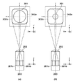
(撮像素子の瞳分割の概念)
次に、図2(b)に示した撮像素子107に含まれる画素の1つである画素210Gを例として、瞳分割の概念について図3を参照して説明する。図3(a)は射出瞳301が大きい場合、図3(b)は射出瞳301が小さい場合をそれぞれ示している。射出瞳301の大きさは、絞りの開口の大きさや、レンズを保持するレンズ枠などの大きさによって変化する。また、302aは副画素201aを射出瞳位置に投影した形状、302bは副画素201bを射出瞳位置に投影した形状を示している。
(Concept of pupil division of image sensor)
Next, the concept of pupil division will be described with reference to FIG. 3, taking as an example the pixel 210 </ b> G that is one of the pixels included in the
ここで、x方向に規則的に配列された副画素201aから取得した第1の像信号を、像信号ImgA(結像光学系の異なる射出瞳領域を通過した一対の光束から得た像信号の一方)とする。同様に、x方向に規則的に配列された副画素201bから取得した第2の像信号を像信号ImgB(結像光学系の異なる射出瞳領域を通過した一対の光束から得た像信号の他方)とする。焦点検出部121cは、像信号ImgAと像信号ImgBの相対的な像ずれ量から相関演算を用いてデフォーカス量を算出することで、結像光学系の焦点位置を算出することができる。このようにして求めた焦点位置に基づいて、結像光学系の焦点ずれ量を調節する。なお、ここではx方向に輝度分布を有する被写体に対応した構成について説明したが、同様の構成をy方向にも展開することでy方向に輝度分布を有する被写体にも対応した構成をとることが可能である。
Here, the first image signal acquired from the
(絞り値の大小による線像の違い)
図4は、副画素201a及び201bに対応する、撮影レンズの射出瞳位置における、絞りが開放状態の場合のx軸上の瞳強度分布の一例を示す図である。副画素201aの瞳強度分布401aに着目すると、+x側はセンサの瞳分割性能が十分でないことにより回折ボケのため緩やかなカーブになっている。対して、反対の−x側はレンズ枠によるケラレにより急なカーブになる。そのため、瞳強度分布401aは、強度のピークに対して非対称になっている。副画素201bの瞳強度分布401bに関しては、プラスマイナスが反転した形で瞳強度分布401aと同様のことが言える。
(Difference in line image depending on the aperture value)
FIG. 4 is a diagram illustrating an example of the pupil intensity distribution on the x-axis when the aperture is in the open state at the exit pupil position of the photographing lens corresponding to the sub-pixels 201a and 201b. Focusing on the
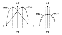
図5(a)は、絞り値が小さい図3(a)のような場合に、瞳強度分布をy方向に積分した線像、図5(b)は絞り値が大きい図3(b)のような場合に、瞳強度分布をy方向に積分した線像の一例をそれぞれ表している。図5(a)の線像501a、501bは、図4に示す瞳強度分布401a、401bと同様に、片側は回折ボケによる緩やかなカーブ、反対側は絞り枠のケラレによる急なカーブとなっている。一方、図5(b)の線像502a、502bは両側とも絞り枠のケラレによる急なカーブとなっている。なお、図5の破線は、各絞り値において、強度がピークとなる点を示している。図5から分かるように、絞りの大小により瞳強度分布は光軸に対しての非対称性の度合いが異なり、絞り値が小さいほど強度のピークに対する非対称性が大きくなる。
FIG. 5A is a line image obtained by integrating the pupil intensity distribution in the y direction in the case of FIG. 3A where the aperture value is small, and FIG. 5B is a diagram of FIG. 3B where the aperture value is large. In such a case, an example of a line image obtained by integrating the pupil intensity distribution in the y direction is shown. The
(エッジ抽出のためのフィルタ処理)
図6はフィルタ処理部121aで用いられるフィルタの特性を示す図であり、縦軸はフィルタの成分、横軸はフィルタの要素番号を表わしている。ここで、図6(a)に示すフィルタにおいて、フィルタの要素数を3、フィルタの要素番号をi、要素番号iのフィルタの成分をa[i]、n番目のフィルタ処理前の像信号をImg[n]、n番目のフィルタ処理後の像信号をImg’[n]と定義する。すると、以下に示す式(1)のような関係式になる。
(Filter processing for edge extraction)
FIG. 6 is a diagram showing the characteristics of the filter used in the

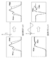
焦点検出精度を向上させるために使用するフィルタは図6に示すように主に2種類ある。一方は、図6(a)に示すように、フィルタの成分の値が全て正の成分で構成される第1のフィルタであるところの加算型フィルタである。この加算型フィルタの成分a[i]は、全て正の値である。加算型フィルタは高周波のノイズ除去や画素間の感度ばらつきを低減すること等の平滑化を目的としている。図7(a)に示すように、像信号701a、701bに図6(a)の加算型フィルタを適用すると、像信号702a、702bのようになる。 There are mainly two types of filters used to improve the focus detection accuracy as shown in FIG. On the other hand, as shown in FIG. 6A, an addition type filter is a first filter in which the values of the components of the filter are all composed of positive components. All the components a [i] of the addition filter are positive values. The addition filter is intended for smoothing such as high-frequency noise removal and reduction in sensitivity variation between pixels. As shown in FIG. 7A, when the addition filter of FIG. 6A is applied to the image signals 701a and 701b, the image signals 702a and 702b are obtained.
他方は、図6(b)に示す差分型フィルタであり、正と負の値で構成される。すなわち、上記式(1)に示す関係式において、この差分型フィルタの成分a[i]は、正と負の値をとる。差分型フィルタは像信号のDC成分のノイズ等を除去することで像のエッジを抽出し、相関演算時の2像の一致度を向上することを目的としている。図7(b)に示すように、像信号703a、703bに図6(b)のDC成分除去を目的とした差分型フィルタを適用すると、像信号704a、704bのようになる。焦点検出を行う際には第2のフィルタであるところの加算型フィルタと差分型フィルタの両方を通常適用する。 The other is a differential filter shown in FIG. 6B, which is composed of positive and negative values. That is, in the relational expression shown in the above formula (1), the component a [i] of the differential filter takes positive and negative values. The differential filter is intended to extract the edge of an image by removing noise or the like of the DC component of the image signal, and to improve the degree of coincidence of the two images during correlation calculation. As shown in FIG. 7B, when the differential filter for removing the DC component shown in FIG. 6B is applied to the image signals 703a and 703b, the image signals 704a and 704b are obtained. When performing focus detection, both the addition type filter and the difference type filter, which are the second filters, are usually applied.
差分型フィルタは、相関演算時の2像のDC成分のずれを補正し、像の一致度を向上させる。しかしながら、ケラレ等が発生し、2像の非対称性が大きな状態において差分型フィルタを適用すると、図8(a)に示したように、ケラレa、ケラレbの影響で傾きが異なる部分が強調されてしまう(ケラレafilter、ケラレbfilter)。図8(b)は2本チャートの場合の像信号であるが、差分型フィルタを適用したことにより、ケラレa、ケラレbが強調され、2像の一致度が逆に下がっていることがわかる(ケラレafilter、ケラレbfilter)。よって、ケラレが発生する等の影響により2像の非対称性が大きな場合においては、差分型フィルタ処理を行わず、第1のフィルタであるところの加算型のフィルタ処理のみを行った方が2像の一致度は良い。 The differential filter corrects the deviation between the DC components of the two images during the correlation calculation, and improves the degree of coincidence of the images. However, when vignetting or the like occurs and the differential filter is applied in a state in which the asymmetry of the two images is large, as shown in FIG. (Vignetting a filter , vignetting b filter ). FIG. 8B shows an image signal in the case of two charts, but it can be seen that by applying the differential filter, vignetting a and vignetting b are enhanced, and the degree of coincidence of the two images is decreased. (Vignetting a filter , Vignetting b filter ). Therefore, when the asymmetry of the two images is large due to the influence of vignetting or the like, the difference filter processing is not performed and only the addition filter processing as the first filter is performed. The degree of agreement is good.
絞り値が小さい場合、図5(a)を参照して説明したように、2像の非対称性が大きい。その反面、基線長は長くとれるため、敏感度は小さく、DC成分のノイズの影響は小さい。よって、絞り値が小さい場合、第1のフィルタであるところの加算型フィルタ処理を適用した方が良い。逆に、絞り値が大きい場合、図5(b)を参照して説明したように、絞り値が小さい場合に比べて2像の非対称性は小さい。その反面、基線長が短く、敏感度が大きいためDC成分のノイズの影響が大きくなる。よって、値が正と負の成分で構成される第2のフィルタであるところの加算型フィルタ処理と差分型フィルタ処理の両方を適用した方が2像の一致度は良い。 When the aperture value is small, the asymmetry of the two images is large as described with reference to FIG. On the other hand, since the base line length can be long, the sensitivity is small and the influence of the noise of the DC component is small. Therefore, when the aperture value is small, it is better to apply the addition type filter processing which is the first filter. On the contrary, when the aperture value is large, as described with reference to FIG. 5B, the asymmetry of the two images is smaller than when the aperture value is small. On the other hand, since the base line length is short and the sensitivity is high, the influence of DC component noise becomes large. Therefore, the degree of coincidence between the two images is better when both the addition type filter processing and the difference type filter processing, which are the second filters whose values are composed of positive and negative components, are applied.
このように、2像の非対称性は絞り枠の大きさに依存することが大きいため、本実施形態においては、絞り値が所定閾値より小さい場合は、加算型フィルタ処理を行い、絞り値が所定閾値以上の場合は加算型フィルタ処理と差分型フィルタ処理とを行う。以上のように2種類のフィルタを適切に選択することで、デフォーカスの方向検出精度を向上させることができる。 As described above, since the asymmetry of the two images largely depends on the size of the aperture frame, in this embodiment, when the aperture value is smaller than the predetermined threshold value, addition type filter processing is performed, and the aperture value is predetermined. If the value is greater than or equal to the threshold value, addition type filter processing and difference type filter processing are performed. As described above, defocus direction detection accuracy can be improved by appropriately selecting two types of filters.
図9は、本実施形態における焦点検出処理を示すフローチャートである。まず、焦点検出が開始されると、S11で結像光学系を介して入射する被写体光を撮像素子107が光電変換して、像信号を生成し、フィルタ処理部121aに出力する。次に、S12で絞り情報出力部121bにより得られる絞り値の判定を行う。その結果、絞り値が所定閾値(例えばF11)より小さい場合はS13に進み、フィルタ処理部121aは像信号を第1のフィルタで処理を行う。一方、絞り値が所定閾値以上の場合はS14に進んでフィルタ処理部121aにより第2のフィルタにより像信号の処理を行う。フィルタ処理後はS15で焦点検出部121cにて、フィルタ処理部121aによりフィルタ処理をされた像信号を用いて、公知の技術である相関演算を行い、結像光学系の焦点検出を行う。フォーカスアクチュエータ114は焦点検出部121cの出力に基づいて第3レンズ群105を駆動する。以上説明した像信号取得から相関演算までを1回以上行い、最終的にS16で焦点検出終了と判定されれば、焦点検出を終了する。
FIG. 9 is a flowchart showing focus detection processing in the present embodiment. First, when focus detection is started, the
本発明が特許文献2における2種類の差分型フィルタをケラレに応じて選択する方法より優れている点は、絞り値が小さいときにはフィルタ処理部121aは、加算型フィルタのみを用いてフィルタ処理を行っている所にある。差分型のフィルタを使わないことにより、波形の非対称性に起因する歪みを強調することなく精度の高いデフォーカスの方向検出性能が得られる。
The present invention is superior to the method of selecting two types of differential filters according to vignetting in Patent Document 2 when the aperture value is small, the
以上のように本実施形態によれば、瞳分割位相差方式の焦点検出において、瞳分割性能が十分でないため、ケラレの影響が大きい場合においても、デフォーカスの方向検出性能を向上させることができる。 As described above, according to the present embodiment, the pupil division performance is not sufficient in the focus detection of the pupil division phase difference method, and therefore the defocus direction detection performance can be improved even when the influence of vignetting is large. .
<変形例>
上述した実施形態と別のフィルタ選択方法として、瞳距離と絞り値が分かれば、撮影レンズによるケラレの度合い(例えば、ケラレが無い瞳領域に対する、ケラレた瞳領域の割合)を評価することができる。よって、瞳距離と絞り値をフィルタ処理部121aに送り、フィルタ処理部121aにてケラレの度合いを評価し、その結果に応じて、第1または第2のフィルタの選択を行ってもよい。
<Modification>
As a filter selection method different from the embodiment described above, if the pupil distance and the aperture value are known, the degree of vignetting by the taking lens (for example, the ratio of the vignetting pupil area to the vignetting-free pupil area) can be evaluated. . Therefore, the pupil distance and the aperture value may be sent to the
図10は、変形例における焦点検出処理を示すフローチャートである。まず、焦点検出が開始されると、S11で結像光学系を介して入射する被写体光を撮像素子107が光電変換して、像信号を生成し、フィルタ処理部121aに出力する。次に、S22で絞り情報出力部121bにより絞り値を、また、レンズROM110から、瞳距離を含む瞳情報を取得する。そして、S23において、取得した絞り値及び瞳距離からケラレの度合いを評価し、S24において評価したケラレの度合いの判定を行う。その結果、ケラレの度合いが所定閾値より大きい場合はS13に進み、フィルタ処理部121aは像信号を第1のフィルタで処理を行う。一方、ケラレの度合いが所定閾値以下の場合はS14に進んでフィルタ処理部121aにより第2のフィルタにより像信号の処理を行う。これ以降の処理は、図9を参照して上述した処理と同様であるため、説明を省略する。
FIG. 10 is a flowchart showing focus detection processing in the modification. First, when focus detection is started, the
このように変形例によれば、絞り値に加えて更に瞳距離を用いてケラレの度合いを評価し、その結果に応じて第1または第2のフィルタを選択する。これにより、瞳分割位相差方式の焦点検出において、瞳分割性能が十分でないため、ケラレの影響が大きい場合においても、デフォーカスの方向検出性能を向上させることができる。 As described above, according to the modification, the degree of vignetting is evaluated using the pupil distance in addition to the aperture value, and the first or second filter is selected according to the result. Thereby, in the focus detection of the pupil division phase difference method, since the pupil division performance is not sufficient, the defocus direction detection performance can be improved even when the influence of vignetting is large.
Claims (5)
加算型フィルタで構成された第1のフィルタと、
加算型フィルタと差分型フィルタとから構成された第2のフィルタと、
前記結像光学系の絞り値を取得する取得手段と、
前記絞り値が予め決められた閾値より小さい場合には前記第1のフィルタを選択し、前記絞り値が前記閾値以上の場合には前記第2のフィルタを選択して、該選択したフィルタを用いて前記第1の像信号及び第2の像信号それぞれをフィルタ処理するフィルタ処理手段と、
前記フィルタ処理手段により前記フィルタ処理された前記第1の像信号及び第2の像信号に基づいて、位相差方式の焦点検出を行う焦点検出手段と
を有することを特徴とする撮像装置。 A pair of photoelectric elements capable of outputting a first image signal and a second image signal, which are a pair of image signals obtained by independently receiving a pair of light beams that have passed through different exit pupil regions of the imaging optical system, respectively. An imaging device having a plurality of pixels arranged two-dimensionally, including a pixel having a conversion unit;
A first filter composed of a summing filter;
A second filter composed of an addition filter and a difference filter;
Obtaining means for obtaining an aperture value of the imaging optical system;
When the aperture value is smaller than a predetermined threshold, the first filter is selected, and when the aperture value is greater than or equal to the threshold, the second filter is selected and the selected filter is used. and filtering means for filtering each of the first image signal and second image signal Te,
An imaging apparatus comprising: focus detection means for performing phase difference type focus detection based on the first image signal and the second image signal filtered by the filter processing means.
加算型フィルタで構成された第1のフィルタと、
加算型フィルタと差分型フィルタとから構成された第2のフィルタと、
前記結像光学系の絞り値及び、前記結像光学系の瞳距離を取得する取得手段と、
前記絞り値と前記瞳距離とに基づいてケラレの度合いを評価し、該ケラレの度合いが予め決められた閾値より大きい場合には前記第1のフィルタを選択し、前記ケラレの度合いが前記閾値以下の場合には前記第2のフィルタを選択して、該選択したフィルタを用いて前記第1の像信号及び第2の像信号それぞれをフィルタ処理するフィルタ処理手段と、
前記フィルタ処理手段により前記フィルタ処理された前記第1の像信号及び第2の像信号に基づいて、位相差方式の焦点検出を行う焦点検出手段と
を有することを特徴とする撮像装置。 A pair of photoelectric elements capable of outputting a first image signal and a second image signal, which are a pair of image signals obtained by independently receiving a pair of light beams that have passed through different exit pupil regions of the imaging optical system, respectively. An imaging device having a plurality of pixels arranged two-dimensionally, including a pixel having a conversion unit;
A first filter composed of a summing filter;
A second filter composed of an addition filter and a difference filter;
Acquisition means for acquiring the aperture value of the imaging optical system and the pupil distance of the imaging optical system;
The degree of vignetting is evaluated based on the aperture value and the pupil distance. When the degree of vignetting is larger than a predetermined threshold, the first filter is selected, and the degree of vignetting is less than or equal to the threshold. and filtering means for selecting said second filter, for filtering each of the first image signal and second image signal by using the selected filter in the case of,
An imaging apparatus comprising: focus detection means for performing phase difference type focus detection based on the first image signal and the second image signal filtered by the filter processing means.
取得手段が、前記結像光学系の絞り値を取得する取得工程と、
フィルタ処理手段が、前記絞り値が予め決められた閾値より小さい場合には加算型フィルタで構成された第1のフィルタにより前記第1の像信号及び第2の像信号をフィルタ処理し、前記絞り値が前記閾値以上の場合には加算型フィルタと差分型フィルタとから構成された第2のフィルタにより前記第1の像信号及び第2の像信号それぞれをフィルタ処理するフィルタ処理工程と、
焦点検出手段が、前記フィルタ処理工程で前記フィルタ処理された前記第1の像信号及び第2の像信号に基づいて、位相差方式の焦点検出を行う焦点検出工程と
を有することを特徴とする焦点検出方法。 A pair of photoelectric elements capable of outputting a first image signal and a second image signal, which are a pair of image signals obtained by independently receiving a pair of light beams that have passed through different exit pupil regions of the imaging optical system, respectively. A focus detection method for performing focus detection based on the first image signal and the second image signal obtained from an image sensor having a plurality of pixels arranged two-dimensionally including a pixel having a conversion unit. And
An acquisition step of acquiring an aperture value of the imaging optical system;
When the aperture value is smaller than a predetermined threshold, the filter processing means filters the first image signal and the second image signal with a first filter constituted by an addition filter, and A filter processing step of filtering each of the first image signal and the second image signal by a second filter composed of an addition filter and a difference filter when the value is equal to or greater than the threshold;
The focus detection means includes a focus detection step of performing phase difference type focus detection based on the first image signal and the second image signal filtered in the filter processing step. Focus detection method.
取得手段が、前記結像光学系の絞り値及び瞳距離を取得する取得工程と、
評価手段が、前記絞り値と前記瞳距離とに基づいてケラレの度合いを評価する評価工程と、
フィルタ処理手段が、前記ケラレの度合いが予め決められた閾値より大きい場合には加算型フィルタで構成された第1のフィルタにより前記一対の像信号をフィルタ処理し、前記ケラレの度合いが前記閾値以下の場合には加算型フィルタと差分型フィルタとから構成された第2のフィルタにより前記第1の像信号及び第2の像信号それぞれをフィルタ処理するフィルタ処理工程と、
焦点検出手段が、前記フィルタ処理手段により前記フィルタ処理された前記第1の像信号及び第2の像信号に基づいて、位相差方式の焦点検出を行う焦点検出工程と
を有することを特徴とする焦点検出方法。 Two-dimensionally arranged including a pixel having a pair of photoelectric conversion units capable of outputting a pair of image signals obtained by independently receiving a pair of light beams that have passed through different exit pupil regions of the imaging optical system. A focus detection method for performing focus detection based on a first image signal and a second image signal that are the pair of image signals obtained from an imaging device having a plurality of pixels,
An acquisition step in which the acquisition means acquires the aperture value and pupil distance of the imaging optical system;
An evaluation unit evaluates the degree of vignetting based on the aperture value and the pupil distance;
When the degree of vignetting is greater than a predetermined threshold, the filter processing unit filters the pair of image signals with a first filter configured by an addition filter, and the degree of vignetting is less than or equal to the threshold. In this case, a filter processing step of filtering each of the first image signal and the second image signal by a second filter composed of an addition filter and a difference filter;
A focus detection unit comprising: a focus detection step of performing phase difference type focus detection based on the first image signal and the second image signal filtered by the filter processing unit; Focus detection method.
Priority Applications (4)
| Application Number | Priority Date | Filing Date | Title |
|---|---|---|---|
| JP2011272746A JP5898481B2 (en) | 2011-12-13 | 2011-12-13 | Imaging apparatus and focus detection method |
| EP12194091.0A EP2605511B1 (en) | 2011-12-13 | 2012-11-23 | Image capturing apparatus and focus detection method |
| US13/692,173 US8854529B2 (en) | 2011-12-13 | 2012-12-03 | Image capturing apparatus and focus detection method |
| CN201210539085.1A CN103167236B (en) | 2011-12-13 | 2012-12-13 | Picture pick-up device, imageing sensor and focus detecting method |
Applications Claiming Priority (1)
| Application Number | Priority Date | Filing Date | Title |
|---|---|---|---|
| JP2011272746A JP5898481B2 (en) | 2011-12-13 | 2011-12-13 | Imaging apparatus and focus detection method |
Publications (3)
| Publication Number | Publication Date |
|---|---|
| JP2013125095A JP2013125095A (en) | 2013-06-24 |
| JP2013125095A5 JP2013125095A5 (en) | 2015-02-05 |
| JP5898481B2 true JP5898481B2 (en) | 2016-04-06 |
Family
ID=47471499
Family Applications (1)
| Application Number | Title | Priority Date | Filing Date |
|---|---|---|---|
| JP2011272746A Active JP5898481B2 (en) | 2011-12-13 | 2011-12-13 | Imaging apparatus and focus detection method |
Country Status (4)
| Country | Link |
|---|---|
| US (1) | US8854529B2 (en) |
| EP (1) | EP2605511B1 (en) |
| JP (1) | JP5898481B2 (en) |
| CN (1) | CN103167236B (en) |
Families Citing this family (15)
| Publication number | Priority date | Publication date | Assignee | Title |
|---|---|---|---|---|
| JP6014452B2 (en) | 2012-10-16 | 2016-10-25 | キヤノン株式会社 | FOCUS DETECTION DEVICE, LENS DEVICE HAVING THE SAME, AND IMAGING DEVICE |
| JP5911445B2 (en) * | 2013-03-19 | 2016-04-27 | キヤノン株式会社 | Imaging apparatus and control method thereof |
| JP6334847B2 (en) * | 2013-04-17 | 2018-05-30 | キヤノン株式会社 | FOCUS DETECTION DEVICE, FOCUS DETECTION METHOD AND PROGRAM, AND IMAGING DEVICE |
| WO2015015718A1 (en) * | 2013-07-31 | 2015-02-05 | パナソニック インテレクチュアル プロパティ コーポレーション オブ アメリカ | Sensor assembly |
| JP6312487B2 (en) | 2014-03-26 | 2018-04-18 | キヤノン株式会社 | Image processing apparatus, control method therefor, and program |
| JP6335589B2 (en) | 2014-03-31 | 2018-05-30 | キヤノン株式会社 | Distance detection device, imaging device, distance detection method, and parallax amount detection device |
| JP6587380B2 (en) | 2014-09-12 | 2019-10-09 | キヤノン株式会社 | Image processing apparatus, imaging apparatus, image processing method, program, and storage medium |
| JP2016070994A (en) * | 2014-09-26 | 2016-05-09 | キヤノン株式会社 | Imaging device and control method of the same, program and recording medium |
| JP6171110B2 (en) * | 2014-11-18 | 2017-07-26 | 富士フイルム株式会社 | Focus control device, focus control method, focus control program, lens device, imaging device |
| KR102363433B1 (en) | 2015-01-15 | 2022-02-16 | 삼성전자주식회사 | Image sensors |
| JP6506560B2 (en) * | 2015-01-20 | 2019-04-24 | キヤノン株式会社 | Focus control device and method therefor, program, storage medium |
| KR102481481B1 (en) | 2015-12-15 | 2022-12-26 | 삼성전자 주식회사 | Image sensor and method of manufacturing the same |
| JP6727814B2 (en) * | 2016-01-14 | 2020-07-22 | キヤノン株式会社 | IMAGING DEVICE, IMAGING DEVICE CONTROL METHOD, AND PROGRAM |
| US10523860B2 (en) | 2016-05-12 | 2019-12-31 | Canon Kabushiki Kaisha | Focus detection device, control method thereof, and image capture apparatus |
| JP7199845B2 (en) * | 2018-06-19 | 2023-01-06 | キヤノン株式会社 | Image processing device, image processing method and program |
Family Cites Families (25)
| Publication number | Priority date | Publication date | Assignee | Title |
|---|---|---|---|---|
| US4731864A (en) * | 1986-02-21 | 1988-03-15 | Rca Corporation | Photographic camera simulation systems working from computer memory |
| US4975726A (en) * | 1987-11-25 | 1990-12-04 | Matsushita Electric Industrial Co., Ltd. | Automatic focusing apparatus |
| JPH01216306A (en) | 1988-02-24 | 1989-08-30 | Canon Inc | Focus detecting device having image pickup means |
| US5083150A (en) * | 1989-03-03 | 1992-01-21 | Olympus Optical Co., Ltd. | Automatic focusing apparatus |
| US5193124A (en) * | 1989-06-29 | 1993-03-09 | The Research Foundation Of State University Of New York | Computational methods and electronic camera apparatus for determining distance of objects, rapid autofocusing, and obtaining improved focus images |
| JP3103587B2 (en) * | 1990-04-25 | 2000-10-30 | オリンパス光学工業株式会社 | Automatic focusing device |
| JP3240648B2 (en) * | 1991-11-01 | 2001-12-17 | キヤノン株式会社 | Focus detection device |
| US5367153A (en) * | 1991-11-01 | 1994-11-22 | Canon Kabushiki Kaisha | Apparatus for detecting the focus adjusting state of an objective lens by performing filter processing |
| JP2715958B2 (en) * | 1995-03-03 | 1998-02-18 | 株式会社ニコン | Focus detection device |
| US5874994A (en) * | 1995-06-30 | 1999-02-23 | Eastman Kodak Company | Filter employing arithmetic operations for an electronic sychronized digital camera |
| US7358999B2 (en) * | 1998-03-10 | 2008-04-15 | Canon Kabushiki Kaisha | Focus sensing apparatus, focus sensing method using phase-differential detection and computer-readable storage medium therefor |
| JP2000207549A (en) * | 1999-01-11 | 2000-07-28 | Olympus Optical Co Ltd | Image processor |
| JP4217415B2 (en) * | 2001-04-04 | 2009-02-04 | オリンパス株式会社 | Electronic imaging device |
| JP4565784B2 (en) * | 2001-09-20 | 2010-10-20 | Hoya株式会社 | Digital camera |
| US7099555B2 (en) * | 2003-08-20 | 2006-08-29 | Canon Kabushiki Kaisha | Light amount adjusting apparatus, optical equipment, optical filter and image-taking apparatus |
| FR2881011B1 (en) * | 2005-01-19 | 2007-06-29 | Dxo Labs Sa | METHOD FOR PRODUCING AN IMAGE CAPTURE AND / OR RETRIEVAL APPARATUS AND APPARATUS OBTAINED THEREBY |
| CA2834883C (en) * | 2005-03-07 | 2018-01-23 | Dxo Labs | Method of controlling an action, such as a sharpness modification, using a colour digital image |
| JP5157084B2 (en) * | 2006-05-17 | 2013-03-06 | 株式会社ニコン | Correlation calculation device, focus detection device, and imaging device |
| US7729602B2 (en) * | 2007-03-09 | 2010-06-01 | Eastman Kodak Company | Camera using multiple lenses and image sensors operable in a default imaging mode |
| US7859588B2 (en) * | 2007-03-09 | 2010-12-28 | Eastman Kodak Company | Method and apparatus for operating a dual lens camera to augment an image |
| US8223256B2 (en) * | 2008-04-11 | 2012-07-17 | Nikon Corporation | Correlation calculation method, correlation calculation device, focus detection device and image-capturing apparatus |
| EP2490060B1 (en) * | 2009-10-13 | 2018-06-13 | Canon Kabushiki Kaisha | Focusing device and focusing method |
| US8411982B2 (en) * | 2010-02-16 | 2013-04-02 | Dialogic Corporation | Universal blurriness measurement approach for digital imagery |
| US8494301B2 (en) * | 2010-09-16 | 2013-07-23 | Eastman Kodak Company | Refocusing images using scene captured images |
| US10032254B2 (en) * | 2010-09-28 | 2018-07-24 | MAX-PLANCK-Gesellschaft zur Förderung der Wissenschaften e.V. | Method and device for recovering a digital image from a sequence of observed digital images |
-
2011
- 2011-12-13 JP JP2011272746A patent/JP5898481B2/en active Active
-
2012
- 2012-11-23 EP EP12194091.0A patent/EP2605511B1/en active Active
- 2012-12-03 US US13/692,173 patent/US8854529B2/en active Active
- 2012-12-13 CN CN201210539085.1A patent/CN103167236B/en active Active
Also Published As
| Publication number | Publication date |
|---|---|
| EP2605511B1 (en) | 2017-04-05 |
| CN103167236B (en) | 2016-09-28 |
| JP2013125095A (en) | 2013-06-24 |
| US8854529B2 (en) | 2014-10-07 |
| EP2605511A3 (en) | 2013-11-06 |
| US20130147998A1 (en) | 2013-06-13 |
| EP2605511A2 (en) | 2013-06-19 |
| CN103167236A (en) | 2013-06-19 |
Similar Documents
| Publication | Publication Date | Title |
|---|---|---|
| JP5898481B2 (en) | Imaging apparatus and focus detection method | |
| JP5645846B2 (en) | Focus adjustment device and focus adjustment method | |
| JP5676962B2 (en) | Focus detection apparatus and imaging apparatus | |
| US9204033B2 (en) | Image capture apparatus | |
| JP6249825B2 (en) | Imaging device, control method thereof, and control program | |
| JP5947601B2 (en) | FOCUS DETECTION DEVICE, ITS CONTROL METHOD, AND IMAGING DEVICE | |
| JP6239857B2 (en) | Imaging apparatus and control method thereof | |
| JP6239855B2 (en) | Focus adjustment apparatus, focus adjustment method and program, and imaging apparatus | |
| US9160918B2 (en) | Focus control apparatus and method for performing focus control by phase difference detection, and image capturing apparatus | |
| US20180041744A1 (en) | Image processing apparatus, image pickup apparatus, image processing method, and non-transitory computer-readable storage medium | |
| WO2018150925A1 (en) | Focus detection device, focus detection method, and focus detection program | |
| JP6862102B2 (en) | Control device, image pickup device, control method, program, and storage medium | |
| JP2012220790A (en) | Imaging apparatus | |
| JP2014130231A (en) | Imaging apparatus, method for controlling the same, and control program | |
| JP5735784B2 (en) | Imaging device and control method thereof, lens device and control method thereof | |
| JP2016057402A (en) | Imaging device and method for controlling the same | |
| JP2014238517A (en) | Imaging device, imaging system, imaging device control method, program, and storage medium | |
| JP2015022028A (en) | Imaging device | |
| JP6442824B2 (en) | Focus detection device | |
| JP2018110299A (en) | Image processing method, image processing device, and imaging device | |
| JP2024040227A (en) | Focus detector and image pick-up device | |
| JP2019219499A (en) | Controller, imaging apparatus, control method, program, and storage medium | |
| JP2019061264A (en) | Focus detector, camera, and electronic apparatus | |
| JP2019071591A (en) | Imaging apparatus and method for controlling the same | |
| JP2017169012A (en) | Image processing device, control method of image processing device, and imaging apparatus |
Legal Events
| Date | Code | Title | Description |
|---|---|---|---|
| A521 | Request for written amendment filed |
Free format text: JAPANESE INTERMEDIATE CODE: A523 Effective date: 20141212 |
|
| A621 | Written request for application examination |
Free format text: JAPANESE INTERMEDIATE CODE: A621 Effective date: 20141212 |
|
| A977 | Report on retrieval |
Free format text: JAPANESE INTERMEDIATE CODE: A971007 Effective date: 20150813 |
|
| A131 | Notification of reasons for refusal |
Free format text: JAPANESE INTERMEDIATE CODE: A131 Effective date: 20150821 |
|
| A521 | Request for written amendment filed |
Free format text: JAPANESE INTERMEDIATE CODE: A523 Effective date: 20151019 |
|
| TRDD | Decision of grant or rejection written | ||
| A01 | Written decision to grant a patent or to grant a registration (utility model) |
Free format text: JAPANESE INTERMEDIATE CODE: A01 Effective date: 20160205 |
|
| A61 | First payment of annual fees (during grant procedure) |
Free format text: JAPANESE INTERMEDIATE CODE: A61 Effective date: 20160304 |
|
| R151 | Written notification of patent or utility model registration |
Ref document number: 5898481 Country of ref document: JP Free format text: JAPANESE INTERMEDIATE CODE: R151 |