JP6000520B2 - Imaging apparatus and control method and program thereof - Google Patents
Imaging apparatus and control method and program thereof Download PDFInfo
- Publication number
- JP6000520B2 JP6000520B2 JP2011162093A JP2011162093A JP6000520B2 JP 6000520 B2 JP6000520 B2 JP 6000520B2 JP 2011162093 A JP2011162093 A JP 2011162093A JP 2011162093 A JP2011162093 A JP 2011162093A JP 6000520 B2 JP6000520 B2 JP 6000520B2
- Authority
- JP
- Japan
- Prior art keywords
- focus
- image
- evaluation
- correlation
- contrast
- Prior art date
- Legal status (The legal status is an assumption and is not a legal conclusion. Google has not performed a legal analysis and makes no representation as to the accuracy of the status listed.)
- Expired - Fee Related
Links
Images


Classifications
-
- G—PHYSICS
- G02—OPTICS
- G02B—OPTICAL ELEMENTS, SYSTEMS OR APPARATUS
- G02B7/00—Mountings, adjusting means, or light-tight connections, for optical elements
- G02B7/28—Systems for automatic generation of focusing signals
-
- G—PHYSICS
- G02—OPTICS
- G02B—OPTICAL ELEMENTS, SYSTEMS OR APPARATUS
- G02B7/00—Mountings, adjusting means, or light-tight connections, for optical elements
- G02B7/28—Systems for automatic generation of focusing signals
- G02B7/34—Systems for automatic generation of focusing signals using different areas in a pupil plane
-
- G—PHYSICS
- G02—OPTICS
- G02B—OPTICAL ELEMENTS, SYSTEMS OR APPARATUS
- G02B7/00—Mountings, adjusting means, or light-tight connections, for optical elements
- G02B7/28—Systems for automatic generation of focusing signals
- G02B7/285—Systems for automatic generation of focusing signals including two or more different focus detection devices, e.g. both an active and a passive focus detecting device
-
- G—PHYSICS
- G02—OPTICS
- G02B—OPTICAL ELEMENTS, SYSTEMS OR APPARATUS
- G02B7/00—Mountings, adjusting means, or light-tight connections, for optical elements
- G02B7/28—Systems for automatic generation of focusing signals
- G02B7/36—Systems for automatic generation of focusing signals using image sharpness techniques, e.g. image processing techniques for generating autofocus signals
-
- G—PHYSICS
- G03—PHOTOGRAPHY; CINEMATOGRAPHY; ANALOGOUS TECHNIQUES USING WAVES OTHER THAN OPTICAL WAVES; ELECTROGRAPHY; HOLOGRAPHY
- G03B—APPARATUS OR ARRANGEMENTS FOR TAKING PHOTOGRAPHS OR FOR PROJECTING OR VIEWING THEM; APPARATUS OR ARRANGEMENTS EMPLOYING ANALOGOUS TECHNIQUES USING WAVES OTHER THAN OPTICAL WAVES; ACCESSORIES THEREFOR
- G03B13/00—Viewfinders; Focusing aids for cameras; Means for focusing for cameras; Autofocus systems for cameras
- G03B13/32—Means for focusing
- G03B13/34—Power focusing
- G03B13/36—Autofocus systems
-
- H—ELECTRICITY
- H04—ELECTRIC COMMUNICATION TECHNIQUE
- H04N—PICTORIAL COMMUNICATION, e.g. TELEVISION
- H04N23/00—Cameras or camera modules comprising electronic image sensors; Control thereof
- H04N23/60—Control of cameras or camera modules
-
- H—ELECTRICITY
- H04—ELECTRIC COMMUNICATION TECHNIQUE
- H04N—PICTORIAL COMMUNICATION, e.g. TELEVISION
- H04N23/00—Cameras or camera modules comprising electronic image sensors; Control thereof
- H04N23/60—Control of cameras or camera modules
- H04N23/67—Focus control based on electronic image sensor signals
- H04N23/672—Focus control based on electronic image sensor signals based on the phase difference signals
-
- H—ELECTRICITY
- H04—ELECTRIC COMMUNICATION TECHNIQUE
- H04N—PICTORIAL COMMUNICATION, e.g. TELEVISION
- H04N23/00—Cameras or camera modules comprising electronic image sensors; Control thereof
- H04N23/60—Control of cameras or camera modules
- H04N23/67—Focus control based on electronic image sensor signals
- H04N23/673—Focus control based on electronic image sensor signals based on contrast or high frequency components of image signals, e.g. hill climbing method
-
- H—ELECTRICITY
- H04—ELECTRIC COMMUNICATION TECHNIQUE
- H04N—PICTORIAL COMMUNICATION, e.g. TELEVISION
- H04N25/00—Circuitry of solid-state image sensors [SSIS]; Control thereof
- H04N25/70—SSIS architectures; Circuits associated therewith
- H04N25/703—SSIS architectures incorporating pixels for producing signals other than image signals
- H04N25/704—Pixels specially adapted for focusing, e.g. phase difference pixel sets
Landscapes
- Physics & Mathematics (AREA)
- General Physics & Mathematics (AREA)
- Engineering & Computer Science (AREA)
- Optics & Photonics (AREA)
- Multimedia (AREA)
- Signal Processing (AREA)
- Computer Vision & Pattern Recognition (AREA)
- Studio Devices (AREA)
- Automatic Focus Adjustment (AREA)
- Focusing (AREA)
Description
本発明は、被写体像を光電変換する撮像素子を有する撮像装置およびその制御方法に関し、特に撮像素子から出力される光電変換信号に基づくオートフォーカス(以下AF)制御装置および方法に関する。 The present invention relates to an imaging apparatus having an imaging element that photoelectrically converts a subject image and a control method thereof, and more particularly to an autofocus (hereinafter referred to as AF) control apparatus and method based on a photoelectric conversion signal output from the imaging element.
従来、デジタルカメラなどでのピント調整のためのオートフォーカス制御として、例えば主にデジタル一眼レフカメラで使用される位相差AF制御とコンパクトカメラなどに使用されるコントラストAF制御がある。これらのAF制御の特徴は、例えば位相差AFでは高速なピント調整が可能であること、またコントラストAFでは厳密なピント合わせが可能であることである。 Conventionally, as autofocus control for focus adjustment in a digital camera or the like, for example, there are phase difference AF control mainly used in a digital single-lens reflex camera and contrast AF control used in a compact camera or the like. A feature of these AF controls is, for example, that high-speed focus adjustment is possible with phase difference AF, and strict focus adjustment is possible with contrast AF.
例えば、特許文献1には、位相差AFセンサの信号に基づいてコントラスト評価を行う方法が開示されている。また、特許文献2には、異なる瞳領域を通過した光束を個別に受光可能な撮像素子を使用し、撮像素子から出力された撮像信号を用いて(即ち撮像後に)ピント調整を行った画像を生成する手法が開示されている。
For example,
しかしながら、上述の特許文献に開示された従来技術では、十分なピント精度が得られず、狙った被写体にピントが合わない像しか得られない場合がある。すなわち特許文献1では、コントラスト計算を行うセンサと撮像を行うセンサが異なっているので必ずしもピント精度を向上できない場合がある。特許文献2では、撮影後にピント位置を変化させた像を得ることができるが、ピントを正確に変化させることができる範囲には限界があり、それを超えた場合には正常に像を得ることが困難となる。
そこで、本発明の目的は、撮像素子に入射する異なる瞳領域を通過した光束の情報に基づいて位相差AFとコントラストAFを同時に実現することで、高速かつ合焦精度の高いAFを行う撮影を可能にした撮像装置を提供することである。
However, with the conventional techniques disclosed in the above-described patent documents, sufficient focus accuracy may not be obtained, and only an image that is not in focus on the target subject may be obtained. That is, in
Accordingly, an object of the present invention is to realize high-speed and high-precision AF shooting by simultaneously realizing phase-difference AF and contrast AF based on information on light beams that have passed through different pupil regions incident on the image sensor. It is an object of the present invention to provide an imaging device that has been made possible.
上記本発明の目的を達成するため、本発明の撮像装置は、複数のマイクロレンズと、前記複数のマイクロレンズのそれぞれに複数の光電変換部が対応して画像信号を出力する撮像素子とを含む撮像装置において、前記各マイクロレンズに対応する複数の前記光電変換部からの画像信号をシフトして、ピント位置の異なる画像を生成する像生成手段と、前記像生成手段により生成された前記画像のコントラストの評価値を計算し、前記コントラストの評価値に基づいてコントラストピント位置を決定するコントラスト評価手段と、前記各マイクロレンズに対応する複数の光電変換部から得られる画像信号間の相関の評価値を計算し、前記相関の評価値に基づいて相関ピント位置を決定する相関計算手段と、前記相関ピント位置が、前記像生成手段が生成する画像のピント位置より合焦位置から遠いとき、前記コントラスト評価手段による決定を省略して前記相関計算手段により決定された前記相関ピント位置に基づいて被写体のピント評価位置を決定し、前記相関ピント位置が、前記像生成手段が生成する画像のピント位置より合焦位置に近いとき、前記コントラスト評価手段により決定された前記コントラストピント位置に基づいて前記被写体のピント評価値を決定するピント評価手段と、を備える。
In order to achieve the above object of the present invention, an imaging apparatus of the present invention includes a plurality of microlenses and an image sensor that outputs an image signal corresponding to each of the plurality of microlenses by a plurality of photoelectric conversion units. In the imaging apparatus, an image generation unit that shifts image signals from the plurality of photoelectric conversion units corresponding to the microlenses to generate images having different focus positions, and an image generation unit that generates the image generated by the image generation unit A contrast evaluation value for calculating a contrast evaluation value and determining a contrast focus position based on the contrast evaluation value, and an evaluation value for a correlation between image signals obtained from a plurality of photoelectric conversion units corresponding to the microlenses. was calculated, and the correlation calculating means for determining a correlation focus position based on the evaluation value of the correlation, the correlation focus position, the image generation hands Determining the focus evaluation position of the subject based on the correlation focus position determined by the correlation calculation means by omitting the determination by the contrast evaluation means when the image is far from the focus position than the focus position of the generated image, Focus evaluation for determining the focus evaluation value of the subject based on the contrast focus position determined by the contrast evaluation means when the correlation focus position is closer to the focus position than the focus position of the image generated by the image generation means Means .
本発明によれば、高速かつ合焦精度の高いAF制御を可能にした撮影を行える撮像装置を提供することができる。 According to the present invention, it is possible to provide an imaging apparatus capable of performing imaging that enables AF control with high speed and high focusing accuracy.
以下に、本発明の好ましい実施の形態を、添付の図面に基づいて詳細に説明する。 Hereinafter, preferred embodiments of the present invention will be described in detail with reference to the accompanying drawings.
以下、図1から図7を参照して、本発明の第1の実施例に係わる撮影装置を説明する。 The photographing apparatus according to the first embodiment of the present invention will be described below with reference to FIGS.
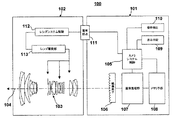
図1は本発明に係わる撮影装置としてのデジタルカメラのシステム構成を示すブロック図である。本カメラシステムは、撮影モードとして静止画撮影モードと動画撮影モードを有し、本件発明が目的とするAF制御を各撮影モードおいて達成する構成を有する。 FIG. 1 is a block diagram showing a system configuration of a digital camera as a photographing apparatus according to the present invention. This camera system has a still image shooting mode and a moving image shooting mode as shooting modes, and has a configuration for achieving the AF control intended by the present invention in each shooting mode.
本撮像装置100はカメラ101およびレンズ102からなり、撮像系、画像処理系、記録再生系、制御系を有する。撮像系は撮影光学系103 、撮像素子106を含み、画像処理系は画像処理部107を含む。また、記録再生系はメモリ手段108、表示手段109を含み、制御系はカメラシステム制御回路105、操作検出部110、およびレンズシステム制御回路112、レンズ駆動手段113を含む。レンズ駆動手段113は、焦点レンズ、ブレ補正レンズ、絞りなどを駆動することができる。
The
撮像系は、被写体からの光(光学像)を、撮影レンズを有する撮影光学系103を介して撮像素子106の撮像面に結像する光学処理系である。撮影素子106の表面(受光面)にはマイクロレンズが格子状に配置され、いわゆるマイクロレンズアレイ(以下 MLA)を形成している。MLAは本実施例において瞳分割手段を構成する。MLAの機能や配置の詳細については図3を用いて後述するが、この瞳分割手段があるために、撮影素子106の出力信号からピント評価量/適当な露光量が得られるので、この情報に基づいて適切に撮影光学系103が調整される。これにより、適切な光量の被写体光を撮像素子106に露光することおよび撮像素子106の近傍で被写体像が結像することが可能となる。
The imaging system is an optical processing system that forms an image of light (optical image) from a subject on the imaging surface of the
画像処理部107は、内部にA/D変換器、ホワイトバランス回路、ガンマ補正回路、補間演算回路等を有しており、記録用の画像を画像処理により生成することができる。また、本発明の要部である、像シフト手段、像生成手段、コントラスト評価手段、相関計算手段等を含めることもできる。実施例ではこれらの要素はカメラシステム制御内に制御プログラムとして構成されている。
The
メモリ部108は、実際にデータを記憶する記憶部だけではなく、記録に必要な処理回路を備えている。メモリ部108は、記録部へ出力を行うとともに、表示手段109に出力する像を生成、保存する。また、メモリ部108 は、予め定められた方法を用いて画像、動画、音声などの圧縮処理も行う。
The
カメラシステム制御回路105は、撮像の際のタイミング信号などを生成して出力するとともに、外部操作に応動して撮像系、画像処理系、記録再生系をそれぞれ制御する。例えば、不図示のシャッターレリーズ釦の押下を操作検出回路110が検出して、撮像素子106の駆動(光電変換)、画像処理部107の動作、メモリ部108の圧縮処理などを制御する。さらにカメラシステム制御回路105、表示手段109によって液晶モニタ等に情報表示を行うための情報表示装置の各セグメントの状態をも制御する。
The camera
制御系による光学系の調整動作について説明する。カメラシステム制御回路105には画像処理部107が接続されており、撮像素子106からの画像信号に基づいて撮影条件に適切な焦点位置、絞り位置を求める。カメラシステム制御回路105は、電気接点111を介してレンズシステム制御回路112に指令を送信し、レンズシステム制御回路112は指令に従いレンズ駆動手段113を制御する。さらにレンズシステム制御回路112には不図示の手ぶれ検出センサが接続されており、手ぶれ補正を行うモードにおいては、手ぶれ検出センサの信号に基づいてレンズ駆動手段113を介して手ぶれ補正レンズを制御する。
The adjustment operation of the optical system by the control system will be described. An
撮像装置100全体の動作を、図2を用いて説明する。図2は本発明の撮像装置の動作の概略を説明するためのフローチャートである。図2(a)は電源ONから電源OFFまでの動作を、図2(b)は静止画撮影モードの要部の動作を、図2(c)は動画撮影モードの要部の動作をそれぞれ示している。これらの動作は、カメラシステム制御回路105が図示しない記憶装置から各フローチャートに対応する制御プログラムをロードして実行することにより達成される。
The overall operation of the
図2(a)から各ステップ順に説明する。ステップS201は電源のONを示している。ステップS202は電源がOFFされたかどうかを検出するステップである。この検出は、カメラの図示しない電源スイッチまたは他の操作部(例えばメニュー画面に表示された電源ボタン)などが操作されたことをカメラシステム制御回路105による制御に従って操作検出部110が行なう。電源のOFFが検出された場合はステップS205に進み、そうでない場合はステップS203に処理を進める。ステップS203はカメラシステム制御回路105による制御に従って操作検出部110によりユーザー操作を検出するステップである。ユーザーによる撮像装置100への操作があった場合はステップS204に進み、そうでない場合はステップS202に戻って電源OFFやユーザー操作の検出を繰り返す。ステップS204では、検出されたユーザー操作に応じた処理を行うステップである。例えば、操作検出部110で静止画撮影モードの選択操作が検出されたときは、カメラシステム制御部105は静止画撮影モードの動作を開始する。このほかの操作として、動画撮影モードの実行、メモリ手段に記録されたデータの再生や、撮像装置100の設定を変更する操作などがある。
2A will be described in order of each step. Step S201 indicates turning on the power. Step S202 is a step of detecting whether the power is turned off. This detection is performed by the
図2(b)、図2(c)を参照して、ステップ204で行なわれる処理としての静止画撮影モードおよび動画撮影モードの動作を説明する。 With reference to FIGS. 2B and 2C, operations in the still image shooting mode and the moving image shooting mode as processing performed in step 204 will be described.
図2(b)は静止画撮影モードを行う時の撮像装置100の動作を示すフローチャートである。ステップS211は静止画撮影モードの開始を示す。
FIG. 2B is a flowchart showing the operation of the
ステップS212は、カメラシステム制御回路105による制御に従って操作検出部110が図示しないレリーズボタンの1段目のスイッチ(以下 SW1)がオンされたかどうかを判断するステップである。静止画撮影ではレリーズボタンの押下に応じて、撮影動作や撮影予備動作が行われる。一般的にレリーズボタンは2段階のスイッチになっており、1段目のスイッチのオンで撮影予備動作を、2段目のスイッチのオンで撮影動作を行う。ここでいう撮影予備動作とは、測光、測距等を行い、撮影光学系3のAF調整や撮像素子6の露出条件を決定する動作のことを言う。
In step S212, the
ステップS212においてSW1のオンが検出された場合はステップS214に、検出されない場合はステップS213に処理に進める。ステップS213では、SW1以外の操作に応じた処理がなされる。例えば、撮影設定の変更などがあげられるが、本発明の要部ではないのでここでの説明を割愛する。 If it is detected in step S212 that SW1 is turned on, the process proceeds to step S214. If not detected, the process proceeds to step S213. In step S213, processing according to operations other than SW1 is performed. For example, it is possible to change the shooting setting, but since it is not a main part of the present invention, description thereof is omitted here.
ステップS214は、撮影予備動作としての測距を行う。他の撮影予備動作も同時に行われるが、本発明の要部ではないのでここでは説明を簡単にするために測距動作とそれに関連した動作のみを示している。 In step S214, distance measurement is performed as a photographing preliminary operation. Other preliminary shooting operations are also performed at the same time. However, since this is not a main part of the present invention, only the distance measuring operation and related operations are shown here for the sake of simplicity.
ステップS215では、ステップS214の結果に基づいて必要であれば、撮影光学系3の調整のためのレンズ駆動を行う。なお、ステップS114の結果、現在ピントが合っている状態であると判断されれば、焦点の調整のためのレンズ駆動は行う必要がない。
ステップS216は、SW1のリリースを監視する。SW1をユーザーが離したと判断された場合は、ステップS212に戻ってSW1のオンの検出待機状態に戻る。ユーザーがSW1を継続している場合はステップS217に進む。
In step S215, if necessary based on the result of step S214, lens driving for adjusting the photographing optical system 3 is performed. If it is determined as a result of step S114 that the subject is currently in focus, it is not necessary to perform lens driving for focus adjustment.
Step S216 monitors the release of SW1. If it is determined that the user has released SW1, the process returns to step S212 to return to the SW1 ON detection standby state. If the user continues SW1, the process proceeds to step S217.
ステップS217では、カメラ制御回路105の制御に従い操作検出部110がレリーズボタンの2段目のスイッチ(以下 SW2)のオンを検出する。SW2のオンが検出された場合はステップS218に、検出されない場合はステップS216に戻る。
In step S217, the
ステップS218では、撮影動作を行うステップである。撮像素子106を撮影予備動作の結果に従って適宜露光させて被写体の光学像を電気信号として取得し、画像処理部7で処理したのちにメモリ手段108に記録する。
Step S218 is a step of performing a photographing operation. The
ステップS119は静止画撮影の終了を示す。 Step S119 indicates the end of still image shooting.
図2(b)で説明したように、静止画撮影モードにおいては、SW1のオンに連動してステップS112,S114,S115に対応する測距および光学系の調整動作が行われる。なお、サーボAFやコンティニュアスAFと呼ばれる測距および光学系の調整方法においてはこの限りではないが、ここでは静止画撮影の基本的な動作を例示す。 As described with reference to FIG. 2B, in the still image shooting mode, distance measurement and optical system adjustment operations corresponding to steps S112, S114, and S115 are performed in conjunction with the turning on of SW1. The distance measurement and optical system adjustment method called servo AF or continuous AF is not limited to this, but here, a basic operation of still image shooting is shown as an example.
図2(c)は動画撮影を行う時の撮像装置100の動作を示すフローチャートである。ステップS221は動画撮影のモードの開始を示す。
FIG. 2C is a flowchart illustrating the operation of the
ステップS222では、図示しない録画ボタン(動画撮影の開始を意味するボタン)のオンを操作検出部110により検出する。ステップS222において録画ボタンのオンが検出された場合はステップS224に、検出されない場合はステップS223に進む。
In step S <b> 222, the
ステップS223では、録画ボタン以外の操作に応じた処理がなされる。例えば、撮影設定の変更などがあげられるが、本発明の要部ではないので説明を割愛する。 In step S223, processing according to operations other than the recording button is performed. For example, it is possible to change the shooting setting, but since it is not a main part of the present invention, the description is omitted.
ステップS224は、撮影予備動作として測距を行う。他の撮影予備動作も同時に行われるが、本発明の要部ではないので説明を簡単にするために測距動作とそれに関連した動作のみを示している。 In step S224, distance measurement is performed as a photographing preliminary operation. Other preliminary shooting operations are also performed at the same time, but since this is not a main part of the present invention, only the distance measuring operation and related operations are shown for the sake of simplicity.
ステップS225では、ステップS224の結果に基づいて必要であれば、撮影光学系3の調整のためのレンズ駆動を行う。ステップS224の結果、現在合焦状態であると判断されれば、焦点の調整のためのレンズ駆動は行う必要がない。ステップS224,S225において録画開始前に光学系を調整することで、録画開始直後のピント状態などが適切に定められ、取得される映像の品位が向上する。 In step S225, if necessary based on the result of step S224, lens driving for adjusting the photographing optical system 3 is performed. As a result of step S224, if it is determined that the in-focus state is present, it is not necessary to perform lens driving for focus adjustment. By adjusting the optical system before the start of recording in steps S224 and S225, the focus state immediately after the start of recording is appropriately determined, and the quality of the acquired video is improved.
ステップS226では、録画を開始する。具体的には、予め設定されたサンプリング間隔で撮像素子106から画像信号を読み出し、画像処理手段7で符号化処理などを施したのちに、メモリ手段8へ記録する動作を開始する。
In step S226, recording is started. Specifically, an image signal is read from the
ステップS227では、操作検出部110により録画停止ボタンの操作を検出する。ステップS227において録画停止ボタンの操作が検出された場合はステップS229に、検出されない場合はステップS228に進む。
In step S227, the
ステップS228では、測距を行うためのタイマーの計測時間を判断する。タイマーの計測時間に従い、予め設定された間隔毎にステップS224に進み、それ以外の時はステップS227に戻り録画終了ボタンの操作を待つ。タイマーS228の計測時間を判断することによって、予め設定された所定時間ごとに測距動作S224を実行し、録画中にも測距および光学系の調整を行う。ステップS229は動画撮影の終了を示す。 In step S228, a measurement time of a timer for performing distance measurement is determined. In accordance with the measurement time of the timer, the process proceeds to step S224 at predetermined intervals, and otherwise, the process returns to step S227 to wait for the operation of the recording end button. By determining the measurement time of the timer S228, the distance measurement operation S224 is executed at predetermined time intervals, and the distance measurement and the optical system adjustment are performed during recording. Step S229 indicates the end of moving image shooting.
図2(c)で説明したように、動画撮影においては、録画ボタンの操作およびタイマーの時間計測に連動してステップS122,S124,S125、S128に対応する測距および光学系の調整動作が行われる。 As described with reference to FIG. 2C, in moving image shooting, distance measurement and optical system adjustment operations corresponding to steps S122, S124, S125, and S128 are performed in conjunction with the operation of the recording button and the time measurement of the timer. Is called.
次に、図3は本実施例における撮影光学系の要部を説明する図である。同図において、第1図と同じ要素は同じ符号を付して示す。本発明を適用するためには、いわゆる光線空間情報等といわれる光線の位置に加えて角度の情報を取得する必要がある。本実施例では、角度情報の取得のために撮影光学系103の結像面近傍にMLAを配置するとともに、MLAを構成する1つのマイクロレンズに対して複数の画素を対応させる。
Next, FIG. 3 is a diagram for explaining a main part of the photographing optical system in the present embodiment. In the figure, the same elements as those in FIG. 1 are denoted by the same reference numerals. In order to apply the present invention, it is necessary to acquire angle information in addition to the position of light rays, so-called light space information. In this embodiment, in order to obtain angle information, an MLA is disposed in the vicinity of the imaging plane of the photographing
図3(a)は撮像素子106とMLA320の対応関係を概念的に示す図である。図3(b)は撮像素子106の画素とMLA320との対応を示す概念図である。図3(c)はMLA320によってMLAの下に設けられた画素が特定の瞳領域と対応づけられることを示す図である。
FIG. 3A is a diagram conceptually showing the correspondence between the
図3(a)に示すように、撮像素子106上にはMLA320が設けられており、MLA320の前側主点は撮影光学系103の結像面近傍になるように配置されている。図3(a)は撮像素子106の側面図と、MLA320の正面図を示しており、MLA320のレンズが撮像素子106上の画素を覆うように配置されている。なお、図3(a)ではMLA320を構成する各マイクロレンズを見やすくするために大きく記載したが、実際には各マイクロレンズは画素の数倍程度の大きさしかない。実際の大きさについては図3(b)を用いて説明する。
As shown in FIG. 3A, an
図3(b)は図3(a)のMLA320の正面図の一部を拡大した図である。図3(b)に示す格子状の枠は、撮像素子106の各画素を示している。一方、MLA320を構成する各マイクロレンズは太い円320a,320b,320c,320dで示した。図3(b)から明らかなように、マイクロレンズ1つに対して複数の画素が割り当てられており、図3(b)の例では、5行x5列=25個の画素グループが1つのマイクロレンズに対して設けられている。すなわち各マイクロレンズの大きさは画素の大きさの5倍x5倍の大きさである。
FIG. 3B is an enlarged view of a part of the front view of the
図3(c)は撮像素子106を、マイクロレンズの光軸を含み撮像素子の長手方向(X方向)が図の横方向になるように切断したときの一つのマイクロレンズについての切断面を示す図である。図3(c)の321、322、323、324、325は撮像素子106の画素(1つの光電変換部)を示している。一方、図3(c)の上方に示した図は撮影光学系103の射出瞳面を示している。実際には、図3(c)の下方に示したセンサの図と方向を合わせると、射出瞳面(X−Y面)は図3(c)の紙面垂直方向(y方向)と平行になるが、説明のために投影方向を変化させている。また、図3(c)については説明を簡単にするために、1次元の投影/信号処理について説明する。即ち、瞳分割が331−335だけの一次元であり、対応する画素配列も、例えば図3(b)の321a−325aだけの一次元とする。この仮定は図6の説明においても適用する。実際の装置での2次元の投影/信号処理への拡張は容易にできる。
FIG. 3C shows a cut surface of one microlens when the
図3(c)の画素321、322、323、324、325は図3(b)の321a、322a、323a、324a、325aとそれぞれ対応する位置関係にある。図3(c)に示すように、マイクロレンズ320によって各画素は撮影光学系103の射出瞳面上の特定の射出瞳領域と共役になるように設計されている。図3(c)の例では画素321と領域331が、画素322と領域332が、画素323と領域333が、画素324と領域334が、画素325と領域335がそれぞれ対応している。すなわち画素321には撮影光学系103の射出瞳面上の領域331を通過した光束のみが入射する。他の画素も同様である。結果として、瞳面上での通過領域と撮像素子106上の位置関係から入射光束の角度の情報を取得することが可能となる。
The
なお、図3(c)に示す記号Δx およびΔθはそれぞれ撮像素子106の画素ピッチおよび角度分解能である。後述するように、これらは角度の分割数をNθ(図3の例ではNθ=5)とともにコントラストAFが可能な範囲dmaxを与える。画素ピッチΔxは撮像素子106の形状によって決定され、角度分解能Δθは光線の角度を取得する範囲と角度分割数Nθで決定されるので物理的な構造(撮像素子106およびMLA320の構造)のみによってこれらのパラメータは決定される。
Note that symbols Δx and Δθ shown in FIG. 3C are the pixel pitch and angular resolution of the
次に、図7を用いて図3の撮影光学系における仮想的な結像面での像の再構成について説明する。同図において、図1および図3の構成要素と同じ構成要素は同じ符号を付して示す。図7は物体(被写体)からの光線が撮像素子106上に結像する状態を概念的に示した図である。図7(a)は図3で説明した光学系と対応しており、撮影光学系103の結像面近傍にMLA320を配置した例である。図7(b)は撮影光学系103の結像面よりも被写体寄りにMLA320を配置した例である。図7(c)は撮影光学系103の結像面よりも被写体から遠い側にMLA320を配置した例である。
Next, image reconstruction on a virtual imaging plane in the photographing optical system of FIG. 3 will be described with reference to FIG. In the figure, the same components as those in FIGS. 1 and 3 are denoted by the same reference numerals. FIG. 7 is a diagram conceptually showing a state where a light beam from an object (subject) forms an image on the
図7において、106は撮像素子、320はMLA、331から335は図3で用いた瞳領域、751は物体平面、751a,751bは物体上の適当な点、752は撮影光学系の瞳平面をそれぞれ示す、また、761、762、771,772,773,781,782,783,784はMLA上の特定のマイクロレンズをそれぞれ示している。図7(b)および(c)に示した106aは仮想的な結像面に位置する撮像素子を、320aは仮想的な結像面に位置するMLAを示している。これらは、図7(a)との対応関係を明確にするための参考として示した。また、物体上の点751aから出て瞳平面上の領域331および333を通過する光束を実線で、物体上の点751bから出て瞳平面上の領域331および333を通過する光束を破線で図示した。
7, 106 is an image sensor, 320 is MLA, 331 to 335 are pupil regions used in FIG. 3, 751 is an object plane, 751a and 751b are appropriate points on the object, and 752 is a pupil plane of the photographing optical system.
図7(a)の例では、図1でも説明したように、撮影光学系103の結像面近傍にMLA320を配置することで、撮像素子106と撮影光学系の瞳平面752が共役の関係にある。さらに、被写体平面751とMLA320が共役の関係にある。このため被写体上の点751aから出た光束はマイクロレンズ761に、751bを出た光束はマイクロレンズ62に到達し、領域331から335それぞれを通過した光束はマイクロレンズ下に設けられたそれぞれ対応する画素に到達する。
In the example of FIG. 7A, as described with reference to FIG. 1, the
図7(b)の例では、マイクロレンズ320で撮影光学系103からの光束を結像させ、その結像面に撮像素子106を設ける。このように配置することで、被写体平面751と撮像素子106は共役の関係にある。被写体上の点751aから出で瞳平面上の領域331を通過した光束はマイクロレンズ771に到達し、被写体上の点751aから出で瞳平面上の領域333を通過した光束はマイクロレンズ772に到達する。被写体上の点751bから出で瞳平面上の領域331を通過した光束はマイクロレンズ772に到達し、被写体上の点751bから出で瞳平面上の領域333を通過した光束はマイクロレンズ773に到達する。各マイクロレンズを通過した光束は、マイクロレンズ下に設けられたそれぞれ対応する画素に到達する。このように被写体上の点は、瞳平面上の通過領域によって、撮像素子の異なる位置にそれぞれ結像される。これらを、仮想的な結像面106a上の位置に並べなおせば、図7(a)と同様の情報(像の再構成)を得ることができる。すなわち、通過した瞳領域(入射角度)と撮像素子上の位置の情報を得ることができる、瞳分割手段としての機能が達成される。
In the example of FIG. 7B, the light beam from the photographing
図7(c)の例では、マイクロレンズ320で撮影光学系103からの光束を再結像させ(一度結像した光束が拡散する状態にあるものを結像させるので再結像と呼んでいる)、その結像面に撮像素子106を設ける。このように配置することで、被写体平面751と撮像素子106は共役の関係にある。被写体上の点751aから出で瞳平面上の領域331を通過した光束はマイクロレンズ782に到達し、被写体上の点751aから出で瞳平面上の領域333を通過した光束はマイクロレンズ381に到達する。被写体上の点751bから出で瞳平面上の領域331を通過した光束はマイクロレンズ784に到達し、被写体上の点751bから出で瞳平面上の領域333を通過した光束はマイクロレンズ383に到達する。各マイクロレンズを通過した光束は、マイクロレンズ下に設けられたそれぞれ対応する画素に到達する。図7(b)と同様に、仮想的な結像面106a上の位置に並べなおせば、図7(a)と同様の情報(像の再構成)を得ることができる。すなわち、通過した瞳領域(入射角度)と撮像素子上の位置の情報を得ることができ、瞳分割手段としての機能が達成される。
In the example of FIG. 7C, the light beam from the imaging
図7ではMLA(位相変調素子)を瞳分割手段として用いて、位置情報と角度情報を取得可能な例を示したが、位置情報と角度情報(瞳の通過領域を制限することと等価)を取得可能なものであれば他の光学構成も利用可能である。例えば、適当なパターンを施したマスク(ゲイン変調素子)を撮影光学系の光路中に挿入する方法も利用できる。 FIG. 7 shows an example in which the position information and the angle information can be acquired by using the MLA (phase modulation element) as the pupil dividing means. However, the position information and the angle information (equivalent to restricting the passing area of the pupil) are shown. Other optical configurations can be used as long as they can be obtained. For example, a method of inserting a mask (gain modulation element) with an appropriate pattern into the optical path of the photographing optical system can be used.
本実施例に示した撮影光学系を利用して、撮像素子106の信号からピント評価値を得る処理について図4、図5及び図6を用いて説明する。
Processing for obtaining a focus evaluation value from a signal from the
図4および図5を用いて本発明の要部である測距動作について説明する。 The distance measuring operation, which is the main part of the present invention, will be described with reference to FIGS.
図4および図5は本発明の撮像装置の測距動作を説明するためのフローチャートである。図4(a)は測距動作全体の動作を、図4(b)は相関計算手段の動作をそれぞれ示すフローチャートである。また、図5(a)はコントラスト評価手段の動作を、図5(b)は像生成手段の動作を、図5(c)はコントラスト評価手段の動作をそれぞれ示すフローチャートである。図4(a)から各ステップ順に本発明の測距動作を説明する。 4 and 5 are flowcharts for explaining the distance measuring operation of the imaging apparatus of the present invention. FIG. 4A is a flowchart showing the entire distance measuring operation, and FIG. 4B is a flowchart showing the operation of the correlation calculating means. 5A is a flowchart showing the operation of the contrast evaluation means, FIG. 5B is a flowchart showing the operation of the image generation means, and FIG. 5C is a flowchart showing the operation of the contrast evaluation means. The distance measuring operation of the present invention will be described in order of each step from FIG.
ステップS401は測距動作の開始を示している。例としては、静止画撮影モードにおいて、図1に示す操作検出部110が撮影者によるレリースボタンの一段目のスイッチSW1の動作を検出した時(図2(b)のステップS212)などが該当する。
Step S401 indicates the start of the distance measuring operation. For example, in the still image shooting mode, the
ステップS402では、カメラシステム制御回路105の制御の下で撮像素子106を撮影予備動作の結果に従って露光して読み出す(A/D変換する)ことによりデータ(被写体の撮像信号)を取得する。この時の露光時間と露光量から撮影における露出量を計算することもできが、本発明の要部ではないので説明は割愛する。
In step S402, under the control of the camera
ステップS403では、カメラシステム制御回路105が相関計算手段を動作させて相関値に基づく相関最良ピント位置を得る。相関計算手段の動作の詳細は図4(b)のフローチャートを用いて後述する。
In step S403, the camera
ステップS404では、カメラシステム制御回路105の制御の下にコントラスト評価判断を行ない、ステップS405ではカメラ制御回路105が後述するピント評価範囲決定手段として動作する。すなわち、ステップS404は、ステップS403で得られた相関量評価に基づく最良ピント位置(図中では“相関最良ピント位置”と表記した)の絶対値とステップS405で入力される閾値dmaxの絶対値とを比較する。相関量評価に基づく最良ピント位置の絶対値のほうが大きい場合はステップS412に、相関量評価に基づく最良ピント位置の絶対値が閾値dmaxの絶対値以下の場合はステップS406に進む。
In step S404, a contrast evaluation determination is performed under the control of the camera
ここでステップS405のピント評価範囲決定手段から与えられる閾値は、ステップS406からステップS411で行うコントラストによるピント評価を行う場合(像シフト量が決定可能な場合)の閾値であり次式であたえられる。この閾値を超える位置での仮想的な結像面では、図3および図7を用いて説明した像の再構成において被写体情報が欠落することがあり、コントラストAFの精度が低下する可能性がある。
![]()
![]()
ただしNθ、Δx、Δθは図3で説明したように、撮影条件などに寄らず、撮像装置100の物理的な構造によって決定される。このため予め計算された値をメモリに記憶しておきステップS405で読み出して用いれば良い。
However, N θ , Δx, and Δθ are determined by the physical structure of the
ステップS406からステップS40はループを形成している。ステップS406ではピント評価位置(図7を用いて説明した仮想的な結像面に対応)を予め与えられた初期値から予め与えられた所定の位置(ステップ)だけずらしながら予め与えられた終了値まで計算を繰り返す。この初期値と終了値は、dmaxを利用して決定すれば良い。図4の例では−dmax〜+dmaxの範囲を評価範囲とした。 Steps S406 to S40 form a loop. In step S406, an end value given in advance while shifting the focus evaluation position (corresponding to the virtual imaging plane described with reference to FIG. 7) from a predetermined initial value by a predetermined position (step) given in advance. Repeat until calculation. The initial value and the end value may be determined using d max . In the example of FIG. 4, the range of −d max to + d max was set as the evaluation range.
ステップS407では、カメラシステム制御回路105が像シフト手段を動作させて像シフト量を得る。像シフト手段の動作の詳細は図5(a)のフローチャートを用いて後述する。
In step S407, the camera
ステップS408では、カメラシステム制御回路105が像生成手段を動作させて像生成を行なう。像生成手段の動作の詳細は図5(b)のフローチャートを用いて後述する。
In step S408, the camera
ステップS409では、カメラシステム制御回路105がコントラスト評価手段を動作させてコントラスト評価値に基づくコントラスト最良ピント位置を得る。コントラスト評価手段の動作の詳細は図5(c)のフローチャートを用いて後述する。
In step S409, the camera
ステップS411ではピント評価値として、ステップS406〜ステップS410で求めたコントラスト評価に基づく最良ピント位置(図中では“コントラスト最良ピント位置”と表記した)を採用する。 In step S411, the best focus position based on the contrast evaluation obtained in steps S406 to S410 (indicated as “contrast best focus position” in the figure) is adopted as the focus evaluation value.
結果として、撮像素子106の読み出しはステップS402で1回のみ行うことで、コントラスト評価値を含むピント評価値を得ることができ、処理の高速化が可能となる。
As a result, the readout of the
ステップS412に進んだ場合は、コントラストに基づくピント評価を省略して、ピント評価値として相関評価に基づく相関最良ピント位置を採用する。 When the processing proceeds to step S412, the focus evaluation based on the contrast is omitted, and the correlation best focus position based on the correlation evaluation is adopted as the focus evaluation value.
図4(b)のフローチャートを用いて相関計算手段について説明する。ステップS421は相関計算手段の動作開始を示している。 The correlation calculation means will be described with reference to the flowchart of FIG. Step S421 indicates the start of the operation of the correlation calculation means.
ステップS422からステップS431はループを形成している。ステップS422ではピント評価位置の数(いわゆる測距視野数)に対応して繰り返し演算を行う。測距視野数は多くなると画面全体を覆うことが可能となるが評価に時間がかかるという問題がある。ユーザーの設定などにより適宜設定する。 Steps S422 to S431 form a loop. In step S422, the calculation is repeatedly performed in accordance with the number of focus evaluation positions (so-called distance measurement visual field number). When the number of distance measuring fields increases, the entire screen can be covered, but there is a problem that it takes time to evaluate. Set appropriately according to user settings.
ステップS423では評価を行う評価点の数と、評価枠の大きさ(例えば評価点を中心とする枠)を設定する。ここでいう評価点の数とは、ステップS424で行う相関値を求める点数で有り、撮影条件やレンズ102の種類などに応じて適宜設定される。また、評価点の数は像をシフトさせながら相関を求める場合のシフト量に対応しており、これは撮像装置100においては焦点合わせの探索を行うピントの深さに対応している。評価点の数は多くなると画面全体を覆うことが可能となるが評価に時間がかかるという問題があるので、ユーザーの設定などにより適宜設定する。一方、評価枠を大きくすると局所的にはあまりパターンを有していないテクスチャであってもピントを合わせることが可能となるが、大きすぎると距離の異なる被写体の像を同時に評価するいわゆる遠近競合が発生してしまう。これらの問題を解決できるように評価枠の大きさを適宜設定する。
In step S423, the number of evaluation points to be evaluated and the size of the evaluation frame (for example, a frame centered on the evaluation point) are set. The number of evaluation points here is the number of points for obtaining the correlation value performed in step S424, and is set as appropriate according to the shooting conditions, the type of the
ステップS424からステップS429はループを形成している。ステップS424では、ステップS423で決定された評価点に対応した評価値を得るように繰り返し演算を行う。 Steps S424 to S429 form a loop. In step S424, the calculation is repeatedly performed so as to obtain an evaluation value corresponding to the evaluation point determined in step S423.
ステップS425からステップS427はループを形成している。ステップS425では、ステップS423で決定された評価枠内の画素について相関計算を行う。相関計算はステップS426において、例えばΣ|Ai - Bi|で計算する。ここで、Aiは特定の瞳領域を通過したi番目の画素の輝度を示している。BiはAiとは異なる瞳領域を通過したi番目の画素の輝度を示している。例えば図3において、画素322に対応する画素のみを並べたものをAi、画素324に対応する画素のみを並べたものをBiとすれば良い。どの瞳領域の画素を選択するかは、基線長の長さ、瞳面のケラレ状況、等によって決定すればよい。
Steps S425 to S427 form a loop. In step S425, correlation calculation is performed for the pixels within the evaluation frame determined in step S423. In step S426, the correlation is calculated using, for example, Σ | A i −B i |. Here, A i indicates the luminance of the i-th pixel that has passed through a specific pupil region. B i indicates the luminance of the i-th pixel that has passed through a pupil area different from A i . For example, in FIG. 3, A i may be obtained by arranging only the pixels corresponding to the
上記のように設定することで、異なる瞳領域を通過した画像間の相関を計算でき、いわゆる位相差AFに基づく評価量を得ることができる。ステップS28では、得られた相関値を評価量としてメモリ108に格納する。
By setting as described above, a correlation between images that have passed through different pupil regions can be calculated, and an evaluation amount based on so-called phase difference AF can be obtained. In step S28, the obtained correlation value is stored in the
上記に示したΣ|Ai - Bi|という評価式においては、相関値が小さくなった個所が最もピント状態が良い個所(相関ピント位置)に対応している。ここでは差分の絶対値を加算する方法で相関計算を行ったが、最大値を加算する方法、最小値を加算する方法、差分2乗値を加算する方法など他の計算方法によって相関計算を行っても良い In the evaluation formula Σ | A i −B i | shown above, the location where the correlation value is small corresponds to the location with the best focus state (correlation focus position). Here, the correlation calculation is performed by the method of adding the absolute value of the difference, but the correlation calculation is performed by other calculation methods such as a method of adding the maximum value, a method of adding the minimum value, and a method of adding the square of the difference. May be
ステップS430では相関評価値が最良となる点を相関量評価に基づく最良ピント位置として更新する。前述したステップS426の式においては、相関評価値が最良となる点は相関値が小さくなった所だが、その他の指標も併用して最良の位置を決定しても良い。 In step S430, the point having the best correlation evaluation value is updated as the best focus position based on the correlation amount evaluation. In the above-described equation of step S426, the point where the correlation evaluation value is the best is the place where the correlation value is small. However, the best position may be determined using other indicators together.
この演算を各視野で行い、最終的に相関量評価に基づく最良ピント位置を得てステップS432に進み、本ルーチンの呼び出し元のステップS403に戻る。 This calculation is performed for each field of view, finally obtaining the best focus position based on the correlation amount evaluation, the process proceeds to step S432, and the process returns to step S403 of the caller of this routine.
図5(a)のフローチャートを用いて像シフト手段について説明する。ステップS501は像シフト手段の動作開始を示している。 The image shift means will be described with reference to the flowchart of FIG. Step S501 indicates the start of the operation of the image shift means.
ステップS502からステップS506はループを形成している。ステップS502では瞳分割数に応じた数(一つのマイクロレンズに対応する撮像素子画素の)だけループ計算が実行される。例えば、図3に示した例では、5x5=25個に分割されていたので(二次元)、25個のそれぞれの瞳位置に応じた像シフト量の計算がなされる。図6を用いて後述するように、像の再構成において同じ再構成面であっても入射角度が異なると像をシフトさせる量が異なる。これを像生成に反映させるためのループである。 Steps S502 to S506 form a loop. In step S502, loop calculation is executed for the number corresponding to the number of pupil divisions (for the image sensor pixels corresponding to one microlens). For example, in the example shown in FIG. 3, since it is divided into 5 × 5 = 25 (two-dimensional), the image shift amount corresponding to each of the 25 pupil positions is calculated. As will be described later with reference to FIG. 6, even when the image is reconstructed with the same reconstruction surface, the amount of shift of the image varies depending on the incident angle. This is a loop for reflecting this in image generation.
ステップS503ではステップS504からのデータをもとに、評価位置に対応する各瞳領域でのシフト量を計算する。ステップS504には、撮像素子106上の各画素とMLAとの対応関係が保存されており、各画素がどの瞳領域の光線を受光しているかが分かる情報が格納されている。
In step S503, the shift amount in each pupil region corresponding to the evaluation position is calculated based on the data from step S504. In step S504, the correspondence between each pixel on the
ステップS505ではステップS503の情報をもとに同じ入射角の光線を得ている(同じ瞳領域からの光線を得ている)画素をシフトさせる。同じ入射角の光線を得ている画素は例えば図3(b)の325aと325bが該当する。このような画素がMLAを構成するマイクロレンズの数だけ存在している。
In step S505, pixels that have obtained light rays having the same incident angle (obtained light rays from the same pupil region) are shifted based on the information in step S503. For example,
ステップS507において、本処理ルーチンを呼び出し元のステップS407に戻る。 In step S507, the process routine returns to the caller step S407.
図5(b)のフローチャートを用いて像生成手段の動作の詳細を説明する。ステップS551は像生成手段の動作開始を示している。 Details of the operation of the image generating means will be described with reference to the flowchart of FIG. Step S551 indicates the start of the operation of the image generating means.
ステップS512では、ステップS515での加算のための領域のデータを初期化(0で埋める)する。この時のデータ領域の大きさはMLAの数だけあれば良く、データの諧調は元のデータの諧調と瞳分割数の積を格納できるだけあれば都合がよい。例えば元のデータが8bitで25分割の場合、13bit (> 8bit + log225)あれば演算処理でのデータの桁あふれを考慮する必要が無くなる。 In step S512, the area data for addition in step S515 is initialized (filled with 0). The size of the data area at this time may be as many as the number of MLA, and the gradation of data is convenient as long as the product of the gradation of the original data and the number of pupil divisions can be stored. For example, when the original data is 8 bits and divided into 25, if 13 bits (> 8 bits + log 2 25), it is not necessary to consider the overflow of data in the arithmetic processing.
ステップS513からステップS517はループを形成している。ステップS513ではMLAを構成するマイクロレンズの数に応じて(即ち各マイクロレンズについて)ループ計算が実行される。例えば、図3に示した例では、元の撮像素子の画素数÷25(瞳分割数)がマイクロレンズの数となる。 Steps S513 to S517 form a loop. In step S513, loop calculation is executed according to the number of microlenses constituting the MLA (that is, for each microlens). For example, in the example illustrated in FIG. 3, the number of microlens is the number of pixels of the original image sensor ÷ 25 (number of pupil divisions).
ステップS514からステップS516はループを形成している。ステップS514では、瞳分割数に応じた数だけループ計算が実行される。例えば、図3に示した例では、5x5=25個に分割されていたので、25個のそれぞれの瞳位置からの光束がステップS515で加算される。シフト量が画素の整数倍でない場合は、加算S515において、適宜に内分して加算する。例えば、重なっている面積に応じて適宜加算する。これにより、各評価位置での像が再生される。生成された画像の画像データはカメラシステム制御回路105の制御によりメモリ108または図示しない記憶手段に記憶される。従って、生成画像の再生、表示が可能となる。
Steps S514 to S516 form a loop. In step S514, loop calculation is executed by the number corresponding to the number of pupil divisions. For example, in the example shown in FIG. 3, since 5 × 5 = 25, the luminous fluxes from the 25 pupil positions are added in step S515. If the shift amount is not an integer multiple of the pixel, in addition S515, the amount is appropriately divided and added. For example, it adds suitably according to the overlapping area. Thereby, the image at each evaluation position is reproduced. Image data of the generated image is stored in the
ステップS518において、本処理ルーチンの呼び出し元のステップS408に戻る。 In step S518, the process returns to step S408 of the caller of this processing routine.
図5(c)のフローチャートを用いてコントラスト評価手段の動作の詳細を説明する。ステップS521はコントラスト評価手段の動作開始を示している。 Details of the operation of the contrast evaluation means will be described with reference to the flowchart of FIG. Step S521 indicates the start of the operation of the contrast evaluation means.
ステップS522では、コントラスト評価を行う評価視野の数と、評価枠の大きさを設定する。評価視野の数や大きさの設定は、相関計算手段で説明した内容に従って行えばよい。 In step S522, the number of evaluation visual fields for performing contrast evaluation and the size of the evaluation frame are set. The number and size of the evaluation visual fields may be set according to the contents described in the correlation calculation means.
ステップS523からステップS531はループを形成している。ステップS523では、ステップS522で決定された評価視野数に対応した評価値を得るように繰り返し演算を行う。 Steps S523 to S531 form a loop. In step S523, an arithmetic operation is repeatedly performed so as to obtain an evaluation value corresponding to the number of evaluation visual fields determined in step S522.
ステップS524からステップS526はループを形成している。ステップS524では、ステップS522で決定された各評価枠内の画素について一次コントラスト演算を行う。一次コントラスト演算はステップS525にあるようにΣ|Si - Si-1|で計算する。ここで、Siはi番目の像生成手段から出力された輝度を示している。このようにすることで隣接画素間の輝度差を積分することができる。ただしこのステップの説明においては、説明を明瞭にするために画像が1次元的に配置されている場合に対応する式を示す。2次元の画像においては、縦横両方向の輝度差を積分しても良いし、適宜一方向の輝度差のみを積分しても良い。 Steps S524 to S526 form a loop. In step S524, a primary contrast calculation is performed on the pixels in each evaluation frame determined in step S522. The primary contrast calculation is performed by Σ | S i -S i-1 | as in step S525. Here, S i represents the luminance output from the i-th image generating means. In this way, the luminance difference between adjacent pixels can be integrated. However, in the description of this step, for the sake of clarity, an expression corresponding to a case where the images are arranged one-dimensionally is shown. In a two-dimensional image, the luminance difference in both the vertical and horizontal directions may be integrated, or only the luminance difference in one direction may be integrated as appropriate.
ステップS527からステップS529はループを形成している。ステップS527では、ステップS522で決定された評価枠内の画素について二次コントラスト演算を行う。二次コントラスト演算はステップS528にあるようにΣ(Si - Si-1)2で計算する。このステップの説明においても、説明を明瞭にするために画像が1次元的に配置されている場合に対応する式を示す。 Steps S527 to S529 form a loop. In step S527, secondary contrast calculation is performed on the pixels within the evaluation frame determined in step S522. The secondary contrast calculation is performed by Σ (S i -S i-1 ) 2 as in step S528. In the description of this step, formulas corresponding to the case where images are arranged one-dimensionally are shown for the sake of clarity.
一次コントラストは、なだらかに輝度が変化するような被写体(例えば空など)を撮影した場合には顕著に変化が見られない。一方で、二次コントラストはピント位置に応じて大きく変化する。(より高周波成分の影響が強い。)
そこでステップS630では、二次コントラストを一次コントラストの二乗で割ることでコントラスト評価値としている。このようにすることで輝度に対して正規化されるとともに、ピント位置に応じた被写体のコントラスト評価値を得ることができる。
The primary contrast is not significantly changed when a subject (such as the sky) whose luminance changes gently is photographed. On the other hand, the secondary contrast changes greatly depending on the focus position. (The effect of higher frequency components is stronger.)
In step S630, the contrast evaluation value is obtained by dividing the secondary contrast by the square of the primary contrast. In this way, it is possible to obtain the contrast evaluation value of the subject according to the focus position while being normalized with respect to the luminance.
本実施例では上記のような方法でコントラスト評価値を得たが、ピント変動にともなうコントラスト評価値で有れば他の計算方法にすることも可能である。 In the present embodiment, the contrast evaluation value is obtained by the method as described above. However, other calculation methods can be used as long as the contrast evaluation value according to the focus fluctuation is obtained.
ステップS532では、コントラスト評価値が最良となる点(コントラストピント位置)をコントラスト評価に基づく最良ピント位置として更新する。 In step S532, the point with the best contrast evaluation value (contrast focus position) is updated as the best focus position based on the contrast evaluation.
ステップS533において、本処理ルーチンの呼び出し元ステップS409に戻る。 In step S533, the process returns to the caller step S409 of this processing routine.
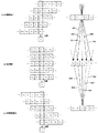
次に図6を用いて像シフトおよび像生成を模式的に示し、像の再構成によるコントラスト計算の有用性について述べる。 Next, image shift and image generation are schematically shown in FIG. 6, and the usefulness of contrast calculation by image reconstruction will be described.
図6において、図6(b)は実際に撮像素子6が存在して画像を取得した面を、図6(a)は図6(b)よりも被写体側の再構成面(再構成面1)を、図6(c)は図6(b)よりも被写体側から遠い側の再構成面(再構成面2)をそれぞれ示している。なお、上述のように同図においては、説明を明瞭とするために瞳分割方向および画素配列はそれぞれ一次元としている。 6B, FIG. 6B shows the surface where the image sensor 6 actually exists and the image is acquired, and FIG. 6A shows the reconstruction surface (reconstruction surface 1) closer to the subject than FIG. 6B. 6C shows a reconstruction surface (reconstruction surface 2) on the side farther from the subject side than FIG. 6B. As described above, in the figure, the pupil division direction and the pixel array are each one-dimensional for the sake of clarity.
図6(b)において、X1,i、X2,i、X3,i、X4,i、X5,i、はそれぞれ瞳領域1、2、3、4、5を通過してマイクロレンズXiに入射して得られたデータ(画像データ)を示している。すなわち、添え字のうち前半は通過する瞳領域を、後半はマイクロレンズの番号を示している。物理的な位置との関係においては、X1,iは図3(c)の321領域から得られるデータを、X2,iは図3(c)の322領域から得られるデータを、以下添え字の3、4、5は領域323、324、325に対応していることを示している。
In FIG. 6B, X 1, i , X 2, i , X 3, i , X 4, i , X 5, i pass through the
取得面での画像を生成するためには、図6(b)に示すように、マイクロレンズXiに入射したデータ(輝度)を加算すればよい。具体的には、Si = X1,I + X2,i + X3,i + X4,i + X5,iでXiに入射した光の角度方向の積分値を得ることができる。これをすべてのマイクロレンズについて行なうことにより通常のカメラと同様の像が生成される。 To generate an image in the acquisition plane, as shown in FIG. 6 (b), may be added to data (luminance) incident on the microlens X i. Specifically, the integrated value in the angular direction of the light incident on X i can be obtained with S i = X 1, I + X 2, i + X 3, i + X 4, i + X 5, i . By performing this operation for all the microlenses, an image similar to that of a normal camera is generated.
次に再構成面1での像の生成方法を考える。図3で説明したように、本実施例の撮影光学系は、各画素に入射する光束を特定の瞳領域に限定しているために、入射角度が既知である。この角度に沿って再構成面での各画素の位置を再構成する。具体的にはX1,iのように瞳領域の添え字が1のものは図6の右側の図において641で示すような角度で入射しているとする。以下瞳領域の添え字2,3,4,5はそれぞれ642,643,644,645に対応しているとする。この時、再構成面1でのマイクロレンズXiに入射した光束は、取得面においては、Xi-2からXi+2(一次元)に分散して入射していることになる。より具体的には、X1,i-2、X2,i-1、X3,i、X4,i+1、X5,i+2に分散している。Xiに限らず再構成面1での像を復元するためには、入射角度に応じて像をシフトさせて加算すれば良いことが分かる。再構成面1での像を生成するためには、瞳領域の添え字が1のものは右に2画素シフト、瞳領域の添え字が2のものは右に1画素シフト、瞳領域の添え字が3のものはシフトなしとする。さらに、瞳領域の添え字が4のものは左に1画素シフト、瞳領域の添え字が5のものは左に2画素シフトとすることで入射角度に応じたシフトを与えることができる。その後図6(a)に示す縦方向の加算によって再構成面1でのデータを得ることができる。具体的には、Si = X1,i-2 + X2,i-1 + X3,i + X4,i+1 + X5,i+2で再構成面1において、Xiに入射した光の角度方向の積分値を得ることができる。これにより再構成面での画像が得られた。
Next, a method for generating an image on the
ここで、再構成面1において、Xiに輝点があったとすると、取得面においてはX1,i-2、X2,i-1、X3,i、X4,i+1、X5,i+2に分散していわゆるボケ状態にある。しかしながら、上述した再構成面1での像を生成すると、再びXiに輝点が生成されコントラストの高い像が得られる。すなわち像を再構成してコントラストを計算することで、いわゆるコントラストAFを行うことが可能となる。
Here, in the
また、図6(c)から分かるように、再構成面2においても再構成面と全く同様の方法で像を生成することができる。再構成面を配置する方向が異なると(物体に対して反対側という意味)シフトさせる方向を反転させれば良いだけである。
Further, as can be seen from FIG. 6C, an image can be generated on the
以上に説明したように、本実施例によれば、撮像装置の構造に応じて決まる結像位置に応じて位相差AFとコントラストAFを使い分けて高いAF精度を維持することが可能な撮像装置を提供するこができる。しかも、本発明の撮像装置では、コントラストAFの精度が保証されない結像位置では位相差AFのみが実行される。結果として、高速かつピント精度の高いAFを行うことを可能にした撮像装置を提供することが出来る。また、AF用の光束情報を得るために必要な撮像動作は(撮像素子の蓄積、読み出し)、一回だけでよいため、合焦制御動作のさらなる高速化が可能となる。 As described above, according to the present embodiment, the imaging apparatus capable of maintaining high AF accuracy by properly using the phase difference AF and the contrast AF according to the imaging position determined according to the structure of the imaging apparatus. Can be provided. In addition, in the imaging apparatus of the present invention, only the phase difference AF is executed at the imaging position where the accuracy of contrast AF is not guaranteed. As a result, it is possible to provide an imaging apparatus that can perform AF with high speed and high focus accuracy. In addition, since the imaging operation necessary to obtain the luminous flux information for AF (accumulation and reading of the imaging device) is only required once, the focusing control operation can be further speeded up.
上述した実施形態において図2及び図4−5示した各処理は、各処理の機能を実現する為のプログラムをメモリから読み出して制御系のCPUが実行することによりその機能を実現させるものである。 2 and 4-5 in the above-described embodiment, the function is realized by reading a program for realizing the function of each process from the memory and executing it by the CPU of the control system. .
尚、上述した構成に限定されるものではなく、図2及び図4−5に示した各処理の全部または一部の機能を専用のハードウェアにより実現してもよい。また、上述したメモリは、光磁気ディスク装置、フラッシュメモリ等の不揮発性のメモリや、CD−ROM等の読み出しのみが可能な記録媒体、RAM以外の揮発性のメモリが可能である。また、それらの組合せによるコンピュータ読み取り、書き込み可能な記録媒体より構成されていてもよい。 Note that the present invention is not limited to the above-described configuration, and all or some of the functions shown in FIGS. 2 and 4-5 may be realized by dedicated hardware. The memory described above can be a non-volatile memory such as a magneto-optical disk device or a flash memory, a recording medium such as a CD-ROM that can only be read, and a volatile memory other than a RAM. Moreover, you may comprise from the computer-readable / writable recording medium by those combination.
また、図2及び図4−5に示した各処理の機能を実現する為のプログラムをコンピュータ読み取り可能な記録媒体に記録して、この記録媒体に記録されたプログラムをコンピュータシステムに読み込ませ、実行することにより各処理を行っても良い。なお、ここでいう「コンピュータシステム」とは、OSや周辺機器等のハードウェアを含むものとする。具体的には、記憶媒体から読み出されたプログラムが、コンピュータに挿入された機能拡張ボードやコンピュータに接続された機能拡張ユニットに備わるメモリに書きこまれた場合である。このプログラムの指示に基づき、機能拡張ボードや機能拡張ユニットに備わるCPUなどが実際の処理の一部または全部を行い、その処理によって前述した実施形態の機能が実現される場合も本件発明に含まれる。 2 and 4-5 are recorded in a computer-readable recording medium, and the program recorded in the recording medium is read into a computer system and executed. Thus, each process may be performed. Here, the “computer system” includes an OS and hardware such as peripheral devices. Specifically, the program read from the storage medium is written in a memory provided in a function expansion board inserted into the computer or a function expansion unit connected to the computer. The present invention also includes the case where the CPU of the function expansion board or function expansion unit performs part or all of the actual processing based on the instructions of the program and the functions of the above-described embodiments are realized by the processing. .
また、「コンピュータ読み取り可能な記録媒体」とは、フレキシブルディスク、光磁気ディスク、ROM、CD−ROM等の可搬媒体、コンピュータシステムに内蔵されるハードディスク等の記憶装置のことをいう。また、インターネット等のネットワークや電話回線等の通信回線を介してプログラムが送信された場合のサーバやクライアントとなるコンピュータシステム内部の揮発メモリ(RAM)のように、一定時間プログラムを保持しているものも含む。 The “computer-readable recording medium” refers to a storage device such as a flexible medium, a magneto-optical disk, a portable medium such as a ROM and a CD-ROM, and a hard disk incorporated in a computer system. In addition, a program that holds a program for a certain period of time, such as a volatile memory (RAM) in a computer system serving as a server or client when the program is transmitted via a network such as the Internet or a communication line such as a telephone line Including.
また、上記プログラムは、このプログラムを記憶装置等に格納したコンピュータシステムから、伝送媒体を介して、あるいは、伝送媒体中の伝送波により他のコンピュータシステムに伝送されてもよい。ここで、プログラムを伝送する「伝送媒体」は、インターネット等のネットワーク(通信網)や電話回線等の通信回線(通信線)のように情報を伝送する機能を有する媒体のことをいう。 The program may be transmitted from a computer system storing the program in a storage device or the like to another computer system via a transmission medium or by a transmission wave in the transmission medium. Here, the “transmission medium” for transmitting the program refers to a medium having a function of transmitting information, such as a network (communication network) such as the Internet or a communication line (communication line) such as a telephone line.
また、上記プログラムは、前述した機能の一部を実現する為のものであっても良い。さらに、前述した機能をコンピュータシステムに既に記録されているプログラムとの組合せで実現できるもの、いわゆる差分ファイル(差分プログラム)であっても良い。 The program may be for realizing a part of the functions described above. Furthermore, what can implement | achieve the function mentioned above in combination with the program already recorded on the computer system, and what is called a difference file (difference program) may be sufficient.
また、上記のプログラムを記録したコンピュータ読み取り可能な記録媒体等のプログラムプロダクトも本発明の実施形態として適用することができる。上記のプログラム、記録媒体、伝送媒体およびプログラムプロダクトは、本発明の範疇に含まれる。 A program product such as a computer-readable recording medium in which the above program is recorded can also be applied as an embodiment of the present invention. The above program, recording medium, transmission medium, and program product are included in the scope of the present invention.
以上、本発明の好ましい実施形態について説明したが、本発明はこれらの実施形態に限定されず、その要旨の範囲内で種々の変形及び変更が可能である。 As mentioned above, although preferable embodiment of this invention was described, this invention is not limited to these embodiment, A various deformation | transformation and change are possible within the range of the summary.
Claims (12)
前記各マイクロレンズに対応する複数の前記光電変換部からの画像信号をシフトして、ピント位置の異なる画像を生成する像生成手段と、
前記像生成手段により生成された前記画像のコントラストの評価値を計算し、前記コントラストの評価値に基づいてコントラストピント位置を決定するコントラスト評価手段と、
前記各マイクロレンズに対応する複数の光電変換部から得られる画像信号間の相関の評価値を計算し、前記相関の評価値に基づいて相関ピント位置を決定する相関計算手段と、
前記相関ピント位置と、前記像生成手段によりシフトが可能なピント評価位置の範囲とを比較し、前記相関ピント位置の絶対値が前記像生成手段によりシフトが可能なピント評価位置の範囲の絶対値よりも大きいとき、前記コントラスト評価手段による決定を省略して前記相関計算手段により決定された前記相関ピント位置に基づいて被写体のピント評価位置を決定し、前記相関ピント位置の絶対値が前記像生成手段によりシフトが可能なピント評価位置の範囲の絶対値以下のとき、前記コントラスト評価手段により決定された前記コントラストピント位置に基づいて前記被写体のピント評価値を決定するピント評価手段と、
を備えることを特徴とする撮像装置。 In an imaging apparatus including a plurality of microlenses and an imaging element that outputs a plurality of photoelectric conversion units corresponding to each of the plurality of microlenses,
Image generating means for generating images with different focus positions by shifting image signals from the plurality of photoelectric conversion units corresponding to the microlenses,
A contrast evaluation unit that calculates a contrast evaluation value of the image generated by the image generation unit and determines a contrast focus position based on the contrast evaluation value;
Correlation calculation means for calculating an evaluation value of correlation between image signals obtained from a plurality of photoelectric conversion units corresponding to each microlens, and determining a correlation focus position based on the evaluation value of the correlation;
The correlation focus position is compared with a range of focus evaluation positions that can be shifted by the image generation means, and the absolute value of the correlation focus position is an absolute value of the range of focus evaluation positions that can be shifted by the image generation means. Is larger than the contrast evaluation means, the focus evaluation position of the subject is determined based on the correlation focus position determined by the correlation calculation means , and the absolute value of the correlation focus position is the image generation A focus evaluation unit that determines a focus evaluation value of the subject based on the contrast focus position determined by the contrast evaluation unit when the absolute value of a range of a focus evaluation position that can be shifted by the unit is equal to or less than
An imaging apparatus comprising:
前記複数のマイクロレンズは、各マイクロレンズに対応して複数の画素グループに分割し、前記マイクロレンズは対応する画素グループの各画素を前記撮影レンズの異なる射出瞳領域からの光束に対応させることを特徴とする請求項1乃至4のいずれか一項に記載の撮像装置。 A photographic lens
The plurality of microlenses are divided into a plurality of pixel groups corresponding to each microlens, and the microlens associates each pixel of the corresponding pixel group with a light flux from a different exit pupil region of the photographing lens. The imaging apparatus according to claim 1, wherein the imaging apparatus is characterized.
前記各マイクロレンズに対応する複数の前記光電変換部からの画像信号をシフトして、ピント位置の異なる画像を生成する像生成ステップと、
前記像生成ステップで生成された前記画像のコントラストの評価値を計算し、前記コントラストの評価値に基づいてコントラストピント位置を決定するコントラスト評価ステップと、
前記各マイクロレンズに対応する複数の光電変換部から得られる画像信号間の相関の評価値を計算し、前記相関の評価値に基づいて相関ピント位置を決定する相関計算ステップと、
前記相関ピント位置と、前記像生成ステップによりシフトが可能なピント評価位置の範囲とを比較し、前記相関ピント位置の絶対値が前記像生成ステップによりシフトが可能なピント評価位置の範囲の絶対値よりも大きいとき、前記コントラスト評価ステップでの決定を省略して前記相関計算ステップで決定された前記相関ピント位置に基づいて被写体のピント評価位置を決定し、前記相関ピント位置の絶対値が前記像生成ステップによりシフトが可能なピント評価位置の範囲の絶対値以下のとき、前記コントラスト評価ステップで決定された前記コントラストピント位置に基づいて前記被写体のピント評価値を決定するピント評価ステップを備えたことを特徴とする制御方法。 In a control method of an imaging apparatus including a plurality of microlenses and an imaging element that outputs a plurality of photoelectric conversion units corresponding to each of the plurality of microlenses,
An image generation step of generating an image having a different focus position by shifting image signals from the plurality of photoelectric conversion units corresponding to the microlenses,
A contrast evaluation step of calculating a contrast evaluation value of the image generated in the image generation step and determining a contrast focus position based on the contrast evaluation value;
A correlation calculation step of calculating an evaluation value of a correlation between image signals obtained from a plurality of photoelectric conversion units corresponding to each microlens, and determining a correlation focus position based on the evaluation value of the correlation;
The correlation focus position is compared with the range of focus evaluation positions that can be shifted by the image generation step, and the absolute value of the correlation focus position is the absolute value of the range of focus evaluation positions that can be shifted by the image generation step. Is greater than the contrast evaluation step, the focus evaluation position of the subject is determined based on the correlation focus position determined in the correlation calculation step, and the absolute value of the correlation focus position is the image. A focus evaluation step of determining a focus evaluation value of the subject based on the contrast focus position determined in the contrast evaluation step when the absolute value is equal to or less than a range of focus evaluation positions that can be shifted in the generation step A control method characterized by the above.
複数のマイクロレンズと、前記複数のマイクロレンズのそれぞれに複数の光電変換部が対応して画像信号を出力する撮像素子とを含む撮像装置において、
前記各マイクロレンズに対応する複数の前記光電変換部からの画像信号をシフトして、ピント位置の異なる画像を生成する像生成手段、
前記像生成手段により生成された前記画像のコントラストの評価値を計算し、前記コントラストの評価値に基づいてコントラストピント位置を決定するコントラスト評価手段と、
前記各マイクロレンズに対応する複数の光電変換部から得られる画像信号間の相関の評価値を計算し、前記相関の評価値に基づいて相関ピント位置を決定する相関計算手段、
前記相関ピント位置と、前記像生成手段によりシフトが可能なピント評価位置の範囲とを比較し、前記相関ピント位置の絶対値が前記像生成手段によりシフトが可能なピント評価位置の範囲の絶対値よりも大きいとき、前記コントラスト評価手段による決定を省略して前記相関計算手段により決定された前記相関ピント位置に基づいて被写体のピント評価位置を決定し、
前記相関ピント位置の絶対値が前記像生成手段によりシフトが可能なピント評価位置の範囲の絶対値以下のとき、前記コントラスト評価手段により決定された前記コントラストピント位置に基づいて前記被写体のピント評価値を決定するピント評価手段として機能させるプログラム。 Computer
In an imaging apparatus including a plurality of microlenses and an imaging element that outputs a plurality of photoelectric conversion units corresponding to each of the plurality of microlenses,
Image generating means for generating an image with different focus positions by shifting image signals from the plurality of photoelectric conversion units corresponding to the microlenses,
A contrast evaluation unit that calculates a contrast evaluation value of the image generated by the image generation unit and determines a contrast focus position based on the contrast evaluation value;
Correlation calculation means for calculating an evaluation value of correlation between image signals obtained from a plurality of photoelectric conversion units corresponding to each microlens, and determining a correlation focus position based on the evaluation value of the correlation;
The correlation focus position is compared with a range of focus evaluation positions that can be shifted by the image generation means, and the absolute value of the correlation focus position is an absolute value of the range of focus evaluation positions that can be shifted by the image generation means. Is greater than , determining the focus evaluation position of the subject based on the correlation focus position determined by the correlation calculation means, omitting the determination by the contrast evaluation means,
The focus evaluation value of the subject based on the contrast focus position determined by the contrast evaluation unit when the absolute value of the correlation focus position is equal to or smaller than the absolute value of the range of the focus evaluation position that can be shifted by the image generation unit A program that functions as a focus evaluation means for determining
Priority Applications (8)
| Application Number | Priority Date | Filing Date | Title |
|---|---|---|---|
| JP2011162093A JP6000520B2 (en) | 2011-07-25 | 2011-07-25 | Imaging apparatus and control method and program thereof |
| GB1400663.9A GB2506084B (en) | 2011-07-25 | 2012-07-24 | Image pickup apparatus, control method thereof, and program |
| US14/131,229 US9019424B2 (en) | 2011-07-25 | 2012-07-24 | Image pickup apparatus, control method thereof, and program |
| CN201280036923.1A CN103703401B (en) | 2011-07-25 | 2012-07-24 | Camera device and control method thereof |
| DE112012003105.9T DE112012003105B4 (en) | 2011-07-25 | 2012-07-24 | Image recording device and control method therefor, camera system control unit and control method therefor |
| PCT/JP2012/069276 WO2013015437A1 (en) | 2011-07-25 | 2012-07-24 | Image pickup apparatus, control method thereof, and program |
| RU2014106864/28A RU2562394C1 (en) | 2011-07-25 | 2012-07-24 | Shooting device, method and programme for its control |
| US14/657,250 US9279955B2 (en) | 2011-07-25 | 2015-03-13 | Image pickup apparatus, control method thereof, and program |
Applications Claiming Priority (1)
| Application Number | Priority Date | Filing Date | Title |
|---|---|---|---|
| JP2011162093A JP6000520B2 (en) | 2011-07-25 | 2011-07-25 | Imaging apparatus and control method and program thereof |
Publications (2)
| Publication Number | Publication Date |
|---|---|
| JP2013025246A JP2013025246A (en) | 2013-02-04 |
| JP6000520B2 true JP6000520B2 (en) | 2016-09-28 |
Family
ID=47601266
Family Applications (1)
| Application Number | Title | Priority Date | Filing Date |
|---|---|---|---|
| JP2011162093A Expired - Fee Related JP6000520B2 (en) | 2011-07-25 | 2011-07-25 | Imaging apparatus and control method and program thereof |
Country Status (7)
| Country | Link |
|---|---|
| US (2) | US9019424B2 (en) |
| JP (1) | JP6000520B2 (en) |
| CN (1) | CN103703401B (en) |
| DE (1) | DE112012003105B4 (en) |
| GB (1) | GB2506084B (en) |
| RU (1) | RU2562394C1 (en) |
| WO (1) | WO2013015437A1 (en) |
Families Citing this family (23)
| Publication number | Priority date | Publication date | Assignee | Title |
|---|---|---|---|---|
| JP2014164258A (en) * | 2013-02-27 | 2014-09-08 | Nikon Corp | Focus detection device and amount of image deviation detection device |
| EP2848974B1 (en) | 2012-05-07 | 2018-11-21 | Nikon Corporation | Focus detection device |
| JP5914192B2 (en) * | 2012-06-11 | 2016-05-11 | キヤノン株式会社 | Imaging apparatus and control method thereof |
| JP5775976B2 (en) * | 2012-11-22 | 2015-09-09 | 富士フイルム株式会社 | Imaging apparatus, defocus amount calculation method, and imaging optical system |
| JP2014149381A (en) * | 2013-01-31 | 2014-08-21 | Sony Corp | Image acquisition apparatus and image acquisition method |
| JP6230239B2 (en) * | 2013-02-14 | 2017-11-15 | キヤノン株式会社 | Image processing apparatus, imaging apparatus, image processing method, image processing program, and storage medium |
| WO2014155806A1 (en) * | 2013-03-29 | 2014-10-02 | 富士フイルム株式会社 | Imaging device, and focus control method |
| JP6334847B2 (en) * | 2013-04-17 | 2018-05-30 | キヤノン株式会社 | FOCUS DETECTION DEVICE, FOCUS DETECTION METHOD AND PROGRAM, AND IMAGING DEVICE |
| JP6239855B2 (en) | 2013-05-08 | 2017-11-29 | キヤノン株式会社 | Focus adjustment apparatus, focus adjustment method and program, and imaging apparatus |
| JP6239862B2 (en) | 2013-05-20 | 2017-11-29 | キヤノン株式会社 | Focus adjustment apparatus, focus adjustment method and program, and imaging apparatus |
| JP2014235184A (en) * | 2013-05-30 | 2014-12-15 | 株式会社ニコン | Focus detection device, focus adjustment device and imaging device |
| JP6285683B2 (en) * | 2013-10-01 | 2018-02-28 | キヤノン株式会社 | Imaging apparatus and control method thereof |
| JP2015129846A (en) * | 2014-01-07 | 2015-07-16 | キヤノン株式会社 | Imaging apparatus and control method thereof |
| WO2015146229A1 (en) * | 2014-03-25 | 2015-10-01 | 富士フイルム株式会社 | Imaging device and focusing control method |
| JP2015194736A (en) | 2014-03-28 | 2015-11-05 | キヤノン株式会社 | Imaging apparatus and control method thereof |
| JP6381266B2 (en) | 2014-04-15 | 2018-08-29 | キヤノン株式会社 | IMAGING DEVICE, CONTROL DEVICE, CONTROL METHOD, PROGRAM, AND STORAGE MEDIUM |
| JP2016038414A (en) | 2014-08-05 | 2016-03-22 | キヤノン株式会社 | FOCUS DETECTION DEVICE, ITS CONTROL METHOD, AND IMAGING DEVICE |
| JP2016133595A (en) | 2015-01-19 | 2016-07-25 | キヤノン株式会社 | Controller, imaging device, control method, program, and storage medium |
| TWI561908B (en) * | 2015-03-27 | 2016-12-11 | Vivotek Inc | Auto focus method and apparatus using the same method |
| CN105007420B (en) * | 2015-07-14 | 2018-09-04 | 广东欧珀移动通信有限公司 | A kind of focusing method and mobile terminal |
| JP6800725B2 (en) * | 2016-12-06 | 2020-12-16 | キヤノン株式会社 | Focus detector, its control method, program and storage medium |
| JP2018128678A (en) * | 2018-02-14 | 2018-08-16 | 株式会社ニコン | Imaging device |
| JP2020052379A (en) * | 2018-09-28 | 2020-04-02 | エスゼット ディージェイアイ テクノロジー カンパニー リミテッドSz Dji Technology Co.,Ltd | Controller, imaging device, mobile body, method for control, and program |
Family Cites Families (82)
| Publication number | Priority date | Publication date | Assignee | Title |
|---|---|---|---|---|
| JPH07199052A (en) | 1993-12-28 | 1995-08-04 | Olympus Optical Co Ltd | Focus detecting method and distance measuring method |
| CN1189774C (en) * | 1998-08-26 | 2005-02-16 | 中国科学院光电技术研究所 | Optical Wavefront Sensor |
| US6750437B2 (en) * | 2000-08-28 | 2004-06-15 | Canon Kabushiki Kaisha | Image pickup apparatus that suitably adjusts a focus |
| KR100900485B1 (en) * | 2002-10-26 | 2009-06-03 | 삼성디지털이미징 주식회사 | Image sensing means for digital camera with improved structure and digital camera using same |
| JP3823921B2 (en) * | 2002-12-27 | 2006-09-20 | コニカミノルタフォトイメージング株式会社 | Imaging device |
| JP4324402B2 (en) * | 2003-04-08 | 2009-09-02 | Hoya株式会社 | Camera autofocus device |
| JP2004354581A (en) * | 2003-05-28 | 2004-12-16 | Minolta Co Ltd | Imaging device |
| JP2005195786A (en) * | 2004-01-06 | 2005-07-21 | Canon Inc | Focus detection device and optical instrument using the same |
| US7502065B2 (en) * | 2004-06-16 | 2009-03-10 | Hoya Corporation | Focus detection method and focus detection apparatus |
| JP2006106435A (en) * | 2004-10-06 | 2006-04-20 | Canon Inc | Optical equipment |
| JP4826152B2 (en) | 2005-06-23 | 2011-11-30 | 株式会社ニコン | Image composition method and imaging apparatus |
| JP4910366B2 (en) * | 2005-11-09 | 2012-04-04 | 株式会社ニコン | Focus detection apparatus, optical system, and focus detection method |
| KR101156681B1 (en) * | 2005-12-12 | 2012-06-14 | 삼성전자주식회사 | Automatic focusing method using variable noise level within digital image processing apparatus |
| JP4720508B2 (en) * | 2006-01-05 | 2011-07-13 | 株式会社ニコン | Imaging device and imaging apparatus |
| US7792420B2 (en) * | 2006-03-01 | 2010-09-07 | Nikon Corporation | Focus adjustment device, imaging device and focus adjustment method |
| US7751700B2 (en) * | 2006-03-01 | 2010-07-06 | Nikon Corporation | Focus adjustment device, imaging device and focus adjustment method |
| JP2007310009A (en) * | 2006-05-16 | 2007-11-29 | Olympus Imaging Corp | Digital camera and camera system |
| JP4321579B2 (en) * | 2006-11-28 | 2009-08-26 | ソニー株式会社 | Imaging device |
| JP5247044B2 (en) * | 2007-02-16 | 2013-07-24 | キヤノン株式会社 | Imaging device |
| JP4973273B2 (en) * | 2007-03-28 | 2012-07-11 | 株式会社ニコン | Digital camera |
| JP5191168B2 (en) * | 2007-06-11 | 2013-04-24 | 株式会社ニコン | Focus detection apparatus and imaging apparatus |
| EP2028843B1 (en) * | 2007-08-21 | 2013-10-23 | Ricoh Company, Ltd. | Focusing device and imaging apparatus using the same |
| JP5092685B2 (en) * | 2007-10-23 | 2012-12-05 | 株式会社ニコン | Imaging device and imaging apparatus |
| JP2009175279A (en) * | 2008-01-22 | 2009-08-06 | Olympus Imaging Corp | Camera system |
| JP5130178B2 (en) * | 2008-03-17 | 2013-01-30 | 株式会社リコー | Focal length detection apparatus, imaging apparatus, imaging method, and camera |
| JP5089515B2 (en) | 2008-07-15 | 2012-12-05 | キヤノン株式会社 | Focus adjustment device, imaging device, interchangeable lens, conversion coefficient calibration method, conversion coefficient calibration program |
| JP5317562B2 (en) * | 2008-07-17 | 2013-10-16 | キヤノン株式会社 | Phase difference detection device, imaging device, phase difference detection method, phase difference detection program |
| KR20100013859A (en) * | 2008-08-01 | 2010-02-10 | 삼성디지털이미징 주식회사 | Apparatus and method for adjusting focus using modulation transfer fuction of lens in digital image processing device |
| JP5161702B2 (en) * | 2008-08-25 | 2013-03-13 | キヤノン株式会社 | Imaging apparatus, imaging system, and focus detection method |
| JP5097077B2 (en) | 2008-10-10 | 2012-12-12 | キヤノン株式会社 | Imaging apparatus, control method thereof, and program |
| RU2389050C1 (en) * | 2008-10-30 | 2010-05-10 | Общество с ограниченной ответственностью Научно-Производственная компания "СенсорИС" | Automatic focusing method |
| JP5489641B2 (en) * | 2008-11-11 | 2014-05-14 | キヤノン株式会社 | Focus detection apparatus and control method thereof |
| JP2010128122A (en) * | 2008-11-27 | 2010-06-10 | Olympus Corp | Imaging apparatus |
| JP5230388B2 (en) * | 2008-12-10 | 2013-07-10 | キヤノン株式会社 | Focus detection apparatus and control method thereof |
| JP5195506B2 (en) * | 2009-02-24 | 2013-05-08 | 株式会社ニコン | Imaging apparatus and image composition method |
| JP4766133B2 (en) * | 2009-03-11 | 2011-09-07 | 株式会社ニコン | Imaging device |
| JP5322783B2 (en) * | 2009-06-05 | 2013-10-23 | キヤノン株式会社 | IMAGING DEVICE AND CONTROL METHOD OF IMAGING DEVICE |
| JP5393300B2 (en) * | 2009-07-06 | 2014-01-22 | キヤノン株式会社 | Imaging device |
| JP2011017800A (en) * | 2009-07-07 | 2011-01-27 | Canon Inc | Focus detection apparatus |
| JP2011023812A (en) * | 2009-07-13 | 2011-02-03 | Nikon Corp | Image recorder and image display device |
| JP5517514B2 (en) * | 2009-07-16 | 2014-06-11 | キヤノン株式会社 | Imaging apparatus and control method thereof |
| JP5045801B2 (en) * | 2009-09-09 | 2012-10-10 | 株式会社ニコン | Focus detection device, photographing lens unit, imaging device, and camera system |
| CN102598652B (en) * | 2009-10-30 | 2015-08-12 | 佳能株式会社 | Messaging device and method |
| JP2011139282A (en) | 2009-12-28 | 2011-07-14 | Sony Corp | Image processing apparatus, imaging apparatus, image processing method, and program |
| JP5429358B2 (en) * | 2010-03-01 | 2014-02-26 | コニカミノルタ株式会社 | Ghost detection device, imaging device using the same, ghost detection method, and ghost removal method |
| JP2011221253A (en) * | 2010-04-08 | 2011-11-04 | Sony Corp | Imaging apparatus, solid-state image sensor, imaging method and program |
| JP2011221254A (en) * | 2010-04-08 | 2011-11-04 | Sony Corp | Imaging device, solid-state image pick-up element, imaging method and program |
| JP5773583B2 (en) * | 2010-06-11 | 2015-09-02 | キヤノン株式会社 | Imaging apparatus, control method therefor, and computer program |
| JP2012032723A (en) * | 2010-08-03 | 2012-02-16 | Sony Corp | Imaging device, imaging element, imaging method, and program |
| JP5606208B2 (en) | 2010-08-03 | 2014-10-15 | キヤノン株式会社 | Focus detection apparatus and imaging apparatus |
| JP2012043939A (en) * | 2010-08-18 | 2012-03-01 | Sony Corp | Imaging element and imaging apparatus |
| JP5753371B2 (en) * | 2010-11-25 | 2015-07-22 | キヤノン株式会社 | Imaging apparatus and control method thereof |
| JP5623254B2 (en) * | 2010-11-29 | 2014-11-12 | キヤノン株式会社 | Imaging apparatus and control method thereof |
| JP5743514B2 (en) * | 2010-12-08 | 2015-07-01 | キヤノン株式会社 | Imaging apparatus, control method thereof, and program |
| JP5165099B2 (en) * | 2010-12-10 | 2013-03-21 | キヤノン株式会社 | Imaging device and lens unit |
| JP5709532B2 (en) * | 2011-01-05 | 2015-04-30 | キヤノン株式会社 | Automatic focusing device, lens device having the same, and imaging system |
| JP2012145664A (en) * | 2011-01-11 | 2012-08-02 | Sony Corp | Image processing system, imaging apparatus, image processing method and program |
| JP5954933B2 (en) * | 2011-03-29 | 2016-07-20 | キヤノン株式会社 | Imaging device and lens device |
| JP5825817B2 (en) * | 2011-04-01 | 2015-12-02 | キヤノン株式会社 | Solid-state imaging device and imaging apparatus |
| JP5818514B2 (en) * | 2011-05-27 | 2015-11-18 | キヤノン株式会社 | Image processing apparatus, image processing method, and program |
| JP6021306B2 (en) * | 2011-07-25 | 2016-11-09 | キヤノン株式会社 | Imaging apparatus and control method thereof |
| JP5822613B2 (en) * | 2011-09-12 | 2015-11-24 | キヤノン株式会社 | Image processing apparatus and image processing method |
| JP5898501B2 (en) * | 2012-01-13 | 2016-04-06 | キヤノン株式会社 | Image processing apparatus, imaging apparatus, control method, program, and recording medium |
| JP5914055B2 (en) * | 2012-03-06 | 2016-05-11 | キヤノン株式会社 | Imaging device |
| JP5917207B2 (en) * | 2012-03-14 | 2016-05-11 | キヤノン株式会社 | Focus adjustment device |
| US9451147B2 (en) * | 2012-06-11 | 2016-09-20 | Canon Kabushiki Kaisha | Image processing apparatus, image processing method, image pickup apparatus, method of controlling image pickup apparatus, and non-transitory computer-readable storage medium |
| JP6029380B2 (en) * | 2012-08-14 | 2016-11-24 | キヤノン株式会社 | Image processing apparatus, imaging apparatus including image processing apparatus, image processing method, and program |
| JP6033038B2 (en) * | 2012-10-26 | 2016-11-30 | キヤノン株式会社 | FOCUS DETECTION DEVICE, IMAGING DEVICE, IMAGING SYSTEM, AND FOCUS DETECTION METHOD |
| JP6124564B2 (en) * | 2012-11-21 | 2017-05-10 | キヤノン株式会社 | Focus detection apparatus and method, and imaging apparatus |
| WO2014083752A1 (en) * | 2012-11-30 | 2014-06-05 | パナソニック株式会社 | Alternate viewpoint image generating device and alternate viewpoint image generating method |
| JP2014126710A (en) * | 2012-12-26 | 2014-07-07 | Canon Inc | Automatic focus detection device, control method therefor, and image capturing device |
| JP6346439B2 (en) * | 2013-01-07 | 2018-06-20 | キヤノン株式会社 | Imaging apparatus and control method thereof |
| JP6045362B2 (en) * | 2013-01-17 | 2016-12-14 | オリンパス株式会社 | Imaging apparatus and focus detection method |
| JP6271952B2 (en) * | 2013-01-23 | 2018-01-31 | キヤノン株式会社 | Imaging device |
| JP2014179939A (en) * | 2013-03-15 | 2014-09-25 | Sony Corp | Signal processing device, and signal processing method |
| JP6532119B2 (en) * | 2013-04-30 | 2019-06-19 | キヤノン株式会社 | Image pickup apparatus and control method thereof |
| JP6100089B2 (en) * | 2013-05-17 | 2017-03-22 | キヤノン株式会社 | Image processing apparatus, image processing method, and program |
| JP6239862B2 (en) * | 2013-05-20 | 2017-11-29 | キヤノン株式会社 | Focus adjustment apparatus, focus adjustment method and program, and imaging apparatus |
| JP6288952B2 (en) * | 2013-05-28 | 2018-03-07 | キヤノン株式会社 | Imaging apparatus and control method thereof |
| JP6372983B2 (en) * | 2013-09-02 | 2018-08-15 | キヤノン株式会社 | FOCUS DETECTION DEVICE, ITS CONTROL METHOD, AND IMAGING DEVICE |
| JP6351231B2 (en) * | 2013-10-18 | 2018-07-04 | キヤノン株式会社 | IMAGING DEVICE, IMAGING SYSTEM, IMAGING DEVICE CONTROL METHOD, PROGRAM, AND STORAGE MEDIUM |
| JP2015094925A (en) * | 2013-11-14 | 2015-05-18 | キヤノン株式会社 | Focus adjustment device, focus adjustment method and program, and imaging device having focus adjustment device |
-
2011
- 2011-07-25 JP JP2011162093A patent/JP6000520B2/en not_active Expired - Fee Related
-
2012
- 2012-07-24 DE DE112012003105.9T patent/DE112012003105B4/en not_active Expired - Fee Related
- 2012-07-24 WO PCT/JP2012/069276 patent/WO2013015437A1/en not_active Ceased
- 2012-07-24 GB GB1400663.9A patent/GB2506084B/en not_active Expired - Fee Related
- 2012-07-24 RU RU2014106864/28A patent/RU2562394C1/en active
- 2012-07-24 US US14/131,229 patent/US9019424B2/en not_active Expired - Fee Related
- 2012-07-24 CN CN201280036923.1A patent/CN103703401B/en active Active
-
2015
- 2015-03-13 US US14/657,250 patent/US9279955B2/en active Active
Also Published As
| Publication number | Publication date |
|---|---|
| GB201400663D0 (en) | 2014-03-05 |
| US9019424B2 (en) | 2015-04-28 |
| CN103703401B (en) | 2016-01-27 |
| GB2506084A (en) | 2014-03-19 |
| GB2506084B (en) | 2018-04-04 |
| RU2562394C1 (en) | 2015-09-10 |
| JP2013025246A (en) | 2013-02-04 |
| US20140146221A1 (en) | 2014-05-29 |
| DE112012003105B4 (en) | 2020-04-02 |
| DE112012003105T5 (en) | 2014-04-24 |
| WO2013015437A1 (en) | 2013-01-31 |
| CN103703401A (en) | 2014-04-02 |
| US20150185434A1 (en) | 2015-07-02 |
| US9279955B2 (en) | 2016-03-08 |
Similar Documents
| Publication | Publication Date | Title |
|---|---|---|
| JP6000520B2 (en) | Imaging apparatus and control method and program thereof | |
| JP6405243B2 (en) | Focus detection apparatus and control method thereof | |
| JP6021306B2 (en) | Imaging apparatus and control method thereof | |
| JP5914192B2 (en) | Imaging apparatus and control method thereof | |
| US9602716B2 (en) | Focus-detection device, method for controlling the same, and image capture apparatus | |
| KR20070086061A (en) | Camera and Camera Image Processing Method | |
| WO2013171840A9 (en) | Imaging apparatus, and imaging apparatus control method | |
| JP6762710B2 (en) | Imaging device and its control method | |
| JP5893412B2 (en) | Imaging apparatus and control method thereof | |
| JP6032967B2 (en) | IMAGING DEVICE, LENS DEVICE, AND IMAGING DEVICE CONTROL METHOD | |
| JP5211680B2 (en) | Autofocus device, autofocus method selection method, and program | |
| JP2006251065A (en) | Hybrid AF camera | |
| JP2016099416A (en) | Imaging device | |
| JP5968081B2 (en) | Imaging apparatus and control method thereof | |
| JP2013113967A (en) | Imaging apparatus, control method thereof, and program | |
| JP2014032311A (en) | Distance measuring device, imaging apparatus having the same, control method for imaging device, and control program | |
| JP2014029429A (en) | Imaging device, control method, and program | |
| JP7337566B2 (en) | IMAGING DEVICE, IMAGE PROCESSING METHOD, AND PROGRAM | |
| JP2006140797A (en) | Image processing apparatus and image processing method | |
| JP6144880B2 (en) | Display device, display method, and imaging device including the display device | |
| JP2014149460A (en) | Imaging apparatus and method for controlling the same | |
| JP2015025960A (en) | Focus detection system, focus detection method and program, and imaging apparatus | |
| JP2017011628A (en) | Imaging device | |
| JP2004170780A (en) | Lens focusing device |
Legal Events
| Date | Code | Title | Description |
|---|---|---|---|
| RD05 | Notification of revocation of power of attorney |
Free format text: JAPANESE INTERMEDIATE CODE: A7425 Effective date: 20130701 |
|
| A621 | Written request for application examination |
Free format text: JAPANESE INTERMEDIATE CODE: A621 Effective date: 20140722 |
|
| A131 | Notification of reasons for refusal |
Free format text: JAPANESE INTERMEDIATE CODE: A131 Effective date: 20150709 |
|
| A521 | Request for written amendment filed |
Free format text: JAPANESE INTERMEDIATE CODE: A523 Effective date: 20150907 |
|
| A131 | Notification of reasons for refusal |
Free format text: JAPANESE INTERMEDIATE CODE: A131 Effective date: 20160209 |
|
| A521 | Request for written amendment filed |
Free format text: JAPANESE INTERMEDIATE CODE: A523 Effective date: 20160323 |
|
| TRDD | Decision of grant or rejection written | ||
| A01 | Written decision to grant a patent or to grant a registration (utility model) |
Free format text: JAPANESE INTERMEDIATE CODE: A01 Effective date: 20160804 |
|
| A61 | First payment of annual fees (during grant procedure) |
Free format text: JAPANESE INTERMEDIATE CODE: A61 Effective date: 20160831 |
|
| R151 | Written notification of patent or utility model registration |
Ref document number: 6000520 Country of ref document: JP Free format text: JAPANESE INTERMEDIATE CODE: R151 |
|
| LAPS | Cancellation because of no payment of annual fees |