JP6239862B2 - Focus adjustment apparatus, focus adjustment method and program, and imaging apparatus - Google Patents
Focus adjustment apparatus, focus adjustment method and program, and imaging apparatus Download PDFInfo
- Publication number
- JP6239862B2 JP6239862B2 JP2013106195A JP2013106195A JP6239862B2 JP 6239862 B2 JP6239862 B2 JP 6239862B2 JP 2013106195 A JP2013106195 A JP 2013106195A JP 2013106195 A JP2013106195 A JP 2013106195A JP 6239862 B2 JP6239862 B2 JP 6239862B2
- Authority
- JP
- Japan
- Prior art keywords
- focus detection
- focus
- defocus amount
- pixel
- signal
- Prior art date
- Legal status (The legal status is an assumption and is not a legal conclusion. Google has not performed a legal analysis and makes no representation as to the accuracy of the status listed.)
- Active
Links
- 238000003384 imaging method Methods 0.000 title claims description 146
- 238000000034 method Methods 0.000 title claims description 106
- 238000001514 detection method Methods 0.000 claims description 421
- 210000001747 pupil Anatomy 0.000 claims description 99
- 230000003287 optical effect Effects 0.000 claims description 80
- 238000012545 processing Methods 0.000 claims description 55
- 230000008569 process Effects 0.000 claims description 52
- 238000011156 evaluation Methods 0.000 claims description 36
- 230000006870 function Effects 0.000 claims description 18
- 238000012937 correction Methods 0.000 claims description 8
- 230000007274 generation of a signal involved in cell-cell signaling Effects 0.000 claims description 4
- 238000006243 chemical reaction Methods 0.000 description 32
- 101150005874 DEF1 gene Proteins 0.000 description 10
- 230000004075 alteration Effects 0.000 description 10
- 238000010586 diagram Methods 0.000 description 9
- 238000003705 background correction Methods 0.000 description 8
- 230000005484 gravity Effects 0.000 description 8
- 230000002093 peripheral effect Effects 0.000 description 8
- 230000003595 spectral effect Effects 0.000 description 7
- 230000035945 sensitivity Effects 0.000 description 6
- 230000005540 biological transmission Effects 0.000 description 5
- 238000004891 communication Methods 0.000 description 5
- 230000004907 flux Effects 0.000 description 5
- 206010010071 Coma Diseases 0.000 description 3
- 201000009310 astigmatism Diseases 0.000 description 3
- 238000005286 illumination Methods 0.000 description 3
- 230000007423 decrease Effects 0.000 description 2
- 238000001914 filtration Methods 0.000 description 2
- 238000012546 transfer Methods 0.000 description 2
- 230000009471 action Effects 0.000 description 1
- 239000003086 colorant Substances 0.000 description 1
- 230000006835 compression Effects 0.000 description 1
- 238000007906 compression Methods 0.000 description 1
- 238000012790 confirmation Methods 0.000 description 1
- 238000000605 extraction Methods 0.000 description 1
- 230000004044 response Effects 0.000 description 1
- 238000002834 transmittance Methods 0.000 description 1
- 229910052724 xenon Inorganic materials 0.000 description 1
- FHNFHKCVQCLJFQ-UHFFFAOYSA-N xenon atom Chemical compound [Xe] FHNFHKCVQCLJFQ-UHFFFAOYSA-N 0.000 description 1
Images


Classifications
-
- H—ELECTRICITY
- H04—ELECTRIC COMMUNICATION TECHNIQUE
- H04N—PICTORIAL COMMUNICATION, e.g. TELEVISION
- H04N23/00—Cameras or camera modules comprising electronic image sensors; Control thereof
- H04N23/60—Control of cameras or camera modules
- H04N23/67—Focus control based on electronic image sensor signals
- H04N23/672—Focus control based on electronic image sensor signals based on the phase difference signals
-
- H—ELECTRICITY
- H04—ELECTRIC COMMUNICATION TECHNIQUE
- H04N—PICTORIAL COMMUNICATION, e.g. TELEVISION
- H04N23/00—Cameras or camera modules comprising electronic image sensors; Control thereof
- H04N23/60—Control of cameras or camera modules
- H04N23/67—Focus control based on electronic image sensor signals
- H04N23/673—Focus control based on electronic image sensor signals based on contrast or high frequency components of image signals, e.g. hill climbing method
-
- H—ELECTRICITY
- H04—ELECTRIC COMMUNICATION TECHNIQUE
- H04N—PICTORIAL COMMUNICATION, e.g. TELEVISION
- H04N25/00—Circuitry of solid-state image sensors [SSIS]; Control thereof
- H04N25/60—Noise processing, e.g. detecting, correcting, reducing or removing noise
- H04N25/61—Noise processing, e.g. detecting, correcting, reducing or removing noise the noise originating only from the lens unit, e.g. flare, shading, vignetting or "cos4"
- H04N25/615—Noise processing, e.g. detecting, correcting, reducing or removing noise the noise originating only from the lens unit, e.g. flare, shading, vignetting or "cos4" involving a transfer function modelling the optical system, e.g. optical transfer function [OTF], phase transfer function [PhTF] or modulation transfer function [MTF]
-
- H—ELECTRICITY
- H04—ELECTRIC COMMUNICATION TECHNIQUE
- H04N—PICTORIAL COMMUNICATION, e.g. TELEVISION
- H04N25/00—Circuitry of solid-state image sensors [SSIS]; Control thereof
- H04N25/70—SSIS architectures; Circuits associated therewith
- H04N25/703—SSIS architectures incorporating pixels for producing signals other than image signals
- H04N25/704—Pixels specially adapted for focusing, e.g. phase difference pixel sets
-
- H—ELECTRICITY
- H01—ELECTRIC ELEMENTS
- H01L—SEMICONDUCTOR DEVICES NOT COVERED BY CLASS H10
- H01L27/00—Devices consisting of a plurality of semiconductor or other solid-state components formed in or on a common substrate
- H01L27/14—Devices consisting of a plurality of semiconductor or other solid-state components formed in or on a common substrate including semiconductor components sensitive to infrared radiation, light, electromagnetic radiation of shorter wavelength or corpuscular radiation and specially adapted either for the conversion of the energy of such radiation into electrical energy or for the control of electrical energy by such radiation
- H01L27/144—Devices controlled by radiation
- H01L27/146—Imager structures
- H01L27/14601—Structural or functional details thereof
- H01L27/1462—Coatings
- H01L27/14621—Colour filter arrangements
-
- H—ELECTRICITY
- H01—ELECTRIC ELEMENTS
- H01L—SEMICONDUCTOR DEVICES NOT COVERED BY CLASS H10
- H01L27/00—Devices consisting of a plurality of semiconductor or other solid-state components formed in or on a common substrate
- H01L27/14—Devices consisting of a plurality of semiconductor or other solid-state components formed in or on a common substrate including semiconductor components sensitive to infrared radiation, light, electromagnetic radiation of shorter wavelength or corpuscular radiation and specially adapted either for the conversion of the energy of such radiation into electrical energy or for the control of electrical energy by such radiation
- H01L27/144—Devices controlled by radiation
- H01L27/146—Imager structures
- H01L27/14601—Structural or functional details thereof
- H01L27/14625—Optical elements or arrangements associated with the device
- H01L27/14627—Microlenses
-
- H—ELECTRICITY
- H01—ELECTRIC ELEMENTS
- H01L—SEMICONDUCTOR DEVICES NOT COVERED BY CLASS H10
- H01L27/00—Devices consisting of a plurality of semiconductor or other solid-state components formed in or on a common substrate
- H01L27/14—Devices consisting of a plurality of semiconductor or other solid-state components formed in or on a common substrate including semiconductor components sensitive to infrared radiation, light, electromagnetic radiation of shorter wavelength or corpuscular radiation and specially adapted either for the conversion of the energy of such radiation into electrical energy or for the control of electrical energy by such radiation
- H01L27/144—Devices controlled by radiation
- H01L27/146—Imager structures
- H01L27/14643—Photodiode arrays; MOS imagers
- H01L27/14645—Colour imagers
- H01L27/14647—Multicolour imagers having a stacked pixel-element structure, e.g. npn, npnpn or MQW elements
-
- H—ELECTRICITY
- H04—ELECTRIC COMMUNICATION TECHNIQUE
- H04N—PICTORIAL COMMUNICATION, e.g. TELEVISION
- H04N2101/00—Still video cameras
-
- H—ELECTRICITY
- H04—ELECTRIC COMMUNICATION TECHNIQUE
- H04N—PICTORIAL COMMUNICATION, e.g. TELEVISION
- H04N25/00—Circuitry of solid-state image sensors [SSIS]; Control thereof
- H04N25/60—Noise processing, e.g. detecting, correcting, reducing or removing noise
- H04N25/61—Noise processing, e.g. detecting, correcting, reducing or removing noise the noise originating only from the lens unit, e.g. flare, shading, vignetting or "cos4"
Landscapes
- Engineering & Computer Science (AREA)
- Multimedia (AREA)
- Signal Processing (AREA)
- Studio Devices (AREA)
- Automatic Focus Adjustment (AREA)
- Focusing (AREA)
Description
本発明は、焦点調節装置および焦点調節方法に関し、特に結像光学系の異なる射出瞳を通過した被写体光に基づく画素信号を用いて焦点調節を行う焦点調節装置、焦点調節方法および撮像装置に関する。 The present invention relates to a focus adjustment apparatus and a focus adjustment method, and more particularly to a focus adjustment apparatus, a focus adjustment method, and an imaging apparatus that perform focus adjustment using pixel signals based on subject light that has passed through different exit pupils of an imaging optical system.
撮像装置の焦点検出方法の1つに、撮像素子に形成された焦点検出画素により位相差方式の焦点検出を行う撮像面位相差方式がある。撮像面位相差方式の焦点検出においては、撮像素子に形成された焦点検出画素により、デフォーカス方向とデフォーカス量を同時に検出することが可能であり、高速に焦点調節を行うことができる。 One of the focus detection methods of the imaging apparatus is an imaging plane phase difference method that performs phase difference focus detection using focus detection pixels formed on an image sensor. In focus detection using the imaging surface phase difference method, it is possible to detect the defocus direction and the defocus amount at the same time by focus detection pixels formed on the image sensor, and it is possible to perform focus adjustment at high speed.
例えば、特許文献1では、1つの画素について、1つのマイクロレンズと複数に分割された光電変換部が形成されている2次元撮像素子を用いた撮像装置が開示されている。分割された光電変換部は、1つのマイクロレンズを介して撮影レンズの射出瞳の異なる領域を受光するように構成され、瞳分割を行っている。これらの分割された光電変換部(焦点検出画素)で受光したそれぞれの焦点検出信号から像ずれ量を求めて、位相差方式の焦点検出を行うことができる。また、特許文献2では、分割された光電変換部で受光した焦点検出信号を加算することにより撮像信号を生成することが開示されている。
For example,
特許文献3では、複数の撮像画素からなる2次元撮像素子に、部分的に1対の焦点検出画素が配置された撮像装置が開示されている。そこでは、1対の焦点検出画素を、開口部を有する遮光層により、撮影レンズの射出瞳の異なる領域を通過した被写体光を受光するよう構成することで瞳分割を行っている。2次元撮像素子の大部分に配置された撮像画素で撮像信号を取得し、一部に配置された焦点検出画素の画素信号から像ずれ量を求めて、位相差方式の焦点検出を行うことが開示されている。
しかしながら、撮像面位相差方式では、焦点検出を行う焦点検出画素が受光する光束と撮像画像を取得する撮像画素が受光する光束が異なるため、撮影レンズの各収差(球面収差、非点収差、コマ収差など)の焦点検出信号への影響と撮像信号への影響が異なる。そのため、焦点検出信号から算出される検出合焦位置と撮像信号の最良合焦位置との間に差が生じるという課題がある。 However, in the imaging surface phase difference method, the light beam received by the focus detection pixel that performs focus detection differs from the light beam received by the imaging pixel that acquires the captured image, so each aberration (spherical aberration, astigmatism, coma) of the photographic lens is different. The influence of the aberration on the focus detection signal is different from the influence of the imaging signal. For this reason, there is a problem that a difference occurs between the detected in-focus position calculated from the focus detection signal and the best in-focus position of the imaging signal.
本発明は、上記の課題に鑑みてなされたものであり、焦点検出信号から算出される検出合焦位置と撮像信号の最良合焦位置との間の差を抑制し、高精度な焦点検出を可能とすることを目的とする。 The present invention has been made in view of the above problems, and suppresses the difference between the detected in-focus position calculated from the focus detection signal and the best in-focus position of the imaging signal, thereby achieving highly accurate focus detection. The purpose is to make it possible.
本発明によれば、被写体の光学像を形成する結像光学系の異なる瞳領域を通過した被写体光を光電変換して得られた画素信号を用いて被写体の焦点調節を行う焦点調節装置は、画素信号を取得する取得手段と、画素信号を用いて、異なる瞳領域に対応する複数の焦点検出信号を生成する信号生成手段と、複数の焦点検出信号の像ずれ量に基づいて第1のデフォーカス量を検出する第1の焦点検出手段と、複数の焦点検出信号から生成したリフォーカス信号のコントラスト評価値に基づいて第2のデフォーカス量を検出する第2の焦点検出手段と、第1の焦点検出手段を制御し、検出した前記第1のデフォーカス量に基づいて前記結像光学系の焦点調節を行った後に、前記第2の焦点検出手段を制御し、検出した第2のデフォーカス量に基づいて、さらに合焦状態に焦点調節を制御する制御手段を備える。 According to the present invention, a focus adjustment device that performs focus adjustment of a subject using pixel signals obtained by photoelectrically converting subject light that has passed through different pupil regions of an imaging optical system that forms an optical image of the subject. An acquisition unit that acquires a pixel signal, a signal generation unit that generates a plurality of focus detection signals corresponding to different pupil regions using the pixel signal, and a first data based on the image shift amounts of the plurality of focus detection signals. A first focus detection unit that detects a focus amount; a second focus detection unit that detects a second defocus amount based on a contrast evaluation value of a refocus signal generated from a plurality of focus detection signals; The focus detection unit is controlled and the focus of the imaging optical system is adjusted based on the detected first defocus amount, and then the second focus detection unit is controlled to detect the detected second defocus. Based on focus amount , Further comprising a control means for controlling the focus adjustment in focus.
本発明によれば、焦点検出信号から算出される検出合焦位置と撮像信号の最良合焦位置との間に差が生じることを抑制し、高精度な、または高精度で高速な焦点検出を可能となる。 According to the present invention, it is possible to suppress a difference between the detected in-focus position calculated from the focus detection signal and the best in-focus position of the imaging signal, and to perform high-precision or high-precision and high-speed focus detection. It becomes possible.
以下、本発明の例示的な実施の形態を、図面に基づいて詳細に説明する。 Hereinafter, exemplary embodiments of the present invention will be described in detail with reference to the drawings.
[第1の実施例]
[全体構成]
図1は、本発明の第1の実施例に係る焦点調節装置を適用した撮像装置であるカメラの構成図を示す。当該撮像装置は、後述するように、結像光学系の射出瞳の瞳分割手段であるマイクロレンズを有する撮像素子を有し、撮像面位相差方式の焦点調節が可能な装置である。
同図において、101は、被写体の光学像を形成する結像光学系の先端に配置された第1のレンズ群で、光軸方向に進退可能に保持される。102は絞り兼用シャッタで、その開口径を調節することで撮影時の光量調節を行なうほか、静止画撮影時には露光秒時調節用シャッタとしての機能も備える。103は第2のレンズ群である。そして前記絞り兼用シャッタ102及び第2のレンズ群103は一体となって光軸方向に進退し、前記第1のレンズ群101の進退動作との連動により、変倍作用(ズーム機能)をなす。
[First embodiment]
[overall structure]
FIG. 1 is a configuration diagram of a camera that is an imaging apparatus to which a focus adjustment apparatus according to a first embodiment of the present invention is applied. As will be described later, the imaging apparatus includes an imaging element having a microlens that is a pupil division unit of an exit pupil of an imaging optical system, and is an apparatus capable of focus adjustment by an imaging plane phase difference method.
In the figure,
105は第3のレンズ群で、光軸方向の進退により、焦点調節を行なう。106は光学的ローパスフィルタで、撮影画像の偽色やモアレを軽減するための光学素子である。107は2次元CMOSフォトセンサーと周辺部からなる撮像素子であり、結像光学系の結像面に配置される。
111はズームアクチュエータで、変倍作用を実現するために、不図示のカム筒を回動することで、第1のレンズ群111ないし第2レンズ群103を光軸方向に進退駆動して変倍操作を行なう。112は絞りシャッタアクチュエータで、撮影光量を調節する絞り兼用シャッタ102の開口径を制御すると共に、静止画撮影時の露光時間制御を行なう。114はフォーカスアクチュエータで、焦点調節を行うため、第3のレンズ群105を光軸方向に進退駆動する。
115は撮影時の被写体照明用電子フラッシュで、キセノン管を用いた閃光照明装置が好適だが、連続発光するLEDを備えた照明装置を用いても良い。116はAF補助光手段で、所定の開口パターンを有したマスクの像を、投光レンズを介して被写界に投影し、暗い被写体あるいは低コントラスト被写体に対する焦点検出能力を向上させる。
121はCPUで、カメラ本体の種々の制御を司るカメラ内CPUで、演算部、ROM、RAM、A/Dコンバータ、D/Aコンバータ、通信インターフェイス部等を有する。当該CPU121は、ROMに記憶された所定のプログラムをロードして実行することで、カメラが有する各部を駆動し、AF、撮影、画像処理と記録等の一連の動作を実行する。CPU121は、後述する画像処理部125とともに本発明の焦点調節装置を構成する手段であり、焦点調節のための信号処理および結像光学系の駆動の制御を司る。
122は電子フラッシュ制御部で、撮影動作に同期して照明手段115を点灯制御する。123は補助光駆動部で、焦点検出動作に同期してAF補助光手段116を点灯制御する。124は撮像素子駆動部で、撮像素子107の撮像動作を制御するとともに、取得した画像信号をA/D変換してCPU121に送信する。125は画像処理部で、撮像素子107が生成した画像信号のγ変換、カラー補間、JPEG圧縮等の処理を行なう。
An electronic
126はフォーカス駆動部で、焦点検出結果に基づいてフォーカスアクチュエータ114を駆動制御し、焦点調節を行うために第3のレンズ群(フォーカスレンズ)105を光軸方向に進退駆動する。128は絞りシャッタ駆動部で、絞りシャッタアクチュエータ112を駆動制御して絞り兼用シャッタ102の開口を制御する。129はズーム駆動部で、撮影者のズーム操作に応じてズームアクチュエータ111を駆動する。
A
131はLCD等の表示装置で、カメラの撮影モードに関する情報、撮影前のプレビュー画像と撮影後の確認用画像、焦点検出時の合焦状態表示画像等を表示する。132は操作スイッチ群で、電源スイッチ、レリーズ(撮影トリガ)スイッチ、ズーム操作スイッチ、撮影モード選択スイッチ等で構成される。133は着脱可能なフラッシュメモリで、所定の記録フォーマットで記録部134により撮影済み画像が記録される。
[撮像素子]
本第1の実施例の撮像装置が有する撮像素子の画素配列の概略図を図2に示す。同図は、本第1の実施例で用いられる撮像素子としての2次元CMOSセンサーの画素配列を、撮像画素の4列×4行の範囲で(焦点検出画素お配列としては8列×4行の範囲)で示している。
[Image sensor]
FIG. 2 shows a schematic diagram of the pixel arrangement of the image sensor included in the image pickup apparatus of the first embodiment. This figure shows a pixel array of a two-dimensional CMOS sensor as an image sensor used in the first embodiment in a range of 4 columns × 4 rows of image pixels (8 columns × 4 rows as an array of focus detection pixels). Range).
本実施例では、図2に示した2列×2行の画素群200は、R(赤)の分光感度を有する画素200Rが図の左上の位置に、G(緑)の分光感度を有する画素200Gが右上と左下の位置に、B(青)の分光感度を有する画素200Bが右下の位置に配置されている。さらに、各画素は2列×1行に配列された第1の焦点検出画素201と第2の焦点検出画素202により構成されている。
In this embodiment, the
撮像素子107は、図2に示す4列×4行の撮像画素(8列×4行の焦点検出画素)を撮像面上に多数配置し、撮像画像信号および焦点検出信号の取得を可能としている。本実施例では、画素の周期Pが4μm、画素数Nが横5575列×縦3725行=約2075万画素、焦点検出画素の列方向周期PAFが2μm、焦点検出画素数NAFが横11150列×縦3725行=約4150万画素の撮像素子として説明を行う。
The
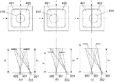
図2に示す撮像素子の1つの画素200Gを、撮像素子の受光面側(+z側)から見た平面図を図3(a)に示し、図3(a)のa−a断面を−y側から見た断面図を図3(b)に示す。 A plan view of one pixel 200G of the image sensor shown in FIG. 2 as viewed from the light receiving surface side (+ z side) of the image sensor is shown in FIG. 3A, and the aa cross section of FIG. A cross-sectional view seen from the side is shown in FIG.
図3に示すように、本実施例の画素200Gでは、各画素の受光面側に入射光を集光するためのマイクロレンズ305が形成され、x方向にNH分割(2分割)、y方向にNV分割(1分割)された光電変換部301と光電変換部302が形成される。光電変換部301と光電変換部302が、それぞれ、第1の焦点検出画素201と第2の焦点検出画素202に対応する。
As shown in FIG. 3, in the pixel 200G of the present embodiment, a
光電変換部301と光電変換部302は、p型層とn型層の間にイントリンシック層を挟んだpin構造フォトダイオードとしても良いし、必要に応じて、イントリンシック層を省略し、pn接合フォトダイオードとしても良い。
The
各画素には、マイクロレンズ305と、光電変換部301および光電変換部302との間に、カラーフィルター306が形成される。また、必要に応じて、副画素毎にカラーフィルターの分光透過率を変えても良いし、カラーフィルターを省略しても良い。
In each pixel, a
図3に示した画素200Gに入射した光は、マイクロレンズ305により集光され、カラーフィルター306で分光されたのち、光電変換部301と光電変換部302で受光される。光電変換部301と光電変換部302では、光電変換により、受光量に応じて電子とホールが対生成し、空乏層で分離された後、負電荷の電子はn型層(不図示)に蓄積される。一方、ホールは定電圧源(不図示)に接続されたp型層を通じて撮像素子外部へ排出される。光電変換部301と光電変換部302のn型層(不図示)に蓄積された電子は、転送ゲートを介して、静電容量部(FD)(不図示)に転送され、電圧信号に変換されて画素信号として出力される。
The light incident on the
図3に示した本実施例の画素構造と瞳分割との対応関係を図4に示す。図3(a)に示した本第1の実施例の画素構造のa−a断面を+y側から見た断面図と結像光学系の射出瞳面を示す。図4では、射出瞳面の座標軸と対応を取るために、断面図のx軸とy軸を図3に対して反転させている。なお、図4において、図3と同様の部分は同じ符号を付して示す。 FIG. 4 shows the correspondence between the pixel structure of this embodiment shown in FIG. 3 and pupil division. FIG. 3A is a cross-sectional view of the pixel structure of the first embodiment shown in FIG. 3A as viewed from the + y side and an exit pupil plane of the imaging optical system. In FIG. 4, in order to correspond to the coordinate axis of the exit pupil plane, the x-axis and y-axis of the cross-sectional view are inverted with respect to FIG. In FIG. 4, the same parts as those in FIG. 3 are denoted by the same reference numerals.
図4に示すように、第1の焦点検出画素201の第1の瞳部分領域401は、重心が−x方向に偏心している光電変換部301の受光面と、マイクロレンズによって、概ね、共役関係になっており、第1の焦点検出画素201で受光可能な瞳領域を表している。第1の焦点検出画素201の第1の瞳部分領域401は、瞳面上で+X側に重心が偏心している。図4で、第2の焦点検出画素202の第2の瞳部分領域402は、重心が+x方向に偏心している光電変換部302の受光面と、マイクロレンズによって、概ね、共役関係になっており、第2の焦点検出画素202で受光可能な瞳領域を表している。第2の焦点検出画素202の第2の瞳部分領域402は、瞳面上で−X側に重心が偏心している。また、図4で、瞳領域400は、光電変換部301と光電変換部302(第1の焦点検出画素201と第2の焦点検出画素202)とを合わせた際の画素200G全体で受光可能な瞳領域である。
As shown in FIG. 4, the first pupil
本実施例の撮像素子とマイクロレンズ(瞳分割手段)による瞳分割との対応関係の概略を図5に示す。射出瞳410の第1の瞳部分領域401と第2の瞳部分領域402の異なる瞳部分領域を通過した光束は、撮像素子の各画素に、それぞれ、異なる角度で入射し、2×1分割された第1の焦点検出画素201と第2の焦点検出画素202で受光される。なお、本実施例では、瞳領域が水平方向に2つに瞳分割されている例を示しているが、必要に応じて、垂直方向に瞳分割を行っても良い。
FIG. 5 shows an outline of the correspondence between the image pickup element of the present embodiment and pupil division by a microlens (pupil dividing means). Light beams that have passed through different pupil partial regions of the first pupil
上述のように、本実施例で用いる撮像素子は、結像光学系の第1の瞳部分領域を通過する光束を受光する第1の焦点検出画素と、第1瞳部分領域と異なる結像光学系の第2の瞳部分領域を通過する光束を受光する第2の焦点検出画素を有する。また、結像光学系の第1の瞳部分領域と第2の瞳部分領域を合わせた瞳領域を通過した光束を受光する撮像画素の配列も有する。本実施例の撮像素子では、それぞれの撮像画素が第1の焦点検出画素と第2の焦点検出画素から構成されている。しかし、必要に応じて、撮像画素と第1の焦点検出画素、第2の焦点検出画素を個別の画素構成とし、撮像画素配列の一部に、第1の焦点検出画素と第2の焦点検出画素を部分的に配置する構成としても良い。 As described above, the imaging device used in the present embodiment includes the first focus detection pixel that receives the light beam passing through the first pupil partial region of the imaging optical system, and the imaging optics different from the first pupil partial region. A second focus detection pixel for receiving the light beam passing through the second pupil partial region of the system; In addition, it has an array of imaging pixels that receive a light beam that has passed through a pupil region that is a combination of the first pupil partial region and the second pupil partial region of the imaging optical system. In the imaging device of the present embodiment, each imaging pixel is composed of a first focus detection pixel and a second focus detection pixel. However, if necessary, the imaging pixel, the first focus detection pixel, and the second focus detection pixel are configured as separate pixels, and the first focus detection pixel and the second focus detection are included in a part of the imaging pixel array. A configuration in which pixels are partially arranged may be employed.
本実施例では、撮像素子の各画素の第1の焦点検出画素201の受光信号を集めて第1焦点検出信号を生成し、各画素の第2の焦点検出画素202の受光信号を集めて第2の焦点検出信号を生成(信号生成手段)して焦点検出を行う。また、撮像素子の画素毎に、第1の焦点検出画素201と第2の焦点検出画素202の信号を加算することで、有効画素数Nの解像度の撮像信号(撮像画像)を生成する。
In this embodiment, the first
[デフォーカス量と像ずれ量の関係]
次に、本実施例で用いる撮像素子により取得される第1の焦点検出信号と第2の焦点検出信号の像ずれ量とデフォーカス量との関係について説明する。
[Relationship between defocus amount and image shift amount]
Next, the relationship between the image shift amount and the defocus amount of the first focus detection signal and the second focus detection signal acquired by the image sensor used in this embodiment will be described.
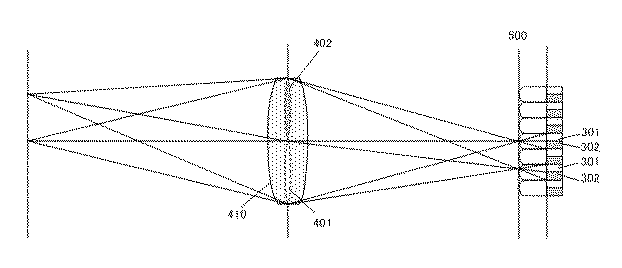
図6に、第1の焦点検出信号と第2の焦点検出信号のデフォーカス量と第1の焦点検出信号と第2の焦点検出信号間の像ずれ量の関係を示す。撮像面500に本実施例の撮像素子(不図示)が配置され、図4、図5と同様に、結像光学系の射出瞳が、第1の瞳部分領域401と第2瞳部分領域402に2分割される。なお、図6において、図3乃至及び5と同様な部分は同じ符号を付して示す。
FIG. 6 shows the relationship between the defocus amounts of the first focus detection signal and the second focus detection signal, and the image shift amount between the first focus detection signal and the second focus detection signal. The imaging element (not shown) of the present embodiment is arranged on the
デフォーカス量dは、被写体の結像位置から撮像面500までの距離を大きさ|d|としたとき、被写体の結像位置が撮像面より被写体側にある前ピン状態を負(d<0)、撮像面500より被写体の反対側にある後ピン状態を正(d>0)として定義される。被写体の結像位置が撮像面500(合焦位置)にある合焦状態はd=0である。図6で、被写体601は合焦状態(d=0)の例を示しており、被写体602は前ピン状態(d<0)の例を示している。前ピン状態(d<0)と後ピン状態(d>0)を合わせて、デフォーカス状態(|d|>0)とする。
The defocus amount d is negative (d <0) when the distance from the imaging position of the subject to the
前ピン状態(d<0)では、被写体602からの光束のうち、第1の瞳部分領域401を通過した被写体光は、一度、集光した後、光束の重心位置G1を中心として幅Γ1に広がり、撮像面500でボケた像となる。第2の瞳部分領域402を通過した被写体光についても同様であり、重心位置G2を中心として幅Γ2に広がったボケた像を形成する。ボケた像は、撮像素子に配列された各画素を構成する第1の焦点検出画素201(第2の焦点検出画素202)により受光され、第1の焦点検出信号(第2の焦点検出信号)が生成される。よって、第1の焦点検出信号(第2の焦点検出信号)は、撮像面500上の重心位置G1(G2)に、被写体602が幅Γ1(Γ2)にボケた被写体像として記録される。被写体像のボケ幅Γ1(Γ2)は、デフォーカス量dの大きさ|d|が増加するのに伴い、概ね、比例して増加していく。同様に、第1の焦点検出信号と第2の焦点検出信号間の被写体像の像ずれ量p(=光束の重心位置の差G1−G2)の大きさ|p|も、デフォーカス量dの大きさ|d|が増加するのに伴い、概ね、比例して増加していく。後ピン状態(d>0)でも、第1の焦点検出信号と第2の焦点検出信号間の被写体像の像ずれ方向が前ピン状態と反対となるが、同様である。
In the front pin state (d <0), the subject light that has passed through the first pupil
したがって、第1の焦点検出信号と第2の焦点検出信号、もしくは、第1の焦点検出信号と第2の焦点検出信号を加算した撮像信号のデフォーカス量の大きさが増加するのに伴い、第1の焦点検出信号と第2の焦点検出信号間の像ずれ量の大きさが増加する。 Therefore, as the magnitude of the defocus amount of the first focus detection signal and the second focus detection signal or the imaging signal obtained by adding the first focus detection signal and the second focus detection signal increases, The amount of image shift between the first focus detection signal and the second focus detection signal increases.
[焦点検出]
本実施例では、上述した第1の焦点検出信号と第2の焦点検出信号のデフォーカス量と像ずれ量の関連性を用いて、位相差方式の第1の焦点検出と、リフォーカス原理に基づいた方式(以後、リフォーカス方式と呼ぶ)の第2の焦点検出を行う。被写体の焦点調節状態が大デフォーカス状態から小デフォーカス状態までは第1の焦点検出を行い、小デフォーカス状態から最良合焦位置近傍までは第2の焦点検出を行う。被写体の焦点調節状態の判定は、本実施例では、所定値と検出されたデフォーカス量との比較で判断する。
[Focus detection]
In this embodiment, the first focus detection of the phase difference method and the refocus principle are used by using the relationship between the defocus amount and the image shift amount of the first focus detection signal and the second focus detection signal described above. The second focus detection of the based method (hereinafter referred to as the refocus method) is performed. The first focus detection is performed from the large defocus state to the small defocus state, and the second focus detection is performed from the small defocus state to the vicinity of the best focus position. In this embodiment, the focus adjustment state of the subject is determined by comparing the predetermined value with the detected defocus amount.
[位相差方式の第1の焦点検出]
まず、本の実施例における位相差方式の第1の焦点検出について説明する。
[First focus detection of phase difference method]
First, the first focus detection of the phase difference method in the present embodiment will be described.
位相差方式の第1の焦点検出では、第1の焦点検出信号と第2の焦点検出信号を相対的にシフトさせて信号の一致度を表す相関量(第1の評価値)を計算し、相関(信号の一致度)が良くなるシフト量から像ずれ量を検出する。撮像信号のデフォーカス量の大きさが増加するのに伴い、第1の焦点検出信号と第2の焦点検出信号間の像ずれ量の大きさが増加する関連性から、像ずれ量を第1の検出デフォーカス量に変換して焦点検出を行う。 In the first focus detection of the phase difference method, the first focus detection signal and the second focus detection signal are relatively shifted to calculate a correlation amount (first evaluation value) representing the degree of coincidence of the signals, The image shift amount is detected from the shift amount that improves the correlation (signal coincidence). As the magnitude of the defocus amount of the imaging signal increases, the image shift amount is set to the first because of the relationship that the image shift amount increases between the first focus detection signal and the second focus detection signal. The focus is detected by converting to the detected defocus amount.
図7に、本第1の実施例の第1の焦点検出動作のフローチャートを示す。なお、図7の動作は、撮像素子107、画像処理部125と、それらを制御するCPU121によって実行される。
FIG. 7 shows a flowchart of the first focus detection operation of the first embodiment. 7 is performed by the
ステップS710で、まずCPU121は、撮像素子の有効画素領域の中から焦点調節を行う焦点検出領域を設定する。次いで、CPU121は撮像素子107を制御し、焦点検出領域の第1の焦点検出画素の受光信号から第1の焦点検出信号を、また焦点検出領域の第2の焦点検出画素の受光信号から第2の焦点検出信号を取得する。
In step S710, the
ステップS720で、画像処理部125は、第1の焦点検出信号と第2の焦点検出信号に、それぞれ、信号データ量を抑制するために列方向に3画素加算処理を行い、さらに、RGB信号を輝度Y信号にするためにベイヤー(RGB)加算処理を行う。これら2つの加算処理を合わせて第1の画素加算処理とする。
In step S720, the
ステップS730で画像処理部125はさらに、第1の焦点検出信号と第2の焦点検出信号に、それぞれ、シェーディング補正処理(光学補正処理)を行う。位相差方式の第1の焦点検出では、第1の焦点検出信号と第2の焦点検出信号の相関(信号の一致度)を基に、第1の検出デフォーカス量の検出を行う。瞳ずれによるシェーディングが生じると第1の焦点検出信号と第2の焦点検出信号の相関(信号の一致度)が低下する場合がある。よって、位相差方式の第1の焦点検出では、第1の焦点検出信号と第2の焦点検出信号の相関(信号の一致度)を改善し、焦点検出性能を良好とするために、シェーディング補正処理(光学補正処理)を行うことが望ましい。
In step S730, the
ここで、第1の焦点検出信号と第2の焦点検出信号の瞳ずれによるシェーディングについて説明する。
図8に、撮像素子の周辺像高における第1の焦点検出画素201の第1の瞳部分領域401、第2の焦点検出画素202の第2の瞳部分領域402、および結像光学系の射出瞳410の関係を示す。尚、図4と同じ部分は同じ符号を付して示す。
Here, the shading by the pupil shift of the first focus detection signal and the second focus detection signal will be described.
FIG. 8 shows the first pupil
図8(a)は、結像光学系の射出瞳距離Dlと撮像素子の設定瞳距離Dsが同じ場合である。この場合は、第1の瞳部分領域401と第2の瞳部分領域402により、結像光学系の射出瞳410が、概ね、均等に瞳分割される。
FIG. 8A shows a case where the exit pupil distance Dl of the imaging optical system and the set pupil distance Ds of the image sensor are the same. In this case, the
これに対して、図8(b)に示した結像光学系の射出瞳距離Dlが撮像素子の設定瞳距離Dsより短い場合、撮像素子の周辺像高では、結像光学系の射出瞳と撮像素子の入射瞳の瞳ずれを生じ、結像光学系の射出瞳410が、不均一に瞳分割されてしまう。同様に、図8(c)に示した結像光学系の射出瞳距離Dlが撮像素子の設定瞳距離Dsより長い場合も、撮像素子の周辺像高で結像光学系の射出瞳と撮像素子の入射瞳の瞳ずれを生じ、結像光学系の射出瞳410が、不均一に瞳分割されてしまう。周辺像高で瞳分割が不均一になるのに伴い、第1の焦点検出信号と第2の焦点検出信号の強度も不均一になり、第1の焦点検出信号と第2の焦点検出信号のいずれか一方の強度が大きくなり、他方の強度が小さくなるシェーディングが生じる。
On the other hand, when the exit pupil distance D1 of the imaging optical system shown in FIG. 8B is shorter than the set pupil distance Ds of the image sensor, the peripheral pupil height of the image sensor is equal to the exit pupil of the imaging optical system. A pupil shift of the entrance pupil of the image sensor occurs, and the
図7のステップS730で画像処理部125はシェーディング補正処理(光学補正処理)を行う。まず、焦点検出領域の像高と、撮像レンズ(結像光学系)のF値、射出瞳距離に応じて、第1の焦点検出信号の第1のシェーディング補正係数と、第2の焦点検出信号の第2のシェーディング補正係数を、それぞれ生成する。次いで、第1のシェーディング補正係数を第1の焦点検出信号に乗算し、第2のシェーディング補正係数を第2の焦点検出信号に乗算して、第1の焦点検出信号と第2の焦点検出信号のシェーディング補正処理(光学補正処理)を終了する。
In step S730 in FIG. 7, the
図7のステップS740では、第1の焦点検出信号と第2の焦点検出信号に、第1のフィルター処理を行う。本実施例の第1のフィルター処理の通過帯域例を、図9に実線で示す。本実施例では、位相差方式の第1の焦点検出により、大デフォーカス状態での焦点検出を行うため、第1のフィルター処理の通過帯域は低周波帯域を含むように構成する。必要に応じて、大デフォーカス状態から小デフォーカス状態まで焦点調節を行う際に、デフォーカス状態に応じて、第1の焦点検出時の第1のフィルター処理の通過帯域を、図9に1点鎖線で示すように、より高周波帯域に調整しても良い。 In step S740 of FIG. 7, the first filter processing is performed on the first focus detection signal and the second focus detection signal. An example of the pass band of the first filter processing of the present embodiment is shown by a solid line in FIG. In the present embodiment, since the focus detection in the large defocus state is performed by the first focus detection of the phase difference method, the pass band of the first filter processing is configured to include the low frequency band. When the focus adjustment is performed from the large defocus state to the small defocus state as necessary, the pass band of the first filter processing at the time of the first focus detection according to the defocus state is represented by 1 in FIG. You may adjust to a higher frequency band as shown with a dashed-dotted line.
次に、図7のステップS750では、第1のフィルター処理後の第1の焦点検出信号と第2の焦点検出信号を相対的に瞳分割方向にシフトさせる第1のシフト処理を行い、信号の一致度を表す相関量(第1の評価値)を算出する。 Next, in step S750 of FIG. 7, a first shift process for relatively shifting the first focus detection signal and the second focus detection signal after the first filter process in the pupil division direction is performed. A correlation amount (first evaluation value) representing the degree of coincidence is calculated.
第1のフィルター処理後のk番目の第1の焦点検出信号をA(k)、第2の焦点検出信号をB(k)、焦点検出領域に対応する番号kの範囲をWとする。第1のシフト処理によるシフト量をs1、シフト量s1のシフト範囲をΓ1として、相関量(第1の評価値)CORは、式(1)により算出される。
シフト量s1の第1のシフト処理により、k番目の第1の焦点検出信号A(k)とk−s1番目の第2の焦点検出信号B(k−s1)を対応させ減算し、シフト減算信号を生成する。生成されたシフト減算信号の絶対値を計算し、焦点検出領域に対応する範囲W内で番号kの和を取り、相関量(第1の評価値)COR(s1)を算出する。必要に応じて、各行毎に算出された相関量(第1の評価値)を、各シフト量毎に、複数行に渡って加算しても良い。 By the first shift process of the shift amount s1, the k-th first focus detection signal A (k) and the k-s1st second focus detection signal B (k-s1) are made to correspond to each other and subtracted. Generate a signal. The absolute value of the generated shift subtraction signal is calculated, the number k is summed within the range W corresponding to the focus detection area, and the correlation amount (first evaluation value) COR (s1) is calculated. If necessary, the correlation amount (first evaluation value) calculated for each row may be added over a plurality of rows for each shift amount.
ステップS760では、相関量(第1の評価値)から、サブピクセル演算により、相関量が最小値となる実数値のシフト量を算出して像ずれ量p1とする。像ずれ量p1に、焦点検出領域の像高と、撮像レンズ(結像光学系)のF値、射出瞳距離に応じた第1の変換係数K1をかけて、第1の検出デフォーカス量(Def1)を検出する。 In step S760, from the correlation amount (first evaluation value), a real-valued shift amount at which the correlation amount is the minimum value is calculated by subpixel calculation, and is set as the image shift amount p1. The image shift amount p1 is multiplied by the image height of the focus detection area, the F value of the imaging lens (imaging optical system), and the first conversion coefficient K1 corresponding to the exit pupil distance to obtain a first detection defocus amount ( Def1) is detected.
上述したように、本実施例では、位相差方式の第1の焦点検出手段により、第1の焦点検出信号と第2の焦点検出信号に、第1のフィルター処理と第1のシフト処理を行って相関量を算出し、相関量から第1の検出デフォーカス量を検出する。 As described above, in this embodiment, the first filter processing and the first shift processing are performed on the first focus detection signal and the second focus detection signal by the first focus detection means of the phase difference method. The correlation amount is calculated, and the first detection defocus amount is detected from the correlation amount.
本実施例の撮像素子では、焦点検出画素(第1の焦点検出画素、第2の焦点検出画素)が受光する光束と、撮像画素が受光する光束が異なる。このため、結像光学系の各収差(球面収差、非点収差、コマ収差など)の焦点検出画素への影響と撮像信号への影響が異なる。結像光学系の絞り値が小さい(明るい)と差異がより大きくなる。そのため、結像光学系の絞り値が小さい(明るい)時に、位相差方式の第1の焦点検出により算出される検出合焦位置と撮像信号の最良合焦位置との間に差が生じる場合がある。特に、結像光学系の絞り値が所定絞り値以下の場合に、位相差方式の第1の焦点検出の焦点検出精度が低下する場合がある。なお、ここで、検出合焦位置とは、第1の検出デフォーカス量が0となる位置であり、また、撮像信号の最良合焦位置は撮像信号のMTF(Modulation Transfer Function)ピーク位置である。 In the image sensor of the present embodiment, the light flux received by the focus detection pixels (first focus detection pixel and second focus detection pixel) is different from the light flux received by the imaging pixels. For this reason, the influence of each aberration (spherical aberration, astigmatism, coma aberration, etc.) of the imaging optical system on the focus detection pixel is different from the influence on the imaging signal. The difference becomes larger when the aperture value of the imaging optical system is small (bright). For this reason, when the aperture value of the imaging optical system is small (bright), there may be a difference between the detection focus position calculated by the first focus detection of the phase difference method and the best focus position of the imaging signal. is there. In particular, when the aperture value of the imaging optical system is equal to or smaller than a predetermined aperture value, the focus detection accuracy of the first focus detection of the phase difference method may be lowered. Here, the detection focus position is a position where the first detection defocus amount is 0, and the best focus position of the imaging signal is an MTF (Modulation Transfer Function) peak position of the imaging signal. .
図10に、本実施例の撮像素子の周辺像高での撮像信号の最良合焦位置における第1の焦点検出信号(破線)と第2の焦点検出信号(実線)の例を示す。撮像信号の最良合焦位置であるが、結像光学系の各収差の影響により、第1の焦点検出信号と第2の焦点検出信号の信号形状が異なる例である。図11に、シェーディング補正処理および第1のフィルター処理後の第1の焦点検出信号(破線)と第2の焦点検出信号(実線)を示す。撮像信号の最良合焦位置であるが、第1の焦点検出信号と第2の焦点検出信号間の像すれ量p1が0ではない。よって、位相差方式の第1の焦点検出により算出される検出合焦位置と撮像信号の最良合焦位置との間に差が生じる。 FIG. 10 shows an example of the first focus detection signal (broken line) and the second focus detection signal (solid line) at the best focus position of the image pickup signal at the peripheral image height of the image sensor of the present embodiment. Although it is the best focus position of the imaging signal, the signal shapes of the first focus detection signal and the second focus detection signal are different due to the influence of each aberration of the imaging optical system. FIG. 11 shows the first focus detection signal (broken line) and the second focus detection signal (solid line) after the shading correction process and the first filter process. Although it is the best in-focus position of the imaging signal, the image blur amount p1 between the first focus detection signal and the second focus detection signal is not zero. Therefore, a difference is generated between the detection focus position calculated by the first focus detection of the phase difference method and the best focus position of the imaging signal.
図12に、本実施例における位相差方式の第1の焦点検出による第1の検出デフォーカス量(破線)の例を示す。横軸は、設定デフォーカス量であり、縦軸は検出デフォーカス量である。図10に示した第1の焦点検出信号と第2の焦点検出信号は、図12の設定デフォーカス量0[mm]における第1の焦点検出信号と第2の焦点検出信号である。設定デフォーカス量0の最良合焦位置において、第1の焦点検出による第1の検出デフォーカス量が後ピン側に約50μmオフセットしており、最良合焦位置と第1の焦点検出により算出される検出合焦位置との間に約50μmの差異が生じていることがわかる。 FIG. 12 shows an example of the first detected defocus amount (broken line) by the first focus detection of the phase difference method in the present embodiment. The horizontal axis is the set defocus amount, and the vertical axis is the detected defocus amount. The first focus detection signal and the second focus detection signal shown in FIG. 10 are the first focus detection signal and the second focus detection signal at the set defocus amount 0 [mm] in FIG. At the best focus position with a set defocus amount of 0, the first detection defocus amount by the first focus detection is offset by about 50 μm to the rear pin side, and is calculated by the best focus position and the first focus detection. It can be seen that there is a difference of about 50 μm from the detected focus position.
そこで、本実施例では、焦点検出信号から算出される検出合焦位置と撮像信号の最良合焦位置との差を抑制するため、位相差方式の第1の焦点検出に加えて、結像光学系の最良合焦位置近傍で高精度な焦点検出が可能なリフォーカス方式の第2の焦点検出を行う。これにより、高精度な焦点検出が可能となる。 Therefore, in this embodiment, in order to suppress the difference between the detection focus position calculated from the focus detection signal and the best focus position of the imaging signal, in addition to the first focus detection of the phase difference method, the imaging optical The second focus detection of the refocus method capable of detecting the focus with high accuracy near the best focus position of the system is performed. Thereby, highly accurate focus detection is possible.
[リフォーカス方式の第2の焦点検出]
次に、本実施例におけるリフォーカス方式の第2の焦点検出について説明する。
[Second focus detection by refocusing method]
Next, the second focus detection of the refocus method in the present embodiment will be described.
本実施例のリフォーカス方式の第2の焦点検出では、第1の焦点検出信号と第2の焦点検出信号を相対的にシフトして加算し、シフト加算信号(リフォーカス信号)を生成する。次いで、生成されたシフト加算信号(リフォーカス信号)のコントラスト評価値を算出し、コントラスト評価値から撮像信号のMTFピーク位置を推定し、第2の検出デフォーカス量を検出する。 In the second focus detection of the refocus method of the present embodiment, the first focus detection signal and the second focus detection signal are relatively shifted and added to generate a shift addition signal (refocus signal). Next, a contrast evaluation value of the generated shift addition signal (refocus signal) is calculated, an MTF peak position of the imaging signal is estimated from the contrast evaluation value, and a second detection defocus amount is detected.
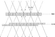
図13は、本実施例の撮像素子により取得された第1の焦点検出信号と第2の焦点検出信号による1次元方向(行方向、水平方向)のリフォーカス処理を明図するための図である。同図において、図5、図6と同様の部分は同じ符号を付して示す。図13では、iを整数として、撮像面500に配置された撮像素子の行方向i番目の画素の第1の焦点検出信号をAi、第2の焦点検出信号をBiで模式的に表している。第1の焦点検出信号Aiは、(図5の瞳部分領域401に対応した)主光線角度θaでi番目の画素に入射した光束の受光信号である。第2の焦点検出信号Biは、(図5の瞳部分領域402に対応した)主光線角度θbでi番目の画素に入射した光束の受光信号である。
FIG. 13 is a diagram for clarifying the refocus processing in the one-dimensional direction (row direction, horizontal direction) by the first focus detection signal and the second focus detection signal acquired by the image sensor of the present embodiment. is there. In the figure, the same parts as those in FIGS. 5 and 6 are denoted by the same reference numerals. In FIG. 13, i is an integer, and the first focus detection signal of the i-th pixel in the row direction of the image sensor arranged on the
第1の焦点検出信号Aiと第2の焦点検出信号Biは、光強度分布情報だけでなく、入射角度情報も有している。よって、第1の焦点検出信号Aiを角度θaに沿って仮想結像面1310まで平行移動させ、第2の焦点検出信号Biを角度θbに沿って仮想結像位置1310まで平行移動させ、加算することで、仮想結像面1310でのリフォーカス信号を生成できる。第1の焦点検出信号Aiを角度θaに沿って仮想結像面1310まで平行移動させることは、行方向に+0.5画素シフトに対応し、第2の焦点検出信号Biを角度θbに沿って仮想結像面1310まで平行移動させることは、行方向に−0.5画素シフトに対応する。したがって、第1の焦点検出信号Aiと第2の焦点検出信号Biを相対的に+1画素シフトさせ、AiとBi+1を対応させて加算することで、仮想結像面1310でのリフォーカス信号を生成できる。同様に、第1の焦点検出信号Aiと第2の焦点検出信号Biを画素整数個分シフトさせて加算することで、整数シフト量に応じた各仮想結像面でのシフト加算信号(リフォーカス信号)を生成できる。
The first focus detection signal Ai and the second focus detection signal Bi have not only light intensity distribution information but also incident angle information. Therefore, the first focus detection signal Ai is translated along the angle θa to the
生成されたシフト加算信号(リフォーカス信号)のコントラスト評価値を算出し、算出されたコントラスト評価値から撮像信号のMTFピーク位置を推定することで、リフォーカス方式の第2の焦点検出を行う。 The contrast evaluation value of the generated shift addition signal (refocus signal) is calculated, and the MTF peak position of the imaging signal is estimated from the calculated contrast evaluation value, thereby performing the second focus detection of the refocus method.
図14に、本第1の実施例の第2の焦点検出動作のフローチャートを示す。なお、図14の動作も、撮像素子107、画像処理部125およびそれらを制御するCPU121によって実行される。
FIG. 14 shows a flowchart of the second focus detection operation of the first embodiment. 14 is also executed by the
ステップS1410で、CPU121は、まず撮像素子の有効画素領域の中から焦点調節を行う焦点検出領域を設定する。次いで、撮像素子107の駆動を制御して、焦点検出信号生成手段により、焦点検出領域の第1の焦点検出画素の受光信号から第1の焦点検出信号を、また焦点検出領域の第2の焦点検出画素の受光信号から第2の焦点検出信号を取得する。
In step S1410, the
ステップS1420で、第1の焦点検出信号と第2の焦点検出信号に、それぞれ、信号データ量を抑制するために列方向に3画素加算処理を行い、さらに、RGB信号を輝度Y信号にするためにベイヤー(RGB)加算処理を行う。これら2つの加算処理を合わせて第2の画素加算処理とする。必要に応じて、3画素加算処理とベイヤー(RGB)加算処理のいずれか、または、これら両方の加算処理を省略しても良い。 In step S1420, the first focus detection signal and the second focus detection signal are each subjected to 3-pixel addition processing in the column direction in order to suppress the amount of signal data, and further, the RGB signal is converted into a luminance Y signal. The Bayer (RGB) addition process is performed on These two addition processes are combined into a second pixel addition process. If necessary, one or both of the three-pixel addition processing and the Bayer (RGB) addition processing may be omitted.
ステップS1430では、第1の焦点検出信号と第2の焦点検出信号に、第2フィルター処理を行う。本第1の実施例の第2のフィルター処理の通過帯域例を、図9の破線および点線で示す。本実施例では、リフォーカス方式の第2の焦点検出により、小デフォーカス状態から最良合焦位置近傍まで焦点検出を行う。したがって、第2フィルター処理の通過帯域は、第1フィルター処理の通過帯域よりも、高周波帯域を含むように構成する。 In step S1430, second filter processing is performed on the first focus detection signal and the second focus detection signal. An example of a pass band of the second filter processing of the first embodiment is indicated by a broken line and a dotted line in FIG. In this embodiment, focus detection is performed from the small defocus state to the vicinity of the best focus position by the second focus detection of the refocus method. Therefore, the pass band of the second filter process is configured to include a higher frequency band than the pass band of the first filter process.
必要に応じて、第2フィルター処理に被写体信号のエッジ抽出を行うラプラシアン型(2階微分型)[1、−2、1]フィルターを用いて、図9の点線で示すように第2のフィルター処理の通過帯域をより高周波帯域に構成しても良い。被写体の高周波成分を抽出して第2の焦点検出を行うことにより、焦点検出精度をより向上することができる。 If necessary, a second filter processing is performed using a Laplacian type (second-order differential type) [1, -2, 1] filter that performs edge extraction of the subject signal, as shown by a dotted line in FIG. You may comprise the pass band of a process in a higher frequency band. By extracting the high frequency component of the subject and performing the second focus detection, the focus detection accuracy can be further improved.
ステップS1440では、第2フィルター処理後の第1の焦点検出信号と第2の焦点検出信号を相対的に瞳分割方向にシフトさせる第2のシフト処理を行い、加算してシフト加算信号(リフォーカス信号)を生成する。 In step S1440, a second shift process is performed in which the first focus detection signal and the second focus detection signal after the second filter process are relatively shifted in the pupil division direction, and are added to obtain a shift addition signal (refocus). Signal).
ステップS1440では、さらに、生成されたシフト加算信号からコントラスト評価値(第2の評価値)を算出する。 In step S1440, a contrast evaluation value (second evaluation value) is further calculated from the generated shift addition signal.
第1のフィルター処理後のk番目の第1の焦点検出信号をA(k)、第2の焦点検出信号をB(k)、焦点検出領域に対応する番号kの範囲をWとする。第2シフト処理によるシフト量をs2、シフト量s2のシフト範囲をΓ2として、コントラスト評価値(第2の評価値)RFCONは、式(2)により算出される。
![]()
![]()
シフト量s2の第2のシフト処理により、k番目の第1の焦点検出信号A(k)とk−s2番目の第2の焦点検出信号B(k−s2)を対応させて加算し、シフト加算信号を生成する。シフト加算信号の絶対値を計算し、焦点検出領域Wの範囲での最大値を取り、コントラスト評価値(第2の評価値)RFCON(s2)を算出する。必要に応じて、各行毎に算出されたコントラスト評価値(第2の評価値)を、各シフト量毎に、複数行に渡って加算しても良い。 By the second shift process of the shift amount s2, the k-th first focus detection signal A (k) and the k-s2nd second focus detection signal B (k-s2) are added correspondingly and shifted. Generate a sum signal. The absolute value of the shift addition signal is calculated, the maximum value in the range of the focus detection area W is taken, and the contrast evaluation value (second evaluation value) RFCON (s2) is calculated. If necessary, the contrast evaluation value (second evaluation value) calculated for each row may be added over a plurality of rows for each shift amount.
ステップS1450では、コントラスト評価値(第2の評価値)から、サブピクセル演算により、コントラスト評価値が最大値となる実数値のシフト量を算出してピークシフト量p2とする。ピークシフト量p2に、焦点検出領域の像高と、撮像レンズ(結像光学系)のF値、射出瞳距離に応じた第2の変換係数K2をかけて、第2の検出デフォーカス量(Def2)を検出する。なお、必要に応じて、第1の変換係数K1と第2の変換係数K2を同一の値としても良い。 In step S1450, from the contrast evaluation value (second evaluation value), a real-value shift amount at which the contrast evaluation value becomes the maximum value is calculated by subpixel calculation, and is set as the peak shift amount p2. Multiplying the peak shift amount p2 by the image height of the focus detection area, the F value of the imaging lens (imaging optical system), and the second conversion coefficient K2 corresponding to the exit pupil distance, the second detection defocus amount ( Def2) is detected. If necessary, the first conversion coefficient K1 and the second conversion coefficient K2 may be the same value.
本発明では、リフォーカス方式の第2の焦点検出手段により、第1の焦点検出信号と前記第2の焦点検出信号に、第2のフィルター処理と第2のシフト処理を行い、その後加算してシフト加算信号を生成する。次いで、シフト加算信号からコントラスト評価値を算出し、コントラスト評価値から第2の検出デフォーカス量を検出する。 In the present invention, the second filter processing and the second shift processing are performed on the first focus detection signal and the second focus detection signal by the second focus detection means of the refocus method, and then added. A shift addition signal is generated. Next, a contrast evaluation value is calculated from the shift addition signal, and a second detected defocus amount is detected from the contrast evaluation value.
本実施例の撮像素子では、図4、図5に示したように、第1の焦点検出画素が受光する光束と第2の焦点検出画素が受光する光束を加算したものが、撮像画素が受光する光束となる。位相差方式の第1の焦点検出とは異なり、リフォーカス方式の第2の焦点検出では、第1の焦点検出信号と第2の焦点検出信号のシフト加算信号(リフォーカス信号)により焦点検出を行う。よって、第2の焦点検出で用いられるシフト加算信号に対応する光束と、撮像信号に対応する光束が、概ね、一致するため、結像光学系の各収差(球面収差、非点収差、コマ収差など)のシフト加算信号への影響と撮像信号への影響も、概ね、同じである。したがって、リフォーカス方式の第2の焦点検出により算出される検出合焦位置(第2の検出デフォーカス量が0となる位置)と撮像信号の最良合焦位置(MTFピーク位置)が、概ね、一致するため、位相差方式の第1の焦点検出より高精度に焦点検出できる。 In the imaging device of the present embodiment, as shown in FIGS. 4 and 5, the imaging pixel receives the light beam received by the first focus detection pixel and the light beam received by the second focus detection pixel. The luminous flux is Unlike the first focus detection of the phase difference method, in the second focus detection of the refocus method, focus detection is performed by a shift addition signal (refocus signal) of the first focus detection signal and the second focus detection signal. Do. Therefore, since the light beam corresponding to the shift addition signal used in the second focus detection and the light beam corresponding to the imaging signal are substantially the same, each aberration of the imaging optical system (spherical aberration, astigmatism, coma aberration) The influence on the shift addition signal and the influence on the imaging signal are generally the same. Therefore, the detection focus position (position where the second detection defocus amount is 0) calculated by the second focus detection of the refocus method and the best focus position (MTF peak position) of the imaging signal are approximately Since they match, focus detection can be performed with higher accuracy than the first focus detection using the phase difference method.
図10に例示した本実施例の撮像素子の周辺像高での撮像信号の最良合焦位置における第1の焦点検出信号(破線)と第2の焦点検出信号(実線)に、第2のフィルター処理を施した後の第1の焦点検出信号(破線)と第2の焦点検出信号(実線)を図15に示す。また、第2のフィルター処理後の第1の焦点検出信号(破線)と第2の焦点検出信号(実線)を、それぞれ、相対的に−2、−1、0、1、2シフトさせてシフト加算したシフト加算信号(リフォーカス信号)の例を図16に示す。シフト量の変化に伴い、シフト加算信号のピーク値が変化することがわかる。各シフト加算信号から算出されたコントラスト評価値(第2の評価値)の例を図17に示す。 A second filter is added to the first focus detection signal (broken line) and the second focus detection signal (solid line) at the best focus position of the image pickup signal at the peripheral image height of the image pickup device of the present embodiment illustrated in FIG. FIG. 15 shows the first focus detection signal (broken line) and the second focus detection signal (solid line) after processing. Further, the first focus detection signal (broken line) and the second focus detection signal (solid line) after the second filter processing are shifted by relatively shifting by -2, -1, 0, 1, 2, respectively. An example of the added shift addition signal (refocus signal) is shown in FIG. It can be seen that the peak value of the shift addition signal changes as the shift amount changes. An example of the contrast evaluation value (second evaluation value) calculated from each shift addition signal is shown in FIG.
図12に、本実施例におけるリフォーカス方式の第2の焦点検出による第2の検出デフォーカス量(実線)の例を示す。横軸は、設定デフォーカス量であり、縦軸は検出デフォーカス量である。図10に示した第1の焦点検出信号と第2の焦点検出信号は、図12の設定デフォーカス量0[mm]における第1の焦点検出信号と第2の焦点検出信号である。設定デフォーカス量0の最良合焦位置において、第2の焦点検出による第2検出デフォーカス量は、第1の焦点検出による第1の検出デフォーカス量よりも小さく抑制され、高精度に焦点検出できることがわかる。したがって、本実施例では、結像光学系の設定デフォーカス量0の最良合焦位置近傍において、リフォーカス方式の第2の焦点検出の方が、位相差方式の第1の焦点検出より、高精度に焦点検出できる。
FIG. 12 shows an example of the second detected defocus amount (solid line) by the second focus detection of the refocus method in the present embodiment. The horizontal axis is the set defocus amount, and the vertical axis is the detected defocus amount. The first focus detection signal and the second focus detection signal shown in FIG. 10 are the first focus detection signal and the second focus detection signal at the set defocus amount 0 [mm] in FIG. At the best in-focus position with the
[リフォーカス可能範囲]
一方、リフォーカス可能範囲には限界があるため、リフォーカス方式の第2の焦点検出が高精度で焦点検出できるデフォーカス量の範囲は限定される。
[Refocusable range]
On the other hand, since there is a limit to the refocusable range, the range of the defocus amount in which the refocus second focus detection can detect the focus with high accuracy is limited.
図18は、本実施例におけるリフォーカス可能範囲を明図するための図である。同図において、図5および6と同様の部分は、同じ符号を付して示す。図13に示すように、許容錯乱円をδとし、結像光学系の絞り値をFとすると、絞り値Fでの被写界深度は±Fδである。これに対して、NH×NV(2×1)分割されて狭くなった瞳部分領域401の水平方向の実効絞り値F01は、F01=NHFと暗くなる。第1の焦点検出信号毎の実効的な被写界深度は±NHFδとNH倍深くなり、合焦範囲がNH倍に広がる。実効的な被写界深度±NHFδの範囲内では、第1の焦点検出信号(第2の焦点検出信号)毎に合焦した被写体像が取得されている。瞳部分領域402の水平方向の実効絞り値F02についても同様であり、F02=NHFと暗くなり、第2の焦点検出信号毎の実効的な被写界深度は±NHFδとNH倍深くなる。この実効的な被写界深度の範囲内で、第2の焦点検出信号毎に合焦した被写体像が取得されている。よって、図13に示した主光線角度θa(またはθb)に沿って第1の焦点検出信号(または第2の焦点検出信号)を平行移動するリフォーカス処理により、撮影後に、合焦位置を再調整(リフォーカス)することができる。よって、撮影後に合焦位置を再調整(リフォーカス)できる撮像面からのデフォーカス量dは限定されており、デフォーカス量dのリフォーカス可能範囲は、概ね、式(3)の範囲である。
![]()
![]()
許容錯乱円δは、δ=2ΔX(画素周期ΔXのナイキスト周波数1/(2ΔX)の逆数)などで規定される。必要に応じて、第2画素加算処理後の第1の焦点検出信号(第2の焦点検出信号)の周期ΔXAF(=6ΔX:6画素加算の場合)のナイキスト周波数1/(2ΔXAF)の逆数を許容錯乱円δ=2ΔXAFとしても用いても良い。
The permissible circle of confusion δ is defined by δ = 2ΔX (the reciprocal of the
リフォーカス方式の第2の焦点検出が高精度で焦点検出できるデフォーカス量の範囲は、概ね、式(3)の範囲に限定され、第2の焦点検出により高精度に焦点検出可能なデフォーカス範囲は、位相差方式の第1の焦点検出可能なデフォーカス範囲以下の範囲である。図6に示したように、第1の焦点検出信号と第2の焦点検出信号との水平方向の相対的なシフト量とデフォーカス量は、概ね、比例する。したがって、本発明では、リフォーカス方式の第2の焦点検出の第2のシフト処理のシフト範囲が、位相差方式の第1の焦点検出の第1のシフト処理のシフト範囲以下となるように構成する。 The defocus amount range in which the refocus second focus detection can detect the focus with high accuracy is generally limited to the range of the expression (3), and the defocus that can detect the focus with high accuracy by the second focus detection. The range is a range equal to or less than the defocus range in which the first focus detection of the phase difference method can be performed. As shown in FIG. 6, the relative shift amount and the defocus amount in the horizontal direction between the first focus detection signal and the second focus detection signal are approximately proportional. Therefore, the present invention is configured such that the shift range of the second shift processing of the second focus detection of the refocus method is equal to or smaller than the shift range of the first shift processing of the first focus detection of the phase difference method. To do.
また、本実施例の焦点検出では、結像光学系の大デフォーカス状態から小デフォーカス状態まで焦点調節するために第1の焦点検出を行い、結像光学系の小デフォーカス状態から最良合焦位置近傍まで焦点調節するために第2の焦点検出を行う。したがって、第2の焦点検出の第2のフィルター処理の通過帯域が、第1の焦点検出の第1のフィルター処理の通過帯域より高周波帯域を含むことが望ましい。また、第2の焦点検出の第2の画素加算処理の画素加算数が、第1の焦点検出の第1の画素加算処理の画素加算数以下であることが望ましい。 In the focus detection of this embodiment, the first focus detection is performed to adjust the focus from the large defocus state to the small defocus state of the imaging optical system, and the best focus is detected from the small defocus state of the imaging optical system. Second focus detection is performed to adjust the focus to near the focal position. Therefore, it is desirable that the pass band of the second filtering process of the second focus detection includes a higher frequency band than the pass band of the first filtering process of the first focus detection. In addition, it is desirable that the pixel addition number in the second pixel addition process for the second focus detection is equal to or less than the pixel addition number in the first pixel addition process for the first focus detection.
上述したように、結像光学系の絞り値が所定の絞り値以下の場合に、位相差方式の第1の焦点検出の焦点検出精度が低下する場合がある。したがって、必要に応じて、結像光学系の絞り値が所定の絞り値以下の場合に、位相差方式の第1の焦点検出に加えて、リフォーカス方式の第2の焦点検出により第2の検出デフォーカス量を検出し、高精度な焦点検出を行うことが望ましい。 As described above, when the aperture value of the imaging optical system is equal to or smaller than the predetermined aperture value, the focus detection accuracy of the first focus detection of the phase difference method may be lowered. Therefore, if necessary, when the aperture value of the imaging optical system is equal to or smaller than the predetermined aperture value, the second focus detection by the refocusing method and the second focus detection by the refocusing method in addition to the first focus detection by the phase difference method. It is desirable to detect the detected defocus amount and perform highly accurate focus detection.
本実施例では、瞳領域が水平方向に2つに瞳分割されているため、撮像信号のコントラスト評価値から水平方向のMTFピーク位置を検出することができる。必要に応じて、撮像信号の水平方向のMTFピーク位置と撮像信号のMTFピーク位置(撮像信号の水平垂直方向のMTFピーク位置の平均)との差分を補正値として保持し、第2の検出デフォーカス量を補正しても良い。 In this embodiment, since the pupil region is divided into two pupils in the horizontal direction, the horizontal MTF peak position can be detected from the contrast evaluation value of the imaging signal. If necessary, the difference between the MTF peak position in the horizontal direction of the imaging signal and the MTF peak position of the imaging signal (the average of the MTF peak positions in the horizontal and vertical directions of the imaging signal) is held as a correction value, and the second detection data The focus amount may be corrected.
本実施例の焦点検出動作のフローチャートを図19に示す。なお、図19の動作も、撮像素子107、画像処理部125およびそれらを制御するCPU121によって実行される。
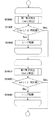
本第1の実施例では、結像光学系のデフォーカス量の絶対値が第1の所定値以下になるまで位相差方式の第1の焦点検出を行ってレンズ駆動し、結像光学系の大デフォーカス状態から小デフォーカス状態まで焦点調節を行う。その後、結像光学系のデフォーカス量の絶対値が第2の所定値(<第1の所定値)以下になるまでリフォーカス方式の第2の焦点検出を行ってレンズ駆動し、結像光学系の小デフォーカス状態から最良合焦位置近傍まで焦点調節を行う。
A flowchart of the focus detection operation of this embodiment is shown in FIG. 19 is also executed by the
In the first embodiment, the lens is driven by performing the first focus detection of the phase difference method until the absolute value of the defocus amount of the imaging optical system becomes equal to or less than the first predetermined value, and the lens of the imaging optical system is driven. Adjust the focus from the large defocus state to the small defocus state. Thereafter, the second focus detection of the refocus method is performed until the absolute value of the defocus amount of the imaging optical system becomes equal to or smaller than the second predetermined value (<first predetermined value), and the lens is driven to form the imaging optical. Focus adjustment is performed from the small defocus state of the system to the vicinity of the best focus position.
ステップS1900で、画像処理部125は、位相差方式による第1の焦点検出により第1の検出デフォーカス量(Def1)を検出する。この検出動作は、図7に示すフローチャートに従って画像処理部125が動作することで行われる。ステップS1901でCPU121は、第1のデフォーカス量(Def1)の大きさが第1の所定値より大きいかどうか判定する。検出された第1のデフォーカス量(Def1)の大きさ|Def1|が第1の所定値より大きい場合は、ステップS1902で、第1のデフォーカス量(Def1)に応じてレンズ駆動を行い、ステップS1900に戻る。検出された第1のデフォーカス量(Def1)の大きさ|Def1|が第1の所定値以下の場合は、ステップS1910に進む。
In step S1900, the
ステップS1910で、リフォーカス方式による第2の焦点検出により第2の検出デフォーカス量(Def2)を検出する。この検出動作は、図14に示すフローチャートに従って画像処理部125が動作することで行われる。ステップS1920でCPU121は、第2のデフォーカス量(Def2)の大きさが第2の所定値より大きいかどうか判定する。検出された第2のデフォーカス量(Def2)の大きさ|Def2|が第2の所定値(<第1の所定値)より大きい場合は、ステップS1930で、第2のデフォーカス量(Def2)に応じてレンズ駆動を行い、ステップS1910に戻る。検出された第2のデフォーカス量(Def2)の大きさ|Def2|が第2の所定値以下の場合は、焦点調節動作を終了する。
In step S1910, the second detection defocus amount (Def2) is detected by the second focus detection by the refocus method. This detection operation is performed by the
以上の構成により、焦点検出信号から算出される検出合焦位置と撮像信号の最良合焦位置との間の差を抑制し、高精度な焦点検出が可能となる。なお、本実施例では撮像画素を水平方向に分割しているが、垂直方向に分割した場合でも同様に動作が可能である。 With the above configuration, the difference between the detection focus position calculated from the focus detection signal and the best focus position of the imaging signal is suppressed, and high-precision focus detection is possible. In the present embodiment, the imaging pixels are divided in the horizontal direction, but the same operation is possible even when divided in the vertical direction.
[第2の実施例]
本第2の実施例の焦点検出動作のフローチャートを図20に示す。同図において、図19と同じ部分は同じ符号を付して示し、本実施例における撮像装置の構成は第1の実施例と同様であるので、ここでの説明は省略する。また、本焦点検出動作は、CPU121が、結像光学系101、撮像素子107および画像処理部125を制御することで実行される。
本実施例は、位相差方式の第1の焦点検出による第1の検出デフォーカス量の検出と、リフォーカス方式の第2の焦点検出による第2の検出デフォーカス量の検出とを並列処理し、焦点検出動作の高速化を図る例である。
[Second Embodiment]
A flowchart of the focus detection operation of the second embodiment is shown in FIG. In FIG. 19, the same parts as those in FIG. The focus detection operation is executed by the
In this embodiment, detection of the first detection defocus amount by the first focus detection of the phase difference method and detection of the second detection defocus amount by the second focus detection of the refocus method are performed in parallel. This is an example of increasing the speed of the focus detection operation.
図20のステップS1900で、位相差方式による第1の焦点検出により第1検出デフォーカス量(Def1)を検出する。また、並列的に、ステップ1910で、リフォーカス方式による第2の焦点検出により第2の検出デフォーカス量(Def2)を検出する。 In step S1900 of FIG. 20, the first detection defocus amount (Def1) is detected by the first focus detection by the phase difference method. In parallel, in step 1910, the second detection defocus amount (Def2) is detected by the second focus detection by the refocus method.
ステップS2000でCPU121は、第2のシフト処理のシフト範囲内で第2の検出デフォーカス量(Def2)が検出されたかどうかを判定する。検出された場合は、CPU121は、第2の検出デフォーカス量(Def2)を第3の検出デフォーカス量(Def3)とする(S2020)。検出されなかった場合は、第1の検出デフォーカス量(Def1)を第3の検出デフォーカス量(Def3)とする(S2010)。次いで、ステップS2030でCPU121は、第3のデフォーカス量(Def3)の大きさ|Def3|が第2の所定値より大きいかどうかを判定する。大きい場合は、ステップS2040でCPU121は結像光学系101を制御して、第3のデフォーカス量(Def3)に応じてレンズ駆動を行い、ステップS1900とステップS1910に戻る。第3のデフォーカス量(Def3)の大きさ|Def3|が第2の所定値以下の場合は、焦点調節動作を終了する。
In step S2000, the
上記以外は、第1の実施例と同様である。 Other than the above, the second embodiment is the same as the first embodiment.
以上の構成により、焦点検出信号から算出される検出合焦位置と撮像信号の最良合焦位置との間の差を抑制し、高精度で、なおかつ高速な焦点検出が可能となる。 With the above configuration, the difference between the detected in-focus position calculated from the focus detection signal and the best in-focus position of the imaging signal is suppressed, and high-precision and high-speed focus detection can be performed.
[第3の実施例]
本発明の第3の実施例における撮像素子の撮像画素と副画素の配列の概略図を図21に示す。図21は、本第3の実施例の2次元CMOSセンサー(撮像素子)の画素(撮像画素)配列を4列×4行の範囲で、副画素配列を8列×8行の範囲で示したものである。なお、図2と同様の部分は同じ符号を付して示す。また、本実施例における撮像装置の構成は、撮像素子の画素構成を除いて第1の実施例と同様であるので、ここでは撮像素子の画素構成について説明する。
[Third embodiment]
FIG. 21 shows a schematic diagram of an arrangement of image pickup pixels and sub-pixels of the image pickup element in the third embodiment of the present invention. FIG. 21 shows the pixel (imaging pixel) array of the two-dimensional CMOS sensor (imaging device) of the third embodiment in a range of 4 columns × 4 rows and the sub-pixel array in a range of 8 columns × 8 rows. Is. The same parts as those in FIG. 2 are denoted by the same reference numerals. Further, the configuration of the image pickup apparatus in the present embodiment is the same as that of the first embodiment except for the pixel configuration of the image sensor, and therefore the pixel configuration of the image sensor will be described here.
本実施例において、図21に示す2列×2行の画素群200では、R(赤)の分光感度を有する画素200Rが左上の位置に、G(緑)の分光感度を有する画素200Gが右上と左下の位置に、B(青)の分光感度を有する画素200Bが右下の位置に配置される。さらに、各画素は2列×2行に配列された副画素2101から副画素2104により構成されている。
In the present embodiment, in the
図21に示した4列×4行の画素(8列×8行の副画素)を面上に多数配置し、撮像画像(副画素信号)の取得を可能としている。本実施例では、画素の周期Pが4μm、画素数Nが横5575列×縦3725行=約2075万画素、副画素の周期PSUBが2μm、副画素数NSUBが横11150列×縦7450行=約8300万画素の撮像素子として説明を行う。 A large number of 4 columns × 4 rows of pixels (8 columns × 8 rows of sub-pixels) shown in FIG. 21 are arranged on the surface to enable acquisition of a captured image (sub-pixel signal). In this embodiment, the pixel period P is 4 μm, the number of pixels N is 5575 columns × 3725 rows = approximately 20.75 million pixels, the subpixel cycle P SUB is 2 μm, and the number of subpixels N SUB is 11150 columns × 7450 columns. The description will be made assuming that the image sensor having a row = about 83 million pixels.
図21に示した撮像素子の1つの画素200Gを、撮像素子の受光面側(+z側)から見た平面図を図22(a)に示し、図22(a)のa−a断面を−y側から見た断面図を図22(b)に示す。図22において、図3と同様の部分は同じ符号を付して示す。 A plan view of one pixel 200G of the image sensor shown in FIG. 21 as viewed from the light receiving surface side (+ z side) of the image sensor is shown in FIG. 22A, and a cross section aa in FIG. A cross-sectional view seen from the y side is shown in FIG. 22, the same parts as those in FIG. 3 are denoted by the same reference numerals.
図22に示すように、本実施例の画素200Gでは、各画素の受光側に入射光を集光するためのマイクロレンズ305が形成され、x方向にNH分割(2分割)、y方向にNV分割(2分割)された光電変換部2201から光電変換部2204が形成される。光電変換部2201から光電変換部2204が、それぞれ、副画素2101から副画素2104に対応する。
As shown in FIG. 22, in the pixel 200G of the present embodiment, a
本実施例では、撮像素子の各画素毎に、副画素2101から副画素2104の信号を加算することで、有効画素数Nの解像度の撮像信号(撮像画像)を生成する。また、各画素毎に、副画素2101と副画素2103の信号を加算して第1の焦点検出信号を生成し、副画素2102と副画素2104の信号を加算して第2の焦点検出信号を生成することができる。これらの加算処理により、水平方向の瞳分割に対応した第1の焦点検出信号と第2の焦点検出信号を取得でき、位相差方式の第1の焦点検出とリフォーカス方式の第2の焦点検出を行うことができる。 In this embodiment, for each pixel of the image sensor, an image signal (captured image) having a resolution of N effective pixels is generated by adding the signals from the sub-pixel 2101 to the sub-pixel 2104. For each pixel, the signals of the sub-pixel 2101 and the sub-pixel 2103 are added to generate a first focus detection signal, and the signals of the sub-pixel 2102 and the sub-pixel 2104 are added to generate the second focus detection signal. Can be generated. By these addition processes, the first focus detection signal and the second focus detection signal corresponding to the pupil division in the horizontal direction can be acquired, and the first focus detection using the phase difference method and the second focus detection using the refocus method. It can be performed.
同様に、本実施例では、各画素毎に、副画素2101と副画素2102の信号を加算して第1の焦点検出信号を生成し、副画素2103と副画素2104の信号を加算して第2の焦点検出信号を生成することができる。これらの加算処理により、垂直方向の瞳分割に対応した第1の焦点検出信号と第2の焦点検出信号を取得でき、位相差方式の第1の焦点検出とリフォーカス方式の第2の焦点検出を行うことができる。これにより、本実施例の撮像素子を第1又は第2の実施例における撮像装置の撮像素子として使用することが可能である。
Similarly, in this embodiment, for each pixel, the signals of the subpixel 2101 and the subpixel 2102 are added to generate a first focus detection signal, and the signals of the
上記以外は、第1の実施例と同様である。 Other than the above, the second embodiment is the same as the first embodiment.
以上の構成により、焦点検出信号から算出される検出合焦位置と撮像信号の最良合焦位置との間の差を抑制し、高精度な、または高感度で高速な焦点検出が可能となる。
上述した実施形態において図7、14、19および20に示した各処理は、各処理の機能を実現する為のプログラムをメモリから読み出してCPU121が実行することによりその機能を実現させるものである。
With the above configuration, the difference between the detection focus position calculated from the focus detection signal and the best focus position of the imaging signal is suppressed, and high-precision or high-sensitivity and high-speed focus detection is possible.
In the embodiment described above, each process shown in FIGS. 7, 14, 19, and 20 is realized by reading a program for realizing the function of each process from the memory and executing it by the
尚、上述した構成に限定されるものではなく、図7、14、19および20に示した各処理の全部または一部の機能を、専用のハードウェアにより実現してもよい。また、上述したメモリは、光磁気ディスク装置、フラッシュメモリ等の不揮発性のメモリや、CD−ROM等の読み出しのみが可能な記憶媒体、RAM以外の揮発性のメモリであってもよい。また、それらの組合せによるコンピュータ読み取り、書き込み可能な記憶媒体より構成されてもよい。 Note that the present invention is not limited to the configuration described above, and all or some of the functions shown in FIGS. 7, 14, 19 and 20 may be realized by dedicated hardware. The memory described above may be a non-volatile memory such as a magneto-optical disk device or a flash memory, a storage medium that can only be read such as a CD-ROM, or a volatile memory other than a RAM. Moreover, you may comprise from the computer-readable / writable storage medium by those combination.
また、図7、14、19および20に示した各処理の機能を実現する為のプログラムをコンピュータ読み取り可能な記憶媒体に記録して、この記憶媒体に記録されたプログラムをコンピュータシステムに読み込ませ、実行することにより各処理を行っても良い。なお、ここでいう「コンピュータシステム」とは、OSや周辺機器等のハードウェアを含むものとする。具体的には、記憶媒体から読み出されたプログラムが、コンピュータに挿入された機能拡張ボードやコンピュータに接続された機能拡張ユニットに備わるメモリに書きこまれる。その後、そのプログラムの指示に基づき、その機能拡張ボードや機能拡張ユニットに備わるCPUなどが実際の処理の一部または全部を行い、その処理によって前述した実施形態の機能が実現される場合も含む。 Further, a program for realizing the functions of the processes shown in FIGS. 7, 14, 19 and 20 is recorded on a computer-readable storage medium, and the program recorded on the storage medium is read into a computer system. Each process may be performed by executing. Here, the “computer system” includes an OS and hardware such as peripheral devices. Specifically, the program read from the storage medium is written into a memory provided in a function expansion board inserted into the computer or a function expansion unit connected to the computer. After that, the CPU of the function expansion board or function expansion unit performs part or all of the actual processing based on the instructions of the program, and the functions of the above-described embodiments are realized by the processing.
また、「コンピュータ読み取り可能な記憶媒体」とは、フレキシブルディスク、光磁気ディスク、ROM、CD−ROM等の可搬媒体、コンピュータシステムに内蔵されるハードディスク等の記憶装置のことをいう。さらに「コンピュータ読み取り可能な記憶媒体」とは、一定時間プログラムを保持しているものも含むものとする。例えば、インターネット等のネットワークや電話回線等の通信回線を介してプログラムが送信された場合のサーバやクライアントとなるコンピュータシステム内部の揮発メモリ(RAM)も含む。 The “computer-readable storage medium” refers to a storage device such as a flexible disk, a magneto-optical disk, a portable medium such as a ROM or a CD-ROM, and a hard disk built in a computer system. Furthermore, the “computer-readable storage medium” includes a medium that holds a program for a certain period of time. For example, it includes a volatile memory (RAM) inside a computer system that becomes a server or a client when a program is transmitted via a network such as the Internet or a communication line such as a telephone line.
また、上記プログラムは、このプログラムを記憶装置等に格納したコンピュータシステムから、伝送媒体を介して、あるいは、伝送媒体中の伝送波により他のコンピュータシステムに伝送されてもよい。ここで、プログラムを伝送する「伝送媒体」は、インターネット等のネットワーク(通信網)や電話回線等の通信回線(通信線)のように情報を伝送する機能を有する媒体のことをいう。 The program may be transmitted from a computer system storing the program in a storage device or the like to another computer system via a transmission medium or by a transmission wave in the transmission medium. Here, the “transmission medium” for transmitting the program refers to a medium having a function of transmitting information, such as a network (communication network) such as the Internet or a communication line (communication line) such as a telephone line.
また、上記プログラムは、前述した機能の一部を実現する為のものであっても良い。さらに、前述した機能をコンピュータシステムに既に記録されているプログラムとの組合せで実現できるもの、いわゆる差分ファイル(差分プログラム)であっても良い。
また、上記のプログラムを記録したコンピュータ読み取り可能な記録媒体等のプログラムプロダクトも本発明の実施形態として適用することができる。上記のプログラム、記録媒体、伝送媒体およびプログラムプロダクトは、本発明の範疇に含まれる。
The program may be for realizing a part of the functions described above. Furthermore, what can implement | achieve the function mentioned above in combination with the program already recorded on the computer system, and what is called a difference file (difference program) may be sufficient.
A program product such as a computer-readable recording medium in which the above program is recorded can also be applied as an embodiment of the present invention. The above program, recording medium, transmission medium, and program product are included in the scope of the present invention.
以上、この発明の実施形態について図面を参照して詳述してきたが、具体的な構成はこの実施形態に限られるものではなく、この発明の要旨を逸脱しない範囲の設計等も含まれる。 The embodiment of the present invention has been described in detail with reference to the drawings. However, the specific configuration is not limited to this embodiment, and includes designs and the like that do not depart from the gist of the present invention.
Claims (17)
前記画素信号を取得する取得手段と、
前記画素信号を用いて、前記異なる瞳領域に対応する複数の焦点検出信号を生成する信号生成手段と、
前記複数の焦点検出信号の像ずれ量に基づいて第1のデフォーカス量を検出する第1の焦点検出手段と、
前記複数の焦点検出信号から生成したリフォーカス信号のコントラスト評価値に基づいて第2のデフォーカス量を検出する第2の焦点検出手段と、
前記第1の焦点検出手段を制御し、検出した前記第1のデフォーカス量に基づいて前記結像光学系の焦点調節を行った後に、前記第2の焦点検出手段を制御し、検出した前記第2のデフォーカス量に基づいて、さらに合焦状態に焦点調節を制御する制御手段と
を備えることを特徴とする焦点調節装置。 In a focus adjustment device that performs focus adjustment of the subject using pixel signals obtained by photoelectrically converting subject light that has passed through different pupil regions of an imaging optical system that forms an optical image of the subject.
Obtaining means for obtaining the pixel signal;
Signal generating means for generating a plurality of focus detection signals corresponding to the different pupil regions using the pixel signal;
First focus detection means for detecting a first defocus amount based on image shift amounts of the plurality of focus detection signals;
Second focus detection means for detecting a second defocus amount based on a contrast evaluation value of a refocus signal generated from the plurality of focus detection signals;
After controlling the first focus detection means and adjusting the focus of the imaging optical system based on the detected first defocus amount, the second focus detection means is controlled and detected. And a control means for controlling the focus adjustment in a focused state based on the second defocus amount.
前記第2の焦点検出手段は、前記複数の焦点検出信号に第2のフィルター処理を行う第2のフィルター処理手段と、前記第2のフィルター処理された複数の焦点検出信号に第2のシフト処理を行って加算することでリフォーカス信号を生成し、前記リフォーカス信号のコントラスト評価値を算出する評価値手段を有し、前記コントラスト評価値からサブピクセル演算することにより第2の検出デフォーカス量を検出し、
前記第2のシフト処理のシフト範囲は、前記第1のシフト処理のシフト範囲以下であることを特徴とする請求項1に記載の焦点調節装置。 The first focus detection means includes a first filter processing means for performing a first filter process on the plurality of focus detection signals, and a first shift process for the plurality of focus detection signals subjected to the first filter process. And calculating an amount of correlation, and an image shift amount means for detecting the image shift amount based on the correlation amount,
The second focus detection means includes a second filter processing means for performing a second filter process on the plurality of focus detection signals, and a second shift process on the second filter processed focus detection signals. And performing addition to generate a refocus signal, and an evaluation value means for calculating a contrast evaluation value of the refocus signal, and a second detected defocus amount by performing sub-pixel calculation from the contrast evaluation value Detect
The focus adjustment apparatus according to claim 1, wherein a shift range of the second shift process is equal to or less than a shift range of the first shift process.
前記第2の焦点検出手段は、前記複数の焦点検出信号のそれぞれに第2の画素加算処理を行い、
前記第2の画素加算処理の画素加算数が、前記第1の画素加算処理の画素加算数以下であることを特徴とする請求項1から請求項3のいずれか一項に記載の焦点調節装置。 The first focus detection means performs a first pixel addition process on each of the plurality of focus detection signals ,
The second focus detection means performs a second pixel addition process on each of the plurality of focus detection signals ,
4. The focus adjustment apparatus according to claim 1, wherein a pixel addition number of the second pixel addition process is equal to or less than a pixel addition number of the first pixel addition process. 5. .
前記結像光学系の異なる瞳領域を通過した被写体光を瞳分割手段を介して受光して光電変換することで、前記異なる瞳領域を通過した被写体光に対応する画素信号を生成する撮像手段と、
前記画素信号を用いて、前記異なる瞳領域に対応する複数の焦点検出信号を生成する信号生成手段と、
前記複数の焦点検出信号の像ずれ量に基づいて第1のデフォーカス量を検出する第1の焦点検出手段と、
前記複数の焦点検出信号から生成したリフォーカス信号のコントラスト評価値に基づいて第2のデフォーカス量を検出する第2の焦点検出手段と、
前記第1の焦点検出手段を制御し、検出した前記第1のデフォーカス量に基づいて前記結像光学系の焦点調節を行った後に、前記第2の焦点検出手段を制御し、検出した前記第2のデフォーカス量に基づいて、さらに合焦状態に前記結像光学系の駆動を制御する制御手段と
を備えることを特徴とする撮像装置。 An imaging optical system for forming an optical image of a subject;
Imaging means for generating a pixel signal corresponding to the subject light that has passed through the different pupil regions by receiving and photoelectrically converting the subject light that has passed through the different pupil regions of the imaging optical system through a pupil dividing unit; ,
Signal generating means for generating a plurality of focus detection signals corresponding to the different pupil regions using the pixel signal;
First focus detection means for detecting a first defocus amount based on image shift amounts of the plurality of focus detection signals;
Second focus detection means for detecting a second defocus amount based on a contrast evaluation value of a refocus signal generated from the plurality of focus detection signals;
After controlling the first focus detection means and adjusting the focus of the imaging optical system based on the detected first defocus amount, the second focus detection means is controlled and detected. An imaging apparatus comprising: control means for controlling driving of the imaging optical system in a focused state based on the second defocus amount.
前記画素信号を取得する取得ステップと、
前記画素信号を用いて、前記異なる瞳領域に対応する複数の焦点検出信号を生成する信号生成ステップと、
前記複数の焦点検出信号の像ずれ量に基づいて第1のデフォーカス量を検出する第1の焦点検出ステップと、
前記複数の焦点検出信号から生成したリフォーカス信号のコントラスト評価値に基づいて第2のデフォーカス量を検出する第2の焦点検出ステップと、
前記第1の焦点検出ステップによって検出した前記第1のデフォーカス量に基づいて前記結像光学系の焦点調節を行った後に、前記第2の焦点検出ステップによって検出した前記第2のデフォーカス量に基づいて、さらに合焦状態に焦点調節を制御する制御ステップと
を備えることを特徴とする焦点検出方法。 In a focus adjustment method for performing focus adjustment of the subject using pixel signals obtained by photoelectrically converting subject light that has passed through different pupil regions of an imaging optical system that forms an optical image of the subject,
Obtaining the pixel signal; and
A signal generation step of generating a plurality of focus detection signals corresponding to the different pupil regions using the pixel signal;
A first focus detection step of detecting a first defocus amount based on image shift amounts of the plurality of focus detection signals;
A second focus detection step of detecting a second defocus amount based on a contrast evaluation value of a refocus signal generated from the plurality of focus detection signals;
The second defocus amount detected by the second focus detection step after performing focus adjustment of the imaging optical system based on the first defocus amount detected by the first focus detection step. And a control step for controlling the focus adjustment to the in- focus state based on the focus detection method.
コンピュータを、
前記画素信号を取得する取得手段、
前記画素信号を用いて、前記異なる瞳領域に対応する複数の焦点検出信号を生成する信号生成手段、
前記複数の焦点検出信号の像ずれ量に基づいて第1のデフォーカス量を検出する第1の焦点検出手段、
前記複数の焦点検出信号から生成したリフォーカス信号のコントラスト評価値に基づいて第2のデフォーカス量を検出する第2の焦点検出手段、
前記第1の焦点検出手段を制御し、検出した前記第1のデフォーカス量に基づいて前記結像光学系の焦点調節を行った後に、前記第2の焦点検出手段を制御し、検出した前記第2のデフォーカス量に基づいて、さらに合焦状態に焦点調節を制御する制御手段
として機能させるプログラム。 A program for controlling a focus adjustment device that performs focus adjustment of a subject using pixel signals obtained by photoelectrically converting subject light that has passed through different pupil regions of an imaging optical system that forms an optical image of the subject. Yes,
Computer
An acquisition means for acquiring the pixel signal;
Signal generating means for generating a plurality of focus detection signals corresponding to the different pupil regions using the pixel signal;
First focus detection means for detecting a first defocus amount based on image shift amounts of the plurality of focus detection signals;
Second focus detection means for detecting a second defocus amount based on a contrast evaluation value of a refocus signal generated from the plurality of focus detection signals;
After controlling the first focus detection means and adjusting the focus of the imaging optical system based on the detected first defocus amount, the second focus detection means is controlled and detected. A program that functions as control means for controlling the focus adjustment to a focused state based on the second defocus amount.
Priority Applications (3)
| Application Number | Priority Date | Filing Date | Title |
|---|---|---|---|
| JP2013106195A JP6239862B2 (en) | 2013-05-20 | 2013-05-20 | Focus adjustment apparatus, focus adjustment method and program, and imaging apparatus |
| US14/279,790 US9438786B2 (en) | 2013-05-20 | 2014-05-16 | Focus adjustment apparatus, focus adjustment method and program, and imaging apparatus |
| CN201410213540.8A CN104184939B (en) | 2013-05-20 | 2014-05-20 | Focus detection and method, focus adjusting apparatus and method and picture pick-up device |
Applications Claiming Priority (1)
| Application Number | Priority Date | Filing Date | Title |
|---|---|---|---|
| JP2013106195A JP6239862B2 (en) | 2013-05-20 | 2013-05-20 | Focus adjustment apparatus, focus adjustment method and program, and imaging apparatus |
Publications (2)
| Publication Number | Publication Date |
|---|---|
| JP2014228586A JP2014228586A (en) | 2014-12-08 |
| JP6239862B2 true JP6239862B2 (en) | 2017-11-29 |
Family
ID=51895499
Family Applications (1)
| Application Number | Title | Priority Date | Filing Date |
|---|---|---|---|
| JP2013106195A Active JP6239862B2 (en) | 2013-05-20 | 2013-05-20 | Focus adjustment apparatus, focus adjustment method and program, and imaging apparatus |
Country Status (3)
| Country | Link |
|---|---|
| US (1) | US9438786B2 (en) |
| JP (1) | JP6239862B2 (en) |
| CN (1) | CN104184939B (en) |
Families Citing this family (20)
| Publication number | Priority date | Publication date | Assignee | Title |
|---|---|---|---|---|
| JP6000520B2 (en) * | 2011-07-25 | 2016-09-28 | キヤノン株式会社 | Imaging apparatus and control method and program thereof |
| CN105074528B (en) * | 2013-03-29 | 2017-07-18 | 富士胶片株式会社 | Camera device and focusing control method |
| JP2015129846A (en) * | 2014-01-07 | 2015-07-16 | キヤノン株式会社 | Image capturing device and control method therefor |
| JP6478457B2 (en) * | 2014-01-23 | 2019-03-06 | キヤノン株式会社 | Focus adjustment device and focus adjustment method |
| JP6381266B2 (en) | 2014-04-15 | 2018-08-29 | キヤノン株式会社 | IMAGING DEVICE, CONTROL DEVICE, CONTROL METHOD, PROGRAM, AND STORAGE MEDIUM |
| JP2015219439A (en) * | 2014-05-20 | 2015-12-07 | キヤノン株式会社 | Imaging apparatus, method for controlling the same, program, and storage medium |
| JP6486041B2 (en) * | 2014-09-11 | 2019-03-20 | キヤノン株式会社 | Imaging apparatus and control method thereof |
| JP2016133595A (en) * | 2015-01-19 | 2016-07-25 | キヤノン株式会社 | Controller, imaging device, control method, program, and storage medium |
| KR102272254B1 (en) | 2015-02-13 | 2021-07-06 | 삼성전자주식회사 | Image generating device for generating depth map with phase detection pixel |
| JP6486149B2 (en) * | 2015-03-03 | 2019-03-20 | キヤノン株式会社 | Image processing apparatus, imaging apparatus, image processing method, program, and storage medium |
| JP6275174B2 (en) * | 2015-03-10 | 2018-02-07 | キヤノン株式会社 | Image processing method, image processing apparatus, and imaging apparatus |
| KR102374112B1 (en) * | 2015-07-15 | 2022-03-14 | 삼성전자주식회사 | An image sensor including an auto focusing pixel, and an image processing system including the same |
| CN106556960B (en) * | 2015-09-29 | 2019-03-12 | 宁波舜宇光电信息有限公司 | Defocus conversion coefficient verification method |
| US10325356B2 (en) | 2015-11-30 | 2019-06-18 | Canon Kabushiki Kaisha | Image processing device, image processing method, imaging device, and recording medium for exclusively performing adjustment processing or viewpoint change processing |
| CN105791763A (en) * | 2016-03-08 | 2016-07-20 | 安徽胜佳和电子科技有限公司 | Intelligent integrated high-speed dome camera |
| JP6789677B2 (en) | 2016-06-03 | 2020-11-25 | キヤノン株式会社 | Image processing equipment and its control method, imaging equipment, programs |
| JP2018098613A (en) * | 2016-12-12 | 2018-06-21 | ソニーセミコンダクタソリューションズ株式会社 | Imaging apparatus and imaging apparatus control method |
| WO2021258265A1 (en) * | 2020-06-22 | 2021-12-30 | 深圳市汇顶科技股份有限公司 | Image sensor, camera and electronic device |
| JP2022117754A (en) * | 2021-02-01 | 2022-08-12 | キヤノン株式会社 | Examination device, control method thereof, and ophthalmologic device |
| CN113556470B (en) * | 2021-09-18 | 2021-12-31 | 浙江宇视科技有限公司 | Lens focusing method and device, computer equipment and storage medium |
Family Cites Families (22)
| Publication number | Priority date | Publication date | Assignee | Title |
|---|---|---|---|---|
| US4410804A (en) | 1981-07-13 | 1983-10-18 | Honeywell Inc. | Two dimensional image panel with range measurement capability |
| JPH07333488A (en) * | 1994-06-06 | 1995-12-22 | Nikon Corp | Focus detector |
| JP3592147B2 (en) | 1998-08-20 | 2004-11-24 | キヤノン株式会社 | Solid-state imaging device |
| JP3774597B2 (en) | 1999-09-13 | 2006-05-17 | キヤノン株式会社 | Imaging device |
| JP4612256B2 (en) * | 2001-12-07 | 2011-01-12 | 富士フイルム株式会社 | Ranging device |
| JP4209660B2 (en) * | 2002-10-23 | 2009-01-14 | 富士フイルム株式会社 | Digital camera and camera system |
| JP4826152B2 (en) * | 2005-06-23 | 2011-11-30 | 株式会社ニコン | Image composition method and imaging apparatus |
| US7792420B2 (en) * | 2006-03-01 | 2010-09-07 | Nikon Corporation | Focus adjustment device, imaging device and focus adjustment method |
| JP2007248782A (en) * | 2006-03-15 | 2007-09-27 | Olympus Imaging Corp | Focusing device and camera |
| JP4858008B2 (en) * | 2006-08-24 | 2012-01-18 | 株式会社ニコン | FOCUS DETECTION DEVICE, FOCUS DETECTION METHOD, AND IMAGING DEVICE |
| JP5264131B2 (en) * | 2007-09-14 | 2013-08-14 | キヤノン株式会社 | Imaging device |
| JP4692654B2 (en) * | 2009-02-20 | 2011-06-01 | 株式会社ニコン | Imaging apparatus and image processing program |
| JP5322783B2 (en) * | 2009-06-05 | 2013-10-23 | キヤノン株式会社 | IMAGING DEVICE AND CONTROL METHOD OF IMAGING DEVICE |
| JP2011017800A (en) * | 2009-07-07 | 2011-01-27 | Canon Inc | Focus detection apparatus |
| JP5448621B2 (en) * | 2009-07-27 | 2014-03-19 | キヤノン株式会社 | IMAGING DEVICE AND IMAGING DEVICE CONTROL METHOD |
| JP5606208B2 (en) | 2010-08-03 | 2014-10-15 | キヤノン株式会社 | Focus detection apparatus and imaging apparatus |
| CN103238097B (en) * | 2010-11-30 | 2015-08-05 | 富士胶片株式会社 | Imaging device and method for detecting state of focusing |
| JP5800573B2 (en) * | 2011-05-23 | 2015-10-28 | キヤノン株式会社 | Imaging apparatus, camera system, and focus detection method |
| JP5956782B2 (en) * | 2011-05-26 | 2016-07-27 | キヤノン株式会社 | Imaging device and imaging apparatus |
| JP6000520B2 (en) | 2011-07-25 | 2016-09-28 | キヤノン株式会社 | Imaging apparatus and control method and program thereof |
| JP6021306B2 (en) * | 2011-07-25 | 2016-11-09 | キヤノン株式会社 | Imaging apparatus and control method thereof |
| JP2014106476A (en) * | 2012-11-29 | 2014-06-09 | Canon Inc | Focus detection device, imaging device, imaging system, focus detection method, program and storage medium |
-
2013
- 2013-05-20 JP JP2013106195A patent/JP6239862B2/en active Active
-
2014
- 2014-05-16 US US14/279,790 patent/US9438786B2/en active Active
- 2014-05-20 CN CN201410213540.8A patent/CN104184939B/en not_active Expired - Fee Related
Also Published As
| Publication number | Publication date |
|---|---|
| US20140340567A1 (en) | 2014-11-20 |
| CN104184939B (en) | 2017-12-05 |
| JP2014228586A (en) | 2014-12-08 |
| CN104184939A (en) | 2014-12-03 |
| US9438786B2 (en) | 2016-09-06 |
Similar Documents
| Publication | Publication Date | Title |
|---|---|---|
| JP6239862B2 (en) | Focus adjustment apparatus, focus adjustment method and program, and imaging apparatus | |
| JP6239855B2 (en) | Focus adjustment apparatus, focus adjustment method and program, and imaging apparatus | |
| JP6362060B2 (en) | Imaging apparatus, control method thereof, and program | |
| JP6239857B2 (en) | Imaging apparatus and control method thereof | |
| JP6972266B2 (en) | Image processing method, image processing device, and image pickup device | |
| JP2015129846A (en) | Image capturing device and control method therefor | |
| JP6381266B2 (en) | IMAGING DEVICE, CONTROL DEVICE, CONTROL METHOD, PROGRAM, AND STORAGE MEDIUM | |
| JP6371568B2 (en) | FOCUS DETECTION DEVICE, IMAGING DEVICE, AND FOCUS DETECTION METHOD | |
| KR101950689B1 (en) | Image processing apparatus, image capturing apparatus, image processing method, program, and storage medium | |
| JP2020191651A (en) | Image processing device, imaging device, image processing method, program, and storage medium | |
| JP6942480B2 (en) | Focus detector, focus detection method, and focus detection program | |
| JP6700986B2 (en) | Image processing device, imaging device, image processing method, and program | |
| JP2017158018A (en) | Image processing apparatus, control method of the same, and imaging apparatus | |
| JP2015194736A (en) | Imaging device and method for controlling the same | |
| JP2015210285A (en) | Imaging device, manufacturing method of the same, program thereof and recording medium | |
| JP6285683B2 (en) | Imaging apparatus and control method thereof | |
| JP2015145970A (en) | Imaging device, control method of the same, program abd recording medium | |
| JP2015225310A (en) | Image capturing device, control method therefor, program, and storage medium | |
| JP2015225311A (en) | Image capturing device, control method therefor, program, and storage medium | |
| JP2020171050A (en) | Image processing apparatus, imaging apparatus, image processing method, and storage medium | |
| JP6789810B2 (en) | Image processing method, image processing device, and imaging device | |
| WO2016181620A1 (en) | Image processing device, imaging device, image processing method, program, and storage medium | |
| JP2016024402A (en) | Focus adjustment device, focus adjustment method and program, as well as imaging device | |
| JP6765829B2 (en) | Image processing device, control method of image processing device, imaging device | |
| JP2016133595A (en) | Controller, imaging device, control method, program, and storage medium |
Legal Events
| Date | Code | Title | Description |
|---|---|---|---|
| A621 | Written request for application examination |
Free format text: JAPANESE INTERMEDIATE CODE: A621 Effective date: 20160426 |
|
| A977 | Report on retrieval |
Free format text: JAPANESE INTERMEDIATE CODE: A971007 Effective date: 20170123 |
|
| A131 | Notification of reasons for refusal |
Free format text: JAPANESE INTERMEDIATE CODE: A131 Effective date: 20170207 |
|
| A521 | Request for written amendment filed |
Free format text: JAPANESE INTERMEDIATE CODE: A523 Effective date: 20170410 |
|
| TRDD | Decision of grant or rejection written | ||
| A01 | Written decision to grant a patent or to grant a registration (utility model) |
Free format text: JAPANESE INTERMEDIATE CODE: A01 Effective date: 20171005 |
|
| A61 | First payment of annual fees (during grant procedure) |
Free format text: JAPANESE INTERMEDIATE CODE: A61 Effective date: 20171102 |
|
| R151 | Written notification of patent or utility model registration |
Ref document number: 6239862 Country of ref document: JP Free format text: JAPANESE INTERMEDIATE CODE: R151 |