JP5825817B2 - Solid-state imaging device and imaging apparatus - Google Patents
Solid-state imaging device and imaging apparatus Download PDFInfo
- Publication number
- JP5825817B2 JP5825817B2 JP2011082189A JP2011082189A JP5825817B2 JP 5825817 B2 JP5825817 B2 JP 5825817B2 JP 2011082189 A JP2011082189 A JP 2011082189A JP 2011082189 A JP2011082189 A JP 2011082189A JP 5825817 B2 JP5825817 B2 JP 5825817B2
- Authority
- JP
- Japan
- Prior art keywords
- focus detection
- pixel
- photoelectric conversion
- pixels
- light shielding
- Prior art date
- Legal status (The legal status is an assumption and is not a legal conclusion. Google has not performed a legal analysis and makes no representation as to the accuracy of the status listed.)
- Active
Links
- 238000003384 imaging method Methods 0.000 title claims description 56
- 238000001514 detection method Methods 0.000 claims description 99
- 238000006243 chemical reaction Methods 0.000 claims description 50
- 238000000034 method Methods 0.000 claims description 31
- 230000003287 optical effect Effects 0.000 claims description 25
- 230000000903 blocking effect Effects 0.000 claims 1
- 210000001747 pupil Anatomy 0.000 description 44
- 230000008569 process Effects 0.000 description 18
- 238000009826 distribution Methods 0.000 description 17
- 238000012545 processing Methods 0.000 description 13
- 238000010586 diagram Methods 0.000 description 9
- 230000006870 function Effects 0.000 description 9
- VYPSYNLAJGMNEJ-UHFFFAOYSA-N Silicium dioxide Chemical compound O=[Si]=O VYPSYNLAJGMNEJ-UHFFFAOYSA-N 0.000 description 4
- 238000004891 communication Methods 0.000 description 4
- 238000007906 compression Methods 0.000 description 3
- 239000010410 layer Substances 0.000 description 3
- XUIMIQQOPSSXEZ-UHFFFAOYSA-N Silicon Chemical compound [Si] XUIMIQQOPSSXEZ-UHFFFAOYSA-N 0.000 description 2
- 230000009471 action Effects 0.000 description 2
- 238000003705 background correction Methods 0.000 description 2
- 230000006835 compression Effects 0.000 description 2
- 230000007423 decrease Effects 0.000 description 2
- 230000000694 effects Effects 0.000 description 2
- 229910021420 polycrystalline silicon Inorganic materials 0.000 description 2
- 229920005591 polysilicon Polymers 0.000 description 2
- 229910052710 silicon Inorganic materials 0.000 description 2
- 239000010703 silicon Substances 0.000 description 2
- 239000000758 substrate Substances 0.000 description 2
- RYGMFSIKBFXOCR-UHFFFAOYSA-N Copper Chemical compound [Cu] RYGMFSIKBFXOCR-UHFFFAOYSA-N 0.000 description 1
- 101000830386 Homo sapiens Neutrophil defensin 3 Proteins 0.000 description 1
- 101000743264 Homo sapiens RNA-binding protein 6 Proteins 0.000 description 1
- 102100024761 Neutrophil defensin 3 Human genes 0.000 description 1
- 229910004298 SiO 2 Inorganic materials 0.000 description 1
- 238000009825 accumulation Methods 0.000 description 1
- 229910052782 aluminium Inorganic materials 0.000 description 1
- XAGFODPZIPBFFR-UHFFFAOYSA-N aluminium Chemical compound [Al] XAGFODPZIPBFFR-UHFFFAOYSA-N 0.000 description 1
- 238000004458 analytical method Methods 0.000 description 1
- 230000008859 change Effects 0.000 description 1
- 239000003086 colorant Substances 0.000 description 1
- 238000012790 confirmation Methods 0.000 description 1
- 229910052802 copper Inorganic materials 0.000 description 1
- 239000010949 copper Substances 0.000 description 1
- 238000006073 displacement reaction Methods 0.000 description 1
- 238000005530 etching Methods 0.000 description 1
- 230000004907 flux Effects 0.000 description 1
- 230000005484 gravity Effects 0.000 description 1
- 230000001771 impaired effect Effects 0.000 description 1
- 239000011229 interlayer Substances 0.000 description 1
- 238000005259 measurement Methods 0.000 description 1
- 230000007246 mechanism Effects 0.000 description 1
- 229910052751 metal Inorganic materials 0.000 description 1
- 239000002184 metal Substances 0.000 description 1
- 238000002161 passivation Methods 0.000 description 1
- 230000002093 peripheral effect Effects 0.000 description 1
- 230000009467 reduction Effects 0.000 description 1
- 230000004044 response Effects 0.000 description 1
- 235000012239 silicon dioxide Nutrition 0.000 description 1
- 239000000377 silicon dioxide Substances 0.000 description 1
Images


Classifications
-
- H—ELECTRICITY
- H01—ELECTRIC ELEMENTS
- H01L—SEMICONDUCTOR DEVICES NOT COVERED BY CLASS H10
- H01L27/00—Devices consisting of a plurality of semiconductor or other solid-state components formed in or on a common substrate
- H01L27/14—Devices consisting of a plurality of semiconductor or other solid-state components formed in or on a common substrate including semiconductor components sensitive to infrared radiation, light, electromagnetic radiation of shorter wavelength or corpuscular radiation and specially adapted either for the conversion of the energy of such radiation into electrical energy or for the control of electrical energy by such radiation
- H01L27/144—Devices controlled by radiation
- H01L27/146—Imager structures
- H01L27/14601—Structural or functional details thereof
- H01L27/14603—Special geometry or disposition of pixel-elements, address-lines or gate-electrodes
-
- H—ELECTRICITY
- H04—ELECTRIC COMMUNICATION TECHNIQUE
- H04N—PICTORIAL COMMUNICATION, e.g. TELEVISION
- H04N25/00—Circuitry of solid-state image sensors [SSIS]; Control thereof
- H04N25/70—SSIS architectures; Circuits associated therewith
- H04N25/703—SSIS architectures incorporating pixels for producing signals other than image signals
- H04N25/704—Pixels specially adapted for focusing, e.g. phase difference pixel sets
-
- G—PHYSICS
- G03—PHOTOGRAPHY; CINEMATOGRAPHY; ANALOGOUS TECHNIQUES USING WAVES OTHER THAN OPTICAL WAVES; ELECTROGRAPHY; HOLOGRAPHY
- G03B—APPARATUS OR ARRANGEMENTS FOR TAKING PHOTOGRAPHS OR FOR PROJECTING OR VIEWING THEM; APPARATUS OR ARRANGEMENTS EMPLOYING ANALOGOUS TECHNIQUES USING WAVES OTHER THAN OPTICAL WAVES; ACCESSORIES THEREFOR
- G03B13/00—Viewfinders; Focusing aids for cameras; Means for focusing for cameras; Autofocus systems for cameras
- G03B13/32—Means for focusing
- G03B13/34—Power focusing
- G03B13/36—Autofocus systems
-
- H—ELECTRICITY
- H01—ELECTRIC ELEMENTS
- H01L—SEMICONDUCTOR DEVICES NOT COVERED BY CLASS H10
- H01L27/00—Devices consisting of a plurality of semiconductor or other solid-state components formed in or on a common substrate
- H01L27/14—Devices consisting of a plurality of semiconductor or other solid-state components formed in or on a common substrate including semiconductor components sensitive to infrared radiation, light, electromagnetic radiation of shorter wavelength or corpuscular radiation and specially adapted either for the conversion of the energy of such radiation into electrical energy or for the control of electrical energy by such radiation
- H01L27/144—Devices controlled by radiation
- H01L27/146—Imager structures
- H01L27/14601—Structural or functional details thereof
- H01L27/1462—Coatings
- H01L27/14621—Colour filter arrangements
-
- H—ELECTRICITY
- H01—ELECTRIC ELEMENTS
- H01L—SEMICONDUCTOR DEVICES NOT COVERED BY CLASS H10
- H01L27/00—Devices consisting of a plurality of semiconductor or other solid-state components formed in or on a common substrate
- H01L27/14—Devices consisting of a plurality of semiconductor or other solid-state components formed in or on a common substrate including semiconductor components sensitive to infrared radiation, light, electromagnetic radiation of shorter wavelength or corpuscular radiation and specially adapted either for the conversion of the energy of such radiation into electrical energy or for the control of electrical energy by such radiation
- H01L27/144—Devices controlled by radiation
- H01L27/146—Imager structures
- H01L27/14601—Structural or functional details thereof
- H01L27/1462—Coatings
- H01L27/14623—Optical shielding
-
- H—ELECTRICITY
- H01—ELECTRIC ELEMENTS
- H01L—SEMICONDUCTOR DEVICES NOT COVERED BY CLASS H10
- H01L27/00—Devices consisting of a plurality of semiconductor or other solid-state components formed in or on a common substrate
- H01L27/14—Devices consisting of a plurality of semiconductor or other solid-state components formed in or on a common substrate including semiconductor components sensitive to infrared radiation, light, electromagnetic radiation of shorter wavelength or corpuscular radiation and specially adapted either for the conversion of the energy of such radiation into electrical energy or for the control of electrical energy by such radiation
- H01L27/144—Devices controlled by radiation
- H01L27/146—Imager structures
- H01L27/14601—Structural or functional details thereof
- H01L27/14625—Optical elements or arrangements associated with the device
- H01L27/14627—Microlenses
-
- H—ELECTRICITY
- H04—ELECTRIC COMMUNICATION TECHNIQUE
- H04N—PICTORIAL COMMUNICATION, e.g. TELEVISION
- H04N23/00—Cameras or camera modules comprising electronic image sensors; Control thereof
- H04N23/60—Control of cameras or camera modules
- H04N23/67—Focus control based on electronic image sensor signals
- H04N23/672—Focus control based on electronic image sensor signals based on the phase difference signals
Landscapes
- Engineering & Computer Science (AREA)
- Physics & Mathematics (AREA)
- Power Engineering (AREA)
- General Physics & Mathematics (AREA)
- Electromagnetism (AREA)
- Condensed Matter Physics & Semiconductors (AREA)
- Computer Hardware Design (AREA)
- Microelectronics & Electronic Packaging (AREA)
- Signal Processing (AREA)
- Multimedia (AREA)
- Focusing (AREA)
- Automatic Focus Adjustment (AREA)
- Solid State Image Pick-Up Elements (AREA)
- Transforming Light Signals Into Electric Signals (AREA)
Description
本発明は、固体撮像素子及び撮像装置に関する。 The present invention relates to a solid-state imaging device and an imaging apparatus.
近年、小型の撮影機器にも簡素な構成で特殊な効果や機能を搭載するものがあり、その一例として被写体空間の3次元画像の元となる視差情報の取得を簡易に取得できる撮影機器がある。また撮影機器の撮影光学系の焦点調節を素早く且つ正確に行うためには、3次元情報を得るための視差情報から被写体距離をより正確に検出することが望まれる。 In recent years, there are some small-sized photographing devices equipped with special effects and functions with a simple configuration. As an example, there are photographing devices that can easily obtain parallax information that is the basis of a three-dimensional image of a subject space. . In addition, in order to quickly and accurately adjust the focus of the photographing optical system of the photographing device, it is desirable to detect the subject distance more accurately from the parallax information for obtaining three-dimensional information.
上記素早く正確な焦点検出を行う技術として、特許文献1には、焦点検出機構に位相差検出方式の焦点検出手段を組み合わせたものが記載されている。また焦点検出を行うための専用ユニットを用いないものとして、特許文献2には固体撮像素子の撮像用画素の一部を、位相差方式の焦点検出用画素として用いることが記載されている。 As a technique for performing the above-mentioned quick and accurate focus detection, Patent Document 1 describes a combination of a focus detection mechanism and a phase difference detection type focus detection means. In addition, Patent Document 2 describes that a part of the imaging pixels of the solid-state imaging device is used as a phase difference type focus detection pixel as a unit that does not use a dedicated unit for performing focus detection.
しかしながら、特許文献1では焦点検出のための専用ユニットが必要であり、且つ焦点検出を行う際は固体撮像素子に入射する光の全体または一部分を取り込む必要がある。また特許文献2では固体撮像素子の一部の配列を異ならせるために電気的な構成が複雑になり、撮像用画素をそのままの構成で焦点検出用画素として用いるため正確な焦点検出が行えない。 However, Patent Document 1 requires a dedicated unit for focus detection, and when performing focus detection, it is necessary to capture all or part of the light incident on the solid-state imaging device. Further, in Patent Document 2, the electrical configuration becomes complicated because a part of the arrangement of the solid-state imaging elements is different, and accurate focus detection cannot be performed because the imaging pixels are used as the focus detection pixels with the same configuration.
本発明は、上記課題に鑑みてなされ、その目的は、電気的な構造を複雑化することなく撮像用画素と焦点検出用画素とをレイアウトすることができる固体撮像素子及び撮像装置を実現することである。 The present invention has been made in view of the above problems, and an object thereof is to realize a solid-state imaging device and an imaging apparatus capable of laying out imaging pixels and focus detection pixels without complicating the electrical structure. It is.
上記課題を解決し、目的を達成するために、本発明の固体撮像素子は、マイクロレンズと複数の光電変換部とを有する単位画素が2次元に配列された画素群を備え、当該画素群が撮像用画素と焦点検出用画素を含む固体撮像素子であって、前記画素群の一部に焦点検出用画素として、前記複数の光電変換部のそれぞれを部分的に遮光する遮光部を設け、前記遮光部は、異なる形状の複数の開口を有し、当該開口は前記複数の光電変換部のうち、隣接する一対の光電変換部を部分的にまたがるように形成される。 In order to solve the above-described problems and achieve the object, a solid-state imaging device of the present invention includes a pixel group in which unit pixels each having a microlens and a plurality of photoelectric conversion units are two-dimensionally arranged. A solid-state imaging device including an imaging pixel and a focus detection pixel, wherein a part of the pixel group is provided with a light shielding part that partially shields each of the plurality of photoelectric conversion parts as a focus detection pixel ; The light shielding part has a plurality of openings having different shapes, and the openings are formed so as to partially span a pair of adjacent photoelectric conversion parts among the plurality of photoelectric conversion parts .
本発明によれば、電気的な構造を複雑化することなく撮像用画素と焦点検出用画素とをレイアウトすることができる固体撮像素子及び撮像装置を実現することができる。 According to the present invention, it is possible to realize a solid-state imaging device and an imaging apparatus that can lay out imaging pixels and focus detection pixels without complicating the electrical structure.
以下に、本発明を実施するための最良の形態について詳細に説明する。尚、以下に説明する実施の形態は、本発明を実現するための一例であり、本発明が適用される装置の構成や各種条件によって適宜修正又は変更されるべきものであり、本発明は以下の実施の形態に限定されるものではない。また、後述する各実施形態の一部を適宜組み合わせて構成しても良い。 The best mode for carrying out the present invention will be described in detail below. The embodiment described below is an example for realizing the present invention, and should be appropriately modified or changed according to the configuration and various conditions of the apparatus to which the present invention is applied. It is not limited to the embodiment. Moreover, you may comprise combining suitably one part of each embodiment mentioned later.
本発明の固体撮像素子及び撮像装置は、特にデジタルビデオカメラやデジタルスチルカメラ(以下、カメラ)に有用なものであり、1つのマイクロレンズに覆われた複数の光電変換素子を単位画素とした複数の画素群を有する。そして、これら光電変換素子の受光角度の違いを利用して3次元画像を生成するための視差情報や被写体全域にわたる距離情報を取得すると共に、フォーカスレンズの焦点調節用の精密な測距情報を取得できるようにしたものである。 The solid-state imaging device and imaging apparatus of the present invention are particularly useful for digital video cameras and digital still cameras (hereinafter referred to as cameras), and a plurality of photoelectric conversion elements covered by one microlens are used as unit pixels. It has a pixel group. Then, by using the difference in the light receiving angle of these photoelectric conversion elements, parallax information for generating a three-dimensional image and distance information over the entire subject are obtained, and precise distance measurement information for focus lens focus adjustment is obtained. It is something that can be done.
[カメラの構成]先ず図1を参照して、本発明の固体撮像素子及び撮像装置を適用したカメラの構成について説明する。本実施形態のカメラは、固体撮像素子を有したカメラ本体と撮影光学系が一体となっており、動画及び静止画が記録可能である。 [Camera Configuration] First, the configuration of a camera to which the solid-state imaging device and the imaging apparatus of the present invention are applied will be described with reference to FIG. In the camera of this embodiment, a camera body having a solid-state image sensor and a photographing optical system are integrated, and a moving image and a still image can be recorded.
図1において、101は撮影光学系(結像光学系)の先端に配置された第1レンズ群で、光軸方向に移動可能に保持される。102は絞りで、その開口面積を調節することで撮影時の光量調節を行うほか、静止画撮影時には露光秒時調節用シャッタとしての機能も備える。103は第2レンズ群である。そして絞り102及び第2レンズ群103は一体となって光軸方向に駆動され、第1レンズ群101との連動により変倍作用(ズーム機能)を実現する。
In FIG. 1,
105は第3レンズ群で、光軸方向の移動により焦点調節を行う。106は光学的ローパスフィルタで、撮影画像の偽色やモアレを軽減するための光学素子である。107はCMOSイメージセンサとその周辺回路で構成された固体撮像素子である。固体撮像素子107は、単位画素が水平方向にM画素、垂直方向にN画素それぞれ2次元に配列された矩形の画素群からなり、ベイヤー配列の原色カラーモザイクフィルタがオンチップで形成された、2次元単板カラーセンサが用いられる。
111はズームアクチュエータで、不図示のカム筒を手動もしくはアクチュエータで回動することにより、第1レンズ群101ないし第3レンズ群103を光軸方向に駆動し、ズーム機能を実現する。112は絞りアクチュエータで、絞り102の開口面積を制御して撮影光量を調節すると共に、静止画撮影時の露光時間制御を行う。114はフォーカスアクチュエータで、第3レンズ群105を光軸方向に駆動して焦点調節を行う。
Reference numeral 111 denotes a zoom actuator that drives a
115は無線又は有線の通信器で、インターネット等のネットワーク回線を通じてサーバーコンピュータと通信するためのアンテナや信号処理回路で構成される。116はカメラの姿勢検知センサで、カメラの撮影姿勢、すなわち横位置撮影か縦位置撮影かを判別するための電子水準器が用いられる。
121はCPUで、カメラ本体の種々の制御を司るために、演算部、ROM、RAM、A/Dコンバータ、D/Aコンバータ、通信インターフェイス回路等を有する。そしてROMに記憶された所定のプログラムに基づいて、カメラが有する各種回路を駆動し、AF、撮影、画像処理と記録等の一連の動作を実行する。
122は通信制御回路で、通信器115を介してカメラから撮影画像データをサーバーコンピュータへの送信を行ったり、サーバーコンピュータから画像データや各種情報の受信を行ったりする。123は姿勢検知回路で、姿勢検知センサ116の出力信号からカメラの姿勢を判別する。124は撮像素子駆動回路で、固体撮像素子107の撮像動作を制御し、固体撮像素子107から取得したアナログ画像信号をデジタル信号に変換してCPU121に出力する。125は画像処理回路で、固体撮像素子107から取得した画像信号のγ変換、カラー補間、画像圧縮等の処理を行ない、デジタル画像データを生成する。
A
126はフォーカス駆動回路で、後述する焦点検出結果に基づいてフォーカスアクチュエータ114を駆動し、第3レンズ群105を光軸方向に駆動して焦点調節を行う。128は絞り駆動回路で、絞りアクチュエータ112を駆動して絞り102の開口面積を調節する。129はズーム駆動回路で、撮影者による操作スイッチ132を介したズーム操作に応じてズームアクチュエータ111を駆動する。
A
131はLCD等の表示器で、カメラの撮影モードに関する情報、撮影時のプレビュー画像と撮影後の確認用画像、焦点検出時の合焦状態表示画像、カメラの姿勢情報等を表示する。132は操作スイッチ群で、電源スイッチ、撮影開始スイッチ、ズーム操作スイッチ、撮影モード選択スイッチ等で構成される。133はカメラ本体に対して着脱可能なフラッシュメモリで、撮影済みの画像データを記録する。
[実施形態1]次に図2を参照して、実施形態1の固体撮像素子の画素構成について説明する。 [Embodiment 1] Next, with reference to FIG. 2, the pixel configuration of the solid-state imaging device of Embodiment 1 will be described.
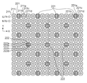
図2は2次元CMOSエリアセンサの縦(Y方向)13行と横(X方向)15列の範囲を、撮影光学系から観察した状態を示している。カラーフィルタはベイヤー配列が適用され、奇数行の画素には、左から順に緑(Green)と赤(Red)のカラーフィルタが交互に設けられる。また、偶数行の画素には、左から順に青(Blue)と緑(Green)のカラーフィルタが交互に設けられる。211i、221i等の円はオンチップマイクロレンズを表わす。オンチップマイクロレンズの内側に配置された複数の矩形はそれぞれ光電変換部である。 FIG. 2 shows a state in which a range of 13 rows in the vertical direction (Y direction) and 15 columns in the horizontal direction (X direction) of the two-dimensional CMOS area sensor is observed from the photographing optical system. A Bayer arrangement is applied to the color filters, and green (Red) and red (Red) color filters are alternately provided in order from the left on pixels in odd rows. In addition, blue (Blue) and green (Green) color filters are alternately provided in order from the left in the pixels in even rows. Circles such as 211i and 221i represent on-chip microlenses. Each of the plurality of rectangles arranged inside the on-chip microlens is a photoelectric conversion unit.
また、図中で黒くハッチングされた部分は単位画素内で遮光されている部分である。 Further, the black hatched portions in the figure are portions that are shielded from light within the unit pixel.
以下の説明では、単位画素内の各光電変換部を連結した形状を連結形状、当該連結形状の中心を連結中心と称する。 In the following description, a shape in which the photoelectric conversion units in the unit pixel are connected is referred to as a connection shape, and the center of the connection shape is referred to as a connection center.
211は第1の画素で、X方向とY方向にそれぞれ2分割された計4個の光電変換部211a〜211dを有する。これら光電変換部211a〜211dは、画素中心で直交するX軸及びY軸に対して、それぞれ線対称となるように分割されている。すなわち、各分割領域の平面形状は正方形、4個の領域を合わせた連結形状も正方形で、像面上のすべての位置において同一の形状となっている。第1の画素211で光電変換された出力信号は、画像データの生成用及び合焦位置近傍での焦点検出用に供される。ここで画像データには、JPEG等のフォーマットで規定された通常の2D(Dimensional)画像データのほかに、視差情報を含む複数の画像データから構成される3D画像データも含み、また動画データと静止画データのいずれも該当する。
A
第2の画素221、及び第3の画素222は、後述する第1の遮光部m1〜第4の遮光部m4が設けられている以外は第1の画素211と同等の構成を有している。
The
第2及び第3の各画素221,222は直交方向の被写体像(縦縞及び横縞パターン)をそれぞれ検出するもので、図示の画素配列では、第2の画素221は水平方向、第3の画素222は垂直方向の被写体像をそれぞれ検知する。
Each of the second and
図3及び図4は第2及び第3の各画素221,222の拡大図であり、単位画素における4個の光電変換部をa〜dで示している。
3 and 4 are enlarged views of the second and
第2及び第3の各画素221,222はそれぞれ、4個の光電変換部a〜dにまたがるような異なる形状の開口が形成された第1ないし第4の4種類の遮光部m1〜m4が設けられている。第1ないし第4の各遮光部m1〜m4のそれぞれには、画素ごとに4個の光電変換部a〜dを部分的にまたがるような第1ないし第4の異なる形状の開口n1〜n4が形成されている。そして、上記第1ないし第4の各遮光部m1〜m4のうち、第1の遮光部m1の第1の開口n1と第2の遮光部m2の第2の開口n2、並びに第3の遮光部m3の第3の開口n3と第4の遮光部m4の第4の開口n4はそれぞれ、画素中心で直交する2つのX軸、Y軸に対して、それぞれ線対称となるように形成される(図3及び図4参照)。
Each of the second and
そして、第2及び第3の各画素221,222では、4個の光電変換部a〜dの出力信号の加算方法が以下のように分類される。
(i)a、b、c、dの信号を加算
(ii)a、bの信号を加算
(iii)c、dの信号を加算
図5は、図3に示す遮光部m1、m2が設けられた画素を示している。
In each of the second and
(I) Add the signals a, b, c, d (ii) Add the signals a, b (iii) Add the signals c, d FIG. 5 is provided with the light shielding parts m1, m2 shown in FIG. The pixel is shown.
本実施形態では、図中の(A)画素と(B)画素のように部分的に遮光された画素を一対として互いの出力値の関係により焦点検出を行う。 In the present embodiment, focus detection is performed based on the relationship between the output values of a pair of partially shielded pixels such as the pixels (A) and (B) in the figure.
図5中のグラフは、均一な輝度の被写体を撮影した場合において、撮影光学系の入射瞳から(A)画素と(B)画素に射出される光線の角度を横軸に、それに対する光電変換強度の変化を縦軸で表したもので一般には瞳強度分布と呼ばれている。 The graph in FIG. 5 shows photoelectric conversion with respect to the angle of the light beam emitted from the entrance pupil of the photographing optical system to the (A) pixel and the (B) pixel when photographing a subject with uniform brightness. The change in intensity is represented by a vertical axis, which is generally called a pupil intensity distribution.
以下では(A)画素について説明を行うが、(B)画素は(A)画素に対して遮光部の形状(開口)が左右(ここではX軸方向)対称なだけであるため瞳強度分布も左右対称な特性となる。また、図4に示す遮光部m3,m4については、瞳強度は図5とは異なるものの、瞳強度分布は左右対称な特性となる。 In the following description, the (A) pixel will be described. However, the (B) pixel has only a symmetrical shape (aperture) of the light-shielding portion with respect to the (A) pixel. It is a symmetrical property. Further, for the light shielding portions m3 and m4 shown in FIG. 4, the pupil intensity distribution is symmetrical with respect to the pupil intensity distribution, although the pupil intensity is different from that in FIG.
図5中の瞳強度分布グラフにて破線で囲まれた(アa)及び(ア‘a)は、遮光部が設けられていない第1の画素211の出力値の上記(ii)及び(iii)の状態における瞳強度分布である。通常の2D画像データの撮像用に用いる場合は上記(i)のようにa〜dの各信号を加算して単一の画素の役割を持たせる。
(A) and (a′a) surrounded by a broken line in the pupil intensity distribution graph in FIG. 5 indicate the above (ii) and (iii) of the output value of the
また遮光部が設けられた状態において、(イa)は上記(ii)の状態における瞳強度分布、(ウa)は上記(iii)の状態における瞳強度分布である。また図5中の重複している瞳強度分布領域は加算されて2倍の強度を有するようになる。 In the state where the light shielding portion is provided, (a) is the pupil intensity distribution in the state (ii), and (a) is the pupil intensity distribution in the state (iii). Further, the overlapping pupil intensity distribution regions in FIG. 5 are added to have twice the intensity.
このように各光電変換部の出力信号の加算方法を変化させることにより、見かけ上遮光部の短辺の長さ(スリット幅)を変化させたような作用を付与することができる。 In this way, by changing the method of adding the output signals of the respective photoelectric conversion units, it is possible to provide an action that apparently changes the length of the short side (slit width) of the light shielding unit.
[実施形態2]次に図6を参照して、実施形態2における固体撮像素子の画素構成について説明する。なお、実施形態2において、カラーフィルタ、画素及び光電変換部の構成及び配置並びに各画素の出力信号の利用方法は実施形態1と同様である。 [Embodiment 2] Next, referring to FIG. 6, the pixel configuration of a solid-state imaging device in Embodiment 2 will be described. In the second embodiment, the configuration and arrangement of the color filter, the pixel, and the photoelectric conversion unit and the method of using the output signal of each pixel are the same as those in the first embodiment.
図6中の第2及び第3の各画素621,622で光電変換された出力信号は、画像データの生成用及び合焦位置近傍での焦点検出用に供される。
The output signals photoelectrically converted by the second and
ここで第2及び第3の各画素621,622は、直交方向(縦縞及び横縞模様)の被写体像を後述する光電変換部の信号の加算方法により選択的に検出する。
Here, each of the second and
図7及び図8は第2及び第3の各画素621,622の拡大図であり、単位画素における4個の光電変換部をa〜dで示している。
7 and 8 are enlarged views of the second and
第2及び第3の各画素621,622には、実施形態1とは異なり、異なる形状の複数の開口を有し、各画素621,622の複数の光電変換部621a〜d,622a〜dを部分的に遮光する第1ないし第4の4種類の遮光部p1〜p4が設けられている。第1ないし第4の各遮光部p1〜p4のそれぞれには、4個の光電変換部a〜dのうち、隣接する一対の光電変換部aとb、cとdを部分的にまたがるような異なる形状を有する第1の開口q1x〜q4xと第2の開口q1y〜q4yが形成されている。そして、上記第1ないし第4の各遮光部p1〜p4のうち、第1の遮光部p1の第1及び第2の開口q1x,q1yと第2の遮光部p2の第1及び第2の開口q2x,q2y、第3の遮光部p3の第1及び第2の開口q3x,q3yと第4の遮光部p4の第1及び第2の開口q4x,q4yはそれぞれ、画素中心で直交する2つのX軸、Y軸に対して、それぞれ線対称となるように形成される(図7及び図8参照)。
Unlike the first embodiment, each of the second and
そして、第2及び第3の各画素621,622では、4個の光電変換部a〜dの出力信号の加算方法が以下のように分類される。
(i)a、b、c、dの信号を加算
(ii)a、bの信号を加算
(iii)c、dの信号を加算
(iv)cまたはdの信号
図9は、図7における遮光部p1,p2が設けられた画素の瞳強度分布を示している。以下では(A)画素について説明を行うが、(B)画素は(A)画素に対して遮光部の開口が左右(ここではX軸方向)対称なだけであるため瞳強度分布も左右対称な特性となる。また、図8に示す遮光部p3,p4については、瞳強度は図9とは異なるものの、瞳強度分布は左右対称な特性となる。
In each of the second and
(I) a, b, c, adding signals d (ii) a, adding signals b (iii) c, adds the signal d (iv) signal c or d 9 are shading in FIG. 7 The pupil intensity distribution of the pixel provided with the parts p1 and p2 is shown. In the following description, the pixel (A) will be described. However, in the pixel (B), the aperture of the light shielding part is only symmetrical with respect to the pixel (A), and the pupil intensity distribution is also symmetrical with respect to the pixel. It becomes a characteristic. Further, regarding the light shielding portions p3 and p4 shown in FIG. 8, the pupil intensity distribution is symmetrical with respect to the pupil intensity distribution, although the pupil intensity is different from that in FIG.
そして、図中の(A)画素と(B)画素のように部分的に遮光された画素を一対として互いの出力値の関係により焦点検出を行う。 Then, focus detection is performed based on the relationship between the output values of a pair of partially shielded pixels such as the pixels (A) and (B) in the figure.
図9中の瞳強度分布グラフの破線で囲まれた(アa)及び(ア’a)は、上記(i)の状態における遮光部が設けられていない画素の瞳強度分布である。 (A) and (A'a) surrounded by a broken line in the pupil intensity distribution graph in FIG. 9 are pupil intensity distributions of pixels in which the light-shielding portion is not provided in the state (i).
また遮光部が設けられた状態において、(エa)は上記(ii)の状態における瞳強度分布、(オa)は上記(iii)の状態における瞳強度分布である。 In the state where the light shielding portion is provided, (a) is the pupil intensity distribution in the state (ii), and (o a) is the pupil intensity distribution in the state (iii).
また図9中の重複している瞳強度分布領域は加算されて2倍の強度を有するようになる。 Also, the overlapping pupil intensity distribution regions in FIG. 9 are added to have twice the intensity.
このように遮光された各光電変換部の出力信号の加算方法を変化させることにより、見かけ上遮光部の長辺及び短辺の長さ(スリット長及びスリット幅)を変化させたような作用を付与することができる。 By changing the method of adding the output signals of the respective light-shielded photoelectric conversion units in this way, the effect of apparently changing the long side and the short side length (slit length and slit width) of the light-shielding unit is obtained. Can be granted.
ここで、第2及び第3の各画素621,622の遮光部の開口をスリット状に形成する理由を説明する。
Here, the reason why the openings of the light shielding portions of the second and
位相差検出方式の焦点検出では、撮影光学系の射出瞳上で焦点検出用光束の瞳分割を行うが、瞳分割方向における瞳寸法が大きい場合には焦点検知像のボケが大きくなりすぎて焦点検出可能範囲が狭くなってくる。 In focus detection using the phase difference detection method, pupil division of the focus detection light beam is performed on the exit pupil of the imaging optical system. However, if the pupil size in the pupil division direction is large, the focus detection image becomes too blurred and the focus is increased. The detectable range becomes narrower.
また、撮影光学系のF値が暗く(Fナンバーが大きい)なってくると焦点検出用光束のケラレが大きくなり、一対の焦点検知用信号の相似性が損なわれてくるため焦点検出能力が低下してくる。更にこのケラレ現象はデフォーカス量に依存するため、デフォーカス量が大きいときには焦点検出能力が一層低下してしまう。 Also, vignetting of F values is dark (F-number is large) becomes come when focus detection light beam of the photographing optical system becomes large, the focus detection capability for similarity of the pair of focus detection signals being impaired reduction Come on. Further, since this vignetting phenomenon depends on the defocus amount, the focus detection capability is further deteriorated when the defocus amount is large.
ここで、撮影光学系の射出瞳面上における焦点検出用瞳と、固体撮像素子の各画素における光電変換部とは、オンチップマイクロレンズを介して共役関係にある。そこで、焦点検出用画素の開口をスリット形状として評価しうる被写体の縞パターン方向を開口の短辺方向とすることで、焦点検出用の瞳分割方向における瞳寸法を小さくすることで上記焦点検出能力の低下を回避する。 Here, the focus detection pupil on the exit pupil plane of the photographing optical system and the photoelectric conversion unit in each pixel of the solid-state imaging device are in a conjugate relationship via an on-chip microlens. Therefore, the focus detection capability can be achieved by reducing the pupil size in the pupil division direction for focus detection by setting the stripe pattern direction of the subject that can be evaluated as a slit shape for the aperture of the focus detection pixel to the short side direction of the aperture. To avoid the decline.
他方、合焦位置近傍、すなわちデフォーカス量が小さい場合には焦点検出用瞳の寸法が大きくとも焦点検知像のボケは小さいものとなる。 On the other hand, when the focus detection pupil area is small, that is, when the defocus amount is small, the blur of the focus detection image is small even if the size of the focus detection pupil is large.
よって、現在撮像を行っている被写体像が合焦位置近傍であると判断された場合には、光電変換部a、b、c、dの出力信号を全て加算した出力値を焦点検出用信号とすればよい。 Therefore, when it is determined that the subject image currently being captured is in the vicinity of the in-focus position, an output value obtained by adding all the output signals of the photoelectric conversion units a, b, c, and d is used as a focus detection signal. do it.
また更には、第1の画素211の出力信号も焦点検出に用いることで、焦点検出に用いる焦点検出用信号の情報量が増加し、画素出力のノイズの影響が低減され、焦点検出精度がより一層向上できる。
Furthermore, by using the output signal of the
[読み出し回路構成]次に図10を参照して、本実施形態の固体撮像素子における読み出し回路の構成について説明する。図10において、151は水平走査回路、153は垂直走査回路である。そして各画素の境界部には、水平走査ライン152aないし152dと、垂直走査ライン154aないし154dが配線され、各画素の光電変換部から上記各走査ラインを介して画素信号が読み出される。 [Readout Circuit Configuration] Next, with reference to FIG. 10, the configuration of the readout circuit in the solid-state imaging device of this embodiment will be described. In FIG. 10, 151 is a horizontal scanning circuit, and 153 is a vertical scanning circuit. In addition, horizontal scanning lines 152a to 152d and vertical scanning lines 154a to 154d are wired at the boundaries between the pixels, and pixel signals are read out from the photoelectric conversion units of the pixels via the scanning lines.
上記4個の光電変換部を有した画素は全て同様な構造となっており、撮像用画素と焦点検出用画素に応じて光電変換部の数が異なるような複雑な構造にはしていない。 All the pixels having the four photoelectric conversion units have the same structure, and are not configured to have a complicated structure in which the number of photoelectric conversion units differs depending on the imaging pixel and the focus detection pixel.
図中の配線構造は簡略化のため同じ線幅で示しているが、後述するように画素内での線幅を変えることで遮光部の役割を有するように設定を行う。 The wiring structure in the figure is shown with the same line width for simplification, but setting is performed so as to function as a light shielding portion by changing the line width in the pixel as will be described later.
なお、本実施形態の固体撮像素子は第1及び第2の2種類の読み出しモードを有する。第1の読み出しモードは全画素読み出しモードと称し、高精細静止画を撮像するために全画素の信号が読み出される。 Note that the solid-state imaging device of this embodiment has first and second types of readout modes. The first readout mode is referred to as an all-pixel readout mode, and all pixel signals are read out in order to capture a high-definition still image.
第2の読み出しモードは間引き読み出しモードと称し、動画又はプレビュー画像の表示のみを行うためのモードである。この場合に必要な画素数は全画素よりも少ないため、第1の画素211はX方向及びY方向ともに所定比率に間引いた画素のみ読み出す。また第2及び第3の各画素221,222,621,622からすべての信号を読み出すことで、焦点検出機能は維持される。
The second readout mode is referred to as a thinning readout mode, and is a mode for displaying only a moving image or a preview image. Since the number of pixels required in this case is smaller than the total number of pixels, the
図11は本実施形態の画素群における焦点検出用画素の断面構造を模式的に示している。詳細は特開2009−244862号公報に記載された通りであり、この公知技術を本実施形態に適用している。 FIG. 11 schematically shows a cross-sectional structure of the focus detection pixel in the pixel group of this embodiment. Details are as described in Japanese Patent Application Laid-Open No. 2009-244862, and this known technique is applied to this embodiment.
図11中、光電変換部302は、シリコン基板301に埋め込まれている。透明ポリシリコン電極303が光電変換部302とシリコン基板301の上面に設けられる。
In FIG. 11, the
多層構造を有する第1ないし第3の各電極群304〜306は、透明ポリシリコン電極303の上方に設けられる。第3の電極群306は各画素の境界部に配置されている。これら3層の電極群304〜306はアルミニウムもしくは銅等の金属膜をエッチングして形成される。
The first to
また、第1ないし第3の各電極群304〜306は、二酸化珪素(SiO2)等からなる透明な層間絶縁膜307によって絶縁されている。308は第3の電極群306の上部を覆うパッシベーション膜、309は第1の平坦化層である。310はカラーフィルタである。311は第2の平坦化層、312はマイクロレンズである。
The first to
撮像用画素と焦点検出用画素とは、画素内における第1の電極群304及び第2の電極群305の形状が異なっている。
The shape of the
焦点検出用画素にスリット状の開口を形成するように第1及び第2の各電極群304,305の幅が隣接する電極間の絶縁領域も考慮すると、撮像用画素の幅OP0に対し図中のOP1及びOP2のようにレイアウトされる。
In consideration of the insulating region between adjacent electrodes, the width of each of the first and
このように本実施形態では、第1及び第2の各電極群304,305を遮光膜として用いて画素に瞳分割機能を付与し、焦点検出用画素を形成している。
As described above, in this embodiment, the first and
他方、撮像用画素は、第1及び第2の各電極群304,305が破線で示した長さになっており、図中のOP0で示した開口領域として光電変換部に十分に導光されるようにレイアウトされる。
On the other hand, in the imaging pixel, each of the first and
なお、図11は一方向の断面のみを示しているが、この断面と直交する方向(奥行き方向)について、第2の電極群305も第1の電極群304と同様に画素の仕様に合わせて電極の幅や形状が設定される。
Note that FIG. 11 shows only a cross section in one direction, but the
このように、光電変換部の構成を撮像用画素と焦点検出用画素とで特に差異を設けなくとも、上記遮光部や構成(上述の例では配線の幅を変化させる構成)を焦点検出用画素に施し、光電変換部の信号の加算方法を変えることにより、電気的な構造を複雑化することなく撮像用画素と焦点検出用画素をレイアウトすることができる。 In this way, even if there is no particular difference in the configuration of the photoelectric conversion unit between the imaging pixel and the focus detection pixel, the light shielding unit and the configuration (configuration in which the width of the wiring is changed in the above example) are used as the focus detection pixel. In addition, by changing the signal addition method of the photoelectric conversion unit, the imaging pixels and the focus detection pixels can be laid out without complicating the electrical structure.
図12は、撮影光学系の一次元方向(例えばX方向)の位相差検出用画素(焦点検出用画素)の瞳投影を説明する図である。 FIG. 12 is a diagram illustrating pupil projection of a phase difference detection pixel (focus detection pixel) in a one-dimensional direction (for example, the X direction) of the photographing optical system.
図12では、図11で示した画素構造(一部簡略化している)を左右方向に反転させた向きでの2つの画素(a)及び(b)を一対として被写体像の位相差を検知する。 In FIG. 12, the phase difference of the subject image is detected with a pair of two pixels (a) and (b) in a direction in which the pixel structure (partially simplified) shown in FIG. .
図11で示した構造で設定される開口OP0は、マイクロレンズ312を介して図12に示す撮影光学系の射出瞳TLの瞳EP0a及びEP0bとして投影される。 The opening OP0 set with the structure shown in FIG. 11 is projected as pupils EP0a and EP0b of the exit pupil TL of the photographing optical system shown in FIG.
他方、焦点検出用画素では遮光部の開口が図12のOP1及びOP2に規制されている。このため、瞳EP0a及びEP0bの領域内にOP1に対応した瞳は図12のEP1a及びEP1b、同様にOP2に対応した瞳はEP2a及びEP2bとなるように瞳が分割され、その瞳領域を通過した光束を画素(a)及び(b)が受光する。 On the other hand, in the focus detection pixel, the opening of the light shielding portion is restricted to OP1 and OP2 in FIG. For this reason, the pupil corresponding to OP1 is divided into EP1a and EP1b in FIG. 12 in the region of pupils EP0a and EP0b, and similarly, the pupil corresponding to OP2 is divided into EP2a and EP2b and passed through the pupil region. Pixels (a) and (b) receive the luminous flux.
そして、画素(a)及び画素(b)は、図2及び図6に示したように水平方向および/または垂直方向に規則的に配列されている。そこで、複数の画素(a)の出力信号を連ねて生成した第1の像信号と、複数の画素(b)の出力信号を連ねて生成した第2の像信号との像ずれ量、すなわち位相差を検出することで被写体像のデフォーカス量が検出できる。 The pixels (a) and (b) are regularly arranged in the horizontal direction and / or the vertical direction as shown in FIGS. Therefore, the amount of image shift between the first image signal generated by combining the output signals of the plurality of pixels (a) and the second image signal generated by combining the output signals of the plurality of pixels (b), that is, the position. By detecting the phase difference, the defocus amount of the subject image can be detected.
本実施形態では、固体撮像素子の全面にわたって、各画素が複数の光電変換部を有し、各光電変換部は1つのマイクロレンズを通じて受光を行うため、各光電変換部とマイクロレンズの光軸との位置関係はそれぞれが異なったものになる。そのため、各光電変換部に入射する被写体像はそれぞれがズレを生じたものを受光していることとなる。 In the present embodiment, each pixel has a plurality of photoelectric conversion units over the entire surface of the solid-state imaging device, and each photoelectric conversion unit receives light through one microlens. Therefore, each photoelectric conversion unit and the optical axis of the microlens The positional relationships of are different from each other. For this reason, the subject images incident on the photoelectric conversion units receive light that is shifted.
そこで画素内の全ての光電変換部の信号を加算して扱えば解像度は低下するが通常の2D画像データとして用いることができる。 Therefore, if the signals of all the photoelectric conversion units in the pixel are added and handled, the resolution is lowered, but it can be used as normal 2D image data.
他方、本実施形態の画素構成によれば、1画素中の4つの光電変換部で水平方向または垂直方向に隣接する光電変換部の出力信号を加算して1つの画素から2つの像信号を分けて出力する。これにより、上述したように各像信号で再現される被写体像の視差画像を取得できるので、以下の方法で3D画像データを生成することが可能である。 On the other hand, according to the pixel configuration of the present embodiment, the output signals of the photoelectric conversion units adjacent in the horizontal direction or the vertical direction are added by the four photoelectric conversion units in one pixel to divide two image signals from one pixel. Output. Thereby, since the parallax image of the subject image reproduced by each image signal can be acquired as described above, 3D image data can be generated by the following method.
[3D画像データの生成方法]図13は、焦点検出時に取得された画像と焦点検出信号、並びに焦点検出結果から得られたデフォーカスマップを示している。図13(a)において、撮像面に形成された被写体像には、中央に近景の人物、左側に中景の樹木、右側に遠景の山並みが写っている。以下、図13における焦点検出信号として、第3の画素222の信号を採用した場合について説明する。
[Method for
図13(a)においては、画面中央に人物の顔が存在している。そこで公知の顔認識技術によって顔の存在が検出されると、顔領域を中心に第3の画素222による一対の焦点検出用信号AFb及びAFcが得られる。また、顔以外の領域は、所定ピッチで焦点検出領域が撮影画面全面にわたって設定される。図13(a)の左は木の幹に対応した焦点検出領域とその信号が、右上には山の稜線に対応した焦点検出領域とその信号が示されている。そして、各焦点検出領域にて得られた一対の信号はそれぞれ横ずれしているため、公知の相関演算により横ずれ量を計算し、さらに上記横ずれ量を基線長で除算を行うことでデフォーカス量を算出する。
In FIG. 13A, a human face exists in the center of the screen. Therefore, when the presence of a face is detected by a known face recognition technique, a pair of focus detection signals AFb and AFc by the
その後、主被写体、図13(a)では中央に位置する顔領域について、デフォーカス量がゼロとなるように撮影光学系のフォーカスレンズを駆動し、再度焦点検出を行う。 Thereafter, the focus lens of the photographing optical system is driven so that the defocus amount is zero for the main subject, that is, the face region located at the center in FIG.
以上の焦点調節過程で、撮影画面全面における焦点ずれ情報、いわゆるデフォーカスマップが取得できるが、その一例を図13(b)に示す。図13(b)は、デフォーカス量を所定の分解能に基づいて整理統合し、デフォーカス量の小さい領域から順に、DEF0ないしDEF3に統合した例である。 Through the above-described focus adjustment process, defocus information on the entire photographing screen, so-called defocus map, can be acquired. An example is shown in FIG. FIG. 13B shows an example in which the defocus amounts are consolidated and integrated based on a predetermined resolution, and are integrated into DEF0 to DEF3 in order from the region with the smallest defocus amount.
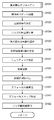
[撮影処理]図14ないし図16のほか、図1ないし図13を参照しながら、本実施形態のカメラによる撮影処理について説明する。以下に説明するフローチャートは、CPU121がROMに格納されたプログラムをRAMのワークエリアに展開することにより実行される。
[Shooting Process] The shooting process by the camera of the present embodiment will be described with reference to FIGS. 1 to 13 in addition to FIGS. The flowchart described below is executed by the
図14は実施形態1によるメインルーチンの撮影処理を示すフローチャートである。 FIG. 14 is a flowchart showing the shooting process of the main routine according to the first embodiment.
図14において、撮影者がカメラの電源スイッチをオン操作すると、ステップS102では、CPU121はカメラ内の各アクチュエータや固体撮像素子の動作確認を行い、メモリ内容や実行プログラムの初期化を行うと共に、撮影準備動作を実行する。
In FIG. 14, when the photographer turns on the power switch of the camera, in step S102, the
ステップS103では、CPU121は撮影条件の設定受付け処理を行う。具体的には、露光調節モード、焦点調節モード、画像記録モード(2D又は3D)、画質(記録画素数や圧縮率)等を撮影者による設定操作を受け付ける。
In step S103, the
ステップS104では、CPU121は画像記録モードを判定し、3D画像記録モードが設定されていたら、ステップS105にて、撮影時の絞り値を開放に設定する。ここで、3D画像記録モードの場合は一対の画像が適正な視差情報を有していることが必要だが、光量調節のために撮影光学系の絞りを小絞りにしてしまうと、視差情報が減少してしまう。よって、3D画像記録モードでは絞りを開放に固定し、露光量は固体撮像素子の蓄積時間にて調節する。
In step S104, the
一方、ステップS104にて2D画像記録モードに設定されていたら、CPU121はステップS106にて絞り値を指定値に制御する。ここでの指定値とは、絞り優先AEでは撮影者が選択した絞り値、プログラムAEでは予め設定された露出制御プログラムに基づく絞り値となる。
On the other hand, if the 2D image recording mode is set in step S104, the
ステップS107では、CPU121は撮影光学系のズーム状態、フォーカスレンズ状態、及び絞り状態を検出し、射出瞳の大きさや射出瞳距離等の情報をROMから読み出す。
In step S107, the
ステップS108では、CPU121は固体撮像素子の撮像動作を開始し、画素信号を読み出す。
In step S108, the
ステップS109では、CPU121は読み出した画素信号から表示用縮小画像を生成し、カメラ本体の背面に設けられた表示器131に表示する。すると撮影者はこのプレビュー画像を目視して構図決定やズーム操作等を行う。
In step S109, the
ステップS131では、CPU121は後述する焦点検出処理を実行する。
In step S131, the
ステップS151では、CPU121はステップS131で算出したフォーカスレンズ駆動量が所定値以下か否かを判定する。そして駆動量が所定値以下の場合は合焦と判定しステップS153に移行するが、所定値を超えている場合はステップS152でフォーカスレンズを駆動する。
In step S151, the
ステップS153では、CPU121は撮影スイッチがオンされたか否かを判定し、オンされていなければステップS181に移行し、オンされた場合はステップS161にて後述する画像記録処理を実行する。
In step S153, the
ステップS181では、CPU121はメインスイッチの状態を判定し、オン状態が維持されている場合はステップS102に戻り、オフされたらステップS182に移行する。
In step S181, the
ステップS182では、CPU121はステップS161で記録された画像データを、インターネット回線を介してサーバーコンピュータに送信する。するとサーバーコンピュータでは、3D画像データの視差情報の再構成や、デフォーカスマップの高精度演算等、演算規模の大きな処理を実行する。
In step S182, the
ステップS183では、CPU121はサーバーコンピュータで処理した画像データを受信する。
In step S183, the
ステップS184では、CPU121はステップS161で記録した元画像データに対して、サーバーコンピュータで処理した修正部分の追加や置き換え修正を行い、撮影処理を終了する。
In step S184, the
<焦点検出処理>図15は図14のステップS131におけるサブルーチンの焦点検出処理を示すフローチャートである。図14のステップS131から焦点検出サブルーチンへ移行すると、ステップS132において、CPU121はプレビュー画像から被写体パターンを認識し、顔画像の判別や、撮影画面全体のコントラスト分析等を行う。
<Focus Detection Processing> FIG. 15 is a flowchart showing the focus detection processing of the subroutine in step S131 of FIG. When the process proceeds from step S131 in FIG. 14 to the focus detection subroutine, in step S132, the
ステップS133では、CPU121はステップS132での認識結果から、焦点を合わせるべき主被写体を決定する。
In step S133, the
ステップS134では、CPU121はステップS107で取得したレンズ情報に基づき、撮影光学系の射出瞳計算を行う。具体的には、射出瞳の大きさや像面からの距離を算出し、次いで像高毎のビネッティング計算を行う。
In step S134, the
ステップS135では、CPU121はステップS134で計算した射出瞳情報に基づき、焦点検出エリアごとに、ケラレの影響が少ない画素群を選択する。
In step S135, the
ステップS136では、CPU121は選択された画素群の各光電変換部の出力信号から相関演算用の一対2像を生成する。なお、ここで選択される画素群は1種類には限定されず、ビネッティングの影響が少ない画素群であれば、複数種を選択する。
In step S136, the
ステップS137では、CPU121は生成した焦点検出信号に対して、ビネッティングにより生じた光量アンバランスを軽減する、いわゆるシェーディング補正を施す。これにより、2像の強度差が軽減され、焦点検出精度が向上する。
In step S137, the
ステップS138では、CPU121はシェーディング補正が施された2像の横ずれ量uを算出するための相関演算を行う。
In step S138, the
ステップS139では、CPU121はステップS138での相関演算の過程で算出された2像の一致度から、像ずれ検出結果の信頼性を判定し、信頼性の低い値は不採用とする。
In step S139, the
ステップS140では、CPU121はステップS138及びS139にて得られた信頼性の高い像ずれ量と、焦点検出に用いた画素群の基線長から、像ずれ量を基線長で除算することによりデフォーカス量を算出する。
In step S140, the
ステップS141では、CPU121は撮影領域全域におけるデフォーカスマップを作成する。なお、デフォーカスマップの分解能(平面方向及び奥行き方向)を高くすると演算時間も増加するため、動画の記録レートに影響を及ぼさない程度の分解能に設定する。そして、詳細なデフォーカスマップが必要な場合は、図14のステップS182で説明したように、高性能のサーバーコンピュータにて実施すればよい。
In step S141, the
ステップS142では、CPU121はステップS133で決定した主被写体領域と、ステップS141で作成したデフォーカスマップに基づき、フォーカスレンズの駆動量を算出する。その後、図14のメインルーチンにリターンする。
In step S142, the
<画像記録処理>図16は図14のステップS161におけるサブルーチンの画像記録処理を示すフローチャートである。 <Image Recording Process> FIG. 16 is a flowchart showing the subroutine image recording process in step S161 of FIG.
図16において、撮影スイッチがオン操作され、図14のステップS161から画像記録サブルーチンへ移行すると、CPU121はステップS162にてカメラの姿勢検知を行う。
In FIG. 16, when the shooting switch is turned on and the process proceeds from step S161 in FIG. 14 to the image recording subroutine, the
ステップS163では、CPU121は姿勢検知結果に基づき、重力方向に応じた光電変換部の加算と画素の補間処理を行う。
In step S163, the
ステップS164では、CPU121は所定のフォーマットに則った3D画像データを生成する。
In step S164, the
ステップS165では、CPU121はステップS164で生成した画像データから、視差情報を消去した通常の2D画像データを生成する。例えば、一対の画像における同一座標の画素情報同士を加算することで、視差情報が消失した2D画像データが得られる。
In step S165, the
ステップS166では、CPU121はステップS164及びS165で生成した画像データに所定の圧縮処理を施し、フラッシュメモリ133に記録する。
In step S166, the
ステップS167では、CPU121は図14のステップS141で作成したデフォーカスマップを画像に関連付けて記録する。その後、図14のメインルーチンにリターンする。
In step S167, the
以上説明したように、本実施形態によれば、電気的な構造を複雑化することなく撮像用画素と焦点検出用画素をレイアウトすることができる。 As described above, according to the present embodiment, the imaging pixels and the focus detection pixels can be laid out without complicating the electrical structure.
[他の実施形態]本発明は、以下の処理を実行することによっても実現される。即ち、上記実施形態の機能を実現するソフトウェア(プログラム)をネットワーク又は各種記憶媒体を介してシステム或いは装置に供給し、そのシステム或いは装置のコンピュータ(又はCPUやMPU等)がプログラムコードを読み出して実行する処理である。この場合、そのプログラム、及び当該プログラムを記憶した記憶媒体は本発明を構成することになる。 [Other Embodiments] The present invention is also realized by executing the following processing. That is, software (program) that realizes the functions of the above-described embodiments is supplied to a system or apparatus via a network or various storage media, and a computer (or CPU, MPU, etc.) of the system or apparatus reads and executes the program code. It is processing to do. In this case, the program and the storage medium storing the program constitute the present invention.
Claims (8)
前記画素群の一部に焦点検出用画素として、前記複数の光電変換部のそれぞれを部分的に遮光する遮光部を設け、
前記遮光部は、異なる形状の複数の開口を有し、当該開口は前記複数の光電変換部のうち、隣接する一対の光電変換部を部分的にまたがるように形成されることを特徴とする固体撮像素子。 A solid-state imaging device including a pixel group in which unit pixels each having a microlens and a plurality of photoelectric conversion units are two-dimensionally arranged, the pixel group including an imaging pixel and a focus detection pixel;
As a focus detection pixel in a part of the pixel group, a light shielding part that partially shields each of the plurality of photoelectric conversion parts is provided ,
The light-shielding portion has a plurality of openings having different shapes, and the openings are formed so as to partially span a pair of adjacent photoelectric conversion portions among the plurality of photoelectric conversion portions. Image sensor.
前記第1ないし第4の各遮光部のそれぞれには、第1の開口と第2の開口が形成され、
前記第1の遮光部の第1及び第2の開口と第2の遮光部の第1及び第2の開口、並びに第3の遮光部の第1及び第2の開口と第4の遮光部の第1及び第2の開口はそれぞれ、画素中心で直交する2つの軸に対して、それぞれ線対称となるように形成されることを特徴とする請求項1に記載の固体撮像素子。 The focus detection pixel is provided with any one of first to fourth light shielding portions,
A first opening and a second opening are formed in each of the first to fourth light shielding portions,
The first and second openings of the first light shielding part and the first and second openings of the second light shielding part, and the first and second openings of the third light shielding part and the fourth light shielding part. 2. The solid-state imaging device according to claim 1 , wherein each of the first and second openings is formed to be line-symmetric with respect to two axes orthogonal to each other at the pixel center.
前記焦点検出用画素からの信号を用いて焦点検出を行う焦点検出手段と、
前記焦点検出手段による検出結果に応じて合焦状態になるように光学系を制御する制御手段と、を有することを特徴とする撮像装置。 A solid-state imaging device according to any one of claims 1 to 3 ,
Focus detection means for performing focus detection using a signal from the focus detection pixel;
An image pickup apparatus comprising: control means for controlling an optical system so as to be in a focused state in accordance with a detection result by the focus detection means.
Priority Applications (3)
| Application Number | Priority Date | Filing Date | Title |
|---|---|---|---|
| JP2011082189A JP5825817B2 (en) | 2011-04-01 | 2011-04-01 | Solid-state imaging device and imaging apparatus |
| US13/428,515 US9025060B2 (en) | 2011-04-01 | 2012-03-23 | Solid-state image sensor having a shielding unit for shielding some of photo-electric converters and image capturing apparatus including the solid-state image sensor |
| US14/685,097 US20150222834A1 (en) | 2011-04-01 | 2015-04-13 | Solid-state image sensor and image capturing apparatus |
Applications Claiming Priority (1)
| Application Number | Priority Date | Filing Date | Title |
|---|---|---|---|
| JP2011082189A JP5825817B2 (en) | 2011-04-01 | 2011-04-01 | Solid-state imaging device and imaging apparatus |
Publications (3)
| Publication Number | Publication Date |
|---|---|
| JP2012215785A JP2012215785A (en) | 2012-11-08 |
| JP2012215785A5 JP2012215785A5 (en) | 2014-05-15 |
| JP5825817B2 true JP5825817B2 (en) | 2015-12-02 |
Family
ID=46926776
Family Applications (1)
| Application Number | Title | Priority Date | Filing Date |
|---|---|---|---|
| JP2011082189A Active JP5825817B2 (en) | 2011-04-01 | 2011-04-01 | Solid-state imaging device and imaging apparatus |
Country Status (2)
| Country | Link |
|---|---|
| US (2) | US9025060B2 (en) |
| JP (1) | JP5825817B2 (en) |
Families Citing this family (36)
| Publication number | Priority date | Publication date | Assignee | Title |
|---|---|---|---|---|
| CN103460703B (en) * | 2011-03-24 | 2015-03-11 | 富士胶片株式会社 | Color image capturing element and image capturing device |
| JP5956782B2 (en) * | 2011-05-26 | 2016-07-27 | キヤノン株式会社 | Imaging device and imaging apparatus |
| US8896125B2 (en) * | 2011-07-05 | 2014-11-25 | Sony Corporation | Semiconductor device, fabrication method for a semiconductor device and electronic apparatus |
| JP6000520B2 (en) * | 2011-07-25 | 2016-09-28 | キヤノン株式会社 | Imaging apparatus and control method and program thereof |
| JP2013145779A (en) * | 2012-01-13 | 2013-07-25 | Sony Corp | Solid-state imaging device and electronic apparatus |
| JP5967944B2 (en) | 2012-01-18 | 2016-08-10 | キヤノン株式会社 | Solid-state imaging device and camera |
| US9191566B2 (en) * | 2012-03-30 | 2015-11-17 | Samsung Electronics Co., Ltd. | Image pickup apparatus, method for image pickup and computer-readable recording medium |
| CN105359519B (en) | 2013-07-05 | 2017-07-04 | 株式会社尼康 | Camera head |
| US9503698B2 (en) | 2013-08-01 | 2016-11-22 | Harvest Imaging bvba | Image sensor with shading detection |
| EP2833621B1 (en) * | 2013-08-01 | 2018-10-10 | Harvest Imaging bvba | Image sensor with shading detection |
| JP2015076475A (en) * | 2013-10-08 | 2015-04-20 | ソニー株式会社 | Solid-state imaging device, method of manufacturing the same, and electronic apparatus |
| JP6233188B2 (en) * | 2013-12-12 | 2017-11-22 | ソニー株式会社 | Solid-state imaging device, manufacturing method thereof, and electronic device |
| US10680022B2 (en) | 2013-12-12 | 2020-06-09 | Sony Corporation | Solid state imaging device, manufacturing method of the same, and electronic equipment |
| JP2015129846A (en) * | 2014-01-07 | 2015-07-16 | キヤノン株式会社 | Image capturing device and control method therefor |
| JP6312487B2 (en) * | 2014-03-26 | 2018-04-18 | キヤノン株式会社 | Image processing apparatus, control method therefor, and program |
| JP6381266B2 (en) * | 2014-04-15 | 2018-08-29 | キヤノン株式会社 | IMAGING DEVICE, CONTROL DEVICE, CONTROL METHOD, PROGRAM, AND STORAGE MEDIUM |
| JP6518071B2 (en) * | 2015-01-26 | 2019-05-22 | キヤノン株式会社 | Solid-state imaging device and camera |
| KR102299575B1 (en) | 2015-03-09 | 2021-09-07 | 삼성전자주식회사 | Image signal processor for generating depth map from phase detection pixels, and device having same |
| WO2016194501A1 (en) * | 2015-06-03 | 2016-12-08 | ソニー株式会社 | Solid-state image-capture element, image-capture element, and method for manufacturing solid-state image-capture element |
| KR102374112B1 (en) | 2015-07-15 | 2022-03-14 | 삼성전자주식회사 | An image sensor including an auto focusing pixel, and an image processing system including the same |
| TWI565323B (en) * | 2015-09-02 | 2017-01-01 | 原相科技股份有限公司 | Imaging device for distinguishing foreground and operating method thereof, and image sensor |
| WO2017039038A1 (en) * | 2015-09-04 | 2017-03-09 | 재단법인 다차원 스마트 아이티 융합시스템 연구단 | Image sensor to which multiple fill factors are applied |
| JP6758747B2 (en) * | 2015-09-18 | 2020-09-23 | ソニーセミコンダクタソリューションズ株式会社 | Solid-state image sensor and electronic equipment |
| US9986150B2 (en) * | 2015-09-30 | 2018-05-29 | Ricoh Co., Ltd. | Algorithm to estimate yaw errors in camera pose |
| GB2548462B (en) | 2016-01-29 | 2020-06-17 | Canon Kk | Image sensor and image capturing apparatus |
| JP2017195342A (en) * | 2016-04-22 | 2017-10-26 | 株式会社ニコン | Image pickup element and electronic apparatus |
| US11064144B2 (en) | 2016-06-06 | 2021-07-13 | Sony Corporation | Imaging element, imaging apparatus, and electronic equipment |
| WO2018003501A1 (en) * | 2016-06-28 | 2018-01-04 | ソニー株式会社 | Solid-state imaging device, electronic apparatus, lens control method, and vehicle |
| CN106454289B (en) * | 2016-11-29 | 2018-01-23 | 广东欧珀移动通信有限公司 | Control method, control device and electronic installation |
| CN106504218B (en) | 2016-11-29 | 2019-03-12 | Oppo广东移动通信有限公司 | Control method, control device and electronic device |
| KR102428834B1 (en) * | 2017-03-29 | 2022-08-03 | 삼성디스플레이 주식회사 | Display device |
| JP7058971B2 (en) * | 2017-10-10 | 2022-04-25 | キヤノン株式会社 | Image pickup device and its control method |
| US10608039B1 (en) * | 2018-10-02 | 2020-03-31 | Foveon, Inc. | Imaging arrays having focal plane phase detecting pixel sensors |
| US11025796B2 (en) * | 2019-01-14 | 2021-06-01 | Xerox Corporation | Plurality of linear sensor arrays comprising plural process direction widths and photosites with submicron y-axis alignment between arrays |
| JP7293025B2 (en) * | 2019-07-29 | 2023-06-19 | キヤノン株式会社 | Imaging device and its control method |
| US11729502B2 (en) * | 2021-04-28 | 2023-08-15 | Canon Kabushiki Kaisha | Apparatus including focusing function and method of the same |
Family Cites Families (35)
| Publication number | Priority date | Publication date | Assignee | Title |
|---|---|---|---|---|
| JPS60125814A (en) | 1983-12-13 | 1985-07-05 | Olympus Optical Co Ltd | Focusing detector |
| JP3753201B2 (en) * | 1996-07-22 | 2006-03-08 | 富士写真フイルム株式会社 | Parallax image input device |
| US7358999B2 (en) * | 1998-03-10 | 2008-04-15 | Canon Kabushiki Kaisha | Focus sensing apparatus, focus sensing method using phase-differential detection and computer-readable storage medium therefor |
| US6995800B2 (en) * | 2000-01-27 | 2006-02-07 | Canon Kabushiki Kaisha | Image pickup apparatus utilizing a plurality of converging lenses |
| US6750437B2 (en) * | 2000-08-28 | 2004-06-15 | Canon Kabushiki Kaisha | Image pickup apparatus that suitably adjusts a focus |
| EP1217826A3 (en) * | 2000-12-19 | 2005-05-25 | Konica Corporation | Image processing apparatus |
| JP4734779B2 (en) * | 2001-06-22 | 2011-07-27 | 株式会社ニコン | Solid-state imaging device |
| JP4125927B2 (en) * | 2002-08-16 | 2008-07-30 | 富士フイルム株式会社 | Solid-state imaging device and solid-state imaging device |
| JP4243462B2 (en) * | 2002-08-19 | 2009-03-25 | 富士フイルム株式会社 | SOLID-STATE IMAGING DEVICE AND LIGHT EMITTING ELEMENT RESPONSIBILITY OUTPUT CONTROL |
| JP4264248B2 (en) * | 2002-11-19 | 2009-05-13 | 富士フイルム株式会社 | Color solid-state imaging device |
| JP4236169B2 (en) * | 2003-09-10 | 2009-03-11 | 富士フイルム株式会社 | Solid-state imaging device |
| JP4236168B2 (en) * | 2003-09-10 | 2009-03-11 | 富士フイルム株式会社 | Solid-state imaging device |
| JP4490075B2 (en) * | 2003-10-28 | 2010-06-23 | 富士フイルム株式会社 | Solid-state imaging device and manufacturing method thereof |
| JP2006126652A (en) * | 2004-10-29 | 2006-05-18 | Canon Inc | Imaging apparatus |
| JP2007065330A (en) * | 2005-08-31 | 2007-03-15 | Canon Inc | Camera |
| JP4967296B2 (en) * | 2005-10-03 | 2012-07-04 | 株式会社ニコン | Imaging device, focus detection apparatus, and imaging system |
| JP4835136B2 (en) | 2005-12-06 | 2011-12-14 | 株式会社ニコン | Solid-state imaging device having a function for generating a focus detection signal, and an electronic camera |
| JP4720508B2 (en) * | 2006-01-05 | 2011-07-13 | 株式会社ニコン | Imaging device and imaging apparatus |
| JP4649623B2 (en) * | 2006-01-18 | 2011-03-16 | 国立大学法人静岡大学 | Solid-state imaging device and pixel signal reading method thereof |
| JP2007281144A (en) * | 2006-04-05 | 2007-10-25 | Fujifilm Corp | Solid state image sensor and imaging apparatus |
| WO2008032820A1 (en) * | 2006-09-14 | 2008-03-20 | Nikon Corporation | Imaging element and imaging device |
| JP5034556B2 (en) * | 2007-02-27 | 2012-09-26 | 株式会社ニコン | Focus detection apparatus and imaging apparatus |
| JP5040458B2 (en) * | 2007-06-16 | 2012-10-03 | 株式会社ニコン | Solid-state imaging device and imaging apparatus using the same |
| JP4957413B2 (en) * | 2007-07-04 | 2012-06-20 | 株式会社ニコン | Solid-state imaging device and imaging apparatus using the same |
| JP5451111B2 (en) | 2008-03-11 | 2014-03-26 | キヤノン株式会社 | Focus detection apparatus and imaging apparatus having the same |
| JP5225151B2 (en) * | 2008-03-11 | 2013-07-03 | キヤノン株式会社 | Imaging apparatus and image processing method |
| JP2009303043A (en) * | 2008-06-16 | 2009-12-24 | Panasonic Corp | Solid-state imaging device and signal processing method thereof |
| JP2010066494A (en) * | 2008-09-10 | 2010-03-25 | Olympus Corp | Solid imaging element and digital camera |
| JP2010094499A (en) * | 2008-09-16 | 2010-04-30 | Hitachi Maxell Ltd | Image acquisition apparatus and biometric information acquisition apparatus |
| JP5217880B2 (en) * | 2008-10-09 | 2013-06-19 | 株式会社ニコン | Imaging device |
| US8558940B2 (en) * | 2008-11-27 | 2013-10-15 | Nikon Corporation | Image sensor and image-capturing device |
| JP5532599B2 (en) * | 2008-12-17 | 2014-06-25 | 株式会社ニコン | Solid-state imaging device manufacturing method and imaging apparatus |
| US8570427B2 (en) * | 2009-01-28 | 2013-10-29 | Nikon Corporation | Image-capturing device having focus adjustment function, image creation method including focus adjustment function, and program product for image-capturing device having focus adjustment function |
| JP5229060B2 (en) * | 2009-03-31 | 2013-07-03 | ソニー株式会社 | Imaging apparatus and focus detection method |
| JP2011176715A (en) * | 2010-02-25 | 2011-09-08 | Nikon Corp | Back-illuminated image sensor and imaging apparatus |
-
2011
- 2011-04-01 JP JP2011082189A patent/JP5825817B2/en active Active
-
2012
- 2012-03-23 US US13/428,515 patent/US9025060B2/en active Active
-
2015
- 2015-04-13 US US14/685,097 patent/US20150222834A1/en not_active Abandoned
Also Published As
| Publication number | Publication date |
|---|---|
| US20150222834A1 (en) | 2015-08-06 |
| US9025060B2 (en) | 2015-05-05 |
| US20120249846A1 (en) | 2012-10-04 |
| JP2012215785A (en) | 2012-11-08 |
Similar Documents
| Publication | Publication Date | Title |
|---|---|---|
| JP5825817B2 (en) | Solid-state imaging device and imaging apparatus | |
| US9204067B2 (en) | Image sensor and image capturing apparatus | |
| KR101211960B1 (en) | Image pickup apparatus and control method therefor | |
| KR101240080B1 (en) | Focus detection device and imaging apparatus having the same | |
| US9742984B2 (en) | Image capturing apparatus and method of controlling the same | |
| JP5159700B2 (en) | Optical apparatus and focus detection method | |
| JP5675157B2 (en) | Focus detection device | |
| TWI462055B (en) | Cfa image with synthetic panchromatic image | |
| US8634015B2 (en) | Image capturing apparatus and method and program for controlling same | |
| US8363093B2 (en) | Stereoscopic imaging using split complementary color filters | |
| US8902349B2 (en) | Image pickup apparatus | |
| US20130107019A1 (en) | Imaging device, image processing device and image processing method | |
| JP7380777B2 (en) | Control devices, control methods, computer programs and electronic equipment | |
| WO2012073727A1 (en) | Imaging device and focal position detection method | |
| JP6671130B2 (en) | Imaging device, imaging device, focus detection device, image processing device, and control method therefor | |
| JP5850648B2 (en) | Imaging device | |
| JP5852371B2 (en) | Imaging apparatus and control method thereof | |
| JP5420050B2 (en) | Imaging apparatus and control method thereof | |
| JP2012220790A (en) | Imaging apparatus | |
| JP5486284B2 (en) | Imaging device | |
| JP2020057017A (en) | Image-capturing device and method for controlling the same | |
| JP2017102240A (en) | Image processing device and image processing method, imaging device, program | |
| JP6748529B2 (en) | Imaging device and imaging device |
Legal Events
| Date | Code | Title | Description |
|---|---|---|---|
| A521 | Request for written amendment filed |
Free format text: JAPANESE INTERMEDIATE CODE: A523 Effective date: 20140328 |
|
| A621 | Written request for application examination |
Free format text: JAPANESE INTERMEDIATE CODE: A621 Effective date: 20140328 |
|
| A977 | Report on retrieval |
Free format text: JAPANESE INTERMEDIATE CODE: A971007 Effective date: 20150129 |
|
| A131 | Notification of reasons for refusal |
Free format text: JAPANESE INTERMEDIATE CODE: A131 Effective date: 20150223 |
|
| A521 | Request for written amendment filed |
Free format text: JAPANESE INTERMEDIATE CODE: A523 Effective date: 20150423 |
|
| TRDD | Decision of grant or rejection written | ||
| A01 | Written decision to grant a patent or to grant a registration (utility model) |
Free format text: JAPANESE INTERMEDIATE CODE: A01 Effective date: 20150914 |
|
| A61 | First payment of annual fees (during grant procedure) |
Free format text: JAPANESE INTERMEDIATE CODE: A61 Effective date: 20151013 |
|
| R151 | Written notification of patent or utility model registration |
Ref document number: 5825817 Country of ref document: JP Free format text: JAPANESE INTERMEDIATE CODE: R151 |