JP5034556B2 - Focus detection apparatus and imaging apparatus - Google Patents
Focus detection apparatus and imaging apparatus Download PDFInfo
- Publication number
- JP5034556B2 JP5034556B2 JP2007047526A JP2007047526A JP5034556B2 JP 5034556 B2 JP5034556 B2 JP 5034556B2 JP 2007047526 A JP2007047526 A JP 2007047526A JP 2007047526 A JP2007047526 A JP 2007047526A JP 5034556 B2 JP5034556 B2 JP 5034556B2
- Authority
- JP
- Japan
- Prior art keywords
- focus detection
- light receiving
- contrast
- image information
- focus
- Prior art date
- Legal status (The legal status is an assumption and is not a legal conclusion. Google has not performed a legal analysis and makes no representation as to the accuracy of the status listed.)
- Expired - Fee Related
Links
Images


Classifications
-
- H—ELECTRICITY
- H04—ELECTRIC COMMUNICATION TECHNIQUE
- H04N—PICTORIAL COMMUNICATION, e.g. TELEVISION
- H04N23/00—Cameras or camera modules comprising electronic image sensors; Control thereof
- H04N23/70—Circuitry for compensating brightness variation in the scene
-
- G—PHYSICS
- G02—OPTICS
- G02B—OPTICAL ELEMENTS, SYSTEMS OR APPARATUS
- G02B7/00—Mountings, adjusting means, or light-tight connections, for optical elements
- G02B7/28—Systems for automatic generation of focusing signals
- G02B7/36—Systems for automatic generation of focusing signals using image sharpness techniques, e.g. image processing techniques for generating autofocus signals
-
- G—PHYSICS
- G02—OPTICS
- G02B—OPTICAL ELEMENTS, SYSTEMS OR APPARATUS
- G02B7/00—Mountings, adjusting means, or light-tight connections, for optical elements
- G02B7/28—Systems for automatic generation of focusing signals
- G02B7/34—Systems for automatic generation of focusing signals using different areas in a pupil plane
- G02B7/346—Systems for automatic generation of focusing signals using different areas in a pupil plane using horizontal and vertical areas in the pupil plane, i.e. wide area autofocusing
-
- H—ELECTRICITY
- H04—ELECTRIC COMMUNICATION TECHNIQUE
- H04N—PICTORIAL COMMUNICATION, e.g. TELEVISION
- H04N23/00—Cameras or camera modules comprising electronic image sensors; Control thereof
- H04N23/60—Control of cameras or camera modules
- H04N23/67—Focus control based on electronic image sensor signals
- H04N23/673—Focus control based on electronic image sensor signals based on contrast or high frequency components of image signals, e.g. hill climbing method
Description
本発明は、結像光学系の光電的検出装置、焦点検出装置および撮像装置に関する。 The present invention relates to a photoelectric detection device, a focus detection device, and an imaging device for an imaging optical system.
マイクロレンズを二次元状に配列するとともに、各マイクロレンズに対して複数の受光素子(光電変換部)を設け、複数の受光素子で得られる受光出力に基づいて結像光学系の異なる瞳領域を通過した光束による像に対応する信号列対を抽出し、抽出された信号列対の位相のずれを検出することによって結像光学系の結像状態を求める結像状態検出装置が知られている(例えば、特許文献1参照)。 The microlenses are arranged two-dimensionally, and a plurality of light receiving elements (photoelectric conversion units) are provided for each microlens, and different pupil regions of the imaging optical system are arranged based on the light receiving outputs obtained by the plurality of light receiving elements. There is known an imaging state detection device that extracts a signal sequence pair corresponding to an image of a light beam that has passed and detects an imaging state of an imaging optical system by detecting a phase shift of the extracted signal sequence pair. (For example, refer to Patent Document 1).
この出願の発明に関連する先行技術文献としては次のものがある。
しかしながら、上述した従来の結像状態検出装置では、二次元状に配列されたマイクロレンズの位置に対応した任意の位置における結像光学系の結像状態を検出できるが、検出対象とする位置を自動的に決定するための方策については提案されていなかった。 However, the conventional imaging state detection device described above can detect the imaging state of the imaging optical system at an arbitrary position corresponding to the positions of the two-dimensionally arranged microlenses. No strategy for automatic decision was proposed.
(1)請求項1の焦点検出装置は、複数のマイクロレンズを二次元状に配列したマイクロレンズアレイと、マイクロレンズごとに複数の受光素子を有し、光像を形成する結像光学系からの光束をマイクロレンズを介して複数の受光素子が受光する受光素子アレイと、複数の受光素子の出力信号に基づいて光像に関する画像情報を生成する画像情報生成手段と、画像情報に基づいて、結像光学系の焦点調節状態を検出する焦点検出領域を設定する領域設定手段と、焦点検出領域に位置するマイクロレンズに対応する複数の受光素子の出力信号に基づいて、焦点調節状態を検出する焦点検出手段と、を備え、焦点検出手段は、結像光学系の異なる瞳領域を通過した対の光束によって形成される対の光像のずれ量に基づいて、焦点調節状態を検出することを特徴とする。
(2)請求項2の焦点検出装置は、予め設定された焦点検出位置を含む所定領域からの出力信号に基づいて、画像情報を生成するようにしたものである。
(3)請求項3の焦点検出装置は、画像情報として光像のコントラスト情報を検出し、コントラストが所定値以上となる領域を含んで焦点検出領域を設定するようにしたものである。
(4)請求項4の焦点検出装置は、受光素子アレイ上の第1方向のコントラストを検出するとともに、第1方向と異なる第2方向におけるコントラストを検出するようにしたものである。
(5)請求項5の焦点検出装置は、第1時刻にコントラストを検出して焦点検出領域を設定した後の第2時刻において、第1時刻に検出したコントラストと同じコントラストが含まれるように焦点検出領域を設定するようにしたものである。
(6)請求項6の焦点検出装置は、各マイクロレンズに対応する複数の受光素子から得られる出力信号を選択して画像情報を生成するようにしたものである。
(7)請求項7の焦点検出装置は、請求項6に記載の焦点検出装置において、前記画像情報生成手段は、前記マイクロレンズごとの前記複数の受光素子のうちの前記マイクロレンズ下の中央の受光素子からの前記出力信号を選択して、前記画像情報を生成することを特徴とする。
(8)請求項8の撮像装置は、請求項1〜7のいずれか1項に記載の焦点検出装置を備えたものである。
(1) A focus detection apparatus according to a first aspect includes a microlens array in which a plurality of microlenses are arranged two-dimensionally, and an imaging optical system that has a plurality of light receiving elements for each microlens and forms an optical image. A light receiving element array in which a plurality of light receiving elements receive the luminous flux of the light beam through a microlens, an image information generating unit that generates image information on an optical image based on output signals of the plurality of light receiving elements, and based on the image information, A focus adjustment state is detected based on region setting means for setting a focus detection region for detecting a focus adjustment state of the imaging optical system and output signals of a plurality of light receiving elements corresponding to microlenses located in the focus detection region. It includes a focus detector, the focus detection means, based on the displacement amount of the pair of optical images formed by light fluxes pairs that have passed through different pupil areas of the imaging optical system, to detect the focusing state It is characterized in.
(2) According to a second aspect of the present invention, the focus detection device generates image information based on an output signal from a predetermined area including a preset focus detection position.
(3) A focus detection apparatus according to a third aspect of the present invention detects contrast information of an optical image as image information, and sets a focus detection region including a region where the contrast is a predetermined value or more.
(4) According to a fourth aspect of the present invention, the focus detection apparatus detects the contrast in the first direction on the light receiving element array and detects the contrast in the second direction different from the first direction.
(5) The focus detection apparatus according to
(6) According to a sixth aspect of the present invention, the focus detection apparatus generates image information by selecting output signals obtained from a plurality of light receiving elements corresponding to each microlens.
(7) The focus detection device according to
(8) An imaging apparatus according to an eighth aspect includes the focus detection apparatus according to any one of the first to seventh aspects.
本発明によれば、画像情報と焦点検出信号とに基づいて結像光学系の焦点検出を行うので、焦点検出位置として任意に選択可能な位置の中から適切に焦点検出位置を設定することができる。 According to the present invention, since focus detection of the imaging optical system is performed based on the image information and the focus detection signal, it is possible to appropriately set the focus detection position from positions that can be arbitrarily selected as the focus detection position. it can.
本発明をデジタル一眼レフカメラに適用した一実施の形態を説明する。なお、本発明は一眼レフデジタルカメラに限定されず、撮影レンズの焦点調節を行うあらゆる撮像装置に適用することができる。 An embodiment in which the present invention is applied to a digital single-lens reflex camera will be described. Note that the present invention is not limited to a single-lens reflex digital camera, and can be applied to any imaging apparatus that adjusts the focus of a photographing lens.
図1は、一実施の形態の焦点検出装置を備えたデジタル一眼レフカメラの構成を示す横断面図である。なお、本発明の焦点検出装置および撮像装置に関わる機器および装置以外のカメラの一般的な機器および装置については図示と説明を省略する。一実施の形態のカメラはカメラボディ1にレンズ鏡筒20が装着され、レンズ鏡筒20は各種の撮影レンズに交換可能である。なお、この一実施の形態ではレンズ交換式カメラを例に上げて説明するが、本発明はレンズ交換式カメラに限定されず、レンズ固定式カメラに対しても適用できる。
FIG. 1 is a cross-sectional view illustrating a configuration of a digital single-lens reflex camera including a focus detection apparatus according to an embodiment. It should be noted that illustrations and descriptions of general devices and apparatuses of cameras other than the devices and apparatuses related to the focus detection apparatus and the imaging apparatus of the present invention are omitted. In a camera according to an embodiment, a
カメラボディ1は、撮像素子2、シャッター3、焦点検出光学系4、焦点検出センサー5、焦点検出演算回路6、カメラ制御回路7、駆動回路8、クイックリターンミラー9、サブミラー10、ファインダースクリーン11、透過型液晶表示器12、ペンタプリズム13、測光レンズ14、測光センサー15、接眼レンズ16、操作部材17などを備えている。
The
撮像素子2はCCDやCMOSなどから構成され、レンズ鏡筒20内の撮像レンズ23により結像した被写体像を電気信号に変換して出力する。シャッター3は、シャッターボタン(不図示)の全押し時(シャッターレリーズ時)に露出演算結果または撮影者が手動で設定したシャッター秒時だけ開放され、撮像素子2を露光する。焦点検出光学系4、焦点検出センサー5および焦点検出演算回路6は位相差検出方式の焦点検出装置を構成し、撮影レンズ(結像光学系)23の焦点調節状態を示すデフォーカス量を検出する。この焦点検出装置4,5,6については詳細を後述する。
The
カメラ制御回路7は図示しないマイクロコンピューターとメモリなどの周辺部品から構成され、測光、焦点検出、撮影などのシーケンス制御や、露出演算などの演算制御を行う。駆動回路8は、レンズ鏡筒20内に設けられるレンズおよび絞り駆動用アクチュエーター25を駆動制御する。測光センサー15は、撮影画面を複数の領域に分割して各領域ごとの輝度に応じた測光信号を出力する。
The
レンズ鏡筒20は、フォーカシングレンズ21、ズーミングレンズ22、絞り24、レンズおよび絞り駆動用アクチュエーター25、レンズメモリ26などを備えている。なお、図1ではフォーカシングレンズ21とズーミングレンズ22を一つの撮影レンズ23で代表して表す。フォーカシングレンズ21はアクチュエーター25により光軸方向に駆動され、撮影レンズ23の焦点調節を行うレンズである。ズーミングレンズ22はアクチュエーター25により光軸方向に駆動され、撮影レンズ23の焦点距離を変えるレンズである。絞り24はアクチュエーター25に駆動されて絞り開口径を変化させる。レンズメモリ26には、撮影レンズ23の開放F値や焦点距離などの撮影光学系に関する情報が記憶されている。
The
カメラボディ1およびレンズ鏡筒20には、撮影者が操作する操作部材17が配置される。操作部材17には、シャッターボタンの半押し時にオンするレリーズ半押しスイッチ、シャッターボタンの全押し時オンするレリーズ全押しスイッチなどが含まれる。
The
撮影時以外は、クイックリターンミラー9とサブミラー10が図1に示すように撮影光路中に置かれる。このとき、撮影レンズ23を透過した被写体からの光の一部は、クイックリターンミラー9に反射されてファインダースクリーン11へ導かれ、スクリーン11上に被写体像を結像する。透過型液晶表示器12は、スクリーン11上の被写体像に焦点検出エリアマークを重畳して表示するとともに、被写体像外にシャッター速度、絞り値、撮影枚数などの撮影に関する情報を表示する。
Except during photographing, the
スクリーン11上の被写体像は、ペンタプリズム13と接眼レンズ16を介して撮影者の目へ導かれるとともに、ペンタプリズム13と測光用レンズ14を介して測光用センサー15へ導かれる。カメラ制御回路7は、測光用センサー15から出力される測光領域ごとの測光信号に基づいて露出演算を行い、被写界の輝度に応じたシャッター速度と絞り値を算出する。なお、手動露出撮影モード設定時には、撮影者が操作部材17を操作して設定したシャッター速度と絞り値を用いる。
The subject image on the screen 11 is guided to the photographer's eye through the
一方、撮影レンズ23を通過した被写体からの光の他の一部は、クイックリターンミラー9を透過してサブミラー10により反射され、焦点検出光学系4を介して焦点検出センサー5へ導かれる。この一実施の形態では撮影画面内の複数の位置に焦点検出エリアが設定されており、焦点検出センサー5は、各焦点検出エリアごとに撮影レンズ23の焦点調節状態を示す焦点検出信号を出力する。焦点検出演算回路6は、各焦点検出エリアごとの焦点検出信号に基づいて撮影レンズ23の焦点調節状態を示すデフォーカス量を算出する。カメラ制御回路7はデフォーカス量に基づいてレンズ駆動量を算出し、駆動回路8によりアクチュエーター25を駆動してフォーカシングレンズ21を合焦駆動する。
On the other hand, another part of the light from the subject that has passed through the photographing
撮影時には、クイックリターンミラー9とサブミラー10が撮影光路から退避され(ミラーアップ)、シャッター3が開放されて撮影レンズ23を透過した被写体からの光束が撮像素子2へ導かれ、撮像素子2により撮像を行う。
At the time of shooting, the
ここで、図14と図15により、焦点検出領域が密に配置されておらず、かつ焦点検出領域の幅が狭い焦点検出装置における問題点について説明する。このような焦点検出装置では、ピントを合わせたい被写体のコントラストの高い部分を焦点検出領域で捕捉することが難しいという問題がある。 Here, with reference to FIG. 14 and FIG. 15, problems in the focus detection apparatus in which the focus detection areas are not densely arranged and the width of the focus detection area is narrow will be described. In such a focus detection device, there is a problem that it is difficult to capture a high-contrast portion of the subject to be focused in the focus detection region.
図14は、撮影画面内に設定された焦点検出領域とその位置を示すための焦点検出エリアマークを示す。この例では撮影画面内の11カ所に焦点検出領域が設定され、それらの位置を示すためにファインダー内表示装置により被写体像に重畳して焦点検出エリアマークが表示される。今、画面右側の上下3段の焦点検出領域の内の、図15(a)に示すように中央の焦点検出領域A2で人の目の部分を捕捉して焦点検出を行ったとする。焦点検出領域は密に配置されておらず、また焦点検出領域の幅が狭いので、目の部分のようなコントラストが高い部分を捕捉できれば精度の高い焦点検出が可能であるが、図15(b)に示すように被写体がわずかに動いただけでも、コントラストが高い目の部分が焦点検出領域の端までずれ、焦点検出精度が低下してしまう。さらに大きくずれると、図15(c)に示すように目の部分が焦点検出領域から外れてしまい、コントラストが低い肌の部分を捕捉することになり、焦点検出精度が著しく低下するか、焦点検出不能になってしまう。 FIG. 14 shows a focus detection area mark set in the photographing screen and a focus detection area mark for indicating its position. In this example, focus detection areas are set at 11 positions on the photographing screen, and a focus detection area mark is displayed superimposed on the subject image by the display device in the viewfinder in order to indicate their positions. Now, let us assume that focus detection is performed by capturing a human eye in the central focus detection area A2 in the upper and lower three stages of focus detection areas on the right side of the screen as shown in FIG. The focus detection areas are not densely arranged and the width of the focus detection area is narrow. Therefore, if a high-contrast portion such as the eye can be captured, high-precision focus detection can be performed, but FIG. As shown in (2), even if the subject moves only slightly, the eye portion with high contrast shifts to the end of the focus detection region, and the focus detection accuracy decreases. If the image is further deviated, the eye part will be out of the focus detection area as shown in FIG. 15C, and the skin part with low contrast will be captured. It becomes impossible.
上述した従来の焦点検出装置の問題点を解決するために、この一実施の形態では、複数のマイクロレンズを二次元状に配列したマイクロレンズアレイを焦点検出光学系4に用いるとともに、マイクロレンズごとに複数の受光素子を有し、撮影レンズ23からの光束をマイクロレンズを介して受光する受光素子アレイを焦点検出センサー5に用い、焦点検出センサー(受光素子アレイ)5から出力される信号に基づいて被写体の画像情報と焦点検出信号を生成し、画像情報と焦点検出信号に基づいて撮影レンズ23の焦点調節状態を検出する。この一実施の形態では、焦点検出センサー5に受光素子アレイを用いて被写体の画像情報を生成し、この画像情報の中から焦点検出に適した部分を検出し、画面内のどこにでも焦点検出領域の設定を可能にして焦点検出における信頼性と精度の向上を図る。
In order to solve the above-described problems of the conventional focus detection apparatus, in this embodiment, a microlens array in which a plurality of microlenses are arranged in a two-dimensional manner is used for the focus detection
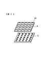
図2および図3は焦点検出光学系4と焦点検出センサー5の詳細を示す図である。図において、焦点検出光学系4は、複数のマイクロレンズ41を二次元状に配列したマイクロレンズアレイであり、撮影レンズ23のピントを合わせようとする面すなわち撮像素子2の撮像面と共役な面の近傍に配置される。なお、図2および図3ではマイクロレンズの数を少なく描いているが、実際のマイクロレンズは100ミクロンもしくはそれ以下のピッチで配列されるので、マイクロレンズアレイが例えば5mm角の広さであれば、マイクロレンズの数は非常に大きな数となる。
2 and 3 are diagrams showing details of the focus detection
焦点検出センサー5は、複数の受光素子(光電変換素子)51を二次元状に配列した受光素子アレイであり、焦点検出光学系(マイクロレンズアレイ)4の背後に配置される。なお、図3ではマイクロレンズごとに縦5個、横5個の合計25個の受光素子を正方配列にした受光素子アレイを例に上げて説明するが、マイクロレンズごとの受光素子の数はこの一実施の形態の数に限定されない。また、マイクロレンズごとに複数の受光素子をまとめて配置せずに、複数の受光素子を二次元状に配列した受光素子アレイとしてもよい。
The
被写体からの光束は、クイックリターンミラー9を透過しサブミラー10に反射され、焦点検出光学系(マイクロレンズアレイ)4を介して焦点検出センサー(受光素子アレイ)へ導かれる。
The light beam from the subject passes through the
図4(b)は焦点検出光学系4と焦点検出センサー5を撮影レンズ23側から見た図、図4(c)は焦点検出光学系4と焦点検出センサー5の横断面図である。焦点検出センサー5の各マイクロレンズ41に対応する25個の受光素子の中から、中央の1受光素子の出力を抽出してマイクロレンズアレイ(焦点検出光学系)4の並び通りに並べると、図4(a)に示すような二次元画像が得られる。図4(a)では被写体の目の部分の像が形成されている例を示す。なお、図4(c)では各マイクロレンズ41に対応する25個の受光素子の中の中央の1受光素子の受光する光束の広がりを図示する。
4B is a view of the focus detection
二次元画像を生成するためにマイクロレンズごとに抽出する受光素子出力としては、上述した中央の1受光素子出力に限らず、複数の受光素子出力を加算した値を用いてもよい。例えば縦3個、横3個の合計9個の受光素子の出力を加算した値を用いる。加算する受光素子数が多いほど、被写体が暗い場合の焦点検出能力を上げることができる。 The light receiving element output extracted for each microlens to generate a two-dimensional image is not limited to the above-described central one light receiving element output, and a value obtained by adding a plurality of light receiving element outputs may be used. For example, a value obtained by adding the outputs of a total of nine light receiving elements of three vertically and three horizontally is used. The greater the number of light receiving elements to be added, the higher the focus detection capability when the subject is dark.
《焦点検出演算回路6》
図5は焦点検出演算回路6の詳細な構成を示す図である。焦点検出演算回路6はA/Dコンバーター61、メモリ62、マイクロコンピューター63などを備え、マイクロコンピューター63のソフトウエア形態により二次元画像作成部64、特徴抽出部65、領域設定部66、画像信号抽出部67、像ずれ演算部68およびデフォーカス量演算部69を構成する。
<< Focus
FIG. 5 is a diagram showing a detailed configuration of the focus detection
焦点検出センサー(受光素子アレイ)5のすべての受光素子51の出力は、順次読み出されてA/Dコンバーター61によりデジタル信号に変換された後、メモリ62に記憶される。なお、詳細を後述するが、特定の焦点検出エリアが選択された場合には、選択された焦点検出エリアを中心とする所定範囲内の受光素子出力だけを読み出す。
The outputs of all the
《二次元画像作成部64》
二次元画像作成部64は、メモリ63に記憶されている焦点検出センサー5の受光素子出力の内の、特定の位置を中心とする所定範囲内のマイクロレンズ下の中央受光素子出力を並べて図4(a)に示すような二次元画像を作成する。
<< two-dimensional
The two-dimensional
図6(a)に示すように、撮影レンズ23の撮影画面100内には11カ所に焦点検出エリアが設定されており、上述した液晶表示器12はファインダースクリーン11上の被写体像に11カ所の焦点検出エリアの位置を表すマーク101を重畳して表示する。例えば撮影画面100内の右上の焦点検出エリアが選択されると、図6(b)に示すように選択された焦点検出エリアを中心とする所定の画像範囲が設定され、この画像範囲内のマイクロレンズ下の例えば中央受光素子出力を並べて二次元画像を作成する。図6(b)において、中央の黒点は焦点検出エリアの位置を表す。
As shown in FIG. 6A, eleven focus detection areas are set in the photographing
具体的には、図7(a)に示す被写体像の内の選択された右上の焦点検出エリアを中心とする所定の画像範囲(図7(b)参照)が設定され、この画像範囲内のマイクロレンズ下の中央受光素子出力を並べて図7(c)に示す二次元画像データを生成する。なお、この一実施の形態では、図6(b)および図7(c)に示す二次元画像の構成要素を“画素”と呼び、その輝度値をV[i,j](iは画素の行番号、jは画素の列番号)と表す。 Specifically, a predetermined image range (see FIG. 7B) centering on the selected focus detection area on the upper right in the subject image shown in FIG. 7A is set, and within this image range The two-dimensional image data shown in FIG. 7C is generated by arranging the central light receiving element outputs under the microlenses. In this embodiment, the components of the two-dimensional image shown in FIG. 6B and FIG. 7C are called “pixels”, and the luminance value is V [i, j] (i is the pixel value). The row number, j is the pixel column number).
《特徴抽出部65》
特徴抽出部65は、二次元画像作成部64で作成した二次元画像の第1方向(行方向)における画素どうしの輝度の差分すなわちコントラストを計算する。図8(a)は、図7(c)に示す二次元画像V[i,j]の横隣接画素のコントラストCh[i,j]を次式により求め、
Ch[i,j]=|V[i,j]−V[i+1,j]| ・・・(1)
図8(e)に示す4段階のコントラストレベルに分けて表したものである。この一実施の形態では、画素のコントラスト範囲を0〜255とし、所定値Cho(例えば30)以上のコントラストCh[i,j](≧Cho)を黒塗りで表す。図8(a)において、黒塗りの部分は図7(c)に示す二次元画像V[i,j]の“特徴点”である。なお、画像の特徴点の決定方法はこの一実施の形態の決定方法に限定されず、コントラストに関する量が検出できる方法であればよい。
<<
The
Ch [i, j] = | V [i, j] −V [i + 1, j] | (1)
This is divided into four contrast levels shown in FIG. 8 (e). In this embodiment, the contrast range of the pixels is set to 0 to 255, and a contrast Ch [i, j] (≧ Ch) that is equal to or greater than a predetermined value Cho (for example, 30) is represented by black. In FIG. 8A, the black portions are “feature points” of the two-dimensional image V [i, j] shown in FIG. Note that the method for determining the feature points of the image is not limited to the determination method of this embodiment, and any method that can detect the amount related to contrast may be used.
《領域設定部66》
領域設定部66は、図8(a)に示す黒塗りの特徴点の内、選択された焦点検出エリア位置(図中に黒点で示す)に近い1個(2個または3個でもよい)を選び、選択した特徴点を中心に焦点検出領域を設定する。図8(a)において黒点で示す焦点検出エリア位置に近い3個の特徴点(黒塗り画素)を中心に焦点検出領域を設定した例を図9(a)に示す。
<<
The
一般に、第1の方向すなわち横(行)方向に長い焦点検出領域を設定するのが望ましい。図9(a)に示す焦点検出領域では、第1方向(横方向)に沿って3個の特徴点が分布しており、したがってこの方向に沿って像ずれを検出するのが好ましい。なお、一般に第1方向に対し45度斜め方向までならコントラストの変化が大きく、したがって第1方向から45度斜め方向、あるいは0〜45度の中間方向を設定することも可能である。 In general, it is desirable to set a focus detection region that is long in the first direction, that is, the lateral (row) direction. In the focus detection area shown in FIG. 9A, three feature points are distributed along the first direction (lateral direction). Therefore, it is preferable to detect the image shift along this direction. In general, the change in contrast is large up to 45 ° oblique direction with respect to the first direction. Therefore, it is possible to set a 45 ° oblique direction from the first direction or an intermediate direction of 0 to 45 °.
図8(a)に示す例では黒点で示す特定の位置、ここでは選択した焦点検出エリア位置の近傍に特徴点が存在するが、図8(c)に示す例では特定の位置から少し離れた位置に特徴点があり、この場合には図9(c)に示すように焦点検出領域を設定する。以上の処理により、常にコントラストの高い部分を中心に焦点検出エリアを設定することが可能になる。 In the example shown in FIG. 8A, the feature point exists in the vicinity of the specific position indicated by the black dot, here the selected focus detection area position, but in the example shown in FIG. 8C, it is slightly apart from the specific position. There is a feature point at the position, and in this case, a focus detection area is set as shown in FIG. With the above processing, it is possible to always set the focus detection area around the high contrast portion.
被写体が縦縞構造である場合には上述した焦点検出領域の設定方法でよいが、横縞構造の場合にも最適な焦点検出領域を設定するために、特徴抽出部65および領域設定部66は、第1方向と同様な方法で第1方向と異なる第2方向において上述した特徴抽出処理と焦点検出領域設定処理を行う。ここで、第2方向は、第1方向から45度以上離れた方向が好ましく、多くは90度異なる方向とする。この一実施の形態では第2方向を縦方向(列方向)とする。
When the subject has a vertical stripe structure, the focus detection region setting method described above may be used. However, in order to set an optimum focus detection region even in the case of a horizontal stripe structure, the
特徴抽出部65は、二次元画像作成部64で作成した二次元画像の第2方向(縦方向)における画素どうしのコントラストを計算する。図8(b)は、図7(c)の二次元画像V[i,j]の縦隣接画素のコントラストCv[i,j]を次式により求め、
Cv[i,j]=|V[i,j]−V[i,j+1]| ・・・(2)
図8(e)に示す4段階のコントラストレベルに分けて表したものである。図8(b)において、黒塗りの部分はコントラストCv[i,j]が所定値Cvo=30以上の画素であり、図7(c)に示す二次元画像V[i,j]の“特徴点”である。
The
Cv [i, j] = | V [i, j] −V [i, j + 1] | (2)
This is divided into four contrast levels shown in FIG. 8 (e). In FIG. 8 (b), the black portions are pixels whose contrast Cv [i, j] is a predetermined value Cvo = 30 or more, and “features” of the two-dimensional image V [i, j] shown in FIG. Point ".
領域設定部66は、図8(b)に示す黒塗りの特徴点の内、選択された焦点検出エリア位置(図中に黒点で示す)に近い1個(2個または3個でもよい)を選び、選択した特徴点を中心に焦点検出領域を設定する。図8(b)において黒点で示す焦点検出エリア位置に近い3個の特徴点(黒塗り画素)を中心に焦点検出領域を設定した例を図9(b)に示す。
The
一般に、第2方向すなわち縦(列)方向に長い焦点検出領域を設定するのが望ましい。図9(b)に示す焦点検出領域では、第2方向(縦方向)に沿って7個の特徴点が分布しており、したがってこの方向に沿って像ずれを検出するのが好ましい。なお、一般に第2方向に対し45度斜め方向までならコントラストの変化が大きく、したがって第2方向から45度斜め方向、あるいは0〜45度の中間方向を設定することも可能である。 In general, it is desirable to set a focus detection region that is long in the second direction, that is, the vertical (column) direction. In the focus detection area shown in FIG. 9B, seven feature points are distributed along the second direction (longitudinal direction). Therefore, it is preferable to detect image shift along this direction. In general, the change in contrast is large if the direction is oblique to 45 degrees with respect to the second direction, and therefore, it is possible to set an oblique direction of 45 degrees from the second direction or an intermediate direction of 0 to 45 degrees.
図8(b)に示す例では黒点で示す特定の位置、ここでは選択した焦点検出エリア位置の近傍に特徴点が存在するが、図8(d)に示す例では特定の位置から少し離れた位置に特徴点があり、この場合には図9(d)に示すように焦点検出領域を設定する。以上の処理により、画像の第2方向(縦方向)においても常にコントラストの高い部分を中心に焦点検出エリアを設定することが可能になる。 In the example shown in FIG. 8B, the feature point exists in the vicinity of the specific position indicated by the black dot, here the selected focus detection area position, but in the example shown in FIG. 8D, it is slightly apart from the specific position. There is a feature point at the position, and in this case, a focus detection area is set as shown in FIG. With the above processing, it is possible to always set a focus detection area centering on a portion with high contrast even in the second direction (vertical direction) of the image.
なお、上述した特徴抽出部65と領域設定部66の処理では第1方向と第2方向に分けて特徴抽出と焦点検出領域設定を行う例を示したが、方向を分けずにコントラストを検出して特徴点を抽出し、特徴点を含むようにして複数の方向に焦点検出領域を設定するようにしてもよい。その場合の隣接画素のコントラストC[i,j]を次式により求める。
C[i,j]=|V[i,j]−V[i+1,j]|+|V[i,j]−V[i,j+1]| ・・・(3)
算出したコントラストC[i,j]を所定値Co(=30)と比較し、所定値Co以上の画素を特徴点とする。
In the above-described processing of the
C [i, j] = | V [i, j] −V [i + 1, j] | + | V [i, j] −V [i, j + 1] | (3)
The calculated contrast C [i, j] is compared with a predetermined value Co (= 30), and pixels having the predetermined value Co or more are used as feature points.
《画像信号抽出部67》
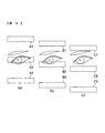
図10は、図9(a)に示す焦点検出領域を拡大した図である。像ずれ検出方向である焦点検出領域の長手方向の長さは、適宜決定する。図9(a)および図10は2列の画素列を焦点検出領域として選択した例を示すが、図11に示すように1列の画素列を焦点検出領域として選択してもよい。あるいは、3列以上の画素列を焦点検出領域として選択してもよい。焦点検出領域内のマイクロレンズに対応する複数の受光素子の出力信号に基づいて、撮影レンズ23の異なる瞳領域を通過した対の光束による像のずれ量を示す焦点検出信号、すなわち対の焦点検出用信号列を生成する。
<< Image
FIG. 10 is an enlarged view of the focus detection area shown in FIG. The length in the longitudinal direction of the focus detection area, which is the image shift detection direction, is appropriately determined. FIG. 9A and FIG. 10 show an example in which two pixel columns are selected as the focus detection region. However, as shown in FIG. 11, one pixel column may be selected as the focus detection region. Alternatively, three or more pixel columns may be selected as the focus detection area. Based on the output signals of a plurality of light receiving elements corresponding to the microlenses in the focus detection region, focus detection signals indicating the amount of image shift due to the pair of light beams that have passed through different pupil regions of the photographing
図10および図11において、マイクロレンズ下の黒塗りした受光素子の出力を焦点検出用の一対の信号列、第1信号列{a(i)}と第2信号列{b(i)}(i=1,2,3,・・)を抽出する。
第1信号列{a(i)}=a(1)、a(2)、a(3)、・・・、
第2信号列{b(i)}=b(1)、b(2)、b(3)、・・・ ・・・(4)
なお、図10に示す例では、各マイクロレンズ下の3個の受光素子出力を加算するとともに、2列の焦点検出画素列の上下2個の画素出力を加算して信号列を生成する。また、斜め45度方向に焦点検出領域を設定する場合には、図11に示すように焦点検出用画素を決定して信号列を生成する。
10 and 11, the output of the black light-receiving element under the microlens is converted into a pair of focus detection signal sequences, a first signal sequence {a (i)} and a second signal sequence {b (i)} ( i = 1, 2, 3,...
First signal sequence {a (i)} = a (1), a (2), a (3),.
Second signal sequence {b (i)} = b (1), b (2), b (3), ... (4)
In the example shown in FIG. 10, three light receiving element outputs under each microlens are added, and two upper and lower pixel outputs of two focus detection pixel rows are added to generate a signal row. Further, when the focus detection area is set in a 45-degree direction, a focus detection pixel is determined and a signal sequence is generated as shown in FIG.
《像ずれ演算部68》
像ずれ演算部68は、第1信号列{a(i)}と第2信号列{b(i)}を用いて周知の像ずれ演算を行い、デフォーカス量を算出する。まず、第1信号列{a(i)}と第2信号列{b(i)}から一対の像(信号列)の相関量C(N)を次式により求める。
C(N)=Σ|a(i)−b(j)| ・・・(5)
(5)式において、j−i=N(シフト数)、Σは上底がqL、下底がpLの総和演算を表す。
<< Image
The image
C (N) = Σ | a (i) −b (j) | (5)
In the equation (5), j−i = N (the number of shifts), and Σ represents a summation operation where the upper base is qL and the lower base is pL.
(5)式により得られた離散的な相関量C(N)からシフト量を求める。C(N)の中でシフト量Nのときに極小値を与える相関量をCoとし、シフト量(N−1)における相関量をCr、シフト量(N+1)における相関量をCfとする。これらの3個の相関量Cr、Co、Cfの並びから精密なシフト量Laを次式により求める。
DL=0.5×(Cr−Cf)、
E=max{Cf−Co、Cr−Co}、
Na=N+DL/E ・・・(6)
これに焦点検出面の位置に応じた補正量(定数const)を加え、焦点検出面上での像ずれ量Δnを算出する。
Δn=Na+const ・・・(7)
The shift amount is obtained from the discrete correlation amount C (N) obtained by the equation (5). Let C be the correlation amount that gives the minimum value when the shift amount is N in C (N), Cr be the correlation amount at the shift amount (N−1), and Cf be the correlation amount at the shift amount (N + 1). A precise shift amount La is obtained from the arrangement of these three correlation amounts Cr, Co, Cf by the following equation.
DL = 0.5 × (Cr−Cf),
E = max {Cf-Co, Cr-Co},
Na = N + DL / E (6)
A correction amount (constant const) corresponding to the position of the focus detection surface is added to this to calculate an image shift amount Δn on the focus detection surface.
Δn = Na + const (7)
《デフォーカス量演算部69》
デフォーカス量演算部69は、検出開角に依存する定数Kfを用いて次式により像ずれ量Δnからデフォーカス量Dfを算出する。
Df=Kf×Δn ・・・(8)
<< Defocus
The defocus
Df = Kf × Δn (8)
《被写体の動きに応じた焦点検出領域の設定方法》
次に、連続して複数回の焦点検出を行う場合に、被写体の動きに応じて最初に設定した焦点検出領域の被写体像が移動することがある。そのような場合に、最初の検出被写体部分と同一の部分を焦点検出領域として追い続ける方法を説明する。例えば、1回目の焦点検出において図12(a)に示す二次元画像が得られ、続く2回目の焦点検出で図12(b)に示す二次元画像が得られたとする。
<Setting method of focus detection area according to subject movement>
Next, when performing focus detection a plurality of times in succession, the subject image in the focus detection region initially set may move in accordance with the motion of the subject. In such a case, a method for continuing to follow the same portion as the first detected subject portion as the focus detection region will be described. For example, it is assumed that the two-dimensional image shown in FIG. 12A is obtained in the first focus detection and the two-dimensional image shown in FIG. 12B is obtained in the subsequent second focus detection.
被写体の動きを追う画像としては、画像自体V[i,j]の時刻t=t1における画像V1[i,j]と、時刻t=t2における画像V2[i,j]とを用いてもよいが、上述した第1方向(横方向)の隣接画素のコントラストCh[i,j]、もしくは第2方向(縦方向)の隣接画素のコントラストCv[i,j]、あるいは複数方向の隣接画素のコントラストC[i,j]を用いることができる。 As an image that follows the movement of the subject, an image V1 [i, j] at time t = t1 of the image itself V [i, j] and an image V2 [i, j] at time t = t2 may be used. Is the contrast Ch [i, j] of the adjacent pixel in the first direction (horizontal direction), or the contrast Cv [i, j] of the adjacent pixel in the second direction (vertical direction), or Contrast C [i, j] can be used.
ここでは、例えば複数方向の隣接画素のコントラストC[i,j]の時刻t=t1におけるコントラストC1[i,j]と、時刻t=t2におけるコントラストC2[i,j]とを用いる場合について説明する。すでに検出が終わっている画像C1[i,j]については、図8(a)と図8(b)とを加算したようなコントラスト分布が存在するので、これを活用して比較領域に設定する。領域は正方形の方が扱いやすいので、例えば図12(c)に示す7×6画素の枠で、上述した特定の位置に近い特徴点の内の少なくとも所定の個数を含むように範囲を決める。 Here, for example, the case where the contrast C1 [i, j] at time t = t1 and the contrast C2 [i, j] at time t = t2 of the contrast C [i, j] of adjacent pixels in a plurality of directions is used will be described. To do. For the image C1 [i, j] that has already been detected, there is a contrast distribution obtained by adding FIG. 8A and FIG. 8B, and this is used to set the comparison region. . Since the square is easier to handle, the range is determined so as to include at least a predetermined number of feature points close to the specific position described above, for example, in a 7 × 6 pixel frame shown in FIG.
領域の決め方は厳密である必要はないので、上述した所定個数の特徴点を含むように範囲を決める方法の他に、できるだけ多くの特徴点を含むように範囲を決める方法や、その他の方法でもよい。こうして決められたn×m画素の範囲{is1≦i1≦is1+n-1、js1≦j1≦js1+m-1}のコントラストC1[i,j]と、新しく時刻t=t2で検出された図12(d)に示すコントラストC2[i,j]からn×mの画素範囲{is2≦i2≦is2+n-1、js2≦j2≦js2+m-1}とを比較し、次式により相関量D[p,q]を求める。
D[p,q]=Σ|C1[i1,j1]−C2[i2,j2]|、
is2=is1+p、js2=js1+q、j2=i1+p、j2=j1+q ・・・(9)
(9)式における加算は{is1≦i1≦is1+n-1、js1≦i1≦js1+m-1}の範囲で行う。
The method of determining the region does not have to be exact, so in addition to the method of determining the range so as to include the predetermined number of feature points as described above, the method of determining the range to include as many feature points as possible or other methods Good. The contrast C1 [i, j] in the n × m pixel range {is1 ≦ i1 ≦ is1 + n−1, js1 ≦ j1 ≦ js1 + m−1} determined in this way and newly detected at time t = t2 The pixel range {is2 ≦ i2 ≦ is2 + n−1, js2 ≦ j2 ≦ js2 + m−1} from the contrast C2 [i, j] shown in FIG. A correlation amount D [p, q] is obtained.
D [p, q] = Σ | C1 [i1, j1] −C2 [i2, j2] |
is2 = is1 + p, js2 = js1 + q, j2 = i1 + p, j2 = j1 + q (9)
The addition in the equation (9) is performed in the range of {is1 ≦ i1 ≦ is1 + n−1, js1 ≦ i1 ≦ js1 + m−1}.
次に、[p,q]を変えて相関量D[p,q]の最小値を与える[p,q]を求める。相関量D[p,q]の最小値を与える[p,q]がズレの大きさと方向を表すベクトルである。このベクトル[p,q]だけずらした位置に焦点検出領域を設定する。図12(c)と(d)の場合は、[p,q]=[0,2]であるから、下の方に2画素だけずらした位置に新しい焦点検出領域を設定する。焦点検出領域設定後の処理は上述した処理と同様であり、説明を省略する。 Next, [p, q] is obtained by changing [p, q] to give the minimum value of the correlation amount D [p, q]. [P, q] giving the minimum value of the correlation amount D [p, q] is a vector representing the magnitude and direction of the deviation. A focus detection area is set at a position shifted by this vector [p, q]. In the case of FIGS. 12C and 12D, since [p, q] = [0,2], a new focus detection area is set at a position shifted by 2 pixels downward. The processing after setting the focus detection area is the same as the processing described above, and a description thereof will be omitted.
《精細に画像を抽出する方法》
図4では各マイクロレンズ下の1つの受光素子出力を抽出して二次元画像を作成する例を示したが、さらに精細な二次元画像を抽出する方法を説明する。図13(b)は、図4(c)と同じ焦点検出光学系(マイクロレンズアレイ)4と焦点検出センサー5の断面を示すが、マイクロレンズごとにマイクロレンズ中央近傍の横方向2受光素子、縦方向2受光素子の合計4受光素子出力を加算せずに取り出し、各マイクロレンズ下の4受光素子出力を並べて図13(a)に示す二次元画像を作成する。この場合、各マイクロレンズ下の4受光出力を、同じマイクロレンズに属する受光素子は並び順を逆転させて並べる。
《How to extract images in detail》
Although FIG. 4 shows an example in which one light receiving element output under each microlens is extracted to create a two-dimensional image, a method for extracting a more detailed two-dimensional image will be described. FIG. 13B shows a cross section of the same focus detection optical system (microlens array) 4 and focus
図13(c)において、焦点検出センサー(受光素子アレイ)5上では301a、301b、302a、302b、303a、303b、・・とすると、二次元画像合成面310上では301b、301a、302b、302a、303b、303a、・・の順で並ぶため、焦点検出センサー5上の並びを同じマイクロレンズに属する受光素子は並び順を逆転させて並べる。このようにして、図13(a)に示すような二次元画像を作成すれば、二次元画像合成面310近傍では高精細な画像が形成されるので、より精度の高い判断が可能になる。例えば各マイクロレンズから1受光素子出力を抽出する場合は図7(c)に示す画像となるが、各マイクロレンズから4受光素子出力を抽出すると、画像合成面310の近傍では図7(d)に示すような高精細な画像が得られる。
In FIG. 13C, if 301a, 301b, 302a, 302b, 303a, 303b,... On the focus detection sensor (light receiving element array) 5, 301b, 301a, 302b, 302a on the two-dimensional
このように、一実施の形態によれば、複数のマイクロレンズを二次元状に配列したマイクロレンズアレイと、マイクロレンズごとに複数の受光素子を有し、結像光学系からの光束をマイクロレンズを介して受光する受光素子アレイと、受光素子アレイの受光素子から出力される信号に基づいて画像情報と結像光学系の焦点調節状態を表す焦点検出信号を生成し、画像情報と焦点検出信号に基づいて結像光学系の焦点調節状態を検出するようにしたので、画像情報と焦点検出信号とに基づいて結像光学系の焦点検出を行うので、焦点検出位置として任意に選択可能な位置の中から適切に焦点検出位置を設定することができる。 As described above, according to one embodiment, a microlens array in which a plurality of microlenses are two-dimensionally arranged and a plurality of light receiving elements are provided for each microlens, and the light beam from the imaging optical system is microlens A light receiving element array that receives light via the light receiving element, and generates a focus detection signal that represents image information and a focus adjustment state of the imaging optical system based on a signal output from the light receiving element of the light receiving element array. Since the focus adjustment state of the imaging optical system is detected based on the image information, and the focus detection of the imaging optical system is performed based on the image information and the focus detection signal, the position can be arbitrarily selected as the focus detection position. The focus detection position can be set appropriately from among the above.
上述したように、焦点検出領域が密に配置されておらず、かつまた焦点検出領域の幅が狭い焦点検出装置では、ピントを合わせたい被写体のコントラストの高い部分を焦点検出領域で捕捉することが困難であった。この一実施の形態では、マイクロレンズアレイと受光素子アレイを用いて結像光学系の焦点検出を行うので、結像光学系の撮影画面内の任意の位置を焦点検出領域として設定可能であり、焦点検出領域設定の自由度が高いという利点がある。しかし、自由度が高いゆえにピントを合わせたい位置に適切に焦点検出領域を設定することがより重要な課題となるが、このような操作を撮影者が手動で行うのは煩雑である。そこで、この一実施の形態ではさらに、受光素子アレイの受光出力から焦点検出信号の他に画像情報すなわち二次元画像データを取得し、画像情報と焦点検出信号とに基づいて焦点検出を行う構成を備え、受光素子アレイの受光出力を利用して簡単な構成で適切に焦点検出領域の選択を可能にし、ピントを合わせたい被写体の内のコントラストの高い部分を焦点検出領域で捕捉して高精度な焦点検出を実現する。 As described above, in the focus detection device in which the focus detection areas are not densely arranged and the width of the focus detection area is narrow, a high-contrast portion of the subject to be focused can be captured in the focus detection area. It was difficult. In this embodiment, since the focus detection of the imaging optical system is performed using the microlens array and the light receiving element array, an arbitrary position in the imaging screen of the imaging optical system can be set as the focus detection region. There is an advantage that the degree of freedom in setting the focus detection area is high. However, since the degree of freedom is high, it is more important to appropriately set a focus detection area at a position where focus is desired. However, it is complicated for a photographer to manually perform such an operation. Therefore, in this embodiment, in addition to the focus detection signal, image information, that is, two-dimensional image data, is acquired from the light reception output of the light receiving element array, and focus detection is performed based on the image information and the focus detection signal. It is possible to select the focus detection area appropriately with a simple configuration using the light receiving output of the light receiving element array, and capture the high-contrast part of the subject to be focused in the focus detection area with high accuracy. Realize focus detection.
一実施の形態によれば、画像情報から特徴を検出し、特徴が検出された位置に相当する画面内の位置に焦点検出領域を設定するようにしたものである。例えば、画像情報のコントラストを検出し、コントラストが所定値以上となる部分の位置に焦点検出領域を設定する。これにより、ピントを合わせたい被写体の内のコントラストの高い部分に焦点検出領域を設定することができ、高精度な焦点検出を実現する。 According to one embodiment, a feature is detected from image information, and a focus detection region is set at a position in the screen corresponding to the position where the feature is detected. For example, the contrast of the image information is detected, and the focus detection area is set at the position where the contrast is a predetermined value or more. As a result, the focus detection area can be set in a high-contrast portion of the subject to be focused, and high-precision focus detection is realized.
1 カメラボディ
4 焦点検出光学系(マイクロレンズアレイ)
5 焦点検出センサー(受光素子アレイ)
6 焦点検出演算回路
23 撮影レンズ
1
5 Focus detection sensor (light receiving element array)
6 Focus
Claims (8)
前記マイクロレンズごとに複数の受光素子を有し、光像を形成する結像光学系からの光束を前記マイクロレンズを介して前記複数の受光素子が受光する受光素子アレイと、
前記複数の受光素子の出力信号に基づいて前記光像に関する画像情報を生成する画像情報生成手段と、
前記画像情報に基づいて、前記結像光学系の焦点調節状態を検出する焦点検出領域を設定する領域設定手段と、
前記焦点検出領域に位置する前記マイクロレンズに対応する前記複数の受光素子の出力信号に基づいて、前記焦点調節状態を検出する焦点検出手段と、を備え、
前記焦点検出手段は、前記結像光学系の異なる瞳領域を通過した対の光束によって形成される対の前記光像のずれ量に基づいて、前記焦点調節状態を検出することを特徴とする焦点検出装置。 A microlens array in which a plurality of microlenses are arranged two-dimensionally;
A plurality of light receiving elements for each microlens, and a light receiving element array in which the plurality of light receiving elements receive a light beam from an imaging optical system that forms an optical image via the microlens;
Image information generating means for generating image information relating to the optical image based on output signals of the plurality of light receiving elements;
An area setting means for setting a focus detection area for detecting a focus adjustment state of the imaging optical system based on the image information;
Focus detection means for detecting the focus adjustment state based on output signals of the plurality of light receiving elements corresponding to the microlenses located in the focus detection region,
The focus detection unit detects the focus adjustment state based on a shift amount of the pair of optical images formed by a pair of light beams that have passed through different pupil regions of the imaging optical system. Detection device.
前記画像情報生成手段は、予め設定された焦点検出位置を含む所定領域からの前記出力信号に基づいて、前記画像情報を生成することを特徴とする焦点検出装置。 The focus detection apparatus according to claim 1,
The focus detection apparatus characterized in that the image information generation means generates the image information based on the output signal from a predetermined area including a preset focus detection position.
前記領域設定手段は、前記画像情報として前記光像のコントラスト情報を検出し、前記コントラストが所定値以上となる領域を含んで前記焦点検出領域を設定することを特徴とする焦点検出装置。 The focus detection apparatus according to claim 2,
The area detection unit detects contrast information of the optical image as the image information, and sets the focus detection area including an area where the contrast is a predetermined value or more.
前記領域設定手段は、前記受光素子アレイ上の第1方向の前記コントラストを検出するとともに、前記第1方向と異なる第2方向における前記コントラストを検出することを特徴とする焦点検出装置。 The focus detection apparatus according to claim 3,
The focus detection apparatus, wherein the region setting means detects the contrast in a first direction on the light receiving element array and detects the contrast in a second direction different from the first direction.
前記領域設定手段は、第1時刻に前記コントラストを検出して前記焦点検出領域を設定した後の第2時刻において、前記第1時刻に検出した前記コントラストと同じコントラストが含まれるように前記焦点検出領域を設定することを特徴とする焦点検出装置。 The focus detection apparatus according to any one of claims 3 and 4,
The region setting means detects the focus so that the same contrast as the contrast detected at the first time is included at a second time after detecting the contrast at the first time and setting the focus detection region. A focus detection apparatus that sets an area.
前記画像情報生成手段は、前記各マイクロレンズに対応する前記複数の受光素子から得られる出力信号を選択して前記画像情報を生成することを特徴とする焦点検出装置。 In the focus detection apparatus according to any one of claims 1 to 5,
The focus detection apparatus, wherein the image information generation unit generates the image information by selecting output signals obtained from the plurality of light receiving elements corresponding to the microlenses.
前記画像情報生成手段は、前記マイクロレンズごとの前記複数の受光素子のうちの前記マイクロレンズ下の中央の受光素子からの前記出力信号を選択して、前記画像情報を生成することを特徴とする焦点検出装置。 The focus detection apparatus according to claim 6,
The image information generating unit selects the output signal from a central light receiving element below the micro lens among the plurality of light receiving elements for each micro lens, and generates the image information. Focus detection device .
Priority Applications (3)
| Application Number | Priority Date | Filing Date | Title |
|---|---|---|---|
| JP2007047526A JP5034556B2 (en) | 2007-02-27 | 2007-02-27 | Focus detection apparatus and imaging apparatus |
| US12/038,731 US7805067B2 (en) | 2007-02-27 | 2008-02-27 | Focus detection device for image forming optical system, imaging apparatus, and focus detection method for image forming optical system |
| EP08102085.1A EP1972980B1 (en) | 2007-02-27 | 2008-02-27 | Focus detection device for image forming optical system, imaging apparatus, and focus detection method for image forming optical system |
Applications Claiming Priority (1)
| Application Number | Priority Date | Filing Date | Title |
|---|---|---|---|
| JP2007047526A JP5034556B2 (en) | 2007-02-27 | 2007-02-27 | Focus detection apparatus and imaging apparatus |
Publications (3)
| Publication Number | Publication Date |
|---|---|
| JP2008209762A JP2008209762A (en) | 2008-09-11 |
| JP2008209762A5 JP2008209762A5 (en) | 2011-03-10 |
| JP5034556B2 true JP5034556B2 (en) | 2012-09-26 |
Family
ID=39415106
Family Applications (1)
| Application Number | Title | Priority Date | Filing Date |
|---|---|---|---|
| JP2007047526A Expired - Fee Related JP5034556B2 (en) | 2007-02-27 | 2007-02-27 | Focus detection apparatus and imaging apparatus |
Country Status (3)
| Country | Link |
|---|---|
| US (1) | US7805067B2 (en) |
| EP (1) | EP1972980B1 (en) |
| JP (1) | JP5034556B2 (en) |
Families Citing this family (38)
| Publication number | Priority date | Publication date | Assignee | Title |
|---|---|---|---|---|
| US10298834B2 (en) | 2006-12-01 | 2019-05-21 | Google Llc | Video refocusing |
| JP5061858B2 (en) * | 2007-11-12 | 2012-10-31 | 株式会社ニコン | Focus detection apparatus and imaging apparatus |
| JP5247298B2 (en) | 2008-08-18 | 2013-07-24 | サーパス工業株式会社 | Suck back valve |
| JP2010085922A (en) * | 2008-10-02 | 2010-04-15 | Nikon Corp | Focus detector and imaging device |
| JP2010109921A (en) * | 2008-10-31 | 2010-05-13 | Nikon Corp | Image synthesizing apparatus |
| JP5217942B2 (en) * | 2008-11-18 | 2013-06-19 | 株式会社ニコン | Focus adjustment device and imaging device |
| WO2010077625A1 (en) * | 2008-12-08 | 2010-07-08 | Refocus Imaging, Inc. | Light field data acquisition devices, and methods of using and manufacturing same |
| US8570427B2 (en) * | 2009-01-28 | 2013-10-29 | Nikon Corporation | Image-capturing device having focus adjustment function, image creation method including focus adjustment function, and program product for image-capturing device having focus adjustment function |
| JP5402298B2 (en) * | 2009-06-23 | 2014-01-29 | 株式会社ニコン | Focus detection device and camera |
| RU2608690C2 (en) * | 2010-07-16 | 2017-01-23 | Филипс Лайтинг Холдинг Б.В. | Light projector and vision system for distance determination |
| JP5825817B2 (en) * | 2011-04-01 | 2015-12-02 | キヤノン株式会社 | Solid-state imaging device and imaging apparatus |
| CN103212823B (en) * | 2012-01-19 | 2016-08-31 | 昆山思拓机器有限公司 | The focus searching method of Photoelectric Jiao's device |
| JP5932363B2 (en) * | 2012-01-26 | 2016-06-08 | キヤノン株式会社 | Imaging apparatus and control method thereof |
| US9858649B2 (en) | 2015-09-30 | 2018-01-02 | Lytro, Inc. | Depth-based image blurring |
| JP6045280B2 (en) * | 2012-10-09 | 2016-12-14 | オリンパス株式会社 | Imaging device |
| US10334151B2 (en) | 2013-04-22 | 2019-06-25 | Google Llc | Phase detection autofocus using subaperture images |
| US20150185308A1 (en) * | 2014-01-02 | 2015-07-02 | Katsuhiro Wada | Image processing apparatus and image processing method, image pickup apparatus and control method thereof, and program |
| US10540818B2 (en) | 2015-04-15 | 2020-01-21 | Google Llc | Stereo image generation and interactive playback |
| US10341632B2 (en) | 2015-04-15 | 2019-07-02 | Google Llc. | Spatial random access enabled video system with a three-dimensional viewing volume |
| US10419737B2 (en) | 2015-04-15 | 2019-09-17 | Google Llc | Data structures and delivery methods for expediting virtual reality playback |
| US10469873B2 (en) | 2015-04-15 | 2019-11-05 | Google Llc | Encoding and decoding virtual reality video |
| US10546424B2 (en) | 2015-04-15 | 2020-01-28 | Google Llc | Layered content delivery for virtual and augmented reality experiences |
| US10444931B2 (en) | 2017-05-09 | 2019-10-15 | Google Llc | Vantage generation and interactive playback |
| US10412373B2 (en) | 2015-04-15 | 2019-09-10 | Google Llc | Image capture for virtual reality displays |
| US10567464B2 (en) | 2015-04-15 | 2020-02-18 | Google Llc | Video compression with adaptive view-dependent lighting removal |
| US10275898B1 (en) | 2015-04-15 | 2019-04-30 | Google Llc | Wedge-based light-field video capture |
| US10565734B2 (en) | 2015-04-15 | 2020-02-18 | Google Llc | Video capture, processing, calibration, computational fiber artifact removal, and light-field pipeline |
| US10440407B2 (en) | 2017-05-09 | 2019-10-08 | Google Llc | Adaptive control for immersive experience delivery |
| US11328446B2 (en) | 2015-04-15 | 2022-05-10 | Google Llc | Combining light-field data with active depth data for depth map generation |
| US9979909B2 (en) | 2015-07-24 | 2018-05-22 | Lytro, Inc. | Automatic lens flare detection and correction for light-field images |
| US10275892B2 (en) | 2016-06-09 | 2019-04-30 | Google Llc | Multi-view scene segmentation and propagation |
| US10679361B2 (en) | 2016-12-05 | 2020-06-09 | Google Llc | Multi-view rotoscope contour propagation |
| US10594945B2 (en) | 2017-04-03 | 2020-03-17 | Google Llc | Generating dolly zoom effect using light field image data |
| US10474227B2 (en) | 2017-05-09 | 2019-11-12 | Google Llc | Generation of virtual reality with 6 degrees of freedom from limited viewer data |
| US10354399B2 (en) | 2017-05-25 | 2019-07-16 | Google Llc | Multi-view back-projection to a light-field |
| EP3441812B1 (en) * | 2017-08-11 | 2020-07-01 | Tecan Trading Ag | Pattern based autofocus method for a microscopy |
| US10545215B2 (en) | 2017-09-13 | 2020-01-28 | Google Llc | 4D camera tracking and optical stabilization |
| US10965862B2 (en) | 2018-01-18 | 2021-03-30 | Google Llc | Multi-camera navigation interface |
Family Cites Families (21)
| Publication number | Priority date | Publication date | Assignee | Title |
|---|---|---|---|---|
| JPS57108810A (en) * | 1980-12-26 | 1982-07-07 | Nippon Kogaku Kk <Nikon> | Focus detector |
| US4410804A (en) * | 1981-07-13 | 1983-10-18 | Honeywell Inc. | Two dimensional image panel with range measurement capability |
| JPS5887512A (en) | 1981-11-19 | 1983-05-25 | Nippon Kogaku Kk <Nikon> | Focus detecting device |
| JPS58211721A (en) * | 1982-06-04 | 1983-12-09 | Olympus Optical Co Ltd | Focusing detecting method |
| US4561749A (en) * | 1983-02-02 | 1985-12-31 | Nippon Kogaku K.K. | Focus detection apparatus |
| JPS59160109A (en) | 1983-03-03 | 1984-09-10 | Nippon Kogaku Kk <Nikon> | Detector for light image |
| JPS59146008A (en) * | 1983-02-10 | 1984-08-21 | Olympus Optical Co Ltd | Focusing detector |
| JPS59208515A (en) | 1983-05-12 | 1984-11-26 | Minolta Camera Co Ltd | Focus detecting device |
| US4766302A (en) * | 1984-05-17 | 1988-08-23 | Minolta Camera Kabushiki Kaisha | Focus detecting device including means for determining a priority of correlation calculations |
| JPH0772762B2 (en) * | 1985-10-30 | 1995-08-02 | ミノルタ株式会社 | Focus detection device |
| US5422701A (en) * | 1990-01-30 | 1995-06-06 | Nikon Corporation | Focus detection apparatus |
| JPH06153067A (en) * | 1992-10-30 | 1994-05-31 | Fuji Photo Film Co Ltd | Video camera and its photometric method |
| JPH07199052A (en) | 1993-12-28 | 1995-08-04 | Olympus Optical Co Ltd | Focus detecting method and distance measuring method |
| JPH1096852A (en) | 1996-09-20 | 1998-04-14 | Kyocera Corp | Focus detector using two-dimensional imaging device |
| US6819360B1 (en) * | 1999-04-01 | 2004-11-16 | Olympus Corporation | Image pickup element and apparatus for focusing |
| JP2001330769A (en) | 2000-05-24 | 2001-11-30 | Canon Inc | Image pickup device and its control method |
| JP4686853B2 (en) | 2000-12-07 | 2011-05-25 | 株式会社ニコン | Manufacturing method of re-imaging lens |
| US6895181B2 (en) * | 2002-08-27 | 2005-05-17 | Olympus Corporation | Camera and distance measuring method thereof |
| WO2006129677A1 (en) * | 2005-05-30 | 2006-12-07 | Nikon Corporation | Image formation state detection device |
| JP4788481B2 (en) * | 2005-05-30 | 2011-10-05 | 株式会社ニコン | Imaging state detection device, camera, and light receiving unit |
| JP4578334B2 (en) * | 2005-06-22 | 2010-11-10 | 富士フイルム株式会社 | In-focus position determining apparatus and method for imaging lens |
-
2007
- 2007-02-27 JP JP2007047526A patent/JP5034556B2/en not_active Expired - Fee Related
-
2008
- 2008-02-27 US US12/038,731 patent/US7805067B2/en not_active Expired - Fee Related
- 2008-02-27 EP EP08102085.1A patent/EP1972980B1/en not_active Expired - Fee Related
Also Published As
| Publication number | Publication date |
|---|---|
| US20080205871A1 (en) | 2008-08-28 |
| EP1972980B1 (en) | 2019-04-10 |
| US7805067B2 (en) | 2010-09-28 |
| EP1972980A1 (en) | 2008-09-24 |
| JP2008209762A (en) | 2008-09-11 |
Similar Documents
| Publication | Publication Date | Title |
|---|---|---|
| JP5034556B2 (en) | Focus detection apparatus and imaging apparatus | |
| JP5191168B2 (en) | Focus detection apparatus and imaging apparatus | |
| JP5195506B2 (en) | Imaging apparatus and image composition method | |
| US8259215B2 (en) | Image pickup apparatus having focus control using phase difference detection | |
| US6377305B2 (en) | Image sensing apparatus | |
| JP4766133B2 (en) | Imaging device | |
| WO2010001641A1 (en) | Focal point detection device | |
| JP4692654B2 (en) | Imaging apparatus and image processing program | |
| JP6045214B2 (en) | Focus adjustment apparatus and control method thereof | |
| JP5617157B2 (en) | Focus detection apparatus and imaging apparatus | |
| JP4995002B2 (en) | Imaging device, focusing device, imaging method, and focusing method | |
| JP2011097645A (en) | Image synthesizing apparatus, imaging apparatus, and image synthesizing method | |
| JP5402298B2 (en) | Focus detection device and camera | |
| JP5380857B2 (en) | Focus detection apparatus and imaging apparatus | |
| JP5446311B2 (en) | Imaging device | |
| JP2010177860A (en) | Image composition apparatus, imaging apparatus, and image composition method | |
| JP6561437B2 (en) | Focus adjustment device and imaging device | |
| JP5240591B2 (en) | Imaging device, focusing device, imaging method, and focusing method | |
| JP2012083584A (en) | Imaging device | |
| JP5966299B2 (en) | FOCUS DETECTION DEVICE AND IMAGING DEVICE HAVING THE SAME | |
| JP2009063689A (en) | Focus detecting device and imaging apparatus | |
| JP2013122494A (en) | Focus detector and camera | |
| JP2006023653A (en) | Optical equipment | |
| JP2013122495A (en) | Focus detector and camera | |
| US8553133B2 (en) | Focusing apparatus |
Legal Events
| Date | Code | Title | Description |
|---|---|---|---|
| A621 | Written request for application examination |
Free format text: JAPANESE INTERMEDIATE CODE: A621 Effective date: 20100121 |
|
| A521 | Request for written amendment filed |
Free format text: JAPANESE INTERMEDIATE CODE: A523 Effective date: 20100608 |
|
| RD02 | Notification of acceptance of power of attorney |
Free format text: JAPANESE INTERMEDIATE CODE: A7422 Effective date: 20100608 |
|
| A521 | Request for written amendment filed |
Free format text: JAPANESE INTERMEDIATE CODE: A523 Effective date: 20110121 |
|
| A131 | Notification of reasons for refusal |
Free format text: JAPANESE INTERMEDIATE CODE: A131 Effective date: 20120124 |
|
| A521 | Request for written amendment filed |
Free format text: JAPANESE INTERMEDIATE CODE: A523 Effective date: 20120322 |
|
| TRDD | Decision of grant or rejection written | ||
| A01 | Written decision to grant a patent or to grant a registration (utility model) |
Free format text: JAPANESE INTERMEDIATE CODE: A01 Effective date: 20120605 |
|
| A01 | Written decision to grant a patent or to grant a registration (utility model) |
Free format text: JAPANESE INTERMEDIATE CODE: A01 |
|
| A61 | First payment of annual fees (during grant procedure) |
Free format text: JAPANESE INTERMEDIATE CODE: A61 Effective date: 20120618 |
|
| FPAY | Renewal fee payment (event date is renewal date of database) |
Free format text: PAYMENT UNTIL: 20150713 Year of fee payment: 3 |
|
| R150 | Certificate of patent or registration of utility model |
Ref document number: 5034556 Country of ref document: JP Free format text: JAPANESE INTERMEDIATE CODE: R150 Free format text: JAPANESE INTERMEDIATE CODE: R150 |
|
| FPAY | Renewal fee payment (event date is renewal date of database) |
Free format text: PAYMENT UNTIL: 20150713 Year of fee payment: 3 |
|
| R250 | Receipt of annual fees |
Free format text: JAPANESE INTERMEDIATE CODE: R250 |
|
| R250 | Receipt of annual fees |
Free format text: JAPANESE INTERMEDIATE CODE: R250 |
|
| R250 | Receipt of annual fees |
Free format text: JAPANESE INTERMEDIATE CODE: R250 |
|
| R250 | Receipt of annual fees |
Free format text: JAPANESE INTERMEDIATE CODE: R250 |
|
| R250 | Receipt of annual fees |
Free format text: JAPANESE INTERMEDIATE CODE: R250 |
|
| R250 | Receipt of annual fees |
Free format text: JAPANESE INTERMEDIATE CODE: R250 |
|
| LAPS | Cancellation because of no payment of annual fees |