JP6239418B2 - Air diffuser and cleaning method - Google Patents
Air diffuser and cleaning method Download PDFInfo
- Publication number
- JP6239418B2 JP6239418B2 JP2014062076A JP2014062076A JP6239418B2 JP 6239418 B2 JP6239418 B2 JP 6239418B2 JP 2014062076 A JP2014062076 A JP 2014062076A JP 2014062076 A JP2014062076 A JP 2014062076A JP 6239418 B2 JP6239418 B2 JP 6239418B2
- Authority
- JP
- Japan
- Prior art keywords
- air
- diffuser
- valve
- pipe
- seconds
- Prior art date
- Legal status (The legal status is an assumption and is not a legal conclusion. Google has not performed a legal analysis and makes no representation as to the accuracy of the status listed.)
- Active
Links
- 238000004140 cleaning Methods 0.000 title claims description 64
- 238000000034 method Methods 0.000 title claims description 30
- 239000007788 liquid Substances 0.000 claims description 92
- 239000012528 membrane Substances 0.000 claims description 67
- 239000007787 solid Substances 0.000 claims description 31
- 238000005273 aeration Methods 0.000 claims description 25
- 238000005406 washing Methods 0.000 claims description 16
- 238000009792 diffusion process Methods 0.000 claims description 9
- 230000004043 responsiveness Effects 0.000 claims description 9
- 238000007599 discharging Methods 0.000 claims description 3
- 230000004044 response Effects 0.000 description 60
- XLYOFNOQVPJJNP-UHFFFAOYSA-N water Substances O XLYOFNOQVPJJNP-UHFFFAOYSA-N 0.000 description 58
- 238000005374 membrane filtration Methods 0.000 description 13
- 238000000926 separation method Methods 0.000 description 12
- 239000000706 filtrate Substances 0.000 description 10
- 230000000694 effects Effects 0.000 description 6
- 230000000630 rising effect Effects 0.000 description 5
- 238000001914 filtration Methods 0.000 description 4
- 230000010349 pulsation Effects 0.000 description 4
- 238000009736 wetting Methods 0.000 description 4
- 230000005484 gravity Effects 0.000 description 3
- 230000001151 other effect Effects 0.000 description 3
- 239000010865 sewage Substances 0.000 description 3
- 239000007858 starting material Substances 0.000 description 3
- 230000008859 change Effects 0.000 description 2
- 238000010586 diagram Methods 0.000 description 2
- 230000003628 erosive effect Effects 0.000 description 2
- 238000007654 immersion Methods 0.000 description 2
- 230000004048 modification Effects 0.000 description 2
- 238000012986 modification Methods 0.000 description 2
- 239000010802 sludge Substances 0.000 description 2
- 239000011343 solid material Substances 0.000 description 2
- 239000002351 wastewater Substances 0.000 description 2
- 229910000831 Steel Inorganic materials 0.000 description 1
- BZHJMEDXRYGGRV-UHFFFAOYSA-N Vinyl chloride Chemical compound ClC=C BZHJMEDXRYGGRV-UHFFFAOYSA-N 0.000 description 1
- 230000001133 acceleration Effects 0.000 description 1
- 230000002411 adverse Effects 0.000 description 1
- 238000004378 air conditioning Methods 0.000 description 1
- 238000005452 bending Methods 0.000 description 1
- 230000000903 blocking effect Effects 0.000 description 1
- 230000001112 coagulating effect Effects 0.000 description 1
- 238000005260 corrosion Methods 0.000 description 1
- 230000007797 corrosion Effects 0.000 description 1
- 230000007423 decrease Effects 0.000 description 1
- 239000010840 domestic wastewater Substances 0.000 description 1
- 238000001035 drying Methods 0.000 description 1
- 239000012530 fluid Substances 0.000 description 1
- 239000010800 human waste Substances 0.000 description 1
- 230000007246 mechanism Effects 0.000 description 1
- 244000005700 microbiome Species 0.000 description 1
- 230000008569 process Effects 0.000 description 1
- 230000009467 reduction Effects 0.000 description 1
- 239000011347 resin Substances 0.000 description 1
- 229920005989 resin Polymers 0.000 description 1
- 239000010959 steel Substances 0.000 description 1
- 239000000126 substance Substances 0.000 description 1
- 210000003437 trachea Anatomy 0.000 description 1
- 238000011144 upstream manufacturing Methods 0.000 description 1
- 238000004065 wastewater treatment Methods 0.000 description 1
Images


Classifications
-
- Y—GENERAL TAGGING OF NEW TECHNOLOGICAL DEVELOPMENTS; GENERAL TAGGING OF CROSS-SECTIONAL TECHNOLOGIES SPANNING OVER SEVERAL SECTIONS OF THE IPC; TECHNICAL SUBJECTS COVERED BY FORMER USPC CROSS-REFERENCE ART COLLECTIONS [XRACs] AND DIGESTS
- Y02—TECHNOLOGIES OR APPLICATIONS FOR MITIGATION OR ADAPTATION AGAINST CLIMATE CHANGE
- Y02W—CLIMATE CHANGE MITIGATION TECHNOLOGIES RELATED TO WASTEWATER TREATMENT OR WASTE MANAGEMENT
- Y02W10/00—Technologies for wastewater treatment
- Y02W10/10—Biological treatment of water, waste water, or sewage
Landscapes
- Aeration Devices For Treatment Of Activated Polluted Sludge (AREA)
- Accessories For Mixers (AREA)
- Separation Using Semi-Permeable Membranes (AREA)
Description
本発明は、例えば、固液分離を行う浸漬型膜分離装置の膜エレメントを洗浄曝気するための散気装置及びその洗浄方法に関する。 The present invention relates to an air diffuser for cleaning and aeration of a membrane element of an immersion type membrane separator that performs solid-liquid separation, for example, and a cleaning method thereof.
固液分離を行う浸漬型膜分離装置(メンブレンバイオリアクター(Membrane Bioreactor: MBR))は、下水、し尿、生活排水、工場廃水などの汚水を好気的に生物分解させる有機性廃水の活性汚泥法による排水処理において、膜エレメントによる固液分離を行う技術として知られている。
この浸漬型膜分離装置は、例えば、複数の膜エレメントを膜面を鉛直に並列して縦に積層した状態で固定して構成される膜ユニットを開放式の反応槽内に配置し、各膜エレメントに濾過液を取り出すための配管を接続し、この配管に吸引ポンプを設けて濾過液を処理水槽へ送るように構成されている。
The submerged membrane separator (Membrane Bioreactor (MBR)) that performs solid-liquid separation is an activated sludge process for organic wastewater that aerobically biodegrades sewage such as sewage, human waste, domestic wastewater, and factory wastewater. It is known as a technique for performing solid-liquid separation by a membrane element in wastewater treatment by the above.
This submerged membrane separation apparatus, for example, arranges a membrane unit configured by fixing a plurality of membrane elements in a state where membrane surfaces are vertically stacked in parallel with each other in an open type reaction tank, A pipe for taking out the filtrate is connected to the element, and a suction pump is provided in the pipe to send the filtrate to the treated water tank.
反応槽には、原水供給ポンプによって被処理液を供給する原水供給配管が配設されている。各膜エレメントの直下には、散気装置として管に複数の空気噴出口を設けた散気管が膜面に直交方向に配設されている。これにより、各膜エレメントの間に上昇する気泡を均等に供給できるようになっている。散気管にはブロワを設けた空気供給配管が接続されている。空気供給配管はブロワの近傍に逆止弁を設けている。 The reaction tank is provided with raw water supply piping for supplying the liquid to be treated by the raw water supply pump. Immediately below each membrane element, an air diffuser provided with a plurality of air outlets in the tube as an air diffuser is disposed in a direction orthogonal to the membrane surface. Thereby, the air bubbles rising between the membrane elements can be supplied uniformly. An air supply pipe provided with a blower is connected to the air diffuser. The air supply pipe is provided with a check valve in the vicinity of the blower.
この浸漬型膜分離装置では、被処理液を原水供給ポンプにより継続的に反応槽に供給し、ブロワの駆動により散気管の空気噴出口から空気を噴出させる。この噴出気流により、膜エレメントの膜面間を気泡に同伴させて被処理液の上昇流を発生させながら、好気性微生物への曝気をしながら槽内被処理液を膜ユニットの無いところで下降流にして槽内を旋回させる。それと共に、吸引ポンプの間歇的駆動により膜エレメントの膜の内側の濾板に設けられる濾過液通路側を間歇的に減圧する。膜エレメントの濾過液側の減圧と反応槽の水位による浸漬型膜エレメントへの加圧水圧とによる膜間差圧のもとで汚水を膜濾過させる。濾過液は、配管を介して吸引ポンプの下流側にある処理水槽に送られ貯えられる。
また、この浸漬型膜分離装置では、ブロワの駆動により散気管の空気噴出口から噴出した空気の上昇によって生じる気液混合の上向流によって膜エレメントの膜面を洗浄し、濾過を行いつつも被処理液中の固形分による膜面への汚泥層の付着を抑制することで安定した濾過運転を行っている。
In this submerged membrane separation apparatus, the liquid to be treated is continuously supplied to the reaction tank by the raw water supply pump, and air is ejected from the air outlet of the air diffuser by driving the blower. This jet air flow causes bubbles between the membrane surfaces of the membrane element to generate an upward flow of the liquid to be processed, while aeration of the aerobic microorganisms is performed while the liquid to be processed in the tank flows downward without the membrane unit. Rotate the tank. At the same time, the filtrate passage side provided in the filter plate inside the membrane of the membrane element is intermittently decompressed by intermittent driving of the suction pump. The sewage is subjected to membrane filtration under a transmembrane pressure difference caused by a reduced pressure on the filtrate side of the membrane element and a pressurized water pressure applied to the submerged membrane element due to the water level in the reaction vessel. The filtrate is sent to and stored in a treated water tank on the downstream side of the suction pump via a pipe.
Further, in this submerged membrane separation apparatus, the membrane surface of the membrane element is washed and filtered by the upward flow of gas-liquid mixing caused by the rise of air ejected from the air outlet of the diffuser tube by driving the blower. Stable filtration operation is performed by suppressing the adhesion of the sludge layer to the membrane surface due to the solid content in the liquid to be treated.
しかし、この浸漬型膜分離装置では、空気が噴出する空気噴出口から反応槽内の被処理液が浸入し、被処理液中の固形分が空気噴出口を塞いだり、空気によって乾燥された固形物が空気噴出口の内側に凝固して覆ったりすると噴出する空気の減少やムラが発生して膜面洗浄不良となり、安定した濾過運転ができない。
このため、定期的に散気管の洗浄が必要となる。従来の散気管洗浄では、例えば、ブロワを駆動しながら、又はブロワを停止させて、空気供給配管の途中から水又は洗浄液を空気の流れと同方向となるように流す方法が知られている。しかし、この方法では、被処理液が乾燥、凝固した固形物は、水や水を含んだ液で濡らしただけで気流と同じ方向へ液を流しただけでは簡単に洗浄できない。加えて、洗浄操作中は、空気噴出口から被処理液と同等の比重を持つ液体のみが噴出することとなり、膜エレメントに被処理水の上昇流は生じることができず膜面に被処理水が届かないので、膜濾過を停止しなければならない。
また、散気管を水槽から引き上げて、洗浄を行う方法が知られている。しかし、この方法では、洗浄操作中は、膜エレメントに被処理水が届かないことに加え、膜面の洗浄は同時に行われないので、当然膜濾過を停止しなければならない。
However, in this submerged membrane separation apparatus, the liquid to be processed in the reaction tank enters from the air outlet from which air is ejected, and solids in the liquid to be processed block the air outlet and are dried by air. If an object solidifies and covers the inside of the air outlet, the air that is ejected is reduced or uneven, resulting in poor film surface cleaning, and a stable filtration operation is not possible.
For this reason, it is necessary to periodically clean the air diffuser. In conventional air diffuser cleaning, for example, a method is known in which a blower is driven or the blower is stopped, and water or a cleaning liquid is caused to flow in the same direction as the air flow from the middle of the air supply pipe. However, in this method, the solid material obtained by drying and coagulating the liquid to be treated cannot be easily washed by simply flowing the liquid in the same direction as the air flow just by being wet with water or a liquid containing water. In addition, during the cleaning operation, only the liquid having the same specific gravity as the liquid to be treated is ejected from the air outlet, and the upward flow of the water to be treated cannot be generated in the membrane element, and the water to be treated is formed on the membrane surface. Since it does not reach, membrane filtration must be stopped.
In addition, a method is known in which the air diffuser is lifted from the water tank and washed. However, in this method, during the cleaning operation, in addition to the fact that the water to be treated does not reach the membrane element, the membrane surface is not cleaned at the same time, so the membrane filtration must naturally be stopped.
そこで、散気管内の洗浄方法として、被処理液を空気噴出口から逆流(反応槽側から散気管内に)させて、空気噴出口廻りの固形物を湿潤させたり、剥離させたりして噴出する空気の減少やムラを解消することが行われている。
例えば、散気開始時に散気管内に流入している固形物を排出するために、散気管の先端を下方に屈曲させ、且つその先端に空気噴出口より大きな開口を設けた散気管を用いることが提案されている(例えば、特許文献1参照)。そして、特許文献1では、散気管は空気供給管を通してブロワに接続している。空気供給管はブロワの吐出口の近傍に逆止弁を設け、管路頂部に開閉弁を介して分岐ノズルを設けている。
Therefore, as a method of cleaning the inside of the air diffuser, the liquid to be treated is caused to flow backward from the air outlet (from the reaction tank side into the air diffuser), and the solid matter around the air outlet is wetted or peeled off. The reduction of air and unevenness are being eliminated.
For example, in order to discharge the solid matter flowing into the diffuser at the start of the diffuser, use a diffuser with the tip of the diffuser bent downward and having an opening larger than the air outlet at the tip. Has been proposed (see, for example, Patent Document 1). And in
また、特許文献1は、散気管の洗浄時に、ブロワを停止し、開閉弁を開けることで散気管内部の圧力を下げ、水圧によって被処理液を空気噴出口より散気管内に流入している。
特許文献1によれば、散気管内の圧力を瞬時に大気圧まで低下させることで、散気管内への被処理液の逆流入を円滑に行うことができる。
In
According to
また、散気管の先端側に散気ドレン管を接続し、この散気ドレン管のドレンバルブを開放し、散気管に供給する空気を散気ドレン管を通して排出し、空気噴出口から散気管内に被処理液を逆流入させて散気管内を洗浄する技術が提案されている(例えば、特許文献2参照)。
また、特許文献2は、配管内の圧力変化によって生じる脈動を利用して断続的に水洗浄を繰り返すことを開示している。
Also, a diffuser drain pipe is connected to the tip side of the diffuser pipe, the drain valve of this diffuser drain pipe is opened, the air supplied to the diffuser pipe is discharged through the diffuser drain pipe, and the inside of the diffuser pipe is discharged from the air outlet. A technique has been proposed in which the liquid to be treated is caused to flow backward to clean the inside of the air diffuser (see, for example, Patent Document 2).
Moreover,
しかし、特許文献1では、ブロワを停止しても、ブロワモータへの電源OFFをしたところで高速で動作していたインペラはすぐには停止せず、慣性で動き続けるので、風量も静圧も徐々に低下していく。また、空気供給配管に逆止弁が設けられていても、ブロワ停止直後に逆止弁の上流配管内に圧力が残っていると、なかなか逆止弁が閉止せず、散気管内への被処理水の逆流はゆっくりと行われる。
また、ブロワを一旦停止して再び駆動するには、ブロワモータの高出力から、スターデルタ起動回路など直入れ起動以外の起動回路での起動時に、過度の電圧が電気回路に掛からないよう、ブロワのインペラが完全に停止し、且つ電気回路の切り替え後に起動しなければならず、一旦ブロワを停止すると、再駆動には一定時間が必要である。
また、ブロワを一定時間停止することから空気供給配管は大気圧まで結局低下するので、散気管内を瞬時に大気圧まで下げるため、空気供給配管の管路頂部に設けた開閉弁を開く必要があり、空気供給配管の反応槽の立上り管のほぼ反応槽の被処理液位近くまで被処理水が登ってくることとなる。そのため、特許文献1では、散気管洗浄時には膜濾過運転を停止する必要があった。
However, in
In order to stop the blower and drive it again, the blower motor must be operated so that an excessive voltage is not applied to the electric circuit when starting from a high output of the blower motor, using a starter circuit other than the direct input starter such as a star delta starter circuit. The impeller must be completely stopped and must be started after the electrical circuit is switched. Once the blower is stopped, a certain time is required for re-driving.
In addition, since the blower is stopped for a certain period of time, the air supply pipe will eventually drop to atmospheric pressure, so it is necessary to open the on-off valve provided at the top of the air supply pipe in order to instantaneously reduce the inside of the diffuser pipe to atmospheric pressure. Yes, the water to be treated climbs to the level of the liquid to be treated in the riser of the reaction tank of the air supply pipe. Therefore, in
一方、特許文献2では、ブロワを運転したまま洗浄できるが、膜ユニットへの散気が行われないため、洗浄操作中は、空気噴出口から被処理液と同等の比重を持つ液体のみが噴出することとなり、膜エレメントに被処理水の上昇流は生じることができず膜面に被処理水が届かないので、膜濾過を停止する必要がある。継続的に反応槽に流入してくる原水を適正に処理するには、洗浄する膜ユニット分が全体の膜ユニットから除外されても処理できるよう、予め洗浄切り離し分を足して設備しておかなければならず、イニシャルコストが増大する。また、それぞれの膜ユニットごとに、散気管先端側に散気ドレン管を追加する必要がありさらにコスト増大となる。
On the other hand, in
本発明は斯かる従来の問題点を解決するために為されたもので、その目的は、散気管の圧力を瞬間的に大気圧下へ開放することで、膜濾過運転を止めることなく散気管の洗浄が可能な散気装置及び洗浄方法を提供することにある。 The present invention has been made in order to solve such a conventional problem, and an object of the present invention is to instantaneously release the pressure of the air diffuser to the atmospheric pressure, so that the air diffuser can be operated without stopping the membrane filtration operation. Another object of the present invention is to provide an air diffuser and a cleaning method capable of cleaning.
本発明に係る散気装置は、浸漬型膜分離装置に用いられる散気装置であって、反応槽内に浸漬され、前記浸漬型膜分離装置の下方に略水平に設置され前記反応槽の底面側に複数の空気噴出口を設ける散気管と、前記散気管に先端を接続され基端部を反応槽液位から外部空気中に延設される空気供給配管と、前記空気供給配管の基端部に接続され、散気運転時及び散気管洗浄時に駆動されるブロワと、前記空気供給配管の前記反応槽液位から外部空気中の途中に分岐配管を介して接続され、前記散気管の洗浄時に開放される開閉弁とを備え、前記開閉弁が、応答性の異なる二つのバルブで構成され、開動作と閉動作とで動作する順序を切り替えるよう構成されている。 An air diffuser according to the present invention is an air diffuser used in a submerged membrane separation device, which is immersed in a reaction tank, and is installed substantially horizontally below the submerged membrane separator, and is a bottom surface of the reaction tank. A diffuser pipe having a plurality of air jets on the side, an air supply pipe having a distal end connected to the diffuser pipe and having a proximal end extending from the reaction tank liquid level into the external air, and a proximal end of the air supply pipe A blower that is connected to the unit and is driven during the diffuser operation and when the diffuser pipe is cleaned, and is connected via a branch pipe in the middle of the external air from the liquid level of the reaction tank of the air supply pipe to clean the diffuser pipe and a opening and closing valve which is opened during the opening and closing valve is constituted by response of two different valves, that is configured to switch the order in which to operate in the opening operation and the closing operation.
本発明に係る散気装置は、前記散気管が、前記反応槽の底面側に複数の空気噴出口を設けた直管と、前記直管の管端に接続され、前記反応槽の底面側に開口するエルボ部とで構成されている。
本発明に係る散気装置は、前記開閉弁の動作が、制御装置に備わるタイマーに設定された時間で開閉を繰り返すよう構成されている。
In the air diffuser according to the present invention, the air diffuser is connected to a straight pipe provided with a plurality of air jets on the bottom side of the reaction tank, and to a pipe end of the straight pipe, and on the bottom side of the reaction tank It consists of an elbow that opens.
The air diffuser according to the present invention is configured so that the operation of the on-off valve repeats opening and closing at a time set in a timer provided in the control device .
本発明に係る散気装置は、前記空気供給配管が、前記ブロアの吐出部側から前記散気管に向けて順に順に逆止弁、空気フィルタ、風量計及び前記分岐配管を介して前記開閉弁を設けている。
本発明に係る散気装置の洗浄方法は、前記ブロワを運転しながら前記開閉弁を0.2秒間から10秒間の何れかの時間開放する操作を繰り返す。
In the air diffuser according to the present invention, the air supply pipe is connected to the open / close valve via the check pipe, the air filter, the air flow meter, and the branch pipe in order from the discharge part side of the blower toward the air diffuser pipe. Provided.
In the method of cleaning an air diffuser according to the present invention, the operation of opening the on-off valve for any time from 0.2 seconds to 10 seconds is repeated while operating the blower.
本発明に係る散気装置の洗浄方法は、前記ブロワを運転しながら前記開閉弁を0.2秒間から10秒間の何れかの時間開放し、前記散気管内の圧力を減少させ、前記反応槽内の被処理液を前記エルボ部の開口及び前記複数の空気噴出口から逆流入させ、散気時に前記複数の空気噴出口を逆流し散気管内部に凝固した固形物を湿潤させ、且つ前記散気管内を前記ブロワ側へ固形物を引き剥がして移動させ、前記散気管に逆流入した前記被処理液を、前記空気供給配管の反応槽の被処理液位から所定距離まで逆流入させる工程と、前記ブロワを運転しながら前記開閉弁を0.2秒間から10秒間の何れかの時間閉止し、前記複数の空気噴出口からの前記被処理液を排出させて洗浄する工程とを繰り返す。 In the method for cleaning an air diffuser according to the present invention, the on-off valve is opened for any time from 0.2 seconds to 10 seconds while the blower is operated, the pressure in the air diffuser is reduced, and the reaction vessel The liquid to be treated is allowed to flow backward from the opening of the elbow part and the plurality of air jets, and the solids solidified inside the air diffuser by wetting the plurality of air jets back during the aeration. A step of separating and moving the solid material to the blower side in the trachea, and causing the liquid to be treated to flow backward into the air diffuser to flow backward from the liquid level in the reaction tank of the air supply pipe to a predetermined distance; The operation of closing the on-off valve for any time from 0.2 seconds to 10 seconds while operating the blower, and discharging and cleaning the liquid to be processed from the plurality of air jets is repeated.
本発明に係る散気装置の洗浄方法は、前記開閉弁の開閉操作時間は0.2秒〜10秒間、前記開閉弁の操作間隔は0.5秒〜15秒間、前記開閉弁の操作回数は3回〜15回とする。
本発明に係る散気装置の洗浄方法は、前記開閉弁の開閉操作時間は0.2秒〜3秒間、前記開閉弁の操作間隔は0.5秒〜10秒間、前記開閉弁の操作回数は3回〜10回とする。
本発明に係る散気装置の洗浄方法は、前記空気噴出口廻りの固形物を湿潤化及び剥離させる際の管内流速は2.4m/s以上である。
本発明に係る散気装置の洗浄方法は、前記被処理液を前記散気管を介して前記空気供給配管へ逆流入させる前記供給配管の反応槽の被処理液位からの距離Δh’を、2.4m以上反応槽液高以下とする。
In the method of cleaning an air diffuser according to the present invention, the opening / closing operation time of the opening / closing valve is 0.2 seconds to 10 seconds, the operation interval of the opening / closing valve is 0.5 seconds to 15 seconds, and the number of operations of the opening / closing valve is 3 to 15 times.
In the method for cleaning an air diffuser according to the present invention, the opening / closing operation time of the opening / closing valve is 0.2 seconds to 3 seconds, the operation interval of the opening / closing valve is 0.5 seconds to 10 seconds, and the number of times the opening / closing valve is operated is 3 to 10 times.
In the method for cleaning an air diffuser according to the present invention, the flow velocity in the pipe when the solid matter around the air outlet is wetted and peeled is 2.4 m / s or more.
In the method for cleaning an air diffuser according to the present invention, a distance Δh ′ from the liquid level of the reaction tank in the reaction tank of the supply pipe for allowing the liquid to be treated to flow back into the air supply pipe via the air diffuser is set to 2 The reaction tank liquid height is 4 m or more.
本発明によれば、散気管の圧力を瞬間的に大気圧下へ開放し、その後散気管の圧力を上げることで、散気管に対する被処理液の流入、排出が行われ、この操作を複数回繰り返すことで散気管の洗浄を確実に行うことができる。
本発明によれば、散気管の大気圧下への開放は一瞬であり、膜濾過運転を止めることなく散気管の洗浄ができる。
本発明によれば、複数の空気噴出口の位置を散気管の中心より下方とすることで、大気圧下へ開放した際、散気管内の空気が抜けやすく、被処理液の流入、排出が効果的に行われ、より洗浄効果を高めることができる。
According to the present invention, the pressure of the air diffuser is instantaneously released to atmospheric pressure, and then the pressure of the air diffuser is increased, so that the liquid to be treated is introduced into and discharged from the air diffuser. By repeating, the air diffuser can be reliably cleaned.
According to the present invention, the opening of the diffuser tube to atmospheric pressure is instantaneous, and the diffuser tube can be cleaned without stopping the membrane filtration operation.
According to the present invention, by setting the positions of the plurality of air outlets below the center of the air diffuser, when the air diffuser is opened to atmospheric pressure, the air in the air diffuser can easily escape and the inflow and exhaust of the liquid to be processed can be prevented. It is carried out effectively and the cleaning effect can be further enhanced.
本発明によれば、口径の異なる2種類の空気噴出口を持つ散気管を用いるので、散気管内の剥離した固形物を口径の大きい空気噴出口より排出することができる。そのため、剥離した固形物による再閉塞が起こりにくい。
本発明によれば、被処理液の流入方向と散気空気の噴出方向が真逆のため、大気圧下開放の操作を繰り返すことで散気管内の固形物が2方向へ動き、洗浄効果が高い。
本発明によれば、膜濾過を行いながら散気管洗浄できる。
According to the present invention, since the air diffuser having two types of air jets having different diameters is used, the separated solid matter in the air diffuser can be discharged from the air jet having a large diameter. Therefore, re-occlusion due to the separated solid matter is unlikely to occur.
According to the present invention, since the inflow direction of the liquid to be treated and the ejection direction of the diffused air are exactly opposite, the solid matter in the diffuser pipe moves in two directions by repeating the opening operation under atmospheric pressure, and the cleaning effect is improved. high.
According to the present invention, it is possible to clean the air diffuser while performing membrane filtration.
本発明によれば、瞬間的に大気圧下へ開放することで固形物を剥離するが、すぐ元の散気状態へ戻すと剥離した固形物で空気噴出口を塞いでしまうので、散気状態を緩やかに戻すことで再閉塞を防止できる。
本発明によれば、開閉弁の開閉を繰り返すだけであるから、洗浄操作が簡潔である。
According to the present invention, the solid matter is peeled off by instantaneously releasing it to the atmospheric pressure, but if the air diffuser is immediately returned to the original diffused state, the air jet outlet is blocked by the peeled solid matter. Re-occlusion can be prevented by slowly returning
According to the present invention, the opening / closing valve is simply opened and closed repeatedly, so that the cleaning operation is simple.
以下、本発明の実施形態を図面に基づいて説明する。
図1、図2は、本発明の第一実施形態に係る散気装置10を示す。
なお、図1は、固液分離を行う浸漬型膜分離装置(MBR)に本実施形態に係る散気装置10を適用した例を示す。
Hereinafter, embodiments of the present invention will be described with reference to the drawings.
1 and 2 show an
FIG. 1 shows an example in which the
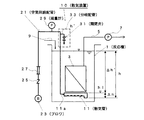
本実施形態に係る散気装置10は、例えば、固液分離を行う浸漬型膜分離装置(MBR)の複数の膜エレメント(図示せず)で構成される膜ユニット3を内部に配置した開放式の反応槽1において、膜ユニット3の直下に各膜エレメント(図示せず)を洗浄曝気するための散気管11を配設している。散気管11は、例えば、膜ユニット3の真下に設けた散気ユニット(図示せず)内に配置されている。
The
膜ユニット3は、濾過液を取り出すための配管5を各膜エレメント(図示せず)に接続されている。配管5は、吸引ポンプ7を設け、濾過液を処理水槽へ送るように構成されている。
反応槽1には、原水供給ポンプ(図示せず)によって被処理液を供給する原水供給配管9が配設されている。
In the
The
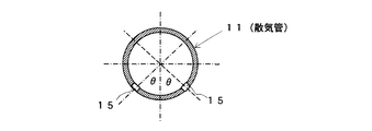
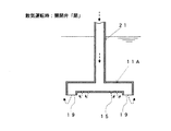
散気管11は、例えば、図2に示すように、複数の小口径(例えば、3mm〜5mm)の散気孔15を設けた直管13と、この直管13の末端をエルボ返しして下方へ向け、管端を大口径の散気孔19とするエルボ部17とで構成されている。大口径の散気孔19は、小口径の散気孔15よりも下方に位置している。
For example, as shown in FIG. 2, the
散気管11は、例えば、図2、図3に示すように、小口径の散気孔15を管下部に設けている。散気管11は、沈降する固形物で小口径の散気孔15が閉塞されにくくするため、例えば、図4に示すように、最下端部に設けず、最下端部から左右の側壁に向かって所定角度θずらして開設しても良い。
For example, as shown in FIGS. 2 and 3, the
散気管11の管端11aには、ブロワ23を設けた空気供給配管21が接続されている。空気供給配管21は、ブロワ23の吐出部側から散気管11に向けて順に逆止弁25、空気フィルタ27、風量計29及び、開閉弁31を管端又は途中に有する分岐配管33を設けている。開閉弁31は、大気開放可能で閉止時に漏れが少ないボール弁、バタフライ弁、仕切り弁などの弁で構成されている。
An
次に、本実施形態に係る散気装置10の作用を説明する。
図1に示す固液分離を行う浸漬型膜分離装置(MBR)では、原水供給ポンプ(図示せず)によって被処理液を原水供給配管9を介して反応槽1に供給する。
散気管運転時には、逆止弁25を開、開閉弁31を閉として、ブロワ23の駆動により空気供給配管21を介して散気管11へ空気を供給する。散気管11では、図5に示すように、小口径の散気孔15及び大口径の散気孔19から空気を噴出させ、この噴出気流により槽内被処理液を旋回させる。
Next, the operation of the
In the submerged membrane separator (MBR) that performs solid-liquid separation shown in FIG. 1, the liquid to be treated is supplied to the
During the operation of the air diffuser, the
同時に、吸引ポンプ7の間歇的駆動により複数の膜エレメントの濾過液通路側を間歇的に減圧し、各膜エレメントの濾過液側の減圧と反応槽1の水位による各膜エレメントへの加圧水圧とによる膜間差圧の元で水を膜濾過させる。膜により所定の固体を分離された濾過液は、配管5を介して処理水槽に貯えられる。
この散気管運転時に、空気が噴出する小口径の散気孔15から槽内の被処理液が浸入し、被処理液中の固形分が小口径の散気孔15を塞いでしまったり、空気によって乾燥され小口径の散気孔15の内側を固形物が覆ってしまったりして噴出する空気の減少やムラが発生する。
At the same time, the filtrate passage side of the plurality of membrane elements is intermittently depressurized by intermittent driving of the
During the operation of the air diffuser, the liquid to be treated in the tank enters from the
そこで、本実施形態では、ブロワ23を運転しながら開閉弁31を図示しないタイマー回路を備えた制御装置により、設定された時間での開閉を繰り返す。試験的には手動で開閉を繰り返してもかまわない。その際の開閉操作時間は、0.2秒〜10秒程度、好ましくは0.2秒〜3秒程度(開閉弁31の開放側は極力瞬時開放を目指し、弁の全閉から全開への開放時間能の最大近くで動作させるのが好ましい。)、操作間隔は、0.5秒〜10秒間程度、操作回数は、3回〜10回程度とする。
開閉弁31の操作による膜ユニット3への散気停止時間は、上記のように10秒以下なので、膜面における上昇流が完全に途切れることがないため、散気管11の洗浄時に濾過運転を停止することなく実施できる。
Therefore, in this embodiment, the opening / closing valve 31 is repeatedly opened and closed at a set time by a control device including a timer circuit (not shown) while the blower 23 is operated. For testing purposes, it may be opened and closed manually. The opening / closing operation time at that time is about 0.2 seconds to 10 seconds, preferably about 0.2 seconds to 3 seconds (the opening side of the opening / closing valve 31 is aimed at instantaneous opening as much as possible, and the valve is opened from fully closed to fully opened) It is preferable to operate near the maximum time capability.) The operation interval is about 0.5 to 10 seconds, and the number of operations is about 3 to 10 times.
Since the time for stopping the aeration to the
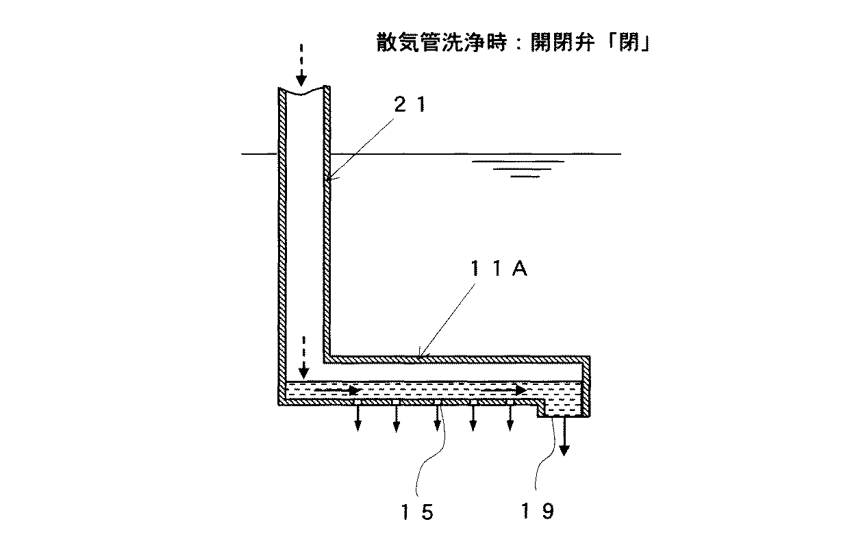
開閉弁31を開放すると、図6に示すように、散気管11内の圧力が減少し、大口径の散気孔19及び小口径の空気噴出口15から反応槽1内の被処理液が流入し、乾燥しかけた固形物を湿潤させ、且つ散気管11内をブロワ23側へ固形物を引き剥がして移動させて除去することができる。
大口径の散気孔19は、小口径の散気孔15よりも下方に位置するので、大口径の散気孔19からの大水量の被処理液の流入と小口径の散気孔15からの被処理液の流入とが直交して洗浄が行われる。
開閉弁31を閉止すると、図7に示すように、散気管11内の被処理液を大口径の散気孔19から吹き出すこととなり、散気管11を洗浄し、散気管11内の被処理液つまりを解消することができる。
When the on-off valve 31 is opened, as shown in FIG. 6, the pressure in the
Since the large-
When the on-off valve 31 is closed, as shown in FIG. 7, the liquid to be treated in the
次に、本実施形態に係る散気装置10の洗浄機構について詳述する。
先ず、本実施形態に係る散気装置10にて散気を行う場合のブロワ23の必要吐出圧力Pt(kPa)について説明する。
Pt=h+Hf+Hp+Hm+Hd+a
h:水深による水頭(ヘッド)による水圧(kPa)
Hf:空気フィルタ27の通過損失(kPa)
Hp:空気供給配管21の圧力損失(kPa)
Hm:風量計29の通過損失(kPa)
Hd:散気管11などの通過損失(kPa)
a:余裕圧(kPa)
Next, the cleaning mechanism of the
First, the required discharge pressure Pt (kPa) of the blower 23 when air is diffused by the
Pt = h + Hf + Hp + Hm + Hd + a
h: Water pressure (kPa) due to water head due to water depth
Hf:
Hp: Pressure loss of the air supply pipe 21 (kPa)
Hm: Passage loss of the air flow meter 29 (kPa)
Hd: Loss of passage through diffusing tube 11 (kPa)
a: Margin pressure (kPa)
ここで、反応槽1の水深を4.5mとした場合、水圧hは44.1kPaとなる。
通常、空気フィルタ27の通過損失Hf=0.2kPa、風量計29の通過損失Hm=0.5kPa、散気管11などの通過損失Hd=2kPa(粗気泡性散気管として)、余裕圧a=5kPa程度を見込むものとする。
空気供給配管21の圧力損失Hpは、配管口径、配管長、空気流速などの影響を受ける。
ブロワ23の必要吐出圧力Ptにおいて水圧hの占める割合が一番大きい。
Here, when the water depth of the
Usually, the passage loss Hf = 0.2 kPa of the
The pressure loss Hp of the
The ratio of the water pressure h in the required discharge pressure Pt of the blower 23 is the largest.
1)空気供給配管21の直管部の圧力損失Hpl(kPa)は、次式の通りとなる。
Hpl=1,267×10-2×273/T×4・f・L/D・V2/2g
L:管長(m)
D:管径(m)
f:係数(0.004〜0.059)
V:管内流速(m/s)
V=4Q/60πD2
g:重力加速度(9.8m/s2)
Q:風量(m3/min)
T:絶対温度(K)
1) The pressure loss Hpl (kPa) of the straight pipe portion of the
Hpl = 1,267 × 10 −2 × 273 / T × 4 · f · L / D · V 2 / 2g
L: Tube length (m)
D: Pipe diameter (m)
f: Coefficient (0.004 to 0.059)
V: Pipe flow velocity (m / s)
V = 4Q / 60πD 2
g: Gravity acceleration (9.8 m / s 2 )
Q: Air volume (m 3 / min)
T: Absolute temperature (K)
2)空気供給配管21の異形管部の圧力損失(90度曲管、T字管、管入口部などにおける圧力損失)Hp2(kPa)は、次式の通りとなる。
Hp2=K・V2/2g×l.267×10-2
V:管内流速(m/s)
K:各異形管部の圧力損失係数
2) The pressure loss (pressure loss at the 90-degree bent pipe, T-shaped pipe, pipe inlet, etc.) Hp2 (kPa) of the deformed pipe portion of the
Hp2 = K · V 2 / 2g × l. 267 × 10 -2
V: Pipe flow velocity (m / s)
K: Pressure loss coefficient of each deformed pipe
空気供給配管21の圧力損失Hpは、空気流速(管内流速)Vの二乗及び配管長さに比例し、配管径に反比例する。通常、散気に供する空気供給配管21における経済的な管内流速は、10m/s以下(4m/s〜8m/s程度)であり、この場合の空気供給配管21の圧力損失HpはlkPa以下と小さい。
散気管11に被処理液を逆流させるには、ブロワ23の吐出圧力より散気管11などの通過損失Hd、余裕圧a及び散気管11の上部から空気噴出口(小口径の散気孔15及び大口径の散気孔19)までの高さ分の水圧差Δhを減じれば良い。つまり、(Hd+a+△h)の圧力が減じれば散気空気は、hl迄しか押し込めず、水圧により散気管11内には被処理液が流入する。
hl=Pt−(Hd+a+△h)
The pressure loss Hp of the
In order to allow the liquid to be treated to flow back to the
hl = Pt− (Hd + a + Δh)
空気供給配管21から分岐した分岐配管33に設けた開閉弁31を開ければ、全風量(散気空気)がこの分岐配管33より流出しようとする。空気供給配管21と同口径であれば分岐配管33の管内流速も空気供給配管21と同じであり、分岐配管33の配管圧力損失Hpもごく小さい。つまり、hlにかかる圧力よりも分岐配管33にて放散される圧力が小さければ、水圧hにより散気管11内に被処理液が逆流する。その差が大きければ瞬時に散気管11内に被処理液が流入する。
また、被処理液が散気管11内に流入する場合に、空気噴出口が流入時の抵抗となるが、膜洗浄用の散気の場合、粗気泡が有利なため、空気噴出口が大きいので被処理液の流入の抵抗が小さい。
If the on-off valve 31 provided in the branch pipe 33 branched from the
In addition, when the liquid to be treated flows into the
hl=Pt−(Hd+a+△h)>Pt−(h+Hd+a)+h’
h−△h>h’
分岐配管33の口径を空気供給配管21の口部より小さくした場合、風量(散気量)は変わらず分岐配管33より全量流出すると、分岐配管33における管内流速が大きくなるため、二乗に比例して空気供給配管21の圧力損失Hpが大きくなる。この分岐配管33の圧力損失h’が、h−△hよりも小さくなければならない。
hl = Pt− (Hd + a + Δh)> Pt− (h + Hd + a) + h ′
h−Δh> h ′
When the diameter of the branch pipe 33 is made smaller than that of the
反応槽1の水深や分岐配管33の配管状態により差はあるが、分岐配管33における管内流速が50m/s以下であれば、通常の膜分離装置の散気装置を考えれば分岐配管33の圧力損失h’は十分h−△hよりも小さくなり、開閉弁31を開けることにより散気管11内に被処理液が瞬時に逆流できる。
空気供給配管21の管内流速と分岐配管33における管内流速が50m/s時の空気供給配管21との断面積比と口径比との関係を表1に示す。
Although there are differences depending on the water depth of the
Table 1 shows the relationship between the cross-sectional area ratio and the aperture ratio of the
散気管11は、下部に2mm〜10mm(本実施形態では4mm〜5mm)の空気噴出口(小口径の散気孔15)があり、散気管11の先端が下方に屈曲し開放されて大きな空気噴出口(大口径の散気孔19)を形成している。
開閉弁31が開となり、散気管11に繋がる空気供給管21内の圧力が低下し、散気管11には水圧hがかかる。
The
The on-off valve 31 is opened, the pressure in the
散気管11内を流れる流体(液体)の経済的な管内流速は1m/s〜2m/s程度となる。散気管11内に逆流し、空気噴出口(小口径の散気孔15)廻りの固形物を湿潤化及び剥離させるのに2.4m/s以上(例えば、3m/s)必要とする。被処理液は、各空気噴出口(小口径の散気孔15及び大口径の散気孔19)から流入するが、先端が下方に屈曲し開放された空気噴出口(大口径の散気孔19)から被処理液が流入しやすい。大口径の散気孔19の開放部が散気管11と同口径で抵抗が最も小さいためである。
An economical in-pipe flow velocity of the fluid (liquid) flowing through the
例えば、図5に示すように、図1に示す散気管11を口径を13A(13mm)とし、空気が2.5m/sで流入するものとし、仮にポンプ23が押し込こむとすると、必要揚程は大凡1m(9.8kPa)程度となる。
なお、図6は、散気管洗浄時に開閉弁31を開にした状態を示し、図7は、散気管洗浄時に開閉弁31を閉にした状態を示す。
For example, as shown in FIG. 5, if the diffusing
FIG. 6 shows a state in which the on-off valve 31 is opened at the time of cleaning the air diffuser, and FIG. 7 shows a state in which the on-off valve 31 is closed at the time of cleaning the air diffuser.
十分水深(水圧)があれば、例えば、図6に示すように、短時間(0.5m進むのに0.2秒)で散気管11を被処理液で満たすことができる。そのため、短時間で開閉弁31を開け閉めすることで、散気管11内に被処理液が流出入し、この脈動によって散気管11内の空気噴出口(小口径の散気孔15)廻りの固形物を湿潤化及び剥離し、除去できる。
また、短時間での開閉弁31の操作のため、膜洗浄用空気の途切れが最小限に抑えられ、膜の閉塞に影響が無く、膜濾過運転を行いながら散気管11の洗浄が可能となる。
If there is a sufficient water depth (water pressure), for example, as shown in FIG. 6, the
Further, since the on-off valve 31 is operated in a short period of time, interruption of the membrane cleaning air is minimized, there is no effect on the membrane clogging, and the
散気管11の直管13の損失水頭Hl1をダーシーの式より求めると、下記の通りとなる。
Hl1=fl+L/D×V2/2g
fl=0.02+0.0005/D
L:管長(m)
V:管内流速(m/s)
D:管内径(m)
When the head loss Hl 1 straight pipe 13 of the
Hl 1 = f 1 + L / D × V 2 / 2g
f l = 0.02 + 0.0005 / D
L: Tube length (m)
V: Pipe flow velocity (m / s)
D: Inner diameter of pipe (m)
その他の配管要素の損失水頭Hl2は、下記の通りとなる。
Hl2=f×V2/2g
f:各種配管要素の損失係数
V:管内流速(m/s)
※曲管の損失係数r/d=1、90度で0.3/ヶ
The loss head Hl 2 of other piping elements is as follows.
Hl 2 = f × V 2 / 2g
f: Loss coefficient of various piping elements V: Flow velocity in pipe (m / s)
* Bending loss factor r / d = 1, 0.3 / piece at 90 degrees
散気管11の洗浄のため被処理液を散気管11内に逆流させる方法において、空気噴出口(小口径の散気孔15)廻りを洗浄するために大気圧まで下げる必要はない。
図6に示すように、散気管11の上部まで空気を押し込むのに必要な圧力未満とすれば、散気管11からの空気噴き出しが無くなり、散気管11Aに被処理液が水圧により瞬時に逆流する。
In the method of backflowing the liquid to be treated into the
As shown in FIG. 6, if the pressure is less than that required to push air up to the upper part of the
散気管11上部から空気噴出口(大口径の散気孔19)下部までの高さ△hは、0.5kPa〜1.5kPaである。このため、ブロワ23を運転しながら開閉弁31の操作でも散気管11の洗浄が可能であり、空気供給管21から分岐配管33及び開閉弁31の口径を空気供給配管21の口径よりも小さくすることが可能となる。空気供給配管21の口径の30%〜40%の口径まで小さくできる。
また、開閉弁31を数回操作することで、空気噴出口(小口径の散気孔15)廻りで被処理液の出入りが起こり(脈動)、洗浄される。
The height Δh from the upper part of the
Further, by operating the on-off valve 31 several times, the liquid to be treated enters and leaves (pulsates) around the air outlet (small-aperture diffuser hole 15) and is washed.
散気管11の洗浄は、ブロワ23を運転しながら開閉弁31をタイマー回路を有する図示しない制御装置によって、設定された所定の時間で開閉を繰り返すことによって達成される。また、試験的には手動によって開閉を繰り返してもかまわない。
その際の開閉操作時間は、0.2秒〜10秒程度で、好ましくは0.2秒〜3秒程度で、開放操作は極力短い時間で開くよう弁を含む操作系の全閉〜全開の動作能に近づけることが好ましい。また、操作間隔は、0.5秒〜10秒間程度、操作回数は3回〜10回程度とする。
開閉弁31を操作することによる膜ユニット3への散気停止時間は上記0.2秒〜10秒の間の何れかの時間をとるので、膜面における上昇流が完全に途切れることがないため、散気管11の洗浄時に濾過運転を停止することなく実施できる。
Cleaning of the
In this case, the opening / closing operation time is about 0.2 seconds to 10 seconds, preferably about 0.2 seconds to 3 seconds, and the opening operation is performed between the fully closed to fully opened operation system including the valve so as to open in as short a time as possible. It is preferable to approach the performance. The operation interval is about 0.5 to 10 seconds, and the number of operations is about 3 to 10 times.
Since the time for stopping the aeration to the
散気管11の洗浄により剥離した固形物を散気管11外に排出するには、散気管11は、例えば、図2に示すように、複数の小口径の散気孔15を設けた直管13と、この直管13の末端をエルボ返しして下方へ向け、管端を大口径の散気孔19とするエルボ部17とで構成する形状が望ましい。
即ち、大口径の散気孔19の位置を散気管11の中心11cより下方とすることで、散気管11内への被処理液の流入、排出を効果的に行い、より洗浄効果を高めることができる。
また、口径の異なる2種類の空気噴出口(小口径の散気孔15及び複数の大口径の散気孔19)を複数持つ散気管11を用いた場合、散気管11内の剥離した固形物は大口径の散気孔19より排出することができる。
In order to discharge the solid matter peeled off by cleaning the
That is, by setting the position of the large-
In addition, when the
次に、図8に基づいて、本実施形態に係る散気装置10の散気管11の洗浄についてさらに説明する。
ここで、反応槽1の水深を4.5mとし、散気管11は口径13A(13mm)の塩化ビニル樹脂管を用いた。散気管11の下方開口部垂直距離x=30mm、散気管11の水平部長さy=500mm、散気管11の立ち上がり部z=30mmとする。
次に、各部(a点、b点、c点、d点、e点、f点)において、水深3mに相当する圧力損失になる最大線速を計算した。
Next, based on FIG. 8, the washing | cleaning of the diffuser pipe |
Here, the water depth of the
Next, in each part (a point, b point, c point, d point, e point, f point), the maximum linear velocity at which a pressure loss corresponding to a water depth of 3 m was calculated.
1)a点における散気管エルボ流入部(端部より5mm流入部分)
直管部:L=0.005m、D=0.013m
fl=0.02+0.0005/D=0.05846
Hl1=fl×L/D×Vd2/2g=0.0222m
(Vd=4.4m/s)→到達時間:0.0011秒
流入口:管突出(損失係数3)
Hl2=f2×Vd2/2g=2.9633m
合計損失Hl=2.9855m
1) Diffuser elbow inflow at point a (5mm inflow from the end)
Straight pipe part: L = 0.005m, D = 0.103m
f l = 0.02 + 0.0005 / D = 0.05846
Hl 1 = f 1 × L / D × Vd 2 /2g=0.0222 m
(Vd = 4.4 m / s) → arrival time: 0.0011 seconds Inlet: tube protrusion (loss factor 3)
Hl 2 = f 2 × Vd 2 /2g=2.633m
Total loss Hl = 2.9855m
2)b点における散気管エルボ上部(端部より30mm流入)
直管部:L=0.030m、D=0.013m
fl=0.02+0.0005/D=0.05846
Hl1=fl×L/D×Vd2/2g=0.1273m
(Vd=4.3m/s)→到達時間:0.007秒
流入口:管突出(損失係数3)
Hl2=f2×Vd2/2g=2.8301m
合計損失HI=2.9574m
2) Upper part of diffuser elbow at point b (30mm inflow from end)
Straight pipe part: L = 0.030m, D = 0.103m
f l = 0.02 + 0.0005 / D = 0.05846
Hl 1 = f l × L /
(Vd = 4.3 m / s) → arrival time: 0.007 seconds Inlet: tube protrusion (loss factor 3)
Hl 2 = f 2 × Vd 2 /2g=2.8301m
Total loss HI = 2.9574m
3)c点における水平管流入部(エルボ後10mm)
直管部:L=0.040m、D=0.013m
fl=0.02+0.0005/D=0.05846
Hl1=fl×L/D×Vd2/2g=0.1543m
(Vd=4.1m/s)→到達時間:0.0098秒
流入口:管突出(損失係数3)
Hl2=f2×Vd2/2g=2.573m
エルボ:90度・r/d=l(損失係数0.3)×1ヶ
Hl3=f3×Vd2/2g=0.2573m
合計損失HI=2.9845m
3) Horizontal pipe inlet at point c (10 mm after elbow)
Straight pipe part: L = 0.040m, D = 0.103m
f l = 0.02 + 0.0005 / D = 0.05846
Hl 1 = f l × L /
(Vd = 4.1 m / s) → arrival time: 0.0098 seconds Inlet: tube protrusion (loss factor 3)
Hl 2 = f 2 × Vd 2 /2g=2.573 m
Elbow: 90 degrees · r / d = 1 (loss factor 0.3) x 1 piece
Hl 3 = f 3 × Vd 2 /2g=0.573m
Total loss HI = 2.9845m
4)d点における水平管中央部(エルボ後250mm)
直管部:L=0.280m、D=0.013m
fl=0.02+0.0005/D=0.05846
Hl1=fl×L/D×Vd2/2g=0.8096m
(Vd=3.55m/s)→到達時間:0.0789秒
流入口:管突出(損失係数 3)
Hl2=f2×Vd2/2g=1.929m
エルボ:90度・r/d=l(損失係数0.3)×1ヶ
Hl3=f3×Vd2/2g=0.1929m
合計損失HI=2.9315 m
4) Horizontal tube center at point d (250mm after elbow)
Straight pipe part: L = 0.280m, D = 0.103m
f l = 0.02 + 0.0005 / D = 0.05846
Hl 1 = f l × L /
(Vd = 3.55 m / s) → arrival time: 0.0789 seconds Inlet: tube protrusion (loss factor 3)
Hl 2 = f 2 × Vd 2 /2g=1.929m
Elbow: 90 degrees · r / d = 1 (loss factor 0.3) x 1 piece
Hl 3 = f 3 × Vd 2 /2g=0.1929m
Total loss HI = 2.9315 m
5)e点における水平管立上り部(エルボ後500mm)
直管部:L=0.530m、D=0.013m
fl=0.02+0.0005/D=0.05846
Hl1=fl×L/D×Vd2/2g=1.2452m
(Vd=3.2m/s)→到達時間:0.1656秒
流入口:管突出(損失係数 3)
Hl2=f2×Vd2/2g=1.5673m
エルボ:90度・r/d=l(損失係数0.3)×1ヶ
Hl3=f3×Vd2/2g=0.1567m
合計損失HI=2.9693m
5) Horizontal pipe rise at point e (500mm after elbow)
Straight pipe part: L = 0.530m, D = 0.103m
f l = 0.02 + 0.0005 / D = 0.05846
Hl 1 = f l × L /
(Vd = 3.2 m / s) → arrival time: 0.1656 seconds Inlet: tube protrusion (loss factor 3)
Hl 2 = f 2 × Vd 2 /2g=1.5673m
Elbow: 90 degrees · r / d = 1 (loss factor 0.3) x 1 piece
Hl 3 = f 3 × Vd 2 /2g=0.157m
Total loss HI = 2.9693m
6)f点における立上り部
直管部:L=0.560m、D=0.013m
fl=0.02+0.0005/D=0.05846
Hl1=fl×L/D×Vd2/2g=1.2188m
(Vd=3.08m/s)→到達時間:0.1818秒
流入口:管突出(損失係数 3)
Hl2=f2×Vd2/2g=1.452m
エルボ:90度・r/d=1(損失係数 3)×2ヶ
Hl3=f3×Vd2/2g=0.2904m
合計損失HI= 2.9612m
6) Rising part at point f Straight pipe part: L = 0.560 m, D = 0.103 m
f l = 0.02 + 0.0005 / D = 0.05846
Hl 1 = f 1 × L / D × Vd 2 /2g=1.2188 m
(Vd = 3.08 m / s) → arrival time: 0.1818 seconds Inlet: tube protrusion (loss factor 3)
Hl 2 = f 2 × Vd 2 /2g=1.451m
Elbow: 90 degrees, r / d = 1 (loss factor 3) x 2
Hl 3 = f 3 × Vd 2 /2g=0.904m
Total loss HI = 2.9612m
7)立上り部をlmH上昇した場合(参考)
この部分での水深は2.4m程となるため、水深2mに相当する圧力損失になる最大線速を計算した。
直管部:L=1.560m、D=0.013m
fl=0.02+0.0005/D=0.05846
Hl1=fl×L/D×Vd2/2g=1.2921m
(Vd=1.9m/s)→到達時間:0.8211秒
流入口:管突出(損失係数 3)
Hl2=f2×Vd2/2g=0.5526m
エルボ:90度・r/d=1(損失係数 3)×2ヶ
Hl3=f3×Vd2/2g=0.1105m
合計損失HI=1.9551m
7) When rising 1mH at the rising edge (reference)
Since the water depth in this portion is about 2.4 m, the maximum linear velocity at which a pressure loss corresponding to the water depth of 2 m is calculated.
Straight pipe: L = 1.560m, D = 0.103m
f l = 0.02 + 0.0005 / D = 0.05846
Hl 1 = f 1 × L / D × Vd 2 /2g=1.2921 m
(Vd = 1.9 m / s) → arrival time: 0.8211 seconds Inlet: tube protrusion (loss factor 3)
Hl 2 = f 2 × Vd 2 /2g=0.5526m
Elbow: 90 degrees, r / d = 1 (loss factor 3) x 2
Hl 3 = f 3 × Vd 2 /2g=0.105m
Total loss HI = 1.9551m
以上のように、本実施形態に係る散気装置10の散気管11の水平管におけるc点〜e点において、管内流速は4.1m/s〜3.2m/sを示し、空気噴出口(小口径の散気孔15)廻りの固形物を湿潤化及び剥離させるのに必要とされる2.4m/s以上(例えば、3m/s)の値を得ている。
ここで、空気噴出口廻りの固形物を湿潤化及び剥離させるのに2.4m/s以上(例えば、3m/s)必要とする理由について説明する。
As described above, at the points c to e in the horizontal pipe of the
Here, the reason why 2.4 m / s or more (for example, 3 m / s) is required to wet and peel solid matter around the air outlet will be described.
例えば、空調設備で冷温水配管では、配管の腐食防止のための最大流速2.4m/s〜3.6m/sを守らないと、管壁がえぐられる潰食が生じる(例えば、鋼管では1m/sを超えると起こる)ことが知られている。
従って、潰食が生じかねない流速である2.4m/s以上、例えば、3m/s以上の管内速度であれば、空気噴出口(小口径の散気孔15)廻りの固形物は十分に剥離できることは自明である。
For example, in cold / hot water piping in an air conditioning facility, if the maximum flow velocity of 2.4 m / s to 3.6 m / s for preventing corrosion of the piping is not observed, erosion that causes the pipe wall to be removed occurs (for example, 1 m for steel pipes). / S) is known to occur).
Therefore, if the pipe speed is 2.4 m / s or more, for example, 3 m / s or more, which is a flow rate at which erosion may occur, solids around the air outlet (small-diameter diffuser hole 15) are sufficiently separated. It's obvious what you can do.
また、本実施形態に係る散気装置10の散気管11では、開閉弁31を開いてから水平管におけるc点〜e点に到達する時間が、c点では0.0098秒、d点では0.0789秒、e点では0.1656秒であった。これらの結果から、開閉弁31を開くと、逆流する被処理液は瞬く間に水平管の全ての領域に達していることが分かる。従って、開閉弁31の開閉時間は正に瞬間であるが、確実性を考慮すると、0.2秒〜3秒あれば洗浄効果が確実に達成できる。
Further, in the
以上のように、本実施形態に係る散気装置10によれば、散気管11の圧力を瞬間的に大気圧下へ開放し、その後散気管11の圧力を上げることで、散気管11内への被処理液の流入、排出を行うことができる。
また、本実施形態に係る散気装置10によれば、散気管11の圧力を瞬間的に大気圧下へ開放し、その後散気管11の圧力を上げることで、散気管11内への被処理液の流入、排出を行う操作を複数回繰り返すことで散気管11の洗浄を行うことができる。
本実施形態に係る散気装置10によれば、散気管11の大気圧下への開放は一瞬であり、膜濾過運転を止めることなく散気管11の洗浄を行うことができる。
As described above, according to the
Further, according to the
According to the
本実施形態に係る散気装置10によれば、小口径の散気孔15の位置を散気管11の中心より下方とすることで、散気管11内への被処理液の流入、排出を効果的に行い、より洗浄効果を高めることができる。
本実施形態に係る散気装置10によれば、口径の異なる2種類の空気噴出口(小口径の散気孔15及び大口径の散気孔19)を複数持つ散気管11を用いた場合、散気管11内の剥離した固形物は大口径の散気孔19より排出することができる。
According to the
According to the
本実施形態に係る散気装置10によれば、開閉弁31を開放(開)する際には、大口径の散気孔19及び小口径の散気管15から反応槽1内の被処理液が流入し、乾燥しかけた固形物を湿潤させ、開閉弁31の閉時に、散気管11内の被処理液を大口径の散気孔19から吹き出すことで、散気管11内の被処理液つまりを解消することできる。
According to the
なお、本実施形態では、開閉弁31の開閉時間を0.2秒〜3秒として説明したが、本発明はこれに限定するものではなく、例えば、空気供給管32A〜100A(管内流速8m/s)とした場合、分岐配管の口径(50m/s以下で口径比0.4とした場合)は13AA〜40Aとすることができるが、その際の開閉弁31の開閉時間について考察する。
タイマーや制御機器により自動で開閉する場合、弁形式や制御方法などによる開閉の動作時間が異なる。
その際の開閉弁の開時には、電磁弁又は空気圧式バタフライ弁にて、瞬時〜1秒にて開となる。電磁弁は、通電により数十m秒〜数百m秒の高速動作が可能であり、瞬時に開となる。
In the present embodiment, the opening / closing time of the on-off valve 31 has been described as 0.2 seconds to 3 seconds. However, the present invention is not limited to this, and for example, air supply pipes 32A to 100A (in-pipe flow velocity 8 m / second). In the case of s), the diameter of the branch pipe (when the diameter ratio is 0.4 at 50 m / s or less) can be 13AA to 40A. The opening / closing time of the on-off valve 31 at that time will be considered.
When opening and closing automatically with a timer or control device, the opening and closing operation time differs depending on the valve type and control method.
At that time, when the on-off valve is opened, it is opened instantly to 1 second by an electromagnetic valve or a pneumatic butterfly valve. The solenoid valve can be operated at a high speed of several tens of milliseconds to several hundreds of milliseconds when energized, and is opened instantly.
開閉弁の閉時には、電動式ボール弁で2秒〜4秒又は6秒〜14秒、空気圧式バタフライ弁で1秒〜15秒にて閉となる。
以上の条件から、開閉弁31の開閉時間は、瞬時(0.2秒未満)〜15秒が望ましい。
開閉弁31の閉止に伴って散気管11による散気を15秒程度停止しても、開閉弁31の閉止前に散気が行われているので、膜ユニット3での膜濾過に悪影響を与えることはない。
また、本実施形態では、開閉操作時間を0.2秒〜3秒程度、操作間隔を0.5秒〜10秒間程度、操作回数を3回〜10回程度とする場合について説明したが、本発明はこれに限らず、例えば、散気管11の小口径の散気管15の閉塞状況に応じて、散気管11の開閉操作時間を0.2秒〜5秒程度、操作間隔を0.5秒〜15秒間程度、操作回数を3回〜15回程度とすることも可能である。
When the on-off valve is closed, the electric ball valve is closed in 2 to 4 seconds or 6 to 14 seconds, and the pneumatic butterfly valve is closed in 1 to 15 seconds.
From the above conditions, the opening / closing time of the opening / closing valve 31 is desirably instantaneous (less than 0.2 seconds) to 15 seconds.
Even if the diffusing by the diffusing
In the present embodiment, the case where the opening / closing operation time is set to about 0.2 to 3 seconds, the operation interval is set to about 0.5 to 10 seconds, and the number of operations is set to about 3 to 10 times has been described. The invention is not limited to this, and, for example, the open / close operation time of the
図9〜図11は、本発明の第一実施形態に係る散気装置10の散気管11を、直管13の両側にエルボ部17を設けた散気管11Aに置き換えた本発明の変形例を示す。
図9は、散気運転時の状態を示す説明図である。
図10は、散気管洗浄時に開閉弁31を開にした状態を示す説明図である。
図11は、散気管洗浄時に開閉弁31を閉にした状態を示す説明図である。
9 to 11 show a modification of the present invention in which the
FIG. 9 is an explanatory diagram showing a state during the aeration operation.
FIG. 10 is an explanatory view showing a state in which the on-off valve 31 is opened at the time of cleaning the air diffuser.
FIG. 11 is an explanatory view showing a state in which the on-off valve 31 is closed during the diffusing tube cleaning.
図9〜図11に示す例示においても、十分水深(水圧)があれば、短時間(0.5m進むのに0.2秒)で散気管11Aを被処理液で満たすことができる。そのため、短時間で開閉弁31を開け閉めすることで、散気管11A内に被処理液が流出入し、この脈動によって散気管11A内の空気噴出口(小口径の散気孔15)廻りの固形物を湿潤化及び剥離し、除去できる。
また、短時間での開閉弁31の操作のため、膜洗浄用空気の途切れが最小限に抑えられ、膜の閉塞に影響が無く、膜濾過運転を行いながら散気管11Aの洗浄が可能となる。
Also in the examples shown in FIGS. 9 to 11, if there is a sufficient water depth (water pressure), the
Further, since the on-off valve 31 is operated in a short time, interruption of the membrane cleaning air is minimized, there is no influence on the membrane clogging, and the diffusing tube 11A can be cleaned while performing the membrane filtration operation. .
散気管11Aの洗浄のため被処理液を散気管11内に逆流させる方法において、空気噴出口(小口径の散気孔15)廻りを洗浄するために大気圧まで下げる必要はない。
図10に示すように、被処理液が散気管11A内を充満し、空気噴出口(小口径の散気孔15)から空気を吹き出す圧力未満にすれば、散気管11Aからの空気噴き出しが無くなり、散気管11Aに被処理液が水圧により瞬時に逆流する。
In the method in which the liquid to be treated flows back into the
As shown in FIG. 10, if the liquid to be processed fills the inside of the diffuser pipe 11A and the pressure is less than the pressure at which air is blown out from the air outlet (small-aperture diffuser hole 15), the air is not blown out from the diffuser pipe 11A. The liquid to be treated flows back into the air diffuser 11A instantaneously due to water pressure.
図1、図2に示す散気装置10と同様に、散気管11A上部から空気噴出口(大口径の散気孔19)下部までの高さΔhは、ヘッドで0.5kPa〜1.5kPa、つまり5cm〜15cmの大きさである。このため、ブロワ23を運転しながら開閉弁31の操作でも散気管11Aの洗浄が可能であり、空気供給管21から分岐配管33及び開閉弁31の口径を空気供給配管21の口径よりも小さくすることが可能となる。空気供給配管21の口径の30%〜40%の口径まで小さくできる。
また、開閉弁31を数回操作することで、空気噴出口(小口径の散気孔15)廻りで被処理液の出入りが起こり(脈動)、洗浄される。
As in the
Further, by operating the on-off valve 31 several times, the liquid to be treated enters and leaves (pulsates) around the air outlet (small-aperture diffuser hole 15) and is washed.
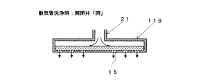
図12〜図14は、図9〜図11に示す散気管11Aを、大口径の散気孔19を設けない直管型の散気管11Bに置き換えた本発明の変形例を示す。
図12は、散気運転時の状態を示す説明図である。
図13は、散気管洗浄時に開閉弁31を開にした状態を示す説明図である。
図14は、散気管洗浄時に開閉弁31を閉にした状態を示す説明図である。
12 to 14 show a modification of the present invention in which the diffuser tube 11A shown in FIGS. 9 to 11 is replaced with a straight
FIG. 12 is an explanatory diagram showing a state during the aeration operation.
FIG. 13 is an explanatory view showing a state in which the on-off valve 31 is opened at the time of cleaning the air diffuser.
FIG. 14 is an explanatory view showing a state in which the on-off valve 31 is closed during the diffusing tube cleaning.
図12〜図14に示す例示においても、十分水深(水圧)があれば、短時間(0.5m進むのに0.2秒)で散気管11Bを被処理液で満たすことができる。そのため、短時間で開閉弁31を開け閉めすることで、散気管11B内に被処理液が流出入し、この脈動によって散気管11B内の空気噴出口(小口径の散気孔15)廻りの固形物を湿潤化及び剥離し、除去できる。
また、短時間での開閉弁31の操作のため、膜洗浄用空気の途切れが最小限に抑えられ、膜の閉塞に影響が無く、膜濾過運転を行いながら散気管11Bの洗浄が可能となる。
Also in the illustrations shown in FIGS. 12 to 14, if there is sufficient water depth (water pressure), the
Further, since the operation of the on-off valve 31 in a short time, the interruption of the membrane cleaning air is minimized, there is no influence on the blockage of the membrane, and the diffusing
散気管11Bの洗浄のため被処理液を散気管11B内に逆流させる方法において、空気噴出口(小口径の散気孔15)廻りを洗浄するために大気圧まで下げる必要はない。
図13に示すように、散気管11Bの上部まで空気を押し込むのに必要な圧力未満とすれば、散気管11Bからの空気噴き出しが無くなり、散気管11Bに被処理液が水圧により瞬時に逆流する。
また、開閉弁31を数回操作することで、空気噴出口(小口径の散気孔15)廻りで被処理液の出入りが起こり(脈動)、洗浄される。
In the method in which the liquid to be treated flows back into the
As shown in FIG. 13, if the pressure is less than that required to push air up to the upper part of the
Further, by operating the on-off valve 31 several times, the liquid to be treated enters and leaves (pulsates) around the air outlet (small-aperture diffuser hole 15) and is washed.
図15は、本発明の第二実施形態に係る散気装置10Aを示す。
本実施形態に係る散気装置10Aは、開閉弁31を開閉弁31と同等の応答性を有するバルブ(以下、応答性の早いバルブと称する)31aと開閉弁31の応答性より遅い応答性を有するバルブ(以下、応答性の遅いバルブと称する)31bとに置き換える構成とした点で、本発明の第一実施形態に係る散気装置10とは異なる。
なお、本実施形態に係る散気装置10Aのその他の構成は、本発明の第一実施形態に係る散気装置10と同じであるから同一符号を用いて示し、その他の構成の説明を省略し、応答性の早いバルブ31a及び応答性の遅いバルブ31bについて説明する。
FIG. 15 shows an air diffuser 10A according to the second embodiment of the present invention.
The
In addition, since the other structure of 10 A of air diffusion apparatuses which concern on this embodiment is the same as the
本実施形態に係る散気装置10Aでは、応答性の早いバルブ31aを分岐配管33に接続し、応答性の遅いバルブ31bを応答性の早いバルブ31aに対して直列に接続している。
本実施形態に係る散気装置10Aにおいて、応答性の早いバルブ31aには、応答性が瞬時〜1秒程度と開閉弁31と同等である電磁弁などを用いる。また、応答性の遅いバルブ31bには、応答性が1秒〜15秒程度と開閉弁31の応答性より遅い電動式ボール弁などを用いる。
In the air diffuser 10A according to the present embodiment, the valve 31a having quick response is connected to the branch pipe 33, and the valve 31b having slow response is connected in series to the valve 31a having fast response.
In the
次に、本実施形態に係る散気装置10Aの作用を説明する。
本実施形態に係る散気装置10Aの散気状態時には、応答性の早いバルブ31a及び応答性の遅いバルブ31bを閉とする。
そして、本実施形態に係る散気装置10Aを散気状態から大気圧下開放状態に切り替える前に、応答性の早いバルブ31aは閉を維持し、応答性の遅いバルブ31bを開とする。
Next, the operation of the air diffuser 10A according to the present embodiment will be described.
When the air diffuser 10A according to the present embodiment is in the diffused state, the valve 31a having a fast response and the valve 31b having a slow response are closed.
Then, before switching the diffuser 10A according to the present embodiment from the diffused state to the open state under atmospheric pressure, the valve 31a having a fast response is kept closed and the valve 31b having a slow response is opened.
次に、本実施形態に係る散気装置10Aの大気圧下開放状態時には、応答性の早いバルブ31a及び応答性の遅いバルブ31bを開とする。
次に、本実施形態に係る散気装置10Aの散気状態への復帰時には、応答性の早いバルブ31aは開を維持し、応答性の遅いバルブ31bを閉とする。
次に、本実施形態に係る散気装置10Aの散気状態への復帰時には、応答性の早いバルブ31a及び応答性の遅いバルブ31bを閉とする。
Next, when the diffuser 10A according to the present embodiment is opened under atmospheric pressure, the valve 31a having a fast response and the valve 31b having a slow response are opened.
Next, when the diffuser 10A according to the present embodiment returns to the diffused state, the valve 31a having a fast response is kept open and the valve 31b having a slow response is closed.
Next, when the diffuser 10A according to the present embodiment returns to the diffused state, the valve 31a having a fast response and the valve 31b having a slow response are closed.
このように、本実施形態では、応答性の異なるバルブ31a,31bを利用することで、瞬間的な大気圧下への開放(応答性の遅いバルブを開にした後、応答性の速いバルブを開)と緩やかな散気状態への復帰(応答性の遅いバルブを閉にした後、応答性の速いバルブを閉)を自動で行うことができる。
その他の効果は、本発明の第一実施形態に係る散気装置10と同じであるから省略する。
As described above, in this embodiment, by using the valves 31a and 31b having different responsiveness, an instantaneous release to the atmospheric pressure (after opening the slow responsive valve, the fast responsive valve is opened. (Open) and return to a mild diffused state (after closing the valve with slow response, close the valve with fast response) can be performed automatically.
Since other effects are the same as those of the
図16は、本発明の第三実施形態に係る散気装置10Bを示す。
本実施形態に係る散気装置10Bは、応答性の遅いバルブ31bを分岐配管33に接続し、応答性の早いバルブ31aを応答性の遅いバルブ31bに対して直列に接続する構成とした点で、本発明の第二実施形態に係る散気装置10Aとは異なる。
なお、本実施形態に係る散気装置10Bのその他の構成は、本発明の第二実施形態に係る散気装置10Aと同じであるから同一符号を用いて示し、その他の構成の説明を省略し、応答性の早いバルブ31a及び応答性の遅いバルブ31bについて説明する。
FIG. 16 shows an air diffuser 10B according to the third embodiment of the present invention.
In the air diffuser 10B according to the present embodiment, the valve 31b having a slow response is connected to the branch pipe 33, and the valve 31a having a fast response is connected in series to the valve 31b having a slow response. This is different from the diffuser 10A according to the second embodiment of the present invention.
In addition, since the other structure of the air diffusion apparatus 10B which concerns on this embodiment is the same as the air diffusion apparatus 10A which concerns on 2nd embodiment of this invention, it shows using the same code | symbol and abbreviate | omits description of another structure. The quick response valve 31a and the slow response valve 31b will be described.
次に、本実施形態に係る散気装置10Bの作用を説明する。
本実施形態に係る散気装置10Bの散気状態時には、応答性の早いバルブ31a及び応答性の遅いバルブ31bを閉とする。
そして、本実施形態に係る散気装置10Bを散気状態から大気圧下開放状態に切り替える前に、応答性の早いバルブ31aは閉を維持し、応答性の遅いバルブ31bを開とする。
Next, the operation of the air diffuser 10B according to this embodiment will be described.
When the air diffuser 10B according to the present embodiment is in an air diffused state, the valve 31a having a fast response and the valve 31b having a slow response are closed.
And before switching the diffuser 10B which concerns on this embodiment from a diffused state to an open state under atmospheric pressure, the valve 31a with quick responsiveness is maintained closed, and the valve 31b with slow responsiveness is opened.
次に、本実施形態に係る散気装置10Bの大気圧下開放状態時には、応答性の早いバルブ31a及び応答性の遅いバルブ31bを開とする。
次に、本実施形態に係る散気装置10Bの散気状態への復帰時には、応答性の早いバルブ31aは開を維持し、応答性の遅いバルブ31bを閉とする。
次に、本実施形態に係る散気装置10Bの散気状態への復帰時には、応答性の早いバルブ31a及び応答性の遅いバルブ31bを閉とする。
Next, when the air diffuser 10B according to the present embodiment is in an open state under atmospheric pressure, the valve 31a having a fast response and the valve 31b having a slow response are opened.
Next, when the diffuser 10B according to the present embodiment returns to the diffused state, the valve 31a having a fast response is kept open and the valve 31b having a slow response is closed.
Next, when the diffuser 10B according to the present embodiment returns to the diffused state, the valve 31a having a fast response and the valve 31b having a slow response are closed.
このように、本実施形態では、応答性の異なるバルブ31a,31bを利用することで、瞬間的な大気圧下への開放(応答性の遅いバルブを開にした後、応答性の速いバルブを開)と緩やかな散気状態への復帰(応答性の遅いバルブを閉にした後、応答性の速いバルブを閉)を自動で行うことができる。
その他の効果は、本発明の第一実施形態に係る散気装置10と同じであるから省略する。
As described above, in this embodiment, by using the valves 31a and 31b having different responsiveness, an instantaneous release to the atmospheric pressure (after opening the slow responsive valve, the fast responsive valve is opened. (Open) and return to a mild diffused state (after closing the valve with slow response, close the valve with fast response) can be performed automatically.
Since other effects are the same as those of the
図17は、本発明の第四実施形態に係る散気装置10Cを示す。
本実施形態に係る散気装置10Cは、応答性の早いバルブ31a及び応答性の遅いバルブ31bを分岐配管33aを介して分岐配管33に並列に接続する構成とした点で、本発明の第三実施形態に係る散気装置10Bとは異なる。
なお、本実施形態に係る散気装置10Cのその他の構成は、本発明の第三実施形態に係る散気装置10Bと同じであるから同一符号を用いて示し、その他の構成の説明を省略し、応答性の早いバルブ31a及び応答性の遅いバルブ31bについて説明する。
FIG. 17 shows an air diffuser 10C according to the fourth embodiment of the present invention.
The air diffuser 10C according to the present embodiment has a configuration in which a valve 31a having a fast response and a valve 31b having a slow response are connected in parallel to the branch pipe 33 via the branch pipe 33a. It is different from the air diffuser 10B according to the embodiment.
The other configuration of the air diffuser 10C according to the present embodiment is the same as that of the air diffuser 10B according to the third embodiment of the present invention, so that the same reference numerals are used and the description of the other components is omitted. The quick response valve 31a and the slow response valve 31b will be described.
次に、本実施形態に係る散気装置10Cの作用を説明する。
本実施形態に係る散気装置10Cの散気状態時には、応答性の早いバルブ31a及び応答性の遅いバルブ31bを閉とする。
Next, the operation of the air diffuser 10C according to the present embodiment will be described.
When the air diffuser 10C according to the present embodiment is in the diffused state, the valve 31a having a fast response and the valve 31b having a slow response are closed.
そして、本実施形態に係る散気装置10Cの大気圧下開放状態時には、応答性の早いバルブ31a及び応答性の遅いバルブ31bを同時に開とする。又は、応答性の遅いバルブ31bより応答性の早いバルブ31aを先行して開とする。なお、応答性の早いバルブ31a及び応答性の遅いバルブ31bを同時に開としても、時間差で応答性の早いバルブ31aが先に全開となり圧が抜ける。
次に、本実施形態に係る散気装置10Cの散気状態への復帰時には、応答性の早いバルブ31a及び応答性の遅いバルブ31bを同時に閉とする。又は、応答性の遅いバルブ31bより応答性の早いバルブ31aを先行して閉とする。
Then, when the diffuser 10C according to the present embodiment is in an open state under atmospheric pressure, the valve 31a having a fast response and the valve 31b having a slow response are simultaneously opened. Alternatively, the valve 31a having a faster response than the valve 31b having a slower response is opened in advance. Even if the valve 31a having a fast response and the valve 31b having a slow response are simultaneously opened, the valve 31a having a fast response is fully opened first and the pressure is released due to a time difference.
Next, when the diffuser 10C according to the present embodiment returns to the diffused state, the valve 31a having a fast response and the valve 31b having a slow response are simultaneously closed. Alternatively, the valve 31a having a faster response than the valve 31b having a slower response is closed in advance.
このように、本実施形態では、応答性の異なるバルブ31a,31bを利用することで、瞬間的な大気圧下への開放(応答性の遅いバルブを閉にした後、応答性の速いバルブを開)と緩やかな散気状態への復帰(応答性の遅いバルブを閉にした後、応答性の速いバルブを閉)を自動で行うことができる。
その他の効果は、本発明の第一実施形態に係る散気装置10と同じであるから省略する。
As described above, in this embodiment, by using the valves 31a and 31b having different responsiveness, an instantaneous release to the atmospheric pressure (after closing the slow responsive valve, the fast responsive valve (Open) and return to a mild diffused state (after closing the valve with slow response, close the valve with fast response) can be performed automatically.
Since other effects are the same as those of the
1 反応槽
3 膜ユニット
9 原水供給配管
10 散気装置
11 散気管
13 直管
15 小口径の散気孔
17 エルボ部
19 大口径の散気孔
21 空気供給配管
23 ブロア
25 逆止弁
27 空気フィルタ
29 風量計
31 開閉弁
31a 応答性の早いバルブ
31b 応答性の遅いバルブ
33 分岐配管
DESCRIPTION OF
Claims (10)
反応槽内に浸漬され、前記浸漬型膜分離装置の下方に略水平に設置され前記反応槽の底面側に複数の空気噴出口を設ける散気管と、
前記散気管に先端を接続され基端部を反応槽液位から外部空気中に延設される空気供給配管と、
前記空気供給配管の基端部に接続され、散気運転時及び散気管洗浄時に駆動されるブロワと、
前記空気供給配管の前記反応槽液位から外部空気中の途中に分岐配管を介して接続され、前記散気管の洗浄時に開放される開閉弁と
を備え、
前記開閉弁が、応答性の異なる二つのバルブで構成され、開動作と閉動作とで動作する順序を切り替えるよう構成されている
ことを特徴とする散気装置。 An air diffuser used in a submerged membrane separator,
A diffusing tube that is immersed in a reaction vessel, is installed substantially horizontally below the submerged membrane separator, and has a plurality of air outlets on the bottom side of the reaction vessel;
An air supply pipe having a distal end connected to the air diffuser and a base end extending from the reaction tank liquid level to the outside air; and
A blower connected to the base end portion of the air supply pipe and driven at the time of air diffusion operation and air pipe cleaning;
Which is connected from the reactor liquid level of the air supply pipe through a branch pipe in the middle in the external air, and an opening and closing valve which is opened during the cleaning of the diffuser tube,
The on-off valve is composed of two valves having different responsiveness, and is configured to switch the order of operation between the opening operation and the closing operation.
Air diffuser apparatus according to claim and this.
前記散気管は、前記反応槽の底面側に複数の空気噴出口を設けた直管と、前記直管の管端に接続され、前記反応槽の底面側に開口するエルボ部とで構成されている
ことを特徴とする散気装置。 The air diffuser according to claim 1.
The air diffuser is composed of a straight pipe provided with a plurality of air jets on the bottom surface side of the reaction tank, and an elbow portion connected to a pipe end of the straight pipe and opening on the bottom face side of the reaction tank. A diffuser characterized by that.
前記開閉弁の動作が、制御装置に備わるタイマーに設定された時間で開閉を繰り返すよう構成されている
ことを特徴とする散気装置。 In the aeration apparatus according to claim 1 or 2,
An air diffuser characterized in that the operation of the on-off valve is configured to repeat opening and closing for a time set in a timer provided in the control device.
前記空気供給配管は、前記ブロワの吐出部側から前記散気管に向けて順に逆止弁、空気フィルタ、風量計及び前記分岐配管を介して前記開閉弁を設けている
ことを特徴とする散気装置。 The air diffuser according to any one of claims 1 to 3 ,
The air supply pipe is provided with the on-off valve via a check valve, an air filter, an air flow meter, and the branch pipe in order from the discharge part side of the blower toward the diffuser pipe. apparatus.
前記ブロワを運転しながら前記開閉弁を0.2秒間から10秒間の何れかの時間開放する操作を繰り返す
ことを特徴とする散気装置の洗浄方法。 In the washing | cleaning method of the aeration apparatus as described in any one of Claims 1 thru | or 4 ,
An operation of opening the on-off valve for any time from 0.2 seconds to 10 seconds while operating the blower is repeated.
前記ブロワを運転しながら前記開閉弁を0.2秒間から10秒間の何れかの時間開放し、前記散気管内の圧力を減少させ、前記反応槽内の被処理液を前記エルボ部の開口及び前記複数の空気噴出口から逆流入させ、散気時に前記複数の空気噴出口を逆流し散気管内部に凝固した固形物を湿潤させ、且つ前記散気管内を前記ブロワ側へ固形物を引き剥がして移動させ、前記散気管に逆流入した前記被処理液を、前記空気供給配管の反応槽の被処理液位から所定距離まで逆流入させる工程と、
前記ブロワを運転しながら前記開閉弁を0.2秒間から10秒間の何れかの時間閉止し、前記複数の空気噴出口からの前記被処理液を排出させて洗浄する工程と
を繰り返すことを特徴とする散気装置の洗浄方法。 In the washing | cleaning method of the aeration apparatus of Claim 5 ,
While the blower is in operation, the on-off valve is opened for any time from 0.2 seconds to 10 seconds to reduce the pressure in the diffuser tube, and the liquid to be treated in the reaction tank is opened in the elbow section and The plurality of air jets are allowed to flow backward, the plurality of air jets flow backward during the aeration to wet the solid matter solidified inside the diffuser, and the solids are peeled off to the blower inside the diffuser. And moving the processed liquid that has flowed back into the air diffuser into a predetermined distance from the liquid level to be processed in the reaction tank of the air supply pipe; and
Repeating the steps of closing the on-off valve for any time from 0.2 seconds to 10 seconds while operating the blower, and discharging and cleaning the liquid to be treated from the plurality of air jets. A method for cleaning an air diffuser.
前記開閉弁の開閉操作時間は0.2秒〜10秒間、前記開閉弁の操作間隔は0.5秒〜15秒間、前記開閉弁の操作回数は3回〜15回とする
ことを特徴とする散気装置の洗浄方法。 In the washing | cleaning method of the aeration apparatus of Claim 5 or Claim 6 ,
The on-off valve opening / closing operation time is 0.2 to 10 seconds, the on-off valve operation interval is 0.5 to 15 seconds, and the on-off valve operation frequency is 3 to 15 times. How to clean the diffuser.
前記開閉弁の開閉操作時間は0.2秒〜3秒間、前記開閉弁の操作間隔は0.5秒〜10秒間、前記開閉弁の操作回数は3回〜10回とする
ことを特徴とする散気装置の洗浄方法。 In the washing | cleaning method of the aeration apparatus of Claim 5 or Claim 6 ,
The opening / closing operation time of the opening / closing valve is 0.2 second to 3 seconds, the operation interval of the opening / closing valve is 0.5 second to 10 seconds, and the number of operations of the opening / closing valve is 3 times to 10 times. How to clean the diffuser.
前記空気噴出口廻りの固形物を湿潤化及び剥離させる際の管内流速は2.4m/s以上である
ことを特徴とする散気装置の洗浄方法。 In the washing | cleaning method of the aeration apparatus as described in any one of Claim 5 thru | or 7 ,
A method for cleaning an air diffuser, wherein a flow rate in the pipe when the solid around the air outlet is wetted and peeled is 2.4 m / s or more.
前記被処理液を前記散気管を介して前記空気供給配管へ逆流入させる前記供給配管の反応槽の被処理液位からの距離Δh’を、2.4m以上反応槽液高以下とする
ことを特徴とする散気装置の洗浄方法。 In the washing | cleaning method of the aeration apparatus as described in any one of Claim 5 thru | or 9 ,
The distance Δh ′ from the level of the liquid to be treated of the reaction tank of the supply pipe through which the liquid to be treated flows back into the air supply pipe through the air diffuser is set to 2.4 m or more and the reaction tank liquid height or less. A method for cleaning an air diffuser.
Priority Applications (1)
| Application Number | Priority Date | Filing Date | Title |
|---|---|---|---|
| JP2014062076A JP6239418B2 (en) | 2014-03-25 | 2014-03-25 | Air diffuser and cleaning method |
Applications Claiming Priority (1)
| Application Number | Priority Date | Filing Date | Title |
|---|---|---|---|
| JP2014062076A JP6239418B2 (en) | 2014-03-25 | 2014-03-25 | Air diffuser and cleaning method |
Publications (2)
| Publication Number | Publication Date |
|---|---|
| JP2015182036A JP2015182036A (en) | 2015-10-22 |
| JP6239418B2 true JP6239418B2 (en) | 2017-11-29 |
Family
ID=54349227
Family Applications (1)
| Application Number | Title | Priority Date | Filing Date |
|---|---|---|---|
| JP2014062076A Active JP6239418B2 (en) | 2014-03-25 | 2014-03-25 | Air diffuser and cleaning method |
Country Status (1)
| Country | Link |
|---|---|
| JP (1) | JP6239418B2 (en) |
Families Citing this family (8)
| Publication number | Priority date | Publication date | Assignee | Title |
|---|---|---|---|---|
| FR3061663B1 (en) * | 2017-01-06 | 2019-05-17 | Suez Groupe | IMPROVED IMMERED MEMBRANE AERATION SYSTEM |
| JP2018167249A (en) * | 2017-03-30 | 2018-11-01 | メタウォーター株式会社 | Wastewater treatment system, air supply amount control equipment and air supply amount control method |
| JP7169777B2 (en) * | 2017-09-11 | 2022-11-11 | 東京エレクトロン株式会社 | SUBSTRATE LIQUID PROCESSING APPARATUS, SUBSTRATE LIQUID PROCESSING METHOD, AND STORAGE MEDIUM |
| US11594430B2 (en) | 2017-09-11 | 2023-02-28 | Tokyo Electron Limited | Substrate liquid processing apparatus, substrate liquid processing method and recording medium |
| JP6918667B2 (en) * | 2017-09-29 | 2021-08-11 | 三菱ケミカルアクア・ソリューションズ株式会社 | Cleaning method of air diffuser and air diffuser |
| JP7311242B2 (en) | 2017-11-30 | 2023-07-19 | 三菱ケミカル株式会社 | Air diffuser, air diffusion method, and water treatment device |
| KR20230070302A (en) | 2020-10-27 | 2023-05-22 | 신메이와 고교 가부시키가이샤 | State monitoring system, state monitoring device, state monitoring method, and recording medium |
| MX2021013125A (en) * | 2021-10-26 | 2023-04-27 | Xavier Valdes De La Garza | Maintenance and exchange system of air diffusers from the outside of the reactor, in aeration systems of aerobic bioreactors without interrupting the wastewater treatment process. |
Family Cites Families (5)
| Publication number | Priority date | Publication date | Assignee | Title |
|---|---|---|---|---|
| JPH0620520B2 (en) * | 1986-09-18 | 1994-03-23 | 三菱重工業株式会社 | Cleaning method of air diffuser nozzle |
| JP3859447B2 (en) * | 2000-12-22 | 2006-12-20 | 株式会社クボタ | Aeration method and apparatus |
| JP2002307091A (en) * | 2001-04-16 | 2002-10-22 | Kubota Corp | Cleaning method of diffuser |
| JP2005279495A (en) * | 2004-03-30 | 2005-10-13 | Toray Ind Inc | Immersed membrane separator, washing method for diffuser, and membrane separation method |
| JP5182413B2 (en) * | 2005-02-24 | 2013-04-17 | 東レ株式会社 | Immersion type membrane separator, method of cleaning a diffuser and membrane separation method |
-
2014
- 2014-03-25 JP JP2014062076A patent/JP6239418B2/en active Active
Also Published As
| Publication number | Publication date |
|---|---|
| JP2015182036A (en) | 2015-10-22 |
Similar Documents
| Publication | Publication Date | Title |
|---|---|---|
| JP6239418B2 (en) | Air diffuser and cleaning method | |
| JP5249237B2 (en) | Scum remover | |
| KR20120028348A (en) | Membrane cleaning with pulsed gas slugs and global aeration | |
| JP2010194524A (en) | Immersion type membrane separator, washing method of air diffuser, and membrane separation method | |
| JP2011092835A (en) | Method for operating aeration device | |
| JP2011218266A (en) | Microbubble sewage regenerating apparatus having scum mechanism | |
| JP6010319B2 (en) | Bath system | |
| JP5439344B2 (en) | Membrane separation biological treatment equipment | |
| CN103459332A (en) | Operating method for air diffusion apparatus | |
| JP5066819B2 (en) | Water quality measuring device | |
| JP2009161601A (en) | Organism desulfurization apparatus | |
| JP2006247498A (en) | Membrane washing method and apparatus | |
| JP2005279495A (en) | Immersed membrane separator, washing method for diffuser, and membrane separation method | |
| JP6411051B2 (en) | Immersion membrane separator and method for operating the same | |
| JP5381731B2 (en) | Bathtub cleaning device and hot water supply device with reheating function provided with the same | |
| JP4274903B2 (en) | Cleaning method for air diffuser | |
| JPH10286444A (en) | Immersion type membrane filter device | |
| JP2008237605A (en) | Bathtub washing apparatus | |
| JP2002166290A (en) | Diffuser and method for washing the same | |
| JP2011005445A (en) | Water treatment apparatus | |
| JP2009066511A (en) | Washing method of filtration apparatus | |
| JP5891197B2 (en) | Scum remover | |
| JP2014000572A (en) | Operation method of diffuser | |
| JPH11347377A (en) | Solid-liquid separation apparatus and washing method thereof | |
| JP2006035175A (en) | Bath water cleaner |
Legal Events
| Date | Code | Title | Description |
|---|---|---|---|
| A621 | Written request for application examination |
Free format text: JAPANESE INTERMEDIATE CODE: A621 Effective date: 20161101 |
|
| RD01 | Notification of change of attorney |
Free format text: JAPANESE INTERMEDIATE CODE: A7426 Effective date: 20170510 |
|
| RD03 | Notification of appointment of power of attorney |
Free format text: JAPANESE INTERMEDIATE CODE: A7423 Effective date: 20170510 |
|
| RD04 | Notification of resignation of power of attorney |
Free format text: JAPANESE INTERMEDIATE CODE: A7424 Effective date: 20170512 |
|
| A977 | Report on retrieval |
Free format text: JAPANESE INTERMEDIATE CODE: A971007 Effective date: 20170517 |
|
| A131 | Notification of reasons for refusal |
Free format text: JAPANESE INTERMEDIATE CODE: A131 Effective date: 20170606 |
|
| A521 | Request for written amendment filed |
Free format text: JAPANESE INTERMEDIATE CODE: A523 Effective date: 20170807 |
|
| TRDD | Decision of grant or rejection written | ||
| A01 | Written decision to grant a patent or to grant a registration (utility model) |
Free format text: JAPANESE INTERMEDIATE CODE: A01 Effective date: 20171031 |
|
| A61 | First payment of annual fees (during grant procedure) |
Free format text: JAPANESE INTERMEDIATE CODE: A61 Effective date: 20171101 |
|
| R150 | Certificate of patent or registration of utility model |
Ref document number: 6239418 Country of ref document: JP Free format text: JAPANESE INTERMEDIATE CODE: R150 |
|
| R250 | Receipt of annual fees |
Free format text: JAPANESE INTERMEDIATE CODE: R250 |