JP6234905B2 - Elevator car - Google Patents

Elevator car Download PDF

Info

Publication number
JP6234905B2
JP6234905B2 JP2014191397A JP2014191397A JP6234905B2 JP 6234905 B2 JP6234905 B2 JP 6234905B2 JP 2014191397 A JP2014191397 A JP 2014191397A JP 2014191397 A JP2014191397 A JP 2014191397A JP 6234905 B2 JP6234905 B2 JP 6234905B2
Authority
JP
Japan
Prior art keywords
floor
car
horizontal portion
design surface
skirting board
Prior art date
Legal status (The legal status is an assumption and is not a legal conclusion. Google has not performed a legal analysis and makes no representation as to the accuracy of the status listed.)
Active
Application number
JP2014191397A
Other languages
Japanese (ja)
Other versions
JP2016060613A5 (en
JP2016060613A (en
Inventor
島田 勝博
勝博 島田
真剣 山本
真剣 山本
Current Assignee (The listed assignees may be inaccurate. Google has not performed a legal analysis and makes no representation or warranty as to the accuracy of the list.)
Hitachi Ltd
Original Assignee
Hitachi Ltd
Priority date (The priority date is an assumption and is not a legal conclusion. Google has not performed a legal analysis and makes no representation as to the accuracy of the date listed.)
Filing date
Publication date
Application filed by Hitachi Ltd filed Critical Hitachi Ltd
Priority to JP2014191397A priority Critical patent/JP6234905B2/en
Priority to CN201510471374.6A priority patent/CN106185552B/en
Publication of JP2016060613A publication Critical patent/JP2016060613A/en
Publication of JP2016060613A5 publication Critical patent/JP2016060613A5/ja
Application granted granted Critical
Publication of JP6234905B2 publication Critical patent/JP6234905B2/en
Active legal-status Critical Current
Anticipated expiration legal-status Critical

Links

Images

Landscapes

  • Cage And Drive Apparatuses For Elevators (AREA)

Description

本発明は、かご室内に幅木が設けられたエレベータの乗りかごに関する。   The present invention relates to an elevator car provided with baseboards in a car room.

エレベータの乗りかご内には、側板とかご床を支持する床枠とのボルト締結部を覆う為に幅木が設置されている。この幅木の取り付け作業性を向上する技術が特許文献1に開示されている。特許文献1では、幅木は、塗装された鋼板、あるいは、印刷された鋼板を折り曲げることにより、乗りかごの内側に露出される意匠面となる側面と、床枠に固定するための上部折り曲げ部とが一体に形成されている。そして、上部折り曲げ部に、複数個の長穴を設けると共に、床枠の内側周面に複数個の保持手段、例えば板ばねを設置し、この板ばねを上部折り曲げ部に設けられた長穴に挿入することで、幅木を床枠に固定することが記載されている。   A baseboard is installed in the elevator car to cover the bolt fastening portion between the side plate and the floor frame that supports the car floor. Patent Document 1 discloses a technique for improving the skirting attachment workability. In patent document 1, a base board is a coated steel plate or the side surface used as the design surface exposed inside a passenger car by bend | folding the printed steel plate, and the upper bending part for fixing to a floor frame. And are integrally formed. A plurality of elongated holes are provided in the upper bent portion, and a plurality of holding means, for example, leaf springs, are installed on the inner peripheral surface of the floor frame, and the leaf springs are formed in the elongated holes provided in the upper bent portion. It is described that the baseboard is fixed to the floor frame by insertion.

特開2002−114469号公報JP 2002-114469 A

しかしながら、前述のような板ばねを幅木に設けられた長穴に挿入することで幅木を固定する構成では、軽量化や原価の低減のため、幅木となる鋼板の板厚寸法を薄くすることが難しいという課題があった。すなわち、鋼板の板厚寸法を薄くすると、幅木としての断面性能/剛性が落ちてしまい、幅木固定の為に必要とされる板ばねのばね圧に対応することができなくなる。   However, in the configuration in which the skirting board is fixed by inserting the leaf spring as described above into the long hole provided in the skirting board, the thickness of the steel plate used as the skirting board is reduced in order to reduce weight and cost. There was a problem that it was difficult to do. That is, when the plate thickness dimension of the steel plate is reduced, the cross-sectional performance / rigidity as a base plate is lowered, and it becomes impossible to cope with the spring pressure of the plate spring required for fixing the base plate.

また、断面性能/剛性を確保するために板厚寸法を所定値以上にすると、幅木は鋼板を折り曲げ成型するものであるため、比較的厚い板厚寸法でも折り曲げ成型が可能な鋼板を選択する必要がある。そのため、幅木の素材が限定されてしまうという問題があった。   In addition, if the plate thickness dimension is set to a predetermined value or more in order to ensure the cross-sectional performance / rigidity, the baseboard folds the steel plate, so a steel plate that can be bent even with a relatively thick plate thickness is selected. There is a need. For this reason, there is a problem that the material of the baseboard is limited.

そこで、本発明は、幅木の断面性能/剛性を確保しつつ、幅木となる鋼板の板厚寸法を薄くすることができるエレベータの乗りかごを提供することを目的とする。   Accordingly, an object of the present invention is to provide an elevator car that can reduce the plate thickness of a steel plate to be a baseboard while ensuring the cross-sectional performance / rigidity of the baseboard.

上記課題を解決するために、例えば特許請求の範囲に記載の構成を採用する。本願は、上記課題を解決する手段を複数含んでいるが、その一例を挙げるならば、かご室の床面となるかご床と、かご室を介してかご床と対向する位置に設けられた天井と、かご室の側面を囲むようにかご床の周囲に立設された複数の側板と、かご床及び側板を支持する床枠と、側板とかご床との間に設けられる幅木と、幅木をかご床側に付勢するばね部材とを有するエレベータの乗りかごにおいて、幅木は、かご室側に配置される意匠面を有する意匠面部と、意匠面部の上部側から水平方向に延設され、ばね部材が嵌合する複数の嵌合孔を有する上部水平部と、意匠面部の下部側から水平方向に延設され、かご床に接する下部水平部と、上部水平部及び下部水平部の間において上下方向に延在するように設けられる補強部とを備え、意匠面部、上部水平部、下部水平部及び補強部は一枚の鋼板を折り曲げることにより一体に形成されていることを特徴とする。   In order to solve the above problems, for example, the configuration described in the claims is adopted. The present application includes a plurality of means for solving the above-described problems. For example, a car floor that serves as a floor surface of a car room and a ceiling provided at a position facing the car floor through the car room. A plurality of side plates standing around the car floor so as to surround the side of the car room, a floor frame supporting the car floor and the side plates, a baseboard provided between the side plate and the car floor, and a width In an elevator car having a spring member that biases the wood toward the car floor, the baseboard extends in the horizontal direction from the design surface part having the design surface arranged on the car room side and the upper side of the design surface part An upper horizontal portion having a plurality of fitting holes into which the spring member is fitted, a lower horizontal portion extending in a horizontal direction from the lower side of the design surface portion, and in contact with the car floor, and an upper horizontal portion and a lower horizontal portion. And a reinforcing surface provided so as to extend in the vertical direction between, and the design surface , Upper horizontal portion, a lower horizontal portion and the reinforcing portion is characterized by being formed integrally by bending a single steel plate.

本発明によれば、エレベータの乗りかごにおいて、幅木の断面性能/剛性を確保しつつ、幅木となる鋼板の板厚寸法を低減することができる。   ADVANTAGE OF THE INVENTION According to this invention, the board thickness dimension of the steel plate used as a base board can be reduced, ensuring the cross-sectional performance / rigidity of a base board in the elevator car.

本発明の第1の実施形態に係るエレベータの乗りかごの内部の様子を示す概略構成図である。It is a schematic block diagram which shows the mode inside the elevator car which concerns on the 1st Embodiment of this invention. 本発明の第1の実施形態に係るエレベータの乗りかごの要部の断面構成図である。It is a section lineblock diagram of an important section of a elevator car concerning a 1st embodiment of the present invention. 本発明の第1の実施形態に係る幅木の概略斜視図である。It is a schematic perspective view of a skirting board concerning a 1st embodiment of the present invention. 床枠の側面と背面とに取り付けられる2本の幅木をかご室の内側から透過して見た構成図である。It is the block diagram which permeate | transmitted two baseboards attached to the side surface and back surface of a floor frame from the inner side of the cab. ばね部材が取り付けられる側から見た幅木の概略斜視図である。It is a schematic perspective view of the base board seen from the side to which a spring member is attached. ばね部材が取り付けられる側から見た幅木の概略構成図である。It is a schematic block diagram seen from the side where a spring member is attached. 本発明の第1の実施形態に係る幅木の展開図である。It is an expanded view of the baseboard which concerns on the 1st Embodiment of this invention. 本発明の第2の実施形態に係るエレベータの乗りかごにおける幅木の概略斜視図である。It is a schematic perspective view of the baseboard in the elevator car which concerns on the 2nd Embodiment of this invention.

以下、本発明の実施形態に係るエレベータの乗りかごの一例を、図面を参照しながら説明する。なお、本発明は以下の例に限定されるものではない。   Hereinafter, an example of an elevator car according to an embodiment of the present invention will be described with reference to the drawings. In addition, this invention is not limited to the following examples.

《第1の実施形態》
[エレベータの乗りかごの内部の構成]
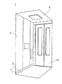
図1に、本発明の第1の実施形態に係るエレベータの乗りかごの内部の様子を示す概略構成を示し、図2に、要部の断面構成を示す。図1に示すように、本実施形態のエレベータの乗りかご1は、かご床2と、側板3と、扉部10と、天井4と、かご床2と側板3との間に設けられる幅木7とを備え、これらに囲まれる空間が乗客等を収容できるかご室となる。
<< First Embodiment >>
[Inside elevator car configuration]
FIG. 1 shows a schematic configuration showing an internal state of an elevator car according to the first embodiment of the present invention, and FIG. 2 shows a cross-sectional configuration of a main part. As shown in FIG. 1, an elevator car 1 according to this embodiment includes a car floor 2, a side plate 3, a door 10, a ceiling 4, and a skirting board provided between the car floor 2 and the side plate 3. 7 and a space surrounded by these is a cab that can accommodate passengers and the like.

かご床2は、図2に示すように、かご室側の面が水平な床面となる台状の部材で構成され、かご室側に面する側の床面には、タイルなどで構成された床板23が設けられている。本実施形態では、かご床は、床面が四角形状の板状のかご床本体21と、かご床本体21の径よりも小さい径を有する台状の部材で構成された土台部22とで構成され、土台部22上面にかご床本体21が設けられた構成とされている。天井4は、かご室を介してかご床2と対向する位置に設けられている。側板3は、かご室の側面を囲むようにかご床2の周囲に立設され、扉部10を除く位置に複数設けられる。詳述すると、側板3は、扉部10が設けられる前面に対向する背面と、対向して設けられる2つの側面に設けられる。扉部10は、かご室の前面に設けられ、開閉可能に設けられている。扉部10はかご室への出入り口となる。   As shown in FIG. 2, the car floor 2 is composed of a trapezoidal member whose surface on the cab side is a horizontal floor surface, and the floor surface facing the cab side is composed of tiles or the like. A floor plate 23 is provided. In the present embodiment, the car floor is configured by a plate-like car floor main body 21 having a quadrangular floor surface and a base portion 22 made of a trapezoidal member having a diameter smaller than the diameter of the car floor main body 21. The car floor main body 21 is provided on the upper surface of the base portion 22. The ceiling 4 is provided at a position facing the car floor 2 through the car room. The side plates 3 are erected around the car floor 2 so as to surround the side surface of the car room, and a plurality of side plates 3 are provided at positions excluding the door portion 10. More specifically, the side plate 3 is provided on the back surface facing the front surface on which the door portion 10 is provided and on two side surfaces provided facing each other. The door part 10 is provided in the front surface of the cab, and is provided so that opening and closing is possible. The door part 10 becomes an entrance to the cab.

[要部の構成]
次に、エレベータの乗りかご1の要部について説明する。図2に示すように、エレベータの乗りかご1は、かご床2及び側板3を支持する床枠5と、かご床2と側板3との間に設けられる幅木7と、幅木7を固定するためのばね部材8とを備える。
[Configuration of main parts]
Next, the main part of the elevator car 1 will be described. As shown in FIG. 2, the elevator car 1 has a floor frame 5 that supports the car floor 2 and the side plate 3, a baseboard 7 provided between the car floor 2 and the side plate 3, and a baseboard 7 fixed thereto. And a spring member 8.

[床枠]
まず、床枠5について説明する。床枠5は、かご床2を支持する側に水平面を備える底部51と、底部51の側面から底部51の水平面に対して側板3が配置される方向に延在する側壁部52と、側壁部52の底部51側とは反対側の端部においてかご室側に延在する水平面を備える上端部55とを備える。側壁部52は、かご床2のかご床本体21と土台部22との間の段差部の形状に沿うように設けられた段差部52aを有している。本実施形態では、かご床2の土台部22の底面が床枠5の底部51に当接し、かご床2のかご床本体21の底面が床枠5の段差部52aの水平面に当接することで、かご床2が床枠5に支持される。すなわち、本実施形態では、かご床2にかかる荷重は、床枠5の底部51及び段差部52aによって受けられる。
[Floor frame]
First, the floor frame 5 will be described. The floor frame 5 includes a bottom portion 51 having a horizontal surface on the side supporting the car floor 2, a side wall portion 52 extending from a side surface of the bottom portion 51 in a direction in which the side plate 3 is disposed with respect to a horizontal surface of the bottom portion 51, and a side wall portion. 52 is provided with an upper end 55 having a horizontal surface extending toward the cab side at the end opposite to the bottom 51 side. The side wall portion 52 has a step portion 52 a provided along the shape of the step portion between the car floor main body 21 and the base portion 22 of the car floor 2. In the present embodiment, the bottom surface of the base portion 22 of the car floor 2 is in contact with the bottom portion 51 of the floor frame 5, and the bottom surface of the car floor body 21 of the car floor 2 is in contact with the horizontal surface of the stepped portion 52 a of the floor frame 5. The car floor 2 is supported by the floor frame 5. That is, in this embodiment, the load applied to the car floor 2 is received by the bottom 51 and the step 52a of the floor frame 5.

また、床枠5の上端部55のかご室側に向かう方向の幅の長さは、側板3の厚みとほぼ同じに形成されており、上端部55の所望の位置には、側板3を床枠5の上端部55に固定するためのボルト締結孔53が設けられている。本実施形態では、側板3と床枠5の上端部55とが、ボルト締結孔53においてボルト6とナット(図示を省略する)で締め付けられることによって固定される。これにより、側板3が床枠5の上端部55に支持される。   Further, the length of the width of the upper end portion 55 of the floor frame 5 in the direction toward the cab is substantially the same as the thickness of the side plate 3, and the side plate 3 is placed on the floor at a desired position of the upper end portion 55. A bolt fastening hole 53 for fixing to the upper end portion 55 of the frame 5 is provided. In the present embodiment, the side plate 3 and the upper end portion 55 of the floor frame 5 are fixed by being tightened with bolts 6 and nuts (not shown) in the bolt fastening holes 53. As a result, the side plate 3 is supported by the upper end portion 55 of the floor frame 5.

さらに、床枠5の側壁部52には、段差部52aと上端部55との間の領域の所望の位置に、ばね部材8を固定するためのボルト締結孔54が設けられている。ボルト締結孔54では、側壁部52のかご室側にばね部材8がボルト9(本発明の固定部)とナット(図示を省略する)によって固定される。   Further, the side wall 52 of the floor frame 5 is provided with a bolt fastening hole 54 for fixing the spring member 8 at a desired position in a region between the stepped portion 52 a and the upper end 55. In the bolt fastening hole 54, the spring member 8 is fixed to the cab side of the side wall portion 52 by a bolt 9 (fixing portion of the present invention) and a nut (not shown).

[幅木]
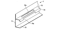
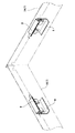
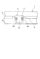
次に、幅木7について説明する。本実施形態では、幅木7の構造が特徴を有する。図3は、幅木7の概略斜視図である。また、図4は、かご室の側面と背面とに取り付けられる2本の幅木7(7A,7B)をかご室の内側から透過して見た構成図であり、図5は、ばね部材8が取り付けられる側から見た幅木7の概略斜視図である。また、図6は、ばね部材8が取り付けられる側から見た幅木7の概略構成図である。以下の説明において、背面の幅木7と側面の幅木7とを区別する場合には、それぞれ「背面幅木7A」、「側面幅木7B」と記載し、区別しない場合には「幅木7」と記載する。
[Baseboard]
Next, the skirting board 7 will be described. In this embodiment, the structure of the baseboard 7 has a feature. FIG. 3 is a schematic perspective view of the skirting board 7. FIG. 4 is a structural view of the two baseboards 7 (7A, 7B) attached to the side surface and the back surface of the cab, as seen from the inside of the cab, and FIG. It is a schematic perspective view of the skirting board 7 seen from the side to which is attached. FIG. 6 is a schematic configuration diagram of the skirting board 7 viewed from the side on which the spring member 8 is attached. In the following description, when distinguishing the back skirting board 7 and the side skirting board 7 from each other, they are described as “back skirting board 7A” and “side skirting board 7B”, respectively. 7 ”.

幅木7は、かご室側において、床枠5の上端部55と側板3とのボルト締結孔53を被覆するために床枠5と側板3との間に設けられる。本実施形態では、幅木7は、扉部10が設けられる位置を除くかご床2の3つの辺にそれぞれ一つずつ設けられており、それぞれの幅木7は、側板3が設けられるかご床2の一辺に対応する長さに形成されている。図2及び図3に示すように、幅木7は、意匠面部71と、下部水平部73と、上部水平部72と、補強部74とを備え、これらは一枚の鋼板を折り曲げることによって一体に形成されている。   The skirting board 7 is provided between the floor frame 5 and the side plate 3 in order to cover the bolt fastening holes 53 between the upper end portion 55 of the floor frame 5 and the side plate 3 on the cab side. In the present embodiment, one baseboard 7 is provided on each of the three sides of the car floor 2 except for the position where the door portion 10 is provided, and each baseboard 7 is provided on the car floor on which the side plate 3 is provided. 2 to a length corresponding to one side. As shown in FIGS. 2 and 3, the skirting board 7 includes a design surface portion 71, a lower horizontal portion 73, an upper horizontal portion 72, and a reinforcing portion 74, which are integrated by bending a single steel plate. Is formed.

意匠面部71は、かご室側に露出される意匠面71aを有している。意匠面71aは、図2に示すように側板3のかご室側の面とほぼ平行な面である。かご床2の床面に直交する方向における意匠面部71の長さ、すなわち意匠面部71の短手方向の長さは、床面に配置された床板23と側板3との間の長さとほぼ等しく構成される。また、図4に示すように、背面幅木7Aにおいては、意匠面部71の短手方向に直交する長手方向の長さは対応する床面の辺と同じ長さに構成され、側面幅木7Bにおいては、意匠面部71の長手方向の長さは対応する床面の辺よりも若干長く構成されている。   The design surface part 71 has a design surface 71a exposed to the cab side. As shown in FIG. 2, the design surface 71 a is a surface substantially parallel to the surface of the side plate 3 on the cab side. The length of the design surface portion 71 in the direction orthogonal to the floor surface of the car floor 2, that is, the length in the short direction of the design surface portion 71 is substantially equal to the length between the floor plate 23 and the side plate 3 arranged on the floor surface. Composed. Further, as shown in FIG. 4, in the back base 7A, the length in the longitudinal direction orthogonal to the short direction of the design surface portion 71 is configured to be the same as the side of the corresponding floor surface, and the side base 7B The length of the design surface portion 71 in the longitudinal direction is slightly longer than the corresponding side of the floor surface.

下部水平部73は、意匠面部71の下部側(かご床2側)の端部からかご室とは反対側に延在して設けられている。意匠面71aに直交する方向における下部水平部73の長さは、幅木7を床枠5に取り付けたときに下部水平部73の端部が床枠5の側壁部52に当接する長さに構成されている。   The lower horizontal portion 73 is provided so as to extend from an end portion on the lower side (the car floor 2 side) of the design surface portion 71 to the side opposite to the cab. The length of the lower horizontal portion 73 in the direction orthogonal to the design surface 71 a is such that the end of the lower horizontal portion 73 contacts the side wall portion 52 of the floor frame 5 when the baseboard 7 is attached to the floor frame 5. It is configured.

上部水平部72は、下部水平部73よりも上部側(側板3側)であって、後述するばね部材8のばね部81が配置される位置に設けられ、意匠面部71から床枠5の側壁部52側に延在する水平面を有するように構成されている。また、上部水平部72の側壁部52に固定されるばね部81に対向する位置には、後述するばね部材8のばね部81が嵌合する嵌合孔72aが設けられている。したがって、上部水平部72における意匠面71aに直交する方向の長さは、ばね部材8のばね部81が嵌合する嵌合孔72aを形成できる程度の幅に構成されている。   The upper horizontal portion 72 is provided on the upper side (side plate 3 side) of the lower horizontal portion 73 and is provided at a position where a spring portion 81 of the spring member 8 to be described later is disposed, and from the design surface portion 71 to the side wall of the floor frame 5. It is comprised so that it may have the horizontal surface extended to the part 52 side. A fitting hole 72 a into which a spring portion 81 of the spring member 8 described later is fitted is provided at a position facing the spring portion 81 fixed to the side wall portion 52 of the upper horizontal portion 72. Therefore, the length of the upper horizontal portion 72 in the direction orthogonal to the design surface 71a is configured to have such a width that the fitting hole 72a into which the spring portion 81 of the spring member 8 is fitted can be formed.

補強部74は、上部水平部72の側壁部52側の端部から鉛直下方向に延在して設けられ、意匠面71aと平行な平面を有するように構成されている。補強部74は幅木7の断面性能/剛性を向上させるために設けられる部位である。また、補強部74の、側壁部52に設けられるボルト締結孔54に対向する位置には切り欠き部74aが設けられている。切り欠き部74aは、ボルト締結孔54に取り付けられるボルト9が補強部74に当たるのを回避する為に設けられている。   The reinforcing portion 74 is provided to extend vertically downward from the end portion of the upper horizontal portion 72 on the side wall portion 52 side, and is configured to have a plane parallel to the design surface 71a. The reinforcing portion 74 is a portion provided to improve the cross-sectional performance / rigidity of the skirting board 7. Further, a cutout portion 74 a is provided at a position of the reinforcing portion 74 facing the bolt fastening hole 54 provided in the side wall portion 52. The notch 74 a is provided to avoid the bolt 9 attached to the bolt fastening hole 54 from hitting the reinforcing portion 74.

また、本実施形態では、下部水平部73、上部水平部72及び補強部74の長手方向の両端部は、図5に示すように、意匠面部71側から側壁部52側に向かうに連れて長手方向の長さが短くなるようなテーパ状に形成されている。本実施形態では、例えば下部水平部73は、所定の角度βで長手方向の長さが意匠面部71の長手方向の長さより短くなるように構成され、上部水平部72及び補強部74は、所定の角度αで長手方向の長さが意匠面部71の長さより短くなるように構成されている。   Moreover, in this embodiment, the both ends of the longitudinal direction of the lower horizontal part 73, the upper horizontal part 72, and the reinforcement part 74 are long as it goes to the side wall part 52 side from the design surface part 71 side, as shown in FIG. It is formed in a taper shape that shortens the length in the direction. In the present embodiment, for example, the lower horizontal portion 73 is configured so that the length in the longitudinal direction is shorter than the length in the longitudinal direction of the design surface portion 71 at a predetermined angle β, and the upper horizontal portion 72 and the reinforcement portion 74 are The length in the longitudinal direction at the angle α is shorter than the length of the design surface portion 71.

本実施形態では、下部水平部73、上部水平部72及び補強部74の長手方向の両端部をテーパ状に形成し、意匠面部71の長手方向の長さよりも短くすることによって、隣接する他の部材との緩衝を避けることができるので幅木7の取り付け時における取り扱いが容易になる。また、図4及び図5に示すように幅木7の角部が鈍角になるため、幅木7の取り扱い時の安全性を向上させることができる。   In the present embodiment, both ends in the longitudinal direction of the lower horizontal portion 73, the upper horizontal portion 72, and the reinforcing portion 74 are formed in a taper shape, and shorter than the length in the longitudinal direction of the design surface portion 71. Since buffering with a member can be avoided, the handling at the time of attachment of the base board 7 becomes easy. Moreover, since the corner | angular part of the baseboard 7 becomes an obtuse angle as shown in FIG.4 and FIG.5, the safety | security at the time of handling of the baseboard 7 can be improved.

図7は、本実施形態の幅木7の展開図である。本実施形態では、幅木7は、図6に示すような厚さ0.7mmの鋼板を折り曲げることによって形成されている。また、本実施形態における幅木7は、図6に示すように、長手方向の両端部において、下部水平部73、上部水平部72及び補強部74となる部分を面取りし、図6に示す形状の板状部材を折り曲げ加工することによって下部水平部73、上部水平部72及び補強部74の長手方向の両端部をテーパ状にすることができる。幅木7を構成する鋼板の材料としては、例えば、ステンレス鋼板を用いることができる。また、幅木7としては、塗装や印刷が施された各種鋼板を用いることができる。   FIG. 7 is a development view of the skirting board 7 of the present embodiment. In this embodiment, the skirting board 7 is formed by bending a 0.7 mm thick steel plate as shown in FIG. Further, as shown in FIG. 6, the skirting board 7 in the present embodiment has a shape shown in FIG. 6 by chamfering portions that become the lower horizontal portion 73, the upper horizontal portion 72, and the reinforcing portion 74 at both ends in the longitudinal direction. By bending the plate-like member, both ends in the longitudinal direction of the lower horizontal portion 73, the upper horizontal portion 72, and the reinforcing portion 74 can be tapered. As a material of the steel plate constituting the skirting board 7, for example, a stainless steel plate can be used. Moreover, as the skirting board 7, the various steel plates by which painting and printing were performed can be used.

[ばね部材]
次に、ばね部材8について説明する。ばね部材8は、平面が矩形状の板状部材で構成された取り付け部82と、取り付け部82の一端から延在して設けられたばね部81とを備えたいわゆる板ばねであり、取り付け部82及びばね部81は、一枚の板状部材を折り曲げることによって一体に形成されている。取り付け部82には、ばね部81が設けられる方向と直交する方向に並列した2つの長穴82aが形成されている。長穴82aは、ばね部81が設けられる方向に長い角丸長方形状(小判型)に形成されている。また、取り付け部82のばね部81とは反対側の端部は、ばね部81とほぼ並行となるように折り曲げられている。
[Spring member]
Next, the spring member 8 will be described. The spring member 8 is a so-called leaf spring that includes a mounting portion 82 that is formed of a plate-like member having a rectangular plane, and a spring portion 81 that extends from one end of the mounting portion 82. The spring portion 81 is integrally formed by bending a single plate-like member. The attachment portion 82 is formed with two elongated holes 82a arranged in parallel in a direction orthogonal to the direction in which the spring portion 81 is provided. The long hole 82a is formed in a rounded rectangular shape (oval shape) that is long in the direction in which the spring portion 81 is provided. Further, the end portion of the attachment portion 82 opposite to the spring portion 81 is bent so as to be substantially parallel to the spring portion 81.

ばね部81は、取り付け部82の平面に直交する方向に延在して設けられており、その断面形状は、取り付け部82側に窪み部が形成されるような断面凹形状に形成されている。断面凹形状に形成されたばね部81は、前述した幅木7の上部水平部72に設けられた嵌合孔72aに嵌合可能な大きさに形成されている。また、取り付け部82の平面に直交する方向におけるばね部81の幅は、側壁部52と幅木7の意匠面部71との間の隙間に収まる幅に構成されている。   The spring portion 81 is provided so as to extend in a direction orthogonal to the plane of the attachment portion 82, and the cross-sectional shape thereof is formed in a concave cross-section such that a depression is formed on the attachment portion 82 side. . The spring portion 81 having a concave cross section is formed in a size that can be fitted into the fitting hole 72a provided in the upper horizontal portion 72 of the base board 7 described above. Further, the width of the spring portion 81 in the direction orthogonal to the plane of the mounting portion 82 is configured to fit within the gap between the side wall portion 52 and the design surface portion 71 of the base board 7.

本実施形態では、取り付け部82を側壁部52のかご室側に当接させ、取り付け部82の長穴82aと側壁部52に設けられたボルト締結孔54とを位置あわせし、その後、ボルト9とナット(図示を省略する)で両者を固定する。このとき、ばね部材8のばね部81が幅木7の上部水平部72に設けられた嵌合孔72aに嵌合すると共に、ばね部81が上部水平部72を鉛直下方向に付勢することができる高さとなるように、ばね部材8の高さを調整する。本実施形態では、取り付け部82のボルト9が挿入される穴を長穴82aとすることにより、かご床2の床面に配置される床板23の厚さに応じて、ばね部材8の取り付け位置を調整することができる。   In the present embodiment, the attachment portion 82 is brought into contact with the cab side of the side wall portion 52, the elongated hole 82a of the attachment portion 82 and the bolt fastening hole 54 provided in the side wall portion 52 are aligned, and then the bolt 9 And fix them with nuts (not shown). At this time, the spring portion 81 of the spring member 8 is fitted into the fitting hole 72a provided in the upper horizontal portion 72 of the skirting board 7, and the spring portion 81 urges the upper horizontal portion 72 vertically downward. The height of the spring member 8 is adjusted so that the height can be achieved. In this embodiment, the attachment position of the spring member 8 is set according to the thickness of the floor plate 23 arranged on the floor surface of the car floor 2 by making the hole into which the bolt 9 of the attachment portion 82 is inserted into the long hole 82a. Can be adjusted.

〈幅木の取り付け方法〉
次に、本実施形態における幅木7の取り付け方法について説明する。まず、床枠5の側壁部52の所望の位置にばね部材8をボルト9とナット(図示を省略する)を用いて固定する。この場合、前述したように、床板23の厚みに応じてばね部材8が丁度いい高さとなるようにばね部材8を取り付ける。この高さは、ばね部材8のばね部81が幅木7の上部水平部72の嵌合孔72aに嵌合可能であると共に、ばね部81が上部水平部72を鉛直下方向に付勢可能な高さであり、ばね部81の最も低い位置が上部水平部72の高さよりも低くなる位置である。
<Attaching the skirting board>
Next, the attachment method of the baseboard 7 in this embodiment is demonstrated. First, the spring member 8 is fixed to a desired position of the side wall 52 of the floor frame 5 by using bolts 9 and nuts (not shown). In this case, as described above, the spring member 8 is attached so that the spring member 8 has the right height according to the thickness of the floor plate 23. This height is such that the spring portion 81 of the spring member 8 can be fitted into the fitting hole 72a of the upper horizontal portion 72 of the skirting board 7, and the spring portion 81 can urge the upper horizontal portion 72 vertically downward. The lowest position of the spring part 81 is a position where it is lower than the height of the upper horizontal part 72.

その後、幅木7の上部水平部72に設けられた嵌合孔72aにばね部材8のばね部81を嵌合させながら幅木7を床枠5に嵌め込む。これにより、ばね部材8のばね部81によって幅木7の上部水平部72は鉛直下方向に付勢されることに伴って下部水平部73がかご床2の床面側に押し付けられ、幅木7が床枠5に固定される。本実施形態では、幅木7が取り付けられる床枠5の3つの辺のうち、まず、扉部10を挟んで対向する2つの辺、すなわちかご室の両側面に側面幅木7Bを嵌め込み、次に、扉部10に対向する辺、すなわちかご室の背面側に背面幅木7Aを嵌め込む。なお、扉部10側にも幅木7を嵌め込む必要がある場合には、側面幅木7Bを嵌め込んだ後に、前面幅木を嵌め込む。   Thereafter, the skirting board 7 is fitted into the floor frame 5 while the spring part 81 of the spring member 8 is fitted into the fitting hole 72 a provided in the upper horizontal part 72 of the skirting board 7. As a result, the lower horizontal portion 73 is pressed against the floor surface side of the car floor 2 as the upper horizontal portion 72 of the skirting board 7 is biased vertically downward by the spring portion 81 of the spring member 8, and 7 is fixed to the floor frame 5. In the present embodiment, among the three sides of the floor frame 5 to which the skirting board 7 is attached, first, the side skirting boards 7B are fitted into two sides facing each other with the door portion 10 interposed therebetween, that is, both sides of the cab. The back skirting board 7A is fitted into the side facing the door portion 10, that is, the back side of the cab. In addition, when it is necessary to fit the baseboard 7 also to the door part 10, the front baseboard is inserted after the side baseboard 7B is inserted.

このとき、側面幅木7Bの長手方向の長さは床枠5の辺(かご室の辺)よりも少し長く形成されており、背面幅木7Aの長手方向の長さは床枠5の辺(かご室の辺)と同じに形成されている。したがって、図4に示すように、側面幅木7Bの意匠面部71に背面幅木7Aの両端部が当接する形で背面幅木7Aが床枠(図2参照)に嵌め込まれる。このため、側面幅木7Bと背面幅木7Aとの間の隙間調整が容易になる。以上の作業により、幅木7の取り付けが完了する。そして、幅木7が取り付けられることにより、図2に示すように、床枠5と側板3とを固定するボルト9が被覆され、側板3と床板23との間の隙間がかご室側から見えなくなるように隠される。   At this time, the length in the longitudinal direction of the side baseboard 7B is formed slightly longer than the side of the floor frame 5 (side of the cab), and the length in the longitudinal direction of the back baseboard 7A is the side of the floor frame 5. It is formed the same as (the side of the cab). Therefore, as shown in FIG. 4, the back base 7A is fitted into the floor frame (see FIG. 2) in such a manner that both ends of the back base 7A come into contact with the design surface 71 of the side base 7B. For this reason, the clearance adjustment between the side baseboard 7B and the back baseboard 7A becomes easy. With the above operation, the installation of the baseboard 7 is completed. Then, as shown in FIG. 2, the base plate 7 is attached to cover the bolts 9 that fix the floor frame 5 and the side plate 3, and the gap between the side plate 3 and the floor plate 23 can be seen from the cab side. Hidden to disappear.

本実施形態では、幅木7において補強部74が設けられることにより、幅木7の断面性能/剛性を向上させることができる。したがって、補強部74を設けることにより、幅木7を形成するための鋼板の厚みを従来のものよりも薄くした場合にも、幅木7に必要な所望の断面性能/剛性を確保することができるため、幅木7の軽量化及び原価低減を図ることができる。   In the present embodiment, the cross section performance / rigidity of the skirting board 7 can be improved by providing the reinforcing portion 74 in the skirting board 7. Therefore, by providing the reinforcing portion 74, the desired cross-sectional performance / rigidity required for the skirting board 7 can be ensured even when the thickness of the steel plate for forming the skirting board 7 is made thinner than the conventional one. Therefore, the weight of the skirting board 7 can be reduced and the cost can be reduced.

従来の幅木7では、所望の断面剛性を得るために1.2mm以上の厚みの鋼板を用いる必要があった。一方で、幅木7は一枚の板状部材を折り曲げることによって所定の形状に加工されるが、厚みが1.2mm以上のステンレス鋼板を用いた場合、曲げ成型が困難となり、一枚の板状部材を折り曲げて形成する幅木は実用化することができなかった。すなわち、幅木7において、補強部74が設けられていない場合には、厚みが1.2mmよりも小さい鋼板を用いた場合には、ばね部材8に耐え得る剛性が得られず、厚みを1.2mm以上にした場合には曲げ成型ができないという問題があった。   In the conventional skirting board 7, in order to obtain desired cross-sectional rigidity, it was necessary to use a steel plate having a thickness of 1.2 mm or more. On the other hand, the skirting board 7 is processed into a predetermined shape by bending a single plate-like member. However, when a stainless steel plate having a thickness of 1.2 mm or more is used, it becomes difficult to bend and form a single plate. A skirting board formed by bending a shaped member could not be put into practical use. That is, in the skirting board 7, when the reinforcing portion 74 is not provided, when a steel plate having a thickness smaller than 1.2 mm is used, the rigidity that can withstand the spring member 8 cannot be obtained, and the thickness is 1 When the thickness is 2 mm or more, there is a problem that bending molding cannot be performed.

これに対し、本実施形態では、補強部74を設けることにより、曲げ成型が可能な厚み0.7mmのステンレス鋼板を用いた場合にも必要な断面性能/剛性を確保することができることが検証により判明している。このように、本実施形態では、鋼板の板厚寸法を低減できることから、折り曲げ成型が容易となり、幅木7として使用可能な素材の選択肢を広げることができる。   On the other hand, in the present embodiment, it is verified by providing the reinforcing portion 74 that the necessary cross-sectional performance / rigidity can be ensured even when a 0.7 mm thick stainless steel plate that can be bent is used. It turns out. Thus, in this embodiment, since the plate | board thickness dimension of a steel plate can be reduced, bending molding becomes easy and the choice of the raw material which can be used as the baseboard 7 can be expanded.

本実施形態では、補強部74は、上部水平部72の端部から鉛直下方向に延びるように形成されているが、下部水平部73の床枠5側の端部から鉛直上方向に延びるように形成してもよい。すなわち、補強部74はその延在方向が、上部水平部72と下部水平部73との間の上下方向であればよい。ところで、幅木7の断面性能/剛性を向上させる方法として、下部水平部73や上部水平部72の短手方向の長さを長くする方法も考えられる。しかしながら、下部水平部73や上部水平部72の短手方向の長さを長くするよりも、上部水平部72及び下部水平部73間において上下方向に延在する補強部74を設ける方が、下部水平部73や上部水平部72の短手方向の長さを長くするよりも、意匠面部71を曲がりにくくすることができる。したがって、補強部74は、上部水平部72又は下部水平部73の端部から上下方向に延びるように形成することが好ましい。   In the present embodiment, the reinforcing portion 74 is formed to extend vertically downward from the end of the upper horizontal portion 72, but extends vertically upward from the end of the lower horizontal portion 73 on the floor frame 5 side. You may form in. That is, the extending direction of the reinforcing portion 74 may be the vertical direction between the upper horizontal portion 72 and the lower horizontal portion 73. By the way, as a method of improving the cross-sectional performance / rigidity of the skirting board 7, a method of increasing the length of the lower horizontal portion 73 and the upper horizontal portion 72 in the short direction is also conceivable. However, rather than increasing the length of the lower horizontal portion 73 and the upper horizontal portion 72 in the short side direction, it is preferable to provide the reinforcing portion 74 extending vertically between the upper horizontal portion 72 and the lower horizontal portion 73. The design surface portion 71 can be made harder to bend than the length in the short direction of the horizontal portion 73 and the upper horizontal portion 72 is increased. Therefore, the reinforcing portion 74 is preferably formed so as to extend in the vertical direction from the end of the upper horizontal portion 72 or the lower horizontal portion 73.

また、本実施形態のように、補強部74を上部水平部72の端部から鉛直下方向に延びるように設けることにより、ばね部材8に対する幅木7の強度も高めることができる。すなわち、幅木7を固定する際、ばね部材8によって上部水平部72が鉛直方向に付勢されることで幅木7が固定されるが、上部水平部72側に補強部74を設けることで、ばね部材8からの押圧力に対する上部水平部72の強度を高めることができる。なお、本実施形態では、補強部74はその平面が意匠面71aと平行であり、鉛直方向に延びるように形成されているが、必ずしも鉛直方向である必要はない。例えば、補強部74は、上部水平部72と下部水平部73との間で上下方向に延在していればよく、意匠面71aに対して斜め方向に延在していてもよい。   Further, by providing the reinforcing portion 74 so as to extend vertically downward from the end portion of the upper horizontal portion 72 as in the present embodiment, the strength of the baseboard 7 with respect to the spring member 8 can be increased. That is, when the baseboard 7 is fixed, the baseboard 7 is fixed by urging the upper horizontal portion 72 in the vertical direction by the spring member 8, but by providing the reinforcing portion 74 on the upper horizontal portion 72 side. The strength of the upper horizontal portion 72 against the pressing force from the spring member 8 can be increased. In the present embodiment, the reinforcing portion 74 is formed so that its plane is parallel to the design surface 71a and extends in the vertical direction, but it is not necessarily in the vertical direction. For example, the reinforcement part 74 should just extend in the up-down direction between the upper horizontal part 72 and the lower horizontal part 73, and may be extended in the diagonal direction with respect to the design surface 71a.

また、本実施形態では、補強部74に切り欠き部74aが設けられる。これにより、幅木7を取り付ける際に、ばね部材8を固定するためのボルト9に補強部74が当たるのを回避することができる。本実施形態では、切り欠き部74aは一方が開口した矩形状に形成されているが、穴状に形成してもよく、ボルト9が補強部74に当たるのを回避できる形状であればいかなる形状であってもよい。   In the present embodiment, the reinforcing portion 74 is provided with a notch 74a. Thereby, when attaching the base board 7, it can avoid that the reinforcement part 74 hits the volt | bolt 9 for fixing the spring member 8. FIG. In the present embodiment, the cutout portion 74a is formed in a rectangular shape with one opening, but may be formed in a hole shape, and may have any shape as long as the bolt 9 can be prevented from hitting the reinforcing portion 74. There may be.

《第2の実施形態》
次に、本発明の第2の実施形態に係るエレベータの乗りかごについて説明する。本実施形態のエレベータの乗りかごは、幅木の構成(特に、側面幅木の構成)が第1の実施形態と異なる。図8は、本実施形態の幅木70の概略構成図である。本実施形態のエレベータの乗りかごの全体の構成については第1の実施形態と同様であるから説明を省略し、また、図8において、図5に対応する部分には同一符号を付し重複説明を省略する。
<< Second Embodiment >>
Next, an elevator car according to the second embodiment of the present invention will be described. The elevator car according to the present embodiment is different from the first embodiment in the configuration of baseboards (particularly, the configuration of side baseboards). FIG. 8 is a schematic configuration diagram of the skirting board 70 of the present embodiment. Since the overall configuration of the elevator car of this embodiment is the same as that of the first embodiment, the description thereof will be omitted. In FIG. 8, portions corresponding to those in FIG. Is omitted.

ところで、図4に示すような側面幅木7Bは、対向する2つの側面に設けられるが、側面幅木7Bのうち一方の幅木7を左側幅木、他方の幅木7を右側幅木としたとき、通常は左側幅木と右側幅木の長手方向の長さは同じである。したがって、左側幅木と右側幅木として同じものを用いることができれば、コストの低減や作業効率の向上に繋がる。しかしながら、幅木7を固定するためのばね部材8の床枠5への固定位置は、幅木7の長手方向の中心部に設けられるとは限らない。例えば、左側幅木及び右側幅木を固定するばね部材8が、それぞれ、幅木7の長手方向の中心部よりも扉部10側手前に対向するように配置された場合(すなわち、左右勝手違いでばね部材8が配置された場合)、左側幅木と右側幅木とでは、嵌合孔72a及び切り欠き部74aの位置を異なる位置に配置する必要がある。したがって、左側幅木と右側幅木とを共通の部材とすることができない。   By the way, side skirting boards 7B as shown in FIG. 4 are provided on two opposing side faces. Among the side skirting boards 7B, one skirting board 7 is a left skirting board, and the other skirting board 7 is a right skirting board. When this is done, the lengths in the longitudinal direction of the left skirting board and the right skirting board are usually the same. Therefore, if the same skirting board can be used as the left skirting board and the right skirting board, costs can be reduced and work efficiency can be improved. However, the fixing position of the spring member 8 for fixing the skirting board 7 to the floor frame 5 is not necessarily provided at the center of the skirting board 7 in the longitudinal direction. For example, when the spring member 8 that fixes the left baseboard and the right baseboard is disposed so as to face the front side of the door 10 with respect to the longitudinal center of the baseboard 7 (that is, the right and left sides are different) In the case where the spring member 8 is disposed), it is necessary to dispose the fitting hole 72a and the cutout portion 74a at different positions in the left skirting board and the right skirting board. Therefore, the left skirting board and the right skirting board cannot be a common member.

そこで、本実施形態では、図8に示すように、1つの幅木70に、左側幅木として用いる場合に使用可能な嵌合孔76及び切り欠き部78と、右側幅木として用いる場合に使用可能な嵌合孔77及び切り欠き部79の両方を予め形成する。そうすると、図8に示すように、幅木70を、例えば右側幅木として用いる場合には、左側幅木用の嵌合孔77及び切り欠き部79は使用されない。逆に、幅木70を、左側幅木として用いる場合には、右側幅木用の嵌合孔76及び切り欠き部78は使用されない。   Therefore, in the present embodiment, as shown in FIG. 8, a single baseboard 70 is used when used as a right baseboard, and a fitting hole 76 and a notch 78 that can be used when the baseboard 70 is used as a left baseboard. Both possible fitting holes 77 and notches 79 are pre-formed. Then, as shown in FIG. 8, when the skirting board 70 is used as, for example, the right skirting board, the fitting hole 77 and the notch 79 for the left skirting board are not used. On the other hand, when the skirting board 70 is used as the left skirting board, the fitting hole 76 and the notch 78 for the right skirting board are not used.

本実施形態では、側面に使用される幅木70において、左右勝手違いに取り付けられたばね部材8に対応可能な嵌合孔76,77及び切り欠き部78,79を設けることにより、左側幅木と右側幅木とで共通の部材を用いることができる。これにより、コストの低減や作業効率の向上を図ることができる。   In the present embodiment, in the baseboard 70 used on the side surface, by providing the fitting holes 76 and 77 and the cutout portions 78 and 79 that can correspond to the spring members 8 that are attached to the left and right sides, A common member can be used for the right skirting board. Thereby, reduction of cost and improvement of work efficiency can be aimed at.

以上、本発明について、実施形態に基づいて説明したが、本発明は上述の実施形態に記載した構成に限定されるものではなく、その趣旨を逸脱しない範囲において適宜その構成を変更することができるものである。例えば、上述した実施形態例は、本発明を分かりやすく説明するために詳細に説明したものであり、必ずしも説明した全ての構成を備えるものに限定されるものではない。また、ある実施形態の構成の一部を他の実施形態の構成に置き換えることが可能であり、また、ある実施形態の構成について他の実施形態の構成を加えることも可能である。また、各実施形態の構成の一部について、他の構成の追加・削除・置換をすることが可能である。   As described above, the present invention has been described based on the embodiment. However, the present invention is not limited to the configuration described in the above-described embodiment, and the configuration can be appropriately changed without departing from the gist thereof. Is. For example, the above-described exemplary embodiments have been described in detail for easy understanding of the present invention, and are not necessarily limited to those having all the configurations described. Further, a part of the configuration of an embodiment can be replaced with the configuration of another embodiment, and the configuration of another embodiment can be added to the configuration of an embodiment. In addition, it is possible to add, delete, and replace other configurations for a part of the configuration of each embodiment.

1…乗りかご、2…かご床、3…側板、4…天井、5…床枠、6…ボルト、7,70…幅木、7A…背面幅木、7B…側面幅木、8…ばね部材、9…ボルト、10…扉部、21…床本体、22…土台部、23…床板、51…底部、52…側壁部、53…ボルト締結孔、54…ボルト締結孔、55…上端部、71…意匠面部、71a…意匠面、72…上部水平部、72a,76,77…嵌合孔、73…下部水平部、74…補強部、74a,78,79…切り欠き部、81…ばね部、82…取り付け部、82a…長穴   DESCRIPTION OF SYMBOLS 1 ... Riding car, 2 ... Car floor, 3 ... Side board, 4 ... Ceiling, 5 ... Floor frame, 6 ... Bolt, 7,70 ... Skirting board, 7A ... Back skirting board, 7B ... Side skirting board, 8 ... Spring member , 9 ... bolt, 10 ... door part, 21 ... floor main body, 22 ... base part, 23 ... floor plate, 51 ... bottom part, 52 ... side wall part, 53 ... bolt fastening hole, 54 ... bolt fastening hole, 55 ... upper end part, 71 ... Design surface portion, 71a ... Design surface, 72 ... Upper horizontal portion, 72a, 76, 77 ... Fitting hole, 73 ... Lower horizontal portion, 74 ... Reinforcement portion, 74a, 78, 79 ... Notch portion, 81 ... Spring Part, 82 ... attachment part, 82a ... long hole

Claims (4)

かご室の床面となるかご床と、
かご室を介して前記かご床と対向する位置に設けられた天井と、
かご室の側面を囲むように前記かご床の周囲に立設された複数の側板と、
前記かご床及び前記側板を支持する床枠と、
前記側板と前記かご床との間に設けられる幅木と、
前記幅木を前記かご床側に付勢するばね部材とを有するエレベータの乗りかごにおいて、
前記幅木は、かご室側に配置される意匠面を有する意匠面部と、前記意匠面部の上部側から水平方向に延設され、前記ばね部材が嵌合する複数の嵌合孔を有する上部水平部と、前記意匠面部の下部側から水平方向に延設され、前記かご床に接する下部水平部と、前記上部水平部及び前記下部水平部の間において上下方向に延在するように設けられる補強部とを備え、前記意匠面部、前記上部水平部、前記下部水平部及び前記補強部は一枚の鋼板を折り曲げることにより一体に形成されている
ことを特徴とするエレベータの乗りかご。
A car floor to be the floor of the car room;
A ceiling provided at a position facing the car floor via a car room;
A plurality of side plates erected around the car floor so as to surround a side surface of the car room;
A floor frame that supports the car floor and the side plates;
A skirting board provided between the side plate and the car floor;
In an elevator car having a spring member that biases the skirting board toward the car floor,
The base board has a design surface portion having a design surface disposed on the cab side, and an upper horizontal portion extending in a horizontal direction from the upper side of the design surface portion and having a plurality of fitting holes into which the spring member is fitted. And a reinforcement that is provided so as to extend in the vertical direction between the lower horizontal portion that extends in the horizontal direction from the lower portion side of the design surface portion and contacts the car floor, and between the upper horizontal portion and the lower horizontal portion. And the design surface portion, the upper horizontal portion, the lower horizontal portion, and the reinforcing portion are integrally formed by bending a single steel plate.
前記補強部は、前記上部水平部の前記意匠面部側とは反対側の端部から前記下部水平部側に向かって延設されている
請求項1に記載のエレベータの乗りかご。
The elevator car according to claim 1, wherein the reinforcing portion extends from an end portion of the upper horizontal portion opposite to the design surface portion side toward the lower horizontal portion side.
前記ばね部材は固定部によって前記床枠に固定されており、
前記補強部の前記固定部に対向する部分には前記固定部と前記補強部との接触を回避するための切り欠き部が設けられている
請求項1又は2に記載のエレベータの乗りかご。
The spring member is fixed to the floor frame by a fixing portion,
The elevator car according to claim 1, wherein a portion of the reinforcing portion that faces the fixed portion is provided with a notch for avoiding contact between the fixed portion and the reinforcing portion.
前記下部水平部、上部水平部及び補強部の長手方向の両端部は、意匠面部側から離れる方向に向かうに連れて長手方向の長さが短くなるようなテーパ状に形成されている
請求項1〜3のいずれか一項に記載のエレベータの乗りかご。
The longitudinal ends of the lower horizontal portion, the upper horizontal portion, and the reinforcing portion are formed in a taper shape such that the length in the longitudinal direction becomes shorter toward the direction away from the design surface side. The elevator car as described in any one of -3.
JP2014191397A 2014-09-19 2014-09-19 Elevator car Active JP6234905B2 (en)

Priority Applications (2)

Application Number Priority Date Filing Date Title
JP2014191397A JP6234905B2 (en) 2014-09-19 2014-09-19 Elevator car
CN201510471374.6A CN106185552B (en) 2014-09-19 2015-08-04 The car of elevator

Applications Claiming Priority (1)

Application Number Priority Date Filing Date Title
JP2014191397A JP6234905B2 (en) 2014-09-19 2014-09-19 Elevator car

Publications (3)

Publication Number Publication Date
JP2016060613A JP2016060613A (en) 2016-04-25
JP2016060613A5 JP2016060613A5 (en) 2016-12-28
JP6234905B2 true JP6234905B2 (en) 2017-11-22

Family

ID=55795674

Family Applications (1)

Application Number Title Priority Date Filing Date
JP2014191397A Active JP6234905B2 (en) 2014-09-19 2014-09-19 Elevator car

Country Status (2)

Country Link
JP (1) JP6234905B2 (en)
CN (1) CN106185552B (en)

Families Citing this family (2)

* Cited by examiner, † Cited by third party
Publication number Priority date Publication date Assignee Title
KR101810812B1 (en) * 2017-01-20 2018-01-25 윤일식 Device for Coupling Wall-decoration Boards of an Elevator
CN107043063B (en) * 2017-05-15 2023-02-07 通祐电梯有限公司 Quick-mounting skirting board for elevator car

Family Cites Families (12)

* Cited by examiner, † Cited by third party
Publication number Priority date Publication date Assignee Title
JPS5935494Y2 (en) * 1979-05-22 1984-10-01 三菱電機株式会社 elevator car room
JP3539745B2 (en) * 1993-06-14 2004-07-07 株式会社日立ビルシステム Elevator car side plate
JP3382044B2 (en) * 1995-01-12 2003-03-04 株式会社東芝 Elevator cab
JPH1036043A (en) * 1996-07-19 1998-02-10 Hitachi Building Syst Co Ltd Car of elevator
JPH11322233A (en) * 1998-05-15 1999-11-24 Hitachi Building Systems Co Ltd Side plate of elevator car
JP2002114469A (en) * 2000-10-05 2002-04-16 Hitachi Ltd Car baseboard structure of elevator
JP2006137513A (en) * 2004-11-11 2006-06-01 Hitachi Ltd Elevator car and elevator device
JP2008024384A (en) * 2006-07-18 2008-02-07 Mitsubishi Electric Corp Elevator cage
JP5130800B2 (en) * 2007-06-27 2013-01-30 三菱電機株式会社 Elevator car room
CN201169477Y (en) * 2007-11-14 2008-12-24 上海德圣米高电梯有限公司 Embarkation elevator car suitable for outdoor operating
JP5344426B2 (en) * 2009-01-14 2013-11-20 東芝エレベータ株式会社 Elevator car
CN201825621U (en) * 2010-06-29 2011-05-11 江南嘉捷电梯股份有限公司 Connecting structure for upper car wall plate and end part rib of elevator car

Also Published As

Publication number Publication date
CN106185552A (en) 2016-12-07
JP2016060613A (en) 2016-04-25
CN106185552B (en) 2018-08-17

Similar Documents

Publication Publication Date Title
JP6138258B2 (en) Elevator guide rail fixing device
KR100827716B1 (en) Bracket for window and door frames
KR101173795B1 (en) Assemblable Truss Structure
JP6234905B2 (en) Elevator car
US10519006B2 (en) Elevator guide rail bracket and method for securing a guide rail
JP2008149888A (en) Support structure for power plant
JP5599415B2 (en) Elevator car frame
JP5330134B2 (en) Suspended ceiling structure and construction method
US9446794B2 (en) Fender panel support structure for vehicle
JP4902597B2 (en) Elevator car structure
JP2009107403A (en) Floor member structure of cargo bed of truck
JP7121806B2 (en) Elevator equipment assembly method
JP6633747B2 (en) Elevator cab wall
JP6340222B2 (en) Mounting bracket for diagonal reinforcement members
JP5405931B2 (en) Ceiling edge with shape retaining member, ceiling edge unit and ceiling surface structure
JP5864192B2 (en) Three-way elevator
JP2011143808A (en) Railroad vehicle body structure
JP4967262B2 (en) Seismic isolation elevator plate
JP6242176B2 (en) Elevator car floor and manufacturing method thereof
JP6672571B2 (en) Suspension bracket reinforcement structure
KR200461677Y1 (en) Dust and noise reduction panel for construction work
JP2013166616A (en) Elevator
JP2013006699A (en) Support structure of elevator rail
JP7288179B2 (en) Joint structure
JP2008196125A (en) Mounting structure of wall panel

Legal Events

Date Code Title Description
A521 Written amendment

Free format text: JAPANESE INTERMEDIATE CODE: A523

Effective date: 20161111

A621 Written request for application examination

Free format text: JAPANESE INTERMEDIATE CODE: A621

Effective date: 20161111

A977 Report on retrieval

Free format text: JAPANESE INTERMEDIATE CODE: A971007

Effective date: 20170928

TRDD Decision of grant or rejection written
A01 Written decision to grant a patent or to grant a registration (utility model)

Free format text: JAPANESE INTERMEDIATE CODE: A01

Effective date: 20171017

A61 First payment of annual fees (during grant procedure)

Free format text: JAPANESE INTERMEDIATE CODE: A61

Effective date: 20171025

R150 Certificate of patent or registration of utility model

Ref document number: 6234905

Country of ref document: JP

Free format text: JAPANESE INTERMEDIATE CODE: R150