JP6222965B2 - Recording apparatus and recording apparatus control method - Google Patents
Recording apparatus and recording apparatus control method Download PDFInfo
- Publication number
- JP6222965B2 JP6222965B2 JP2013080840A JP2013080840A JP6222965B2 JP 6222965 B2 JP6222965 B2 JP 6222965B2 JP 2013080840 A JP2013080840 A JP 2013080840A JP 2013080840 A JP2013080840 A JP 2013080840A JP 6222965 B2 JP6222965 B2 JP 6222965B2
- Authority
- JP
- Japan
- Prior art keywords
- ink
- carriage
- ink tank
- recording apparatus
- suction
- Prior art date
- Legal status (The legal status is an assumption and is not a legal conclusion. Google has not performed a legal analysis and makes no representation as to the accuracy of the status listed.)
- Active
Links
Images


Classifications
-
- B—PERFORMING OPERATIONS; TRANSPORTING
- B41—PRINTING; LINING MACHINES; TYPEWRITERS; STAMPS
- B41J—TYPEWRITERS; SELECTIVE PRINTING MECHANISMS, i.e. MECHANISMS PRINTING OTHERWISE THAN FROM A FORME; CORRECTION OF TYPOGRAPHICAL ERRORS
- B41J2/00—Typewriters or selective printing mechanisms characterised by the printing or marking process for which they are designed
- B41J2/005—Typewriters or selective printing mechanisms characterised by the printing or marking process for which they are designed characterised by bringing liquid or particles selectively into contact with a printing material
- B41J2/01—Ink jet
- B41J2/135—Nozzles
- B41J2/165—Preventing or detecting of nozzle clogging, e.g. cleaning, capping or moistening for nozzles
- B41J2/16517—Cleaning of print head nozzles
- B41J2/1652—Cleaning of print head nozzles by driving a fluid through the nozzles to the outside thereof, e.g. by applying pressure to the inside or vacuum at the outside of the print head
- B41J2/16532—Cleaning of print head nozzles by driving a fluid through the nozzles to the outside thereof, e.g. by applying pressure to the inside or vacuum at the outside of the print head by applying vacuum only
-
- B—PERFORMING OPERATIONS; TRANSPORTING
- B41—PRINTING; LINING MACHINES; TYPEWRITERS; STAMPS
- B41J—TYPEWRITERS; SELECTIVE PRINTING MECHANISMS, i.e. MECHANISMS PRINTING OTHERWISE THAN FROM A FORME; CORRECTION OF TYPOGRAPHICAL ERRORS
- B41J2/00—Typewriters or selective printing mechanisms characterised by the printing or marking process for which they are designed
- B41J2/005—Typewriters or selective printing mechanisms characterised by the printing or marking process for which they are designed characterised by bringing liquid or particles selectively into contact with a printing material
- B41J2/01—Ink jet
- B41J2/135—Nozzles
- B41J2/165—Preventing or detecting of nozzle clogging, e.g. cleaning, capping or moistening for nozzles
- B41J2/16517—Cleaning of print head nozzles
- B41J2/1652—Cleaning of print head nozzles by driving a fluid through the nozzles to the outside thereof, e.g. by applying pressure to the inside or vacuum at the outside of the print head
- B41J2/16523—Waste ink collection from caps or spittoons, e.g. by suction
-
- B—PERFORMING OPERATIONS; TRANSPORTING
- B41—PRINTING; LINING MACHINES; TYPEWRITERS; STAMPS
- B41J—TYPEWRITERS; SELECTIVE PRINTING MECHANISMS, i.e. MECHANISMS PRINTING OTHERWISE THAN FROM A FORME; CORRECTION OF TYPOGRAPHICAL ERRORS
- B41J2/00—Typewriters or selective printing mechanisms characterised by the printing or marking process for which they are designed
- B41J2/005—Typewriters or selective printing mechanisms characterised by the printing or marking process for which they are designed characterised by bringing liquid or particles selectively into contact with a printing material
- B41J2/01—Ink jet
- B41J2/135—Nozzles
- B41J2/165—Preventing or detecting of nozzle clogging, e.g. cleaning, capping or moistening for nozzles
- B41J2/16517—Cleaning of print head nozzles
- B41J2002/16573—Cleaning process logic, e.g. for determining type or order of cleaning processes
Description
本発明は記録装置及び記録装置の制御方法に関し、特に、例えば、インクジェット記録ヘッドを搭載した記録装置及びその装置で用いるインクジェット記録ヘッドの制御方法に関する。 The present invention relates to a recording apparatus and a control method of the recording apparatus, and more particularly, to a recording apparatus equipped with an inkjet recording head and an inkjet recording head control method used in the apparatus.
プリンタ、複写機、ファクシミリ等において画像や文字等の記録手段として用いられる記録装置のうちインクジェット記録装置(以下、記録装置)は、インクジェット記録ヘッド(以下、記録ヘッド)から記録媒体にインクを吐出して記録を行うものである。
その記録装置は、記録媒体の搬送方向と交差する方向に記録ヘッドを走査しながら記録を行うシリアル型の記録装置と、記録媒体の全幅に相当する記録長をもつフルライン記録ヘッドを定位置に保持して記録を行うライン型の記録装置とに大別できる。
Among recording apparatuses used as recording means for images, characters, etc. in printers, copiers, facsimiles, etc., inkjet recording apparatuses (hereinafter referred to as recording apparatuses) eject ink from an inkjet recording head (hereinafter referred to as recording head) onto a recording medium. Recording.
The recording apparatus includes a serial type recording apparatus that performs recording while scanning the recording head in a direction intersecting the conveyance direction of the recording medium, and a full-line recording head having a recording length corresponding to the entire width of the recording medium at a fixed position. It can be roughly classified into a line type recording apparatus that holds and records.
上記シリアル型の記録装置は通常、記録媒体を所定の位置にセットした後、記録媒体上を所定の方向に移動する記録ヘッドを搭載したキャリッジの往復移動と所定量の紙搬送とを繰り返すことにより記録媒体の全面にわたって画像を記録する。 The serial type recording apparatus normally sets a recording medium at a predetermined position, and then repeats a reciprocating movement of a carriage equipped with a recording head that moves in a predetermined direction on the recording medium and a predetermined amount of paper conveyance. An image is recorded over the entire surface of the recording medium.
また、カラー記録に対応し、インク色別に記録ヘッドを複数個備えた構成の記録装置も多く普及している。また、近年の高精細な写真画質の記録を実現する為に、記録ヘッドから吐出される液滴のサイズも小さくなっている。このような小サイズの液滴を吐出するために記録ヘッドのノズル径も小型化しており、10〜50μm程度の径のノズルを有する記録ヘッドが一般的なものとなっている。 In addition, a recording apparatus having a configuration that includes a plurality of recording heads corresponding to ink colors corresponding to color recording has been widely used. In order to realize high-definition photographic image recording in recent years, the size of droplets ejected from a recording head has also been reduced. In order to discharge such small droplets, the nozzle diameter of the recording head is also reduced, and a recording head having a nozzle having a diameter of about 10 to 50 μm is common.
このような記録装置には、インクタンクと記録ヘッドを分離・交換可能な構成を採用しているタイプのものがある。このようなタイプの記録装置の場合、インクタンクの交換時にインクタンクと記録ヘッドとの間のインク流路が一時的に露出するため、そのインク流路にゴミなどの異物が混入する場合がある。異物がインク流路内に進入し、ノズルに到達した場合、ゴミの大きさによってはノズルで目詰まりが生じ、インク吐出不良の原因となってしまう場合がある。 There is a type of such a recording apparatus that employs a configuration in which the ink tank and the recording head can be separated and replaced. In the case of such a type of recording apparatus, the ink flow path between the ink tank and the print head is temporarily exposed when the ink tank is replaced, so that foreign matter such as dust may be mixed in the ink flow path. . When foreign matter enters the ink flow path and reaches the nozzle, the nozzle may be clogged depending on the size of dust, which may cause ink ejection failure.
そのため、例えば、特許文献1に開示されているように、従来からもインクが供給される部分に異物の進入を阻止するフィルタを設ける構成がされている。 Therefore, for example, as disclosed in Japanese Patent Application Laid-Open No. H10-228707, a configuration is conventionally provided in which a filter that prevents foreign matter from entering the portion to which ink is supplied.
しかしながら上記従来例では、インクタンクが記録ヘッドから分離されると、インクを含んだフィルタが大気に晒されてしまう。その状態で長期間放置されると、揮発成分の蒸発によってインクの粘度が増し、フィルタが目詰まりする場合があった。フィルタに目詰まりが生じると、記録ヘッドへのインク供給がスムーズに行われず、これがインク吐出不良の原因となる場合がある。 However, in the above conventional example, when the ink tank is separated from the recording head, the filter containing ink is exposed to the atmosphere. If left in that state for a long time, the viscosity of the ink increases due to evaporation of volatile components, and the filter may become clogged. When the filter is clogged, the ink is not smoothly supplied to the recording head, which may cause ink ejection failure.
本発明は上記従来例に鑑みてなされたもので、インクタンク交換により記録ヘッドのインク受容口が長時間空気に晒された場合でもインク吐出不良を防止し良好な記録を維持することできる記録装置及びその装置で用いる制御方法を提供すること目的としている。 The present invention has been made in view of the above conventional example, and a recording apparatus capable of preventing ink discharge failure and maintaining good recording even when the ink receiving port of the recording head is exposed to air for a long time by replacing the ink tank. And a control method used in the apparatus.
上記目的を達成するために本発明の記録装置は次のような構成からなる。 In order to achieve the above object, the recording apparatus of the present invention has the following configuration.
即ち、インクを吐出する複数のノズル列が設けられた記録ヘッドを搭載するキャリッジと、前記記録ヘッドへ供給されるインクを収容し、前記キャリッジに装着可能なインクタンクと、前記キャリッジに配され前記インクタンクが装着されたときに当該インクタンクと当接するフィルタ部材と、前記キャリッジに対する前記インクタンクの装着の有無を検知する検知手段と、前記複数のノズル列からインクを吸引する吸引手段と、を備える記録装置であって、開閉可能な、前記記録装置のカバーと、前記カバーの開閉状態を検知するカバー検知手段と、前記検知手段により前記インクタンクが前記キャリッジに装着されていないことが検知された場合は、前記記録装置のメモリに格納されたインクの吸引を指示するフラグをONにし、前記インクタンクが前記キャリッジに装着されていることが検知された場合は、前記フラグをOFFにする制御手段と、をさらに備え、前記制御手段は、前記カバー検知手段により前記カバーの閉状態が検知されたタイミングで前記検知手段に前記インクタンクの装着の有無を検知させて、前記記録装置がソフトパワーOFFの操作が行われたタイミングにおいて、前記フラグがONの場合は前記吸引手段による吸引動作を行わせ、該タイミングにおいて前記フラグがOFFの場合は前記吸引手段による吸引動作を行わせないことを特徴とする。 That is, a carriage for mounting a recording head in which a plurality of Roh nozzle row is provided for discharging ink, containing an ink to be supplied to the recording head, and an ink tank can be attached to the carriage, is arranged on the carriage a filter member in contact with the ink tank when said ink tank is mounted, a detecting means for detecting the presence or absence of the mounting of the ink tank to the previous SL carriage, suction means for sucking the ink from the previous SL plurality of nozzle rows A cover of the recording apparatus that can be opened and closed, a cover detection unit that detects an open / closed state of the cover, and the ink tank is not attached to the carriage by the detection unit. If is sensed, and a flag to indicate the suction of ink stored in the memory of the recording device to oN, the Lee If the ink tank that is mounted on the carriage is detected, further comprising a control means for the flag to OFF, the control means, the closed state of the cover is detected by the cover detection means At the timing, the detection means detects whether or not the ink tank is attached, and when the recording apparatus is operated to turn off the soft power, if the flag is ON, the suction means performs the suction operation. When the flag is OFF at this timing, the suction operation by the suction means is not performed .
また本発明を別の側面から見れば、インクを吐出する複数のノズル列が設けられた記録ヘッドを搭載するキャリッジと、前記記録ヘッドへ供給されるインクを収容し前記キャリッジに装着可能なインクタンクと、前記キャリッジに配され前記インクタンクが装着されたときに当該インクタンクと当接するフィルタ部材と、前記キャリッジに対する前記インクタンクの装着の有無を検知する検知手段と、前記複数のノズル列からインクを吸引する吸引手段と、が設けられている記録装置の制御方法であって、開閉可能な、前記記録装置のカバーの開閉状態を検知する第1の工程と、前記第1の工程において前記カバーの閉状態が検知されたタイミングで前記インクタンクが前記キャリッジに装着されていないことが検知された場合は、前記記録装置のメモリに格納されたインクの吸引を指示するフラグをONにし、該タイミングで前記インクタンクが前記キャリッジに装着されていることが検知された場合は、前記フラグをOFFにする第2の工程と、前記記録装置がソフトパワーOFFの操作が行われたタイミングにおいて、前記フラグがONの場合は前記吸引手段による吸引動作を行わせ、該タイミングにおいて前記フラグがOFFの場合は前記吸引手段による吸引動作を行わせない第3の工程と、を有することを特徴とする記録装置の制御方法を備える。 According to another aspect of the present invention, a carriage on which a recording head provided with a plurality of nozzle rows for ejecting ink is mounted, and an ink tank that accommodates ink supplied to the recording head and can be mounted on the carriage. If a filter member in contact with the ink tank when said ink tank is arranged on the carriage is mounted, a detecting means for detecting the presence or absence of the mounting of the ink tank with respect to the carriage, the ink from the plurality of nozzle rows A first step of detecting an open / closed state of the cover of the recording apparatus that can be opened and closed, and the cover in the first step. If the ink tank at the timing when the closed state is detected in that is not mounted on the carriage is detected, the recording A flag to indicate the suction of ink stored in the memory of the location and to ON, if it is detected that the ink tank at the time is attached to the carriage, second step of the flag to OFF If the flag is ON at the timing when the soft power OFF operation is performed on the recording apparatus, the suction operation is performed by the suction means. If the flag is OFF at the timing, the suction is performed by the suction means. a control method for a recording apparatus characterized by comprising a third step of not performing the operation, the.
従って本発明によれば、インクタンク交換によりフィルタ部材が長時間空気に晒された場合でも、インクの固着やインク吐出不良を防止し良好な記録を維持することができるという効果がある。 Therefore, according to the present invention, even when the filter member is exposed to the air for a long time by replacing the ink tank, there is an effect that it is possible to prevent ink sticking and ink discharge failure and maintain good recording.
以下添付図面を参照して本発明の好適な実施例について、さらに具体的かつ詳細に説明する。 Hereinafter, preferred embodiments of the present invention will be described more specifically and in detail with reference to the accompanying drawings.
なお、この明細書において、「記録」(「プリント」という場合もある)とは、文字、図形等有意の情報を形成する場合のみならず、有意無意を問わない。さらに人間が視覚で知覚し得るように顕在化したものであるか否かも問わず、広く記録媒体上に画像、模様、パターン等を形成する、または媒体の加工を行う場合も表すものとする。 In this specification, “recording” (sometimes referred to as “printing”) is not limited to the case of forming significant information such as characters and graphics, but may be significant. Furthermore, it also represents a case where an image, a pattern, a pattern, or the like is widely formed on a recording medium or a medium is processed regardless of whether or not it is manifested so that a human can perceive it visually.
また、「記録媒体」とは、一般的な記録装置で用いられる紙のみならず、広く、布、プラスチック・フィルム、金属板、ガラス、セラミックス、木材、皮革等、インクを受容可能なものも表すものとする。 “Recording medium” refers not only to paper used in general recording apparatuses but also widely to cloth, plastic film, metal plate, glass, ceramics, wood, leather, and the like that can accept ink. Shall.
さらに、「インク」(「液体」と言う場合もある)とは、上記「記録(プリント)」の定義と同様広く解釈されるべきものである。従って、記録媒体上に付与されることによって、画像、模様、パターン等の形成または記録媒体の加工、或いはインクの処理(例えば記録媒体に付与されるインク中の色剤の凝固または不溶化)に供され得る液体を表すものとする。 Further, “ink” (sometimes referred to as “liquid”) should be interpreted widely as in the definition of “recording (printing)”. Therefore, by being applied on the recording medium, it is used for formation of images, patterns, patterns, etc., processing of the recording medium, or ink processing (for example, solidification or insolubilization of colorant in the ink applied to the recording medium). It shall represent a liquid that can be made.
またさらに、「記録要素」とは、特にことわらない限り吐出口ないしこれに連通する液路およびインク吐出に利用されるエネルギーを発生する素子を総括して言うものとする。 Furthermore, unless otherwise specified, the “recording element” collectively refers to an ejection port or a liquid path communicating with the ejection port and an element that generates energy used for ink ejection.
<記録装置の全体概要(図1)>
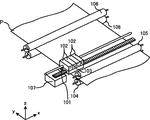
図1は本発明の代表的な実施例であるインクジェット記録ヘッド(以下、記録ヘッド)を用いて記録を行う記録装置の外観斜視図である。
<Overview of recording apparatus (FIG. 1)>
FIG. 1 is an external perspective view of a recording apparatus that performs recording using an ink jet recording head (hereinafter referred to as a recording head) that is a typical embodiment of the present invention.
図1に示されるように、記録ヘッド101はキャリッジ103に搭載され、記録ヘッド101にはブラック(K)、シアン(C)、マゼンタ(M)、イエロ(Y)計4色のインクタンク102から個別にインクが供給される。各インクタンク102は個別に交換可能であり、インクタンク102内部の負圧発生機構により、インクを保持している。ユーザがインクタンク102を交換する際には、インクタンクにアクセス可能な記録装置の開口部に備えられたカバー(不図示)を開くと、ユーザがインクタンクを交換可能な状態となる。
As shown in FIG. 1, the
キャリッジ103はキャリッジモータ(不図示)により主走査方向(図中のx方向)に往復移動する。図1において、Pは記録媒体を表し、キャリッジ103の主走査方向への走査と記録ヘッド101によるインク液滴の吐出により、1走査幅分の記録を完了する。1走査幅分の記録が完了すると、搬送ローラ104とピンチローラ105に挟持された記録媒体Pは搬送モータ(不図示)による搬送ローラ104の回転によって図中のy方向(副走査方向)へと搬送される。
The
また、記録媒体Pはその搬送方向下流側(図中のy方向側)で対になった排紙ローラ106よって挟持され、搬送ローラ104とピンチローラ105との挟持部との間で張力を発生させている。キャリッジ103の主走査方向の走査と記録ヘッド101からのインク液滴吐出と搬送ローラ104による記録媒体の搬送によって記録装置は1頁分の記録を完了する。
The recording medium P is sandwiched by a pair of
なお、キャリッジ103の移動範囲で記録領域の外側にはメンテナンスユニット(回復ユニット)107が設けられている。メンテナンスユニット107はワイピング機構、吸引機構から構成されている。
A maintenance unit (recovery unit) 107 is provided outside the recording area in the movement range of the
<キャリッジ周辺の詳細な構成(図2)
図2は図1に示した記録装置2のキャリッジ周辺の構成を示す記録装置2の部分的な前面図及び側断面図である。
<Detailed configuration around the carriage (FIG. 2)
2 is a partial front view and a side sectional view of the recording apparatus 2 showing the configuration around the carriage of the recording apparatus 2 shown in FIG.
図2において、(a)は図1のy方向から見た記録ヘッド101と回復ユニット107の構成を模式的に示した前面図であり、(b)は図1のx方向から見た記録ヘッド101と回復ユニット107の構成を模式的に示した側断面図である。
2A is a front view schematically showing the configuration of the
図2(a)と図2(b)に示す状態は、記録ヘッド101は、KCMYのインク各色に対応したノズル列を有するノズル面(インク吐出面)がキャップ201によってキャッピングされた状態である。この記録ヘッドは各色、1列のノズル列を有している構成となっている。キャップ201は駆動機構(不図示)によって上下(z方向)への移動が可能であり、キャップ201によりノズル面のキャッピングとキャップオープン動作を行う。
The state shown in FIGS. 2A and 2B is a state in which the
また、キャップ201の底面には、吸引ポンプ202へと繋がる吸引口203が備えられている。回復ユニット107により記録ヘッドの吸引動作を行う場合は、キャップ201によりノズル面のキャッピングを行い、吸引ポンプ202を動作させ、キャップ201内に負圧を発生させることにより、ノズル内のインクを吸引する。
In addition, a
また、図2(b)に示すように、回復ユニット107にはワイピング機構として記録ヘッド101のノズル面の汚れの清掃を拭きとるワイパ204を備え、ワイパ204によってノズル面のインク付着を拭き取る。ワイパ204は図2(b)においてy方向に駆動モータ(不図示)により移動することによって、ノズル面のインクを拭きとる。
As shown in FIG. 2B, the
インクタンク102はキャリッジ103に設けられた2箇所の爪部205によりキャリッジ103と係合し、矢印zとは反対方向に付勢されている。このような付勢により、インクタンク102のスポンジからなるインク供給部206は記録ヘッド101のインク受容部207に圧接された状態となっている。
The
インクタンク102にはインクタンクの使用履歴等の情報が書き込まれたICチップ208が備えられている。ICチップ208がキャリッジ103に設置されたコンタクト部209と電気的に接触することにより、ICチップ208内の情報を記録装置が読み取ることが可能である。また、ICチップ208の情報をコンタクト部209を介して読み取ることによりインクタンクが装着されたことを検知でき(第1の検知)、インクタンク検知センサとしての機能も果たす。
The
<制御構成の説明(図3)>
次に、図1を用いて説明した記録装置の記録制御を実行するための制御構成について説明する。
<Description of control configuration (FIG. 3)>
Next, a control configuration for executing recording control of the recording apparatus described with reference to FIG. 1 will be described.
図3は図1に示した記録装置の制御構成を示すブロック図である。 FIG. 3 is a block diagram showing a control configuration of the recording apparatus shown in FIG.
図3において、CPU300はメインバスライン305を介して装置各部の制御とデータ処理を実行する。即ち、CPU300は、ROM301に格納されたプログラムを実行して、データ処理、記録ヘッドの駆動制御、およびキャリッジ駆動制御を以下の各部を介して実行し、画像の記録を行わせる。CPU300はインタフェース310を介して、ホスト装置との通信処理が可能である。
In FIG. 3, a
RAM302はCPU300によるデータ処理等の作業領域として用いられ、一時的に記録ヘッドの複数走査記録分の記録データや記録装置の吸引処理動作及びインク供給動作に係るパラメータ等を保存する。画像入力部303はホスト装置からのインタフェース310を介して受信入力した画像データを一時的に保持する。
A
回復系制御回路308ではRAM302に格納される回復処理プログラムに従って回復系モータ309の駆動制御を行い、キャップ201の上下動作、ワイパ204の動作、及び吸引ポンプ202の動作等の吸引動作を制御する。ヘッド駆動制御回路304は、記録ヘッド101の駆動を制御し、通常は、予備吐出や記録のためのインク吐出を記録ヘッド101に行わせる。キャリッジ駆動回路307は、画像信号処理部314で処理された記録データに従った記録動作のために記録ヘッド101の走査を制御するとともに、吸引動作を行うために回復ユニットへの移動を制御する。
The recovery
インクタンク検知センサ313はインクタンクが装着されているか否かを検知可能なセンサであり、この実施例ではインクタンクに装着されたICチップを電気的に検知することにより装着の有無を検知する。なお、インクタンク検知センサは電気的にインクタンクを検知するものに限らず、メカニカルスイッチや光学センサを用いてもよい。
The ink
カバー検知センサ316は記録装置のカバーの開閉状態を検知する(第2の検知)センサであり、インクタンク検知センサと同様に、電気的なコンタクト、メカニカルスイッチ、光学的なセンサ等いずれのセンサを用いてもよい。
The
ソフトパワースイッチ317記録装置の制御回路に通電する電源のON/OFFを制御するスイッチであり、ユーザに操作によりOFFされると、ソフトパワースイッチの制御に関わる制御回路以外の制御回路の通電をOFFする。 Soft power switch 317 A switch for controlling ON / OFF of a power supply for supplying power to the control circuit of the recording apparatus. When the power is turned OFF by a user operation, the control circuit other than the control circuit related to the control of the soft power switch is turned off. To do.
図4はインクタンクが未装着の場合のキャリッジの上面図である。 FIG. 4 is a top view of the carriage when the ink tank is not attached.
図4は、インクタンク未装着状態でのキャリッジ103を図1に示したz方向の側から見た模式図である。図4に示されるように、インクタンクからのインクはインク受容部207に設けられたフィルタ(フィルタ部材)401を介して記録ヘッドへ流入する。フィルタ401は、ステンレス鋼繊維などの金属材料を焼結させたフィルタであり、10μm以上の不純物(異物)を捕集できる能力がある。
FIG. 4 is a schematic view of the
図4から分かるように、インク受容部207に設置されたフィルタ401は各色インクタンク毎のインク受容部に設置され、不純物が取り除かれ、異物の進入が阻止されたインクが記録ヘッドへと流入する。
As can be seen from FIG. 4, the
図5はインクタンク未装着状態でのフィルタの構造を模式的に示す側断面図である。図5において、(a)はインクタンクが外された直後のフィルタの側断面図であり、(b)はインクタンクが外され長時間経過した後のフィルタの側断面図である。 FIG. 5 is a side sectional view schematically showing the structure of the filter when the ink tank is not attached. 5A is a side sectional view of the filter immediately after the ink tank is removed, and FIG. 5B is a side sectional view of the filter after the ink tank has been removed and a long time has passed.
これらの図において、501は不織布状に焼結された状態のステンレス鋼繊維、502はフィルタに含浸したインク、503はタンクが外された状態で、大気とインク502との界面に発生したメニスカスである。
In these figures,
図5(a)に示されるように、インクタンクが外されると、フィルタ401に含浸されたインク502と空気との界面にメニスカスが生じる。また、インクタンクからの負圧が無くなる為、フィルタ401から記録ヘッド101までのインクは自重で下方へと力が係り、メニスカス503は記録ヘッドの方向へ凹状態となる。フィルタ401に生じたメニスカス503によりフィルタ401から記録ヘッド101までのインクは漏れることなく保持されている。
As shown in FIG. 5A, when the ink tank is removed, a meniscus is generated at the interface between the
しかしながら、そのままインクタンクが長時間外されたままの状態にあると、メニスカス503から揮発成分の蒸発が進んでしまう。図5(b)に示されるように、インクタンクが長時間外されると、揮発成分の蒸発によってインク体積が縮小し、メニスカスが後退する。その結果、フィルタ401よりも記録ヘッド101の側(図では下方)にメニスカスが後退するが、ステンレス繊維の隙間には毛管力によって残ったインク504の粘度が増し、固着してしまう。これにより、フィルタ401の目詰まりが生じる。フィルタ401に目詰まりが生じると、インクタンクからのインク供給量が低下し、インクの吐出が正常に行えなくなり吐出不良が発生する。そのため、このようなフィルタ401の目詰まりが生じないように制御が行われている。このようなフィルタ401の目詰まりは、顔料インクの場合に特に発生しやすいことが分かっているため、以下に示す目詰まりが生じないように制御を行うことが特に望ましいといえる。
However, if the ink tank remains removed for a long time, evaporation of volatile components from the
次に、このようなフィルタ401で目詰まりが発生しないような制御処理についてのいくつかの実施例を説明する。
Next, several examples of control processing that prevents clogging from occurring in such a
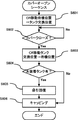
図6は実施例1に従う制御処理を示すフローチャートである。 FIG. 6 is a flowchart showing a control process according to the first embodiment.
図6によれば、インクタンク交換時のカバーオープンシーケンスを開始すると、まず、ステップS601では記録装置はカバーが開かれたことを、カバー検知センサによって検知する。非記録時にキャリッジ(CR)103は回復ユニット107の待機位置に位置しており、カバーオープン検知を行うと、キャリッジ103はユーザがインクタンクにアクセス可能な位置であるタンク交換位置に移動する。その後、カバーが閉じられるまでインクタンクは交換可能な状態である。
According to FIG. 6, when the cover open sequence at the time of ink tank replacement is started, first, in step S601, the recording apparatus detects that the cover is opened by the cover detection sensor. The carriage (CR) 103 is located at the standby position of the
次に、ステップS602では、カバーが閉じられたかどうかをカバー検知センサによって調べ、カバーが閉じられたことを検知すれば、そのタイミングで処理はステップS603に進む。ステップS603では、キャリッジ103は再び待機位置へと戻る。ステップS601〜S603のキャリッジの移動制御はCPU300によりキャリッジ駆動制御回路307を通してなされる。
Next, in step S602, whether or not the cover is closed is checked by a cover detection sensor. If it is detected that the cover is closed, the process proceeds to step S603 at that timing. In step S603, the
ステップS604では、記録装置はインクタンク検知センサによって、全てのインクタンクが装着されたかどうかを調べる。ここで、全てのインクタンクが装着されていると判断すれば、処理はステップS606に進み、一つでも装着されていないインクタンクがあると判断されれば、処理はステップS605に進む。 In step S604, the printing apparatus checks whether or not all ink tanks have been installed by the ink tank detection sensor. If it is determined that all the ink tanks are installed, the process proceeds to step S606. If it is determined that there is any ink tank that is not installed, the process proceeds to step S605.
ステップS605では、未装着インクタンクがあり、インクを含浸したフィルタ401が大気に晒されている状態であるため、記録装置は吸引ポンプ202を動作させ、記録ヘッド101のノズルからインクの吸引動作を行う。記録ヘッド101よりインクが吸引されると、フィルタに含浸されたインクをほぼ抜きとられるので、フィルタ401に残ったインクは微量であり、これが仮に蒸発、粘度が増しても、吐出不良の原因を生じさせる程、フィルタが目詰まりすることはない。
In step S605, since there is an unmounted ink tank and the
ステップS606では、記録ヘッドの保護の為、記録ヘッド101のキャッピングを行い、その後、処理を終了する。
In step S606, the
従って以上説明した実施例によれば、未装着インクタンクがある場合は記録ヘッドの吸引動作を行って、フィルタに含浸したインクを抜きとるので、フィルタの目詰まりを抑制し、吐出不良による記録画像の品質の低下を防止することができる。 Therefore, according to the above-described embodiment, when there is an unmounted ink tank, the suction operation of the recording head is performed to remove the ink impregnated in the filter. The deterioration of quality can be prevented.
なお、図6のステップ604では記録装置に一つでも装着されていないインクタンクがあると判断されれば、記録ヘッド101のノズルからインクの吸引動作を実行して、フィルタ401に残ったインクを吸引する例を示した。しかしながら、記録装置に装着される複数のインクタンクの全てが未装着のときに、記録ヘッド101のノズルからインクの吸引動作を実行するように制御してもよい。
If it is determined in step 604 of FIG. 6 that there is an ink tank that is not attached to the recording apparatus, the ink suction operation is executed from the nozzles of the
実施例1に従う構成では、KCMYインクを吐出する全てのノズル列を1つのキャップでキャッピングしていた為、1色でもインクタンクが未装着の状態があると、他の色のインクも吸引されてしまい、必要以上にインクを消費する場合があった。このような不利益を改善するために、実施例2では回復ユニット107に複数のキャップを備え、未装着のインクタンクに対応したキャップのみ吸引動作を実行する。
In the configuration according to the first embodiment, since all the nozzle rows that discharge KCMY ink are capped with one cap, if there is a state where an ink tank is not attached even with one color, ink of other colors is also sucked. As a result, the ink may be consumed more than necessary. In order to improve such a disadvantage, in the second embodiment, the
図7は実施例2に従う記録ヘッドと回復ユニットの構成を模式的に示す図である。 FIG. 7 is a diagram schematically illustrating the configuration of a recording head and a recovery unit according to the second embodiment.
なお、図7において、既に図2を用いて説明したのと同じ構成要素には同じ参照番号をふし、その説明は省略する。 In FIG. 7, the same components as those already described with reference to FIG. 2 are denoted by the same reference numerals, and the description thereof is omitted.
図7に示されるように、キャップA701により記録ヘッド101のKインクとCインクを吐出する2つのノズル列がキャップ可能であり、キャップB702により、記録ヘッド101のMインクとYインクを吐出する2つのノズル列をキャップする。キャップA701とキャップB702には夫々、吸引ポンプA703と吸引ポンプB704が繋がっており、吸引ポンプA703と吸引ポンプB704は独立に吸引動作が可能である。
As shown in FIG. 7, the
図8は実施例2に従う制御処理を示すフローチャートである。 FIG. 8 is a flowchart showing a control process according to the second embodiment.
なお、図8において、既に実施例1において説明したのと同じ処理については同じステップ参照番号を付し、その説明は省略する。 In FIG. 8, the same steps as those already described in the first embodiment are denoted by the same step reference numerals, and the description thereof is omitted.
ステップS604において、未装着のインクタンクがあると判断された場合、処理はステップS605Aにおいて、未装着タンクの種類をインクタンク検知センサを用いて調べる。 If it is determined in step S604 that there is an unmounted ink tank, the process checks the type of unmounted tank using an ink tank detection sensor in step S605A.
その結果、未装着のインクタンクがキャップAに対応したKインクを収容したインクタンクとCインクを収容したインクタンクとの内の少なくともいずれかであり、キャップBに対応したインクタンクでなければ処理はステップS605Bに進む。ステップS605Bでは、キャップA701に対応したフィルタが大気に晒されている状態であるため、記録装置は吸引ポンプA703のみを動作させ、記録ヘッド101のキャップA701に対応したノズルからインクの吸引動作を行う。その結果、キャップA701に対応したフィルタに含浸されたインクをほぼ抜きとられる。一方、キャップB702に対応したフィルタはインクタンクが装着されているため、フィルタに含浸されたインクの蒸発や粘度の増大は発生しない。
As a result, the unattached ink tank is at least one of the ink tank containing K ink corresponding to the cap A and the ink tank containing C ink, and if it is not the ink tank corresponding to the cap B, the processing is performed. Advances to step S605B. In step S605B, since the filter corresponding to the cap A701 is exposed to the atmosphere, the recording apparatus operates only the suction pump A703 and performs the ink suction operation from the nozzle corresponding to the cap A701 of the
また、未装着のインクタンクがキャップBに対応したMインクを収容したインクタンクとYインクを収容したインクタンクとの内の少なくともいずれかであり、キャップAに対応したインクタンクでなければ処理はステップS605Cに進む。ステップS605Cでは、キャップB702に対応した吸引ポンプB704のみを動作させ、記録ヘッド101のキャップB702に対応したノズルからインクの吸引動作を行う。
In addition, if the ink tank that has not been installed is at least one of an ink tank containing M ink corresponding to cap B and an ink tank containing Y ink, and if it is not an ink tank corresponding to cap A, processing is performed. The process proceeds to step S605C. In step S605C, only the suction pump B704 corresponding to the cap B702 is operated, and the ink is sucked from the nozzle corresponding to the cap B702 of the
またさらに、未装着のインクタンクがキャップAとキャップBの両方に対応したインクを収容するインクタンクであれば、処理はステップS605Dに進む。ステップS605Dでは、両方のキャップに対応したインクタンクが装着されていない為、キャップAとキャップB夫々に対応した吸引ポンプA703と吸引ポンプB704の両方を動作させて記録ヘッド101の吸引動作を行う。
Furthermore, if the unmounted ink tank is an ink tank that accommodates ink corresponding to both cap A and cap B, the process proceeds to step S605D. In step S605D, since the ink tanks corresponding to both caps are not mounted, both the suction pump A703 and the suction pump B704 corresponding to the cap A and the cap B are operated to perform the suction operation of the
従って以上説明した実施例に従えば、未装着のインクタンクに対応したキャップのみから吸引動作を実行するので、吸引処理によって不必要にインクが消費されることなく、フィルタに含浸したインクを抜きとることができる。これにより、実施例1と同様にフィルタの目詰まりを抑制し、吐出不良による記録画像の品質の低下を防止することができる。 Therefore, according to the embodiment described above, since the suction operation is executed only from the cap corresponding to the unmounted ink tank, the ink impregnated in the filter is extracted without unnecessary consumption of the ink by the suction processing. be able to. Accordingly, the clogging of the filter can be suppressed as in the first embodiment, and the deterioration of the quality of the recorded image due to the ejection failure can be prevented.
実施例1〜2では記録装置のカバー操作時に未装着インクタンクの検知を行い、吸引動作を行っていた。この場合、ユーザがインクタンク装着の意思はあるが、一時的にカバークローズをしてしまった場合でも、吸引動作が実行されてしまう。このような状況に対処するため、実施例3ではカバークローズ時ではなく、記録装置のソフトパワーOFF時に未装着インクタンクがあれば、吸引動作を実行する。 In Examples 1 and 2, an unmounted ink tank is detected and a suction operation is performed when a cover of the recording apparatus is operated. In this case, the user intends to install the ink tank, but the suction operation is executed even if the cover is temporarily closed. In order to cope with such a situation, in the third embodiment, if there is an unmounted ink tank at the time of soft power OFF of the printing apparatus, not when the cover is closed, a suction operation is executed.
実施例3に用いる記録ヘッドと回復ユニットは実施例1で説明したのと同様の構成である。 The recording head and the recovery unit used in the third embodiment have the same configuration as that described in the first embodiment.
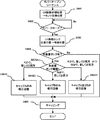
図9〜図10は、実施例3に従う制御処理を示すフローチャートである。 9 to 10 are flowcharts illustrating the control process according to the third embodiment.
図9はカバー操作時における未装着インクタンクの検知処理を示すフローチャートであり、図10はソフトパワーOFF時における吸引動作を示すフローチャートである。 FIG. 9 is a flowchart showing a detection process of an unmounted ink tank at the time of a cover operation, and FIG. 10 is a flowchart showing a suction operation at the time of soft power OFF.
なお、図9において、既に実施例1において説明したのと同じ処理については同じステップ参照番号を付し、その説明は省略する。 In FIG. 9, the same steps as those already described in the first embodiment are denoted by the same step reference numerals, and the description thereof is omitted.
ステップS604において、未装着インクタンクが有ると判断された場合、処理はステップS605Eにおいて、吸引動作を実行するのではなく、記録装置のRAM302にインク排出フラグをONとして格納する。これに対して、ステップS604において、未装着インクタンクが無と判断された場合、処理はステップS605Fにおいて、インク排出フラグをOFFにしてRAM302に格納する。
If it is determined in step S604 that there is an unmounted ink tank, the process does not execute the suction operation in step S605E, but stores the ink discharge flag in the
これにより、一度ユーザがインクタンク未装着状態でカバーをクローズし、ソフトパワーOFF操作を行う前に未装着のインクタンクを装着すれば、フィルタの大気曝露(露出)は短期間だと判断する。そして、フィルタからのインク排出動作である吸引動作を不要とできる。 As a result, once the user closes the cover with no ink tank attached, and installs an unattached ink tank before performing the soft power OFF operation, it is determined that the atmospheric exposure (exposure) of the filter is short. And the suction operation which is the ink discharge operation from the filter can be made unnecessary.
次に、図10を参照して、ソフトパワーOFF時における吸引動作について説明する。 Next, with reference to FIG. 10, the suction operation when the soft power is OFF will be described.
ユーザにより記録装置のソフトパワースイッチがソフトパワーOFFに操作されると、ステップS911においてキャリッジ103は待機位置へと移動する。
When the user operates the soft power switch of the recording apparatus to turn off the soft power, the
次に、ステップS912では、記録装置のRAM302に格納されているインク排出フラグがONであるかOFFであるかを調べる。ここで、インク排出フラグがONであれば処理はステップS913に進み、OFFであれば処理はステップS915に進む。
Next, in step S912, it is checked whether the ink discharge flag stored in the
インク排出フラグがONであれば未装着インクタンクがあり、インクを含浸したフィルタが大気に晒されている状態にある。このままユーザがソフトパワーOFFを行うと、長時間、記録装置が使用されず、フィルタが大気に晒されている状態が長時間に及ぶ可能性が高い。そのため、ステップS913では、記録装置は吸引ポンプを動作させ、記録ヘッド101のノズルからインクの吸引動作を実行する。この吸引動作により、実施例1〜2と同様、フィルタに残ったインクが微量であるため、仮にこれが蒸発、粘度が増しても吐出不良を生じさせる程のフィルタの目詰まりにはならない。
If the ink discharge flag is ON, there is an unmounted ink tank, and the filter impregnated with ink is exposed to the atmosphere. If the user turns off the soft power as it is, there is a high possibility that the recording apparatus is not used for a long time and the filter is exposed to the atmosphere for a long time. Therefore, in step S <b> 913, the recording apparatus operates the suction pump to execute an ink suction operation from the nozzles of the
ステップS915では、キャッピングを行い、処理を終了する。 In step S915, capping is performed and the process ends.
従って以上説明した実施例に従えば、カバーオープンシーケンスではたとえ未装着インクタンクがあることが認識されても、その状態を記憶したままで直ぐに吸引は実行せず、ソフトパワーOFF時に未装着インクタンクがあれば吸引動作を実行する。これにより、不必要な吸引処理によってインクを消費することなく、より効果的にフィルタに含浸したインクを抜きとることができる。また、実施例1〜2と同様に、フィルタの目詰まりを抑制し、吐出不良による記録画像の品質の低下を防止することができる。 Therefore, according to the embodiment described above, even if it is recognized that there is an uninstalled ink tank in the cover open sequence, the suction is not performed immediately while the state is stored, and the uninstalled ink tank is not turned on when the soft power is turned off. If there is, perform the suction operation. Thereby, the ink impregnated in the filter can be extracted more effectively without consuming ink by unnecessary suction processing. Further, similarly to the first and second embodiments, the clogging of the filter can be suppressed, and the deterioration of the recorded image quality due to the ejection failure can be prevented.
Claims (16)
前記記録ヘッドへ供給されるインクを収容し、前記キャリッジに装着可能なインクタンクと、
前記キャリッジに配され前記インクタンクが装着されたときに当該インクタンクと当接するフィルタ部材と、
前記キャリッジに対する前記インクタンクの装着の有無を検知する検知手段と、
前記複数のノズル列からインクを吸引する吸引手段と、を備える記録装置であって、
開閉可能な、前記記録装置のカバーと、
前記カバーの開閉状態を検知するカバー検知手段と、
前記検知手段により前記インクタンクが前記キャリッジに装着されていないことが検知された場合は、前記記録装置のメモリに格納されたインクの吸引を指示するフラグをONにし、前記インクタンクが前記キャリッジに装着されていることが検知された場合は、前記フラグをOFFにする制御手段と、をさらに備え、
前記制御手段は、前記カバー検知手段により前記カバーの閉状態が検知されたタイミングで前記検知手段に前記インクタンクの装着の有無を検知させて、前記記録装置がソフトパワーOFFの操作が行われたタイミングにおいて、前記フラグがONの場合は前記吸引手段による吸引動作を行わせ、該タイミングにおいて前記フラグがOFFの場合は前記吸引手段による吸引動作を行わせないことを特徴とする記録装置。 A carriage for mounting a recording head in which a plurality of Roh nozzle row is provided for ejecting ink,
An ink tank that contains ink to be supplied to the recording head and is mountable on the carriage ;
A filter member disposed on the carriage and in contact with the ink tank when the ink tank is mounted ;
Detection means for detecting the presence or absence of the mounting of the ink tank to the previous SL carriage,
A recording apparatus comprising a suction means for sucking the ink from the previous SL plurality of nozzle rows, a,
A cover of the recording device that can be opened and closed;
Cover detection means for detecting the open / closed state of the cover;
When the detection unit detects that the ink tank is not mounted on the carriage , the flag for instructing the suction of ink stored in the memory of the recording apparatus is turned ON, and the ink tank is attached to the carriage . And a control means for turning off the flag when it is detected that it is attached ,
The control unit causes the detection unit to detect whether or not the ink tank is mounted at a timing when the cover detection unit detects the closed state of the cover, and the recording apparatus is operated to turn off the soft power. The recording apparatus according to claim 1 , wherein when the flag is ON, the suction operation by the suction unit is performed, and when the flag is OFF at the timing, the suction operation by the suction unit is not performed .
開閉可能な、前記記録装置のカバーの開閉状態を検知する第1の工程と、
前記第1の工程において前記カバーの閉状態が検知されたタイミングで前記インクタンクが前記キャリッジに装着されていないことが検知された場合は、前記記録装置のメモリに格納されたインクの吸引を指示するフラグをONにし、該タイミングで前記インクタンクが前記キャリッジに装着されていることが検知された場合は、前記フラグをOFFにする第2の工程と、
前記記録装置がソフトパワーOFFの操作が行われたタイミングにおいて、前記フラグがONの場合は前記吸引手段による吸引動作を行わせ、該タイミングにおいて前記フラグがOFFの場合は前記吸引手段による吸引動作を行わせない第3の工程と、を有することを特徴とする記録装置の制御方法。 A carriage for mounting a recording head in which a plurality of nozzle rows are provided for ejecting ink, an ink tank attachable to the ink accommodating the carriage to be supplied to the recording head, the ink tank arranged on the carriage A filter member that comes into contact with the ink tank when mounted; a detecting unit that detects whether the ink tank is mounted on the carriage; and a suction unit that sucks ink from the plurality of nozzle rows. A recording apparatus control method comprising:
A first step of detecting an open / closed state of the cover of the recording apparatus that can be opened and closed ;
If it is detected that the ink tank is not attached to the carriage at the timing when the cover is closed in the first step, the ink suction instruction stored in the memory of the recording apparatus is instructed. A second step of turning off the flag when it is detected that the ink tank is mounted on the carriage at the timing ;
If the flag is on at the timing when the soft power OFF operation is performed on the recording apparatus, the suction operation is performed by the suction unit. If the flag is OFF at the timing, the suction operation by the suction unit is performed. And a third step that is not performed .
Priority Applications (2)
| Application Number | Priority Date | Filing Date | Title |
|---|---|---|---|
| JP2013080840A JP6222965B2 (en) | 2012-05-07 | 2013-04-08 | Recording apparatus and recording apparatus control method |
| US13/864,614 US8944562B2 (en) | 2012-05-07 | 2013-04-17 | Printing apparatus and control method therefor |
Applications Claiming Priority (3)
| Application Number | Priority Date | Filing Date | Title |
|---|---|---|---|
| JP2012106318 | 2012-05-07 | ||
| JP2012106318 | 2012-05-07 | ||
| JP2013080840A JP6222965B2 (en) | 2012-05-07 | 2013-04-08 | Recording apparatus and recording apparatus control method |
Publications (3)
| Publication Number | Publication Date |
|---|---|
| JP2013252696A JP2013252696A (en) | 2013-12-19 |
| JP2013252696A5 JP2013252696A5 (en) | 2016-05-26 |
| JP6222965B2 true JP6222965B2 (en) | 2017-11-01 |
Family
ID=49512217
Family Applications (1)
| Application Number | Title | Priority Date | Filing Date |
|---|---|---|---|
| JP2013080840A Active JP6222965B2 (en) | 2012-05-07 | 2013-04-08 | Recording apparatus and recording apparatus control method |
Country Status (2)
| Country | Link |
|---|---|
| US (1) | US8944562B2 (en) |
| JP (1) | JP6222965B2 (en) |
Families Citing this family (11)
| Publication number | Priority date | Publication date | Assignee | Title |
|---|---|---|---|---|
| JP5984790B2 (en) * | 2013-12-18 | 2016-09-06 | キヤノン株式会社 | Information processing apparatus, control method for information processing apparatus, storage medium, and program |
| JP6938252B2 (en) | 2017-07-07 | 2021-09-22 | キヤノン株式会社 | Liquid discharge device |
| JP6921662B2 (en) | 2017-07-07 | 2021-08-18 | キヤノン株式会社 | Inkjet recording device |
| JP6904819B2 (en) | 2017-07-07 | 2021-07-21 | キヤノン株式会社 | Inkjet recording device and control method |
| JP2019034547A (en) | 2017-08-10 | 2019-03-07 | キヤノン株式会社 | Ink jet recording apparatus and detection method |
| JP6559857B1 (en) * | 2018-08-24 | 2019-08-14 | 紀州技研工業株式会社 | Filter device |
| JP7166869B2 (en) | 2018-10-05 | 2022-11-08 | キヤノン株式会社 | Recording device and recording method |
| JP7207930B2 (en) | 2018-10-05 | 2023-01-18 | キヤノン株式会社 | Inkjet recording device and recovery method |
| JP7224835B2 (en) | 2018-10-05 | 2023-02-20 | キヤノン株式会社 | Recording device and judgment method |
| JP7250467B2 (en) | 2018-10-05 | 2023-04-03 | キヤノン株式会社 | Inkjet recording device and control method |
| JP7350506B2 (en) | 2019-04-25 | 2023-09-26 | キヤノン株式会社 | Recording device, its control method, and program |
Family Cites Families (27)
| Publication number | Priority date | Publication date | Assignee | Title |
|---|---|---|---|---|
| GB2112715B (en) * | 1981-09-30 | 1985-07-31 | Shinshu Seiki Kk | Ink jet recording apparatus |
| JP2954225B2 (en) | 1989-01-28 | 1999-09-27 | キヤノン株式会社 | Ink tank |
| US5488401A (en) * | 1991-01-18 | 1996-01-30 | Seiko Epson Corporation | Ink-jet recording apparatus and ink tank cartridge thereof |
| JP3101381B2 (en) * | 1991-12-19 | 2000-10-23 | キヤノン株式会社 | Ink jet recording apparatus and recovery method therefor |
| PT1219446E (en) * | 1993-07-20 | 2005-06-30 | Canon Kk | An ink jet recording apparatus which uses the recording unit with ink cartridge having an element which includes ink |
| JP3201122B2 (en) * | 1994-02-08 | 2001-08-20 | 富士通株式会社 | Inkjet printer |
| JP3387691B2 (en) * | 1994-05-19 | 2003-03-17 | キヤノン株式会社 | Ink jet apparatus and method of operating the same |
| US6447095B1 (en) * | 1994-05-19 | 2002-09-10 | Canon Kabushiki Kaisha | Discharge recovery method for ink jet apparatus using waterproof ink and ink jet apparatus employing the method |
| JPH0911492A (en) * | 1995-06-30 | 1997-01-14 | Canon Inc | Ink jet recorder |
| US5997121A (en) * | 1995-12-14 | 1999-12-07 | Xerox Corporation | Sensing system for detecting presence of an ink container and level of ink therein |
| JP2939872B2 (en) * | 1996-04-23 | 1999-08-25 | 富士ゼロックス株式会社 | Recording device and ink tank |
| DE69938285T2 (en) | 1998-12-15 | 2009-03-12 | Canon K.K. | inkjet |
| JP2001334684A (en) * | 2000-05-25 | 2001-12-04 | Mutoh Ind Ltd | Ink jet printer |
| JP4944296B2 (en) | 2000-11-01 | 2012-05-30 | キヤノン株式会社 | Ink jet recording apparatus and discharge recovery method |
| JP4086590B2 (en) | 2002-08-28 | 2008-05-14 | キヤノン株式会社 | Recording apparatus and preliminary discharge control method |
| JP4266599B2 (en) | 2002-08-29 | 2009-05-20 | キヤノン株式会社 | Ink jet recording apparatus and preliminary ejection control method for the apparatus |
| JP2004090233A (en) | 2002-08-29 | 2004-03-25 | Canon Inc | Inkjet recorder |
| JP3950770B2 (en) | 2002-09-12 | 2007-08-01 | キヤノン株式会社 | Ink jet recording apparatus and preliminary discharge method |
| JP2004174884A (en) * | 2002-11-27 | 2004-06-24 | Canon Inc | Recording device and method of determining ink tank remaining quantity |
| JP4037278B2 (en) * | 2003-01-29 | 2008-01-23 | シャープ株式会社 | Image forming apparatus |
| CN100368199C (en) | 2004-02-12 | 2008-02-13 | 佳能株式会社 | Liquid applying apparatus and ink jet printing apparatus |
| US7556339B2 (en) | 2004-02-12 | 2009-07-07 | Canon Kabushiki Kaisha | Ink jet printing apparatus |
| JP4498148B2 (en) | 2004-02-12 | 2010-07-07 | キヤノン株式会社 | Liquid applicator, recording device |
| JP4816378B2 (en) * | 2006-09-29 | 2011-11-16 | ブラザー工業株式会社 | Ink cartridge and inkjet recording system |
| JP4941487B2 (en) * | 2009-03-16 | 2012-05-30 | ブラザー工業株式会社 | Droplet discharge device |
| JP5310394B2 (en) * | 2009-08-31 | 2013-10-09 | ブラザー工業株式会社 | Liquid ejection device |
| JP5724406B2 (en) | 2010-03-16 | 2015-05-27 | 株式会社リコー | Image forming apparatus |
-
2013
- 2013-04-08 JP JP2013080840A patent/JP6222965B2/en active Active
- 2013-04-17 US US13/864,614 patent/US8944562B2/en active Active
Also Published As
| Publication number | Publication date |
|---|---|
| US8944562B2 (en) | 2015-02-03 |
| JP2013252696A (en) | 2013-12-19 |
| US20130293631A1 (en) | 2013-11-07 |
Similar Documents
| Publication | Publication Date | Title |
|---|---|---|
| JP6222965B2 (en) | Recording apparatus and recording apparatus control method | |
| JP4989361B2 (en) | Maintenance device, liquid ejection device, and nozzle surface maintenance method | |
| JP4914627B2 (en) | Discharge recovery device for liquid discharge head and image forming apparatus having the same | |
| JP4948146B2 (en) | Inkjet recording device | |
| JP3838251B2 (en) | Inkjet recording apparatus and ejection failure detection method | |
| JP3952054B2 (en) | Image forming apparatus | |
| JP6597650B2 (en) | Inkjet recording device | |
| JP2013252697A (en) | Recording device and control method for the same | |
| JP2007261088A (en) | Liquid discharge apparatus and maintenance method of liquid discharge head | |
| JP3909714B2 (en) | Ink jet recording apparatus and preliminary discharge control method | |
| JP5526624B2 (en) | Image printing apparatus and image printing method | |
| US7240983B2 (en) | Inkjet recording apparatus and preliminary discharge control method | |
| JP2010000671A (en) | Ink cartridge and image forming device | |
| JP2007223146A (en) | Liquid discharge head and image forming apparatus equipped with the same | |
| JP3992215B2 (en) | Ink jet recording apparatus and recovery system cleaning method thereof | |
| JP4258732B2 (en) | Image forming apparatus | |
| JP3823991B2 (en) | Ink jet recording apparatus and preliminary discharge control method | |
| JP2004050472A (en) | Inkjet recorder | |
| JP2004066810A (en) | Method of detecting ejection of liquid and image forming apparatus | |
| JP3865135B2 (en) | Image forming apparatus | |
| JP2000246922A (en) | Recorder, facsimile employing it and ejection recovery method for recorder | |
| JP2009061756A (en) | Inkjet recording apparatus and its control method | |
| JP2005205850A (en) | Deaerator, liquid discharge device and inkjet recorder | |
| JP2004074605A (en) | Inkjet recorder | |
| US10836172B2 (en) | Recording head and ink-jet recording apparatus therewith |
Legal Events
| Date | Code | Title | Description |
|---|---|---|---|
| A521 | Written amendment |
Free format text: JAPANESE INTERMEDIATE CODE: A523 Effective date: 20160329 |
|
| A621 | Written request for application examination |
Free format text: JAPANESE INTERMEDIATE CODE: A621 Effective date: 20160329 |
|
| A977 | Report on retrieval |
Free format text: JAPANESE INTERMEDIATE CODE: A971007 Effective date: 20170227 |
|
| A131 | Notification of reasons for refusal |
Free format text: JAPANESE INTERMEDIATE CODE: A131 Effective date: 20170303 |
|
| A521 | Written amendment |
Free format text: JAPANESE INTERMEDIATE CODE: A523 Effective date: 20170501 |
|
| TRDD | Decision of grant or rejection written | ||
| A01 | Written decision to grant a patent or to grant a registration (utility model) |
Free format text: JAPANESE INTERMEDIATE CODE: A01 Effective date: 20170904 |
|
| A61 | First payment of annual fees (during grant procedure) |
Free format text: JAPANESE INTERMEDIATE CODE: A61 Effective date: 20171003 |
|
| R151 | Written notification of patent or utility model registration |
Ref document number: 6222965 Country of ref document: JP Free format text: JAPANESE INTERMEDIATE CODE: R151 |