JP6217023B2 - 差動装置及びその製造方法 - Google Patents
差動装置及びその製造方法 Download PDFInfo
- Publication number
- JP6217023B2 JP6217023B2 JP2013271808A JP2013271808A JP6217023B2 JP 6217023 B2 JP6217023 B2 JP 6217023B2 JP 2013271808 A JP2013271808 A JP 2013271808A JP 2013271808 A JP2013271808 A JP 2013271808A JP 6217023 B2 JP6217023 B2 JP 6217023B2
- Authority
- JP
- Japan
- Prior art keywords
- welding
- flange
- ring gear
- differential
- press
- Prior art date
- Legal status (The legal status is an assumption and is not a legal conclusion. Google has not performed a legal analysis and makes no representation as to the accuracy of the status listed.)
- Expired - Fee Related
Links
Images

Classifications
-
- F—MECHANICAL ENGINEERING; LIGHTING; HEATING; WEAPONS; BLASTING
- F16—ENGINEERING ELEMENTS AND UNITS; GENERAL MEASURES FOR PRODUCING AND MAINTAINING EFFECTIVE FUNCTIONING OF MACHINES OR INSTALLATIONS; THERMAL INSULATION IN GENERAL
- F16H—GEARING
- F16H48/00—Differential gearings
- F16H48/38—Constructional details
- F16H48/40—Constructional details characterised by features of the rotating cases
-
- B—PERFORMING OPERATIONS; TRANSPORTING
- B23—MACHINE TOOLS; METAL-WORKING NOT OTHERWISE PROVIDED FOR
- B23K—SOLDERING OR UNSOLDERING; WELDING; CLADDING OR PLATING BY SOLDERING OR WELDING; CUTTING BY APPLYING HEAT LOCALLY, e.g. FLAME CUTTING; WORKING BY LASER BEAM
- B23K31/00—Processes relevant to this subclass, specially adapted for particular articles or purposes, but not covered by any single one of main groups B23K1/00 - B23K28/00
- B23K31/02—Processes relevant to this subclass, specially adapted for particular articles or purposes, but not covered by any single one of main groups B23K1/00 - B23K28/00 relating to soldering or welding
-
- B—PERFORMING OPERATIONS; TRANSPORTING
- B23—MACHINE TOOLS; METAL-WORKING NOT OTHERWISE PROVIDED FOR
- B23K—SOLDERING OR UNSOLDERING; WELDING; CLADDING OR PLATING BY SOLDERING OR WELDING; CUTTING BY APPLYING HEAT LOCALLY, e.g. FLAME CUTTING; WORKING BY LASER BEAM
- B23K2101/00—Articles made by soldering, welding or cutting
- B23K2101/008—Gears
-
- F—MECHANICAL ENGINEERING; LIGHTING; HEATING; WEAPONS; BLASTING
- F16—ENGINEERING ELEMENTS AND UNITS; GENERAL MEASURES FOR PRODUCING AND MAINTAINING EFFECTIVE FUNCTIONING OF MACHINES OR INSTALLATIONS; THERMAL INSULATION IN GENERAL
- F16H—GEARING
- F16H48/00—Differential gearings
- F16H48/38—Constructional details
- F16H2048/382—Methods for manufacturing differential gearings
-
- F—MECHANICAL ENGINEERING; LIGHTING; HEATING; WEAPONS; BLASTING
- F16—ENGINEERING ELEMENTS AND UNITS; GENERAL MEASURES FOR PRODUCING AND MAINTAINING EFFECTIVE FUNCTIONING OF MACHINES OR INSTALLATIONS; THERMAL INSULATION IN GENERAL
- F16H—GEARING
- F16H48/00—Differential gearings
- F16H48/38—Constructional details
- F16H2048/385—Constructional details of the ring or crown gear
-
- F—MECHANICAL ENGINEERING; LIGHTING; HEATING; WEAPONS; BLASTING
- F16—ENGINEERING ELEMENTS AND UNITS; GENERAL MEASURES FOR PRODUCING AND MAINTAINING EFFECTIVE FUNCTIONING OF MACHINES OR INSTALLATIONS; THERMAL INSULATION IN GENERAL
- F16H—GEARING
- F16H48/00—Differential gearings
- F16H48/06—Differential gearings with gears having orbital motion
- F16H48/08—Differential gearings with gears having orbital motion comprising bevel gears
Landscapes
- Engineering & Computer Science (AREA)
- General Engineering & Computer Science (AREA)
- Mechanical Engineering (AREA)
- Retarders (AREA)
- General Details Of Gearings (AREA)
- Laser Beam Processing (AREA)
- Gears, Cams (AREA)
Description
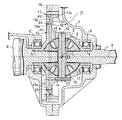
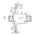
H1・・・厚肉部での溶接深さ
H2・・・薄肉部での溶接深さ
P1・・・フランジの軸方向の中央位置で構成される面
P2・・・リングギヤのスポークの軸方向の中央位置で構成される面
X・・・・軸線
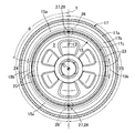
θ・・・・間隔
1・・・・ミッションケース
2・・・・デフケース
3・・・・デフ機構
4・・・・第1軸受ボス
5・・・・第2軸受ボス
6,6′・軸受
9・・・・ピニオン軸
13・・・・ピン孔
14・・・・抜け止めピン
15・・・・フランジ
15a・・・厚肉部
15b・・・薄肉部
17・・・・リンクギヤ
17a・・・リム
17b・・・スポーク
17c・・・ハブ
18・・・・作業窓
19・・・・凹部
22・・・・圧入規制手段(ストッパ壁)
23・・・・溶接
24,25・・・分割領域
27・・・・溶接開始点
28・・・・溶接終了点
Claims (7)
- デフ機構(3)を収容するデフケース(2)の一側部及び他側部に,同一軸線(X)上に並んでそれぞれミッションケース(1)に軸受(6,6′)を介して支持される第1及び第2軸受ボス(4 ,5 )を一体に形成し,また同デフケース(2)の中心(C)から前記第2軸受ボス(5)側にオフセットした中間部に環状のフランジ(15)を一体に形成し,さらに同デフケース(2)の,前記軸線(X)と直交する一直径線上で対向する周壁に,前記デフ機構(3)を挿入するための作業窓(18)を設け,これら作業窓(18)が前記フランジ(15)に食い込むことで,前記フランジ(15)の,前記第1軸受ボス(4)側の側面に凹部(19)が形成され,前記フランジ(15)の外周面にリングギヤ(17)を圧入嵌合して,これらフランジ(15)及びリングギヤ(17)の圧入嵌合部を溶接した差動装置であって,
前記フランジ(15)及びリングギヤ(17)の圧入嵌合部に,これらフランジ(15)及びリングギヤ(17)の圧入深さを規制する圧入規制手段(22)を設け,前記フランジ(15)は,前記凹部(19)が存在する薄肉部(15b)と,前記凹部(19)が存在しない厚肉部(15a)とを有し,その厚肉部(15a)と前記リングギヤ(17)とに,前記第2軸受ボス(5)側から所定の溶接深さ(H1)をもって溶接(23)を施し,また薄肉部(15b)と前記リングギヤ(17)とには,前記第2軸受ボス(5)側から前記所定の溶接深さ(H1)よりも浅い溶接深さ(H2)をもって溶接(23)を施し,もしくは溶接を施さないことを特徴とする差動装置。 - 請求項1に記載の差動装置において,
前記フランジ(15)及びリングギヤ(17)の圧入嵌合部の溶接開始点(27)及び溶接終了点(28)を前記厚肉部(15a)で一致させたことを特徴とする差動装置。 - 請求項2に記載の差動装置において,
前記フランジ(15)及びリングギヤ(17)の圧入嵌合部を,周方向に並ぶ複数の分割領域(24,25)に等分し,各分割領域(24,25)の溶接開始点(27)と,それに隣接する分割領域の溶接終了点(28)とを前記厚肉部(15a)で一致させたことを特徴とする差動装置。 - 請求項2又は3に記載の差動装置において,
一致する前記溶接開始点(27)及び溶接終了点(28)と前記薄肉部(15b)との間隔(θ)を,前記フランジ(15)の中心軸線周りで45°以上に設定したことを特徴とする差動装置。 - 請求項1〜4の何れかに記載の差動装置において,
前記デフ機構(3)のピニオン軸(9)の抜け止めピン(14)が嵌挿されるピン孔(13)を,これが前記デフケース(2)の外周部を貫通するように設け,このピン孔(13)を基準にして前記溶接開始点(27)を設定したことを特徴とする差動装置。 - 請求項1〜5の何れかに記載の差動装置において,
前記リングギヤ(17)を,外周に歯部を有するリム(17a)と,このリム(17a)に囲繞されて前記フランジ(15)に圧入嵌合されるハブ(17c)と,これらリム(17a)及びハブ(17c)間を一体に連結するスポーク(17b)とで構成し,そのスポーク(17b)の軸方向の中央位置で構成される面(P2)を,前記フランジ(15)の軸方向の中央位置で構成される面(P1)よりも前記第1軸受ボス(4)側に配置したことを特徴とする差動装置。 - 請求項1記載の差動装置の製造方法において,
前記薄肉部(15b)と前記リングギヤ(17)とに溶接(23)を施す際には,溶接出力を厚肉部(15a)の場合に比して低減するか,溶接速度を厚肉部(15a)の場合に比して速くすることを特徴とする差動装置の製造方法。
Priority Applications (4)
| Application Number | Priority Date | Filing Date | Title |
|---|---|---|---|
| JP2013271808A JP6217023B2 (ja) | 2013-12-27 | 2013-12-27 | 差動装置及びその製造方法 |
| DE102014226643.2A DE102014226643A1 (de) | 2013-12-27 | 2014-12-19 | Differentialvorrichtung und Verfahren zum Herstellen derselben |
| US14/578,797 US9476493B2 (en) | 2013-12-27 | 2014-12-22 | Differential device and method of manufacturing the same |
| CN201410809366.3A CN104747681A (zh) | 2013-12-27 | 2014-12-23 | 差动装置及其制造方法 |
Applications Claiming Priority (1)
| Application Number | Priority Date | Filing Date | Title |
|---|---|---|---|
| JP2013271808A JP6217023B2 (ja) | 2013-12-27 | 2013-12-27 | 差動装置及びその製造方法 |
Publications (3)
| Publication Number | Publication Date |
|---|---|
| JP2015124874A JP2015124874A (ja) | 2015-07-06 |
| JP2015124874A5 JP2015124874A5 (ja) | 2016-08-12 |
| JP6217023B2 true JP6217023B2 (ja) | 2017-10-25 |
Family
ID=53372313
Family Applications (1)
| Application Number | Title | Priority Date | Filing Date |
|---|---|---|---|
| JP2013271808A Expired - Fee Related JP6217023B2 (ja) | 2013-12-27 | 2013-12-27 | 差動装置及びその製造方法 |
Country Status (4)
| Country | Link |
|---|---|
| US (1) | US9476493B2 (ja) |
| JP (1) | JP6217023B2 (ja) |
| CN (1) | CN104747681A (ja) |
| DE (1) | DE102014226643A1 (ja) |
Families Citing this family (13)
| Publication number | Priority date | Publication date | Assignee | Title |
|---|---|---|---|---|
| JP6501584B2 (ja) | 2015-03-30 | 2019-04-17 | 武蔵精密工業株式会社 | 伝動装置 |
| US20170152930A1 (en) * | 2015-11-30 | 2017-06-01 | Ford Global Technologies, Llc | Precisely aligned, friction welded spiral bevel or hypoid ring gear and differential case assembly |
| JP6335983B2 (ja) * | 2016-08-08 | 2018-05-30 | 株式会社Subaru | 差動装置の製造方法及び差動装置 |
| US11231099B2 (en) * | 2016-11-09 | 2022-01-25 | Arvinmeritor Technology, Llc | Axle assembly and differential assembly with spider shaft retention |
| JP6876592B2 (ja) * | 2017-10-30 | 2021-05-26 | 武蔵精密工業株式会社 | 差動装置 |
| JP6847874B2 (ja) * | 2018-01-18 | 2021-03-24 | 武蔵精密工業株式会社 | 差動装置 |
| JP2019152266A (ja) * | 2018-03-02 | 2019-09-12 | 本田技研工業株式会社 | ディファレンシャル装置 |
| US11213917B2 (en) * | 2018-11-13 | 2022-01-04 | GM Global Technology Operations LLC | Fusion welding of ferrous alloy component parts using low carbon steel band |
| JP2020159443A (ja) * | 2019-03-26 | 2020-10-01 | 武蔵精密工業株式会社 | 差動装置 |
| JP7251380B2 (ja) * | 2019-07-24 | 2023-04-04 | スズキ株式会社 | 自動車用差動装置 |
| DE112020007778T5 (de) * | 2020-11-17 | 2024-02-15 | Musashi Seimitsu Industry Co., Ltd. | Differentialvorrichtung |
| US11873888B1 (en) * | 2022-11-18 | 2024-01-16 | GM Global Technology Operations LLC | Differential carrier and ring gear assembly |
| CN118951306B (zh) * | 2024-09-12 | 2025-09-05 | 泰州凡羽精密齿轮制造有限公司 | 一种齿轮激光焊接夹具 |
Family Cites Families (19)
| Publication number | Priority date | Publication date | Assignee | Title |
|---|---|---|---|---|
| US2529392A (en) * | 1947-12-23 | 1950-11-07 | Chrysler Corp | Support for rear axle differentials |
| DE10013429C5 (de) * | 2000-03-17 | 2009-10-01 | Daimler Ag | Ausgleichgetriebe |
| JP2003001490A (ja) | 2001-06-13 | 2003-01-08 | Denso Corp | 突合わせ溶接方法 |
| JP4686982B2 (ja) * | 2004-01-30 | 2011-05-25 | トヨタ自動車株式会社 | 差動装置 |
| JP2007010040A (ja) | 2005-06-30 | 2007-01-18 | Musashi Seimitsu Ind Co Ltd | デファレンシャル装置 |
| US20090266198A1 (en) * | 2008-04-29 | 2009-10-29 | Transform Automotive Llc | Laser welded differential casings for vehicle axles |
| JP2010032018A (ja) * | 2008-07-30 | 2010-02-12 | Gkn ドライブライン トルクテクノロジー株式会社 | デフ・ケース及びその加工方法、デファレンシャル装置 |
| JP4858513B2 (ja) * | 2008-08-22 | 2012-01-18 | トヨタ自動車株式会社 | 差動装置の接合方法、及び接合補助具 |
| JP5520494B2 (ja) * | 2009-02-06 | 2014-06-11 | Gknドライブラインジャパン株式会社 | デファレンシャル装置 |
| JP5332937B2 (ja) | 2009-06-19 | 2013-11-06 | トヨタ自動車株式会社 | 部材間の溶接方法 |
| DE102009045424A1 (de) * | 2009-10-07 | 2011-04-14 | Zf Friedrichshafen Ag | Achsdifferenzial eines Kraftfahrzeuges und Verfahren zur Montage eines Achsdifferenzial |
| JP5359813B2 (ja) | 2009-11-24 | 2013-12-04 | トヨタ自動車株式会社 | 車両用デファレンシャル切替装置 |
| JP5697344B2 (ja) * | 2010-02-15 | 2015-04-08 | トヨタ自動車株式会社 | 差動装置 |
| JP2011161506A (ja) * | 2010-02-15 | 2011-08-25 | Toyota Motor Corp | 溶接方法 |
| JP5509910B2 (ja) | 2010-02-22 | 2014-06-04 | 日産自動車株式会社 | ビーム溶接部材およびこれを備えた差動装置 |
| JP5327130B2 (ja) | 2010-04-23 | 2013-10-30 | トヨタ自動車株式会社 | リングギヤの溶接方法及び溶接構造 |
| CN102179658B (zh) * | 2011-02-28 | 2015-05-20 | 深圳市骏腾发自动焊接装备股份有限公司 | 一种汽车制动器齿轮圈焊接方法以及使用该方法的装置 |
| JP5687577B2 (ja) * | 2011-07-12 | 2015-03-18 | トヨタ自動車株式会社 | 溶接構造、及び溶接方法 |
| CN103732348B (zh) | 2011-08-04 | 2016-03-09 | 丰田自动车株式会社 | 焊接结构及焊接结构的制造方法 |
-
2013
- 2013-12-27 JP JP2013271808A patent/JP6217023B2/ja not_active Expired - Fee Related
-
2014
- 2014-12-19 DE DE102014226643.2A patent/DE102014226643A1/de not_active Ceased
- 2014-12-22 US US14/578,797 patent/US9476493B2/en not_active Expired - Fee Related
- 2014-12-23 CN CN201410809366.3A patent/CN104747681A/zh active Pending
Also Published As
| Publication number | Publication date |
|---|---|
| JP2015124874A (ja) | 2015-07-06 |
| CN104747681A (zh) | 2015-07-01 |
| US9476493B2 (en) | 2016-10-25 |
| US20150184735A1 (en) | 2015-07-02 |
| DE102014226643A1 (de) | 2015-07-02 |
Similar Documents
| Publication | Publication Date | Title |
|---|---|---|
| JP6217023B2 (ja) | 差動装置及びその製造方法 | |
| JP2015124874A5 (ja) | ||
| JP6189745B2 (ja) | 差動装置の製造方法 | |
| JP6196271B2 (ja) | 溶接構造及び溶接構造の製造方法 | |
| JP5293840B2 (ja) | 溶接構造および溶接構造の製造方法 | |
| JP5206656B2 (ja) | 車両用差動歯車装置 | |
| JPWO2015080133A1 (ja) | 流体継手の製造方法及び流体継手 | |
| US10415682B2 (en) | Differential case | |
| JP2019082204A (ja) | 差動装置 | |
| US9156110B2 (en) | Weldment with isolation pocket for reduction of weld-induced distortion | |
| JP6457031B2 (ja) | 差動装置 | |
| JP2010281419A (ja) | ドライブプレート | |
| JP6187280B2 (ja) | 差動歯車装置及びその製造方法 | |
| JP2017198238A (ja) | デファレンシャルギヤケース | |
| JP6734800B2 (ja) | デフケースとリングギヤの溶接構造 | |
| JP6467268B2 (ja) | 遊星歯車機構 | |
| WO2019044502A1 (ja) | ディファレンシャル装置の製造方法 | |
| JP2008208935A (ja) | トリポート型等速ジョイント | |
| US12372147B2 (en) | Differential cage | |
| JP2007292171A (ja) | 等速自在継手の外側継手部材製造方法 | |
| JP2019168077A (ja) | 差動歯車装置 | |
| JP5833412B2 (ja) | 電子ビーム溶接方法 | |
| JP5511570B2 (ja) | ビスカス・カップリング、第1回転部材、及び加工方法 | |
| JP2016011690A (ja) | トルクコンバータ用ハブスプラインの製造方法 |
Legal Events
| Date | Code | Title | Description |
|---|---|---|---|
| A521 | Request for written amendment filed |
Free format text: JAPANESE INTERMEDIATE CODE: A523 Effective date: 20160624 |
|
| A621 | Written request for application examination |
Free format text: JAPANESE INTERMEDIATE CODE: A621 Effective date: 20160624 |
|
| A131 | Notification of reasons for refusal |
Free format text: JAPANESE INTERMEDIATE CODE: A131 Effective date: 20170607 |
|
| A521 | Request for written amendment filed |
Free format text: JAPANESE INTERMEDIATE CODE: A523 Effective date: 20170705 |
|
| TRDD | Decision of grant or rejection written | ||
| A01 | Written decision to grant a patent or to grant a registration (utility model) |
Free format text: JAPANESE INTERMEDIATE CODE: A01 Effective date: 20170830 |
|
| A61 | First payment of annual fees (during grant procedure) |
Free format text: JAPANESE INTERMEDIATE CODE: A61 Effective date: 20170907 |
|
| R150 | Certificate of patent or registration of utility model |
Ref document number: 6217023 Country of ref document: JP Free format text: JAPANESE INTERMEDIATE CODE: R150 |
|
| R250 | Receipt of annual fees |
Free format text: JAPANESE INTERMEDIATE CODE: R250 |
|
| R250 | Receipt of annual fees |
Free format text: JAPANESE INTERMEDIATE CODE: R250 |
|
| R250 | Receipt of annual fees |
Free format text: JAPANESE INTERMEDIATE CODE: R250 |
|
| LAPS | Cancellation because of no payment of annual fees |