JP6214877B2 - Radioactive material distribution map creation system and radioactive material distribution map creation method - Google Patents
Radioactive material distribution map creation system and radioactive material distribution map creation method Download PDFInfo
- Publication number
- JP6214877B2 JP6214877B2 JP2013013672A JP2013013672A JP6214877B2 JP 6214877 B2 JP6214877 B2 JP 6214877B2 JP 2013013672 A JP2013013672 A JP 2013013672A JP 2013013672 A JP2013013672 A JP 2013013672A JP 6214877 B2 JP6214877 B2 JP 6214877B2
- Authority
- JP
- Japan
- Prior art keywords
- distribution map
- radiation
- radioactive substance
- map creation
- data
- Prior art date
- Legal status (The legal status is an assumption and is not a legal conclusion. Google has not performed a legal analysis and makes no representation as to the accuracy of the status listed.)
- Active
Links
Images


Classifications
-
- G—PHYSICS
- G06—COMPUTING; CALCULATING OR COUNTING
- G06T—IMAGE DATA PROCESSING OR GENERATION, IN GENERAL
- G06T11/00—2D [Two Dimensional] image generation
- G06T11/60—Editing figures and text; Combining figures or text
-
- G—PHYSICS
- G01—MEASURING; TESTING
- G01T—MEASUREMENT OF NUCLEAR OR X-RADIATION
- G01T7/00—Details of radiation-measuring instruments
-
- G—PHYSICS
- G01—MEASURING; TESTING
- G01T—MEASUREMENT OF NUCLEAR OR X-RADIATION
- G01T1/00—Measuring X-radiation, gamma radiation, corpuscular radiation, or cosmic radiation
- G01T1/16—Measuring radiation intensity
- G01T1/167—Measuring radioactive content of objects, e.g. contamination
-
- G—PHYSICS
- G06—COMPUTING; CALCULATING OR COUNTING
- G06T—IMAGE DATA PROCESSING OR GENERATION, IN GENERAL
- G06T11/00—2D [Two Dimensional] image generation
- G06T11/20—Drawing from basic elements, e.g. lines or circles
- G06T11/206—Drawing of charts or graphs
Landscapes
- Physics & Mathematics (AREA)
- General Physics & Mathematics (AREA)
- Health & Medical Sciences (AREA)
- Life Sciences & Earth Sciences (AREA)
- High Energy & Nuclear Physics (AREA)
- Molecular Biology (AREA)
- Spectroscopy & Molecular Physics (AREA)
- Engineering & Computer Science (AREA)
- Theoretical Computer Science (AREA)
- Measurement Of Radiation (AREA)
Description
本発明は、放射性物質の分布マップを作成するための技術に関する。 The present invention relates to a technique for creating a distribution map of radioactive materials.
放射性物質の測定を行う放射線検出器として、様々なものが知られている。ガイガーカウンタは、最も原始的な放射線検出器である。また、ピンホールカメラの原理を応用した放射線検出器も知られている。そのようなピンホールカメラ方式の放射線検出器の場合、測定範囲がある程度広く(視野角=約60度、測定可能距離=十数m)、その測定範囲内の放射性物質の分布を一回で測定することができる。 Various radiation detectors for measuring radioactive substances are known. The Geiger counter is the most primitive radiation detector. A radiation detector using the principle of a pinhole camera is also known. In the case of such a pinhole camera type radiation detector, the measurement range is wide to some extent (viewing angle = approximately 60 degrees, measurable distance = tens of meters), and the distribution of radioactive substances within the measurement range is measured at a time. can do.
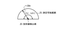
本願の出願人は、ピンホールカメラ方式よりも更に高性能な「コンプトンカメラ」の開発を行っている(例えば、特許文献1、特許文献2を参照)。このコンプトンカメラは、ガンマ線が粒子の性質を持つことによるコンプトン散乱の原理を応用している。コンプトンカメラの場合、視野角は180度(厳密には立体角で2πステラジアン)と広く、また、測定可能距離も約30mと長い。つまり、コンプトンカメラの測定範囲は、他の方式の場合よりもはるかに広い。また、コンプトンカメラは、放射線のエネルギーも測定しており、そのエネルギー測定データに基づいて放射性物質の種類(核種)を識別することも可能である。 The applicant of the present application has developed a “Compton camera” having higher performance than the pinhole camera system (see, for example, Patent Document 1 and Patent Document 2). This Compton camera applies the principle of Compton scattering due to the nature of gamma rays as particles. In the case of a Compton camera, the viewing angle is as wide as 180 degrees (strictly, the solid angle is 2π steradians), and the measurable distance is as long as about 30 m. In other words, the measurement range of the Compton camera is much wider than in other methods. The Compton camera also measures the energy of radiation and can also identify the type (nuclide) of the radioactive material based on the energy measurement data.
原子力発電所で事故が発生した場合等、広範囲(例えば、数ヘクタールの範囲)における放射性物質の分布マップが必要とされる場合がある。しかしながら、従来、広範囲の放射性物質の分布マップを迅速に作成する手法は提案されていなかった。 In some cases, such as when an accident occurs at a nuclear power plant, a distribution map of radioactive material over a wide area (for example, a range of several hectares) may be required. However, conventionally, a method for quickly creating a distribution map of a wide range of radioactive materials has not been proposed.
本発明の1つの目的は、広範囲の放射性物質の分布マップを迅速に作成することができる技術を提供することにある。 One object of the present invention is to provide a technique capable of quickly creating a distribution map of a wide range of radioactive substances.
以下に、[発明を実施するための最良の形態]で使用される番号・符号を用いて、[課題を解決するための手段]を説明する。これらの番号・符号は、[特許請求の範囲]の記載と[発明を実施するための最良の形態]との対応関係を明らかにするために括弧付きで付加されたものである。ただし、それらの番号・符号を、[特許請求の範囲]に記載されている発明の技術的範囲の解釈に用いてはならない。 [Means for Solving the Problems] will be described below using the numbers and symbols used in [Best Mode for Carrying Out the Invention]. These numbers and symbols are added in parentheses in order to clarify the correspondence between the description of [Claims] and [Best Mode for Carrying Out the Invention]. However, these numbers and symbols should not be used for the interpretation of the technical scope of the invention described in [Claims].
本発明の1つの観点において、放射性物質分布マップ作成システム(1)が提供される。その放射性物質分布マップ作成システム(1)は、放射線検出器(20)と、位置測定器(30)と、放射性物質分布マップ作成装置(100)とを備える。放射線検出器(20)は、移動体(10)に搭載され、放射性物質の測定を行う。位置測定器(30)は、その移動体(10)の位置を測定する。放射性物質分布マップ作成装置(100)は、放射線検出器(20)による測定結果(NUC)と位置測定器(30)によって測定された移動体(10)の位置情報(POS)とを含む測定データ(MSR)を受け取る。そして、放射性物質分布マップ作成装置(100)は、移動体(10)の移動に伴って得られる複数位置での測定データ(MSR)を用いることによって、放射性物質の分布マップ(DTB)を作成する。 In one aspect of the present invention, a radioactive substance distribution map creation system (1) is provided. The radioactive substance distribution map creation system (1) includes a radiation detector (20), a position measuring device (30), and a radioactive substance distribution map creation device (100). The radiation detector (20) is mounted on the moving body (10) and measures a radioactive substance. The position measuring device (30) measures the position of the moving body (10). The radioactive substance distribution map creation device (100) includes measurement data including a measurement result (NUC) by the radiation detector (20) and position information (POS) of the moving body (10) measured by the position measurement device (30). (MSR) is received. The radioactive substance distribution map creation device (100) creates a radioactive substance distribution map (DTB) by using measurement data (MSR) at a plurality of positions obtained with the movement of the moving body (10). .
本発明の他の観点において、放射性物質分布マップ作成方法が提供される。その放射性物質分布マップ作成方法は、[A]移動体(10)に搭載された放射線検出器(20)を用いて放射性物質の測定を行うステップと、[B]その移動体(10)の位置を測定するステップと、を含む。ここで、測定データ(MSR)は、放射線検出器(20)による測定結果(NUC)と移動体(10)の位置情報(POS)とを含む。放射性物質分布マップ作成方法は、更に、[C]移動体(10)の移動に伴って得られる複数位置での測定データ(MSR)を用いることによって、放射性物質の分布マップ(DTB)を作成するステップを含む。 In another aspect of the present invention, a method for creating a radioactive substance distribution map is provided. The radioactive substance distribution map creation method includes [A] a step of measuring a radioactive substance using a radiation detector (20) mounted on a moving body (10), and [B] a position of the moving body (10). Measuring. Here, the measurement data (MSR) includes a measurement result (NUC) by the radiation detector (20) and position information (POS) of the moving body (10). The radioactive material distribution map creation method further creates a distribution map (DTB) of radioactive material by using [C] measurement data (MSR) at a plurality of positions obtained with the movement of the moving body (10). Includes steps.
本発明によれば、広範囲の放射性物質の分布マップを迅速に作成することが可能となる。 According to the present invention, it is possible to quickly create a distribution map of a wide range of radioactive substances.
添付図面を参照して、本発明の実施の形態を説明する。 Embodiments of the present invention will be described with reference to the accompanying drawings.
1.放射性物質分布マップ作成システムの概要
図1は、本実施の形態に係る放射性物質分布マップ作成システム1の概要を示す概念図である。放射性物質分布マップ作成システム1は、移動体10と放射性物質分布マップ作成装置100とを備えている。
1. Overview of Radioactive Material Distribution Map Creation System FIG. 1 is a conceptual diagram showing an overview of a radioactive material distribution map creation system 1 according to the present embodiment. The radioactive substance distribution map creating system 1 includes a moving body 10 and a radioactive substance distribution
移動体10としては、航空機、車両、船舶等が例示される。 Examples of the moving body 10 include an aircraft, a vehicle, and a ship.
移動体10には、放射性物質の測定を行う放射線検出器20が搭載されている。放射線検出器20としては、高感度で且つ測定範囲の広いコンプトンカメラが例示される(特許文献1、特許文献2参照)。コンプトンカメラの場合、図2に示されるように測定可能範囲25が非常に広く(視野角=2πステラジアン、測定可能距離=約30m)、好適である。但し、本実施の形態における放射線検出器20は、コンプトンカメラに限定されず、ピンホールカメラ方式の放射線検出器等であってもよい。いずれにせよ、移動体10の移動に伴い、放射線検出器20も移動し、放射線検出器20による測定可能範囲25も時間的に移り変わっていく。
The moving body 10 is equipped with a
放射性物質分布マップ作成装置100は、広範囲の放射性物質分布マップを作成するための装置であり、コンピュータにより実現される。この放射性物質分布マップ作成装置100は、放射線検出器20と共に移動体10に搭載されていてもよいし、移動体10とは別の場所に設置され、移動体10と通信可能に接続されていてもよい。あるいは、放射性物質分布マップ作成装置100は、放射線検出器20と一体的に構成されていてもよい。いずれにせよ、放射線物質分布マップ作成装置100は、放射線検出器20による測定結果に基づいて、放射性物質分布マップを作成する。
The radioactive substance distribution
より詳細には、放射線物質分布マップ作成装置100は、移動体10及び放射線検出器20から「測定データ」を受け取る。その測定データは、放射線検出器20による測定結果と移動体10の位置情報とを少なくとも含む。ここで、本実施の形態によれば、移動体10が移動するため、複数位置で測定データが得られる。よって、放射線物質分布マップ作成装置100は、移動体10の移動に伴って得られる複数位置での測定データを組み合わせることによって、放射性物質分布マップを作成することができる。
More specifically, the radiation material distribution
より詳細には、放射線物質分布マップ作成装置100は、放射線検出器20による測定結果に基づいて、放射線源の方向を算出する。上述の通り複数位置で測定データが得られるため、放射線源の方向も複数位置で算出され得る。よって、放射線物質分布マップ作成装置100は、複数位置で得られた放射線源方向に基づく“ステレオ視”により、放射線源の位置を正確に同定することができる。そして、放射線物質分布マップ作成装置100は、1以上の放射線源の位置を組み合わせることによって、放射線物質分布マップを作成する。
More specifically, the radiation material distribution
このような放射線物質分布マップ作成手法は、測定対象が放射線である場合に特有な次のような条件が満たされるからこそ実現されると言える:(1)放射線は放射線源から放射状に放出される、(2)放射線は遮蔽物を透過する、(3)放射線の放射状態が一定期間維持される(尚、半減期が数時間以上の放射性物質を対象としている)。上記の条件(1)、(2)が満たされるため、放射線源から離れた複数位置での測定データに基づくステレオ視により、放射線源の位置を正確に同定することができるのである。更に、条件(3)が満たされるため、複数位置から同じタイミングで同じ放射線源を観測する必要はなく、異なるタイミングで得られた測定データを組み合わせて用いることができるのである。つまり、本実施の形態の放射線物質分布マップ作成手法に複数台の放射線検出器20は不要であり、1台の放射線検出器20で十分である。
It can be said that such a radiation material distribution map creation method is realized because the following conditions specific to the case where the measurement object is radiation are satisfied: (1) Radiation is emitted radially from the radiation source. (2) The radiation passes through the shield. (3) The radiation state of the radiation is maintained for a certain period of time (in addition, the radioactive substance having a half-life of several hours or more is targeted). Since the above conditions (1) and (2) are satisfied, the position of the radiation source can be accurately identified by stereo vision based on measurement data at a plurality of positions distant from the radiation source. Furthermore, since the condition (3) is satisfied, it is not necessary to observe the same radiation source from a plurality of positions at the same timing, and measurement data obtained at different timings can be used in combination. That is, a plurality of
図3は、移動体10が航空機(例:無人ヘリ)である場合の測定例を示している。航空機がある領域を旋回移動することにより、航空機に搭載された放射線検出器20が当該領域の放射線を繰り返し測定する。重畳的に得られる測定データに基づいて、広範囲における放射性物質の3次元分布マップを迅速に作成することが可能である。
FIG. 3 shows a measurement example when the moving body 10 is an aircraft (eg, unmanned helicopter). As the aircraft turns around an area, the
図4は、移動体10が車両(例:自動車、鉄道)である場合の測定例を示している。車両が所定のルートに沿って移動することにより、車両に搭載された放射線検出器20が当該ルートの近傍領域の放射線を繰り返し測定する。重畳的に得られる測定データに基づいて、広範囲における放射性物質の3次元分布マップを迅速に作成することが可能である。
FIG. 4 shows a measurement example when the moving body 10 is a vehicle (eg, automobile, railway). As the vehicle moves along a predetermined route, the
以上に説明されたように、本実施の形態によれば、放射線検出器20が移動体10に搭載される。そして、移動体10の移動に伴って得られる複数位置での測定データを組み合わせることによって、広範囲の放射性物質分布マップが迅速に作成される。
As described above, according to the present embodiment, the
また、本実施の形態によれば、複数位置から同じタイミングで同じ放射線源を観測する必要はない。異なるタイミングで得られた測定データを組み合わせて用いることにより、放射性物質分布マップを作成することができる。よって、複数台の放射線検出器20は不要であり、1台の放射線検出器20で十分である。このことは、測定の容易性、柔軟性及びコストの観点から好適である。
Further, according to the present embodiment, it is not necessary to observe the same radiation source from a plurality of positions at the same timing. By using the measurement data obtained at different timings in combination, a radioactive substance distribution map can be created. Therefore, a plurality of
更に、異なるタイミングで得られる測定データを利用可能であることは、同じ領域に関する測定データを一定期間蓄積し、重畳的に得られた測定データを利用可能であることを意味する(図3、図4参照)。従って、高精度の放射性物質分布マップを作成することが可能である。例えば放射線量が少ない状況であっても、重畳的に得られた測定データを組み合わせることによって、正確な放射性物質分布マップを作成することができる。 Furthermore, the availability of measurement data obtained at different timings means that measurement data relating to the same region can be accumulated for a certain period and the measurement data obtained in a superimposed manner can be used (FIGS. 3 and 3). 4). Therefore, it is possible to create a highly accurate radioactive substance distribution map. For example, even in a situation where the radiation dose is small, an accurate radioactive substance distribution map can be created by combining measurement data obtained in a superimposed manner.
また、異なるタイミングで得られる測定データを利用可能であることは、時間的に連続して放射線の観測を行わなくてもよいことを意味する。従って、移動体10の搭乗者の被曝量を低減することができる。つまり、本実施の形態によれば、放射性物質分布マップを作成する際の安全性が向上する。 In addition, the availability of measurement data obtained at different timings means that it is not necessary to observe radiation continuously in time. Therefore, the exposure amount of the passenger of the moving body 10 can be reduced. That is, according to the present embodiment, safety when creating a radioactive substance distribution map is improved.
また、放射性物質の漏えい事故や秘密裡に行われるテロによる放射性物質の散布など、状況が急変する場合には、放射性物質の分布傾向が変わるため、いち早く事態を把握できる。 Also, if the situation suddenly changes, such as a radioactive material leakage accident or a secret terrorist attack, the distribution tendency of the radioactive material changes, so the situation can be quickly grasped.
放射線検出器20としては、高感度で且つ測定範囲の広いコンプトンカメラを利用することが好適である。これにより、1回の測定時間を短縮し、放射性物質分布マップの作成時間を短縮することができる。
As the
2.構成例
2−1.移動体10
図5は、本実施の形態における移動体10の構成例を示すブロック図である。移動体10には、放射線検出器20、位置測定器30、及び姿勢測定器40が搭載されている。
2. Configuration example 2-1. Mobile body 10
FIG. 5 is a block diagram showing a configuration example of the moving body 10 in the present embodiment. A
放射線検出器20は、放射性物質の測定を行う。放射線検出器20としては、高感度で且つ測定範囲の広いコンプトンカメラが例示される。また、コンプトンカメラは、放射線のエネルギーを測定することもできる。但し、本実施の形態における放射線検出器20は、コンプトンカメラに限定されず、ピンホールカメラ方式の放射線検出器等であってもよい。
The
位置測定器30は、移動体10の位置(例:緯度、経度、高度)を測定する。位置測定器30としては、GPS(Global Positioning System)が例示される。
The
姿勢測定器40は、放射線検出器20の姿勢角や角速度を測定する。姿勢測定器40としては、ジャイロセンサが例示される。
The
2−2.放射性物質分布マップ作成装置100
図6は、本実施の形態における放射性物質分布マップ作成装置100の構成例を示すブロック図である。放射性物質分布マップ作成装置100は、コンピュータであり、処理装置110、記憶装置120及び表示装置130を備えている。
2-2. Radioactive material distribution
FIG. 6 is a block diagram illustrating a configuration example of the radioactive substance distribution
処理装置110としては、CPUやマイクロコンピュータが例示される。この処理装置110は、機能ブロックとして、放射線信号処理部111、放射線源同定部112、放射線強度算出部113、核種分析部114、分布マップ生成部115、及び分布マップ表示部116を備えている。各機能ブロックは、処理装置110がプログラムPROGを実行することにより実現される。各機能ブロックによる処理の詳細は、後述される。
An example of the
記憶装置120としては、HDDやRAMが例示される。この記憶装置120には、積算データITG、放射性物質分布マップDTB、地図データMAPなどが格納される。詳細は後述される。また、記憶装置120には、処理装置110によって実行されるプログラムPROGも格納される。尚、プログラムPROGは、コンピュータ読み取り可能な記録媒体に記録されていてもよい。
Examples of the storage device 120 include an HDD and a RAM. The storage device 120 stores integration data ITG, radioactive substance distribution map DTB, map data MAP, and the like. Details will be described later. The storage device 120 also stores a program PROG that is executed by the
表示装置130としては、液晶ディスプレイが例示される。
An example of the
3.処理フロー
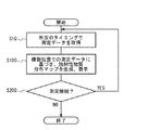
図7及び図8は、それぞれ、本実施形態に係る放射性物質分布マップ作成システム1による処理フローを示すブロック図及びフローチャートである。図7及び図8を参照して、本実施の形態に係る処理フローを説明する。
3. Processing Flow FIGS. 7 and 8 are a block diagram and a flowchart showing a processing flow by the radioactive substance distribution map creation system 1 according to this embodiment, respectively. A processing flow according to the present embodiment will be described with reference to FIGS.
ステップS10:
放射線検出器20は、放射性物質の測定を行い、その測定結果を示す放射線測定データNUCを生成する。放射線測定データNUCは、測定された放射線の強度(エネルギー)や、検出器上の検出位置などを示す。そして、放射線検出器20は、放射線測定データNUCを、放射性物質分布マップ作成装置100に出力する。
Step S10:
The
位置測定器30は、移動体10の位置を測定し、位置データPOSを生成する。位置データPOSは、例えば、移動体10(つまりは放射線検出器20)の緯度、経度、及び高度を示す。そして、位置測定器30は、位置データPOSを、放射性物質分布マップ作成装置100に出力する。
The
姿勢測定器40は、放射線検出器20の姿勢角や角速度を測定し、その測定結果を示す姿勢データATTを生成する。そして、姿勢測定器40は、姿勢データATTを、放射性物質分布マップ作成装置100に出力する。
The
測定データMSRは、上記の放射線測定データNUC、位置データPOS及び姿勢データATTを含んでいる。放射性物質分布マップ作成装置100は、その測定データMSRを受け取る。
The measurement data MSR includes the radiation measurement data NUC, the position data POS, and the attitude data ATT. The radioactive substance distribution
ステップS100:
放射線物質分布マップ作成装置100は、移動体10の移動に伴って得られる複数位置での測定データMSRを組み合わせることによって、放射性物質分布マップDTBを作成する。また、放射線物質分布マップ作成装置100は、作成した放射性物質分布マップDTBを、表示装置130に表示する。図9は、このステップS100における処理を示すフローチャートである。
Step S100:
The radioactive substance distribution
ステップS111:
放射線信号処理部111は、放射線検出器20によって得られた放射線測定データNUCに基づいて、放射線の飛来方向、すなわち、放射線源の方向を算出する。そして、放射線信号処理部111は、算出した放射線源の方向を示す放射線源方向データDIRを生成する。
Step S111:
The radiation
ステップS112:
放射線源同定部112は、放射線源方向データDIR、位置データPOS、及び姿勢データATTを受け取る。そして、放射線源同定部112は、放射線源方向データDIR、位置データPOS、及び姿勢データATTを関連付けて、積算データITGに登録する。この積算データITGは、測定の繰り返しにより蓄積されるデータのかたまりである。
Step S112:
The radiation
また、放射線源同定部112は、積算データITGに蓄積されている過去のデータを参照することにより、今回測定された放射線源の位置を同定する。例えば、複数位置で得られた放射線源方向データDIR、位置データPOS、及び姿勢データATTを組み合わせてステレオ視またはパターンマッチングすることにより、放射線源の位置を同定することができる。このようにして、放射線源同定部112は、放射線源の位置を同定し、その位置を示す放射線源位置データLOCを生成する。放射線源同定部112は、生成した放射線源位置データLOCも積算データITGに登録する。
The radiation
ステップS113:
放射線強度算出部113は、放射線源位置データLOCと放射線測定データNUCを受け取り、放射線源の位置と測定された放射線の強度(エネルギー)とを関連付けて、積算データITGに登録する。このとき、同じ放射線源位置に関する放射線強度が既に登録されている場合は、放射線強度を積算して登録する。つまり、放射線強度算出部113は、同定されたそれぞれの放射線源位置に関して測定された放射線強度を積算していく。そして、放射線強度算出部113は、積算放射線強度を示す放射線強度データINTを生成する。
Step S113:
The radiation
ステップS114:
核種分析部114は、観測された放射性物質の核種を判別する。具体的には、核種分析部114は、放射線強度データINTに基づいてエネルギースペクトルを作成し、既知の核種固有のエネルギーデータを参照して放射性物質の核種を判別する。そして、核種分析部114は、核種判別結果を示す核種分析データSPEを生成する。
Step S114:
The
ステップS115:
分布マップ生成部115は、積算データITGに登録されている放射線源位置データLOCを組み合わせて、放射性物質分布マップDTBを作成、更新する。このとき、分布マップ生成部115は、放射線強度データINTを参照して、それぞれの放射線源での放射線強度が分かるように放射性物質分布マップDTBを作成してもよい。また、分布マップ生成部115は、核種分析データSPEを参照して、核種毎に識別可能なように放射性物質分布マップDTBを作成してもよい。
Step S115:
The
ステップS116:
分布マップ表示部116は、作成された放射性物質分布マップDTBを表示装置130に表示する。放射性物質分布マップDTBが核種毎に識別可能なように作成されている場合、表示装置130においても、核種毎に識別可能なように放射性物質分布マップDTBは表示される。また、分布マップ表示部116は、国土地理院発行の地図を示す地図データMAPを読み出し、放射性物質分布マップDTBを地図に重ね合わせて表示してもよい。
Step S116:
The distribution
ステップS200:
再度図8を参照して、測定を継続する場合(ステップS200;Yes)、処理は上記のステップS10に戻る。測定を終了する場合(ステップS200;No)、処理は終了する。
Step S200:
Referring to FIG. 8 again, when the measurement is continued (step S200; Yes), the process returns to step S10. When the measurement is finished (step S200; No), the process is finished.
4.変形例
次に、本実施の形態の変形例を説明する。図10は、変形例における移動体10の構成例を示すブロック図である。図11は、変形例における処理フローを示すブロック図である。上述の説明と重複する説明は適宜省略する。
4). Modified Example Next, a modified example of the present embodiment will be described. FIG. 10 is a block diagram illustrating a configuration example of the moving body 10 according to the modification. FIG. 11 is a block diagram illustrating a processing flow in the modification. A description overlapping with the above description is omitted as appropriate.
本変形例では、移動体10に可視光カメラ50が更に搭載されている。可視光カメラ50は、可視光画像を撮像し、可視光画像データVISを生成する。放射性物質分布マップ作成装置100は、可視光画像データVISを受け取る。分布マップ表示部116は、可視光画像データVISと姿勢データATTを参照することにより、放射性物質分布マップDTBを可視光画像に重ね合わせて表示装置130に表示する。これにより、移動体10の視点でリアルタイムに可視光画像と重畳して放射性物質分布マップDTBを表示することができる。
In this modification, a
5.まとめ
以上に説明されたように、本実施の形態によれば、放射線検出器20が移動体10に搭載される。そして、移動体10の移動に伴って得られる複数位置での測定データMSRを組み合わせることによって、広範囲の放射性物質分布マップDTBが迅速に作成される。
5. Summary As described above, according to the present embodiment, the
また、本実施の形態によれば、複数位置から同じタイミングで同じ放射線源を観測する必要はない。異なるタイミングで得られた測定データMSRを組み合わせて用いることにより、放射性物質分布マップDTBを作成することができる。よって、複数台の放射線検出器20は不要であり、1台の放射線検出器20で十分である。このことは、測定の容易性、柔軟性及びコストの観点から好適である。
Further, according to the present embodiment, it is not necessary to observe the same radiation source from a plurality of positions at the same timing. By using the measurement data MSR obtained at different timings in combination, the radioactive substance distribution map DTB can be created. Therefore, a plurality of
更に、異なるタイミングで得られる測定データMSRを利用可能であることは、同じ領域に関する測定データMSRを一定期間蓄積し、重畳的に得られた測定データMSRを利用可能であることを意味する(図3、図4参照)。従って、高精度の放射性物質分布マップDTBを作成することが可能である。例えば放射線量が少ない状況であっても、重畳的に得られた測定データMSRを組み合わせることによって、正確な放射性物質分布マップDTBを作成することができる。 Furthermore, the availability of measurement data MSR obtained at different timings means that measurement data MSR relating to the same region can be accumulated for a certain period and the measurement data MSR obtained in a superimposed manner can be used (see FIG. 3, see FIG. Therefore, it is possible to create a highly accurate radioactive substance distribution map DTB. For example, an accurate radioactive substance distribution map DTB can be created by combining the measurement data MSR obtained in a superimposed manner even in a situation where the radiation dose is small.
また、異なるタイミングで得られる測定データMSRを利用可能であることは、時間的に連続して放射線の観測を行わなくてもよいことを意味する。従って、移動体10の搭乗者の被曝量を低減することができる。つまり、本実施の形態によれば、放射性物質分布マップDTBを作成する際の安全性が向上する。 In addition, the availability of measurement data MSR obtained at different timings means that it is not necessary to observe radiation continuously in time. Therefore, the exposure amount of the passenger of the moving body 10 can be reduced. That is, according to the present embodiment, safety when creating the radioactive substance distribution map DTB is improved.
また、放射性物質の漏えい事故や秘密裡に行われるテロによる放射性物質の散布など、状況が急変する場合には、放射性物質の分布傾向が変わるため、いち早く事態を把握できる。 Also, if the situation suddenly changes, such as a radioactive material leakage accident or a secret terrorist attack, the distribution tendency of the radioactive material changes, so the situation can be quickly grasped.
放射線検出器20としては、高感度で且つ測定範囲の広いコンプトンカメラを利用することが好適である。これにより、1回の測定時間を短縮し、放射性物質分布マップの作成時間を短縮することができる。
As the
本実施の形態に係る放射性物質分布マップ作成システム1は、原子力分野(原発事故などに伴う除染時の放射性物質可視化、原子力発電所内の放射線量モニタ、低レベル放射性廃棄物の放射線モニタ)、資源分野(自然起源放射性物質(NORM)のモニタ)、安全保障分野(テロなどによる隠ぺいされた放射性物質の探索、散布された放射性物質の分布マップ作成)等に適用可能である。 The radioactive material distribution map creation system 1 according to the present embodiment is applied to the nuclear field (radioactive material visualization at the time of decontamination associated with a nuclear accident, radiation dose monitor in a nuclear power plant, radiation monitor of low-level radioactive waste), resources It can be applied to fields (monitoring of naturally occurring radioactive materials (NORM)), security fields (searching for concealed radioactive materials due to terrorism, etc., creating distribution maps of scattered radioactive materials), and the like.
以上、本発明の実施の形態が添付の図面を参照することにより説明された。但し、本発明は、上述の実施の形態に限定されず、要旨を逸脱しない範囲で当業者により適宜変更され得る。 The embodiments of the present invention have been described above with reference to the accompanying drawings. However, the present invention is not limited to the above-described embodiments, and can be appropriately changed by those skilled in the art without departing from the scope of the invention.
1 放射性物質分布マップ作成システム
10 移動体
20 放射線検出器
25 測定可能範囲
30 位置測定器
40 姿勢測定器
50 可視光カメラ
100 放射性物質分布マップ作成装置
110 処理装置
111 放射線信号処理部
112 放射線源同定部
113 放射線強度算出部
114 核種分析部
115 分布マップ生成部
116 分布マップ表示部
120 記憶装置
130 表示装置
NUC 放射線測定データ
POS 位置データ
ATT 姿勢データ
MSR 測定データ
DIR 放射線源方向データ
LOC 放射線源位置データ
INT 放射線強度データ
SPE 核種分析データ
ITG 積算データ
DTB 放射性物質分布マップ
MAP 地図データ
VIS 可視光画像データ
PROG プログラム
DESCRIPTION OF SYMBOLS 1 Radioactive material distribution map creation system 10
Claims (9)
前記移動体の位置データを発生する位置測定器と、
前記放射線検出器の姿勢データを生成する姿勢測定器と、
前記放射線検出器による測定結果と、前記位置測定器によって生成された前記移動体の位置データと、前記姿勢測定器により生成される前記放射線検出器の姿勢データとを含む測定データを受け取る放射性物質分布マップ作成装置と
を備え、
前記放射性物質分布マップ作成装置は、前記放射線検出器による前記測定結果に基づいて放射線源の方向データを算出し、
前記放射性物質分布マップ作成装置は、前記放射線検出器の前記姿勢データと、前記移動体の前記位置データと、前記移動体が移動している間に複数位置で得られた前記放射線源の方向データとに基づいて前記放射線源の位置を同定し、
前記放射性物質分布マップ作成装置は、前記放射線源の位置を組み合わせることによって前記放射性物質の分布マップを作成する
放射性物質分布マップ作成システム。 A radiation detector mounted on a moving body for measuring one or more radioactive materials as a radiation source;
A position measuring device for generating position data of the moving body;
An attitude measuring device for generating attitude data of the radiation detector;
Radioactive material distribution for receiving measurement data including measurement results by the radiation detector, position data of the moving body generated by the position measuring device, and posture data of the radiation detector generated by the posture measuring device With a map creation device,
The radioactive substance distribution map creation device calculates direction data of a radiation source based on the measurement result by the radiation detector,
The radioactive substance distribution map creation device includes: the posture data of the radiation detector; the position data of the moving body; and direction data of the radiation source obtained at a plurality of positions while the moving body is moving. And identifying the position of the radiation source based on
The radioactive substance distribution map creating apparatus creates the radioactive substance distribution map by combining the positions of the radiation sources.
前記放射線検出器は、コンプトンカメラである
放射性物質分布マップ作成システム。 The radioactive substance distribution map creation system according to claim 1,
The radiation detector is a Compton camera.
前記放射性物質分布マップ作成装置は、表示装置を備え、前記作成した分布マップを前記表示装置に表示する
放射性物質分布マップ作成システム。 A radioactive substance distribution map creation system according to claim 1 or 2,
The radioactive substance distribution map creation device includes a display device, and displays the created distribution map on the display device.
前記放射線検出器による前記測定結果は、観測された放射線の強度を含み、
前記放射性物質分布マップ作成装置は、前記観測された放射線の前記強度に基づいて前記放射性物質の核種を判別し、前記核種毎に識別可能なように前記作成した分布マップを前記表示装置に表示する
放射性物質分布マップ作成システム。 It is a radioactive substance distribution map creation system according to claim 3,
The measurement result by the radiation detector includes the intensity of the observed radiation,
The radioactive material distribution map creation device discriminates the nuclide of the radioactive material based on the intensity of the observed radiation, and displays the created distribution map on the display device so that it can be identified for each nuclide. Radioactive material distribution map creation system.
前記放射性物質分布マップ作成装置は、前記作成した分布マップを地図に重ね合わせて前記表示装置に表示する
放射性物質分布マップ作成システム。 The radioactive substance distribution map creation system according to claim 3 or 4,
The radioactive substance distribution map creation device is a radioactive substance distribution map creation system that displays the created distribution map on the display device by superimposing the created distribution map on a map.
更に、
前記移動体に搭載された可視光カメラ
を備え、
前記放射性物質分布マップ作成装置は、前記可視光カメラによって撮像された可視光画像を受け取り、前記作成した分布マップを前記可視光画像に重ね合わせて前記表示装置に表示する
放射性物質分布マップ作成システム。 It is a radioactive substance distribution map creation system according to any one of claims 3 to 5,
Furthermore,
A visible light camera mounted on the moving body;
The radioactive substance distribution map creation device receives a visible light image captured by the visible light camera, and superimposes the created distribution map on the visible light image and displays it on the display device.
前記移動体は、航空機である
放射性物質分布マップ作成システム。 It is a radioactive substance distribution map creation system as described in any one of Claims 1 thru | or 6, Comprising:
The mobile object is an aircraft radioactive material distribution map creation system.
前記移動体は、車両である
放射性物質分布マップ作成システム。 It is a radioactive substance distribution map creation system as described in any one of Claims 1 thru | or 6, Comprising:
The mobile object is a vehicle.
前記移動体の位置データを生成するステップと、
前記放射線検出器の姿勢データを生成するステップと、
前記放射線検出器による測定結果に基づいて前記放射線源の方向データを算出するステップと、
前記移動体を移動させるステップと、
前記放射線検出器の前記姿勢データと、前記移動体の前記位置データと、前記移動体が移動している間に複数位置で得られた前記放射線源の方向データとに基づいて前記放射線源の位置を同定するステップと、
前記同定された放射線源の位置を組み合わせることによって前記放射性物質の分布マップを作成するステップと
を含む
放射性物質分布マップ作成方法。 Measuring radiation from one or more radioactive materials as a radiation source using a radiation detector mounted on the moving body;
Generating position data of the moving body;
Generating attitude data of the radiation detector;
Calculating direction data of the radiation source based on a measurement result by the radiation detector;
Moving the movable body;
And the posture data before Symbol radiation detector, and the position data of the moving body, of the radiation source on the basis of the direction data of the radiation source obtained at a plurality of positions while the moving body is moving Identifying a position;
Creating a distribution map of the radioactive substance by combining the positions of the identified radiation sources .
Priority Applications (5)
| Application Number | Priority Date | Filing Date | Title |
|---|---|---|---|
| JP2013013672A JP6214877B2 (en) | 2013-01-28 | 2013-01-28 | Radioactive material distribution map creation system and radioactive material distribution map creation method |
| PCT/JP2013/063627 WO2014115348A1 (en) | 2013-01-28 | 2013-05-16 | System for creating radioactive material distribution map, and method for creating radioactive material distribution map |
| US14/763,623 US9990751B2 (en) | 2013-01-28 | 2013-05-16 | Radioactive substance distribution map producing system and method of producing radioactive substance distribution map |
| EP13873014.8A EP2950118A4 (en) | 2013-01-28 | 2013-05-16 | System for creating radioactive material distribution map, and method for creating radioactive material distribution map |
| CN201380071572.2A CN105026957A (en) | 2013-01-28 | 2013-05-16 | System for creating radioactive material distribution map, and method for creating radioactive material distribution map |
Applications Claiming Priority (1)
| Application Number | Priority Date | Filing Date | Title |
|---|---|---|---|
| JP2013013672A JP6214877B2 (en) | 2013-01-28 | 2013-01-28 | Radioactive material distribution map creation system and radioactive material distribution map creation method |
Publications (3)
| Publication Number | Publication Date |
|---|---|
| JP2014145628A JP2014145628A (en) | 2014-08-14 |
| JP2014145628A5 JP2014145628A5 (en) | 2015-11-19 |
| JP6214877B2 true JP6214877B2 (en) | 2017-10-18 |
Family
ID=51227158
Family Applications (1)
| Application Number | Title | Priority Date | Filing Date |
|---|---|---|---|
| JP2013013672A Active JP6214877B2 (en) | 2013-01-28 | 2013-01-28 | Radioactive material distribution map creation system and radioactive material distribution map creation method |
Country Status (5)
| Country | Link |
|---|---|
| US (1) | US9990751B2 (en) |
| EP (1) | EP2950118A4 (en) |
| JP (1) | JP6214877B2 (en) |
| CN (1) | CN105026957A (en) |
| WO (1) | WO2014115348A1 (en) |
Families Citing this family (8)
| Publication number | Priority date | Publication date | Assignee | Title |
|---|---|---|---|---|
| JP6677568B2 (en) * | 2016-04-18 | 2020-04-08 | 日立Geニュークリア・エナジー株式会社 | Radioactivity distribution analysis system and radioactivity distribution analysis method |
| GB201611506D0 (en) * | 2016-06-30 | 2016-08-17 | Create Tech Ltd | Radiation imaging apparatus |
| WO2018116584A1 (en) * | 2016-12-21 | 2018-06-28 | 三菱電機株式会社 | Radioactivity distribution measurement device and method |
| KR102057189B1 (en) | 2018-04-24 | 2019-12-18 | (주)엔씨스퀘어 | A method of detecting radioactive materials using unmanned aircraft |
| JP7165348B2 (en) * | 2018-09-14 | 2022-11-04 | 株式会社千代田テクノル | Three-dimensional display method and apparatus for radiation distribution |
| CN110045409A (en) * | 2018-12-29 | 2019-07-23 | 同方威视技术股份有限公司 | Radioactive substance monitoring device, system and its monitoring method |
| CN112180418A (en) * | 2020-04-21 | 2021-01-05 | 宁波甬东核辐射监测有限公司 | Method for positioning radioactive source, flight equipment, ground workstation and system |
| KR102606441B1 (en) * | 2023-06-21 | 2023-11-24 | 고등기술연구원연구조합 | Radiation measuring device |
Family Cites Families (15)
| Publication number | Priority date | Publication date | Assignee | Title |
|---|---|---|---|---|
| GB9810434D0 (en) | 1998-05-15 | 1998-07-15 | British Nuclear Fuels Plc | Improvements in and relating to monitoring emissions |
| JP2001153952A (en) * | 1999-11-26 | 2001-06-08 | Nippon Anzen Hosho Keibi Kk | System for grasping radioactive proliferation state |
| JP2001208848A (en) * | 2000-01-27 | 2001-08-03 | Aloka Co Ltd | Radiation mesuring system and method |
| JP2001311791A (en) * | 2000-04-28 | 2001-11-09 | Hitachi Engineering & Services Co Ltd | Method and device for monitoring radiation contamination situation |
| JP3897245B2 (en) | 2002-04-24 | 2007-03-22 | 三菱重工業株式会社 | Gamma ray source distance measuring device using multilayer radiation detector. |
| WO2009006632A2 (en) * | 2007-07-05 | 2009-01-08 | Purdue Research Foundation | Nuclear detection via a system of widly distributed low cost detectors |
| JP4634494B2 (en) | 2008-10-31 | 2011-02-16 | 独立行政法人 宇宙航空研究開発機構 | Radiation source position detection system and radiation source position detection probe |
| JP2010266304A (en) * | 2009-05-14 | 2010-11-25 | Genden Information System Co Ltd | System and method for monitoring of environmental radiation in emergency |
| US8335363B2 (en) | 2009-06-16 | 2012-12-18 | Jefferson Science Associates, Llc | Method for image reconstruction of moving radionuclide source distribution |
| US20120008828A1 (en) | 2010-04-13 | 2012-01-12 | Brian David Yanoff | Target-linked radiation imaging system |
| US20120043467A1 (en) * | 2010-08-17 | 2012-02-23 | Andrey Gueorguiev | Single plane compton camera |
| JP2012251918A (en) * | 2011-06-06 | 2012-12-20 | Kodaira Associates Kk | Device for generating radioactivity amount distribution information |
| JP5955546B2 (en) | 2011-12-26 | 2016-07-20 | 国立大学法人京都大学 | Radiation dose rate map data collection system |
| CN102692637B (en) | 2012-05-25 | 2014-04-16 | 西南科技大学 | Teleoperation-device-based virtual reconstruction system and method for nuclear radiation environment |
| JP3181739U (en) * | 2012-12-03 | 2013-02-21 | いであ株式会社 | Towed underwater radioactivity measurement system |
-
2013
- 2013-01-28 JP JP2013013672A patent/JP6214877B2/en active Active
- 2013-05-16 CN CN201380071572.2A patent/CN105026957A/en active Pending
- 2013-05-16 WO PCT/JP2013/063627 patent/WO2014115348A1/en active Application Filing
- 2013-05-16 EP EP13873014.8A patent/EP2950118A4/en not_active Withdrawn
- 2013-05-16 US US14/763,623 patent/US9990751B2/en active Active
Also Published As
| Publication number | Publication date |
|---|---|
| JP2014145628A (en) | 2014-08-14 |
| EP2950118A4 (en) | 2016-09-21 |
| CN105026957A (en) | 2015-11-04 |
| WO2014115348A1 (en) | 2014-07-31 |
| US9990751B2 (en) | 2018-06-05 |
| EP2950118A1 (en) | 2015-12-02 |
| US20150363956A1 (en) | 2015-12-17 |
Similar Documents
| Publication | Publication Date | Title |
|---|---|---|
| JP6214877B2 (en) | Radioactive material distribution map creation system and radioactive material distribution map creation method | |
| US20220268952A1 (en) | Radiation source localization systems and methods | |
| CN105510952B (en) | Offline mode CdZnTe cruising inspection system and method for inspecting | |
| US10401510B2 (en) | Gamma ray detector with two-dimensional directionality | |
| Pavlovsky et al. | 3-D radiation mapping in real-time with the localization and mapping platform LAMP from unmanned aerial systems and man-portable configurations | |
| Burtniak et al. | Application of a territorial remote radiation monitoring system at the Chornobyl nuclear accident site | |
| ES2827957T3 (en) | Apparatus and method for non-invasive inspection of solid bodies using muon imaging | |
| Bukartas et al. | A Bayesian method to localize lost gamma sources | |
| JP2014145628A5 (en) | ||
| Nampalliwar et al. | Testing horizon topology with electromagnetic observations | |
| KR20160081307A (en) | Device and method for processing 3-dimensional visualization of radiation source | |
| JP2011047950A (en) | Dead reckoning device | |
| KR101741246B1 (en) | Apparatus and method for processing dual-mode radiation image using rotating modulation collimator | |
| Lazna | Optimizing the localization of gamma radiation point sources using a UGV | |
| McCann et al. | Which is better, a SCoTSS gamma imager, or an ARDUO UAV-borne directional detector? | |
| US11054535B2 (en) | Efficient, dual-particle directional detection system using a rotating scatter mask | |
| Botero-Valencia et al. | Development of an Inertial Measurement Unit (IMU) with datalogger and geopositioning for mapping the Earth’s magnetic field | |
| US8878138B2 (en) | Multi-sensor neutron source location system | |
| Marshall | Three-dimensional object tracking in panoramic video and LiDAR for radiological source-object attribution and improved source detection | |
| Cooper et al. | Integration of inertial measurement data for improved localization and tracking of radiation sources | |
| Maurer et al. | High fidelity ground deposition measurement with robots after explosive radiological dispersion | |
| Lazarou et al. | Assessment of modern smartphone sensors performance on vehicle localization in urban environments | |
| Stadnikia et al. | Data-fusion for a vision-aided radiological detection system: sensor dependence and source tracking | |
| KR101308937B1 (en) | System and method for car-borne survey of radioactivity | |
| Jacobs et al. | Multiple Source Localization by Sensor Fusion of Digital Magnetic Compass Data with Spectroscopic Data |
Legal Events
| Date | Code | Title | Description |
|---|---|---|---|
| A521 | Request for written amendment filed |
Free format text: JAPANESE INTERMEDIATE CODE: A523 Effective date: 20151001 |
|
| A621 | Written request for application examination |
Free format text: JAPANESE INTERMEDIATE CODE: A621 Effective date: 20151001 |
|
| A131 | Notification of reasons for refusal |
Free format text: JAPANESE INTERMEDIATE CODE: A131 Effective date: 20160607 |
|
| A521 | Request for written amendment filed |
Free format text: JAPANESE INTERMEDIATE CODE: A523 Effective date: 20160802 |
|
| A131 | Notification of reasons for refusal |
Free format text: JAPANESE INTERMEDIATE CODE: A131 Effective date: 20170208 |
|
| A521 | Request for written amendment filed |
Free format text: JAPANESE INTERMEDIATE CODE: A523 Effective date: 20170405 |
|
| TRDD | Decision of grant or rejection written | ||
| A01 | Written decision to grant a patent or to grant a registration (utility model) |
Free format text: JAPANESE INTERMEDIATE CODE: A01 Effective date: 20170823 |
|
| A61 | First payment of annual fees (during grant procedure) |
Free format text: JAPANESE INTERMEDIATE CODE: A61 Effective date: 20170920 |
|
| R150 | Certificate of patent or registration of utility model |
Ref document number: 6214877 Country of ref document: JP Free format text: JAPANESE INTERMEDIATE CODE: R150 |