JP6208037B2 - Molded plate - Google Patents
Molded plate Download PDFInfo
- Publication number
- JP6208037B2 JP6208037B2 JP2014027527A JP2014027527A JP6208037B2 JP 6208037 B2 JP6208037 B2 JP 6208037B2 JP 2014027527 A JP2014027527 A JP 2014027527A JP 2014027527 A JP2014027527 A JP 2014027527A JP 6208037 B2 JP6208037 B2 JP 6208037B2
- Authority
- JP
- Japan
- Prior art keywords
- batter
- molding
- retainer
- plate
- conveyor
- Prior art date
- Legal status (The legal status is an assumption and is not a legal conclusion. Google has not performed a legal analysis and makes no representation as to the accuracy of the status listed.)
- Active
Links
Images


Description
本発明は、天ぷらの成形板に関する。より詳しくは、かき揚げ天ぷらの製造において、かき揚げの成形と手造り感の付与を同時に行うことができる成形板に関するものである。 The present invention relates to a tempura molded plate. More specifically, the present invention relates to a molded plate capable of simultaneously forming kakiage and giving a handmade feeling in the manufacture of kakiage tempura.
即席麺類や米飯等に添えて用いられるかき揚げ天ぷらは、数種類の細く切った野菜類あるいは小エビ等を主材とする種材を、小麦粉、澱粉等からなる衣でつないで、食用油で揚げたものである。かき揚げ天ぷらの製造方法としては、野菜やシーフードなどの大量の具材と衣液とを混合したバッターを円盤状のリテーナーに供給し、油槽に浸漬する方法が一般的に行われている。 Kakiage tempura is used in conjunction with instant noodles and cooked rice, and is made with several types of shredded vegetables or shrimp, etc. Is. As a method for producing kakiage tempura, a method is generally used in which a batter obtained by mixing a large amount of ingredients such as vegetables and seafood and a coating liquid is supplied to a disc-shaped retainer and immersed in an oil tank.
ここで、バッターは粘性があるため、リテーナーにバッターを供給しても均一の厚みに広がることはなく、場所によって厚みが異なってしまう。そして、この状態で揚げると、熱の通りにムラができるとともに、見た目の悪いかき揚げができてしまう。そのため、バッターを押圧し、均一の厚みに均すことが通常行われている。 Here, since the batter is viscous, even if the batter is supplied to the retainer, it does not spread to a uniform thickness, and the thickness varies depending on the location. If fried in this state, unevenness will occur as the heat passes, and it will be fried deeply. Therefore, the batter is usually pressed and leveled to a uniform thickness.
バッターを均す方法としては、板などを用いて押圧することが多い。しかし、バッターは付着しやすいものであり、均一の厚みに均すことができないばかりか、かき揚げごとに重量のばらつきが出てしまうといった問題がある。 As a method for leveling the batter, it is often pressed using a plate or the like. However, batters are easy to adhere, and there is a problem that not only can they be made uniform in thickness, but also there is a variation in weight for each fried food.
これに対して、天ぷら用食材の付着しにくいテフロン(登録商標)の板に凹溝を設け、天ぷら用食材との接触面積を減らすとともに、エアを噴出して天ぷら用食材の付着を防止する押えパッドが開示されている(特許文献1参照) On the other hand, a teflon (registered trademark) plate that does not easily adhere to tempura food is provided with a concave groove to reduce the contact area with the tempura food and to prevent the tempura food from adhering by blowing out air. A pad is disclosed (see Patent Document 1).
しかしながら、特許文献1に記載の押えパッドは、あくまで天ぷら用食材を均一の厚みに均すためのものであって、手造り感を付与することは意図していない。そのため、かき揚げに手造り感を付与する場合には、別工程を設けなければならないといった問題がある。また、エアの供給手段が必須であり、設備が煩雑になるといった問題もある。 However, the press pad described in Patent Document 1 is only for leveling the tempura food to a uniform thickness, and is not intended to give a handmade feeling. For this reason, there is a problem that a separate process must be provided when hand-kneading is given to kakiage. In addition, air supply means is essential, and there is a problem that facilities become complicated.
本発明は上記問題点を鑑みてなされたものである。すなわち、本発明の課題は、リテーナーに供給されたバッターを略均一の厚さに均すとともに、手造り感を付与することができる成形板を提供することを目的とする。また、バッターの成形時に、煩雑な装置を設けることなく、バッターの付着を防止することができる成形板を提供することを目的とする。 The present invention has been made in view of the above problems. That is, an object of the present invention is to provide a molded plate capable of leveling a batter supplied to a retainer to a substantially uniform thickness and giving a handmade feeling. Moreover, it aims at providing the shaping | molding board which can prevent adhesion of a batter, without providing a complicated apparatus at the time of shaping | molding a batter.
前記課題を解決するため、本発明は、リテーナーに供給されたバッターを成形するための成形板であって、成形板の少なくとも片面に複数の溝を設けることで、複数の凹凸部を形成した成形板を提供する。 In order to solve the above-mentioned problems, the present invention is a molded plate for molding a batter supplied to a retainer, wherein a plurality of grooves are formed on at least one surface of the molded plate, thereby forming a plurality of uneven portions. Provide a board.
かかる構成によれば、成形板で押圧することで、バッターをほぼ均一な厚さに均すことができる。また、成形板表面に凹凸部が設けられているのでバッター表面に手造りしたような凹凸を形成することができる。 According to this configuration, the batter can be leveled to a substantially uniform thickness by pressing with the molding plate. Moreover, since the uneven | corrugated | grooved part is provided in the shaping | molding board surface, the unevenness | corrugation which was handmade on the batter surface can be formed.
前記した構成において、凸部の形状を錐台にすることが好ましい。 In the configuration described above, it is preferable that the shape of the convex portion is a frustum.
かかる構成によれば、より手造りしたような凹凸を形成することができる。 According to such a configuration, it is possible to form unevenness that is more handmade.
前記した構成において、隣り合う錐台の面同士がなす角度が75度〜120度であることが好ましい。 In the configuration described above, it is preferable that the angle formed by the surfaces of the adjacent frustums is 75 degrees to 120 degrees.
かかる構成によれば、バッター中の具材が成形板の溝に嵌ることを抑制することができる。 According to this structure, it can suppress that the material in a batter fits into the groove | channel of a shaping | molding board.
前記した構成において、錐台の高さが、5〜10mmであることが好ましい。 In the above-described configuration, the height of the frustum is preferably 5 to 10 mm.
かかる構成によれば、凸部の先端がリテーナーまで通り抜けることなく、バッター表面に手造りしたような凹凸感を形成することができる。 According to such a configuration, it is possible to form a concavo-convex sensation as if hand-made on the batter surface without the tip of the convex portion passing through to the retainer.
本発明によれば、成形板にバッターが付着するのを防ぎつつ、バッターを略均一な厚さに均すことができる。したがって、揚げムラもなく重量のばらつきがほとんどないかき揚げが提供できる。また、成形板の凹凸によって、手造り感も同時に付与することができる。 According to the present invention, it is possible to level the batter to a substantially uniform thickness while preventing the batter from adhering to the molded plate. Accordingly, it is possible to provide a kakiage that has no unevenness in frying and hardly varies in weight. Moreover, a handmade feeling can be simultaneously imparted by the unevenness of the molded plate.
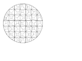
以下、本発明を実施するための好適な形態について適宜図面を参照しながら詳細に説明する。図1は、本発明の成形板が設置されたかき揚げ製造装置の概略図である。図2は、本発明にかかる成形板の説明図であって、(a)が平面図、(b)が(a)のA−A断面矢視図である。なお、以下に説明する実施形態は、本発明の代表的な実施形態の一例を示したものであり、これにより本発明の範囲が狭く解釈されることはない。 DESCRIPTION OF EXEMPLARY EMBODIMENTS Hereinafter, preferred embodiments for carrying out the invention will be described in detail with reference to the drawings as appropriate. FIG. 1 is a schematic view of a kakiage manufacturing apparatus in which the molded plate of the present invention is installed. 2A and 2B are explanatory diagrams of the molded plate according to the present invention, in which FIG. 2A is a plan view and FIG. 2B is a cross-sectional view taken along the line AA in FIG. In addition, embodiment described below shows an example of typical embodiment of this invention, and, thereby, the range of this invention is not interpreted narrowly.
まず、本発明の成形板を備えたかき揚げ製造装置について説明する。
図1に示すかき揚げ製造装置1は、いわゆる衣液と具材が混ぜ合わされたバッターを所定量ずつリテーナーに投入した後、油槽で揚げることによってかき揚げを製造するための装置である。そして、このかき揚げ装置1には、リテーナーに投入されたバッターを成形するための成形装置が設置されている。
First, the deep-fried kaki manufacturing apparatus provided with the shaping | molding board of this invention is demonstrated.
A kakiage manufacturing apparatus 1 shown in FIG. 1 is an apparatus for manufacturing kakiage by putting a batter mixed with so-called clothing liquid and ingredients into a retainer by a predetermined amount and then frying it in an oil tank. The kneading device 1 is provided with a molding device for molding the batter that has been put into the retainer.
図1に示すように、かき揚げ製造装置1は、主に、バッター供給装置10と、バッター成形装置20と、バッターを揚げるための油槽30と、リテーナーを搬送するための搬送装置40とを備えて構成されている。
As shown in FIG. 1, the kakiage manufacturing apparatus 1 mainly includes a
バッター供給装置10は、搬送装置40上に並んだリテーナーにバッターを供給すための装置であり、混合されたバッターを貯留するホッパー11と、ホッパー11内のバッターをリテーナーに供給する充填ノズル部12を有している。
The
ホッパー11は、バッターを貯留しておくためのものである。バッターはホッパー11内で具材と衣液を混ぜて作成してもよいし、予め作成しておいたバッターをホッパー11内に供給しても良い。 The hopper 11 is for storing a batter. The batter may be prepared by mixing ingredients and liquid in the hopper 11 or a batter prepared in advance may be supplied into the hopper 11.
充填ノズル部12は、ホッパー11内のバッターを連続駆動しているリテーナー内に供給するための装置である。充填ノズル部12は、ホッパー11下部に設けられた配管の先端に配置されている。また、充填ノズル部12の開閉はシステム制御されており、リテーナーに対して定量的にバッターを供給することができる。
なお、定量的にバッターを供給する方法としては、重量で供給量を制御する方法もある。
The filling nozzle unit 12 is a device for supplying a batter in the hopper 11 into a retainer that is continuously driven. The filling nozzle portion 12 is disposed at the tip of a pipe provided at the lower part of the hopper 11. Moreover, the opening and closing of the filling nozzle unit 12 is system controlled, and the batter can be quantitatively supplied to the retainer.
In addition, as a method of supplying batter quantitatively, there is also a method of controlling the supply amount by weight.
成形装置20は、バッター供給装置10によってリテーナーに供給されたバッターを一定の厚みに成形する装置であるとともに、手造りしたかのような凹凸形状をバッターの表面に付与する機能も有している。
The
図1に示すように、成形装置20は、バッターを押圧する成形板21と、該成形板21を上下に移動させてリテーナー中のバッターに成形板21を押し当てることができるようにするための駆動手段22と、を備えて構成される。
As shown in FIG. 1, the
成形板21は、平面視円形の板状部材であって、バッター供給装置10から供給されるバッターの厚みを均一に整えるための部材である。成形板21は一列あたり複数個配置されている。
The forming
成形板21は押圧した時に変形しない程度の剛性を備えている素材で構成されている。成形板21の素材としては、例えば、鉄、ステンレス、銅などの金属や、プラスチック、テフロン(登録商標)などの合成樹脂が上げられる。
The
ここで、図2(a)及び(b)に示すように、成形板21の片面には縦横で直行する複数の凹部23(以下、「溝23」と言う。)と、溝23によって囲まれた複数の凸部24が形成されている。
Here, as shown in FIGS. 2 (a) and 2 (b), one side of the
溝23は、バッターを押圧した際に、バッターと成形板21との間の空気を外部に排出する役割を果たす。
The
図2(b)に示すように、各溝23は直行するように等間隔に設けられており、バッターとの接触面に向かって溝幅が漸増している。また、溝23は成形板21の周縁部にまで到達している。そして、複数の溝23を設けることによって、後述する複数の凸部24が形成されている。
なお、溝23の溝幅は、バッターとの接触面に向かって漸増する形状に限られず、等間隔であっても良い。また、溝は成形板の両面に設けられていてもよい。
As shown in FIG. 2B, the
The groove width of the
凸部24は、バッターを押圧した際に、バッターの表面に手造りしたかのような凹凸形状を付与する。
The
本実施例において、凸部24は角錐台形状である。より詳しくは、凸部24は溝23を設けることによって形成されたものであり、規則正しく配置されている。また、角錐台における上面及び底面の中心が一致している。
In the present embodiment, the
ここで、凸部24の高さhは5〜10mmの範囲であることが好ましい。5mm未満だと、押圧した際に溝23のすべてがバッターで埋まってしまい、バッターと成形板21との間の空気を排出することができない。一方、高さhが10mmを超えてしまうと、凸部24の先端がリテーナーまで突き抜けてしまうか、高さを出すために成形板21を大きくせざるをえず、成形しづらくなるという問題がある。
Here, the height h of the
また、凸部24の一辺wは3mm以上であることが好ましい。3mm未満だと凹凸が小さく手造り感を付与できない。
Moreover, it is preferable that the one side w of the
さらに、隣り合う角錐台の面同士がなす角度αが75°〜120°の範囲であることが好ましい。75°未満だと凸部24同士の距離が近くなり、手造り感を付与できないばかりか、具材が面と面の間に挟まりこみやすいという問題がある。また、120°より大きいと成形板21上の凸部24の数が足りないか、凸部24の高さが十分確保できず、バッターが付着する恐れがある。
Furthermore, it is preferable that the angle α formed by the surfaces of the adjacent truncated pyramids is in the range of 75 ° to 120 °. If the angle is less than 75 °, the distance between the
なお、凸部24の形状は、角錐台形状に限られず、円錐、円錐台、円柱、多角錐、多角錐台、多角柱などであってもよく、これらの組み合わせでも良い。また、各凸部24において、上面と底面の中心がずれていても良い。
The shape of the
駆動手段22は、後述する搬送手段40にあわせて、成形板21を上下に復動させるために設けられる。本実施例においては、駆動手段22と成形板21は、成形板21の凹凸部が設けられている面とは反対側の面でシリンダ等を介して接合している。
The drive means 22 is provided to move the
駆動手段22については、成形板21を上下に複動させることができれば、構成は特に制限されない。駆動手段22の具体例としては、無端回動コンベアやモータなどが挙げられる。
The configuration of the driving unit 22 is not particularly limited as long as the
無端回動コンベアを用いる場合、コンベアの軌道の一部に後述する搬送手段40へ向けて突出した区間を設ければよい。これにより、コンベアの軌道に従って成形板21が移動すると、突出した区間を通過するときに成形板21が下降する。そして、成形板21が下降することで、バッターを押圧し成形することができる。
In the case of using an endless rotating conveyor, a section protruding toward the conveying means 40 described later may be provided in a part of the track of the conveyor. Thereby, if the shaping | molding
一方、モータを用いる場合、カムを用いればよい。カムを用いることで、成形板21を上下に駆動させることができる。
On the other hand, when using a motor, a cam may be used. By using the cam, the
なお、コンベア、モータ、カム等は既存の技術を用いることができ、特に制限されない。 The conveyor, the motor, the cam, and the like can use existing techniques and are not particularly limited.
油槽30は、成形されたバッターを油揚げするための装置である。油槽30は、移送手段40の進行方向上であって、バッター供給装置10、成形装置20の後に設けられている。
The
油槽30中には、植物性油脂、動物性油脂またはこれらの組み合わせで満たされている。また油槽30中の油脂は、ヒーターなどによって適温に保たれている。
The
油槽30の幅と長さは特に制限されないが、複数列のリテーナーが一度に入る幅を有し、揚げ時間が十分に確保できる長さであることが好ましい。
The width and length of the
移送手段40は、リテーナーを連続的に移動させ、供給されたバッターを各工程に搬送するための装置である。移送手段40は、例えば、コンベアとリテーナーとで構成されている。コンベア上には、コンベアの幅方向に成形装置20の成形板数に対応する複数個のリテーナーが設けられ、かつ、コンベアの周方向に対して等間隔に複数設けられている。
The transfer means 40 is an apparatus for continuously moving the retainer and transporting the supplied batter to each step. The transfer means 40 is composed of, for example, a conveyor and a retainer. On the conveyor, a plurality of retainers corresponding to the number of forming plates of the forming
コンベアはリテーナーを搬送するための装置である。コンベアは無端回動であり、連続駆動しながら各工程を周回するようになっている。 The conveyor is a device for conveying the retainer. The conveyor is endlessly rotated and circulates each process while being continuously driven.
図1に示すように、移送手段の一区間が油槽30中に進入することで、リテーナーは油槽30中に浸漬するようになっている。移送手段40としては、単一のコンベアでも良いし、複数のコンベアを組み合わせてもよい。たとえば、油槽30中に別のコンベアを設け、リテーナーの受渡を行うようにしても良い。
As shown in FIG. 1, the retainer is immersed in the
リテーナーはバッターの受け皿であるとともに、かき揚げなどの型として機能する。リテーナーはコンベア上に設けられており、コンベアの駆動に従い、各工程を周回する。 The retainer is a batter tray and functions as a type of kakiage. The retainer is provided on the conveyor, and circulates each process according to the driving of the conveyor.
リテーナーの素材・形状等は特に制限されないが、耐熱性、耐久性などの観点から鉄製、スチール製、ステンレス製などが好ましい。 The material and shape of the retainer are not particularly limited, but iron, steel, stainless steel, etc. are preferable from the viewpoint of heat resistance and durability.
次に、かき揚げ製造装置1の動作およびかき揚げの製造方法について説明する。 Next, the operation of the kakiage manufacturing apparatus 1 and the method for manufacturing the kakiage will be described.
まず、ホッパー11内のバッターが、充填ノズル部12から移送手段40のリテーナーに供給される。このとき、複数のリテーナーに対して一つの充填ノズル部12でバッターを供給しても良いが、一列当たりのリテーナーの数に対応した数だけ充填ノズル部12が設けられていることが好ましい。これにより、一度に大量生産が可能となる。また、充填ノズル部12の開閉時間はシステムによって制御されている。これにより、各リテーナーに対して略同じ量のバッターを供給することができる。さらに、充填ノズル部12の開閉は、リテーナーの動きに合わせて行われる。なお、供給されるバッターは空気が混入していないことが好ましい。空気が混入していると、バッターの供給量にばらつきが生じるためである。 First, the batter in the hopper 11 is supplied from the filling nozzle portion 12 to the retainer of the transfer means 40. At this time, the batter may be supplied to a plurality of retainers by one filling nozzle part 12, but it is preferable that the number of filling nozzle parts 12 corresponding to the number of retainers per row is provided. This allows mass production at once. The opening / closing time of the filling nozzle unit 12 is controlled by the system. Thereby, substantially the same amount of batter can be supplied to each retainer. Further, the opening and closing of the filling nozzle portion 12 is performed in accordance with the movement of the retainer. In addition, it is preferable that air is not mixed in the batter supplied. This is because, if air is mixed, the batter supply amount varies.
リテーナーに供給されたバッターは、次に成形工程に移送される。成形工程では、移送手段40の上部に設けられた成形装置20から成形板21が下降し、リテーナー中のバッターを押圧する。ここで、成形装置20の駆動手段22であるコンベアと成形板21とはシリンダによって連結されており、コンベアの周回とともに成形板21も周回するようになっている。そして、成形装置20のコンベアの一部は下方に突き出た(すなわち移送手段40側に突き出た)区間を有しており、この区間を移動する際に成形板21が最も下降した状態を維持するようになっている。さらに、成形装置20のコンベアも移送手段のコンベアと同調するように連続駆動しているため、成形板21が再度上昇しない限りバッターを押圧し続けることとなる。これにより、継続的な押圧が可能となり、バッターを均一な厚みに均すことができる。
The batter supplied to the retainer is then transferred to the molding process. In the molding step, the
成形板21は、リテーナーの動きと同調するように下降し、リテーナーの中央に供給されたバッターと接触する。そして、そのまま下降を続け、バッターを押圧する。バッターは成形板21に押圧されることでリテーナー中に広がり均一な厚みに成形される。また、成形板21によって、バッターの表面には凹凸が設けられる。このとき、成形板21には周縁部まで到達する溝が設けられているため、押圧しても成形板21とバッターの間の空気が溝23を通じて外に排出される。これにより、成形板21とバッターとの間に真空ができず、成形板21へのバッターの付着を防止することができる。また、成形板21への付着を防ぐことができるので、重量のばらつきや厚みのばらつきを抑えることができる。さらに、バッターの表面に設けられた凹凸によって手造り感を奏することができる。つまり、従来のように別装置を設けることなく、成形と手造り感の付与を一度に行うことができる。
The forming
次に、成形装置20で成形されたバッターは油揚げ工程に移送される。ここで、移送手段40の一区間は油槽30中に進入するように配置されている。これにより、リテーナーが油槽30中に導かれ、バッターは油揚げされる。かき揚げは、リテーナーを反転するなどしてリテーナーから取り出され、別の移送手段によって油槽から引き揚げられる。一方、空になったリテーナーは周回して、再度かき揚げ製造工程に使用される。
Next, the batter formed by the forming
以上、本発明の実施形態について説明したが、本発明は前記実施例に限定されない。例えば、図3に示すように、成形板の各凸部において、上面と底面の中心がずれた形状としても良い。これにより、より手造り感を増すことが出来る。 As mentioned above, although embodiment of this invention was described, this invention is not limited to the said Example. For example, as shown in FIG. 3, it is good also as a shape where the center of the upper surface and the bottom face shifted | deviated in each convex part of a shaping | molding board. Thereby, a handmade feeling can be increased.
また、前記実施例では各凹部が等間隔に設けられ、かつ、各凹部同士が直行する例を示したが、これに限られず、間隔が不揃い、及び/又は、直行していない形状としても良い。この場合においても、本発明の目的を達成することができる。 In the above embodiment, the concave portions are provided at equal intervals and the concave portions are orthogonal to each other. However, the present invention is not limited to this, and the intervals may be irregular and / or not orthogonal. . Even in this case, the object of the present invention can be achieved.
さらに、前記実施例では、かき揚げ製造装置に成形板を用いた場合を例に説明したが、これに限られず、手作業で行う場合に用いても良い。この場合においても、かき揚げの成形を簡便に行うことができる。 Furthermore, in the said Example, although the case where the shaping | molding board was used for the kakiage manufacturing apparatus was demonstrated to the example, it is not restricted to this, You may use when performing manually. Also in this case, the kakiage can be formed easily.
21 成形板
23 凹部(溝)
24 凸部
α 角度
h 高さ
w 幅
21 Molded
24 Convex α Angle h Height w Width
Claims (4)
成形板の少なくとも片面に複数の溝を設けることで複数の凸部を形成され、
前記複数の溝は成形板の周縁部まで到達している成形板。 A molding plate for molding a batter supplied to a retainer,
A plurality of convex portions are formed by providing a plurality of grooves on at least one surface of the molded plate ,
The molding plate in which the plurality of grooves reach the peripheral edge of the molding plate.
Priority Applications (4)
| Application Number | Priority Date | Filing Date | Title |
|---|---|---|---|
| JP2014027527A JP6208037B2 (en) | 2014-02-17 | 2014-02-17 | Molded plate |
| TW104103869A TWI590768B (en) | 2014-02-17 | 2015-02-05 | Forming plate |
| CN201510085150.1A CN104839272B (en) | 2014-02-17 | 2015-02-16 | Forming board |
| HK15111715.4A HK1214087A1 (en) | 2014-02-17 | 2015-11-27 | Mould plate |
Applications Claiming Priority (1)
| Application Number | Priority Date | Filing Date | Title |
|---|---|---|---|
| JP2014027527A JP6208037B2 (en) | 2014-02-17 | 2014-02-17 | Molded plate |
Publications (2)
| Publication Number | Publication Date |
|---|---|
| JP2015150272A JP2015150272A (en) | 2015-08-24 |
| JP6208037B2 true JP6208037B2 (en) | 2017-10-04 |
Family
ID=53839574
Family Applications (1)
| Application Number | Title | Priority Date | Filing Date |
|---|---|---|---|
| JP2014027527A Active JP6208037B2 (en) | 2014-02-17 | 2014-02-17 | Molded plate |
Country Status (4)
| Country | Link |
|---|---|
| JP (1) | JP6208037B2 (en) |
| CN (1) | CN104839272B (en) |
| HK (1) | HK1214087A1 (en) |
| TW (1) | TWI590768B (en) |
Families Citing this family (3)
| Publication number | Priority date | Publication date | Assignee | Title |
|---|---|---|---|---|
| JP6737651B2 (en) * | 2016-07-12 | 2020-08-12 | 日清食品ホールディングス株式会社 | Molding method for fried mixture |
| CN105995534A (en) * | 2016-07-23 | 2016-10-12 | 安徽宏锦包装设备有限公司 | Rice crust hemisphere forming head |
| CN105996101A (en) * | 2016-07-23 | 2016-10-12 | 安徽宏锦包装设备有限公司 | Non-sticky forming head of hemispherical rice crust former |
Family Cites Families (8)
| Publication number | Priority date | Publication date | Assignee | Title |
|---|---|---|---|---|
| JPH11253326A (en) * | 1998-03-09 | 1999-09-21 | Osaka Gas Co Ltd | Deep frying cooker |
| JP3051961B1 (en) * | 1999-02-04 | 2000-06-12 | 株式会社金竜食品産業 | Kakiage tempura manufacturing equipment |
| JP4351454B2 (en) * | 2003-03-06 | 2009-10-28 | 日本水産株式会社 | Deep-fried kakiage, deep-fried mold for kakiage, and kakiage manufacturing method |
| JP2005186020A (en) * | 2003-12-26 | 2005-07-14 | Samy:Kk | Filter medium, food fryer equipped therewith and filter medium manufacturing method |
| JP4545767B2 (en) * | 2007-02-28 | 2010-09-15 | 大王製紙株式会社 | Kitchen paper |
| JP2008154659A (en) * | 2006-12-21 | 2008-07-10 | Matsushita Electric Ind Co Ltd | Cooker |
| FR2924574B1 (en) * | 2007-12-10 | 2013-04-26 | Seb Sa | MOLD FOR REALIZING FOOD BASED ON PULP SWAPING UNDER HEAT |
| JP5798820B2 (en) * | 2011-07-12 | 2015-10-21 | 昭和産業株式会社 | Support plate and auxiliary equipment for frying |
-
2014
- 2014-02-17 JP JP2014027527A patent/JP6208037B2/en active Active
-
2015
- 2015-02-05 TW TW104103869A patent/TWI590768B/en active
- 2015-02-16 CN CN201510085150.1A patent/CN104839272B/en active Active
- 2015-11-27 HK HK15111715.4A patent/HK1214087A1/en unknown
Also Published As
| Publication number | Publication date |
|---|---|
| TW201540199A (en) | 2015-11-01 |
| HK1214087A1 (en) | 2016-07-22 |
| JP2015150272A (en) | 2015-08-24 |
| CN104839272B (en) | 2019-06-14 |
| CN104839272A (en) | 2015-08-19 |
| TWI590768B (en) | 2017-07-11 |
Similar Documents
| Publication | Publication Date | Title |
|---|---|---|
| KR101968062B1 (en) | Apparatus for forming a sheet-like dough from a dough piece by pressing | |
| JP6208037B2 (en) | Molded plate | |
| US20120177786A1 (en) | Moulding device, moulding member, moulding method, food preparation method and moulded product | |
| KR20110111990A (en) | Manufacturing apparatus of donuts | |
| CN107668110B (en) | Uniform distribution device | |
| JP5467426B2 (en) | Dora-yaki manufacturing equipment | |
| KR101418936B1 (en) | Fried egg manufacture device | |
| JP2010246463A (en) | Food baking method and apparatus for the same | |
| JP6737651B2 (en) | Molding method for fried mixture | |
| CN107646925B (en) | Cake arranging machine | |
| JP7321091B2 (en) | Food coating equipment and food production method | |
| JP2017514502A (en) | Stamp plate with molding stop | |
| KR101265207B1 (en) | Snack frying apparatus and snack frying system using it | |
| JP2010264025A (en) | Fryer basket | |
| KR101444796B1 (en) | product equipment for rice cake | |
| KR20200000872U (en) | Baking pan | |
| KR101576725B1 (en) | Soft bread auto-making equipment | |
| JP3447343B2 (en) | Food baking method and apparatus | |
| JP5903227B2 (en) | Spherical food production method and apparatus | |
| JP4182382B2 (en) | Method and apparatus for manufacturing baked confectionery | |
| CN107668111B (en) | Baking device | |
| KR102058324B1 (en) | Apparatus for manufacturing of a boiled fish paste | |
| JP4294395B2 (en) | Omelette filling equipment | |
| CN107581203B (en) | Cake forming machine | |
| KR20210131571A (en) | Nurungji Discharge device of Nurungji Manufacturing System |
Legal Events
| Date | Code | Title | Description |
|---|---|---|---|
| A621 | Written request for application examination |
Free format text: JAPANESE INTERMEDIATE CODE: A621 Effective date: 20160704 |
|
| A977 | Report on retrieval |
Free format text: JAPANESE INTERMEDIATE CODE: A971007 Effective date: 20170424 |
|
| A131 | Notification of reasons for refusal |
Free format text: JAPANESE INTERMEDIATE CODE: A131 Effective date: 20170509 |
|
| A521 | Request for written amendment filed |
Free format text: JAPANESE INTERMEDIATE CODE: A523 Effective date: 20170620 |
|
| TRDD | Decision of grant or rejection written | ||
| A01 | Written decision to grant a patent or to grant a registration (utility model) |
Free format text: JAPANESE INTERMEDIATE CODE: A01 Effective date: 20170905 |
|
| A61 | First payment of annual fees (during grant procedure) |
Free format text: JAPANESE INTERMEDIATE CODE: A61 Effective date: 20170906 |
|
| R150 | Certificate of patent or registration of utility model |
Ref document number: 6208037 Country of ref document: JP Free format text: JAPANESE INTERMEDIATE CODE: R150 |
|
| R250 | Receipt of annual fees |
Free format text: JAPANESE INTERMEDIATE CODE: R250 |
|
| R250 | Receipt of annual fees |
Free format text: JAPANESE INTERMEDIATE CODE: R250 |
|
| R250 | Receipt of annual fees |
Free format text: JAPANESE INTERMEDIATE CODE: R250 |
|
| R250 | Receipt of annual fees |
Free format text: JAPANESE INTERMEDIATE CODE: R250 |