JP6200625B2 - Undercarriage of truck bed and truck - Google Patents
Undercarriage of truck bed and truck Download PDFInfo
- Publication number
- JP6200625B2 JP6200625B2 JP2014075805A JP2014075805A JP6200625B2 JP 6200625 B2 JP6200625 B2 JP 6200625B2 JP 2014075805 A JP2014075805 A JP 2014075805A JP 2014075805 A JP2014075805 A JP 2014075805A JP 6200625 B2 JP6200625 B2 JP 6200625B2
- Authority
- JP
- Japan
- Prior art keywords
- floor
- inner space
- side skirt
- truck bed
- hook
- Prior art date
- Legal status (The legal status is an assumption and is not a legal conclusion. Google has not performed a legal analysis and makes no representation as to the accuracy of the status listed.)
- Active
Links
Images


Description
本発明はトラック荷台の下部構造及びこの構造を備えるトラックに関し、特に横根太とサイドスカートとの接合部の構造を改良することで床フックの取り付け位置・間隔・個数を自在に調節できるトラック荷台の下部構造及びトラックに関する。 The present invention relates to a lower structure of a truck bed and a truck having this structure, and more particularly to a truck bed that can freely adjust the mounting position, interval, and number of floor hooks by improving the structure of the joint between the side joist and the side skirt. It relates to the substructure and the track.
一般的なトラックの荷台は、図3(a)〜(c)に示すように横根太100を車両の前後方向に所定の間隔で配置し、横根太100の上部に床板101を敷設すると共に横根太100の左右の端部を、断面コ字状で前後方向にのびるサイドスカート102の内側空間102aで覆う構造になっている。なお、理解を容易にするために図3(c)の平面図においては床板101やサイドスカート102の一部等の図示を省略している。
サイドスカート102の上面には長手方向に適当な間隔で貫通穴を設けており、この貫通穴に荷役用の床フック103の基部103aを通すことでサイドスカートの内側空間102a内に床フック103を出し入れ自在に格納する構造になっている。また、サイドスカートの内側空間102aのうち床フック103が出入りする箇所を床フック用カバー104で覆うことで、床フックの基部103aの汚れ防止及び荷台下部から埃、水分、光等が貫通穴を通過して荷室内に侵入することがないようにしている。
As shown in FIGS. 3 (a) to 3 (c), a general truck bed is provided with
Through holes are provided in the upper surface of the
ここで、床フック103はユーザーの要望に応じてその取り付け位置・間隔・個数を自在に調節可能であることが好ましいが、上述した従来の構造の場合、横根太100が配置されている箇所ではサイドスカートの内側空間102aの大部分を横根太100の端部が占めており、当該端部が邪魔になるため、この箇所の近傍には床フック103及び床フック用カバー104を取り付けることができないという問題がある。つまり、トラック荷台の下部構造の設計段階において横根太100の配置の方が優先されるため、横根太100の配置が決まった後、床フック103の取り付け位置等を横根太100と干渉しない範囲内で決定せざるを得ないという問題がある。
このような問題を考慮して、例えば特許文献1には、床板(フロアパネル)をFRP製にすると共に床板の端部に直接サイドスカート(サイドレール)を取り付ける構造にすることで、床フックを床板表面の所望の位置に取り付けられる技術が開示されている。
Here, it is preferable that the mounting position, interval, and number of the
Considering such a problem, for example, in Patent Document 1, a floor board (floor panel) is made of FRP and a side skirt (side rail) is directly attached to an end portion of the floor board so that a floor hook is attached. A technique for attaching to a desired position on the floorboard surface is disclosed.
しかし、上記従来技術の場合には以下のような問題がある。
すなわち、床板表面の所望の位置に形成したボルト穴を利用して床フックを固着することになるため、床フックを出し入れ自在な構造にできず、床フックを使用しない際や荷物の搬出入の際に床フックが邪魔になるという問題がある。
また、従来技術はFRP製の床板に適用し得る技術であり、トラック荷台の下部構造として一般的な横根太の端部にサイドレールを取り付けた構造には適用できないという問題がある。
However, in the case of the above-described conventional technology, there are the following problems.
In other words, the floor hook is fixed using a bolt hole formed at a desired position on the floor board surface, so the floor hook cannot be made into a structure that can be freely inserted and removed. There is a problem that the floor hook gets in the way.
Further, the conventional technology is a technology that can be applied to a floor plate made of FRP, and there is a problem that it cannot be applied to a structure in which a side rail is attached to an end portion of a common horizontal joist as a lower structure of a truck bed.
本発明はこのような問題に鑑み、横根太の端部にサイドレールを取り付ける構造において、床フックを出し入れ自在且つ床フックの取り付け位置・間隔・個数を自在に調節できるトラック荷台の下部構造及びこの構造を備えるトラックを提供することを目的とする。 In view of such a problem, the present invention has a structure for attaching a side rail to the end of a horizontal joist, and a lower structure of a truck bed that allows the floor hooks to be taken in and out and the position, interval, and number of floor hooks to be freely adjusted. The object is to provide a truck with a structure.
本発明のトラック荷台の下部構造は、車両の前後方向に間隔をあけて配置される複数の横根太と、横根太の端部に取り付けられて車両の前後方向にのびる断面略コ字状のサイドスカートと、サイドスカートの略コ字状によって画定される内側空間内に出し入れ自在に格納される床フックと、当該内側空間内に配置されて前記床フックの基部を覆う床フック用カバーとからなるトラック荷台の下部構造であって、前記床フック用カバーを配置し得る寸法の空隙部を前記内側空間内の長手方向全域に亘って設けることを特徴とする。
また、前記サイドスカートが、横根太上の床板を位置決め・固定するための凸部と、当該凸部から車両の中央方向にのびる薄板状の延伸部とを備えており、床板及び延伸部を横根太に対してボルト締めで一体的に固定することを特徴とする。
本発明のトラックは、上記トラック荷台の下部構造を備えることを特徴とする。
The lower structure of the truck bed of the present invention includes a plurality of horizontal joists arranged at intervals in the front-rear direction of the vehicle, and a side having a substantially U-shaped cross section that is attached to the end of the horizontal joists and extends in the front-rear direction of the vehicle A skirt, a floor hook which is stored in an inner space defined by a substantially U-shape of the side skirt, and a floor hook cover which is disposed in the inner space and covers the base of the floor hook. It is a lower structure of a truck bed, and is characterized in that a gap having a dimension capable of arranging the floor hook cover is provided over the entire longitudinal direction in the inner space.
The side skirt includes a convex portion for positioning and fixing the floor board on the horizontal joist and a thin plate-like extending portion extending from the convex portion toward the center of the vehicle. It is characterized in that it is fixed integrally with a bolt by bolting.
A truck according to the present invention includes the lower structure of the truck bed.
本発明では、床フック用カバーを内側空間の空隙部内に配置する。空隙部は内側空間内の長手方向全域に亘って設けられているので、床フック用カバーを内側空間内の任意の場所に取り付けることができる。したがって、床フック及び床フック用カバーの取り付け位置を決める際に、従来のように横根太との干渉を考慮することなく、ユーザーの要望に応じた位置・間隔・個数の調節が可能になる。
また、サイドスカートに凸部と延伸部を設けて、床板と延伸部とを横根太に対して一体的に締結・固定することで、床板表面の水分が横根太にまで侵入しない程度の防水性を確保できる。
In the present invention, the floor hook cover is disposed in the gap in the inner space. Since the gap is provided over the entire longitudinal direction in the inner space, the floor hook cover can be attached to any location in the inner space. Therefore, when determining the mounting position of the floor hook and the floor hook cover, it is possible to adjust the position, the interval, and the number according to the user's request without considering the interference with the lateral joist as in the prior art.
In addition, the side skirt is provided with a convex part and an extension part, and the floor board and the extension part are integrally fastened and fixed to the side joist so that the moisture on the floor board surface does not penetrate into the side joist. Can be secured.
[第1の実施の形態]
本発明のトラック荷台の下部構造の第1の実施の形態について説明する。なお、以下の説明において車両の進行方向を「前方」と表記する。また、トラック荷台の下部構造はおおよそ左右対称になっているため、以下、主に左側の下部構造について説明する。
図1(a)〜(c)に示すように、本実施の形態におけるトラック荷台の下部構造10は、トラックのシャーシフレーム11に荷台を取り付けるための構造であり、横根太20、サイドスカート30、床フック40及び床フック用カバー50、縦根太60及びスペーサー70から概略構成される。前後方向にのびるシャーシフレーム11の上面にはスペーサー70を挟んで縦根太60が配置され、縦根太60と横根太20とが連結板(図示略)で連結される。なお、理解を容易にするために図1(c)の平面図においては床材やサイドスカート30の一部等の図示を省略している。
[First Embodiment]
A first embodiment of the lower structure of a truck bed according to the present invention will be described. In the following description, the traveling direction of the vehicle is expressed as “front”. In addition, since the lower structure of the truck bed is roughly symmetrical, the following description will mainly focus on the left lower structure.
As shown in FIGS. 1A to 1C, the
横根太20は車両の前後方向に間隔をあけて複数配置される。横根太20の形状は特に限定されるものではなく、断面が略L字状、I字状、T字状、H字状、コ字状等であってよい。また、横根太20の材質も特に限定されるものではなくスチール、アルミニウム、アルミニウム合金等の一般的な材料を使用できる。
A plurality of
サイドスカート30は横根太20の端部に取り付けられて前後方向にのびる断面略コ字状の部材である。また、サイドスカート30の略コ字状によって内側空間31が画定され、この内部空間31の開口部31aが車両の内側を向くようにして横根太20に取り付けられる。詳しい説明は後述するが、サイドスカート30の上面には長手方向に沿って適当な間隔で貫通穴32が形成されており、また、内側空間31の長手方向全域に亘って空隙部33が設けられている。貫通穴32はサイドスカート30の製造時に形成してもよく、あるいはユーザーが床フック40の所望の取り付け位置を決定した段階で形成してもよい。サイドスカート30の材質も特に限定されるものではなくスチール、アルミニウム、アルミニウム合金、ステンレス等の一般的な材料を使用できる。
本発明においてサイドスカート30の断面形状が「略コ字状」であるとは、サイドスカート30を横根太20の端部に取り付けた状態において、横根太20の端面を覆うべく鉛直方向にのびる鉛直部材34aと、当該鉛直部材34aの下端から車両の内側に向かってのびる下側部材34bと、鉛直部材34aの上端から車両の内側に向かってのびる上側部材34cの3つの部材から成る形状を指すものとする。これら3つの部材の相対的な大小関係に制限はなく、例えば上側部材34cが下側部材34bに対して極端に大きい(あるいは小さい)形状であってもよい。また、これら3つの部材によって囲まれる空間を本発明における「内側空間31」とする。
サイドスカート30の上面(上記上側部材34c)には、床板12を位置決め・固定するための凸部35をその長手方向(車両の前後方向)に沿って設けている。また、凸部35から車両の中央方向に向かって薄板状の延伸部36を設けている。そして、皿ボルト37aを用いて床板12と延伸部36とを横根太20に対して一体的に締結・固定することで、床板12表面の水分が横根太20にまで侵入しない程度の防水性を確保している。サイドスカート30の下面(上記下側部材34b)も横根太20に対してボルト37bで締結・固定している。
The
In the present invention, the cross-sectional shape of the
On the upper surface of the side skirt 30 (the
床フック40はサイドスカート30の内側空間31内に出し入れ自在に格納される部材であり、サイドスカート30の長手方向に沿って複数取り付けられる。
床フック40は、水平面内で前後方向にのびるフック本体41と、フック本体41の前後の端部近傍から下方にのびる2本の基部42によって略Π字状に形成されている。フック本体41は常にサイドスカート30の上面から外部(荷室内)に露出しており、2本の基部42はサイドスカート30上面の貫通穴32に通されている。使用時にフック本体41を持ち上げると基部42が内側空間31から外部に引き出され、基部42の下端に取り付けてあるストッパー43が上側部材34cの下面に接触することで床フック40が貫通穴32から抜け出ないようになっている。また、未使用時には自重により基部42が内側空間31内に下がっていくことでフック本体41のみが外部に露出する仕組みになっている。床フック40の形状は特に限定されるものではなく、例えば2本の基部42の上端からフック本体41にかけて滑らかに繋がる略U字状や、基部42が1本の略T字状等であってもよい。
The
The
床フック用カバー50は内側空間31内において床フック40の基部42を覆う部材である。床フック用カバー50は平面視略コ字状の部材であり、各端面をサイドスカート30の鉛直部材34a、上側部材34c及び下側部材34bに固着することで、床フック40の基部42の汚れ防止及び荷台下部から埃、水分、光等が貫通穴32を通過して荷室内に侵入することを防止している。
床フック用カバー50は内側空間31に設けられる空隙部33内に配置される。換言すると、空隙部33内に床フック用カバー50を配置できるように空隙部33と床フック用カバー50の寸法を決定する。上述の通り空隙部33は内側空間31内の長手方向全域に亘って設けられているので、内側空間31内における床フック用カバー50の取り付け位置を決める際に、従来のように横根太20との干渉を考慮することなく、所望の位置を選択することができる。つまり、ユーザーの要望に応じた床フック40の取り付け位置・間隔・個数の調節が可能になる。
The floor hook cover 50 is a member that covers the
The floor hook cover 50 is disposed in a
[第2の実施の形態]
次に、本発明のトラック荷台の下部構造の第2の実施の形態について説明するが、上記第1の実施の形態と同一の構造になる箇所については同一の符号を付してその説明を省略する。
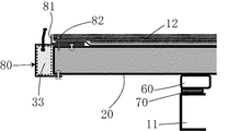
図2に示すように、本実施の形態ではサイドスカート80が横根太20上の床板12を位置決め・固定するための凸部35を備えず、その替わりに断面L字状の位置決め部材81を備える点に特徴を有する。
位置決め部材81は床板12とサイドスカート30に上下から挟まれる位置に配置され、ボルト82を用いて床板12と位置決め部材81とサイドスカート30を横根太20に対して一体的に締結・固定している。
位置決め部材81を用いることでサイドスカート30の形状を簡略化できるため、サイドスカート30の製造コストを抑制することができる。
[Second Embodiment]
Next, the second embodiment of the lower structure of the truck bed according to the present invention will be described. However, the same reference numerals are given to the portions having the same structure as the first embodiment, and the description thereof is omitted. To do.
As shown in FIG. 2, in the present embodiment, the
The positioning
Since the shape of the
本発明は、床フックを出し入れ自在且つ床フックの取り付け位置・間隔・個数を自在に調節できるトラック荷台の下部構造に関するものであり、産業上の利用可能性を有する。 The present invention relates to a lower structure of a truck bed in which floor hooks can be taken in and out and the mounting position, interval, and number of floor hooks can be freely adjusted, and have industrial applicability.
10 トラック荷台の下部構造
11 シャーシフレーム
12 床板
20 横根太
30 サイドスカート
31 内側空間
31a 開口部
32 貫通穴
33 空隙部
34a 鉛直部材
34b 下側部材
34c 上側部材
35 凸部
36 延伸部
37a 皿ボルト
37b ボルト
40 床フック
41 フック本体
42 基部
43 ストッパー
50 床フック用カバー
60 縦根太
70 スペーサー
80 サイドスカート
81 位置決め部材
82 ボルト
10 Substructure of truck bed
11 Chassis frame
12 Floor board
20 Yokoneta
30 side skirts
31 Inside space
31a opening
32 Through hole
33 Gap
34a Vertical member
34b Lower part
34c Upper part
35 Convex
36 Drawing part
37a flat head bolt
37b bolt
40 floor hook
41 Hook body
42 Base
43 Stopper
50 Floor hook cover
60 Vertical joists
70 Spacer
80 side skirt
81 Positioning member
82 volts
Claims (3)
前記床フック用カバーを配置し得る寸法の空隙部を前記内側空間内の長手方向全域に亘って設けることを特徴とするトラック荷台の下部構造。 A plurality of horizontal joists arranged at intervals in the front-rear direction of the vehicle, a side skirt having a substantially U-shaped cross-section attached to an end of the horizontal joist and extending in the front-rear direction of the vehicle, and a substantially U-shaped side skirt A bottom structure of a truck bed comprising a floor hook which is freely stored in and removed from an inner space defined by an inner space, and a floor hook cover which is disposed in the inner space and covers a base portion of the floor hook,
A lower structure of a truck bed, wherein a space having a dimension capable of arranging the floor hook cover is provided over the entire longitudinal direction in the inner space.
A truck comprising the lower structure of the truck bed according to claim 1 or 2.
Priority Applications (1)
| Application Number | Priority Date | Filing Date | Title |
|---|---|---|---|
| JP2014075805A JP6200625B2 (en) | 2014-04-01 | 2014-04-01 | Undercarriage of truck bed and truck |
Applications Claiming Priority (1)
| Application Number | Priority Date | Filing Date | Title |
|---|---|---|---|
| JP2014075805A JP6200625B2 (en) | 2014-04-01 | 2014-04-01 | Undercarriage of truck bed and truck |
Publications (2)
| Publication Number | Publication Date |
|---|---|
| JP2015196468A JP2015196468A (en) | 2015-11-09 |
| JP6200625B2 true JP6200625B2 (en) | 2017-09-20 |
Family
ID=54546442
Family Applications (1)
| Application Number | Title | Priority Date | Filing Date |
|---|---|---|---|
| JP2014075805A Active JP6200625B2 (en) | 2014-04-01 | 2014-04-01 | Undercarriage of truck bed and truck |
Country Status (1)
| Country | Link |
|---|---|
| JP (1) | JP6200625B2 (en) |
Families Citing this family (1)
| Publication number | Priority date | Publication date | Assignee | Title |
|---|---|---|---|---|
| US10857961B2 (en) | 2018-05-23 | 2020-12-08 | Hydro Extrusion USA, LLC | Mounting system for truck underride protection |
Family Cites Families (4)
| Publication number | Priority date | Publication date | Assignee | Title |
|---|---|---|---|---|
| JPH10258777A (en) * | 1997-03-18 | 1998-09-29 | Toray Ind Inc | Bed of truck |
| JPH115569A (en) * | 1997-06-17 | 1999-01-12 | Isuzu Motors Ltd | Side rail structure for resin-made loading deck of truck |
| JP2003335269A (en) * | 2002-05-17 | 2003-11-25 | Nippon Trex Co Ltd | Mounting structure for gate helper |
| JP2009107402A (en) * | 2007-10-26 | 2009-05-21 | Mitsubishi Fuso Truck & Bus Corp | Floor frame member of box-shaped cargo bed |
-
2014
- 2014-04-01 JP JP2014075805A patent/JP6200625B2/en active Active
Also Published As
| Publication number | Publication date |
|---|---|
| JP2015196468A (en) | 2015-11-09 |
Similar Documents
| Publication | Publication Date | Title |
|---|---|---|
| RU2010140581A (en) | VEHICLE BUMPER STRENGTH DESIGN | |
| JP6260018B2 (en) | Harness protector | |
| JP2006298076A (en) | Vehicle body floor structure | |
| JP6200625B2 (en) | Undercarriage of truck bed and truck | |
| CN109109892B (en) | Railway vehicle's chassis subassembly and railway vehicle | |
| JP6094380B2 (en) | Mounting structure for vehicle seat | |
| JP2009107403A (en) | Floor member structure of cargo bed of truck | |
| JP6200626B2 (en) | Truck floor structure with guide rails on the carrier and truck | |
| JP4661399B2 (en) | Carpet luggage floor mounting support structure | |
| JP5847641B2 (en) | Inrush prevention device | |
| JP6126385B2 (en) | Parking equipment pallet | |
| JP5830052B2 (en) | Car body rear structure | |
| JP2017210122A (en) | Floor hook fitting structure and vehicle | |
| US9796438B1 (en) | Vehicle cargo support structure | |
| JP6641630B2 (en) | High roof car bed support structure | |
| JP2019031129A (en) | Railway vehicle body structure | |
| JP2015205566A (en) | Cushion structure of hood for vehicle | |
| JP6769251B2 (en) | Cab floor structure | |
| JP6935317B2 (en) | building | |
| JP2018140666A (en) | Vehicle roof structure | |
| JP2009019410A (en) | Sound arrester | |
| JPS626930Y2 (en) | ||
| JP2020138629A (en) | Floor structure of bus | |
| WO2017154843A1 (en) | Cab rear surface section structure | |
| JP6838309B2 (en) | Vehicle floor panel structure |
Legal Events
| Date | Code | Title | Description |
|---|---|---|---|
| A621 | Written request for application examination |
Free format text: JAPANESE INTERMEDIATE CODE: A621 Effective date: 20161116 |
|
| A977 | Report on retrieval |
Free format text: JAPANESE INTERMEDIATE CODE: A971007 Effective date: 20170728 |
|
| TRDD | Decision of grant or rejection written | ||
| A01 | Written decision to grant a patent or to grant a registration (utility model) |
Free format text: JAPANESE INTERMEDIATE CODE: A01 Effective date: 20170810 |
|
| A61 | First payment of annual fees (during grant procedure) |
Free format text: JAPANESE INTERMEDIATE CODE: A61 Effective date: 20170826 |
|
| R150 | Certificate of patent or registration of utility model |
Ref document number: 6200625 Country of ref document: JP Free format text: JAPANESE INTERMEDIATE CODE: R150 |
|
| R250 | Receipt of annual fees |
Free format text: JAPANESE INTERMEDIATE CODE: R250 |
|
| R250 | Receipt of annual fees |
Free format text: JAPANESE INTERMEDIATE CODE: R250 |