JP5847641B2 - Inrush prevention device - Google Patents
Inrush prevention device Download PDFInfo
- Publication number
- JP5847641B2 JP5847641B2 JP2012094377A JP2012094377A JP5847641B2 JP 5847641 B2 JP5847641 B2 JP 5847641B2 JP 2012094377 A JP2012094377 A JP 2012094377A JP 2012094377 A JP2012094377 A JP 2012094377A JP 5847641 B2 JP5847641 B2 JP 5847641B2
- Authority
- JP
- Japan
- Prior art keywords
- bumper
- pair
- stays
- vehicle body
- frame
- Prior art date
- Legal status (The legal status is an assumption and is not a legal conclusion. Google has not performed a legal analysis and makes no representation as to the accuracy of the status listed.)
- Active
Links
- 230000002265 prevention Effects 0.000 title claims description 26
- 230000003014 reinforcing effect Effects 0.000 claims description 16
- 125000006850 spacer group Chemical group 0.000 description 10
- 239000013049 sediment Substances 0.000 description 4
- 125000004079 stearyl group Chemical group [H]C([*])([H])C([H])([H])C([H])([H])C([H])([H])C([H])([H])C([H])([H])C([H])([H])C([H])([H])C([H])([H])C([H])([H])C([H])([H])C([H])([H])C([H])([H])C([H])([H])C([H])([H])C([H])([H])C([H])([H])C([H])([H])[H] 0.000 description 3
- 239000012779 reinforcing material Substances 0.000 description 2
- 238000005452 bending Methods 0.000 description 1
- 230000002787 reinforcement Effects 0.000 description 1
Images


Description
本発明は、特装車やトラック等の車輌の後端部にバンパーを取り付けるための左右一対のバンパーステーを備えた突入防止装置に関する。 The present invention relates to a rush prevention apparatus having a pair of left and right bumper stearyl over for mounting the bumper on the rear end portion of a vehicle such as specially equipped vehicles and trucks.
特装車やトラック等の車輌の後端部には、後方から他の自動車が追突した場合にその自動車の車体前部が突入することを防止するため、突入防止装置の装着が義務づけられている。従来の突入防止装置は、例えば特許文献1,2に記載のように、車体のシャーシフレームの後端部に後下方へ傾斜して延びる平板状のバンパーステーが設けられ、このバンパーステーの端部に車幅方向に延びるバンパーが固定された構造である。 At the rear end of a vehicle such as a specially-equipped vehicle or truck, an intrusion prevention device is required to prevent the front of the vehicle body from entering when another vehicle collides from behind. As described in Patent Documents 1 and 2, for example, a conventional bump preventing device is provided with a flat bumper stay extending at a rearward and downward in a rear end portion of a chassis frame of a vehicle body, and an end portion of the bumper stay. This is a structure in which a bumper extending in the vehicle width direction is fixed.
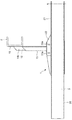
図5は従来の突入防止装置の構成を示す平面図、図6は正面図、図7は側面図である。図5〜図7に示すように、従来の突入防止装置50のバンパーステー51は、剛性を確保するため、平板52の車体前後方向端部を車体幅方向の外側に曲折してリブ53a,53bを形成した略コの字状断面を有するものである。また、バンパー54を固定する後端部付近にも、外側に板状の補強材55が設けられ、袋状に形成されている。バンパーステー51は、車体幅方向の左右両側でそれぞれ車体前後方向に沿って延びる左右一対のシャーシフレームFの外側にボルト56により固定されている。
FIG. 5 is a plan view showing the configuration of a conventional inrush prevention device, FIG. 6 is a front view, and FIG. 7 is a side view. As shown in FIGS. 5 to 7, the bumper stay 51 of the conventional
ところが、従来の突入防止装置のバンパーステー51では、リブ53a,53bや補強材55が設けられているものの、荷重を主にシャーシフレームFとバンパー54とを接続した平板52部分で受けるため、バンパー54の外側端部から平板52までの距離が遠く、バンパー54の外側荷重に対して変形が起こりやすい。また、このバンパーステー51では、平板52の面内荷重により座屈が起きやすいという問題がある。
However, in the bumper stay 51 of the conventional intrusion prevention device, although the
そこで、本発明においては、バンパーの外側荷重に対して変形が起こりにくい左右一対のバンパーステーを備えた突入防止装置を提供することを目的とする。 Accordingly, the present invention aims at providing a rush prevention apparatus provided with a bumper stearyl over deformation hardly occurs in the pair against the outer load of the bumper.
本発明の左右一対のバンパーステーは、車体幅方向の左右両側でそれぞれ車体前後方向に沿って延びる左右一対のシャーシフレームの外側にそれぞれ固定され、バンパーを支持する左右一対のバンパーステーであって、シャーシフレームの外側面に面接触してシャーシフレームに固定される平板状のフレーム取付部と、フレーム取付部に対して車体幅方向の外側に所定間隔で配置され、バンパーを支持する平板状のバンパー支持部と、フレーム取付部とバンパー支持部とを斜めに接続した平板状の接続部とを有するものである。 The pair of left and right bumper stays of the present invention are a pair of left and right bumper stays that are fixed to the outside of a pair of left and right chassis frames that extend along the vehicle body longitudinal direction on the left and right sides in the vehicle body width direction, respectively, and support the bumper. A flat frame mounting portion that is in surface contact with the outer surface of the chassis frame and is fixed to the chassis frame, and a flat bumper that is disposed at a predetermined interval on the outer side of the vehicle body width direction with respect to the frame mounting portion and supports the bumper It has a support part and the flat connection part which connected the frame attaching part and the bumper support part diagonally.
本発明のバンパーステーによれば、バンパーの外側荷重をシャーシフレームに固定されるフレーム取付部よりも外側に配置されたバンパー支持部により受けるとともに、フレーム取付部とバンパー支持部とを斜めに接続した接続部が補強リブとして機能するため、バンパーの外側荷重に対して変形が起こりにくくなる。また、フレーム取付部とバンパー支持部とを斜めに接続した接続部によって適度な変形を許容することによって、バンパーの支持に必要な強度と変形量を調節することが可能となる。 According to the bumper stay of the present invention, the outer load of the bumper is received by the bumper support portion arranged outside the frame attachment portion fixed to the chassis frame, and the frame attachment portion and the bumper support portion are connected obliquely. Since the connecting portion functions as a reinforcing rib, deformation hardly occurs with respect to the outer load of the bumper. Further, by allowing an appropriate deformation by the connecting portion in which the frame mounting portion and the bumper support portion are obliquely connected, it is possible to adjust the strength and the deformation amount necessary for supporting the bumper.
ここで、車体前後方向の両端部に、それぞれフレーム取付部から接続部を含んでバンパー支持部まで連続した補強リブを有することが望ましい。この補強リブにより、フレーム取付部とバンパー支持部とを斜めに接続した接続部の強度および変形量を調節することが可能となる。 Here, it is desirable to have reinforcing ribs that are continuous from the frame mounting portion to the bumper support portion at both ends in the longitudinal direction of the vehicle body. With this reinforcing rib, it is possible to adjust the strength and the amount of deformation of the connection portion in which the frame mounting portion and the bumper support portion are connected obliquely.
また、本発明の突入防止装置は、上記左右一対のバンパーステーと、左右一対のバンパーステーに支持されるバンパーであり、車体幅方向に延びるビームと、ビームの左右一対のバンパーステー側に固定され、左右一対のバンパーステー間に延びる取付部とを有するバンパーと備えたものである。 The intrusion prevention device of the present invention is a bumper supported by the pair of left and right bumper stays and the pair of left and right bumper stays, and is fixed to the beam extending in the vehicle body width direction and the pair of left and right bumper stays of the beam. And a bumper having a mounting portion extending between the pair of left and right bumper stays.
これにより、左右一対のシャーシフレームの外側のタイヤ後方の架装スペースを減らすことなく、バンパーステー間のバンパーの強度を上げることができる。 Thereby, the intensity | strength of the bumper between bumper stays can be raised, without reducing the mounting space behind the tire of the outer side of a pair of left and right chassis frames.
(1)シャーシフレームの外側面に面接触してシャーシフレームに固定される平板状のフレーム取付部と、フレーム取付部に対して車体幅方向の外側に所定間隔で配置され、バンパーを支持する平板状のバンパー支持部と、フレーム取付部とバンパー支持部とを斜めに接続した平板状の接続部とを有するバンパーステーにより、バンパーの外側荷重に対して変形が起こりにくくなり、突入防止装置の軽量化を図ることができる。また、バンパーステーの外側面が平板状のバンパー支持部の平面となるため、外観が良く、バックランプやナンバープレート等のステーの取り付け等も容易である。また、バンパーステーの外側面が平面であることに加えて、フレーム取付部とバンパー支持部との接続部も斜めに接続した平板状であるため、バンパーステーへ土砂が堆積しにくい。さらに、フレーム取付部とバンパー支持部とを斜めに接続した接続部によって適度な変形を許容し、バンパーの支持に必要な強度と変形量を調節することが可能となるため、バンパーが大きな荷重を受けた際のシャーシフレームへの影響を少なくすることが可能となる。 (1) A flat frame mounting portion that comes into surface contact with the outer surface of the chassis frame and is fixed to the chassis frame, and a flat plate that is disposed at a predetermined interval on the outer side in the vehicle body width direction with respect to the frame mounting portion and supports the bumper Bumper stays that have a flat bumper support and a flat connecting part that connects the frame mounting part and the bumper support part at an angle. Can be achieved. In addition, since the outer surface of the bumper stay is a flat surface of the flat bumper support portion, the appearance is good and it is easy to attach stays such as a back lamp and a license plate. In addition to the flat outer surface of the bumper stay, the connecting portion between the frame mounting portion and the bumper support portion has a flat plate shape that is obliquely connected, so that it is difficult for sediment to accumulate on the bumper stay. In addition, the joint that obliquely connects the frame mounting part and the bumper support part allows moderate deformation, and it is possible to adjust the strength and amount of deformation necessary to support the bumper. It is possible to reduce the influence on the chassis frame when received.
(2)上記左右一対のバンパーステーと、左右一対のバンパーステーに支持されるバンパーであり、車体幅方向に延びるビームと、ビームの左右一対のバンパーステー側に固定され、左右一対のバンパーステー間に延びる取付部とを有するバンパーとを備えた突入防止装置により、左右一対のシャーシフレームの外側のタイヤ後方の架装スペースを減らすことなく、バンパーステー間のバンパーの強度を上げることができる。また、タイヤ後方のバンパー上面の面積増加を抑えることができるため、バンパー上面への土砂の堆積量を少なくすることができる。 (2) A pair of left and right bumper stays and a bumper supported by the pair of left and right bumper stays. The beam extends in the vehicle body width direction, and is fixed to the pair of left and right bumper stays between the left and right bumper stays. With the intrusion prevention device including the bumper having the mounting portion extending to the front, the strength of the bumper between the bumper stays can be increased without reducing the mounting space behind the tire outside the pair of left and right chassis frames. Moreover, since the area increase of the bumper upper surface behind the tire can be suppressed, the amount of sediment deposited on the bumper upper surface can be reduced.
図1は本発明の実施の形態における突入防止装置の構成を示す斜視図、図2は平面図、図3は正面図、図4は側面図である。 FIG. 1 is a perspective view showing a configuration of a rush preventing device according to an embodiment of the present invention, FIG. 2 is a plan view, FIG. 3 is a front view, and FIG. 4 is a side view.
図1〜図4に示すように、本発明の実施の形態における突入防止装置1は、車体幅方向の左右両側でそれぞれ車体前後方向に沿って延びる左右一対のシャーシフレームFの外側にそれぞれ固定される左右一対のバンパーステー2a,2bと、バンパーステー2a,2bに支持されるバンパー3と、バンパーステー2a,2bとバンパー3とを連結するスペーサー4とから構成される。
As shown in FIGS. 1 to 4, the intrusion prevention device 1 according to the embodiment of the present invention is fixed to the outside of a pair of left and right chassis frames F extending along the longitudinal direction of the vehicle body on both the left and right sides in the vehicle body width direction. A pair of left and right bumper stays 2a, 2b, a
バンパーステー2a,2bは、シャーシフレームFの外側面に面接触してシャーシフレームFに固定される平板状のフレーム取付部10と、フレーム取付部10に対して車体幅方向の外側に所定間隔で配置され、バンパー3を支持する平板状のバンパー支持部11と、フレーム取付部10とバンパー支持部11とを連続的に斜めに接続した平板状の接続部12とを有する。なお、バンパーステー2aとバンパーステー2bとは、左右対称である。
The bumper stays 2a and 2b are in flat contact with the outer surface of the chassis frame F and fixed to the chassis frame F. The bumper stays 2a and 2b are spaced from the
フレーム取付部10は、シャーシフレームFの外側面と平行、すなわち車体前後上下方向に配置されている。バンパー支持部11はフレーム取付部10と平行に配置されており、その後方端部には、スペーサー4を取り付けるためのフランジ13が設けられている。フランジ13には、上下左右に複数の取付穴(図示せず。)が形成されており、スペーサー4とフランジ13とは、この取付穴を利用してボルト(図示せず。)により接合される。また、バンパーステー2a,2bの車体前後方向の両端部には、それぞれフレーム取付部10から接続部12を含んでバンパー支持部11まで連続した補強リブ14a,14bが設けられている。
The
また、車体幅方向の外側からみてバンパー支持部11および接続部12の裏側には、バンパー支持部11と平行に補強リブ15が設けられている。補強リブ15は車体後方斜め下を切り欠いた略凹形状である。補強リブ15は、フレーム取付部10と接続部12との接続部および補強リブ14a,14bに溶接されている。バンパー支持部11、接続部12および補強リブ14a,14b,15により囲まれた空間は、車体後方斜め下方向が開放されている。また、フランジ13の上端部には、水平方向の補強リブ16が設けられている。この補強リブ16は、バンパー支持部11、補強リブ14a,14b,15に溶接されている。
Reinforcing
バンパー3は、車体幅方向に延びるビーム20と、左右のバンパーステー2a,2b間に延びる取付部21と、スペーサー4に取り付けるためのフランジ22とから構成される。取付部21は、ビーム20の車輌前方側、すなわちバンパーステー2a,2b側に溶接固定されている。フランジ22には、上下左右に複数の取付穴22aが形成されており、スペーサー4とフランジ22とは、この取付穴22aを利用してボルト(図示せず。)により接合される。
The
上記構成の突入防止装置1は、フレーム取付部10に複数形成された取付穴を利用してボルト17によりシャーシフレームFに固定される。スペーサー4は、突入防止装置1を取り付ける車体に応じて長さが設定されており、所望の長さのものが用いられる。なお、スペーサー4を省略して、バンパーステー2a,2bにバンパー3を直接取り付けることもある。また、必要に応じてバンパー3を上昇または下降させる可倒式のスペーサーを用いることもある。
The rush preventing device 1 having the above configuration is fixed to the chassis frame F by
本実施形態における突入防止装置1では、バンパーステー2a,2bのバンパー支持部11の位置が、従来の突入防止装置50のバンパーステー51の平板52の位置よりも車体幅方向の外側にあり、これらのバンパーステー2a,2bが、バンパー3の外側荷重をシャーシフレームFに固定されるフレーム取付部10よりも外側に配置されたバンパー支持部11により受けるとともに、フレーム取付部10とバンパー支持部11とを斜めに接続した接続部12が補強リブとして機能するため、バンパー3の外側荷重に対して変形が起こりにくくなっており、突入防止装置1の軽量化を図ることができる。この斜めの接続部12は、フレーム取付部10のボルト17周りの補強としても機能する。また、バンパーステー2a,2bの外側面が平板状のバンパー支持部11の平面となっているため、外観が良く、バックランプやナンバープレート等のステーの取り付け等も容易である。また、バンパーステー2a,2bの外側面が平面であることに加えて、フレーム取付部10とバンパー支持部11との接続部12も斜めに接続した平板状であるため、バンパーステー2a,2bへ土砂が堆積しにくい。
In the intrusion prevention device 1 according to the present embodiment, the positions of the
また、このバンパーステー2a,2bでは、フレーム取付部10とバンパー支持部11とを斜めに接続した接続部12によって適度な変形を許容し、バンパー3の支持に必要な強度と変形量を調整することが可能であるため、バンパー3が大きな荷重を受けた際のシャーシフレームFへの影響を少なくすることができる。なお、本実施形態においては、補強リブ14a,14bにより、接続部12の強度と変形量を調節することが可能となっている。
Further, in the bumper stays 2a and 2b, moderate deformation is allowed by the connecting
また、本実施形態における突入防止装置1では、バンパー3の取付部21が左右のバンパーステー2a,2b間にあるので、シャーシフレームFの外側のタイヤ後方の架装スペースを減らすことなく、バンパーステー2a,2b間のバンパー3の強度が上がっており、バンパー3の外側荷重に対して変形が起こりにくい反面、バンパー3の中央側荷重に対して変形が起こりやすくなっている分をカバーしている。また、タイヤ後方のバンパー3上面の面積増加を抑えることができるため、バンパー3上面への土砂の堆積量が少なくなる。
Further, in the inrush prevention device 1 according to the present embodiment, since the mounting
本発明は、特装車やトラック等の車輌の後端部にバンパーを取り付けるための左右一対のバンパーステーを備えた突入防止装置として有用である。 The present invention is useful as a rush prevention apparatus having a pair of left and right bumper stearyl over for mounting the bumper on the rear end portion of a vehicle such as specially equipped vehicles and trucks.
F シャーシフレーム
1 突入防止装置
2a,2b バンパーステー
3 バンパー
4 スペーサー
10 フレーム取付部
11 バンパー支持部
12 接続部
13 フランジ
14a,14b,15,16 補強リブ
20 ビーム
21 取付部
22 フランジ
F Chassis frame 1
Claims (2)
前記シャーシフレームの外側面に面接触して前記シャーシフレームに固定される平板状のフレーム取付部と、
前記フレーム取付部に対して車体幅方向の外側に所定間隔で配置され、前記バンパーを支持する平板状のバンパー支持部と、
前記フレーム取付部と前記バンパー支持部とを斜めに接続した平板状の接続部と
を有する左右一対のバンパーステーと、
前記左右一対のバンパーステーに支持されるバンパーであり、前記車体幅方向に延びるビームと、前記ビームの前記左右一対のバンパーステー側に固定され、前記左右一対のバンパーステー間に延びる取付部とを有するバンパーと
を備えた突入防止装置。 A pair of left and right bumper stays that are fixed to the outside of a pair of left and right chassis frames extending along the longitudinal direction of the vehicle body on both the left and right sides in the vehicle body width direction, and support the bumper,
A plate-shaped frame mounting portion fixed to the chassis frame in surface contact with the outer surface of the chassis frame;
A flat bumper support portion that is disposed at a predetermined interval on the outer side in the vehicle body width direction with respect to the frame mounting portion, and supports the bumper;
A pair of left and right bumper stays having a flat plate-like connecting portion that obliquely connects the frame mounting portion and the bumper support portion ;
A bumper supported by the pair of left and right bumper stays; a beam extending in the vehicle body width direction; and a mounting portion fixed to the pair of left and right bumper stays of the beam and extending between the pair of left and right bumper stays. With bumper
Inrush prevention device with
Priority Applications (1)
| Application Number | Priority Date | Filing Date | Title |
|---|---|---|---|
| JP2012094377A JP5847641B2 (en) | 2012-04-18 | 2012-04-18 | Inrush prevention device |
Applications Claiming Priority (1)
| Application Number | Priority Date | Filing Date | Title |
|---|---|---|---|
| JP2012094377A JP5847641B2 (en) | 2012-04-18 | 2012-04-18 | Inrush prevention device |
Publications (2)
| Publication Number | Publication Date |
|---|---|
| JP2013220765A JP2013220765A (en) | 2013-10-28 |
| JP5847641B2 true JP5847641B2 (en) | 2016-01-27 |
Family
ID=49592055
Family Applications (1)
| Application Number | Title | Priority Date | Filing Date |
|---|---|---|---|
| JP2012094377A Active JP5847641B2 (en) | 2012-04-18 | 2012-04-18 | Inrush prevention device |
Country Status (1)
| Country | Link |
|---|---|
| JP (1) | JP5847641B2 (en) |
Families Citing this family (2)
| Publication number | Priority date | Publication date | Assignee | Title |
|---|---|---|---|---|
| JP6942010B2 (en) * | 2017-09-04 | 2021-09-29 | 三菱アルミニウム株式会社 | Mounting structure of vehicle exterior members |
| JP7330127B2 (en) | 2020-03-31 | 2023-08-21 | 極東開発工業株式会社 | cargo handling vehicle |
Family Cites Families (1)
| Publication number | Priority date | Publication date | Assignee | Title |
|---|---|---|---|---|
| JP4512461B2 (en) * | 2004-09-24 | 2010-07-28 | プレス工業株式会社 | Underrun protector |
-
2012
- 2012-04-18 JP JP2012094377A patent/JP5847641B2/en active Active
Also Published As
| Publication number | Publication date |
|---|---|
| JP2013220765A (en) | 2013-10-28 |
Similar Documents
| Publication | Publication Date | Title |
|---|---|---|
| JP6160464B2 (en) | Front body structure of the vehicle | |
| JP6228174B2 (en) | Body front structure | |
| US8870224B2 (en) | Engine cradle with deflector device | |
| JP5952211B2 (en) | Car body rear structure | |
| US20180186410A1 (en) | Utility vehicle | |
| JP5637478B2 (en) | Vehicle front structure | |
| JP4811327B2 (en) | Automobile fender panel support structure | |
| JP6163417B2 (en) | Structure of the underrun protector | |
| CN109415095B (en) | Bottom structure of cab | |
| JP5847641B2 (en) | Inrush prevention device | |
| JP6243717B2 (en) | Structure of the underrun protector | |
| JP5966881B2 (en) | Automobile leg mounting structure | |
| JP2011016404A (en) | Mounting structure for towing hook bracket | |
| JP4905675B2 (en) | Body structure at the front of the vehicle | |
| JP2013144484A (en) | Vehicle body frame reinforcing structure | |
| JP5958706B2 (en) | Body structure at the front of the vehicle | |
| JP6091876B2 (en) | Car suspension member reinforcement structure | |
| JP5913885B2 (en) | Rear suspension structure of automobile | |
| JP7048532B2 (en) | Subframe structure | |
| JP6020932B2 (en) | Auto body structure | |
| JP2018154210A (en) | Underrun protector | |
| JP6356959B2 (en) | Structure of the underrun protector | |
| JP4327512B2 (en) | Connection structure of radiator support | |
| JP2020199987A (en) | Sensor mounting structure | |
| JP6603578B2 (en) | Suspension member reinforcement structure |
Legal Events
| Date | Code | Title | Description |
|---|---|---|---|
| A621 | Written request for application examination |
Free format text: JAPANESE INTERMEDIATE CODE: A621 Effective date: 20141015 |
|
| A977 | Report on retrieval |
Free format text: JAPANESE INTERMEDIATE CODE: A971007 Effective date: 20150826 |
|
| A131 | Notification of reasons for refusal |
Free format text: JAPANESE INTERMEDIATE CODE: A131 Effective date: 20150901 |
|
| A521 | Request for written amendment filed |
Free format text: JAPANESE INTERMEDIATE CODE: A523 Effective date: 20151014 |
|
| TRDD | Decision of grant or rejection written | ||
| A01 | Written decision to grant a patent or to grant a registration (utility model) |
Free format text: JAPANESE INTERMEDIATE CODE: A01 Effective date: 20151117 |
|
| A61 | First payment of annual fees (during grant procedure) |
Free format text: JAPANESE INTERMEDIATE CODE: A61 Effective date: 20151125 |
|
| R150 | Certificate of patent or registration of utility model |
Ref document number: 5847641 Country of ref document: JP Free format text: JAPANESE INTERMEDIATE CODE: R150 |
|
| R250 | Receipt of annual fees |
Free format text: JAPANESE INTERMEDIATE CODE: R250 |
|
| R250 | Receipt of annual fees |
Free format text: JAPANESE INTERMEDIATE CODE: R250 |
|
| R250 | Receipt of annual fees |
Free format text: JAPANESE INTERMEDIATE CODE: R250 |
|
| R250 | Receipt of annual fees |
Free format text: JAPANESE INTERMEDIATE CODE: R250 |
|
| R250 | Receipt of annual fees |
Free format text: JAPANESE INTERMEDIATE CODE: R250 |
|
| R250 | Receipt of annual fees |
Free format text: JAPANESE INTERMEDIATE CODE: R250 |