JP6187562B2 - DATA STORAGE MEDIUM, DATA READING DEVICE, AND DATA READING METHOD - Google Patents
DATA STORAGE MEDIUM, DATA READING DEVICE, AND DATA READING METHOD Download PDFInfo
- Publication number
- JP6187562B2 JP6187562B2 JP2015186065A JP2015186065A JP6187562B2 JP 6187562 B2 JP6187562 B2 JP 6187562B2 JP 2015186065 A JP2015186065 A JP 2015186065A JP 2015186065 A JP2015186065 A JP 2015186065A JP 6187562 B2 JP6187562 B2 JP 6187562B2
- Authority
- JP
- Japan
- Prior art keywords
- data
- unit
- image data
- pattern
- physical structure
- Prior art date
- Legal status (The legal status is an assumption and is not a legal conclusion. Google has not performed a legal analysis and makes no representation as to the accuracy of the status listed.)
- Active
Links
Images


Description
本発明は、データ保存媒体、データ読出装置及びデータ読出方法に関する。 The present invention relates to a data storage medium, a data reading device, and a data reading method.
種々の情報を記録する媒体としての紙は、古くから利用されており、現在においても、多くの情報が紙面上に記録されている。一方、産業の発達とともに、動画、静止画等の画像情報を記録するフィルム(マイクロフィルム等)、音の情報を記録するレコード盤等が利用され、近年では、デジタルデータを記録する媒体として、CD、DVD、光カード等の光学式に読込可能な記録媒体等が利用されている。 Paper as a medium for recording various information has been used for a long time, and even now, a lot of information is recorded on paper. On the other hand, with the development of the industry, films (microfilm, etc.) for recording image information such as moving images and still images, record boards for recording sound information, etc. have been used. In recent years, CDs have been used as media for recording digital data. In addition, optically readable recording media such as DVDs and optical cards are used.
CD、DVD等の記録媒体においては、読出装置の回転ステージにセットされた記録媒体を一定方向に回転させながらレーザ光を記録媒体表面に照射し、記録媒体表面の凹凸構造によって変化する反射光を検出することで、記録されている情報が読み出される。また、光カードにおいても同様に、読出装置に挿入された記録媒体に光を照射し、記録媒体に形成された孔部と非孔部との反射率のコントラストを検出することで、記録された情報が読み出される。これらの記録媒体に記録された情報を読み出すためには、CD、DVD等の表裏面、光カードの挿入方向など、読出装置に記録媒体を正しい位置でセットする必要がある。そして、これらの記録媒体に記録された情報を読み出す読出装置においては、記録媒体が正しい位置でセットされていることを前提として、情報を読み出す方向が設定されている。通常、CD、DVD等の記録媒体においては、記録媒体の基材とは異なる材料からなるレーベル面が記録媒体の一方面に形成されており、光カード等の記録媒体においては挿入方向を示すマークが印刷されている(光カードに関し、特許文献1参照)。これらのレーベル面やマークを作業者が確認することで、読出装置に正しい位置で媒体をセットすることができる。
In a recording medium such as a CD or DVD, the surface of the recording medium is irradiated with laser light while rotating the recording medium set on the rotary stage of the reading device in a certain direction, and reflected light that varies depending on the uneven structure on the surface of the recording medium. By detecting, the recorded information is read out. Similarly, in the optical card, the recording medium inserted in the reading device is irradiated with light, and the recording is performed by detecting the contrast of the reflectance between the hole portion and the non-hole portion formed in the recording medium. Information is read. In order to read the information recorded on these recording media, it is necessary to set the recording medium at the correct position on the reading device, such as the front and back surfaces of CDs, DVDs, etc., and the insertion direction of the optical card. And in the reading apparatus which reads the information recorded on these recording media, the direction which reads information is set on the assumption that the recording medium is set in the correct position. Usually, in a recording medium such as a CD or DVD, a label surface made of a material different from the base material of the recording medium is formed on one surface of the recording medium. In a recording medium such as an optical card, a mark indicating the insertion direction Is printed (refer to
近年、上記記録媒体として、100年を超える超長期に亘って情報を安定的に保存可能なものが求められている。上記CD、DVD等のように、記録媒体を構成する基材とは異なる材料からなるレーベル面を有する場合、そのレーベル面を構成する材料が記録媒体の基材を構成する材料よりも環境変化に弱く、また熱応力等により記録媒体を構成する基材に対して応力が加わること等により記録媒体の寿命が制限されてしまい、超長期的に情報を安定的に保存することが困難であるという問題がある。 In recent years, there has been a demand for a recording medium capable of stably storing information over an ultra-long period exceeding 100 years. In the case of having a label surface made of a material different from the base material constituting the recording medium, such as the above-described CD, DVD, etc., the material constituting the label surface is more susceptible to environmental changes than the material constituting the base material of the recording medium. It is weak and the life of the recording medium is limited due to the stress applied to the base material constituting the recording medium due to thermal stress, etc., and it is difficult to stably store information for an ultra long period of time. There's a problem.
このような問題を解消すべく、CD、DVD等の記録媒体にレーベル面を設けないようにすると、記録媒体の表裏を認識することが困難となる。読出装置に記録媒体が誤った方向で装着されてしまうと、読出装置において定められた読み出し方向と、記録媒体に記録されている情報の配列方向とが一致せず、正しい情報を読み出すことができないという問題が生じ得る。 If no label surface is provided on a recording medium such as a CD or DVD in order to solve such a problem, it becomes difficult to recognize the front and back of the recording medium. If the recording medium is loaded in the reading device in the wrong direction, the reading direction determined by the reading device does not match the arrangement direction of the information recorded on the recording medium, and correct information cannot be read. The problem can arise.
また、上記光カードのように、挿入方向を示すマークが印刷されている場合、超長期に亘って保管されたときに、その保管環境等によっては当該マークが消失してしまい、光カードの挿入方向を認識することが困難となるという問題がある。 In addition, when a mark indicating the insertion direction is printed as in the case of the optical card, when the mark is stored for an extremely long time, the mark may disappear depending on the storage environment, etc. There is a problem that it is difficult to recognize the direction.
このような課題に鑑みて、本発明は、超長期に亘って保管される場合であっても、記録されている情報の読出方向を容易に認識可能なデータ保存媒体、データ読出装置及びデータ読出方法を提供することを目的とする。 In view of such problems, the present invention provides a data storage medium, a data reading device, and a data reading device that can easily recognize the reading direction of recorded information even when stored for an extremely long period of time. It aims to provide a method.
上記課題を解決するために、本発明は、データが保存されてなるデータ保存媒体であって、第1面及び当該第1面に対向する第2面を有する、石英からなる基材と、前記基材の前記第1面上に定義された方形状の保存領域内に形成されてなり、前記データのデータビット列を、当該データビット列の各ビットに対応する物理的構造により表現するデータパターンと、前記基材の前記第1面上に前記保存領域に対応するようにして設けられてなり、前記保存領域に形成されている前記データパターンの前記物理的構造により表現されている前記データビット列の配列方向に関する情報を示す配列方向指標マークとを備え、前記配列方向指標マークは、前記データパターンの前記物理的構造により表現されている前記データビット列の配列方向を特定可能な位置に設けられていることを特徴とするデータ保存媒体を提供する(発明1)。 In order to solve the above-described problems, the present invention provides a data storage medium in which data is stored, and includes a base material made of quartz having a first surface and a second surface facing the first surface; A data pattern formed in a rectangular storage region defined on the first surface of the substrate, and representing a data bit string of the data by a physical structure corresponding to each bit of the data bit string; An array of the data bit strings that are provided on the first surface of the base material so as to correspond to the storage area and are expressed by the physical structure of the data pattern formed in the storage area An array direction indicator mark indicating information about the direction, the array direction indicator mark indicates the array direction of the data bit string represented by the physical structure of the data pattern. Providing data storage medium, characterized in that provided in a fixed position capable (invention 1).
上記発明(発明1)によれば、データパターンを構成する物理的構造が、保存されているデータのデータビット列の配列方向に対応して配列されており、当該物理的構造により表現されているデータビット列の配列方向に関する情報を示す配列方向指標マークが、当該データビット列の配列方向を特定可能な位置に設けられていることで、超長期に亘って保管される場合であっても、保存されている情報の読出方向を容易に認識することができる。 According to the said invention (invention 1), the physical structure which comprises a data pattern is arranged corresponding to the arrangement direction of the data bit sequence of the preserve | saved data, and the data represented by the said physical structure Even when the data bit string is stored for an extremely long period of time, the arrangement direction index mark indicating information related to the bit string arrangement direction is provided at a position where the arrangement direction of the data bit string can be specified. It is possible to easily recognize the reading direction of the information.
上記発明(発明1)において、前記基材の前記第1面上には、行列状に配置された複数の前記保存領域が定義されており、前記複数の保存領域のそれぞれには、前記データを複数に分割して得られる複数の単位データのそれぞれのデータビット列を、当該データビット列の各ビットに対応する単位物理的構造により表現する単位データパターンが形成されており、前記配列方向指標マークは、前記複数の保存領域のそれぞれに対応するようにして、前記複数の保存領域のそれぞれに形成されている前記単位データパターンの前記単位物理的構造により表現されている前記単位データのデータビット列の配列方向を特定可能な位置に設けられているのが好ましい(発明2)。 In the above invention (invention 1), the said first surface before Kimoto material, a plurality of the storage regions arranged in a matrix are defined, to each of the plurality of storage areas, the data A unit data pattern that represents each data bit string of a plurality of unit data obtained by dividing the data into a plurality of unit data by a unit physical structure corresponding to each bit of the data bit string is formed. An array of data bit strings of the unit data represented by the unit physical structure of the unit data pattern formed in each of the plurality of storage areas so as to correspond to each of the plurality of storage areas It is preferable to be provided at a position where the direction can be specified (Invention 2).
上記発明(発明1,2)において、前記保存領域と前記配列方向指標マークとの全体形状が対称性を有しないような位置に前記配列方向指標マークが設けられているのが好ましい(発明3)。
In the above inventions (
上記発明(発明1〜3)において、前記配列方向指標マークが、前記保存領域の外側の領域に設けられていてもよいし(発明4)、前記保存領域内に設けられていてもよい(発明5)。 In the said invention (invention 1-3), the said arrangement | positioning direction index mark may be provided in the area | region outside the said storage area (invention 4), and may be provided in the said storage area (invention). 5).
上記発明(発明1〜5)において、前記物理的構造は、前記データビット列の各ビットに対応する凹部及び凸部により構成され得るものであって(発明6)、前記配列方向指標マークは、凹部又は凸部により構成され得る(発明7)。
In the above inventions (
また、上記発明(発明1〜5)において、前記物理的構造は、前記データビット列の各ビットに対応する貫通孔及び非孔部により構成され得るものであって(発明8)、前記配列方向指標マークは、貫通孔又は非孔部により構成され得る(発明9)。
In the inventions (
また、本発明は、上記発明(発明1〜9)に係るデータ保存媒体に保存されているデータを読み出す装置であって、前記データ保存媒体が載置される媒体載置部と、前記媒体載置部に載置された前記データ保存媒体の前記保存領域を含む領域の画像データを取得する画像データ取得部と、前記画像データ取得部により取得された前記画像データから、前記保存領域に形成されている前記データパターンの物理的構造を抽出する方向を決定する抽出方向決定部と、前記抽出方向決定部により決定された前記物理的構造の抽出方向に従って前記画像データから前記物理的構造を抽出し、当該物理的構造から前記データを読み出すデータ読出部とを備え、前記抽出方向決定部は、前記画像データ取得部により取得された前記画像データから前記配列方向指標マークを認識し、当該配列方向指標マークの前記保存領域に対する位置関係に基づいて、前記物理的構造の抽出方向を決定することを特徴とするデータ読出装置を提供する(発明10)。
Further, the present invention is an apparatus for reading data stored in a data storage medium according to the above inventions (
上記発明(発明10)において、前記画像データ取得部は、前記配列方向指標マーク及び前記保存領域に形成されている前記データパターンを認識可能な画像データを取得してもよいし(発明11)、前記画像データ取得部は、前記配列方向指標マークを認識可能であるが、前記データパターンを認識不可能な第1画像データと、前記データパターンの前記物理的構造を認識可能な第2画像データとを取得し、前記抽出方向決定部は、前記第1画像データに基づいて前記物理的構造の抽出方向を決定し、前記画像データ取得部は、前記抽出方向決定部により決定された抽出方向に基づいて、前記データパターンの前記物理的構造を正位置にて表示する前記第2画像データを取得し、前記データ読出部は、前記第2画像データに基づいて前記物理的構造を抽出してもよい(発明12)。 In the above invention (Invention 10), the image data acquisition unit may acquire image data capable of recognizing the data pattern formed in the array direction index mark and the storage area (Invention 11), The image data acquisition unit is capable of recognizing the array direction index mark but not recognizing the data pattern; and second image data recognizing the physical structure of the data pattern; The extraction direction determining unit determines the extraction direction of the physical structure based on the first image data, and the image data acquiring unit is based on the extraction direction determined by the extraction direction determining unit. The second image data for displaying the physical structure of the data pattern in a normal position is acquired, and the data reading unit is configured to acquire the object based on the second image data. It may be extracted structures (invention 12).
さらに、本発明は、上記発明(発明1〜9)に係るデータ保存媒体に保存されているデータを読み出す方法であって、前記データ保存媒体の前記保存領域を含む領域の画像データを取得する画像データ取得工程と、前記画像データから、前記保存領域に形成されている前記データパターンの物理的構造を抽出する方向を決定する抽出方向決定工程と、前記抽出方向決定工程により決定された前記物理的構造の抽出方向に従って前記画像データから前記物理的構造を抽出し、当該物理的構造から前記データを読み出すデータ読出工程とを含み、前記抽出方向決定工程において、前記画像データから前記配列方向指標マークを認識し、当該配列方向指標マークの前記保存領域に対する位置関係に基づいて、前記物理的構造の抽出方向を決定することを特徴とするデータ読出方法を提供する(発明13)。
Furthermore, the present invention is a method for reading data stored in a data storage medium according to the above inventions (
上記発明(発明13)において、前記画像データ取得工程において、前記配列方向指標マーク及び前記保存領域に形成されている前記データパターンを認識可能な画像データを取得してもよいし(発明14)、前記画像データ取得工程は、前記配列方向指標マークを認識可能であるが、前記データパターンを認識不可能な第1画像データを取得する第1画像データ取得工程であり、前記抽出方向決定工程において、前記第1画像データに基づいて前記物理的構造の抽出方向を決定し、前記決定された抽出方向に基づいて、前記データパターンの前記物理的構造が正位置にて表示される前記データパターンの前記物理的構造を認識可能な前記第2画像データを取得する第2画像データ取得工程をさらに含み、前記データ読出工程において、前記第2画像データに基づいて前記物理的構造を抽出してもよい(発明15)。 In the above invention (Invention 13), in the image data acquisition step, image data capable of recognizing the data pattern formed in the array direction index mark and the storage area may be acquired (Invention 14), The image data acquisition step is a first image data acquisition step of acquiring first image data capable of recognizing the arrangement direction indicator mark but not of the data pattern, and in the extraction direction determination step, Determining an extraction direction of the physical structure based on the first image data, and based on the determined extraction direction, the physical structure of the data pattern is displayed at a normal position in the data pattern; A second image data acquisition step of acquiring the second image data capable of recognizing a physical structure, and in the data reading step, It may be extracted the physical structure on the basis of the second image data (invention 15).
本発明によれば、超長期に亘って保管される場合であっても、記録されている情報の読出方向を容易に認識可能なデータ保存媒体、データ読出装置及びデータ読出方法を提供することができる。 According to the present invention, it is possible to provide a data storage medium, a data reading device, and a data reading method capable of easily recognizing the reading direction of recorded information even when stored for an extremely long period of time. it can.
本発明の実施の形態について、図面を参照しながら説明する。
[データ保存媒体]
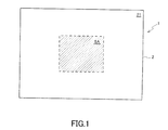
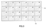
図1は、本実施形態に係るデータ保存媒体の概略構成を示す平面図であり、図2は、本実施形態における単位保存領域の概略構成を示す平面図であり、図3は、本実施形態における保存領域を示す平面図であり、図4は、本実施形態に係るデータ保存媒体の部分拡大切断端面図であって、図2におけるI−I線切断端面図である。
Embodiments of the present invention will be described with reference to the drawings.
[Data storage medium]
FIG. 1 is a plan view illustrating a schematic configuration of a data storage medium according to the present embodiment, FIG. 2 is a plan view illustrating a schematic configuration of a unit storage area according to the present embodiment, and FIG. 3 illustrates the present embodiment. FIG. 4 is a partially enlarged cut end view of the data storage medium according to the present embodiment, which is a cut end view taken along the line II in FIG.
本実施形態に係るデータ保存媒体1は、第1面21及び当該第1面21に対向する第2面22を有し、略方形状の石英ガラスからなる基材2を備え、基材2の第1面21上に定義された略方形状の保存領域SA内に、保存されているデータのデータ内容(ビット列)の各ビットに対応する物理的構造により当該データのデータ内容(ビット列)を表現するデータパターンが形成されている。
The
保存領域SA内には、複数の単位保存領域UAがM行×N列(M及びNは、その一方が2以上の整数であり、他方が1以上の整数である。)の行列配置で並列されている。図3に示すように、本実施形態においては、24個の単位保存領域UAが4行(M=4)×6列(N=6)の行列配置で並列されている例を挙げて説明するが、この態様に限定されるものではない。 In the storage area SA, a plurality of unit storage areas UA are arranged in parallel in a matrix arrangement of M rows × N columns (one of M and N is an integer of 2 or more and the other is an integer of 1 or more). Has been. As shown in FIG. 3, in the present embodiment, an example in which 24 unit storage areas UA are arranged in parallel in a matrix arrangement of 4 rows (M = 4) × 6 columns (N = 6) will be described. However, it is not limited to this aspect.
保存領域SAは、複数の単位保存領域UAと、隣接する単位保存領域UAの間に位置する、畦道状のデータ非保存領域NAとを含む。各単位保存領域UAは、単位データパターン30が形成されている領域であり、データ非保存領域NAは、配列方向指標パターン40及び境界パターン50が形成されている領域である。
The storage area SA includes a plurality of unit storage areas UA and a saddle-shaped data non-storage area NA located between adjacent unit storage areas UA. Each unit storage area UA is an area in which the
単位保存領域UAの大きさは、後述する撮像部111における撮影可能領域の大きさ(単位保存領域UAに形成されている単位データパターン30の物理的構造(凹部31及び凸部32)を認識可能な倍率で撮影可能な領域の大きさ)に応じて適宜設定され得るものである。また、データ非保存領域NAの大きさは、少なくとも配列方向指標パターン40を形成可能な大きさである限り特に制限されないが、データ非保存領域NAの大きさを可能な限り小さくすることにより、保存領域SA中における単位保存領域UAの占める割合を増大させることができ、データの記録容量を大きくすることができる。このとき、データ非保存領域NAの幅WNAを、単位保存領域UA内の単位データパターン30の物理的構造(凹部31及び凸部32)の間隔の整数倍と不一致になるように設定するのが好ましい。これにより、データ非保存領域NAを明確に把握可能となる。
The size of the unit storage area UA can recognize the size of a shootable area in the imaging unit 111 (to be described later) (the physical structure of the
各単位保存領域UAに形成されている単位データパターン30は、データ保存媒体1に記録・保存されているデータが複数に分割された単位データのデータ内容(単位ビット列)を表現する凹部(ホール)31及び凸部(ホールが形成されていない部分)32からなる。本実施形態においては、当該単位データの単位ビット列のうちのビット「1」が凹部31と定義され、ビット「0」が凸部32と定義されている。例えば、図2においては、左上から右に向かって「1010011101・・・」という単位ビット列(単位ビット行列)で表現される単位データがデータ保存媒体1の単位保存領域UAに記録・保存されている。なお、単位ビット列のうちのビット「1」が凸部32と定義され、「0」が凹部31と定義されてもよい。
The
単位データパターン30としての凹部31及び凸部32は、行列状に配置されるようにして単位保存領域UA内に形成されており、当該凹部31及び凸部32の行列配置は、単位データの単位ビット列を行列配置に変換した単位ビット行列に対応する配置である。
The
データ保存媒体1に記録・保存されているデータの種類としては、特に限定されるものではなく、例えば、テキストデータ、動画や静止画等の画像データ、音声データ等が挙げられる。
The type of data recorded / stored in the
配列方向指標パターン40は、各単位保存領域UAに形成されている単位データパターン30(凹部31及び凸部32)により表現されている単位ビット列(単位ビット行列)の配列方向に関する情報を示すパターンであって、各単位保存領域UAに対応して設けられてなるものであって、物理的構造としての凹部41からなる。配列方向指標パターン40は、単位保存領域UAに形成されている単位データパターンUP(単位データの単位ビット列)の行列配置に関する情報を示すものである。図示例においては、配列方向指標パターン40は、長方形の単位保存領域UAの左上角部近傍及び左下角部近傍に形成されており、配列方向指標パターン40がこの位置に形成されている態様がデータ保存媒体1の正位置である。これを前提とすることで、単位データパターン30(凹部31及び凸部32)は、単位ビット列(単位ビット行列)に対応した行列配置(単位保存領域UAの左上から右下に向かう行列配置)で形成されている、と理解され得る。図5においては、単位データの単位ビット列の各ビットに対応する単位データパターン30(凹部31及び凸部32)が、矢印方向に配列されていることを示している。
The arrangement
配列方向指標パターン40は、各単位保存領域UAに形成されている単位データパターン30により表現されている単位ビット列(単位ビット行列)の配列方向を特定可能な位置に形成されていればよく、上記態様に限定されるものではない。配列方向指標パターン40は、単位保存領域UAと配列方向指標マークDPとにより構成される全体形状が、点対称、線対称、回転対称等の対称性を有しない形状となるような位置に形成されているのが好ましい。例えば、図6に示すように、単位保存領域UAの形状が略長方形状である場合、配列方向指標パターン40は、当該単位保存領域UAの4つの角部のうち、1つの角部(図6に示す例では左上の角部)の近傍であって、1つの辺(長辺又は短辺。図6に示す例では上側に位置する長辺)に沿って形成されていてもよい。配列方向指標パターン40がこのような位置に形成されていることで、後述するように、データ保存媒体1がデータ読出装置100にセットされたときに、保存領域SA(単位保存領域UA)がデータ読出装置100の撮像部111との位置関係で正位置であるか否かを容易に認識することができる。
The arrangement
なお、本実施形態における配列方向指標パターン40は、図7に示すように、データ保存媒体1の想定寿命や安定性を損なわない限りにおいて、酸化クロム等からなる金属薄膜等の基材2とは異なる部材により構成されていてもよい。また、配列方向指標パターン40の形状、寸法等は、特に限定されるものではないが、単位データパターン30を構成する物理的構造(凹部31及び凸部32)の形状や寸法と異なるのが好ましい。単位データパターン30と配列方向指標パターン40とを構成する物理的構造の形状や寸法が互いに相違することで、データ読出装置100の撮像部111により取得された画像データから、配列方向指標パターン40を容易に認識することができる。
In addition, as shown in FIG. 7, the arrangement
配列方向指標パターン40は、図8に示すように、単位保存領域UA内に形成されていてもよい。この場合においては、保存領域SA内にデータ非保存領域NAが存在していなくてもよい。これにより、データ保存媒体1における記録容量の増大が図れる。
As shown in FIG. 8, the array
本実施形態における単位データパターン30は、光学的に認識可能な物理的構造により構成されていればよく、凹部31及び凸部32に限定されるものではない。例えば、図9に示すように、単位ビット列のビット「1」に対応する貫通孔部33と、ビット「0」に対応する非孔部34とにより構成されていてもよい。この場合において、配列方向指標パターン40は、単位データパターン30と同様の物理的構造、すなわち貫通孔部により構成されているのが、データ保存媒体1の作製上の手間の観点から好ましい。一方で、単位データパターン30及び配列方向指標パターン40のいずれか一方が非貫通の凹部により構成され、他方が貫通孔部により構成されていてもよい。このような態様であれば、後述するデータ読出装置100(図18参照)の撮像部111にてデータ保存媒体1の第2面22側の画像データを取得した際、いずれか一方(単位データパターン30又は配列方向指標パターン40)の存在を確認することができないため、それによりデータ読出装置100にセットされたデータ保存媒体1の表裏が逆転していることを容易に認識することができる。
The
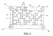
なお、配列方向指標パターン40は、各単位保存領域UAに形成されている単位データパターン30の配列方向に関する情報を示すものであるとともに、保存領域SA内における各単位保存領域UAの位置情報を示すものであってもよい。例えば、配列方向指標パターン40は、保存領域SA内に行列状に配置されている各単位保存領域UAの並列位置を表すp行目(pは1以上M以下の整数である。)及びq列目(qは1以上N以下の整数である。)という行番号及び列番号(p,q)の数字を表す点字を模したパターン(図10参照)を物理的構造(凹部41及び凸部42)により表現してなるものであってもよい。なお、図11においては、単位保存領域UAが04行02列目に位置する領域である、ということが配列方向指標パターン40により示されている。
The array
この場合において、配列方向指標パターン40は、単位データパターン30と同様、行番号及び列番号の数字を2値化したビット列を表す物理的構造(凹部41及び凸部42)により構成されていてもよい。
In this case, like the
境界パターン50は、一の単位保存領域UAと、行方向及び列方向においてデータ非保存領域NAを介して隣接する他の単位保存領域UAとの境界を示すパターンであって、略方形状の各単位保存領域UAの4角の外側に位置するように形成されている。かかる境界パターン50が形成されていることで、データ読出装置100の撮像部111にて各単位保存領域UAを容易に認識することが可能となり、複数の単位データパターン30として記録・保存されているデータの正確な読み出しが可能となる。
The
本実施形態において、境界パターン50は、略十字状であって、その交点Lから外側に向かって延伸する4つのパターン51〜54のうちの1つのパターン51の長さ(交点から当該パターンの延伸方向における長さ)が、他の3つのパターン52〜54の長さよりも短い(図12(a)参照)。このような形状を有する境界パターン50は、保存領域SA内の複数の単位保存領域UAの並列順(図3における左上から横方向に向かう順)に、90°ずつ回転させるようにして形成されている(図13参照)。後述するように、本実施形態に係るデータ保存媒体1に記録・保存されているデータを読み出す際に、各単位保存領域UAの画像データを、撮像部111をデータ保存媒体1に対して相対的に移動させながら取得する。そのため、撮像部111の移動のたびに撮像部111の位置合わせを行い、画像データを取得することになるが、単位保存領域UAの並列順に境界パターン50が90°ずつ回転していることで、撮像部111を走査させながら、単位保存領域UAの並列順に画像データを取得することができる。
In this embodiment, the
なお、境界パターン50は、その他の態様(平面視形状)として、略L字状(基準点Cpから2方向に延伸する、互いに直交する2つのパターンを有するもの)であってもよいし(図12(b)参照)、略十字状であって、基準点Cpから外側に延伸する4つのパターンの長さ(交点から当該パターンの延伸方向における長さ)が実質的に同一のものであってもよい(図12(c)参照)。
In addition, the
本実施形態において、単位データパターン30を構成する凹部31は、平面視略方形状のホール形状である。この凹部31の寸法は、一般的な撮像素子により凹部31を光学的に認識可能な寸法であればよいが、データ保存媒体1における記録・保存可能なデータ容量を増大させるために、単位データパターン30の凹部31の寸法は、例えば、400nm以下、好ましくは100〜250nm程度に設定され得る。
In the present embodiment, the
図14に示すように、単位データパターン30、配列方向指標パターン40及び境界パターン50は、いずれも、保存領域SA内に設定された仮想グリッドGrの交点PIに重なるようにして形成されている。より具体的には、単位データパターン30(凹部31)、配列方向指標パターン40及び境界パターン50のそれぞれの基準点Cpが仮想グリッドGrの交点PIに重なるように、単位データパターン30、配列方向指標パターン40及び境界パターン50が形成されている。ここで、単位データパターン30及び配列方向指標パターン40の基準点Cpは、単位データパターン30及び配列方向指標パターン40を構成する物理的構造の平面視における中心点であり、境界パターン50の基準点Cpは、略十字状の交点Lである。なお、少なくとも単位データパターン30の基準点Cpが仮想グリッドGrの交点PIに重なるようにして形成されていればよく、配列方向指標パターン40及び境界パターン50の基準点Cpは、仮想グリッドGrの交点PIに重なっていてもよいし、仮想グリッドGrのグリッド線に重なるが交点PIには重なっていなくてもよいし、仮想グリッドGrの交点PI及びグリッド線のいずれにも重なっていなくてもよい。
As shown in FIG. 14, the
上述した構成を有する本実施形態に係るデータ保存媒体1においては、記録・保存されているデータのデータ内容(ビット列)が、保存領域SAの各単位保存領域UAに形成されている単位データパターン30(行列状に配置された、物理的構造としての凹部31及び凸部32)により表現されている。そして、単位データパターン30における物理的構造(凹部31及び凸部32)の配置順の指標となる配列方向指標パターン40が、各単位保存領域UAに対応して形成されている。したがって、当該配列方向指標パターン40を認識することにより、データを読み出す順序を正確に認識することができ、当該データを正確に復元することができる。
In the
また、本実施形態に係るデータ保存媒体1は、石英からなる基材を加工することにより作製され得るものであって、極めて優れた耐熱性及び耐水性を有する。したがって、保存環境が変化したとしても記録・保存されているデータ(単位データパターン30)及び配列方向指標パターン40が滅失することがなく、当該データを超長期的に(数百年以上の単位で)保存することができるとともに、超長期的なスパンを経ても配列方向指標パターン40を認識することで、データ保存媒体1に保存されているデータを読み出す順序を正確認識し、当該データを正確に復元することができる。
The
さらに、本実施形態に係るデータ保存媒体1は、基材2の第1面21に形成されたデータパターン(物理的構造としての凹部31及び凸部32)によりデータを記録・保存することができるため、後述するように、当該データ保存媒体1を用いてインプリントリソグラフィ処理を行うことで、データが記録・保存されたデータ保存媒体1の複製物(バックアップ)を、当該データ(デジタルデータ)が存在していなくても容易に作製することができる。
Furthermore, the
さらにまた、本実施形態に係るデータ保存媒体1に記録・保存されているデータは、一般的な撮像素子を用いて光学的に認識可能な物理的構造により表現されているため、超長期的な将来においても、そのときに存在する撮像素子を用いて当該物理的構造(凹部31及び凸部32)を撮像してビット列に変換するだけで、容易にデータを復元することができる。
Furthermore, since the data recorded and stored in the
なお、本実施形態に係るデータ保存媒体1において、データが記録・保存される各単位保存領域UAの保存領域SA内における位置情報を示すものとしての配列方向指標パターン40が形成されている場合、データ保存媒体1に記録・保存されているデータの一部(複数の単位保存領域UAのうちの一部の単位保存領域UAに形成されている単位データパターン30)を読み出す場合であっても、当該配列方向指標パターン40に基づいて、目的とするデータ(データの一部)を容易に読み出すことができる。また、単位保存領域UAに形成されている物理的構造(凹部31)の一部が破損してしまった場合であっても、物理的構造の一部が破損してしまった単位保存領域UAを配列方向指標パターン40によって特定することができるため、データ保存媒体1の複製物(バックアップ)が予め作製されていれば、当該複製物から当該単位保存領域UAに記録・保存されているデータを容易に読み出すことができ、データ保存媒体1の他の単位保存領域UAから読み出されたデータと結合することで、データ保存媒体1に記録・保存されているデータの復元が可能となる。
In the
〔データ保存媒体の製造方法〕
上述した構成を有するデータ保存媒体1は、以下のようにして作製することができる。図15は、本実施形態に係るデータ保存媒体1を作製する前段階として描画データを設計する工程を概略的に示すフロー図であり、図16は、本実施形態に係るデータ保存媒体1を作製する工程を示す部分拡大斜視図である。
[Method of manufacturing data storage medium]
The
[描画データ設計工程]
まずは、データ保存媒体1に記録・保存されるデータDに基づき、データ保存媒体1の保存領域SA(各単位保存領域UA)に単位データパターン30及び配列方向指標パターン40を形成するための描画データを設計する。
[Drawing data design process]
First, drawing data for forming the
具体的には、まず、データDの全ビット列を、その先頭から所定のビット長単位でX個(Xは2以上の整数である。)の単位ビット列に分割し、当該単位ビット列を含む単位データUD1〜UDXを生成する。各単位データUDの単位ビット列のビット長は、単位保存領域UAに記録・保存可能なビット長と同一に設定され得る。本実施形態における各単位保存領域UAに8行×16列のビット行列でデータが保存され得る場合、記録・保存されるデータDの全ビット列を、その先頭から128ビット長の単位ビット列の単位データUDに分割する。なお、保存されるデータDの全ビット列を分割することなく一の単位保存領域UAに記録・保存可能であるならば、データDの全ビット列を分割しなくてもよい。 Specifically, first, all the bit strings of the data D are divided into X unit bit strings (X is an integer of 2 or more) from the head in a predetermined bit length unit, and unit data including the unit bit string is included. UD 1 to UD X are generated. The bit length of the unit bit string of each unit data UD can be set to be the same as the bit length that can be recorded and stored in the unit storage area UA. When data can be stored in a bit matrix of 8 rows × 16 columns in each unit storage area UA in this embodiment, all the bit strings of data D to be recorded / stored are unit data of unit bit strings of 128 bits from the beginning. Divide into UD. Note that it is not necessary to divide the entire bit string of data D if it can be recorded / saved in one unit storage area UA without dividing the entire bit string of stored data D.
次に、各単位データUDの単位ビット列を、8行×16列の単位ビット行列UMに変換し、当該単位ビット行列UMに基づいて、単位パターンデータD30を生成する。本実施形態においては、このとき、単位保存領域UAに相当する領域内に仮想グリッドGrを定義し、当該仮想グリッドGrの交点PIに重なるように、単位ビット行列UMのうちのビット「1」に対応する位置にのみ、凹部31に対応するビット図形(正方形の図形)を配置し、ビット「0」に対応する位置にはビット図形を配置しない(図15参照)。この単位パターンデータD30は、8行×16列の行列を構成する各位置におけるビット図形の有無によって、単位ビット行列UMを構成する128ビットの情報を表現している。この単位パターンデータD30が、単位保存領域UAに単位データパターン30(凹部31)を形成する際の描画データとして用いられる。
Next, the unit bit string of each unit data UD is converted into a unit bit matrix UM of 8 rows × 16 columns, and unit pattern data D 30 is generated based on the unit bit matrix UM. In the present embodiment, at this time, a virtual grid Gr is defined in an area corresponding to the unit storage area UA, and the bit “1” of the unit bit matrix UM is overlapped with the intersection point PI of the virtual grid Gr. Only in the corresponding position, the bit graphic (square graphic) corresponding to the
続いて、各単位パターンデータD30の外側(データ非保存領域NAであって、単位保存領域UAの左上角近傍及び左下角近傍)に配列方向指標パターンデータD40を付加する。この配列方向指標パターンデータD40が、データ非保存領域NAに配列方向指標パターン40を形成する際の描画データとして用いられる。
Subsequently, (a data non-conserved regions NA, the unit upper left corner and near the lower left corner near the conserved regions UA) outside of the unit pattern data D 30 adds the array direction indication pattern data D 40 to. The array direction indication pattern data D 40 is used as the drawing data for forming the array
このようにして各単位保存領域UAに形成される単位データパターン30の描画データである単位パターンデータD30、及びデータ非保存領域NAに形成される配列方向指標パターン40の描画データである配列方向指標パターンデータD40を生成した後、これらを行列状に配置するとともに、境界パターン50の描画データである境界パターンデータD50をデータ非保存領域NAに付加することで、描画データを生成することができる。
In this way, the unit pattern data D 30 which is the drawing data of the
なお、配列方向指標パターン40は、上記の順序で付加されなくてもよいし、上記以外の順序で付加された方がよい場合もある。例えば、図8に示すように、単位保存領域UA内に配列方向指標パターン40が設けられる場合には、単位保存領域UA内における配列方向指標パターン40の占める領域(配列方向指標パターン40を設けるために必要な仮想グリッドGrの交点PIの数)によって、単位保存領域UA内に配列可能な単位データUDのビット長に制約が生じる。このような場合には、配列方向指標パターンデータD40を生成した後、単位パターンデータD30を設計し、単位保存領域UAから配列方向指標パターン40が配置される領域を除いた個所(仮想グリッドGrの交点PI)に配列可能なビット長単位で、保存されるデータDの全データ列を分割するのが好ましい。
The arrangement
[データ保存媒体作製工程]
続いて、第1面11及び第1面11に対向する第2面12を有する、石英からなるデータ保存媒体用基材10を準備し、当該基材10の第1面11上に、単位データパターン30、配列方向指標パターン40及び境界パターン50に対応するレジストパターンR30,R40,R50を形成する(図16(a)参照)。
[Data storage medium production process]
Subsequently, a data
かかるレジストパターンR30,R40,R50は、半導体の製造プロセス等で利用されている従来公知の露光装置(電子線描画装置、レーザ描画装置等)を用いて形成され得る。この露光装置を用いて、上記のようにして生成された描画データに基づいて、データ保存媒体用基材10の第1面11側に形成されているレジスト層にパターン潜像を形成し、現像処理を施すことにより、レジストパターンR30,R40,R50を形成することができる。
Such resist patterns R 30 , R 40 , and R 50 can be formed using a conventionally known exposure apparatus (electron beam drawing apparatus, laser drawing apparatus, etc.) used in a semiconductor manufacturing process or the like. Using this exposure apparatus, based on the drawing data generated as described above, a pattern latent image is formed on the resist layer formed on the
上記レジスト層を構成する材料としては、特に限定されるものではなく、従来公知のエネルギー線感応型レジスト材料(例えば、電子線感応型レジスト材料等)等を用いることができる。なお、図16(a)に示す例においては、ポジ型のエネルギー線感応型レジスト材料を用いた例が示されているため、パターン潜像が形成されたレジスト層に現像処理を施すことで、凹状のレジストパターンR30,R40,R50が形成される。 The material constituting the resist layer is not particularly limited, and a conventionally known energy beam sensitive resist material (for example, electron beam sensitive resist material) can be used. In the example shown in FIG. 16 (a), an example using a positive type energy ray sensitive resist material is shown. Therefore, by performing development on the resist layer on which the pattern latent image is formed, Concave resist patterns R 30 , R 40 and R 50 are formed.
このようにしてレジストパターンR30,R40,R50を形成した後、当該レジストパターンR30,R40,R50をマスクとして用い、ウェットエッチング法又はドライエッチング法によりデータ保存媒体用基材10の第1面11をエッチングし(図16(b)参照)、残存するレジストパターンR30,R40,R50を除去する。これにより、基材2の第1面21に、単位データパターン30、配列方向指標パターン40及び境界パターン50が形成されてなる、本実施形態に係るデータ保存媒体1を作製することができる。なお、必要に応じて、データ保存媒体用基材10の第1面11側表面に酸化クロム等のハードマスク層が形成されているものを用い、レジストパターンR30,R40,R50をマスクとしたハードマスク層のエッチングによりハードマスクパターンを形成し、当該ハードマスクパターンをマスクとしてデータ保存媒体用基材10の第1面11をエッチングしてハードマスクパターンを除去することによりデータ保存媒体1を作製してもよい。
After forming the resist patterns R 30 , R 40 , R 50 in this way, the
このようにして作製されたデータ保存媒体1を用い、その複製物を作製する方法について説明する。図17は、本実施形態に係るデータ保存媒体1の複製物を作製する工程を切断端面にて示す工程フロー図である。
A method for producing a copy of the
まず、基材2の第1面21に単位データパターン30、配列方向指標パターン40及び境界パターン50が形成されてなるデータ保存媒体1と、第1面61及びそれに対向する第2面62を有し、第1面61上に樹脂層7が設けられてなる基板6とを準備する(図17(a)参照)。
First, the
基板6を構成する材料としては、特に限定されるものではなく、例えば、石英ガラス基板、ソーダガラス基板、蛍石基板、フッ化カルシウム基板、フッ化マグネシウム基板、アクリルガラス基板、ホウケイ酸ガラス基板等のガラス基板;ポリカーボネート基板、ポリプロピレン基板、ポリエチレン基板、その他ポリオレフィン基板等の樹脂基板等からなる単層基板や、上記基板のうちから任意に選択された2以上を積層してなる積層基板等が挙げられる。
The material constituting the
樹脂層7は、後述の工程(図17(b)参照)にて、データ保存媒体1の単位データパターン30、配列方向指標パターン40及び境界パターン50の反転パターンが形成される層である。樹脂層7を構成する樹脂材料としては、熱可塑性樹脂、熱硬化性樹脂、紫外線硬化性樹脂等の樹脂材料を用いることができ、より具体的には、アクリル系樹脂、スチレン系樹脂、オレフィン系樹脂、ポリカーボネート系樹脂、ポリエステル系樹脂、エポキシ系樹脂、シリコーン系樹脂等を用いることができる。
The
次に、基板6上の樹脂層7に、データ保存媒体1の第1面21を押し当てて、当該樹脂層7にデータ保存媒体1の単位データパターン30、配列方向指標パターン40及び境界パターン50を転写し、それらの反転パターンを形成する(図17(b)参照)。樹脂層7が硬化した後、当該樹脂層7からデータ保存媒体1及び基板6を剥離することで、樹脂製モールド8が作製される(図17(c)参照)。なお、後工程(図17(d)〜17(f))において支障がないのであれば、又は基板6と樹脂層7との密着性が高くそれらの剥離が困難であるならば、図17(c)に示す工程を省略し、基板6と樹脂層7とを剥離しなくてもよい。
Next, the
続いて、第1面11’及びそれに対向する第2面12’を有する、石英からなる複製物用基材10’を準備し、当該複製物用基材10’の第1面11’上にレジスト層9を形成し、当該レジスト層9に樹脂製モールド8における反転パターンが形成されている面を押し当て、その状態でレジスト層9を硬化させる(図17(d)参照)。
Subsequently, a
レジスト層9が硬化した後、樹脂製モールド8をレジスト層9から剥離することで、樹脂製モールド8の反転パターンが転写されたレジストパターン91が形成される(図17(e)参照)。そのレジストパターン91をマスクとして用いて、複製物用基材10の第1面11’をエッチングする。これにより、データ保存媒体1の複製物1’を作製することができる(図17(f)参照)。なお、レジスト層9の硬化に影響がない限りにおいて、必要に応じて、複製物用基材10’の第1面11’側表面に酸化クロム等のハードマスク層が形成されているものを用い、レジストパターン91をマスクとしたハードマスク層のエッチングによりハードマスクパターンを形成し、当該ハードマスクパターンをマスクとして複製物用基材10’の第1面11’をエッチングしてハードマスクパターンを除去することによりデータ保存媒体1の複製物1’を作製してもよい。
After the resist
上述したように、本実施形態によれば、半導体製造プロセス等で利用されている従来公知のリソグラフィ技術を利用することで、データ保存媒体1を容易に作製することができる。また、当該データ保存媒体1が破損した場合等に備え、それに記録・保存されているデータのバックアップとしての複製物は、従来公知のインプリント技術を利用して容易に作製され得る。
As described above, according to the present embodiment, the
〔データ読出装置・データ読出方法〕
上述した構成を有するデータ保存媒体1に記録・保存されたデータを読み出すためのデータ読出装置及び当該データ読出装置を用いたデータ読出方法について説明する。図18は、本実施形態におけるデータ読出装置の概略構成を示すブロック図である。
[Data reading device / data reading method]
A data reading apparatus for reading data recorded and stored in the
本実施形態におけるデータ読出装置100は、データ保存媒体1を載置(セット)するステージと、データ保存媒体1の保存領域SAの画像データを取得する画像データ取得部110と、当該画像データに基づいたデータ処理等を行う制御部121及び画像データ取得部110により取得された画像データや制御部121により生成された各種データ、各種プログラム等を記憶する記憶部122を有する制御装置120とを備える。なお、ステージには、画像データ取得部110に対する正位置でデータ保存媒体1をセットすることができるものの、画像データ取得部110に対して左に90°回転させた状態、右に90°回転させた状態、180°回転させた状態にてデータ保存媒体1をセットすることもできる。
The
画像データ取得部110は、CCDカメラのような所定の撮影対象領域内の画像を画像データとして取り込む撮像部111と、撮影対象領域がデータ保存媒体1の保存領域SAの各単位保存領域UAを撮影部111に対して順次相対的に移動させるように走査処理を行う走査部112とを含む。かかる画像データ取得部110としては、汎用の光学顕微鏡等を用いることができる。
The image
制御部121は、各種プログラムの指示に従って演算処理を行う。具体的には、制御部121は、各単位保存領域UAに形成されている単位データパターン30に基づいて画像データから単位データ(単位ビット列)を読み出す処理、当該単位データ(単位ビット列)の結合順序に関するデータ(結合順序データ)を生成する処理、配列方向指標パターン40に基づいて単位データパターン30に対応する単位データ(単位ビット列)の抽出方向を決定する処理、画像データ取得部110により取得された画像データや、種々の生成されたデータ等を記憶部122に記憶させる処理、読み出された単位データ(単位ビット列)を結合して、データ保存媒体1に記録・保存されているデータを復元する処理等を行う。
The
記憶部122は、画像データ取得部110により取得された保存領域SA(単位保存領域UA)の画像データ、単位保存領域UAに形成されている単位データパターン30に基づいて画像データから読み出された単位データ(単位ビット列)の結合順序データ等を記憶する。かかる制御部121及び記憶部122を有する制御装置120としては、汎用のコンピュータ等を用いることができる。
The
このような構成を有するデータ読出装置100を用いて、データ保存媒体1に記録・保存されているデータを読み出す方法について説明する。図19は、本実施形態におけるデータ読出方法の各工程を示すフローチャートである。
A method of reading data recorded / stored in the
まず、画像データ取得部110にデータ保存媒体1がセットされると、画像データ取得部110は、走査部112により、データ保存媒体1を撮像部111に対して相対的に移動させ、撮像部111により、データ保存媒体1の保存領域SAの各単位保存領域UAを所定の順で撮像させ、少なくとも単位保存領域UA及び配列方向指標パターン40の画像を含む画像データを取得する(S1)。単位保存領域UAの全体形状が長方形状であって、保存領域SA内にM行×N列(M≠N)の行列配置で単位保存領域UAが配列されている場合(図3参照)、画像データの取得前に、単位保存領域UAの全体形状を認識し、当該全体形状が横長の長方形状であれば、データ保存媒体1が正位置でセットされているか、正位置から180°回転した状態でセットされていると判断される。したがって、この場合には、M行×N列に対応して撮像部111を行方向に走査させてM×N個の画像データを取得すればよい。一方、単位保存領域UAの全体形状が縦長の長方形状であれば、データ保存媒体1が正位置から右又は左に90°回転した状態でセットされていると判断される。したがって、この場合には、N行×M列に対応して撮像部111を行方向に走査させてM×N個の画像データを取得すればよい。なお、単位保存領域UAの全体形状が正方形であって、保存領域SA内にM行×N列(M=N)の行列配置で単位保存領域UAが配列されている場合には、データ保存媒体1が正位置又はそれから180°回転した状態でセットされているか、正位置から右又は左に90°回転した状態でセットされているかを判断する必要はない。
First, when the
次に、制御部121は、記憶部122に記憶された各画像データの中から任意に選択された一の画像データの正位置に対する単位保存領域UAの位置関係を判断し、当該位置関係に基づいて単位保存領域UAに形成されている単位データパターン30の物理的構造(凹部31及び凸部32)を抽出する方向(抽出方向)を決定するとともに、各画像データから読み出され得る単位データ(単位ビット列)の結合順序を示す結合順序データを生成する(S2)。
Next, the
具体的には、図20に示すように、制御部121は、単位保存領域UA及びそれに対応する配列方向指標パターン40を物理的に包含する方形状の枠Frを定義し、当該枠Frを回転させながら、当該枠Fr内における配列方向指標パターン40の納まるべき位置Pと、画像データIMにおける配列方向指標パターン40とを一致させる。図20に示す例においては、上記のように一致させた枠Frが単位保存領域UAの正位置に対して左に90°回転していると判断することができる。したがって、制御部121は、画像データIMにおける単位保存領域UAに形成されている単位データパターン30が左下から右上に向かう行列状に配置されていると判断し、その行列配置に従って物理的構造(凹部31及び凸部32)の抽出方向を決定する。また、制御部121は、画像データを撮像順に行列状に配置したときに、左下に位置する画像データから列方向に沿って上方に向かう順で単位データを結合することを内容とする結合順序データが生成される。
Specifically, as shown in FIG. 20, the
続いて、制御部121は、上記のようにして決定された抽出方向に従い、記憶部122に記憶されている各画像データから、単位データパターン30の物理的構造(凹部31及び凸部32)を抽出し、当該物理的構造に基づいて単位データ(単位ビット列)を読み出し、当該単位データ(単位ビット列)を記憶部122に記憶させる(S3)。
Subsequently, the
単位データパターン30の物理的構造(凹部31及び凸部32)を抽出し、当該物理的構造に基づいて単位データ(単位ビット列)を読み出す際、制御部121は、単位保存領域UA、配列方向指標パターン40及び境界パターン50を含む画像データ上に仮想グリッドGrを定義する。この仮想グリッドGrは、4角に位置する境界パターン50の基準点Cpを通るように定義される。そして、制御部121は、単位保存領域UA内における仮想グリッドGrの各交点PI上に凹部31が存在するか否かを判定する。凹部31が存在するか否かの判定は、例えば、画像データにおける明暗分布に基づいて行われ得る。
When the physical structure (
制御部121は、凹部31が存在すると判定した交点PIにはビット「1」を、凹部31が存在しないと判定した交点PIにはビット「0」を対応付け、これにより単位データ(単位ビット列)が読み出される。
The
制御部121は、すべての画像データについて単位データ(単位ビット列)を記憶部122に記憶させた後(S3)、結合順序データに従って単位データ(単位ビット列)を結合し、データ(ビット列)を生成する(S4)。このようにして、データ保存媒体1に保存されているデータを復元することができる。
The
上述したように、本実施形態におけるデータ読出装置及びそれを用いたデータ読出方法によれば、データ保存媒体1に配列方向指標パターン40が設けられていることで、データ保存媒体1がデータ読出装置にセットされる方向にかかわらず、データ保存媒体1に保存されているデータを正確に復元することができる。
As described above, according to the data reading apparatus and the data reading method using the same in the present embodiment, the
以上説明した実施形態は、本発明の理解を容易にするために記載されたものであって、本発明を限定するために記載されたものではない。したがって、上記実施形態に開示された各要素は、本発明の技術的範囲に属する全ての設計変更や均等物をも含む趣旨である。 The embodiment described above is described for facilitating understanding of the present invention, and is not described for limiting the present invention. Therefore, each element disclosed in the above embodiment is intended to include all design changes and equivalents belonging to the technical scope of the present invention.
上記実施形態において、データ保存媒体1は、基材2の第1面21に定義された一の保存領域SA内に複数の単位保存領域UAが行列状に配置されてなるものであるが、本発明はこのような態様に限定されるものではなく、例えば、一の保存領域SA内に、データのビット列を表現するデータパターンが形成されてなるものであってもよい。
In the above embodiment, the
上記実施形態において、データ保存媒体1は、第1面11及びそれに対向する第2面12を有する、石英からなるデータ保存媒体用基材10の第1面11に、単位データパターン30、配列方向指標パターン40及び境界パターン50を同時に形成することで作製されるが(図16参照)、本発明はこのような態様に限定されるものではない。例えば、図21に示すように、第1面11’及びそれに対向する第2面12’を有する、石英からなる基材10’の第1面11’上に、複数の単位保存領域UA及びデータ非保存領域NAを含む保存領域SAが設定され、当該保存領域SAのデータ非保存領域NAに、各単位保存領域UAに対応する配列方向指標パターン40及び境界パターン50が形成されてなるデータ保存用媒体を準備し、当該データ保存用媒体の各単位保存領域UAに、単位データパターン30を形成することで、データ保存媒体1を作製してもよい。この場合において、当該データ保存用媒体の各単位保存領域UAに単位データパターン30を形成する際には、事前に配列方向指標パターン40を認識し、当該配列方向指標パターン40に基づいて、単位データパターン30を形成するために用いられる描画データである単位パターンデータD30を配置する。
In the above embodiment, the
上記実施形態に係るデータ保存媒体1において、単位データパターン30、配列方向指標パターン40及び境界パターン50を構成する物理的構造がドット状の凸部であってもよい。この場合において、当該データ保存媒体1を作製する際に、エネルギー線感応型レジスト材料としてネガ型の材料を用いればよい。
In the
上記実施形態において、データ読出装置100の画像データ取得部110により取得された画像データから単位データパターン30の物理的構造の抽出方向を決定し、当該抽出方向に従って物理的構造を抽出して単位データ(単位ビット列)を読み出しているが、本発明はこのような態様に限定されるものではない。例えば、画像データ取得部110により取得された画像データから、画像データの正位置に対する単位保存領域UAの位置関係を判断し、単位保存領域UAが画像データの正位置に一致していない場合には、画像データを回転させて正位置に戻し、左上から右下に向かう行列配置で物理的構造を抽出して単位データ(単位ビット列)を読み出してもよい。
In the above embodiment, the extraction direction of the physical structure of the
上記実施形態におけるデータ読出装置100及びデータ読出方法において、画像データ取得部110により、配列方向指標パターン40を認識可能であるが、単位データパターン30を認識不可能又は認識困難な第1画像データを取得し、当該第1画像データに基づいて、データ保存媒体1がセットされた方向(正位置であるか、正位置に対して左に90°、右に90°又は180°回転した状態であるか)を判断した後、単位データパターン30を認識可能な第2画像データを取得するようにしてもよい。この場合において、第1画像データとしては、複数の単位保存領域UAの中から任意に選択した一の単位保存領域UAを含む、1つの画像データを用いればよく、第2画像データを取得した後、データ保存媒体1がセットされた方向に従って、当該第2画像データを回転させて正位置に戻した画像データを記憶部122に記憶すればよい。これにより、制御部121においては、記憶部122に記憶されている画像データから、正位置であることを前提として単位データパターン30の物理的構造(凹部31及び凸部32)を抽出し、単位データ(単位ビット列)を読み出せばよい。
In the
上記実施形態におけるデータ読出装置100において、撮像部111にて撮像するにあたり、一の単位保存領域UAを含む、1つの画像データを取得し、当該画像データから配列方向指標パターン40に基づいて、データ保存媒体1が正しい方向でセットされているか否かを判断し、誤った方向でセットされていると判断される場合には、正しい方向でセットさせることを作業者に知らせるアラート機能を有していてもよい。
In the
上記実施形態においてデータを読み出すにあたり、データ保存媒体1が撮像部111に第1面21を対向させてセットされているか、第2面22を対向させてセットされているかを確認してもよい。撮像部111の焦点が、撮像部111に対向する第1面21に合わせられている場合、撮像部111に第2面22を対向させると、データ保存媒体1の基材2の厚さや撮像部111の焦点距離によっては、第1面21に形成されている単位データパターン30、配列方向指標パターン40を認識可能な画像データを取得することができなくなってしまう。そのため、データ保存媒体1が撮像部111に第1面21を対向させてセットされているか、第2面22を対向させてセットされているかを確認することで、第1面21に形成されている単位データパターン30、配列方向指標パターン40を認識可能な画像データを確実に取得することができる。
In reading the data in the above embodiment, it may be confirmed whether the
1…データ保存媒体
2…基材
21…第1面
22…第2面
30…単位データパターン
31…凹部
32…凸部
40…配列方向指標パターン
SA…保存領域
UA…単位保存領域
NA…データ非保存領域
Gr…仮想グリッド
PI…交点
DESCRIPTION OF
Claims (15)
第1面及び当該第1面に対向する第2面を有する、石英からなる基材と、
前記基材の前記第1面上に定義された方形状の保存領域内に形成されてなり、前記データのデータビット列を、当該データビット列の各ビットに対応する物理的構造により表現するデータパターンと、
前記基材の前記第1面上に前記保存領域に対応するようにして設けられてなり、前記保存領域に形成されている前記データパターンの前記物理的構造により表現されている前記データビット列の配列方向に関する情報を示す配列方向指標マークと
を備え、
前記配列方向指標マークは、前記データパターンの前記物理的構造により表現されている前記データビット列の配列方向を特定可能な位置に設けられていることを特徴とするデータ保存媒体。 A data storage medium in which data is stored,
A base material made of quartz, having a first surface and a second surface facing the first surface;
A data pattern formed in a rectangular storage area defined on the first surface of the substrate, and representing a data bit string of the data by a physical structure corresponding to each bit of the data bit string; ,
An array of the data bit strings that are provided on the first surface of the base material so as to correspond to the storage area and are expressed by the physical structure of the data pattern formed in the storage area An array direction indicator mark indicating information on the direction,
The data storage medium, wherein the array direction index mark is provided at a position where the array direction of the data bit string expressed by the physical structure of the data pattern can be specified.
前記複数の保存領域のそれぞれには、前記データを複数に分割して得られる複数の単位データのそれぞれのデータビット列を、当該データビット列の各ビットに対応する単位物理的構造により表現する単位データパターンが形成されており、
前記配列方向指標マークは、前記複数の保存領域のそれぞれに対応するようにして、前記複数の保存領域のそれぞれに形成されている前記単位データパターンの前記単位物理的構造により表現されている前記単位データのデータビット列の配列方向を特定可能な位置に設けられていることを特徴とする請求項1に記載のデータ保存媒体。 On the first surface of the front Kimoto material, a plurality of the storage regions arranged in a matrix are defined,
In each of the plurality of storage areas, a unit data pattern that represents each data bit string of a plurality of unit data obtained by dividing the data into a plurality of unit data by a unit physical structure corresponding to each bit of the data bit string Is formed,
The unit of arrangement direction index mark is represented by the unit physical structure of the unit data pattern formed in each of the plurality of storage areas so as to correspond to each of the plurality of storage areas The data storage medium according to claim 1, wherein the data storage medium is provided at a position where an arrangement direction of a data bit string of data can be specified.
前記データ保存媒体が載置される媒体載置部と、
前記媒体載置部に載置された前記データ保存媒体の前記保存領域を含む領域の画像データを取得する画像データ取得部と、
前記画像データ取得部により取得された前記画像データから、前記保存領域に形成されている前記データパターンの物理的構造を抽出する方向を決定する抽出方向決定部と、
前記抽出方向決定部により決定された前記物理的構造の抽出方向に従って前記画像データから前記物理的構造を抽出し、当該物理的構造から前記データを読み出すデータ読出部と
を備え、
前記抽出方向決定部は、前記画像データ取得部により取得された前記画像データから前記配列方向指標マークを認識し、当該配列方向指標マークの前記保存領域に対する位置関係に基づいて、前記物理的構造の抽出方向を決定することを特徴とするデータ読出装置。 An apparatus for reading data stored in the data storage medium according to claim 1,
A medium placement unit on which the data storage medium is placed;
An image data acquisition unit for acquiring image data of an area including the storage area of the data storage medium placed on the medium placement part;
An extraction direction determination unit that determines a direction in which a physical structure of the data pattern formed in the storage area is extracted from the image data acquired by the image data acquisition unit;
A data reading unit that extracts the physical structure from the image data according to the extraction direction of the physical structure determined by the extraction direction determination unit, and reads the data from the physical structure;
The extraction direction determination unit recognizes the arrangement direction index mark from the image data acquired by the image data acquisition unit, and based on the positional relationship of the arrangement direction index mark with respect to the storage area, A data reading apparatus characterized by determining an extraction direction.
前記抽出方向決定部は、前記第1画像データに基づいて前記物理的構造の抽出方向を決定し、
前記画像データ取得部は、前記抽出方向決定部により決定された抽出方向に基づいて、前記データパターンの前記物理的構造を正位置にて表示する前記第2画像データを取得し、
前記データ読出部は、前記第2画像データに基づいて前記物理的構造を読み出す
ことを特徴とする請求項10に記載のデータ読出装置。 The image data acquisition unit is capable of recognizing the array direction index mark but not recognizing the data pattern; and second image data recognizing the physical structure of the data pattern; Get
The extraction direction determining unit determines an extraction direction of the physical structure based on the first image data;
The image data acquisition unit acquires the second image data that displays the physical structure of the data pattern in a normal position based on the extraction direction determined by the extraction direction determination unit,
The data reading device according to claim 10, wherein the data reading unit reads the physical structure based on the second image data.
前記データ保存媒体の前記保存領域を含む領域の画像データを取得する画像データ取得工程と、
前記画像データから、前記保存領域に形成されている前記データパターンの物理的構造を抽出する方向を決定する抽出方向決定工程と、
前記抽出方向決定工程により決定された前記物理的構造の抽出方向に従って前記画像データから前記物理的構造を抽出し、当該物理的構造から前記データを読み出すデータ読出工程と
を含み、
前記抽出方向決定工程において、前記画像データから前記配列方向指標マークを認識し、当該配列方向指標マークの前記保存領域に対する位置関係に基づいて、前記物理的構造の抽出方向を決定することを特徴とするデータ読出方法。 A method for reading data stored in the data storage medium according to claim 1,
An image data acquisition step of acquiring image data of an area including the storage area of the data storage medium;
An extraction direction determining step for determining a direction from which the physical structure of the data pattern formed in the storage area is extracted from the image data;
A data reading step of extracting the physical structure from the image data according to the extraction direction of the physical structure determined by the extraction direction determining step, and reading the data from the physical structure;
In the extraction direction determination step, the arrangement direction index mark is recognized from the image data, and the extraction direction of the physical structure is determined based on a positional relationship of the arrangement direction index mark with respect to the storage area. To read data.
前記抽出方向決定工程において、前記第1画像データに基づいて前記物理的構造の抽出方向を決定し、
前記決定された抽出方向に基づいて、前記データパターンの前記物理的構造が正位置にて表示される、前記データパターンの前記物理的構造を認識可能な第2画像データを取得する第2画像データ取得工程をさらに含み、
前記データ読出工程において、前記第2画像データに基づいて前記物理的構造を読み出すことを特徴とする請求項14に記載のデータ読出方法。 The image data acquisition step is a first image data acquisition step of acquiring first image data that can recognize the array direction indicator mark but cannot recognize the data pattern;
In the extraction direction determination step, the extraction direction of the physical structure is determined based on the first image data,
Second image data for acquiring second image data capable of recognizing the physical structure of the data pattern, wherein the physical structure of the data pattern is displayed at a normal position based on the determined extraction direction. Further including an acquisition step,
15. The data reading method according to claim 14, wherein, in the data reading step, the physical structure is read based on the second image data.
Priority Applications (6)
| Application Number | Priority Date | Filing Date | Title |
|---|---|---|---|
| JP2015186065A JP6187562B2 (en) | 2015-09-18 | 2015-09-18 | DATA STORAGE MEDIUM, DATA READING DEVICE, AND DATA READING METHOD |
| PCT/JP2016/077407 WO2017047737A1 (en) | 2015-09-18 | 2016-09-16 | Data storage medium, method for manufacturing same, medium for data storage, data reading device, and data reading method |
| EP16846608.4A EP3352171A4 (en) | 2015-09-18 | 2016-09-16 | Data storage medium, method for manufacturing same, medium for data storage, data reading device, and data reading method |
| US15/575,732 US10380470B2 (en) | 2015-09-18 | 2016-09-16 | Data storage medium and manufacturing method thereof, data storage medium, data read out apparatus and data read out method |
| CN201680028871.1A CN107615384B (en) | 2015-09-18 | 2016-09-16 | Data storage medium, method of manufacturing the same, data reading apparatus and method |
| KR1020177035336A KR20180054514A (en) | 2015-09-18 | 2016-09-16 | Data storage medium and method of manufacturing the same, data storage medium, data reading apparatus, and data reading method |
Applications Claiming Priority (1)
| Application Number | Priority Date | Filing Date | Title |
|---|---|---|---|
| JP2015186065A JP6187562B2 (en) | 2015-09-18 | 2015-09-18 | DATA STORAGE MEDIUM, DATA READING DEVICE, AND DATA READING METHOD |
Related Child Applications (1)
| Application Number | Title | Priority Date | Filing Date |
|---|---|---|---|
| JP2017145200A Division JP6288356B2 (en) | 2017-07-27 | 2017-07-27 | DATA STORAGE MEDIUM, DATA READING DEVICE, AND DATA READING METHOD |
Publications (2)
| Publication Number | Publication Date |
|---|---|
| JP2017059288A JP2017059288A (en) | 2017-03-23 |
| JP6187562B2 true JP6187562B2 (en) | 2017-08-30 |
Family
ID=58390655
Family Applications (1)
| Application Number | Title | Priority Date | Filing Date |
|---|---|---|---|
| JP2015186065A Active JP6187562B2 (en) | 2015-09-18 | 2015-09-18 | DATA STORAGE MEDIUM, DATA READING DEVICE, AND DATA READING METHOD |
Country Status (1)
| Country | Link |
|---|---|
| JP (1) | JP6187562B2 (en) |
Family Cites Families (7)
| Publication number | Priority date | Publication date | Assignee | Title |
|---|---|---|---|---|
| JPH11175991A (en) * | 1997-12-12 | 1999-07-02 | Sony Corp | Tracking controller, tracking control method, recording/ reproducing device and optical disk |
| JP2003006944A (en) * | 2001-06-22 | 2003-01-10 | Hitachi Ltd | Master disk of optical disk, optical disk substrate and method for producing the same |
| JP2003296972A (en) * | 2002-04-01 | 2003-10-17 | Hitachi Maxell Ltd | Information recording medium and method for manufacturing the same |
| JP2004185779A (en) * | 2002-12-06 | 2004-07-02 | Ricoh Co Ltd | Manufacturing method of flexible optical disk and flexible optical disk |
| JP2009289386A (en) * | 2008-06-02 | 2009-12-10 | Pulstec Industrial Co Ltd | Glass disk, data reproducing method of glass disk, and manufacturing method of glass disk |
| JP2010055663A (en) * | 2008-08-26 | 2010-03-11 | Teac Corp | Optical disk device |
| JP6046861B2 (en) * | 2013-05-17 | 2016-12-21 | ダグ カーソン アンド アソシエーツ,インク. | Image archive disk |
-
2015
- 2015-09-18 JP JP2015186065A patent/JP6187562B2/en active Active
Also Published As
| Publication number | Publication date |
|---|---|
| JP2017059288A (en) | 2017-03-23 |
Similar Documents
| Publication | Publication Date | Title |
|---|---|---|
| CN107615384B (en) | Data storage medium, method of manufacturing the same, data reading apparatus and method | |
| EP2997575A2 (en) | Image archive disc | |
| JP6658714B2 (en) | How to create an information recording medium | |
| JP6436254B2 (en) | DATA STORAGE MEDIUM, DATA READING DEVICE, AND DATA READING METHOD | |
| JP6288356B2 (en) | DATA STORAGE MEDIUM, DATA READING DEVICE, AND DATA READING METHOD | |
| JP6187562B2 (en) | DATA STORAGE MEDIUM, DATA READING DEVICE, AND DATA READING METHOD | |
| JP6288360B2 (en) | DATA STORAGE MEDIUM, MANUFACTURING METHOD THEREOF, DATA READING DEVICE, AND DATA READING METHOD | |
| JP6451885B2 (en) | Manufacturing method of data storage medium, data storage medium, data reading device, and data reading method | |
| JP6481786B2 (en) | Data reading apparatus and data reading method | |
| JP6288359B2 (en) | Data reading apparatus and data reading method | |
| JP6191669B2 (en) | DATA STORAGE MEDIUM, MANUFACTURING METHOD THEREOF, DATA READING DEVICE, AND DATA READING METHOD | |
| JP6191668B2 (en) | DATA STORAGE MEDIUM AND MANUFACTURING METHOD THEREOF, DATA STORAGE MEDIUM, DATA READING DEVICE, AND DATA READING METHOD | |
| JP6628168B2 (en) | Information recording medium | |
| JP2018156364A (en) | Data storage medium and its manufacturing method, medium for storing data, data reading device and data reading method | |
| TW201135480A (en) | Method of embedding information in input image, method of extracting information from input image and related apparatuses thereof | |
| JP6562230B2 (en) | Information recording medium | |
| JP2018174011A (en) | Data storage medium and manufacturing method thereof | |
| JP6384570B2 (en) | Information storage device and information reading device | |
| JP6057244B2 (en) | Optical member identification information reproducing method, optical member | |
| JP6481433B2 (en) | Recording medium and method | |
| JP2015185184A (en) | Information storage device and information reading device | |
| JP2015185184A5 (en) |
Legal Events
| Date | Code | Title | Description |
|---|---|---|---|
| A621 | Written request for application examination |
Free format text: JAPANESE INTERMEDIATE CODE: A621 Effective date: 20170421 |
|
| A871 | Explanation of circumstances concerning accelerated examination |
Free format text: JAPANESE INTERMEDIATE CODE: A871 Effective date: 20170421 |
|
| A975 | Report on accelerated examination |
Free format text: JAPANESE INTERMEDIATE CODE: A971005 Effective date: 20170424 |
|
| A131 | Notification of reasons for refusal |
Free format text: JAPANESE INTERMEDIATE CODE: A131 Effective date: 20170516 |
|
| A521 | Written amendment |
Free format text: JAPANESE INTERMEDIATE CODE: A523 Effective date: 20170608 |
|
| TRDD | Decision of grant or rejection written | ||
| A01 | Written decision to grant a patent or to grant a registration (utility model) |
Free format text: JAPANESE INTERMEDIATE CODE: A01 Effective date: 20170704 |
|
| A61 | First payment of annual fees (during grant procedure) |
Free format text: JAPANESE INTERMEDIATE CODE: A61 Effective date: 20170717 |
|
| R150 | Certificate of patent or registration of utility model |
Ref document number: 6187562 Country of ref document: JP Free format text: JAPANESE INTERMEDIATE CODE: R150 |