JP6186698B2 - Organic EL devices, electronic devices - Google Patents
Organic EL devices, electronic devices Download PDFInfo
- Publication number
- JP6186698B2 JP6186698B2 JP2012237564A JP2012237564A JP6186698B2 JP 6186698 B2 JP6186698 B2 JP 6186698B2 JP 2012237564 A JP2012237564 A JP 2012237564A JP 2012237564 A JP2012237564 A JP 2012237564A JP 6186698 B2 JP6186698 B2 JP 6186698B2
- Authority
- JP
- Japan
- Prior art keywords
- organic
- layer
- convex portion
- sealing layer
- colored
- Prior art date
- Legal status (The legal status is an assumption and is not a legal conclusion. Google has not performed a legal analysis and makes no representation as to the accuracy of the status listed.)
- Active
Links
- 238000007789 sealing Methods 0.000 claims description 109
- 239000000463 material Substances 0.000 claims description 59
- 239000000758 substrate Substances 0.000 claims description 55
- 229920005989 resin Polymers 0.000 claims description 40
- 239000011347 resin Substances 0.000 claims description 40
- 239000003086 colorant Substances 0.000 claims description 26
- 238000004040 coloring Methods 0.000 claims description 16
- 230000003287 optical effect Effects 0.000 claims description 14
- 229910010272 inorganic material Inorganic materials 0.000 claims description 12
- 239000011147 inorganic material Substances 0.000 claims description 12
- 238000005192 partition Methods 0.000 claims description 4
- 239000010410 layer Substances 0.000 description 307
- 238000005401 electroluminescence Methods 0.000 description 147
- 238000000034 method Methods 0.000 description 51
- 239000010408 film Substances 0.000 description 38
- 238000004519 manufacturing process Methods 0.000 description 19
- 230000000052 comparative effect Effects 0.000 description 11
- 239000002346 layers by function Substances 0.000 description 11
- 238000004528 spin coating Methods 0.000 description 9
- VYPSYNLAJGMNEJ-UHFFFAOYSA-N Silicium dioxide Chemical compound O=[Si]=O VYPSYNLAJGMNEJ-UHFFFAOYSA-N 0.000 description 8
- 229910052814 silicon oxide Inorganic materials 0.000 description 8
- 238000010586 diagram Methods 0.000 description 7
- 230000004048 modification Effects 0.000 description 7
- 238000012986 modification Methods 0.000 description 7
- 238000002834 transmittance Methods 0.000 description 7
- 239000003989 dielectric material Substances 0.000 description 6
- 239000003822 epoxy resin Substances 0.000 description 6
- 238000000206 photolithography Methods 0.000 description 6
- 229920000647 polyepoxide Polymers 0.000 description 6
- 239000007769 metal material Substances 0.000 description 5
- 239000003990 capacitor Substances 0.000 description 4
- 238000003860 storage Methods 0.000 description 4
- XUIMIQQOPSSXEZ-UHFFFAOYSA-N Silicon Chemical compound [Si] XUIMIQQOPSSXEZ-UHFFFAOYSA-N 0.000 description 3
- 230000003247 decreasing effect Effects 0.000 description 3
- 239000011521 glass Substances 0.000 description 3
- 239000011159 matrix material Substances 0.000 description 3
- 229910052710 silicon Inorganic materials 0.000 description 3
- 239000010703 silicon Substances 0.000 description 3
- 229910020286 SiOxNy Inorganic materials 0.000 description 2
- 239000000956 alloy Substances 0.000 description 2
- 229910045601 alloy Inorganic materials 0.000 description 2
- 229910052782 aluminium Inorganic materials 0.000 description 2
- XAGFODPZIPBFFR-UHFFFAOYSA-N aluminium Chemical compound [Al] XAGFODPZIPBFFR-UHFFFAOYSA-N 0.000 description 2
- 230000015572 biosynthetic process Effects 0.000 description 2
- 238000000151 deposition Methods 0.000 description 2
- NJWNEWQMQCGRDO-UHFFFAOYSA-N indium zinc Chemical compound [Zn].[In] NJWNEWQMQCGRDO-UHFFFAOYSA-N 0.000 description 2
- 238000007733 ion plating Methods 0.000 description 2
- TWNQGVIAIRXVLR-UHFFFAOYSA-N oxo(oxoalumanyloxy)alumane Chemical compound O=[Al]O[Al]=O TWNQGVIAIRXVLR-UHFFFAOYSA-N 0.000 description 2
- 230000002093 peripheral effect Effects 0.000 description 2
- 239000010409 thin film Substances 0.000 description 2
- 238000001771 vacuum deposition Methods 0.000 description 2
- 239000004925 Acrylic resin Substances 0.000 description 1
- 229920000178 Acrylic resin Polymers 0.000 description 1
- 229910017107 AlOx Inorganic materials 0.000 description 1
- 229910016909 AlxOy Inorganic materials 0.000 description 1
- 229910019923 CrOx Inorganic materials 0.000 description 1
- 229910052581 Si3N4 Inorganic materials 0.000 description 1
- 229910004205 SiNX Inorganic materials 0.000 description 1
- 229910003070 TaOx Inorganic materials 0.000 description 1
- GWEVSGVZZGPLCZ-UHFFFAOYSA-N Titan oxide Chemical compound O=[Ti]=O GWEVSGVZZGPLCZ-UHFFFAOYSA-N 0.000 description 1
- WGLPBDUCMAPZCE-UHFFFAOYSA-N Trioxochromium Chemical compound O=[Cr](=O)=O WGLPBDUCMAPZCE-UHFFFAOYSA-N 0.000 description 1
- 239000000853 adhesive Substances 0.000 description 1
- 230000001070 adhesive effect Effects 0.000 description 1
- QVGXLLKOCUKJST-UHFFFAOYSA-N atomic oxygen Chemical compound [O] QVGXLLKOCUKJST-UHFFFAOYSA-N 0.000 description 1
- 239000000919 ceramic Substances 0.000 description 1
- 238000005229 chemical vapour deposition Methods 0.000 description 1
- 229910000423 chromium oxide Inorganic materials 0.000 description 1
- 239000000470 constituent Substances 0.000 description 1
- 230000008602 contraction Effects 0.000 description 1
- 238000001312 dry etching Methods 0.000 description 1
- 238000001035 drying Methods 0.000 description 1
- 230000000694 effects Effects 0.000 description 1
- 230000007613 environmental effect Effects 0.000 description 1
- 238000011049 filling Methods 0.000 description 1
- -1 for example Chemical compound 0.000 description 1
- AMGQUBHHOARCQH-UHFFFAOYSA-N indium;oxotin Chemical compound [In].[Sn]=O AMGQUBHHOARCQH-UHFFFAOYSA-N 0.000 description 1
- 238000007689 inspection Methods 0.000 description 1
- 238000010030 laminating Methods 0.000 description 1
- SJCKRGFTWFGHGZ-UHFFFAOYSA-N magnesium silver Chemical compound [Mg].[Ag] SJCKRGFTWFGHGZ-UHFFFAOYSA-N 0.000 description 1
- 229910052751 metal Inorganic materials 0.000 description 1
- 239000002184 metal Substances 0.000 description 1
- 150000002739 metals Chemical class 0.000 description 1
- 238000002156 mixing Methods 0.000 description 1
- 239000000203 mixture Substances 0.000 description 1
- 238000001579 optical reflectometry Methods 0.000 description 1
- 239000011368 organic material Substances 0.000 description 1
- 229910052760 oxygen Inorganic materials 0.000 description 1
- 239000001301 oxygen Substances 0.000 description 1
- BPUBBGLMJRNUCC-UHFFFAOYSA-N oxygen(2-);tantalum(5+) Chemical compound [O-2].[O-2].[O-2].[O-2].[O-2].[Ta+5].[Ta+5] BPUBBGLMJRNUCC-UHFFFAOYSA-N 0.000 description 1
- HQVNEWCFYHHQES-UHFFFAOYSA-N silicon nitride Chemical compound N12[Si]34N5[Si]62N3[Si]51N64 HQVNEWCFYHHQES-UHFFFAOYSA-N 0.000 description 1
- 229920002050 silicone resin Polymers 0.000 description 1
- 229910052709 silver Inorganic materials 0.000 description 1
- 239000004332 silver Substances 0.000 description 1
- 239000002904 solvent Substances 0.000 description 1
- 238000004544 sputter deposition Methods 0.000 description 1
- 230000001629 suppression Effects 0.000 description 1
- 229910001936 tantalum oxide Inorganic materials 0.000 description 1
- 229920002803 thermoplastic polyurethane Polymers 0.000 description 1
- 229920001187 thermosetting polymer Polymers 0.000 description 1
- 239000010936 titanium Substances 0.000 description 1
- OGIDPMRJRNCKJF-UHFFFAOYSA-N titanium oxide Inorganic materials [Ti]=O OGIDPMRJRNCKJF-UHFFFAOYSA-N 0.000 description 1
Images


Classifications
-
- H—ELECTRICITY
- H05—ELECTRIC TECHNIQUES NOT OTHERWISE PROVIDED FOR
- H05B—ELECTRIC HEATING; ELECTRIC LIGHT SOURCES NOT OTHERWISE PROVIDED FOR; CIRCUIT ARRANGEMENTS FOR ELECTRIC LIGHT SOURCES, IN GENERAL
- H05B33/00—Electroluminescent light sources
- H05B33/02—Details
- H05B33/04—Sealing arrangements, e.g. against humidity
-
- H—ELECTRICITY
- H05—ELECTRIC TECHNIQUES NOT OTHERWISE PROVIDED FOR
- H05B—ELECTRIC HEATING; ELECTRIC LIGHT SOURCES NOT OTHERWISE PROVIDED FOR; CIRCUIT ARRANGEMENTS FOR ELECTRIC LIGHT SOURCES, IN GENERAL
- H05B33/00—Electroluminescent light sources
- H05B33/10—Apparatus or processes specially adapted to the manufacture of electroluminescent light sources
-
- H—ELECTRICITY
- H05—ELECTRIC TECHNIQUES NOT OTHERWISE PROVIDED FOR
- H05B—ELECTRIC HEATING; ELECTRIC LIGHT SOURCES NOT OTHERWISE PROVIDED FOR; CIRCUIT ARRANGEMENTS FOR ELECTRIC LIGHT SOURCES, IN GENERAL
- H05B33/00—Electroluminescent light sources
- H05B33/12—Light sources with substantially two-dimensional radiating surfaces
- H05B33/14—Light sources with substantially two-dimensional radiating surfaces characterised by the chemical or physical composition or the arrangement of the electroluminescent material, or by the simultaneous addition of the electroluminescent material in or onto the light source
-
- H—ELECTRICITY
- H05—ELECTRIC TECHNIQUES NOT OTHERWISE PROVIDED FOR
- H05B—ELECTRIC HEATING; ELECTRIC LIGHT SOURCES NOT OTHERWISE PROVIDED FOR; CIRCUIT ARRANGEMENTS FOR ELECTRIC LIGHT SOURCES, IN GENERAL
- H05B33/00—Electroluminescent light sources
- H05B33/12—Light sources with substantially two-dimensional radiating surfaces
- H05B33/22—Light sources with substantially two-dimensional radiating surfaces characterised by the chemical or physical composition or the arrangement of auxiliary dielectric or reflective layers
-
- H—ELECTRICITY
- H10—SEMICONDUCTOR DEVICES; ELECTRIC SOLID-STATE DEVICES NOT OTHERWISE PROVIDED FOR
- H10K—ORGANIC ELECTRIC SOLID-STATE DEVICES
- H10K59/00—Integrated devices, or assemblies of multiple devices, comprising at least one organic light-emitting element covered by group H10K50/00
- H10K59/10—OLED displays
- H10K59/12—Active-matrix OLED [AMOLED] displays
- H10K59/123—Connection of the pixel electrodes to the thin film transistors [TFT]
-
- H—ELECTRICITY
- H10—SEMICONDUCTOR DEVICES; ELECTRIC SOLID-STATE DEVICES NOT OTHERWISE PROVIDED FOR
- H10K—ORGANIC ELECTRIC SOLID-STATE DEVICES
- H10K59/00—Integrated devices, or assemblies of multiple devices, comprising at least one organic light-emitting element covered by group H10K50/00
- H10K59/30—Devices specially adapted for multicolour light emission
- H10K59/38—Devices specially adapted for multicolour light emission comprising colour filters or colour changing media [CCM]
-
- G—PHYSICS
- G02—OPTICS
- G02B—OPTICAL ELEMENTS, SYSTEMS OR APPARATUS
- G02B5/00—Optical elements other than lenses
- G02B5/20—Filters
- G02B5/201—Filters in the form of arrays
Landscapes
- Engineering & Computer Science (AREA)
- Manufacturing & Machinery (AREA)
- Microelectronics & Electronic Packaging (AREA)
- Electroluminescent Light Sources (AREA)
- Devices For Indicating Variable Information By Combining Individual Elements (AREA)
Description
本発明は、有機エレクトロルミセッセンス(EL)素子を備えた有機EL装置、有機E
L装置の製造方法、電子機器に関する。
The present invention relates to an organic EL device provided with an organic electroluminescence (EL) element, organic E
The present invention relates to a manufacturing method of an L device and an electronic device.
発光素子としての有機EL素子は、LED(Light Emitting Diode)に比べて小型化
、薄型化が可能であることから、ヘッドマウントディスプレイ(HMD)や電子ビューフ
ァインダー(EVF)などのマイクロディスプレイへの応用が注目されている。
Since organic EL elements as light emitting elements can be made smaller and thinner than LEDs (Light Emitting Diodes), they can be applied to micro displays such as head mounted displays (HMD) and electronic viewfinders (EVF). Is attracting attention.
このようなマイクロディスプレイにおいてカラー表示を実現する手段として、白色発光
が得られる有機EL素子とカラーフィルターとを組み合わせる構成が考えられている。と
ころが、カラーフィルターの赤(R)、緑(G)、青(B)の着色層をフォトリソグラフ
ィー法を用い、微細な画素に対応して形成したとしても、その後の加工プロセスの例えば
温度などの影響を受けて、着色層の一部が剥がれてしまうことがあった。
As means for realizing color display in such a micro display, a configuration in which an organic EL element capable of obtaining white light emission and a color filter are combined is considered. However, even if the red (R), green (G), and blue (B) colored layers of the color filter are formed corresponding to fine pixels by using a photolithography method, for example, the temperature of the subsequent processing process Under the influence, a part of the colored layer might be peeled off.
このような着色層の剥がれを改善するため、例えば特許文献1には、画素間において異
なる色の着色層を重ねた有機EL装置とその製造方法が提案されている。また、異なる色
の着色層が重なった部分は光の透過率が著しく低下するため、この重なった部分を遮光領
域とすることが示されている。
In order to improve such peeling of the colored layer, for example,
しかしながら、上記特許文献1では、同色の着色層が列方向に配置され、異なる色の着
色層が列方向に直交する行方向に配列している。したがって、行方向に隣り合う画素間に
おいて異なる色の着色層が重なっており、有機EL素子から発せられ、着色層が重なった
部分を透過する光も視認可能となっている。ゆえに、行方向における視角特性において、
着色層を透過したR光、G光、B光の色相のバランスが低下して、視角特性上の対称性が
悪化するという課題があった。また、このような課題は画素が微細になるほど顕著となる
。
However, in
There is a problem that the balance of hues of R light, G light, and B light transmitted through the colored layer is lowered, and symmetry in viewing angle characteristics is deteriorated. Such a problem becomes more prominent as the pixel becomes finer.
本発明は、上述の課題の少なくとも一部を解決するためになされたものであり、以下の
形態または適用例として実現することが可能である。
SUMMARY An advantage of some aspects of the invention is to solve at least a part of the problems described above, and the invention can be implemented as the following forms or application examples.
[適用例1]本適用例に係る有機EL装置は、基板と、前記基板上に配置された複数の
有機EL素子と、前記複数の有機EL素子を覆って封止する封止層と、前記複数の有機E
L素子に対応して、前記封止層上に形成された少なくとも赤、緑、青の着色層と、前記封
止層上において異なる色の前記着色層をそれぞれ区分して形成され、前記封止層上におけ
る高さが前記着色層よりも低い凸部と、を備えることを特徴とする。
Application Example 1 An organic EL device according to this application example includes a substrate, a plurality of organic EL elements arranged on the substrate, a sealing layer covering and sealing the plurality of organic EL elements, Multiple organic E
Corresponding to the L element, the colored layer of at least red, green and blue formed on the sealing layer and the colored layer of different colors on the sealing layer are formed separately, and the sealing And a convex portion having a height on the layer lower than that of the colored layer.
本適用例によれば、異なる色の着色層の間の有機EL素子側に凸部が形成されているの
で、凸部が形成されていない場合と比べて、着色層の境界において有機EL素子からの発
光が本来透過すべき着色層以外の他の色の着色層を透過する割合を減少させることができ
る。したがって、視角特性上の対称性の低下が抑制され、優れた表示特性を有する有機E
L装置を提供することができる。
また、異なる色の着色層の間に凸部が形成されていない場合と比べて、着色層は封止層
に接するだけでなく、凸部にも接した状態で形成されるので、着色層が接する部分の面積
が増えて、着色層の密着性が向上する。
According to this application example, since the convex portion is formed on the organic EL element side between the colored layers of different colors, compared with the case where the convex portion is not formed, from the organic EL element at the boundary of the colored layer. It is possible to reduce the rate at which the emitted light passes through a colored layer of a color other than the colored layer that should be transmitted. Therefore, a decrease in symmetry in viewing angle characteristics is suppressed, and organic E having excellent display characteristics
An L device can be provided.
In addition, the colored layer is formed not only in contact with the sealing layer but also in contact with the convex portion as compared with the case where the convex portion is not formed between the colored layers of different colors. The area of the contact portion increases, and the adhesion of the colored layer is improved.
[適用例2]上記適用例に係る有機EL装置において、前記凸部は、光透過性を有し、
前記凸部の頭頂部は、少なくとも1色の前記着色層によって覆われていることを特徴とす
る。
この構成によれば、有機EL素子からの発光が凸部を透過することができるので、凸部
が遮光性の部材で形成される場合に比べて、有機EL素子からの発光が有効に利用され、
高い輝度特性を有する有機EL装置を提供できる。また、凸部の頭頂部が少なくとも1色
の着色層で覆われているので、頭頂部から光漏れが生ずることを防止できる。
Application Example 2 In the organic EL device according to the application example described above, the convex portion has light transmittance.
The top of the convex part is covered with the colored layer of at least one color.
According to this configuration, since the light emitted from the organic EL element can pass through the convex portion, the light emitted from the organic EL element is effectively used as compared with the case where the convex portion is formed of a light-shielding member. ,
An organic EL device having high luminance characteristics can be provided. Moreover, since the top part of the convex part is covered with the colored layer of at least one color, it is possible to prevent light leakage from the top part.
[適用例3]上記適用例に係る有機EL装置において、前記凸部は、前記着色層を構成
するところの感光性樹脂材料からなることが好ましい。
この構成によれば、凸部と着色層とおける主たる構成材料が同じ感光性樹脂材料である
ため、凸部と着色層との密着性を向上させることができる。また、凸部をフォトリソグラ
フィー法により形成できるので、画素が高精細になっても、それに対応して有効な凸部を
形成できる。
Application Example 3 In the organic EL device according to the application example, it is preferable that the convex portion is made of a photosensitive resin material constituting the colored layer.
According to this structure, since the main constituent material in a convex part and a colored layer is the same photosensitive resin material, the adhesiveness of a convex part and a colored layer can be improved. Further, since the convex portion can be formed by a photolithography method, even if the pixel becomes high definition, an effective convex portion can be formed correspondingly.
[適用例4]上記適用例に係る有機EL装置において、前記凸部は、金属材料または誘
電体材料からなるとしてもよい。
この構成によれば、金属材料を用いることによって遮光性の凸部を構成することができ
、視角特性において優れた対称性を実現できる。また、封止層が無機材料で構成されてい
た場合には、誘電体材料を用いることによって、封止層に対してより優れた密着性を有す
る凸部を構成することができる。
Application Example 4 In the organic EL device according to the application example, the convex portion may be made of a metal material or a dielectric material.
According to this configuration, a light-shielding convex portion can be formed by using a metal material, and excellent symmetry in viewing angle characteristics can be realized. Moreover, when the sealing layer is comprised with the inorganic material, the convex part which has the more excellent adhesiveness with respect to a sealing layer can be comprised by using a dielectric material.
[適用例5]上記適用例に係る有機EL装置において、前記凸部の前記封止層に接する
底面の面積は、前記凸部の頭頂部の面積よりも大きいことが好ましい。
この構成によれば、封止層に対する凸部の密着性を高めることができる。
Application Example 5 In the organic EL device according to the application example described above, it is preferable that the area of the bottom surface of the convex portion in contact with the sealing layer is larger than the area of the top portion of the convex portion.
According to this structure, the adhesiveness of the convex part with respect to a sealing layer can be improved.
[適用例6]上記適用例に係る有機EL装置において、前記有機EL素子と前記着色層
とは、サブ画素ごとに設けられ、前記凸部は前記サブ画素を区画するように形成されてい
ることが好ましい。
この構成によれば、例えば着色層を区分するように凸部をストライプ状(スジ状)に形
成する場合に比べて、着色層と凸部との接触面積が増えるので、着色層の凸部に対する密
着性を向上させることができる。
Application Example 6 In the organic EL device according to the application example, the organic EL element and the coloring layer are provided for each sub-pixel, and the convex portion is formed so as to partition the sub-pixel. Is preferred.
According to this configuration, for example, the contact area between the colored layer and the convex portion is increased as compared with the case where the convex portion is formed in a stripe shape (stripes) so as to divide the colored layer. Adhesion can be improved.
[適用例7]上記適用例に係る有機EL装置において、前記封止層は、前記複数の有機
EL素子側から順に積層された、無機材料からなる第1封止層と、平坦化層と、無機材料
からなる第2封止層とを含むことが好ましい。
この構成によれば、第1封止層の表面は、下層に形成された複数の有機EL素子の影響
を受けて凹凸が生ずるおそれがある。第1封止層に対し平坦化層を介して第2封止層を配
置することにより、封止層上に形成される着色層が該凹凸の影響を受け難くなり、厚みが
均一な着色層を構成し易い。また、第1封止層と第2封止層との間に平坦化層が存在する
ので、熱膨張や収縮により第2封止層に第1封止層の該凹凸に起因したクラックなどが生
ずることを低減できる。したがって、より高い封止性能を有する封止層を実現できる。す
なわち、発光寿命において高い信頼性を有する有機EL装置を提供できる。
Application Example 7 In the organic EL device according to the application example described above, the sealing layer includes a first sealing layer made of an inorganic material, which is sequentially stacked from the plurality of organic EL element sides, a planarization layer, It is preferable to include a second sealing layer made of an inorganic material.
According to this configuration, the surface of the first sealing layer may be uneven due to the influence of the plurality of organic EL elements formed in the lower layer. By disposing the second sealing layer via the planarization layer with respect to the first sealing layer, the colored layer formed on the sealing layer is hardly affected by the unevenness, and the colored layer has a uniform thickness. Is easy to configure. In addition, since a planarization layer exists between the first sealing layer and the second sealing layer, cracks or the like due to the unevenness of the first sealing layer are caused in the second sealing layer due to thermal expansion or contraction. The occurrence can be reduced. Therefore, a sealing layer having higher sealing performance can be realized. That is, an organic EL device having high reliability in the light emission lifetime can be provided.
[適用例8]本適用例に係る有機EL装置の製造方法は、基板上に配置された複数の有
機EL素子を覆って封止する封止層を形成する工程と、少なくとも赤、緑、青のサブ画素
のうち隣り合う異なる色のサブ画素間の前記封止層上に凸部を形成する凸部形成工程と、
前記凸部が形成された前記基板に、着色材料を含む感光性樹脂材料をスピンコート法を用
いて塗布して、少なくとも赤、緑、青の着色層のそれぞれを前記サブ画素に対応して形成
するカラーフィルター形成工程とを備え、前記凸部形成工程は、前記封止層上における前
記凸部の高さが前記着色層よりも低くなるように前記凸部を形成することを特徴とする。
Application Example 8 An organic EL device manufacturing method according to this application example includes a step of forming a sealing layer that covers and seals a plurality of organic EL elements arranged on a substrate, and at least red, green, and blue A protrusion forming step of forming a protrusion on the sealing layer between adjacent sub-pixels of different colors among the sub-pixels;
A photosensitive resin material containing a coloring material is applied to the substrate on which the convex portions are formed using a spin coating method, and at least red, green, and blue colored layers are formed corresponding to the sub-pixels. A color filter forming step, wherein the convex portion forming step forms the convex portion so that a height of the convex portion on the sealing layer is lower than that of the colored layer.
本適用例によれば、隣り合う異なる色のサブ画素における着色層の間の有機EL素子側
に凸部が形成されるので、凸部が形成されない場合と比べて、隣り合う異なる色のサブ画
素の境界において有機EL素子からの発光が本来透過すべき着色層以外の他の色の着色層
を透過する割合を減少させることができる。したがって、視角特性上の対称性の低下が抑
制され、優れた表示特性を有する有機EL装置を製造することができる。
また、異なる色のサブ画素における着色層の間に凸部が形成されない場合と比べて、着
色層は封止層に接するだけでなく、凸部にも接した状態で形成されるので、着色層が接す
る部分の面積が増えて、着色層の密着性が向上した有機EL装置を製造できる。
さらに、着色材料を含む感光性樹脂材料を凸部が形成された基板に対してスピンコート
法で塗布して着色層を形成するので、凸部が形成されない場合と比べて、凸部間に感光性
樹脂材料が容易に充填され、着色層を厚膜化し易い。スピンコート法は、感光性樹脂材料
の実際の使用効率が低い点が課題だが、本発明を用いれば感光性樹脂材料を効率的に使用
して所望の膜厚の着色層を形成することができる。
According to this application example, since the convex portion is formed on the organic EL element side between the colored layers in the adjacent sub-pixels of different colors, the adjacent sub-pixels of different colors are compared to the case where the convex portion is not formed. It is possible to reduce the ratio at which the light emitted from the organic EL element passes through a colored layer of a color other than the colored layer that should originally pass through at the boundary. Therefore, a decrease in symmetry in viewing angle characteristics is suppressed, and an organic EL device having excellent display characteristics can be manufactured.
In addition, since the colored layer is formed not only in contact with the sealing layer but also in contact with the convex portion as compared with the case where the convex portion is not formed between the colored layers in the sub-pixels of different colors, the colored layer The area of the portion in contact with the organic EL device can be increased, and an organic EL device with improved adhesion of the colored layer can be produced.
Furthermore, a photosensitive resin material containing a coloring material is applied to the substrate on which the convex portions are formed by a spin coat method to form a colored layer. Therefore, compared to the case where no convex portions are formed, the photosensitive resin material is exposed between the convex portions. The conductive resin material is easily filled and the colored layer is easily thickened. The spin coating method is problematic in that the actual use efficiency of the photosensitive resin material is low, but if the present invention is used, the photosensitive resin material can be efficiently used to form a colored layer having a desired film thickness. .
[適用例9]上記適用例に係る有機EL装置の製造方法において、前記凸部形成工程は
、前記着色材料を含まない前記感光性樹脂材料を用いて前記凸部を形成することが好まし
い。
この方法によれば、凸部と着色層とを構成する主材料が同一であるため、凸部に対する
着色層の密着性が向上する。また、着色材料を含まない感光性樹脂材料を用いて凸部を形
成するので、光透過性の凸部が形成される。したがって、形成された凸部によって有機E
L素子からの発光が阻害されないので、高い輝度特性を有する有機EL装置を製造するこ
とができる。
Application Example 9 In the method for manufacturing an organic EL device according to the application example, it is preferable that the convex portion forming step forms the convex portion using the photosensitive resin material that does not include the coloring material.
According to this method, since the main material which comprises a convex part and a colored layer is the same, the adhesiveness of the colored layer with respect to a convex part improves. Moreover, since the convex portion is formed using a photosensitive resin material that does not contain a coloring material, a light-transmitting convex portion is formed. Therefore, organic E is formed by the formed convex part.
Since the light emission from the L element is not inhibited, an organic EL device having high luminance characteristics can be manufactured.
[適用例10]上記適用例に係る有機EL装置の製造方法において、前記凸部形成工程
は、金属材料または誘電体材料を用いて前記凸部を形成するとしてもよい。
この方法によれば、金属材料を用いることによって遮光性の凸部を構成することができ
、視角特性において優れた対称性を有する有機EL装置を製造できる。また、封止層が無
機材料を用いて形成された場合には、誘電体材料を用いることによって、封止層に対して
より優れた密着性を有する凸部を形成することができる。
Application Example 10 In the method for manufacturing an organic EL device according to the application example, the protrusion forming step may be formed using a metal material or a dielectric material.
According to this method, a light-shielding convex portion can be formed by using a metal material, and an organic EL device having excellent symmetry in viewing angle characteristics can be manufactured. Further, when the sealing layer is formed using an inorganic material, a convex portion having better adhesion to the sealing layer can be formed by using a dielectric material.
[適用例11]上記適用例に係る有機EL装置の製造方法において、前記凸部形成工程
は、前記サブ画素を平面的に区画するように前記凸部を形成することが好ましい。
この方法によれば、例えば着色層を区分するように凸部をストライプ状(スジ状)に形
成する場合に比べて、着色層と凸部との接触面積が増えるので、着色層の凸部に対する密
着性が向上した有機EL装置を製造することができる。
Application Example 11 In the method for manufacturing an organic EL device according to the application example, it is preferable that the convex portion forming step forms the convex portion so as to partition the sub-pixel in a plane.
According to this method, for example, the contact area between the colored layer and the convex portion is increased as compared with the case where the convex portion is formed in a stripe shape (stripes) so as to divide the colored layer. An organic EL device with improved adhesion can be produced.
[適用例12]上記適用例に係る有機EL装置の製造方法において、前記カラーフィル
ター形成工程は、ねらいの膜厚が薄い順に、赤、緑、青の前記着色層を形成することが好
ましい。
この方法によれば、赤、緑、青の着色層はスピンコート法を用いて形成される。したが
って、膜厚が薄い順に着色層を形成することによって、薄い膜厚の着色層を覆って、感光
性樹脂材料が塗布されるので、先に形成された着色層に対して厚い膜厚の着色層をねらい
通りに形成し易い。
Application Example 12 In the method for manufacturing an organic EL device according to the application example, it is preferable that the color filter forming step forms the colored layers of red, green, and blue in order of decreasing target film thickness.
According to this method, the red, green, and blue colored layers are formed using a spin coating method. Therefore, since the photosensitive resin material is applied by covering the thin colored layer by forming the colored layer in the order of the thin film thickness, the thick colored film is formed with respect to the previously formed colored layer. Easy to form layers as intended.
[適用例13]本適用例に係る電子機器は、上記適用例に記載の有機EL装置を備えた
ことを特徴とする。
本適用例によれば、優れた表示品質を有する電子機器を提供することができる。
Application Example 13 An electronic apparatus according to this application example includes the organic EL device described in the application example.
According to this application example, an electronic device having excellent display quality can be provided.
以下、本発明を具体化した実施形態について図面に従って説明する。なお、使用する図
面は、説明する部分が認識可能な状態となるように、適宜拡大または縮小して表示してい
る。
DESCRIPTION OF EXEMPLARY EMBODIMENTS Hereinafter, embodiments of the invention will be described with reference to the drawings. Note that the drawings to be used are appropriately enlarged or reduced so that the part to be described can be recognized.
なお、以下の形態において、例えば「基板上に」と記載され、特別な記載がなければ、
基板の上に接するように配置される場合、または基板の上に他の構成物を介して配置され
る場合、または基板の上に一部が接するように配置され、一部が他の構成物を介して配置
される場合を含んでいるものとする。
In the following forms, for example, “on the substrate” is described, and unless otherwise specified,
When placed in contact with the substrate, or placed through other components on the substrate, or placed partially in contact with the substrate and partially placed in other components It shall include the case where it arranges via.
(第1実施形態)
<有機EL装置>
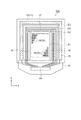
まず、本実施形態の有機EL装置について、図1〜図4を参照して説明する。図1は第
1実施形態の有機EL装置の電気的な構成を示す等価回路図、図2は第1実施形態の有機
EL装置の構成を示す概略平面図、図3はサブ画素の配置を示す概略平面図、図4は図3
のA−A’線に沿ったサブ画素の構造を示す概略断面図である。
(First embodiment)
<Organic EL device>
First, the organic EL device of the present embodiment will be described with reference to FIGS. 1 is an equivalent circuit diagram showing the electrical configuration of the organic EL device of the first embodiment, FIG. 2 is a schematic plan view showing the configuration of the organic EL device of the first embodiment, and FIG. 3 shows the arrangement of sub-pixels. Schematic plan view, FIG. 4 is FIG.
It is a schematic sectional drawing which shows the structure of the sub pixel along line AA '.
図1に示すように、本実施形態の有機EL装置100は、互いに交差する複数の走査線
12及び複数のデータ線13と、複数のデータ線13のそれぞれに対して並列する複数の
電源線14とを有している。複数の走査線12が接続される走査線駆動回路16と、複数
のデータ線13が接続されるデータ線駆動回路15とを有している。また、複数の走査線
12と複数のデータ線13との各交差部に対応してマトリックス状に配置された発光画素
である複数のサブ画素18を有している。
As shown in FIG. 1, the
サブ画素18は、発光素子としての有機EL素子30と、有機EL素子30の駆動を制
御する画素回路20とを有している。
The
有機EL素子30は、陽極としての画素電極31と、陰極としての対向電極33と、画
素電極31と対向電極33との間に設けられた機能層32とを有している。このような有
機EL素子30は電気的にダイオードとして表記することができる。なお、詳しくは後述
するが、対向電極33は複数のサブ画素18に亘る共通陰極として形成されている。
The
画素回路20は、スイッチング用トランジスター21と、蓄積容量22と、駆動用トラ
ンジスター23とを含んでいる。2つのトランジスター21,23は、例えばnチャネル
型もしくはpチャネル型の薄膜トランジスター(TFT;Thin Film Transistor)やM
OSトランジスターを用いて構成することができる。
The
An OS transistor can be used.
スイッチング用トランジスター21のゲートは走査線12に接続され、ソースまたはド
レインのうち一方がデータ線13に接続され、ソースまたはドレインのうち他方が駆動用
トランジスター23のゲートに接続されている。
駆動用トランジスター23のソースまたはドレインのうち一方が有機EL素子30の画
素電極31に接続され、ソースまたはドレインのうち他方が電源線14に接続されている
。駆動用トランジスター23のゲートと電源線14との間に蓄積容量22が接続されてい
る。
The gate of the switching
One of the source and drain of the driving
走査線12が駆動されてスイッチング用トランジスター21がオン状態になると、その
ときにデータ線13から供給される画像信号に基づく電位がスイッチング用トランジスタ
ー21を介して蓄積容量22に保持される。該蓄積容量22の電位すなわち駆動用トラン
ジスター23のゲート電位に応じて、駆動用トランジスター23のオン・オフ状態が決ま
る。そして、駆動用トランジスター23がオン状態になると、電源線14から駆動用トラ
ンジスター23を介して画素電極31と対向電極33とに挟まれた機能層32にゲート電
位に応じた量の電流が流れる。有機EL素子30は、機能層32を流れる電流量に応じて
発光する。
When the
図2に示すように、有機EL装置100は、素子基板10を有している。素子基板10
には、表示領域E0(図中、一点鎖線で表示)と、表示領域E0の外側に非表示領域E3
とが設けられている。表示領域E0は、実表示領域E1(図中、二点鎖線で表示)と、実
表示領域E1を囲むダミー領域E2とを有している。
As shown in FIG. 2, the
Includes a display area E0 (indicated by a one-dot chain line in the figure) and a non-display area E3 outside the display area E0.
And are provided. The display area E0 has an actual display area E1 (indicated by a two-dot chain line in the figure) and a dummy area E2 surrounding the actual display area E1.
実表示領域E1には、発光画素としてのサブ画素18がマトリックス状に配置されてい
る。サブ画素18は、前述したように発光素子としての有機EL素子30を備えており、
スイッチング用トランジスター21及び駆動用トランジスター23の動作に伴って、青(
B)、緑(G)、赤(R)のうちいずれかの色の発光が得られる構成となっている。
In the actual display area E1, sub-pixels 18 as light-emitting pixels are arranged in a matrix. As described above, the
With the operation of the switching
B), light emission of any color among green (G) and red (R) is obtained.
本実施形態では、同色の発光が得られるサブ画素18が第1の方向に配列し、異なる色
の発光が得られるサブ画素18が第1の方向に対して交差(直交)する第2の方向に配列
した、所謂ストライプ方式のサブ画素18の配置となっている。以降、上記第1の方向を
Y方向とし、上記第2の方向をX方向として説明する。なお、素子基板10におけるサブ
画素18の配置はストライプ方式に限定されず、モザイク方式、デルタ方式であってもよ
い。
In the present embodiment, the sub-pixels 18 that can emit light of the same color are arranged in the first direction, and the second direction in which the sub-pixels 18 that can emit light of different colors intersect (orthogonal) the first direction. The so-called stripe-
ダミー領域E2には、主として各サブ画素18の有機EL素子30を発光させるための
周辺回路が設けられている。例えば、図2に示すように、X方向において実表示領域E1
を挟んだ位置にY方向に延在して一対の走査線駆動回路16が設けられている。一対の走
査線駆動回路16の間で実表示領域E1に沿った位置に検査回路17が設けられている。
The dummy area E2 is provided with a peripheral circuit mainly for causing the
A pair of scanning
素子基板10のX方向に平行な一辺部(図中の下方の辺部)に、外部駆動回路との電気
的な接続を図るためのフレキシブル回路基板(FPC)43が接続されている。FPC4
3には、FPC43の配線を介して素子基板10側の周辺回路と接続される駆動用IC4
4が実装されている。駆動用IC44は前述したデータ線駆動回路15を含むものであり
、素子基板10側のデータ線13や電源線14は、フレキシブル回路基板43を介して駆
動用IC44に電気的に接続されている。
A flexible circuit board (FPC) 43 for electrical connection with an external drive circuit is connected to one side (the lower side in the figure) parallel to the X direction of the
3 includes a driving
4 is implemented. The driving
表示領域E0と素子基板10の外縁との間、つまり非表示領域E3には、例えば各サブ
画素18の有機EL素子30の対向電極33に電位を与えるための配線29などが形成さ
れている。配線29は、FPC43が接続される素子基板10の辺部を除いて、表示領域
E0を囲むように素子基板10に設けられている。
Between the display area E0 and the outer edge of the
次に、図3を参照してサブ画素18の平面的な配置、とりわけ画素電極31の平面的な
配置について説明する。図3に示すように、青(B)の発光が得られるサブ画素18B、
緑(G)の発光が得られるサブ画素18G、赤(R)の発光が得られるサブ画素18Rが
X方向に順に配列している。同色の発光が得られるサブ画素18はY方向に隣り合って配
列している。X方向に配列した3つのサブ画素18B,18G,18Rを1つの画素19
として表示がなされる構成になっている。X方向におけるサブ画素18B,18G,18
Rの配置ピッチは5μm未満である。X方向に0.5μm〜1.0μmの間隔を置いてサ
ブ画素18B,18G,18Rが配置されている。Y方向におけるサブ画素18B,18
G,18Rの配置ピッチはおよそ10μm未満である。
Next, the planar arrangement of the sub-pixels 18, particularly the planar arrangement of the
Sub-pixels 18G from which green (G) light emission is obtained and sub-pixels 18R from which red (R) light emission is obtained are arranged in this order in the X direction. The sub-pixels 18 that can emit light of the same color are arranged adjacent to each other in the Y direction. Three sub-pixels 18B, 18G, and 18R arranged in the X direction are combined into one
Is displayed.
The arrangement pitch of R is less than 5 μm.
The arrangement pitch of G and 18R is less than about 10 μm.
サブ画素18における画素電極31は略矩形状であって、長手方向がY方向に沿って配
置されている。画素電極31を発光色に対応させて画素電極31B,31G,31Rと呼
ぶこともある。各画素電極31B,31G,31Rの外縁を覆って絶縁膜27が形成され
ている。これによって、各画素電極31B,31G,31R上に開口部27aが形成され
、開口部27a内において画素電極31B,31G,31Rのそれぞれが露出している。
開口部27aの平面形状もまた略矩形状となっている。
なお、図3では、異なる色のサブ画素18B,18G,18Rの配置は、X方向におい
て左側から青(B)、緑(G)、赤(R)の順になっているが、これに限定されるもので
はない。例えば、X方向において、左側から赤(R)、緑(G)、青(B)の順であって
もよい。
The
The planar shape of the
In FIG. 3, the arrangement of the sub-pixels 18B, 18G, and 18R of different colors is in the order of blue (B), green (G), and red (R) from the left side in the X direction, but is not limited thereto. It is not something. For example, in the X direction, the order may be red (R), green (G), and blue (B) from the left side.
次に、図4を参照してサブ画素18B,18G,18Rの構造について説明する。図4
に示すように、有機EL装置100は、本発明における基板としての基材11と、基材1
1上に順に形成された反射層25、透明層26、画素電極31B,31G,31R、機能
層32、共通陰極である対向電極33を有する。また、対向電極33を覆う封止層34と
、封止層34上に形成されたカラーフィルター36とを有する。さらに、カラーフィルタ
ー36を保護するために、透明樹脂層42を介して配置された対向基板41を有する。素
子基板10は基材11からカラーフィルター36までを含むものである。なお、図4では
、素子基板10における画素回路20の駆動用トランジスター23などの構成について、
図示を省略した。
Next, the structure of the sub-pixels 18B, 18G, and 18R will be described with reference to FIG. FIG.
As shown, the
1 includes a
Illustration is omitted.
有機EL装置100は、機能層32から発した光がカラーフィルター36を透過して対
向基板41側から取り出されるトップエミッション方式が採用されている。したがって、
基材11は透明な例えばガラスなどの基板だけでなく、不透明な例えばシリコンやセラミ
ックスなどの基板を用いることができる。対向基板41は透明な例えばガラスなどの基板
である。
The
As the
基材11上に形成される反射層25は、Al(アルミニウム)やAg(銀)、あるいは
これらの光反射性を有する金属の合金を用いることができる。
The
透明層26は、後に形成される画素電極31と反射層25との電気的な絶縁を図るもの
であって、例えばSiOx(酸化シリコン)などの無機絶縁膜を用いることができる。
The
サブ画素18B,18G,18Rに対応して、透明層26上に設けられた画素電極31
B,31G,31Rは、例えばITO(Indium Tin Oxide)やIZO(Indium Zinc
Oxide)などの透明導電膜からなり、互いに膜厚が異なっている。具体的には、青(B)
、緑(G)、赤(R)の順に膜厚が厚くなっている。
A
B, 31G, and 31R are, for example, ITO (Indium Tin Oxide) and IZO (Indium Zinc).
Oxide) and other transparent conductive films having different film thicknesses. Specifically, blue (B)
, Green (G), red (R) in order of thickness.
機能層32は白色光が得られる有機発光層を含み、サブ画素18B,18G,18Rに
跨って共通に形成されている。なお、白色光は、青(B)、緑(G)、赤(R)の発光が
得られる有機発光層を組み合わせることにより実現できる。また、青(B)と黄(Y)の
発光が得られる有機発光層を組み合わせても擬似白色光を得ることができる。
The
機能層32を覆う対向電極33は、例えばMgAg(マグネシウム銀)合金からなり、
光透過性と光反射性とを兼ね備えるように膜厚が制御されている。
The
The film thickness is controlled to have both light transmittance and light reflectivity.
封止層34は、対向電極33側から第1封止層34a、平坦化層34b、第2封止層3
4cが順に積層された構造となっている。
第1封止層34aと第2封止層34cとは、無機材料を用いて形成されている。無機材
料としては、水分や酸素などを通し難い、例えばSiOx(酸化シリコン)、SiNx(
窒化シリコン)、SiOxNy(酸窒化シリコン)、AlxOy(酸化アルミニウム)な
どが挙げられる。第1封止層34a及び第2封止層34cを形成する方法としては真空蒸
着法、イオンプレーティング法、スパッター法、CVD法などが挙げられる。有機EL素
子30に熱などのダメージを与え難い点で、真空蒸着法やイオンプレーティング法を採用
することが望ましい。第1封止層34a及び第2封止層34cの膜厚は、成膜時にクラッ
クなどが生じ難く、且つ透明性が得られるように、50nm〜1000nm、好ましくは
200nm〜400nmとなっている。
The
4c is laminated in order.
The
Examples thereof include silicon nitride), SiOxNy (silicon oxynitride), and AlxOy (aluminum oxide). Examples of the method for forming the
平坦化層34bは、透明性を有し、例えば、熱または紫外線硬化型のエポキシ樹脂、ア
クリル樹脂、ウレタン樹脂、シリコーン樹脂のいずれかの樹脂材料を用いて形成すること
ができる。また、塗布型の無機材料(酸化シリコンなど)を用いて形成してもよい。平坦
化層34bは、複数の有機EL素子30を覆った第1封止層34aに積層して形成されて
いる。第1封止層34aの表面は、厚みが異なる画素電極31B,31G,31Rの影響
を受けて凹凸が生ずるので、該凹凸を緩和するため、1μm〜5μmの膜厚で平坦化層3
4bを形成することが好ましい。これによって、封止層34上に形成されるカラーフィル
ター36が該凹凸の影響を受け難くなる。
The
Preferably 4b is formed. As a result, the
平坦化層34bを覆う第2封止層34cは、前述した無機材料を用いて形成されている
。
The
カラーフィルター36は、封止層34の上に、フォトリソグラフィー法で形成された青
(B)、緑(G)、赤(R)の着色層36B,36G,36Rを含んで構成されている。
着色層36B,36G,36Rは、サブ画素18B,18G,18Rに対応して形成され
る。
また、封止層34上において、異なる色のサブ画素18B,18G,18Rの着色層3
6B,36G,36Rの間に光透過性の凸部35が設けられている。封止層34上におけ
る凸部35の高さは、着色層36B,36G,36Rの膜厚よりも低い(小さい)。凸部
35の構成について、詳しくは後述するが、封止層34上において凸部35間に各着色層
36B,36G,36Rが形成されると共に、凸部35は着色層36B,36G,36R
のいずれかにより覆われた状態となっている。
The
The colored layers 36B, 36G, and 36R are formed corresponding to the sub-pixels 18B, 18G, and 18R.
On the
A light-transmitting
It is in the state covered with either.
本実施形態の有機EL装置100は、反射層25と対向電極33との間で光共振器が構
成されている。サブ画素18B,18G,18Rごとの画素電極31B,31G,31R
の膜厚が異なることにより、それぞれの光共振器における光学的な距離が異なっている。
これにより、サブ画素18B,18G,18Rのそれぞれにおいて各色に対応した共振波
長の光が得られる構成となっている。
なお、光共振器における光学的な距離の調整方法は、これに限定されず、例えばサブ画
素18B,18G,18Rごとに、基材11上における透明層26の膜厚や透明層26を
構成する材料を異ならせてもよい。
In the
The optical distances in the respective optical resonators differ due to the different film thicknesses.
As a result, in each of the sub-pixels 18B, 18G, and 18R, light having a resonance wavelength corresponding to each color is obtained.
In addition, the adjustment method of the optical distance in an optical resonator is not limited to this, For example, the film thickness of the
各サブ画素18B,18G,18Rの光共振器から発せられた共振光は、各着色層36
B,36G,36Rを透過して透明な対向基板41側から射出される。カラーフィルター
36が封止層34上に形成されているため、カラーフィルター36が対向基板41側に形
成される場合に比べて、サブ画素18B,18G,18R間での光漏れによる混色が低減
される。このようなサブ画素18B,18G,18Rの構造は、サブ画素18B,18G
,18Rの平面的な大きさが小さくなる、つまり高精細になるほど混色を効果的に低減で
きる。
Resonant light emitted from the optical resonators of the sub-pixels 18B, 18G, and 18R is emitted from the colored layers 36.
The light passes through B, 36G, and 36R and is emitted from the
, 18R becomes smaller, that is, the higher the definition, the more effectively the color mixture can be reduced.
次に、封止層34上における凸部35と着色層36B,36G,36Rとの関係につい
て、図5及び図6を参照して説明する。図5(a)はサブ画素における凸部と着色層の配
置を示す概略平面図、図5(b)は図5(a)のA−A’線に沿ったカラーフィルターの
要部断面図、図5(c)は図5(b)の要部拡大断面図である。図6(a)は変形例の凸
部と着色層の配置を示す概略平面図、図6(b)は図6(a)のA−A’線に沿ったカラ
ーフィルターの要部断面図、図6(c)は図6(a)のC−C’線に沿った要部拡大断面
図である。
Next, the relationship between the
図5(a)及び(b)に示すように、本実施形態の有機EL装置100のカラーフィル
ター36は、Y方向に同色の着色層が延在して配置されている。つまり、青(B)の着色
層36Bは、Y方向に配列する複数のサブ画素18B(画素電極31B)に跨ってストラ
イプ状に配置されている。同様に、緑(G)の着色層36Gは、Y方向に配列する複数の
サブ画素18G(画素電極31G)に跨ってストライプ状に配置されている。赤(R)の
着色層36Rは、Y方向に配列する複数のサブ画素18R(画素電極31R)に跨ってス
トライプ状に配置されている。各着色層36B,36G,36Rの境は、X方向に配列す
る隣り合うサブ画素18の画素電極31の間のほぼ中央に位置している。
As shown in FIGS. 5A and 5B, the
図5(b)に示すように、封止層34側において、異なる色の着色層36B,36G,
36Rの間には、これらの着色層36B,36G,36Rをそれぞれ区分するように、封
止層34上に凸部35が配置されている。したがって、封止層34上において凸部35も
Y方向に延在するようにストライプ状(スジ状)に配置されている。
As shown in FIG. 5B, on the
Between 36R, the
図5(a)のA−A’線に沿って切った凸部35の断面形状は、台形であって、凸部3
5の底面は、図5(a)に示すように、隣り合うサブ画素18の画素電極31間に位置し
ている。
なお、各画素電極31の外縁は、絶縁膜27により被覆され、絶縁膜27に設けられた
開口部27aにおいて画素電極31は機能層32と接している。サブ画素18において開
口部27aが実質的に発光に寄与する領域であるため、凸部35の底面が開口部27a以
外の画素電極31と重なるように凸部35を形成してもよい。
The cross-sectional shape of the
5 is located between the
The outer edge of each
本実施形態において、光透過性の凸部35は、着色材料を含まない感光性樹脂材料を用
いてフォトリソグラフィー法で形成されている。すなわち、凸部35と着色層36B,3
6G,36Rの主材料は同じである。封止層34上における凸部35の幅はおよそ0.5
μm〜1.0μm(好ましくは底面の幅が0.7μm、頭頂部35aの幅が0.5μm)
、高さはおよそ1.1μmである。凸部35の高さは、着色層36B,36G,36Rの
平均膜厚tよりも低く(小さく)、平均膜厚tの1/2以上であることが好ましい。
In this embodiment, the light-transmitting
The main materials of 6G and 36R are the same. The width of the
μm to 1.0 μm (preferably the bottom has a width of 0.7 μm and the top 35a has a width of 0.5 μm)
The height is approximately 1.1 μm. The height of the
図5(c)に示すように、本実施形態の着色層36B,36G,36Rの膜厚は、緑(
G)、青(B)、赤(R)の順に厚くなっている。具体的には、着色層36Gの平均膜厚
tgはおよそ1.6μm、着色層36Bの平均膜厚tbはおよそ1.9μm、着色層36
Rの平均膜厚trはおよそ2.0μmである。これは、各色の視感度と、ホワイトバラン
スとを考慮して設定されたものである。
As shown in FIG. 5C, the
G), blue (B), red (R) in order. Specifically, the
The average film thickness tr of R is approximately 2.0 μm. This is set in consideration of the visibility of each color and the white balance.
着色層36B,36G,36Rの形成方法について、詳しくは後述するが、サブ画素1
8Gでは、X方向において向かい合う凸部35間を埋めると共に、凸部35の頭頂部35
aの少なくとも一部を覆うように着色層36Gが形成されている。着色層36Gに隣り合
う着色層36Bは、凸部35の側壁35bに接すると共に、着色層36Bの一方の縁部は
凸部35の頭頂部35aを覆った着色層36Gの縁部と重なっている。同様に、着色層3
6Gに隣り合う着色層36Rは、凸部35の側壁35bに接すると共に、着色層36Rの
一方の縁部は凸部35の頭頂部35aを覆った着色層36Gの縁部と重なっている。つま
り、平均膜厚tgが最も薄い(小さい)着色層36Gは、封止層34と、凸部35の頭頂
部35a及び側壁35bと、着色層36Bの縁部及び着色層36Rの縁部と接するように
形成されている。
Although a method for forming the
In 8G, while filling up between the
A
The
(凸部の変形例)
凸部35は、図5(a)に示すようにY方向に延在したストライプ状に配置されること
に限定されない。例えば、図6(a)に示すように、各サブ画素18の画素電極31にお
ける開口部27aを囲むように、X方向とY方向とに延在して格子状に配置されていても
よい。したがって、図6(b)に示すように、X方向では、頭頂部35aを覆うようにし
て凸部35間に着色層36B,36G,36Rがそれぞれ充填される。また、図6(c)
に示すように、Y方向において同色のサブ画素18R間に位置する凸部35は、頭頂部3
5aを含めて、サブ画素18Rに対応する着色層36Rによって覆われる。このようにす
れば、前述したストライプ状の凸部35間に形成された着色層36Rに対して、変形例の
着色層36Rの方が凸部35に対する接触面積が増えるので、着色層36Rの密着性が向
上する。他の着色層36B,36Gにおいても同様に密着性が向上する。
(Modified example of convex part)
The
As shown in FIG. 4, the
5a is covered by the
<有機EL装置の製造方法>
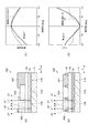
次に、本実施形態の有機EL装置の製造方法について、図7及び図8を参照して説明す
る。図7は第1実施形態の有機EL装置の製造方法を示すフローチャート、図8(a)〜
(f)は第1実施形態の有機EL装置の製造方法を示す概略断面図である。
<Method for manufacturing organic EL device>
Next, a method for manufacturing the organic EL device of this embodiment will be described with reference to FIGS. FIG. 7 is a flowchart showing a method for manufacturing the organic EL device of the first embodiment, and FIG.
(F) is a schematic sectional drawing which shows the manufacturing method of the organic electroluminescent apparatus of 1st Embodiment.
図7に示すように、本実施形態の有機EL装置100の製造方法は、封止層形成工程(
ステップS1)と、凸部形成工程(ステップS2)と、カラーフィルター形成工程(ステ
ップS3)と、基板貼り合わせ工程(ステップS4)とを備えている。なお、基材11上
に画素回路20や有機EL素子30などを形成する方法は、公知の方法を採用することが
できる。したがって、図8(a)〜(f)では、基材11上における画素回路20の駆動
用トランジスター23など構成や反射層25、透明層26の表示を省略している。以降、
本発明の特徴部分である、ステップS1〜ステップS3を重点的に説明する。
As shown in FIG. 7, the manufacturing method of the
Step S1), a convex portion forming step (Step S2), a color filter forming step (Step S3), and a substrate bonding step (Step S4) are provided. As a method for forming the
Steps S1 to S3, which are features of the present invention, will be described mainly.
図7の封止層形成工程(ステップS1)では、図8(a)に示すように、まず、対向電
極33を覆う第1封止層34aを形成する。第1封止層34aを形成する方法としては、
例えばシリコンの酸化物を真空蒸着する方法が挙げられる。第1封止層34aの膜厚はお
よそ200nm〜400nmである。次に、第1封止層34aを覆う平坦化層34bを形
成する。平坦化層34bの形成方法としては、例えば、透明性を有するエポキシ樹脂と、
エポキシ樹脂の溶媒とを含む溶液を用い、印刷法やスピンコート法で該溶液を塗布して乾
燥することにより、エポキシ樹脂からなる平坦化層34bを形成する。平坦化層34bの
膜厚は1μm〜5μmが好ましく、この場合、3μmとした。
なお、平坦化層34bは、エポキシ樹脂などの有機材料を用いて形成することに限定さ
れず、前述したように、塗布型の無機材料を印刷法により塗布し、これを乾燥・焼成する
ことによって、平坦化層34bとして膜厚がおよそ3μmの酸化シリコン膜を形成しても
よい。
続いて、平坦化層34bを覆う第2封止層34cを形成する。第2封止層34cの形成
方法は、第1封止層34aと同じであって、例えばシリコンの酸化物を真空蒸着する方法
が挙げられる。第2封止層34cの膜厚もおよそ200nm〜400nmである。そして
、ステップS2へ進む。
In the sealing layer forming step (step S1) in FIG. 7, first, as shown in FIG. 8A, a
For example, a method of vacuum-depositing silicon oxide can be mentioned. The film thickness of the
A
Note that the
Subsequently, a
図7の凸部形成工程(ステップS2)では、封止層34上に凸部35を形成する。凸部
35の形成方法としては、着色材料を含まない感光性樹脂材料をスピンコート法を用いて
塗布してプレベークすることにより、膜厚がおよそ1μm程度の感光性樹脂層を形成する
。感光性樹脂材料はポジタイプでもネガタイプでもよい。フォトリソグラフィー法を用い
て、感光性樹脂層を露光・現像することにより、図8(b)に示すように、封止層34上
に凸部35を形成する。露光及び現像条件を調整して、底面の幅がおよそ0.7μmとな
るように台形状の凸部35を形成する。基材11上における凸部35の形成位置は、隣り
合う異なる色のサブ画素18B,18G,18Rに対応する画素電極31B,31G,3
1Rの間である。そして、ステップS3へ進む。
In the convex forming process (step S <b> 2) in FIG. 7, the convex 35 is formed on the
Between 1R. Then, the process proceeds to step S3.
図7のカラーフィルター形成工程(ステップS3)では、まず、図8(c)に示すよう
に、凸部35が形成された封止層34の表面に、緑色の着色材料を含む感光性樹脂材料を
スピンコート法により塗布して、感光性樹脂層50gを形成する。感光性樹脂層50gを
露光・現像することにより、図8(d)に示すように、画素電極31Gの上方に位置する
凸部35間を埋めると共に、凸部35の頭頂部を覆うように、ねらいの膜厚が最も薄い(
小さい)着色層36Gを形成する。着色層36Gの平均膜厚はおよそ1.6μmである。
次に、着色層36Gが形成された封止層34の表面に、青色の着色材料を含む感光性樹
脂材料をスピンコート法により塗布して、感光性樹脂層50bを形成する。感光性樹脂層
50bを露光・現像することにより、着色層36Bを形成する。着色層36Bの平均膜厚
はおよそ1.9μmである。
次に、着色層36Bと着色層36Gとが形成された封止層34の表面に、赤色の着色材
料を含む感光性樹脂材料をスピンコート法により塗布して、感光性樹脂層50rを形成す
る。感光性樹脂層50rを露光・現像することにより、着色層36Rを形成する。着色層
36Rの平均膜厚はおよそ2.0μmである。
つまり、カラーフィルター形成工程では、ねらいの膜厚が薄い(小さい)順に、着色層
36G,36B,36Rを形成している。
これにより、図8(e)に示すように、画素電極31Bの上方に位置する凸部35間に
着色層36Bが形成され、画素電極31Gの上方に位置する凸部35間に着色層36Gが
形成され、画素電極31Rの上方に位置する凸部35間に着色層36Rが形成される。
In the color filter forming step (step S3) in FIG. 7, first, as shown in FIG. 8C, a photosensitive resin material containing a green coloring material on the surface of the
The (small)
Next, a photosensitive resin material containing a blue coloring material is applied to the surface of the
Next, a photosensitive resin material containing a red coloring material is applied to the surface of the
That is, in the color filter forming step, the
Thus, as shown in FIG. 8E, a
着色層36GのX方向における縁部の一方(図8(e)では左側)は、凸部35の頭頂
部を覆うと共に、着色層36Bの縁部によって覆われる。着色層36GのX方向における
縁部の他方(図8(e)では右側)は、凸部35の頭頂部を覆うと共に、着色層36Rの
縁部によって覆われる。着色層36BのX方向における縁部の一方(図8(e)では左側
)は、凸部35の頭頂部を覆うと共に、着色層36Rの縁部によって覆われる。着色層3
6BのX方向における縁部の他方(図8(e)では右側)は、着色層36Gの縁部の一方
を覆う。着色層36RのX方向における縁部の一方(図8(e)では左側)は、着色層3
6Gの縁部を覆う。着色層36RのX方向における縁部の他方(図8(e)では右側)は
、着色層36Bの縁部を覆う。そして、ステップS4へ進む。
One of the edges in the X direction of the
The other edge of 6B in the X direction (right side in FIG. 8E) covers one of the edges of the
Cover the 6G edge. The other edge (right side in FIG. 8E) of the
図7の基板貼り合わせ工程(ステップS4)では、図8(f)に示すように、カラーフ
ィルター36を覆うように接着性を有する透明樹脂材料を塗布する。そして、透明樹脂材
料が塗布された基材11に対して対向基板41を所定の位置に対向配置して、例えば対向
基板41を基材11側に押圧する。これにより、透明樹脂材料からなる透明樹脂層42を
介して素子基板10と対向基板41とを貼り合わせる。透明樹脂材料は、例えば熱硬化型
のエポキシ樹脂である。透明樹脂層42の厚みはおよそ10μm〜100μmである。
In the substrate bonding step (step S4) in FIG. 7, an adhesive transparent resin material is applied so as to cover the
この後に、図2に示すように、素子基板10の端子部にFPC43を実装して、有機E
L装置100が完成する。
Thereafter, as shown in FIG. 2, the
The
次に、本実施形態の有機EL装置100における視角特性について、比較例を挙げて説
明する。図9は比較例の有機EL装置と本実施形態の有機EL装置との視角特性を説明す
る図であり、図9(a)は比較例の有機EL装置を示す模式断面図、図9(b)は第1実
施形態の有機EL装置を示す模式断面図、図9(c)は相対輝度に係る視角特性を示すグ
ラフ、図9(d)は色度変化に係る視角特性を示すグラフである。
Next, viewing angle characteristics in the
図9(a)に示すように、比較例の有機EL装置300は、有機EL素子30を備えた
サブ画素の境界において異なる色の着色層が重なった、所謂、重ねCFと呼ばれる構成を
有するものである。図9(b)に示した本実施形態の有機EL装置100との視角特性を
比較するため、着色層36B,36G,36Rの配置と平均膜厚の傾向は、有機EL装置
100と同じとした。比較例の有機EL装置300では、着色層36G(平均膜厚が1.
1μm)、着色層36B(平均膜厚が1.4μm)、着色層36R(平均膜厚が1.5μ
m)の順に平均膜厚が厚くなっている。着色層36Gの平均膜厚が最も薄く(小さく)、
着色層36Gの一方の縁部(図9(a)の左側)は着色層36Bの縁部で覆われ、着色層
36Gの他方の縁部(図9(a)の右側)は着色層36Rの縁部で覆われている。着色層
36Bの一方の縁部(図9(a)の左側)は着色層36Rの縁部で覆われている。
As shown in FIG. 9A, the
1 μm),
The average film thickness increases in the order of m). The average thickness of the
One edge of the
本実施形態の有機EL装置100と比較例の有機EL装置300との視角特性は、青色
のサブ画素における図9(c)に示した相対輝度と、図9(d)に示した色度変化(Δu
’v’)とにおいて、代表して比較されている。基材11上において青色のサブ画素を法
線方向(0°)から見たときを基準として、法線に対してX方向に±20°の範囲で、相
対輝度、色度変化(Δu’v’)を光学シミュレーターを用いて数値化してグラフ化した
。なお、色度変化(Δu’v’)は、均等色度図であるu’v’色度図(CIE 1976 U
CS色度図)における色度変化を示すものである。
青色のサブ画素を比較対象としたのは、有機EL素子30からの発光が本来透過すべき
着色層と異なる色の着色層を透過したときの相対輝度変化や色度変化(Δu’v’)の程
度が、緑色や赤色のサブ画素に比べて顕著となるおそれがあることから選定されたもので
ある。
また、視角特性の範囲を基材11の法線に対してX方向に±20°としたのは、後述す
る電子機器としてのヘッドマウントディスプレイ1000(図12参照)に有機EL装置
100を搭載したときに、求められる条件であることに起因している。本実施形態の有機
EL装置100のようなマイクロディスプレイは、一般的にレンズなどの光学系を介して
使用者が画像(表示光)を視認する。したがって、光学系に飲み込まれる表示光の光学系
の光軸に対する角度範囲が規定されている。
The viewing angle characteristics of the
(v)) as a representative. Relative luminance and chromaticity change (Δu′v) within a range of ± 20 ° in the X direction with respect to the normal, with reference to the blue subpixel viewed from the normal direction (0 °) on the substrate 11 ') Was digitized and graphed using an optical simulator. The chromaticity change (Δu′v ′) is a uniform chromaticity diagram u′v ′ chromaticity diagram (CIE 1976 U
The chromaticity change in the CS chromaticity diagram) is shown.
The blue sub-pixel was used as a comparison target because the relative luminance change or chromaticity change (Δu′v ′) when light emitted from the
The range of the viewing angle characteristic is set to ± 20 ° in the X direction with respect to the normal of the
比較例の有機EL装置300では、X方向に+20°の角度で有機EL素子30から発
した光はサブ画素の境界において、緑の着色層36Gと青の着色層36Bの縁部とを透過
する。X方向に−20°の角度で有機EL素子30から発した光は青の着色層36Bと赤
の着色層36Rの縁部とを透過する。
In the
本実施形態の有機EL装置100では、X方向に+20°の角度で有機EL素子30か
ら発した光は、サブ画素の境界において、凸部35と、凸部35の頭頂部を覆う緑の着色
層36Gと、青の着色層36Bの縁部とを透過する。X方向に−20°の角度で有機EL
素子30から発した光は、サブ画素の境界において、凸部35と、凸部35の頭頂部を覆
う青の着色層36Bと、赤の着色層36Rの縁部とを透過する。
In the
The light emitted from the
図9(c)に示すように、有機EL装置100(透明凸部付きCF)と有機EL装置3
00(重ねCF)とでは、有機EL装置300(重ねCF)のほうがサブ画素の境界にお
いて異なる色の着色層が重なり合った部分を光が透過する割合が有機EL装置100より
も増えることから、視野角を0°±20°に振ったときの相対輝度の変化は、有機EL装
置100(透明凸部付きCF)のほうが小さくなる。また、有機EL装置300では、光
の透過率が緑の着色層36Gよりも低い赤の着色層36Rを透過する割合が−20°側で
増えるため、+20°よりも−20°側の相対輝度が低下し、視角特性上の相対輝度変化
の対称性も有機EL装置100に比べて劣っている。
As shown in FIG. 9C, the organic EL device 100 (CF with a transparent convex portion) and the organic EL device 3
In the case of 00 (overlapping CF), the organic EL device 300 (overlapping CF) is more likely to transmit light through a portion where colored layers of different colors overlap at the subpixel boundary than the
色度変化についても、同じ理由から、図9(d)に示すように、有機EL装置100(
透明凸部付きCF)と有機EL装置300(重ねCF)とでは、視野角が0°±10°の
範囲ではそれほど差が生じないが、視野角を10°から20°へ、あるいは−10°から
−20°へさらに振ったときの色度変化は、有機EL装置300(重ねCF)のほうが有
機EL装置100(透明凸部付きCF)よりも大きくなる。
Regarding the change in chromaticity, for the same reason, as shown in FIG.
Although there is no significant difference between the viewing angle of CF and the organic EL device 300 (overlapping CF) in the range of 0 ° ± 10 °, the viewing angle is changed from 10 ° to 20 ° or −10 °. The chromaticity change when further swung from -20 ° to -20 ° is larger in the organic EL device 300 (overlapping CF) than in the organic EL device 100 (CF with transparent convex portions).
視角特性において相対輝度変化と色度変化とは、視野角が変化しても影響を受け難いこ
とが理想的だが、視野角の変化に対する相対輝度変化及び色度変化における対称性が保た
れていることも重要な要素である。本実施形態の有機EL装置100(透明凸部付きCF
)によれば、比較例の有機EL装置300(重ねCF)に比べて、±20°の視野角範囲
で、相対輝度変化と色度変化とにおける視角特性の対称性が実現されている。
Ideally, the relative luminance change and chromaticity change in the viewing angle characteristics should not be affected even if the viewing angle changes, but the symmetry in the relative luminance change and chromaticity change with respect to the viewing angle change is maintained. This is also an important factor.
), As compared with the organic EL device 300 (overlapping CF) of the comparative example, the symmetry of the viewing angle characteristics in the relative luminance change and the chromaticity change is realized in a viewing angle range of ± 20 °.
上記第1実施形態の有機EL装置100及びその製造方法によれば、以下の効果が得ら
れる。
(1)X方向における異なる色のサブ画素18間に相当する封止層34上に、着色層3
6B,36G,36Rよりも高さが低く、光透過性を有する凸部35が形成されている。
したがって、サブ画素18間において、異なる色の着色層を互いに重ねる場合に比べて、
有機EL素子30から発した光が本来透過すべき着色層に対して異なる色の着色層を透過
する割合が減少するので、相対輝度変化と色度変化とにおける視角特性の対称性が実現さ
れた有機EL装置100を提供及び製造することができる。
(2)凸部35は着色材料を含まない感光性樹脂材料を用いて形成されており、凸部3
5とカラーフィルター36の着色層36B,36G,36Rとは主材料が同じである。ま
た、膜厚が薄い順に着色層36B,36G,36Rが形成され、着色層36B,36Gの
うちいずれか1色の着色層により凸部35の頭頂部35aが覆われ、頭頂部35aを覆っ
た着色層を他の色の着色層の縁部が覆っている。したがって、凸部35に対する着色層3
6B,36G,36Rの密着性が凸部35がない場合に比べて向上する。すなわち、封止
層34に対する着色層36B,36G,36Rの密着性が向上し、着色層36B,36G
,36Rが熱などの環境変化に対して剥がれ難い、高い信頼性を有する有機EL装置10
0を提供及び製造することができる。
(3)着色層36B,36G,36Rは、凸部35が形成された封止層34の表面を覆
うようにスピンコート法で塗布されて形成された着色材料を含む感光性樹脂層を露光・現
像して形成されている。したがって、凸部35が形成されていない場合に比べて、凸部3
5間に感光性樹脂材料が充填されて保持されるので、着色層36B,36G,36Rを厚
膜化し易い。言い換えれば、感光性樹脂材料を効率的に使用して、ねらいの膜厚を有する
着色層36B,36G,36Rを形成することができる。
(4)封止層34上における凸部35のX方向に沿った断面形状は台形であって、封止
層34に接する底面の面積は頭頂部35aの面積よりも大きい。したがって、視角特性に
おける対称性を確保しつつ、封止層34に対する凸部35の密着性を確保できる。
According to the
(1) On the
The
Therefore, compared with the case where the colored layers of different colors are overlapped with each other between the sub-pixels 18,
Since the ratio of the light emitted from the
(2) The
5 and the
The adhesion of 6B, 36G, and 36R is improved as compared with the case where the
, 36R is difficult to peel off due to environmental changes such as heat, and the
0 can be provided and manufactured.
(3) The colored layers 36B, 36G, and 36R are exposed to a photosensitive resin layer that includes a coloring material formed by spin coating so as to cover the surface of the
Since the photosensitive resin material is filled and held between 5, the
(4) The cross-sectional shape along the X direction of the
(第2実施形態)
<他の有機EL装置及びその製造方法>
次に、第2実施形態の有機EL装置について、図10を参照して説明する。図10は第
2実施形態の有機EL装置のサブ画素の構造を示す要部概略断面図である。第2実施形態
の有機EL装置は、第1実施形態の有機EL装置100に対して凸部35の構成を異なら
せたものである。したがって、第1実施形態と同じ構成には同じ符号を付して詳細な説明
は省略する。また、図10は、図4に相当するものであって、図4と同様に基材11上に
おける画素回路20を構成する駆動用トランジスター23などや反射層25、透明層26
の表示を省略している。
(Second Embodiment)
<Other organic EL devices and manufacturing methods thereof>
Next, the organic EL device of the second embodiment will be described with reference to FIG. FIG. 10 is a main part schematic cross-sectional view showing the structure of the sub-pixel of the organic EL device of the second embodiment. The organic EL device of the second embodiment is different from the
Is omitted.
図10に示すように、本実施形態の有機EL装置200は、基材11と、基材11上に
おいてサブ画素18B,18G,18Rごとに形成された複数の有機EL素子30と、複
数の有機EL素子30を覆って封止する封止層34と、封止層34上に形成されたカラー
フィルター36とを備えた素子基板10を有する。素子基板10のカラーフィルター36
側に透明樹脂層42を介して対向配置された対向基板41を有する。有機EL装置200
は、各有機EL素子30からの発光が、カラーフィルター36の着色層36B,36G,
36Rを透過して対向基板41から取り出されるトップエミッション型である。なお、サ
ブ画素18B,18G,18Rの配置は、これに限定されず、例えば、図10において左
側からサブ画素18R、サブ画素18G、サブ画素18Bの順であってもよい。
As shown in FIG. 10, the
A
The light emission from each
This is a top emission type that passes through 36R and is taken out from the
有機EL素子30は、陽極としての画素電極31と、陰極としての対向電極33と、画
素電極31と対向電極33との間に形成された白色発光が得られる機能層32とを有する
。画素電極31はサブ画素18B,18G,18Rごとに独立して設けられ、サブ画素1
8の色に対応させて画素電極31B,31G,31Rと呼ぶこともある。対向電極33は
、複数の有機EL素子30に共通する共通陰極として形成されている。機能層32もまた
、各画素電極31B,31G,31Rに跨って共通に形成されている。
The
The pixel electrodes may be called
基材11上において複数の有機EL素子30を覆う封止層34は、対向電極33側から
第1封止層34a、平坦化層34b、第2封止層34cが順に積層されたものである。
The
サブ画素18間に相当する封止層34上に凸部37が形成されている。上記第1実施形
態の有機EL装置100では、凸部35は光透過性を有していたが、本実施形態の凸部3
7は遮光性を有している。具体的には、凸部37はAl(アルミニウム)などの金属材料
を用いて形成されている。封止層34上における平面的な凸部37の配置は、上記第1実
施形態の凸部35と同じようにY方向に延在するストライプ状であってもよいが、図6(
a)に示したように、サブ画素18B,18G,18Rを区画するように格子状に配置さ
れることが好ましい。すなわち、凸部37はBM(ブラックマトリックス)と呼ばれるも
のに相当する。しかしながら、一般的なBMと違って、単にサブ画素18を囲んで遮光す
るだけでなく、凸部37は、封止層34上において着色層36B,36G,36Rの平均
膜厚よりも低く(小さく)、該平均膜厚の1/2以上の高さを有するものである。また、
X方向における凸部37の断面形状は台形である。以降、凸部37をBM37と呼ぶ。
7 has a light shielding property. Specifically, the
As shown in a), it is preferable that the sub-pixels 18B, 18G, and 18R are arranged in a grid pattern so as to partition. That is, the
The cross-sectional shape of the
有機EL装置200の製造方法は、上記第1実施形態の有機EL装置100の製造方法
における凸部形成工程(ステップS2)において、例えば、封止層34の表面にAl膜を
膜厚がおよそ1μm程度となるように成膜し、フォトリソグラフィー法によりパターニン
グして格子状のBM(凸部)37を形成する。断面形状が台形となるようにBM(凸部)
37を形成する。BM(凸部)37の底面のX方向における幅は、0.5μm〜1.0μ
m、好ましくは0.7μmである。ステップS2以外の工程は、第1実施形態と同じであ
る。
The manufacturing method of the
37 is formed. The width of the bottom surface of the BM (convex portion) 37 in the X direction is 0.5 μm to 1.0 μm.
m, preferably 0.7 μm. Steps other than step S2 are the same as those in the first embodiment.
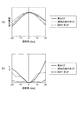
図11は、重ねCFと、透明凸部付きCFと、BM付きCFとの視角特性を示す、(a
)が相対輝度の視角特性のグラフ、(b)が色度変化の視角特性を示すグラフである。
なお、図11(a)及び(b)は、先に示した図9(c)及び(d)のグラフに有機E
L装置200(BM付きCF)のグラフを加えたものである。
図11(a)に示すように、BM付きCFを含む本実施形態の有機EL装置200は、
第1実施形態の有機EL装置100(透明凸部付きCF)よりも、光の利用効率の観点で
劣るので、視野角の変化に対する相対輝度の変化が大きい。その一方で±20°の視野角
範囲では、相対輝度変化の対称性は、比較例の有機EL装置300(重ねCF)よりも優
れている。
FIG. 11 shows viewing angle characteristics of an overlapped CF, a CF with a transparent convex portion, and a CF with a BM.
) Is a graph of viewing angle characteristics of relative luminance, and (b) is a graph showing viewing angle characteristics of chromaticity change.
11 (a) and 11 (b) show organic E in the graphs shown in FIGS. 9 (c) and 9 (d).
The graph of L apparatus 200 (CF with BM) is added.
As shown in FIG. 11A, the
Since it is inferior in terms of light utilization efficiency compared to the organic EL device 100 (CF with transparent convex portion) of the first embodiment, the change in relative luminance with respect to the change in viewing angle is large. On the other hand, in the viewing angle range of ± 20 °, the symmetry of the relative luminance change is superior to that of the organic EL device 300 (overlapping CF) of the comparative example.
また、図11(b)に示すように、本実施形態の有機EL装置200(BM付きCF)
は、BM37を備えることによって、有機EL装置100(透明凸部付きCF)や比較例
の有機EL装置300(重ねCF)よりも色度変化(Δu’v’)が小さい、すなわち色
度変化(Δu’v’)の視角依存性が改善されている。
Further, as shown in FIG. 11B, the organic EL device 200 (CF with BM) of the present embodiment.
Is provided with a
本実施形態の有機EL装置200(BM付きCF)によれば、優れた対称性を有する視
角特性を実現することができる。言い換えれば、視角範囲における色度変化を極力抑えた
い場合には、有機EL装置200が有効である。その一方で、視角範囲における色度変化
の対称性と、相対輝度変化の抑制とが要求される場合には、第1実施形態の有機EL装置
100のほうが有効である。
According to the organic EL device 200 (CF with BM) of the present embodiment, viewing angle characteristics having excellent symmetry can be realized. In other words, the
また、封止層34上に透明凸部付きCFやBM付きCFを形成して、視角特性上の優れ
た対称性を実現する構成は、サブ画素18が高精細になるほど有効である。したがって、
本発明が適用された有機EL装置100及び有機EL装置200は、X方向における配置
ピッチがおよそ5μm未満の高精細なサブ画素18を備えたマイクロディスプレイである
。
In addition, the configuration in which the CF with transparent convex portions and the CF with BM are formed on the
The
(第3実施形態)
<電子機器>
次に、本実施形態の電子機器について、図12を参照して説明する。図12は、電子機
器としてのヘッドマウントディスプレイを示す概略図である。
図12に示すように、本実施形態の電子機器としてのヘッドマウントディスプレイ(H
MD)1000は、左右の目に対応して設けられた2つの表示部1001を有している。
観察者Mはヘッドマウントディスプレイ1000を眼鏡のように頭部に装着することによ
り、表示部1001に表示された文字や画像などを見ることができる。例えば、左右の表
示部1001に視差を考慮した画像を表示すれば、立体的な映像を見て楽しむこともでき
る。
(Third embodiment)
<Electronic equipment>
Next, the electronic apparatus of this embodiment will be described with reference to FIG. FIG. 12 is a schematic diagram showing a head mounted display as an electronic apparatus.
As shown in FIG. 12, the head mounted display (H
MD) 1000 has two
The observer M can see characters and images displayed on the
表示部1001には、上記第1実施形態の有機EL装置100(あるいは上記第2実施
形態の有機EL装置200)が搭載されている。したがって、優れた表示品質を有すると
共に、コストパフォーマンスに優れ小型で軽量なヘッドマウントディスプレイ1000を
提供することができる。
The
ヘッドマウントディスプレイ1000は、2つの表示部1001を有することに限定さ
れず、左右のいずれかに対応させた1つの表示部1001を備える構成としてもよい。
The head mounted
なお、上記有機EL装置100または上記有機EL装置200が搭載される電子機器は
、ヘッドマウントディスプレイ1000に限定されない。例えば、パーソナルコンピュー
ターや携帯型情報端末、ナビゲーター、ビューワー、ヘッドアップディスプレイなどの表
示部を有する電子機器が挙げられる。
The electronic device on which the
本発明は、上記した実施形態に限られるものではなく、請求の範囲及び明細書全体から
読み取れる発明の要旨あるいは思想に反しない範囲で適宜変更可能であり、そのような変
更を伴う有機EL装置及び該有機EL装置の製造方法ならびに該有機EL装置を適用する
電子機器もまた本発明の技術的範囲に含まれるものである。上記実施形態以外にも様々な
変形例が考えられる。以下、変形例を挙げて説明する。
The present invention is not limited to the above-described embodiment, and can be appropriately changed without departing from the spirit or concept of the invention that can be read from the claims and the entire specification. The manufacturing method of the organic EL device and the electronic equipment to which the organic EL device is applied are also included in the technical scope of the present invention. Various modifications other than the above embodiment are conceivable. Hereinafter, a modification will be described.
(変形例1)上記第1実施形態において、凸部35の頭頂部35aを覆う着色層の構成
は、これに限定されない。凸部35が光透過性を有する場合、有機EL素子30の発光が
凸部35を透過して、そのまま対向基板41側から射出されると、カラー表示において光
漏れが生じてコントラストの低下に結びついてしまう。したがって、凸部35の高さは着
色層36B,36G,36Rの平均膜厚よりも低く(小さく)なることが望ましく、且つ
頭頂部35aは着色層36B,36G,36Rで覆われることが好ましい。よって、着色
層36B,36G,36Rのいずれかで覆われることに限定されず、例えば、異なる2色
の着色層が互いに凸部35の頭頂部35aと接する構成であってもよい。
(Modification 1) In the said 1st Embodiment, the structure of the colored layer which covers the
(変形例2)上記第1実施形態において、光透過性を有する凸部35は、感光性樹脂材
料で形成されることに限定されない。例えば、CrOx(酸化クロム)、SiOxNy(
酸化窒化シリコン)、AlOx(酸化アルミニウム)、TaOx(酸化タンタル)、Ti
Ox(酸化チタン)などの誘電体材料を用いて凸部35を形成すれば、封止層34の最上
層である無機材料からなる第2封止層34cに対して高い密着性を有する凸部35を形成
することができる。
(Modification 2) In the first embodiment, the
Silicon oxynitride), AlOx (aluminum oxide), TaOx (tantalum oxide), Ti
If the
(変形例3)上記第1実施形態の凸部35のX方向に沿った断面形状は、台形であるこ
とに限定されない。例えば、断面形状が基材11の法線方向に長い矩形状であってもよい
。法線に対してX方向に±20°の視野角において、有機EL素子30から発せられた光
が矩形状の凸部35を透過したとしても、凸部35は着色層によって覆われているので、
視角特性における対称性を確保することができる。光透過性を有する矩形状の凸部35の
形成方法としては、上記変形例2で挙げた誘電体材料を用いて形成された誘電体層を、例
えばドライエッチングによって異方性エッチングして矩形状の凸部35を形成する方法が
挙げられる。
(Modification 3) The cross-sectional shape along the X direction of the
Symmetry in viewing angle characteristics can be ensured. As a method for forming the light-transmitting
(変形例4)上記第1実施形態の有機EL装置100及び上記第2実施形態の有機EL
装置200において、実表示領域E1に設けられる発光画素は、青(B)、緑(G)、赤
(R)の発光に対応したサブ画素18B,18G,18Rに限定されない。例えば、上記
3色以外の黄(Y)の発光が得られるサブ画素18Yを備えてもよい。これにより、色再
現性をさらに高めることが可能となる。
(Modification 4) The
In the
10…素子基板、11…基板としての基材、18,18B,18G,18R…サブ画素
、30…有機EL素子、31,31B,31G,31R…画素電極、32…機能層、33
…対向電極、34…封止層、34a…第1封止層、34b…平坦化層、34c…第2封止
層、35…凸部、35a…凸部の頭頂部、36…カラーフィルター、36B,36G,3
6R…着色層、37…凸部またはBM、100,200…有機EL装置、1000…電子
機器としてのヘッドマウントディスプレイ。
DESCRIPTION OF
... counter electrode, 34 ... sealing layer, 34a ... first sealing layer, 34b ... flattening layer, 34c ... second sealing layer, 35 ... convex part, 35a ... top part of convex part, 36 ... color filter, 36B, 36G, 3
6R ... colored layer, 37 ... convex portion or BM, 100, 200 ... organic EL device, 1000 ... head mounted display as an electronic device.
Claims (11)
前記基板上に配置された複数の有機EL素子と、
前記複数の有機EL素子を覆って形成された封止層と、
前記封止層上に形成された少なくとも2色の着色層と、
前記2色の着色層間において前記封止層上に設けられた凸部と、を備え、
前記凸部は光透過性を有する材料からなり、
前記凸部の前記封止層側を底面とし、前記凸部の前記封止層とは反対側を頭頂部としたとき、
前記頭頂部は、前記2色の着色層のうち少なくとも一方によって覆われていることを特徴とする有機EL装置。 A substrate,
A plurality of organic EL elements disposed on the substrate;
A sealing layer formed to cover the plurality of organic EL elements;
A colored layer of at least two colors formed on the sealing layer;
A convex portion provided on the sealing layer between the two colored layers,
The convex portion is Ri Do of a material having optical transparency,
When the sealing layer side of the convex portion is the bottom surface, and the side opposite to the sealing layer of the convex portion is the top portion,
The top of the head is covered with at least one of the colored layers of the two colors .
前記凸部は前記サブ画素を区画するように形成されていることを特徴とする請求項1乃至4のいずれか一項に記載の有機EL装置。 The organic EL element and the colored layer are provided for each sub-pixel,
The organic EL device according to any one of claims 1 to 4 wherein the convex portion is characterized in that it is formed so as to partition the sub-pixels.
前記基板上に配置された複数の有機EL素子と、
前記複数の有機EL素子を覆って封止する封止層と、
前記複数の有機EL素子に対応して、前記封止層上に形成された少なくとも赤、緑、青の着色層と、
前記封止層上において異なる色の前記着色層をそれぞれ区分して形成され、前記封止層上における高さが前記着色層よりも低い凸部と、を備え、
前記凸部は光透過性を有する材料からなり、
前記凸部の前記封止層側を底面とし、前記凸部の前記封止層とは反対側を頭頂部としたとき、
前記頭頂部は、少なくとも1色の前記着色層によって覆われていることを特徴とする有機EL装置。 A substrate,
A plurality of organic EL elements disposed on the substrate;
A sealing layer that covers and seals the plurality of organic EL elements;
Corresponding to the plurality of organic EL elements, at least red, green and blue colored layers formed on the sealing layer;
Formed by dividing the colored layers of different colors on the sealing layer, the height on the sealing layer being lower than the colored layer, and
The convex portion is Ri Do of a material having optical transparency,
When the sealing layer side of the convex portion is the bottom surface, and the side opposite to the sealing layer of the convex portion is the top portion,
The top of the head is covered with the colored layer of at least one color .
Priority Applications (12)
| Application Number | Priority Date | Filing Date | Title |
|---|---|---|---|
| JP2012237564A JP6186698B2 (en) | 2012-10-29 | 2012-10-29 | Organic EL devices, electronic devices |
| US14/044,371 US9111881B2 (en) | 2012-10-29 | 2013-10-02 | Organic EL device having a convex portion, method of manufacturing and electronic apparatus having an organic EL device having a convex portion |
| TW106122291A TWI630718B (en) | 2012-10-29 | 2013-10-25 | Organic el device and electronic apparatus |
| TW106122142A TWI630717B (en) | 2012-10-29 | 2013-10-25 | Organic el device and electronic apparatus |
| TW102138764A TWI596760B (en) | 2012-10-29 | 2013-10-25 | Organic el device, method of manufacturing organic el device, and electronic apparatus having the organic el device |
| CN201310516522.2A CN103794735B (en) | 2012-10-29 | 2013-10-28 | Organic el device, the manufacture method of organic el device, electronic equipment |
| CN201810325832.9A CN108321184B (en) | 2012-10-29 | 2013-10-28 | Organic EL device, method for manufacturing organic EL device, and electronic apparatus |
| CN201810325307.7A CN108539042B (en) | 2012-10-29 | 2013-10-28 | Organic EL device, method for manufacturing organic EL device, and electronic apparatus |
| US14/795,575 US9661693B2 (en) | 2012-10-29 | 2015-07-09 | Organic EL device having a convex portion, method of manufacturing organic EL device having a convex portion, and electronic apparatus having an organic EL device having a convex portion |
| US15/200,739 US9661694B2 (en) | 2012-10-29 | 2016-07-01 | Organic EL device having a convex portion, method of manufacturing organic EL device having a convex portion, and electronic apparatus having an organic EL device having a convex portion |
| US15/491,277 US10098192B2 (en) | 2012-10-29 | 2017-04-19 | Organic EL device having a convex portion, method of manufacturing organic EL device having a convex portion, and electronic apparatus having an organic EL device having a convex portion |
| US16/053,246 US11026301B2 (en) | 2012-10-29 | 2018-08-02 | Organic EL device, method of manufacturing organic EL device, and electronic apparatus |
Applications Claiming Priority (1)
| Application Number | Priority Date | Filing Date | Title |
|---|---|---|---|
| JP2012237564A JP6186698B2 (en) | 2012-10-29 | 2012-10-29 | Organic EL devices, electronic devices |
Related Child Applications (1)
| Application Number | Title | Priority Date | Filing Date |
|---|---|---|---|
| JP2017146218A Division JP6443510B2 (en) | 2017-07-28 | 2017-07-28 | Organic EL device, method for manufacturing organic EL device, electronic device |
Publications (3)
| Publication Number | Publication Date |
|---|---|
| JP2014089804A JP2014089804A (en) | 2014-05-15 |
| JP2014089804A5 JP2014089804A5 (en) | 2015-11-19 |
| JP6186698B2 true JP6186698B2 (en) | 2017-08-30 |
Family
ID=50546402
Family Applications (1)
| Application Number | Title | Priority Date | Filing Date |
|---|---|---|---|
| JP2012237564A Active JP6186698B2 (en) | 2012-10-29 | 2012-10-29 | Organic EL devices, electronic devices |
Country Status (4)
| Country | Link |
|---|---|
| US (5) | US9111881B2 (en) |
| JP (1) | JP6186698B2 (en) |
| CN (3) | CN108321184B (en) |
| TW (3) | TWI630717B (en) |
Families Citing this family (49)
| Publication number | Priority date | Publication date | Assignee | Title |
|---|---|---|---|---|
| JP6186698B2 (en) * | 2012-10-29 | 2017-08-30 | セイコーエプソン株式会社 | Organic EL devices, electronic devices |
| JP6318676B2 (en) | 2014-02-14 | 2018-05-09 | セイコーエプソン株式会社 | Organic light emitting device manufacturing method, organic light emitting device, and electronic apparatus |
| WO2015190096A1 (en) * | 2014-06-12 | 2015-12-17 | 株式会社Joled | Organic el display panel |
| US10886337B2 (en) * | 2014-08-20 | 2021-01-05 | Sony Corporation | Display device and electronic apparatus |
| KR20160079975A (en) * | 2014-12-26 | 2016-07-07 | 삼성디스플레이 주식회사 | Organec light emitting display device and method of manufacturing the same |
| US9698389B2 (en) | 2015-03-05 | 2017-07-04 | Seiko Epson Corporation | Method of producing organic EL device |
| JP6550967B2 (en) | 2015-06-30 | 2019-07-31 | セイコーエプソン株式会社 | ORGANIC EL DEVICE, METHOD FOR MANUFACTURING ORGANIC EL DEVICE, AND ELECTRONIC DEVICE |
| KR102368081B1 (en) * | 2015-09-18 | 2022-02-25 | 삼성디스플레이 주식회사 | Manufacturing method for organic light emitting display and organic light emitting diode display using the same |
| JP6696143B2 (en) | 2015-10-07 | 2020-05-20 | セイコーエプソン株式会社 | Organic EL device, method of manufacturing organic EL device, and electronic device |
| KR102516054B1 (en) | 2015-11-13 | 2023-03-31 | 삼성디스플레이 주식회사 | Organic light emitting display apparatus and method for manufacturing the same |
| JP6412036B2 (en) * | 2015-12-21 | 2018-10-24 | 株式会社ジャパンディスプレイ | Display device |
| JP6686497B2 (en) | 2016-02-12 | 2020-04-22 | セイコーエプソン株式会社 | Electro-optical device and electronic equipment |
| JP6299783B2 (en) * | 2016-02-15 | 2018-03-28 | セイコーエプソン株式会社 | Electro-optical device and electronic apparatus |
| JP2017147059A (en) * | 2016-02-15 | 2017-08-24 | セイコーエプソン株式会社 | Electro-optic device and electronic device |
| JP2017182892A (en) * | 2016-03-28 | 2017-10-05 | セイコーエプソン株式会社 | Light-emitting element, light-emitting device and electronic apparatus |
| CN109644531B (en) * | 2016-09-28 | 2021-02-12 | 夏普株式会社 | Organic EL display device and method for manufacturing the same |
| JP6299845B1 (en) | 2016-11-15 | 2018-03-28 | セイコーエプソン株式会社 | Electro-optical device, method of manufacturing electro-optical device, and electronic apparatus |
| JP2018081799A (en) * | 2016-11-15 | 2018-05-24 | セイコーエプソン株式会社 | Electro-optical device, method of manufacturing electro-optical device, and electronic apparatus |
| JP6930092B2 (en) * | 2016-11-17 | 2021-09-01 | セイコーエプソン株式会社 | Electro-optic equipment, manufacturing method of electro-optical equipment, and electronic devices |
| US10312228B2 (en) * | 2017-01-25 | 2019-06-04 | Innolux Corporation | Display device |
| JP6885134B2 (en) | 2017-03-24 | 2021-06-09 | セイコーエプソン株式会社 | Electro-optic equipment, manufacturing method of electro-optic equipment, electronic equipment |
| JP6938323B2 (en) * | 2017-10-13 | 2021-09-22 | 株式会社ジャパンディスプレイ | Display device |
| KR102510569B1 (en) * | 2017-10-27 | 2023-03-15 | 엘지디스플레이 주식회사 | Organic light emitting display device |
| KR102454568B1 (en) * | 2017-12-14 | 2022-10-13 | 엘지디스플레이 주식회사 | Electroluminescent Display Device |
| US11088348B2 (en) | 2018-01-31 | 2021-08-10 | Sakai Display Products Corporation | Method for producing organic electroluminescent display device comprising polydiacetylene layer |
| JP6441547B1 (en) | 2018-01-31 | 2018-12-19 | 堺ディスプレイプロダクト株式会社 | Manufacturing method of organic EL display device |
| JP6551559B2 (en) * | 2018-02-28 | 2019-07-31 | セイコーエプソン株式会社 | Electro-optical device and electronic apparatus |
| JP6642604B2 (en) | 2018-03-01 | 2020-02-05 | セイコーエプソン株式会社 | Electro-optical device, method of manufacturing electro-optical device, and electronic equipment |
| CN114566533A (en) | 2018-05-09 | 2022-05-31 | 京东方科技集团股份有限公司 | Display panel, manufacturing method thereof and display device |
| JPWO2019230328A1 (en) * | 2018-05-31 | 2021-07-26 | コニカミノルタ株式会社 | Display device and manufacturing method of display device |
| CN209771595U (en) * | 2018-06-05 | 2019-12-13 | 咏铨洁能科技有限公司 | Filter material cartridge and filter material box for carrying filter material cartridge |
| JP6746635B2 (en) * | 2018-06-29 | 2020-08-26 | パイオニア株式会社 | Light emitting device |
| CN110783380B (en) * | 2018-07-31 | 2024-01-09 | 乐金显示有限公司 | Display device |
| KR20200055846A (en) * | 2018-11-13 | 2020-05-22 | 삼성디스플레이 주식회사 | Display device |
| JP6726259B2 (en) * | 2018-11-21 | 2020-07-22 | 堺ディスプレイプロダクト株式会社 | Organic EL display device |
| JP6726261B2 (en) * | 2018-11-22 | 2020-07-22 | 堺ディスプレイプロダクト株式会社 | Organic EL display device |
| KR20210113181A (en) | 2019-01-08 | 2021-09-15 | 소니 세미컨덕터 솔루션즈 가부시키가이샤 | display device |
| CN110071069B (en) * | 2019-04-19 | 2021-11-23 | 深圳市华星光电半导体显示技术有限公司 | Display back plate and manufacturing method thereof |
| USD982375S1 (en) | 2019-06-06 | 2023-04-04 | Sharkninja Operating Llc | Food preparation device |
| CN110350111A (en) * | 2019-07-12 | 2019-10-18 | 昆山梦显电子科技有限公司 | The preparation method and display module of high-resolution Micro-OLED |
| US11722729B2 (en) | 2019-07-19 | 2023-08-08 | Roku, Inc. | Method and system for use of earlier and/or later single-match as basis to disambiguate channel multi-match with non-matching programs |
| CN110444687A (en) * | 2019-08-14 | 2019-11-12 | 昆山国显光电有限公司 | Display panel and preparation method thereof |
| KR20210031085A (en) | 2019-09-11 | 2021-03-19 | 삼성전자주식회사 | Light emitting device and methods of manufacturing light emitting device |
| CN110610978A (en) * | 2019-09-29 | 2019-12-24 | 京东方科技集团股份有限公司 | Display substrate, preparation method thereof and display device |
| CN112993131B (en) * | 2019-12-17 | 2023-03-31 | 群创光电股份有限公司 | Method for manufacturing display device |
| JP2021157159A (en) * | 2020-03-30 | 2021-10-07 | 株式会社ジャパンディスプレイ | Display device |
| JP7198250B2 (en) * | 2020-10-12 | 2022-12-28 | キヤノン株式会社 | Display device |
| KR20220064014A (en) * | 2020-11-11 | 2022-05-18 | 엘지디스플레이 주식회사 | Display apparatus having a light-emitting device and a touch electrode |
| CN112864216A (en) * | 2021-04-02 | 2021-05-28 | 维沃移动通信有限公司 | Display panel and electronic device |
Family Cites Families (58)
| Publication number | Priority date | Publication date | Assignee | Title |
|---|---|---|---|---|
| JPH0812288B2 (en) * | 1986-02-25 | 1996-02-07 | 共同印刷株式会社 | Method for manufacturing color filter |
| JP3234691B2 (en) * | 1993-10-21 | 2001-12-04 | 富士写真フイルム株式会社 | Manufacturing method of color filter |
| JP3232866B2 (en) | 1994-04-06 | 2001-11-26 | 株式会社日立製作所 | Method for manufacturing color liquid crystal display device |
| JPH07318713A (en) * | 1994-05-20 | 1995-12-08 | Toppan Printing Co Ltd | Color filter with transparent electrode film |
| JPH08122514A (en) * | 1994-10-20 | 1996-05-17 | Sekisui Chem Co Ltd | Production of pigment dispersed color filter |
| TW542933B (en) * | 1996-12-19 | 2003-07-21 | Sharp Kk | Liquid crystal display device and process for producing the same |
| JP4024009B2 (en) * | 2000-04-21 | 2007-12-19 | Tdk株式会社 | Organic EL device |
| AU2002349405A1 (en) * | 2001-11-22 | 2003-06-10 | Nippon Soda Co., Ltd. | El device |
| JP3501148B2 (en) * | 2002-03-25 | 2004-03-02 | 富士電機ホールディングス株式会社 | Organic EL display |
| US6911772B2 (en) | 2002-06-12 | 2005-06-28 | Eastman Kodak Company | Oled display having color filters for improving contrast |
| JP2004039388A (en) * | 2002-07-02 | 2004-02-05 | Nitto Denko Corp | Optical member, and electroluminescent (el) display type display using the same |
| CN1492265A (en) * | 2002-10-25 | 2004-04-28 | 三星电子株式会社 | Colour filter plate and its producing method and liquid crystal display device including colour filter plate |
| JP4266648B2 (en) * | 2003-01-21 | 2009-05-20 | 三洋電機株式会社 | Electroluminescence display device |
| JP4138672B2 (en) * | 2003-03-27 | 2008-08-27 | セイコーエプソン株式会社 | Manufacturing method of electro-optical device |
| US7728516B2 (en) * | 2003-06-13 | 2010-06-01 | Fuji Electric Holdings Co., Ltd. | Organic EL display |
| US20080036367A1 (en) | 2004-08-26 | 2008-02-14 | Idemitsu Kosan Co., Ltd. | Organic El Display Device |
| JP4592448B2 (en) * | 2005-03-01 | 2010-12-01 | シャープ株式会社 | Substrate for display device |
| JP4641204B2 (en) * | 2005-03-09 | 2011-03-02 | 大日本印刷株式会社 | Color filter and manufacturing method thereof |
| JP4742639B2 (en) * | 2005-03-25 | 2011-08-10 | セイコーエプソン株式会社 | Light emitting device |
| US7960908B2 (en) * | 2005-07-15 | 2011-06-14 | Toshiba Matsushita Display Technology Co., Ltd. | Organic EL display |
| US8102111B2 (en) * | 2005-07-15 | 2012-01-24 | Seiko Epson Corporation | Electroluminescence device, method of manufacturing electroluminescence device, and electronic apparatus |
| US7880382B2 (en) * | 2006-03-08 | 2011-02-01 | Toppan Printing Co., Ltd. | Organic electroluminescence panel and manufacturing method of the same |
| KR20070093261A (en) * | 2006-03-13 | 2007-09-18 | 삼성전자주식회사 | Color filter substrate and display apparatus having the same |
| DE102006027393A1 (en) * | 2006-06-13 | 2007-12-20 | Applied Materials Gmbh & Co. Kg | Encapsulation for organic component |
| KR101299646B1 (en) * | 2006-10-12 | 2013-08-26 | 삼성디스플레이 주식회사 | Display panel and method of manufacturing the same |
| KR101274699B1 (en) * | 2006-12-22 | 2013-06-12 | 엘지디스플레이 주식회사 | The organic light emitting device |
| JP2008165108A (en) | 2007-01-04 | 2008-07-17 | Fuji Electric Holdings Co Ltd | Color filter substrate combinedly having rib function, color conversion filter substrate combinedly having rib function, color organic el element using them and manufacturing method of them |
| JP4479737B2 (en) * | 2007-03-07 | 2010-06-09 | セイコーエプソン株式会社 | LIGHT EMITTING DEVICE, ITS MANUFACTURING METHOD, AND ELECTRONIC DEVICE |
| JP2008225179A (en) * | 2007-03-14 | 2008-09-25 | Sony Corp | Display device, driving method of the display device, and electronic apparatus |
| JP2009020232A (en) * | 2007-07-11 | 2009-01-29 | Hitachi Displays Ltd | Liquid crystal display |
| US20090081356A1 (en) * | 2007-09-26 | 2009-03-26 | Fedorovskaya Elena A | Process for forming thin film encapsulation layers |
| US8063552B2 (en) * | 2007-10-22 | 2011-11-22 | Global Oled Technology Llc | LED device having improved light output |
| JP2009244301A (en) * | 2008-03-28 | 2009-10-22 | Fujifilm Corp | Color filter, manufacturing method therefor, and liquid crystal display |
| JP5515237B2 (en) * | 2008-05-14 | 2014-06-11 | セイコーエプソン株式会社 | LIGHT EMITTING DEVICE AND ELECTRONIC DEVICE |
| CN101971701A (en) * | 2008-07-10 | 2011-02-09 | 富士电机控股株式会社 | Organic el display and method for manufacturing same |
| JP2010027265A (en) * | 2008-07-16 | 2010-02-04 | Seiko Epson Corp | Organic el device and method of manufacturing the same, and electron equipment |
| JP2010056016A (en) * | 2008-08-29 | 2010-03-11 | Fujifilm Corp | Color display device and method of manufacturing the same |
| JP2010096882A (en) * | 2008-10-15 | 2010-04-30 | Sony Corp | Reflection plate, light-emitting device and method for manufacturing reflection plate |
| JP2012047764A (en) | 2008-12-26 | 2012-03-08 | Sharp Corp | Substrate for display device and method of manufacturing the same, and display device |
| JP2010175920A (en) * | 2009-01-30 | 2010-08-12 | Toppan Printing Co Ltd | Method for manufacturing color filter, color filter, and liquid crystal display device |
| JP2010211984A (en) * | 2009-03-09 | 2010-09-24 | Seiko Epson Corp | Organic el device, method for manufacturing the same, and electronic apparatus |
| JP2011071481A (en) * | 2009-08-28 | 2011-04-07 | Fujifilm Corp | Solid-state imaging device, process of making solid-state imaging device, digital still camera, digital video camera, mobile phone, and endoscope |
| KR101058109B1 (en) | 2009-09-15 | 2011-08-24 | 삼성모바일디스플레이주식회사 | Organic light emitting display device |
| EP2490050A1 (en) * | 2009-10-15 | 2012-08-22 | Sharp Kabushiki Kaisha | Color filter substrate and liquid crystal display device |
| JP2011100554A (en) | 2009-11-04 | 2011-05-19 | Panasonic Corp | Light-emitting device |
| JP2011113008A (en) | 2009-11-30 | 2011-06-09 | Toppan Printing Co Ltd | Color filter for liquid crystal display and color liquid crystal display device using the same |
| JP5672695B2 (en) * | 2009-12-18 | 2015-02-18 | セイコーエプソン株式会社 | Display device |
| TWI488540B (en) * | 2010-03-24 | 2015-06-11 | Au Optronics Corp | White organic light-emitting diode |
| WO2011139771A2 (en) * | 2010-04-27 | 2011-11-10 | Orthogonal Inc. | Method for forming a multicolor oled device |
| JP5459142B2 (en) | 2010-08-11 | 2014-04-02 | セイコーエプソン株式会社 | ORGANIC EL DEVICE, METHOD FOR MANUFACTURING ORGANIC EL DEVICE, AND ELECTRONIC DEVICE |
| JP5212447B2 (en) * | 2010-10-28 | 2013-06-19 | 凸版印刷株式会社 | Color filter substrate and fringe field switching type liquid crystal display device using the same |
| US8735874B2 (en) | 2011-02-14 | 2014-05-27 | Semiconductor Energy Laboratory Co., Ltd. | Light-emitting device, display device, and method for manufacturing the same |
| US8884509B2 (en) | 2011-03-02 | 2014-11-11 | Semiconductor Energy Laboratory Co., Ltd. | Optical device, display device, and lighting device |
| US20120226979A1 (en) | 2011-03-04 | 2012-09-06 | Leica Camera Ag | Navigation of a Graphical User Interface Using Multi-Dimensional Menus and Modes |
| JP5605283B2 (en) * | 2011-03-29 | 2014-10-15 | セイコーエプソン株式会社 | Method for manufacturing organic electroluminescence device |
| US9647229B2 (en) * | 2011-10-26 | 2017-05-09 | Dai Nippon Printing Co., Ltd. | Color filter for organic electroluminescence display device, and organic electroluminescence display device |
| JP6186697B2 (en) * | 2012-10-29 | 2017-08-30 | セイコーエプソン株式会社 | Organic EL device manufacturing method, organic EL device, and electronic apparatus |
| JP6186698B2 (en) * | 2012-10-29 | 2017-08-30 | セイコーエプソン株式会社 | Organic EL devices, electronic devices |
-
2012
- 2012-10-29 JP JP2012237564A patent/JP6186698B2/en active Active
-
2013
- 2013-10-02 US US14/044,371 patent/US9111881B2/en active Active
- 2013-10-25 TW TW106122142A patent/TWI630717B/en active
- 2013-10-25 TW TW106122291A patent/TWI630718B/en active
- 2013-10-25 TW TW102138764A patent/TWI596760B/en active
- 2013-10-28 CN CN201810325832.9A patent/CN108321184B/en active Active
- 2013-10-28 CN CN201310516522.2A patent/CN103794735B/en active Active
- 2013-10-28 CN CN201810325307.7A patent/CN108539042B/en active Active
-
2015
- 2015-07-09 US US14/795,575 patent/US9661693B2/en active Active
-
2016
- 2016-07-01 US US15/200,739 patent/US9661694B2/en active Active
-
2017
- 2017-04-19 US US15/491,277 patent/US10098192B2/en active Active
-
2018
- 2018-08-02 US US16/053,246 patent/US11026301B2/en active Active
Also Published As
| Publication number | Publication date |
|---|---|
| CN108321184A (en) | 2018-07-24 |
| TW201735350A (en) | 2017-10-01 |
| TW201735349A (en) | 2017-10-01 |
| CN103794735B (en) | 2018-05-15 |
| US20180343714A1 (en) | 2018-11-29 |
| JP2014089804A (en) | 2014-05-15 |
| US20160316526A1 (en) | 2016-10-27 |
| US9661693B2 (en) | 2017-05-23 |
| TWI596760B (en) | 2017-08-21 |
| US9661694B2 (en) | 2017-05-23 |
| US10098192B2 (en) | 2018-10-09 |
| US20140117842A1 (en) | 2014-05-01 |
| TW201417272A (en) | 2014-05-01 |
| US9111881B2 (en) | 2015-08-18 |
| TWI630717B (en) | 2018-07-21 |
| US11026301B2 (en) | 2021-06-01 |
| CN103794735A (en) | 2014-05-14 |
| US20150327346A1 (en) | 2015-11-12 |
| CN108539042B (en) | 2020-01-21 |
| US20170245330A1 (en) | 2017-08-24 |
| CN108539042A (en) | 2018-09-14 |
| TWI630718B (en) | 2018-07-21 |
| CN108321184B (en) | 2022-01-14 |
Similar Documents
| Publication | Publication Date | Title |
|---|---|---|
| JP6186698B2 (en) | Organic EL devices, electronic devices | |
| JP6318676B2 (en) | Organic light emitting device manufacturing method, organic light emitting device, and electronic apparatus | |
| JP6135062B2 (en) | LIGHT EMITTING DEVICE, LIGHT EMITTING DEVICE MANUFACTURING METHOD, ELECTRONIC DEVICE | |
| CN106328674B (en) | Organic EL device, method for manufacturing organic EL device, and electronic apparatus | |
| JP6187051B2 (en) | Electro-optical device, method of manufacturing electro-optical device, and electronic apparatus | |
| JP6686497B2 (en) | Electro-optical device and electronic equipment | |
| JP6642604B2 (en) | Electro-optical device, method of manufacturing electro-optical device, and electronic equipment | |
| JP2016143606A (en) | Organic el device and electronic apparatus | |
| JP6318478B2 (en) | ORGANIC EL DEVICE, METHOD FOR MANUFACTURING ORGANIC EL DEVICE, AND ELECTRONIC DEVICE | |
| JP6492403B2 (en) | Organic EL device, method for manufacturing organic EL device, electronic device | |
| JP6507545B2 (en) | Organic electroluminescent device, method of manufacturing organic electroluminescent device, electronic device | |
| JP2016143630A (en) | Organic el device and electronic apparatus | |
| JP7010279B2 (en) | Electro-optics, manufacturing methods of electro-optics, electronic devices | |
| JP2015201256A (en) | Method for manufacturing organic electroluminescent device and electronic equipment | |
| JP6627955B2 (en) | Organic EL device and electronic equipment | |
| JP6443510B2 (en) | Organic EL device, method for manufacturing organic EL device, electronic device | |
| JP2017010750A (en) | Organic el device, manufacturing method of the same, and electronic apparatus | |
| JP2015197996A (en) | Method for manufacturing organic electroluminescent device, organic electroluminescent device, and electronic equipment |
Legal Events
| Date | Code | Title | Description |
|---|---|---|---|
| RD04 | Notification of resignation of power of attorney |
Free format text: JAPANESE INTERMEDIATE CODE: A7424 Effective date: 20150108 |
|
| A521 | Request for written amendment filed |
Free format text: JAPANESE INTERMEDIATE CODE: A523 Effective date: 20150930 |
|
| A621 | Written request for application examination |
Free format text: JAPANESE INTERMEDIATE CODE: A621 Effective date: 20150930 |
|
| RD04 | Notification of resignation of power of attorney |
Free format text: JAPANESE INTERMEDIATE CODE: A7424 Effective date: 20160610 |
|
| A977 | Report on retrieval |
Free format text: JAPANESE INTERMEDIATE CODE: A971007 Effective date: 20160615 |
|
| RD03 | Notification of appointment of power of attorney |
Free format text: JAPANESE INTERMEDIATE CODE: A7423 Effective date: 20160624 |
|
| A131 | Notification of reasons for refusal |
Free format text: JAPANESE INTERMEDIATE CODE: A131 Effective date: 20160705 |
|
| A521 | Request for written amendment filed |
Free format text: JAPANESE INTERMEDIATE CODE: A523 Effective date: 20160831 |
|
| A131 | Notification of reasons for refusal |
Free format text: JAPANESE INTERMEDIATE CODE: A131 Effective date: 20170207 |
|
| A521 | Request for written amendment filed |
Free format text: JAPANESE INTERMEDIATE CODE: A523 Effective date: 20170403 |
|
| TRDD | Decision of grant or rejection written | ||
| A01 | Written decision to grant a patent or to grant a registration (utility model) |
Free format text: JAPANESE INTERMEDIATE CODE: A01 Effective date: 20170704 |
|
| A61 | First payment of annual fees (during grant procedure) |
Free format text: JAPANESE INTERMEDIATE CODE: A61 Effective date: 20170717 |
|
| R150 | Certificate of patent or registration of utility model |
Ref document number: 6186698 Country of ref document: JP Free format text: JAPANESE INTERMEDIATE CODE: R150 |