JP6180836B2 - Airbag device - Google Patents

Airbag device Download PDF

Info

Publication number
JP6180836B2
JP6180836B2 JP2013154205A JP2013154205A JP6180836B2 JP 6180836 B2 JP6180836 B2 JP 6180836B2 JP 2013154205 A JP2013154205 A JP 2013154205A JP 2013154205 A JP2013154205 A JP 2013154205A JP 6180836 B2 JP6180836 B2 JP 6180836B2
Authority
JP
Japan
Prior art keywords
horn
mounting plate
airbag
flange
steering wheel
Prior art date
Legal status (The legal status is an assumption and is not a legal conclusion. Google has not performed a legal analysis and makes no representation as to the accuracy of the status listed.)
Active
Application number
JP2013154205A
Other languages
Japanese (ja)
Other versions
JP2015024699A (en
Inventor
龍一郎 辻本
龍一郎 辻本
克典 今井
克典 今井
純一 清原
純一 清原
Current Assignee (The listed assignees may be inaccurate. Google has not performed a legal analysis and makes no representation or warranty as to the accuracy of the list.)
Ashimori Industry Co Ltd
Original Assignee
Ashimori Industry Co Ltd
Priority date (The priority date is an assumption and is not a legal conclusion. Google has not performed a legal analysis and makes no representation as to the accuracy of the date listed.)
Filing date
Publication date
Application filed by Ashimori Industry Co Ltd filed Critical Ashimori Industry Co Ltd
Priority to JP2013154205A priority Critical patent/JP6180836B2/en
Publication of JP2015024699A publication Critical patent/JP2015024699A/en
Application granted granted Critical
Publication of JP6180836B2 publication Critical patent/JP6180836B2/en
Active legal-status Critical Current
Anticipated expiration legal-status Critical

Links

Images

Description

この発明は、エアバッグ装置に関する。   The present invention relates to an airbag device.

特許文献1においては、車両のステアリングホイールに取り付けられるエアバッグ装置について記載されている。このエアバッグ装置は、複数の接点用部材を有している。これらの複数の接点用部材には、それぞれホーンスイッチ用接点が設けられており、また、インフレータを介して互いに電気的に接続されている。そして、運転手によってエアバッグ装置がステアリングホイール側に押し込まれると、ホーンスイッチ用接点がステアリングホイール側の固定接点に接触して、ホーンが鳴る。   Patent Document 1 describes an airbag device attached to a steering wheel of a vehicle. The airbag device has a plurality of contact members. Each of the plurality of contact members is provided with a horn switch contact and is electrically connected to each other via an inflator. When the airbag device is pushed into the steering wheel by the driver, the horn switch contact comes into contact with the stationary contact on the steering wheel, and the horn sounds.

特許文献1では、複数の接点用部材は、インフレータのフランジ部と、リテーナ(取付プレート)とによって挟まれる。これにより、複数の接点用部材をインフレータのフランジ部に強固に接触させている。   In Patent Document 1, a plurality of contact members are sandwiched between a flange portion of an inflator and a retainer (mounting plate). As a result, the plurality of contact members are firmly brought into contact with the flange portion of the inflator.

なお本発明に関連する技術として、特許文献2が開示されている。   Patent Document 2 is disclosed as a technique related to the present invention.

特開2013−95225号公報JP 2013-95225 A 特開2011−121498号公報JP 2011-121498 A

しかしながら、特許文献1では、インフレータのフランジ部とリテーナとの間には、複数の接点用部材の先端部が介在する。しかも、この先端部同士は、互いに離間している。よって、当該先端部の相互間において、フランジ部とリテーナとの間に隙間が生じ得る。これにより、リテーナよりもエアバッグ側の空間と、リテーナよりもステアリングホイール側の空間とが、当該隙間を介して連通する。この場合、インフレータから発生するガスが、当該隙間を介して、ステアリングホイール側へと漏れる。   However, in patent document 1, the front-end | tip part of the some member for contacts interposes between the flange part and retainer of an inflator. In addition, the tips are spaced apart from each other. Therefore, a gap may be generated between the flange portion and the retainer between the tip portions. Thereby, the space on the airbag side from the retainer and the space on the steering wheel side from the retainer communicate with each other through the gap. In this case, gas generated from the inflator leaks to the steering wheel side through the gap.

そこで、本発明は、インフレータからのガスの漏れを抑制できるエアバッグ装置を提供することを目的とする。   Then, an object of this invention is to provide the airbag apparatus which can suppress the leak of the gas from an inflator.

本発明にかかるエアバッグ装置の第1の態様は、ホーン接点を有するステアリングホイールに取付けられるエアバッグ装置であって、エアバッグと、前記エアバッグを膨張展開させるインフレータ本体部と、前記インフレータ本体部の外周に設けられたフランジとを有するインフレータと、前記インフレータ本体部が貫通する開口を有し、前記開口の周縁において前記フランジが対面して固定されるとともに、折り畳まれた前記エアバッグが固定され、外力により前記ステアリングホイールに近づき、前記外力の消失により元の位置に復帰するように、前記ステアリングホイールに取り付けられる取付プレートと、前記取付プレートに固定されており、かつ、前記取付プレートが前記ステアリングホイール側に近づいた押圧状態において、前記ホーン接点と接触する接触部を有し、前記取付プレートが元の位置に復帰した通常状態において、前記ホーン接点と離間するホーン用導体とを備え、前記ホーン用導体は、前記取付プレートと前記フランジとによって挟まれる挟込部分を有し、前記取付プレートと前記フランジとの間に生じる隙間を低減する閉鎖部が、前記開口を取り囲んで設けられ、前記閉鎖部は、前記取付プレートおよび前記フランジの何れか一方に設けられ、前記一方から他方へと突出する突起部である1st aspect of the airbag apparatus concerning this invention is an airbag apparatus attached to the steering wheel which has a horn contact, Comprising: The airbag, the inflator main-body part which inflate-deploys the said airbag, and the said inflator main-body part An inflator having a flange provided on an outer periphery of the inflator, and an opening through which the inflator main body passes, and the flange is fixed to face the periphery of the opening, and the folded airbag is fixed A mounting plate attached to the steering wheel and fixed to the mounting plate so as to approach the steering wheel by an external force and return to the original position by the disappearance of the external force, and the mounting plate is fixed to the steering wheel In the pressed state approaching the wheel side, the front A horn contact having a contact portion that contacts the horn contact, the horn contact being separated from the horn contact in a normal state in which the mounting plate is returned to its original position, the horn conductor including the mounting plate and the flange; And a closing portion for reducing a gap generated between the mounting plate and the flange is provided to surround the opening, and the closing portion is provided between the mounting plate and the flange. It is a projection provided on either side and protruding from the one side to the other side .

本発明にかかるエアバッグ装置の第の態様は、ホーン接点を有するステアリングホイールに取付けられるエアバッグ装置であって、エアバッグと、前記エアバッグを膨張展開させるインフレータ本体部と、前記インフレータ本体部の外周に設けられたフランジとを有するインフレータと、前記インフレータ本体部が貫通する開口を有し、前記開口の周縁において前記フランジが対面して固定されるとともに、折り畳まれた前記エアバッグが固定され、外力により前記ステアリングホイールに近づき、前記外力の消失により元の位置に復帰するように、前記ステアリングホイールに取り付けられる取付プレートと、前記取付プレートに固定されており、かつ、前記取付プレートが前記ステアリングホイール側に近づいた押圧状態において、前記ホーン接点と接触する接触部を有し、前記取付プレートが元の位置に復帰した通常状態において、前記ホーン接点と離間するホーン用導体とを備え、前記ホーン用導体は、前記取付プレートと前記フランジとによって挟まれる挟込部分を有し、前記取付プレートと前記フランジとの間に生じる隙間を低減する閉鎖部が、前記開口を取り囲んで設けられ、前記閉鎖部は、前記取付プレートおよび前記フランジの何れか一方に設けられ、前記一方から他方へと突出する突起部と、前記挟込部分とによって形成される。 A second aspect of the airbag apparatus according to the present invention is an airbag apparatus that is attached to a steering wheel having a horn contact, and includes an airbag, an inflator body that inflates and deploys the airbag, and the inflator body. An inflator having a flange provided on an outer periphery of the inflator, and an opening through which the inflator main body passes, and the flange is fixed to face the periphery of the opening, and the folded airbag is fixed A mounting plate attached to the steering wheel and fixed to the mounting plate so as to approach the steering wheel by an external force and return to the original position by the disappearance of the external force, and the mounting plate is fixed to the steering wheel In the pressed state approaching the wheel side, the front A horn contact having a contact portion that contacts the horn contact, the horn contact being separated from the horn contact in a normal state in which the mounting plate is returned to its original position, the horn conductor including the mounting plate and the flange; has a pinching portion that is sandwiched between the closure part to reduce the gap formed between the mounting plate and said flange is provided surrounding the opening, the front Symbol closure, the mounting plate and the flange either provided on one of a protrusion protruding to the from one to the other, Ru is formed by said nip portion.

本発明にかかるエアバッグ装置の第の態様は、第または第の態様にかかるエアバッグ装置であって、前記突起部の高さは、前記挟込部分の厚みと等しい。 A third aspect of the airbag apparatus according to the present invention is an airbag device according to the first or second aspect, the height of the protrusions, etc arbitrarily the thickness of said nipping portion.

本発明にかかるエアバッグ装置の第の態様は、第1から第のいずれか一つの態様にかかるエアバッグ装置であって、前記閉鎖部は、前記開口の周縁に位置する。 A fourth aspect of the airbag apparatus according to the present invention is the airbag apparatus according to any one of the first to third aspects, wherein the closing portion is located at the periphery of the opening.

本発明にかかるエアバッグ装置の第の態様は、第1から第のいずれか一つの態様にかかるエアバッグ装置であって、折り畳まれた前記エアバッグの開口周縁部、前記フランジ、前記取付プレート、及び、前記ホーン用導体を貫く締結部材によって、前記エアバッグ、前記フランジ、前記取付プレートおよび前記ホーン用導体が締結固定される。 A fifth aspect of the airbag device according to the present invention is the airbag device according to any one of the first to fourth aspects, wherein the opening peripheral edge of the folded airbag, the flange , and the attachment The airbag, the flange , the mounting plate, and the horn conductor are fastened and fixed by a fastening member that penetrates the plate and the horn conductor.

本発明にかかるエアバッグ装置の第1の態様によれば、取付プレートとフランジとの隙間を低減する閉鎖部が開口を取り囲むので、インフレータからのガスが当該隙間を介してエアバッグとは反対側へと漏れ出ることを抑制できる。   According to the first aspect of the airbag apparatus according to the present invention, the closing portion that reduces the gap between the mounting plate and the flange surrounds the opening, so that the gas from the inflator is opposite to the airbag via the gap. It is possible to suppress leakage into

しかも、突起部が開口を取り囲むので、製造が容易である。 In addition, since the protrusion surrounds the opening, manufacturing is easy.

本発明にかかるエアバッグ装置の第の態様によれば、突起部と挟込部分の組み合わせで閉鎖部の形状を決定できるので、設計の自由度が高まり、突起部とホーン用導体の形状を多様化できる。 According to the second aspect of the airbag device according to the present invention, the shape of the closing portion can be determined by the combination of the protruding portion and the sandwiching portion. Can be diversified.

本発明にかかるエアバッグ装置の第の態様によれば、隙間を減らすことができ、ガス漏れを抑制できる。 According to the 3rd aspect of the airbag apparatus concerning this invention, a clearance gap can be reduced and gas leak can be suppressed.

本発明にかかるエアバッグ装置の第の態様によれば、閉鎖部が開口の周縁から遠い位置に形成されると、閉鎖部と取付プレートと取付フランジとで形成される空間が大きくなる。この空間にガスが充填されると、そのガスはエアバッグの膨張展開には寄与しないことになる。第の態様によれば、そのような空間を低減できるので、エアバッグの膨張展開に寄与するガスの量の損失を低減できる。 According to the 4th aspect of the airbag apparatus concerning this invention, if a closure part is formed in the position far from the periphery of opening, the space formed with a closure part, an attachment plate, and an attachment flange will become large. When this space is filled with gas, the gas does not contribute to the inflation and deployment of the airbag. According to the 4th aspect, since such a space can be reduced, the loss of the quantity of the gas which contributes to the expansion | deployment deployment of an airbag can be reduced.

本発明にかかるエアバッグ装置の第の態様によれば、製造コストを上げずに、容易にホーン用導体のがたつきを低減できる。
According to the 5th aspect of the airbag apparatus concerning this invention, the rattling of the conductor for horns can be reduced easily, without raising manufacturing cost.

実施形態に係るステアリングホイールおよびエアバッグ装置の概念的な一例を示す分解斜視図である。It is a disassembled perspective view which shows a conceptual example of the steering wheel and airbag apparatus which concern on embodiment. 同上のステアリングホイールおよびエアバッグ装置の概念的な一例を示す分解斜視図である。It is a disassembled perspective view which shows a conceptual example of a steering wheel and an airbag apparatus same as the above. 取付プレートとホーン用導体とインフレータの取付フランジとの概念的な構成の一例を示す分解斜視図である。It is a disassembled perspective view which shows an example of a notional structure with an attachment plate, the conductor for horns, and the attachment flange of an inflator. 取付プレートとホーン用導体との概念的な構成の一例を示す斜視図である。It is a perspective view which shows an example of a notional structure of a mounting plate and a horn conductor. 取付プレートとホーン用導体とインフレータとの概念的な構成の一例を示す斜視図である。It is a perspective view which shows an example of a notional structure of a mounting plate, the conductor for horns, and an inflator. 取付プレートとインフレータとの概念的な構成の一例を示す断面図である。It is sectional drawing which shows an example of a notional structure of an attachment plate and an inflator. 図7の破線の領域を拡大して示す図である。It is a figure which expands and shows the area | region of the broken line of FIG. 取付プレートとインフレータとの概念的な構成の一例を示す断面図である。It is sectional drawing which shows an example of a notional structure of an attachment plate and an inflator. 取付プレートとホーン用導体とインフレータとの概念的な構成の一例を示す断面図である。It is sectional drawing which shows an example of a notional structure of a mounting plate, the conductor for horns, and an inflator. 取付プレートとホーン用導体との概念的な構成の一例を示す断面図である。It is sectional drawing which shows an example of a notional structure of a mounting plate and the conductor for horns. 取付プレートとインフレータとの概念的な構成の一例を示す断面図である。It is sectional drawing which shows an example of a notional structure of an attachment plate and an inflator. 取付プレートとインフレータとホーン用導体の概念的な構成の一例を示す平面図である。It is a top view which shows an example of a notional structure of a mounting plate, an inflator, and a horn conductor. 取付プレートとホーン用導体との概念的な構成の一例を示す平面図である。It is a top view which shows an example of a notional structure of a mounting plate and a horn conductor. 突起部の近傍の領域の概念的な一例を示す断面図である。It is sectional drawing which shows a conceptual example of the area | region of the vicinity of a projection part.

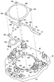
以下、実施形態に係るエアバッグ装置について説明する。図1および図2はステアリングホイール10およびエアバッグ装置30を示す分解斜視図である。   Hereinafter, the airbag apparatus according to the embodiment will be described. 1 and 2 are exploded perspective views showing the steering wheel 10 and the airbag device 30. FIG.

<1.ステアリングホイール10とエアバッグ装置30との全体構成>
このエアバッグ装置30は、車両におけるステアリングホイール10に取付可能に構成されている。以下に、ステアリングホイール10およびエアバッグ装置30の全体構成について概略的に説明する。
<1. Overall Configuration of Steering Wheel 10 and Airbag Device 30>
The airbag device 30 is configured to be attachable to a steering wheel 10 in a vehicle. Below, the whole structure of the steering wheel 10 and the airbag apparatus 30 is demonstrated roughly.

<1−1.ステアリングホイール>
ステアリングホイール10は、車両の操舵を行うためのものであり、ホイール本体12とスポーク14と中央部材16とを備えている。ホイール本体12は、リング状に形成されており、人による操舵力を受ける部分である。中央部材16は、運転手から遠ざかる方向に延出するステアリングシャフトの先端部に連結可能に構成されている。スポーク14は、ホイール本体12の内周部分からその中央に向けて延びており、当該中央において中央部材16に連結されている。ここでは、スポーク14は、3つ設けられているが、2つ等であってもよい。そして、ステアリングホイール10を回転させると、その回転運動がスポーク14および中央部材16を介してステアリングシャフトに伝達されるようになっている。
<1-1. Steering wheel>
The steering wheel 10 is for steering the vehicle, and includes a wheel body 12, spokes 14, and a central member 16. The wheel main body 12 is formed in a ring shape and is a portion that receives a steering force by a person. The central member 16 is configured to be connectable to a distal end portion of a steering shaft that extends in a direction away from the driver. The spoke 14 extends from the inner peripheral portion of the wheel body 12 toward the center thereof, and is connected to the central member 16 at the center. Here, three spokes 14 are provided, but two or the like may be provided. When the steering wheel 10 is rotated, the rotational motion is transmitted to the steering shaft via the spokes 14 and the central member 16.

上記中央部材16には、エアバッグ装置30とステアリングホイール10とを固定するための取付構造が設けられる。例えば中央部材16には、取付突部162と取付凹部164とが設けられる。取付突部162は運転手側に突出している。また取付突部162はその先端側で爪部を有しており、エアバッグ装置30に設けられた係止体60(図2参照)と係止する。再び図1を参照して、取付凹部164は中央部材16に凹設されており、運転手側に開口している。取付凹部164には、エアバッグ装置30と固定される取付挿入部材25が挿入され、取付凹部164と取付挿入部材25とが互いに固定される。係止体60および取付挿入部材25については後にも述べる。   The central member 16 is provided with an attachment structure for fixing the airbag device 30 and the steering wheel 10. For example, the central member 16 is provided with an attachment protrusion 162 and an attachment recess 164. The mounting protrusion 162 protrudes toward the driver. Further, the attachment protrusion 162 has a claw portion at the tip end side, and is engaged with an engagement body 60 (see FIG. 2) provided in the airbag device 30. Referring to FIG. 1 again, the mounting recess 164 is recessed in the central member 16 and opens to the driver side. An attachment insertion member 25 fixed to the airbag device 30 is inserted into the attachment recess 164, and the attachment recess 164 and the attachment insertion member 25 are fixed to each other. The locking body 60 and the attachment insertion member 25 will be described later.

また中央部材16にはホーン接点166が設けられている。このホーン接点166は、いわゆるホーンを鳴らすためのものである。エアバッグ装置30は、運転手側からプッシュ可能にステアリングホイール10に固定されており、運転手がエアバッグ装置30を押し込むことで、ホーン接点166が、エアバッグ装置30に設けられるホーン接点72に当接し、この当接によってホーンが鳴る。   The central member 16 is provided with a horn contact 166. The horn contact 166 is for sounding a so-called horn. The airbag device 30 is fixed to the steering wheel 10 so as to be pushable from the driver side. When the driver pushes the airbag device 30, the horn contact 166 becomes a horn contact 72 provided in the airbag device 30. The horn sounds by this contact.

<1−2.エアバッグ装置>
エアバッグ装置30は、エアバッグ32と、インフレータ34と、カバー36と、取付プレート40と、係止体60と、ホーン用導体70とを備えている。
<1-2. Airbag device>
The airbag device 30 includes an airbag 32, an inflator 34, a cover 36, a mounting plate 40, a locking body 60, and a horn conductor 70.

エアバッグ32は、布等で袋状に形成されており、カバー36内に収容可能なように折畳まれている。   The airbag 32 is formed in a bag shape with cloth or the like, and is folded so as to be accommodated in the cover 36.

インフレータ34は、エアバッグ32を膨張展開させる装置である。ここでは、インフレータ34は、短円柱状のインフレータ本体部34aと、インフレータ本体部34aの外周に形成された取付フランジ34bとを有している。インフレータ本体部34aには、点火装置およびガス発生剤等が組込まれている。そして、車両衝突時に衝撃検知部等からの検知信号等を受けると、当該点火装置がガス発生剤を点火する。これにより、ガス発生剤が燃焼し、この燃焼によって発生するガスがエアバッグ32内に供給される。これにより、エアバッグ32が運転手に向けて膨張展開する。取付フランジ34bは、外周縁が方形状をなすように延出する板状に形成され、その4つの角部分にネジ貫通孔34cが形成されている。   The inflator 34 is a device that inflates and deploys the airbag 32. Here, the inflator 34 has a short cylindrical inflator body 34a and a mounting flange 34b formed on the outer periphery of the inflator body 34a. An ignition device, a gas generating agent, and the like are incorporated in the inflator main body 34a. And when the detection signal etc. from an impact detection part etc. are received at the time of a vehicle collision, the said ignition device will ignite a gas generating agent. As a result, the gas generating agent burns, and the gas generated by this combustion is supplied into the airbag 32. As a result, the airbag 32 is inflated and deployed toward the driver. The mounting flange 34b is formed in a plate shape extending so that the outer peripheral edge forms a square shape, and screw through holes 34c are formed at four corner portions thereof.

カバー36は、樹脂等により形成された部材であり、カバー本体37と立壁38とを有している。カバー本体37は、エアバッグ装置30がステアリングホイール10に取付固定された状態で、操舵装置(エアバッグ付きステアリングホイール)の前面を形成する部分である。このカバー本体37は、折り畳まれたエアバッグ32を一方側(ステアリングホイール10とは反対側)から覆う。立壁38は、カバー本体37の内面側で折畳まれたエアバッグ32の周りを囲うように、カバー本体37に突設されている。ここでは、立壁38は、角筒状に形成されているが、その他、円筒状、或は、エアバッグ32の周りを部分的に囲う形状に形成されていてもよい。そして、折畳まれたエアバッグ32が、カバー本体37および立壁38で囲まれる空間内に収容される。なお、カバー本体37には、エアバッグ32の膨張展開力を受けて破断するティアラインが形成されている。   The cover 36 is a member formed of resin or the like, and includes a cover main body 37 and a standing wall 38. The cover body 37 is a part that forms the front surface of the steering device (the steering wheel with an airbag) in a state where the airbag device 30 is attached and fixed to the steering wheel 10. The cover body 37 covers the folded airbag 32 from one side (the side opposite to the steering wheel 10). The standing wall 38 protrudes from the cover main body 37 so as to surround the airbag 32 folded on the inner surface side of the cover main body 37. Here, the standing wall 38 is formed in a rectangular tube shape, but may be formed in a cylindrical shape or a shape that partially surrounds the airbag 32. The folded airbag 32 is accommodated in a space surrounded by the cover main body 37 and the standing wall 38. The cover body 37 is formed with a tear line that is broken by receiving the inflating and deploying force of the airbag 32.

取付プレート40は、上記インフレータ34が取付けられた状態で、立壁38の開口を塞ぐようにエアバッグ32に取付けられる。   The attachment plate 40 is attached to the airbag 32 so as to close the opening of the standing wall 38 in a state where the inflator 34 is attached.

取付プレート40は、例えば立壁38の外周に沿った形状を有する板状部材に形成されている。ここでは、取付プレート40は、立壁38の開口と同じ形状の周縁を有する板部42と、板部42の外周囲に形成された周壁48とを有している。周壁48は立壁38に外嵌めされる。   The mounting plate 40 is formed as a plate-like member having a shape along the outer periphery of the standing wall 38, for example. Here, the mounting plate 40 has a plate portion 42 having a peripheral edge having the same shape as the opening of the standing wall 38, and a peripheral wall 48 formed on the outer periphery of the plate portion 42. The peripheral wall 48 is fitted on the standing wall 38.

板部42の中央部には、開口42hが形成され、この開口42h内にインフレータ34が配設される。   An opening 42h is formed at the center of the plate portion 42, and the inflator 34 is disposed in the opening 42h.

また、板部42のうち開口42hの周りには、ネジ貫通孔42cが形成されており、このネジ貫通孔42cを利用して、インフレータ34およびエアバッグ32が次のようにして取付けられる。まず上記エアバッグ32に挟込ブラケット50が取り付けられる。図1,2ではエアバッグ32と挟込ブラケット50とを分離して示しているものの、実際にはエアバッグ32の開口辺縁部が、挟込ブラケット50の周縁部をステアリングホイール10側から覆っている。つまり、挟込ブラケット50はエアバッグ32の内部に配設される。   A screw through hole 42c is formed around the opening 42h in the plate portion 42, and the inflator 34 and the airbag 32 are attached as follows using the screw through hole 42c. First, the sandwiching bracket 50 is attached to the airbag 32. Although FIGS. 1 and 2 show the airbag 32 and the sandwiching bracket 50 separately, the opening edge of the airbag 32 actually covers the periphery of the sandwiching bracket 50 from the steering wheel 10 side. ing. That is, the sandwiching bracket 50 is disposed inside the airbag 32.

挟込ブラケット50は、金属板等で形成された部材であり、ここでは、板形状に形成されている。挟込ブラケット50の中央部には、インフレータ34を配設可能な開口50hが形成されている。また、挟込ブラケット50の各角部にネジ部51が突設されている(図2参照)。各ネジ部51はエアバッグ32の開口辺縁部に形成された孔32cを通ってエアバッグ32外に突出する。ネジ部51が開口辺縁部に形成された孔32cを貫通することにより、エアバッグ32が挟込ブラケット50に対して固定される。   The sandwiching bracket 50 is a member formed of a metal plate or the like, and is formed in a plate shape here. An opening 50 h in which the inflator 34 can be disposed is formed at the center of the sandwiching bracket 50. Moreover, the thread part 51 is protrudingly provided in each corner | angular part of the clamping bracket 50 (refer FIG. 2). Each screw portion 51 protrudes out of the airbag 32 through a hole 32 c formed in the opening edge of the airbag 32. The airbag 32 is fixed to the sandwiching bracket 50 by the screw portion 51 passing through the hole 32c formed in the opening edge portion.

また、カバー36の立壁38には爪部381が形成されており、この爪部381が、エアバッグ32によって覆われた挟込ブラケット50の周縁に対して、エアバッグ32の外側から係止される。これにより、カバー36が挟込ブラケット50に固定される。   Further, a claw portion 381 is formed on the standing wall 38 of the cover 36, and this claw portion 381 is locked from the outside of the airbag 32 to the periphery of the sandwiching bracket 50 covered with the airbag 32. The Thereby, the cover 36 is fixed to the sandwiching bracket 50.

取付プレート40には、ネジ部51に対応する位置にネジ貫通孔42cが形成される。取付プレート40は、ネジ部51がネジ貫通孔42cを貫通した状態で、ネジ部51にナット52(図1参照)を螺合締結することで、挟込ブラケット50に取り付けることができる。   A screw through hole 42 c is formed in the mounting plate 40 at a position corresponding to the screw portion 51. The attachment plate 40 can be attached to the sandwiching bracket 50 by screwing and fastening a nut 52 (see FIG. 1) to the screw portion 51 in a state where the screw portion 51 passes through the screw through hole 42c.

ただしここでは、ネジ部51とナット52とを用いて、インフレータ34とホーン用導体70をも取り付ける。   However, here, the inflator 34 and the horn conductor 70 are also attached using the screw portion 51 and the nut 52.

ホーン用導体70は例えば板状の金属部材である。このホーン用導体70には、ステアリングホイール10のホーン接点166と対応する位置にホーン接点72が形成されるとともに、ネジ貫通孔42cと対応する位置でネジ貫通孔70cが形成されている。   The horn conductor 70 is, for example, a plate-shaped metal member. The horn conductor 70 has a horn contact 72 formed at a position corresponding to the horn contact 166 of the steering wheel 10 and a screw through hole 70c formed at a position corresponding to the screw through hole 42c.

このホーン用導体70は、ネジ貫通孔70cをネジ貫通孔42cと同じ位置に配設した状態で、取付プレート40に重ねて配置される。   The horn conductor 70 is disposed so as to overlap the mounting plate 40 in a state where the screw through hole 70c is disposed at the same position as the screw through hole 42c.

また、インフレータ本体部34aが取付プレート40の開口42h内に配設されると共に、取付フランジ34bが、そのネジ貫通孔34cをネジ貫通孔42cと同じ位置に配設した状態で、取付プレート40(或いはホーン用導体70)のステアリングホイール10側に重ねて配設される。   The inflator body 34a is disposed in the opening 42h of the mounting plate 40, and the mounting flange 34b has the mounting plate 40 (with the screw through hole 34c disposed at the same position as the screw through hole 42c. Alternatively, the horn conductor 70) is disposed so as to overlap the steering wheel 10 side.

この状態で、各ネジ部51がネジ貫通孔42cおよびネジ貫通孔34c,70cを通って取付プレート40から突出するように、挟込ブラケット50が取付プレート40に重ね合される。そして、取付プレート40から突出する各ネジ部51に、ナット52を螺合締結する。これにより、インフレータ34およびホーン用導体70が取付プレート40に取付固定されると共に、カバー36およびエアバッグ32が取付プレート40に取付固定される。この状態では、インフレータ34の少なくとも一部はエアバッグ32内に配設されている。   In this state, the sandwiching bracket 50 is superimposed on the mounting plate 40 so that each screw portion 51 protrudes from the mounting plate 40 through the screw through hole 42c and the screw through holes 34c and 70c. Then, a nut 52 is screwed and fastened to each screw portion 51 protruding from the mounting plate 40. Accordingly, the inflator 34 and the horn conductor 70 are attached and fixed to the attachment plate 40, and the cover 36 and the airbag 32 are attached and fixed to the attachment plate 40. In this state, at least a part of the inflator 34 is disposed in the airbag 32.

また、取付プレート40には、エアバッグ装置30をステアリングホイール10に取付固定するための取付構造が設けられる。ここでは、取付挿入部材25と係止体60とを用いてエアバッグ装置30がステアリングホイール10に取付けられる。   The mounting plate 40 is provided with a mounting structure for mounting and fixing the airbag device 30 to the steering wheel 10. Here, the airbag device 30 is attached to the steering wheel 10 using the attachment insertion member 25 and the locking body 60.

取付挿入部材25は、コイルスプリング251を介して取付プレート40(より詳細には板部42)に固定される。このコイルスプリング251は取付挿入部材25の筒状部に外嵌めされており、筒状部に形成されたフランジ部に当接する。一方で、板部42には、一対の柱部422が突設されており、一対の柱部422の先端には爪部が設けられている。この柱部422は、例えば取付挿入部材25の筒状部とコイルスプリングとの間を通って、取付挿入部材25に設けられた係止部の縁部に引っ掛かる。これによって、取付挿入部材25が取付プレート40に取付けられる。またコイルスプリング251は、板部42にも当接しており、取付挿入部材25と板部42とが互いに離れる方向に付勢する。   The attachment insertion member 25 is fixed to the attachment plate 40 (more specifically, the plate portion 42) via the coil spring 251. The coil spring 251 is fitted on the cylindrical portion of the attachment insertion member 25 and abuts on a flange portion formed on the cylindrical portion. On the other hand, a pair of column portions 422 are projected from the plate portion 42, and claw portions are provided at the tips of the pair of column portions 422. This column part 422 passes between the cylindrical part of the attachment insertion member 25 and the coil spring, for example, and is hooked on the edge part of the latching | locking part provided in the attachment insertion member 25. FIG. As a result, the attachment insertion member 25 is attached to the attachment plate 40. The coil spring 251 is also in contact with the plate portion 42 and biases the mounting insertion member 25 and the plate portion 42 in a direction away from each other.

取付挿入部材25は、外力を受けて板部42に近づくことができる。このときコイルスプリング251は外力によって縮む。また外力が消失すると、取付挿入部材25はコイルスプリング251の付勢力によって元の位置に戻る。   The attachment insertion member 25 can approach the plate portion 42 by receiving an external force. At this time, the coil spring 251 is contracted by an external force. When the external force disappears, the attachment insertion member 25 returns to the original position by the urging force of the coil spring 251.

また取付挿入部材25はステアリングホイール10の取付凹部164と固定される。たとえば取付挿入部材25は、筒状部の先端(フランジ部よりもステアリングホイール10側の端部)に設けられる鍔部を有している。一方で、取付凹部164の底部周縁には溝部が形成されている。そして、取付挿入部材25が取付凹部164に挿入された状態で、この鍔部が溝部に嵌って係止される。これにより、取付挿入部材25が取付凹部164に固定される。   Further, the attachment insertion member 25 is fixed to the attachment recess 164 of the steering wheel 10. For example, the attachment insertion member 25 has a flange portion provided at the tip of the cylindrical portion (the end portion on the steering wheel 10 side with respect to the flange portion). On the other hand, a groove is formed at the bottom periphery of the mounting recess 164. Then, in a state where the attachment insertion member 25 is inserted into the attachment recess 164, the flange portion is fitted and locked in the groove portion. Thereby, the attachment insertion member 25 is fixed to the attachment recess 164.

かかる構造により、エアバッグ装置30は運転手からの外力を受けてステアリングホイール10側へと移動することができる。そしてエアバッグ装置30のホーン接点72がステアリングホイール10のホーン接点166に当接することにより、ホーンが鳴る。また外力が消失すれば、コイルスプリング251の付勢力によってエアバッグ装置30が元の位置に戻る。   With this structure, the airbag device 30 can move toward the steering wheel 10 by receiving an external force from the driver. When the horn contact 72 of the airbag device 30 contacts the horn contact 166 of the steering wheel 10, the horn sounds. If the external force disappears, the airbag device 30 returns to the original position by the biasing force of the coil spring 251.

また、上記取付構造とは別の構造(係止体60)が取付プレート40に設けられる。これは例えば次の事態に備えるためである。すなわち、エアバッグ32が膨張展開するときには、大きな衝突力またはエアバッグの膨張展開力が生じる。これにより、取付挿入部材25と取付凹部164との固定、または、取付挿入部材25と板部42との固定部が破損する事態が生じ得る。そこで、このような事態が生じても他の構造によってエアバッグ装置30とステアリングホイール10との固定を維持するのである。   Further, a structure (locking body 60) different from the above mounting structure is provided on the mounting plate 40. This is to prepare for the following situation, for example. That is, when the airbag 32 is inflated and deployed, a large collision force or an inflated and deployed force of the airbag is generated. As a result, a situation may occur in which the attachment insertion member 25 and the attachment recess 164 are fixed, or the attachment insertion member 25 and the plate portion 42 are fixed. Therefore, even if such a situation occurs, the airbag device 30 and the steering wheel 10 are kept fixed by another structure.

係止体60は弾性変形可能な線状体であり、例えば金属ワイヤである。係止体60は、取付プレート40に支持されており、取付突部162と係止される。なお係止体60は、取付突部162と常時当接して係止されている必要はない。係止体60は、取付挿入部材25による固定部が破損したときに取付突部162に当接して、エアバッグ装置30とステアリングホイール10との固定を維持すればよい。   The locking body 60 is an elastically deformable linear body, for example, a metal wire. The locking body 60 is supported by the mounting plate 40 and is locked with the mounting protrusion 162. Note that the locking body 60 need not always be in contact with the mounting protrusion 162 and locked. The locking body 60 may be in contact with the mounting protrusion 162 when the fixing portion by the mounting insertion member 25 is damaged, and the fixing of the airbag device 30 and the steering wheel 10 may be maintained.

本実施の形態では、ホーン用導体70と、取付プレート40の形状とについて、詳述する。   In the present embodiment, the horn conductor 70 and the shape of the mounting plate 40 will be described in detail.

<2.ホーン用導体>
<2−1.ホーン用導体と導電部材>
図3は、取付プレート40の概念的な構成の一例を示す斜視図である。図3は、ステアリングホイール10側から見た取付プレート40を示している。なお、以下で参照する他の斜視図についても、ステアリングホイール10側から見た構成が示される。
<2. Horn conductor>
<2-1. Horn conductor and conductive member>
FIG. 3 is a perspective view showing an example of a conceptual configuration of the mounting plate 40. FIG. 3 shows the mounting plate 40 as viewed from the steering wheel 10 side. In addition, the structure seen from the steering wheel 10 side is shown also about the other perspective view referred below.

また図3では、取付プレート40に対する、ホーン用導体70およびインフレータ34の取付フランジ34bの位置を示すべく、ホーン用導体70および取付フランジ34bも模式的に示している。図4は、ホーン用導体70が取り付けられた状態での、取付プレート40の概念的な構成の一例を示す斜視図であり、図5はホーン用導体70とインフレータ34とが取り付けられた状態での、取付プレート40の概念的な構成の一例を示す斜視図である。   Further, in FIG. 3, the horn conductor 70 and the mounting flange 34 b are also schematically shown in order to show the positions of the horn conductor 70 and the mounting flange 34 b of the inflator 34 with respect to the mounting plate 40. 4 is a perspective view showing an example of a conceptual configuration of the mounting plate 40 in a state where the horn conductor 70 is attached, and FIG. 5 is a state where the horn conductor 70 and the inflator 34 are attached. It is a perspective view which shows an example of a notional structure of the attachment plate 40 of.

以下では、説明の便宜上、互いに直交する前後方向、上下方向および左右方向を設定する。ここでは、前後方向は取付プレート40の主面の法線(板部42の法線)に沿う方向であり、上下方向は運転手がエアバッグ装置30を見たときの上下方向である。   Hereinafter, for convenience of explanation, a front-rear direction, a vertical direction, and a left-right direction that are orthogonal to each other are set. Here, the front-rear direction is a direction along the normal of the main surface of the mounting plate 40 (the normal of the plate portion 42), and the vertical direction is the vertical direction when the driver looks at the airbag device 30.

ホーン用導体70は導電性の板状部材であり、例えば金属によって形成されている。ホーン用導体70は例えば互いに別体のホーン用導体74,76を含む。図3〜図5の例示では、ホーン用導体74は、上方側において開口42hの周縁部に沿う周縁部742と、周縁部742から板部42の外縁に向かって延在する延在部744とを有している。延在部744は例えば対で形成されており、この一対の延在部744は、周縁部742から互いに反対方向(ここでは左右方向での反対方向)に延在する。延在部744は例えば略長方形状の形状を有している。   The horn conductor 70 is a conductive plate-like member, and is formed of, for example, metal. The horn conductor 70 includes, for example, horn conductors 74 and 76 that are separate from each other. 3 to 5, the horn conductor 74 includes a peripheral portion 742 along the peripheral portion of the opening 42 h on the upper side, and an extending portion 744 extending from the peripheral portion 742 toward the outer edge of the plate portion 42. have. The extending portions 744 are formed in pairs, for example, and the pair of extending portions 744 extend from the peripheral edge portion 742 in opposite directions (here, opposite directions in the left-right direction). The extending part 744 has a substantially rectangular shape, for example.

延在部744の先端部には、ホーン接点72が形成されている。ホーン接点72は、ステアリングホイール10側に膨らむ形状を有しており、ステアリングホイール10のホーン接点166に対応する位置に設けられている。   A horn contact 72 is formed at the tip of the extending portion 744. The horn contact 72 has a shape that swells toward the steering wheel 10, and is provided at a position corresponding to the horn contact 166 of the steering wheel 10.

ホーン用導体76は、ホーン用導体74と上下方向で間隔を空けて配置されている。図3〜図5の例示では、ホーン用導体76は、下方側において開口42hの周縁部に沿う周縁部762と、周縁部762から板部42の外縁(ここでは下方側の外縁)に向かって延在する延在部764とを有している。延在部764の下方側の先端部にも、ホーン接点72が形成されている。このホーン接点72も、ステアリングホイール10側に膨らむ形状を有しており、ステアリングホイール10のホーン接点166に対応する位置に設けられている。   The horn conductor 76 is disposed at a distance from the horn conductor 74 in the vertical direction. 3 to 5, the horn conductor 76 has a peripheral portion 762 along the peripheral portion of the opening 42h on the lower side, and from the peripheral portion 762 toward the outer edge of the plate portion 42 (here, the lower outer edge). And an extending portion 764 that extends. A horn contact 72 is also formed at the lower end portion of the extending portion 764. The horn contact 72 also has a shape that swells toward the steering wheel 10 and is provided at a position corresponding to the horn contact 166 of the steering wheel 10.

なお図3〜5の例示では、延在部764には貫通孔76aが形成されている。この貫通孔76aには、取付挿入部材25に固定される柱部422が貫通している。ただし、柱部422が延在部764とは別の位置に設けられている場合、貫通孔76aは不要である。   In the example of FIGS. 3 to 5, a through hole 76 a is formed in the extending portion 764. A column portion 422 fixed to the attachment insertion member 25 passes through the through hole 76a. However, when the column portion 422 is provided at a position different from the extending portion 764, the through hole 76a is not necessary.

また、ホーン用導体74にはハーネス接点746が設けられている。このハーネス接点746は、例えば周縁部742の外周縁部に突設されている。ハーネス接点746は、不図示のホーン用ハーネスと接続される。またホーン用ハーネスは、ホーンを鳴らす装置(不図示)にも接続されている。   The horn conductor 74 is provided with a harness contact 746. For example, the harness contact 746 protrudes from the outer peripheral edge of the peripheral edge 742. The harness contact 746 is connected to a horn harness (not shown). The horn harness is also connected to a device (not shown) for sounding the horn.

そして、エアバッグ装置30がステアリングホイール10側へと押し込められることで、ホーン用導体74のホーン接点72がステアリングホイール10のホーン接点166に当接すると、当該装置が機能してホーンが鳴る。   When the airbag device 30 is pushed into the steering wheel 10 and the horn contact 72 of the horn conductor 74 contacts the horn contact 166 of the steering wheel 10, the device functions and the horn sounds.

図3〜図5の例示では、ハーネス接点はホーン用導体74に設けられるものの、ホーン用導体76には設けられていない。   3 to 5, the harness contact is provided on the horn conductor 74, but not provided on the horn conductor 76.

インフレータ34の取付フランジ34bは、導電性の材料(例えば金属)で形成されており、例えば、ホーン用導体74,76とそれぞれ電気的に接続される。この取付フランジ34bは開口42hの全周に亘って設けられており、例えば、それぞれ周縁部742,762の一部と接触している。この場合、ホーン用導体74,76は取付フランジ34bを介して互いに電気的に接続されることになる。よって、ホーン用導体76もホーン用ハーネスと電気的に接続される。したがって、ホーン用導体76のホーン接点72が、ステアリングホイール10のホーン接点166に当接したときにも、当該装置が機能してホーンを鳴らすことができる。   The mounting flange 34b of the inflator 34 is formed of a conductive material (for example, metal) and is electrically connected to, for example, the horn conductors 74 and 76, respectively. The mounting flange 34b is provided over the entire circumference of the opening 42h and, for example, is in contact with part of the peripheral edge portions 742 and 762, respectively. In this case, the horn conductors 74 and 76 are electrically connected to each other via the mounting flange 34b. Therefore, the horn conductor 76 is also electrically connected to the horn harness. Therefore, even when the horn contact 72 of the horn conductor 76 contacts the horn contact 166 of the steering wheel 10, the device functions and can sound the horn.

図3〜図5の例示では、ハーネス接点がホーン用導体74のみに設けられている。これによれば、ハーネス接点がホーン用導体74,76の両方に設けられる場合に比べて、製造コストを低減することができる。なお本実施の形態では、ホーン用導体74,76が、取付フランジ34bによって、互いに電気的に接続されなくてもよい。例えば、他の導通部材を設け、これを介してホーン用導体74,76が互いに接続されてもよい。この場合でもハーネス接点は、ホーン用導体74,76の何れか一方のみに設ければよい。あるいは、ホーン用導体74,76が互いに接続されておらず、これらの各々にハーネス接点が設けられても良い。この場合でも、ホーン用導体74,76のホーン接点72が、ステアリングホイール10のホーン接点166に当接したときに、ホーンを鳴らすことができる。   3 to 5, the harness contact is provided only on the horn conductor 74. According to this, compared with the case where a harness contact is provided in both the horn conductors 74 and 76, manufacturing cost can be reduced. In the present embodiment, the horn conductors 74 and 76 may not be electrically connected to each other by the mounting flange 34b. For example, another conducting member may be provided, and the horn conductors 74 and 76 may be connected to each other through the conducting member. Even in this case, the harness contact may be provided only on one of the horn conductors 74 and 76. Alternatively, the horn conductors 74 and 76 may not be connected to each other, and a harness contact may be provided for each of them. Even in this case, the horn can be sounded when the horn contact 72 of the horn conductors 74 and 76 contacts the horn contact 166 of the steering wheel 10.

またここでは、まずホーン用導体74,76がステアリングホイール10側から取付プレート40に重ねて配置され(図4参照)、次に、インフレータ34がステアリングホイール10側から取付プレート40に重ねて配置される(図5参照)。この状態では、インフレータ本体部34aは開口42hを貫通し、またインフレータ34の取付フランジ34bは、開口42hの周縁部において、取付プレート40とともにホーン用導体74,76をそれぞれ挟む。   Here, first, the horn conductors 74 and 76 are arranged so as to overlap the mounting plate 40 from the steering wheel 10 side (see FIG. 4), and then the inflator 34 is arranged so as to overlap the mounting plate 40 from the steering wheel 10 side. (See FIG. 5). In this state, the inflator main body 34a passes through the opening 42h, and the mounting flange 34b of the inflator 34 sandwiches the horn conductors 74 and 76 together with the mounting plate 40 at the periphery of the opening 42h.

また、ホーン用導体74,76には、取付プレート40のネジ貫通孔42cに対応する位置で、それぞれネジ貫通孔70cが形成されており、また取付フランジ34bにも、ネジ貫通孔42cに対応する位置で、ネジ貫通孔34cが形成されている。   The horn conductors 74 and 76 are respectively formed with screw through holes 70c at positions corresponding to the screw through holes 42c of the mounting plate 40, and the mounting flange 34b also corresponds to the screw through holes 42c. A screw through hole 34c is formed at the position.

そして、挟込ブラケット50のネジ部51(図1も参照)がネジ貫通孔34c,42c,70cを貫通し、ナット52によって締結される。なお、ネジ部51は上述したようにエアバッグ32の開口周縁部に設けられる孔32cも貫通しており、この締結により、エアバッグ32、取付プレート40、ホーン用導体70およびインフレータ34が締結固定される。なお、ネジ部51およびナット52に限らず、ネジ貫通孔34c,42c,70cを貫通してこれらを締結固定する任意の締結部材を採用できる。例えばリベットを採用してもよい。   Then, the screw portion 51 (see also FIG. 1) of the sandwiching bracket 50 passes through the screw through holes 34 c, 42 c, 70 c and is fastened by the nut 52. As described above, the screw portion 51 also penetrates the hole 32c provided in the opening peripheral edge portion of the airbag 32. By this fastening, the airbag 32, the mounting plate 40, the horn conductor 70, and the inflator 34 are fastened and fixed. Is done. In addition, not only the screw part 51 and the nut 52 but arbitrary fastening members that pass through the screw through holes 34c, 42c, and 70c and fasten and fix them can be employed. For example, rivets may be adopted.

このような締結固定によれば、取付プレート40、ホーン用導体74,76および取付フランジ34bをより強固に固定することができる。よって、ホーン用導体74,76のがたつきを抑制できる。またホーン用導体74,76と取付フランジ34bとが接触する構造であれば、これらの接触性を向上することができるので、これらをより確実に導通させることができる。また、ホーン用導体74,76と、インフレータ34とがそれぞれ別の締結部材により取付プレート40に固定される場合に比して、製造コストを低減することができる。   According to such fastening and fixing, the mounting plate 40, the horn conductors 74 and 76, and the mounting flange 34b can be more firmly fixed. Therefore, rattling of the horn conductors 74 and 76 can be suppressed. Further, if the horn conductors 74 and 76 and the mounting flange 34b are in contact with each other, their contactability can be improved, so that they can be conducted more reliably. Further, the manufacturing cost can be reduced as compared with the case where the horn conductors 74 and 76 and the inflator 34 are fixed to the mounting plate 40 by separate fastening members.

<2−2.突起部>
図3及び図5を参照して、ホーン用導体74のうち、板部42と取付フランジ34bとで挟まれる部分(挟込部分)は、ホーン用導体76のうち、板部42と取付フランジ34bとで挟まれる挟込部分と、開口42hの周方向で離間している。言い換えれば、取付フランジ34bは、ホーン用導体74,76に対面する接触部分と、ホーン用導体74,76と介さずに板部42対面する非接触部分とを有する。
<2-2. Projection>
Referring to FIGS. 3 and 5, the portion of the horn conductor 74 that is sandwiched between the plate portion 42 and the mounting flange 34 b (the sandwiched portion) is the plate portion 42 and the mounting flange 34 b of the horn conductor 76. Are spaced apart in the circumferential direction of the opening 42h. In other words, the mounting flange 34 b has a contact portion that faces the horn conductors 74 and 76 and a non-contact portion that faces the plate portion 42 without being interposed by the horn conductors 74 and 76.

さて、図3及び図4を参照して、取付プレート40には、突起部44が設けられている。この突起部44は、板部42の開口42hの周縁部に設けられており、板部42からステアリングホイール10側に突出している。また、図3及び図4の例示では、突起部44は、開口42hを取り囲むように、例えば開口42hの全周に亘って、設けられている閉鎖部である。この閉鎖部は、後に詳述するように、取付プレート40と取付フランジ34bとの間の隙間を低減するための部分である。図3および図4の例示では、この閉鎖部は、周方向で連続しているので、周方向において隙間なく形成することが簡単である。つまり製造が容易である。   Now, referring to FIGS. 3 and 4, the mounting plate 40 is provided with a protrusion 44. The projecting portion 44 is provided at the peripheral edge portion of the opening 42 h of the plate portion 42 and protrudes from the plate portion 42 toward the steering wheel 10. 3 and 4, the protruding portion 44 is a closed portion provided, for example, over the entire circumference of the opening 42h so as to surround the opening 42h. As will be described in detail later, the closing portion is a portion for reducing a gap between the mounting plate 40 and the mounting flange 34b. In the illustration of FIG. 3 and FIG. 4, since this closing part is continuing in the circumferential direction, it is easy to form without a clearance gap in the circumferential direction. That is, manufacture is easy.

また、図3及び図4の例示では、ホーン用導体74,76の周縁部742,762は、それぞれ開口42hの上方側および下方側において、この突起部44の外縁に沿って配置されている。換言すれば、この突起部44は、ホーン用導体74,76の内周側に位置している。以下では、突起部44のうち、周方向でホーン用導体74,76の間に位置する部分を突起部441とも呼び、ホーン用導体74,76とそれぞれ径方向で隣り合う部分を突起部442とも呼ぶ。   3 and 4, the peripheral portions 742 and 762 of the horn conductors 74 and 76 are arranged along the outer edge of the projection 44 on the upper side and the lower side of the opening 42h, respectively. In other words, the protrusion 44 is located on the inner peripheral side of the horn conductors 74 and 76. Hereinafter, the portion of the protrusion 44 that is positioned between the horn conductors 74 and 76 in the circumferential direction is also referred to as a protrusion 441, and the portions adjacent to the horn conductors 74 and 76 in the radial direction are also referred to as the protrusion 442. Call.

この突起部44は、取付フランジ34bと前後方向で対面する。そして、ホーン用導体74,76が取付フランジ34bを介して互いに電気的に接続される場合には、この突起部44の突出量(前後方向における高さ)は、ホーン用導体74,76の前後方向における厚みと等しいか、或いは小さいことが望ましい。なぜなら、突起部44がホーン用導体74,76よりも厚く形成されると、取付フランジ34bが突起部44に当接して、ホーン用導体74,76の各々と接触しにくくなるからである。   This protrusion 44 faces the mounting flange 34b in the front-rear direction. When the horn conductors 74 and 76 are electrically connected to each other via the mounting flange 34b, the protruding amount (height in the front-rear direction) of the protrusion 44 is the front and rear of the horn conductors 74 and 76. It is desirable to be equal to or smaller than the thickness in the direction. This is because if the protrusion 44 is formed thicker than the horn conductors 74 and 76, the mounting flange 34 b comes into contact with the protrusion 44 and is difficult to contact with each of the horn conductors 74 and 76.

その一方で、ホーン用導体74,76が取付フランジ34bを介して互いに電気的に接続されない場合には、突起部44の高さはホーン用導体74,76の厚みよりも厚くても構わない。   On the other hand, when the horn conductors 74 and 76 are not electrically connected to each other via the mounting flange 34b, the height of the protrusion 44 may be larger than the thickness of the horn conductors 74 and 76.

また、ホーン用導体74,76(より詳細には挟込部分)の厚みは、突起部44の高さと略等しくてもよい。これにより、取付プレート40と取付フランジ34bとの間の隙間(突起部44と取付フランジ34bとの間の隙間、および、ホーン用導体74,76と取付フランジとの間の隙間)を低減しやすい。ホーン用導体74,76と取付フランジ34bとの間の隙間が小さければ、ホーン用導体74,76が前後方向に変形しようとしたときに、取付フランジ34bがホーン用導体74,76の変形を規制することができるので、ホーン用導体74,76のがたつきを抑制できる。   Further, the thickness of the horn conductors 74 and 76 (more specifically, the sandwiched portion) may be substantially equal to the height of the protrusion 44. Thereby, it is easy to reduce the gap between the mounting plate 40 and the mounting flange 34b (the gap between the projection 44 and the mounting flange 34b and the gap between the horn conductors 74 and 76 and the mounting flange). . If the gap between the horn conductors 74 and 76 and the mounting flange 34b is small, the mounting flange 34b restricts the deformation of the horn conductors 74 and 76 when the horn conductors 74 and 76 try to deform in the front-rear direction. Therefore, rattling of the horn conductors 74 and 76 can be suppressed.

図6は、ホーン用導体74,76およびインフレータ34が取り付けられた状態での、取付プレート40の概念的な構成の一例を示す断面図である。図6は、図5の断面Bを示している。断面Bは、板部42に垂直であり、左右方向に延在する断面であって、ホーン用導体74,76の間を通る断面である。また図7は、図6の破線で示す四角領域を拡大して示した図である。   FIG. 6 is a cross-sectional view showing an example of a conceptual configuration of the mounting plate 40 in a state where the horn conductors 74 and 76 and the inflator 34 are mounted. FIG. 6 shows a cross section B of FIG. The cross section B is a cross section perpendicular to the plate portion 42 and extending in the left-right direction and passing between the horn conductors 74 and 76. FIG. 7 is an enlarged view of a square region indicated by a broken line in FIG.

図7の例示では、取付フランジ34bは突起部441と前後方向で当接している。また、上述の通り、取付フランジ34bはホーン用導体74,76にも接触する。つまり、図7は、突起部44の突出量とホーン用導体74,76の厚みとが互いに等しい場合の構成が示されている。   In the illustration of FIG. 7, the mounting flange 34b is in contact with the protrusion 441 in the front-rear direction. Further, as described above, the mounting flange 34b also contacts the horn conductors 74 and 76. That is, FIG. 7 shows a configuration in which the protruding amount of the protrusion 44 and the thickness of the horn conductors 74 and 76 are equal to each other.

ここで比較のために、突起部441が設けられていない場合の構成を図8に示す。この構成では、エアバッグ32側の領域(板部42よりもエアバッグ32側領域)Aと、ステアリングホイール10側の領域(板部42よりもステアリングホイール10側の領域)Bとが連通する。より詳細には、インフレータ本体部34aと開口42hとの間の隙間、および、取付フランジ34bと板部42との間の隙間を介して、これらの領域が連通する。よって、この構成では、エアバッグ32を膨張展開させるための、インフレータ34からのガスが、ステアリングホイール10側へと漏れ出る(図8の矢印参照)。   For comparison, FIG. 8 shows a configuration in the case where the protrusion 441 is not provided. In this configuration, an area A on the airbag 32 side (an area on the airbag 32 side with respect to the plate part 42) A and an area B on the steering wheel 10 side (an area on the steering wheel 10 side with respect to the plate part 42) communicate with each other. More specifically, these regions communicate with each other via a gap between the inflator main body 34a and the opening 42h and a gap between the mounting flange 34b and the plate part 42. Therefore, in this configuration, gas from the inflator 34 for inflating and deploying the airbag 32 leaks to the steering wheel 10 side (see arrows in FIG. 8).

一方、図7の例示では、突起部441が取付フランジ34bと板部42との間の隙間を埋める。したがって、インフレータ34からのガスがステアリングホイール10側へと漏れ出ることを回避できる。よって、より適切にエアバッグ32を膨張展開させることができる。   On the other hand, in the illustration of FIG. 7, the protruding portion 441 fills the gap between the mounting flange 34 b and the plate portion 42. Therefore, the gas from the inflator 34 can be prevented from leaking to the steering wheel 10 side. Therefore, the airbag 32 can be inflated and deployed more appropriately.

なお、突起部441と取付フランジ34bとの間には隙間が生じていてもよい。突起部441が設けられていれば、図8の構造に比べれば、取付フランジ34bと取付プレート40との間の隙間の大きさを低減できるからである。これにより、インフレータ34からのガスがステアリングホイール10側へと漏れ出ることを抑制できる。   A gap may be formed between the protrusion 441 and the mounting flange 34b. This is because if the protrusion 441 is provided, the size of the gap between the mounting flange 34b and the mounting plate 40 can be reduced as compared with the structure of FIG. Thereby, it can suppress that the gas from the inflator 34 leaks out to the steering wheel 10 side.

図9は、ホーン用導体74,76およびインフレータ34が取り付けられた状態での、取付プレート40の概念的な構成の一例を示す断面図である。図9は、図5の断面Aを示している。断面Aは、板部42に垂直な断面であって、ホーン用導体74,76を通る断面である。図9に示すように、ホーン用導体74,76の各々は取付フランジ34bおよび板部42と接触する。よって、この領域では、仮に突起部442が設けられていなくても、ガスが開口42hを介してステアリングホイール10側へと漏出しない。なお、図9において、ネジ貫通孔42c,70c,34c等の貫通孔が示されている。しかしながら、挟込ブラケット50(図1,2参照)が板部42と当接するので、このような孔を介してガスが漏出することは回避される。   FIG. 9 is a cross-sectional view showing an example of a conceptual configuration of the mounting plate 40 in a state where the horn conductors 74 and 76 and the inflator 34 are mounted. FIG. 9 shows a cross section A of FIG. The cross section A is a cross section perpendicular to the plate portion 42 and passing through the horn conductors 74 and 76. As shown in FIG. 9, each of the horn conductors 74 and 76 is in contact with the mounting flange 34 b and the plate portion 42. Therefore, in this region, even if the protrusion 442 is not provided, gas does not leak to the steering wheel 10 side through the opening 42h. In FIG. 9, through holes such as screw through holes 42c, 70c, and 34c are shown. However, since the sandwiching bracket 50 (see FIGS. 1 and 2) is in contact with the plate portion 42, it is avoided that gas leaks through such a hole.

このように、ホーン用導体74,76が設けられる領域では突起部442は設けられなくても構わない。図10は、ホーン用導体74,76が設けられた状態での、取付プレート40の概念的な構成の一例を示す図である。図10の例示では、突起部442が設けられていない。図10では、突起部441と、ホーン用導体74,76の挟込部分とが互いに協働して開口42hを取り囲んで閉鎖部を形成する。つまり、突起部441が当該挟込部分と周方向において隣り合う位置に設けられる。これによっても、取付フランジ34bと取付プレート40との間の隙間を低減できるので、インフレータ34からのガスがステアリングホイール10側へと漏れ出ることを抑制できる。   Thus, the protrusion 442 may not be provided in the region where the horn conductors 74 and 76 are provided. FIG. 10 is a diagram illustrating an example of a conceptual configuration of the mounting plate 40 in a state where the horn conductors 74 and 76 are provided. In the illustration of FIG. 10, the protrusion 442 is not provided. In FIG. 10, the projecting portion 441 and the sandwiched portions of the horn conductors 74 and 76 cooperate with each other to surround the opening 42h to form a closed portion. That is, the protrusion 441 is provided at a position adjacent to the sandwiched portion in the circumferential direction. Also by this, since the gap between the mounting flange 34b and the mounting plate 40 can be reduced, it is possible to suppress the gas from the inflator 34 from leaking to the steering wheel 10 side.

この取付プレート40では、突起部441とホーン用導体74,76の挟込部分とが互いに協働して開口42hを取り囲めばよいので、設計の自由度が高まり、突起部441とホーン用導体74,76の挟込部分の形状を多様化できる。その一方で、閉鎖部を形成するために、隙間なく突起部441とホーン用導体74,76を組み付ける必要がある。   In this mounting plate 40, the projecting portion 441 and the sandwiched portions of the horn conductors 74 and 76 need only cooperate with each other to surround the opening 42h. The shapes of the sandwiched portions 74 and 76 can be diversified. On the other hand, in order to form a closed portion, it is necessary to assemble the protruding portion 441 and the horn conductors 74 and 76 without a gap.

なお、上述の図3,10の例では、取付プレート40に突起部441(或いは更に突起部442)を設けている。しかしながら、板部42側に突出する突起部を、取付フランジ34bに設けても良い。例えば図3の突起部441,442が取付フランジ34bに設けられてもよく、或いは図10の突起部441が取付フランジ34bに設けられても良い。この突起部の突出量は、例えば、ホーン用導体74,76の厚みと同じか、あるいは小さい。言い換えれば、ホーン用導体74,76と対面しない部分における取付フランジ34bの厚みは、ホーン用導体74,76と接触する部分における取付フランジ34bの厚みよりも厚い。そして、ホーン用導体74,76が取付フランジ34bを介して互いに電気的に接続される場合は、その厚みの差は、ホーン用導体74,76の厚みと同じか、あるいは小さいことが望ましい。   In the example of FIGS. 3 and 10 described above, the mounting plate 40 is provided with a protruding portion 441 (or further protruding portion 442). However, you may provide the projection part which protrudes in the board part 42 side in the attachment flange 34b. For example, the protrusions 441 and 442 in FIG. 3 may be provided on the attachment flange 34b, or the protrusion 441 in FIG. 10 may be provided on the attachment flange 34b. The protrusion amount of the protrusion is, for example, the same as or smaller than the thickness of the horn conductors 74 and 76. In other words, the thickness of the mounting flange 34b at the portion that does not face the horn conductors 74 and 76 is thicker than the thickness of the mounting flange 34b at the portion that contacts the horn conductors 74 and 76. When the horn conductors 74 and 76 are electrically connected to each other via the mounting flange 34b, the difference in thickness is preferably the same as or smaller than the thickness of the horn conductors 74 and 76.

これによっても、板部42と取付フランジ34bとの間の隙間を低減できる。図11は、取付フランジ34bに突起部を設けた場合の構成の一例を示す断面図である。図11は図7と同じ断面における構成が示されている。図11の例示では、取付フランジ34bは、周方向におけるホーン用導体74,76の間の部分において、板部42と当接する。これによれば、インフレータ34からのガスがステアリングホイール10側へと漏れ出ることを回避できる。なお、取付フランジ34bが必ずしも板部42と当接する必要はなく、隙間が生じていても良い。当該突起部が取付フランジ34bに設けられていれば、図8の構造に比べれば、取付フランジ34bと取付プレート40との間の隙間の大きさを低減できるので、ステアリングホイール10側へのガスの漏出を抑制できるのである。   Also by this, the clearance gap between the board part 42 and the attachment flange 34b can be reduced. FIG. 11 is a cross-sectional view showing an example of a configuration when a protrusion is provided on the mounting flange 34b. FIG. 11 shows a configuration in the same cross section as FIG. In the illustration of FIG. 11, the mounting flange 34 b comes into contact with the plate portion 42 at a portion between the horn conductors 74 and 76 in the circumferential direction. According to this, it is possible to avoid leakage of gas from the inflator 34 to the steering wheel 10 side. Note that the mounting flange 34b does not necessarily need to contact the plate portion 42, and a gap may be formed. If the projection is provided on the mounting flange 34b, the size of the gap between the mounting flange 34b and the mounting plate 40 can be reduced as compared with the structure of FIG. Leakage can be suppressed.

<2−3.ホーン用導体>
図3,10の例では、ホーン用導体70は、互いに別体のホーン用導体74,76を有している。しかるに、必ずしも複数のホーン用導体が設けられる必要はない。例えば、インフレータ34の取付フランジ34bと、板部42との間の領域において、その周方向の一部のみに、ホーン用導体70の一部が介在してもよい。図12は、ホーン用導体70とインフレータ34と突起部44との一例を示す模式的な図であり、ステアリングホイール10側から見た構成が示されている。なお、図12では、取付プレート40に設けられる他の部材については図示を省略し、また、これらの固定構造についても図示を省略している。これらについては、適宜、図3〜図5の固定構造を援用することができる。
<2-3. Horn conductor>
3 and 10, the horn conductor 70 has horn conductors 74 and 76 that are separate from each other. However, it is not always necessary to provide a plurality of horn conductors. For example, in the region between the mounting flange 34b of the inflator 34 and the plate portion 42, a part of the horn conductor 70 may be interposed only in a part in the circumferential direction. FIG. 12 is a schematic diagram illustrating an example of the horn conductor 70, the inflator 34, and the protrusion 44, and shows a configuration viewed from the steering wheel 10 side. In addition, in FIG. 12, illustration is abbreviate | omitted about the other member provided in the attachment plate 40, and illustration is also abbreviate | omitted about these fixing structures. About these, the fixing structure of FIGS. 3-5 can be used suitably.

図12に示すホーン用導体70は一体で形成されており、取付フランジ34bよりも外周側に設けられる周縁部702と、周縁部702から取付プレート40の外縁へと延在する複数の延在部704と、周縁部702から取付フランジ34bへと延在する延在部706とを有している。延在部704の先端部にはホーン接点72が設けられる。そして、延在部706の先端部(挟込部分)708が、取付フランジ34bと板部42とによって挟まれている。この構造において、取付フランジ34bと板部42との間の領域の一部(周方向における一部)のみに、ホーン用導体70の一部(挟込部分708)が介在する。   The horn conductor 70 shown in FIG. 12 is integrally formed, and a peripheral portion 702 provided on the outer peripheral side of the mounting flange 34b, and a plurality of extending portions extending from the peripheral portion 702 to the outer edge of the mounting plate 40. 704 and an extending portion 706 extending from the peripheral edge portion 702 to the mounting flange 34b. A horn contact 72 is provided at the distal end of the extending portion 704. And the front-end | tip part (clamping part) 708 of the extension part 706 is pinched | interposed by the attachment flange 34b and the board part 42. FIG. In this structure, only a part of the region between the mounting flange 34b and the plate part 42 (a part in the circumferential direction) is a part of the horn conductor 70 (a sandwiching part 708).

そこで、当該領域内であり、少なくとも、周方向において延在部708とは異なる位置に、突起部44が設けられる。この突起部44は、板部42および取付フランジ34bとの少なくとも何れか一方に設けられる。これにより、取付フランジ34bと板部42との間に生じる隙間を低減することができるので、インフレータ34からのガスが、当該隙間を通って、ステアリングホイール10側へと漏れることを抑制できる。図12の例示では、突起部44は開口42hを取り囲んで、すなわち開口42hの全周に亘って形成されており、これにより閉鎖部が形成されている。   Therefore, the protrusion 44 is provided in the region and at least at a position different from the extending portion 708 in the circumferential direction. The protruding portion 44 is provided on at least one of the plate portion 42 and the mounting flange 34b. Thereby, since the clearance gap produced between the attachment flange 34b and the board part 42 can be reduced, it can suppress that the gas from the inflator 34 leaks to the steering wheel 10 side through the said clearance gap. In the illustration of FIG. 12, the protrusion 44 surrounds the opening 42h, that is, is formed over the entire circumference of the opening 42h, thereby forming a closing portion.

なお、ホーン用導体70は取付フランジ34bと接触していても良い。またインフレータ34の外周面は金属で形成されているので、例えばインフレータ34に印加される電位を接地電位として機能させてもよい。この場合には、ホーン用導体70とインフレータ34との接触により、ホーン用導体70を接地できる。   The horn conductor 70 may be in contact with the mounting flange 34b. Further, since the outer peripheral surface of the inflator 34 is made of metal, for example, the potential applied to the inflator 34 may function as the ground potential. In this case, the horn conductor 70 can be grounded by contact between the horn conductor 70 and the inflator 34.

一方で、図3〜5の例示では、ホーン用導体70が互いに別体のホーン用導体74,76を有しており、これらが取付フランジ34bを介して互いに電気的に接続されている。   On the other hand, in the illustrations of FIGS. 3 to 5, the horn conductor 70 includes horn conductors 74 and 76 that are separate from each other, and these are electrically connected to each other via the mounting flange 34 b.

図12のホーン用導体70は、図3,10のホーン用導体74,76の各々よりも大きい。換言すれば、図3,10のホーン用導体74,76の各々は図12のホーン用導体70よりも小さい。したがって、図3,10のホーン用導体74,76を形成する金型を小型化することができる。   The horn conductor 70 in FIG. 12 is larger than each of the horn conductors 74 and 76 in FIGS. In other words, each of the horn conductors 74 and 76 in FIGS. 3 and 10 is smaller than the horn conductor 70 in FIG. 12. Therefore, the mold for forming the horn conductors 74 and 76 shown in FIGS.

また図12のホーン用導体70には、開口42hに対応する位置に、貫通孔が形成されている。この貫通孔には、インフレータ本体部34aが貫通する。   Further, a through hole is formed in the horn conductor 70 of FIG. 12 at a position corresponding to the opening 42h. The inflator body 34a penetrates through the through hole.

一方で、図3,10では、ホーン用導体74,76は開口42hを介して互いに反対側に設けられており、しかもその方向で互いに離間する。この構造は、ホーン用導体を輸送する観点で望ましい。なぜなら、図12のホーン用導体70を輸送する際には、当該貫通孔は輸送空間内のデッドスペースとして機能するところ、図3,10のホーン用導体74,76では、このようなデッドスペースを回避できるので、輸送効率を向上できるのである。   On the other hand, in FIGS. 3 and 10, the horn conductors 74 and 76 are provided on the opposite sides via the opening 42h, and are separated from each other in that direction. This structure is desirable from the viewpoint of transporting the horn conductor. This is because, when the horn conductor 70 of FIG. 12 is transported, the through hole functions as a dead space in the transport space. In the horn conductors 74 and 76 of FIGS. Since it can be avoided, transportation efficiency can be improved.

また、図3,10のホーン用導体74,76を同じ箱に入れて輸送する場合には、これらの相対姿勢を調整して輸送することもできる。よって、最適な姿勢で図3,10のホーン用導体74,76を輸送することができる。   When the horn conductors 74 and 76 of FIGS. 3 and 10 are transported in the same box, they can be transported with their relative postures adjusted. Therefore, the horn conductors 74 and 76 shown in FIGS. 3 and 10 can be transported in an optimum posture.

また、上述の例(図3,10,12)では、突起部44が開口42hを取り囲む、或いは突起部441とホーン用導体74,76とが互いに協働して開口42hを取り囲んでいる。しかしながらこれに限らず、ホーン用導体が開口42hを取り囲んでも良い。図13は、ホーン用導体78が取り付けられた状態での、取付プレート40の概念的な構成の一例を示す平面図である。ホーン用導体78は、連結部782を介して図3,10のホーン用導体74,76を一体的に連結した形状を有している。連結部782は、開口42hの周縁部の両側において上下方向に延在しており、それぞれホーン用導体74,76(より詳細には周縁部742,762)と連結している。   In the above-described example (FIGS. 3, 10, and 12), the protrusion 44 surrounds the opening 42h, or the protrusion 441 and the horn conductors 74 and 76 cooperate with each other to surround the opening 42h. However, the present invention is not limited to this, and the horn conductor may surround the opening 42h. FIG. 13 is a plan view showing an example of a conceptual configuration of the mounting plate 40 in a state where the horn conductor 78 is mounted. The horn conductor 78 has a shape in which the horn conductors 74 and 76 of FIGS. The connecting portion 782 extends in the vertical direction on both sides of the peripheral portion of the opening 42h, and is connected to the horn conductors 74 and 76 (more specifically, the peripheral portions 742 and 762).

連結部782と周縁部742,762とは、取付プレート40と取付フランジ34bとの間において、互いに協働して開口42hを取り囲んでいる。言い換えれば、ホーン用導体78のうち、取付プレート40と取付フランジ34bとによって挟まれる挟込部分が、開口42hを取り囲む閉鎖部である。よって、この挟込部分は、取付プレート40と取付フランジ34bとの間の隙間を低減することができる。したがって、インフレータ34からのガスがステアリングホイール10側へと漏れ出ることを抑制できる。   The connecting portion 782 and the peripheral portions 742 and 762 surround the opening 42h in cooperation with each other between the mounting plate 40 and the mounting flange 34b. In other words, of the horn conductor 78, a sandwiched portion sandwiched between the mounting plate 40 and the mounting flange 34b is a closed portion surrounding the opening 42h. Therefore, this clamping part can reduce the clearance gap between the attachment plate 40 and the attachment flange 34b. Therefore, the gas from the inflator 34 can be prevented from leaking to the steering wheel 10 side.

なお、図13の例示では、一体のホーン用導体78が示されているものの、これらが適宜の位置で周方向に分離されていてもよい。ただし、各部は周方向で接触しており、ホーン用導体78が一体的に開口42hを取り囲む。   In the illustration of FIG. 13, the integral horn conductor 78 is shown, but these may be separated in the circumferential direction at an appropriate position. However, each part is contacting in the circumferential direction, and the horn conductor 78 integrally surrounds the opening 42h.

このようにホーン用導体(より詳細には、挟込部分)が開口42hを取り囲む場合には、突起部を取付プレート40または取付フランジ34bに設ける必要がないので、閉鎖部(挟込部分)の製造が容易になる。   As described above, when the horn conductor (more specifically, the sandwiching portion) surrounds the opening 42h, it is not necessary to provide the protrusion on the mounting plate 40 or the mounting flange 34b. Easy to manufacture.

<2−4.閉鎖部>
以下では、開口42hを取り囲んで、取付プレート40と取付フランジ34bとの間の隙間を低減する部分(突起部44(図3,12)、突起部441とホーン用導体74,76の挟込部分との一組(図10)、または、ホーン用導体78の挟込部分(図13))を、閉鎖部と呼ぶ。
<2-4. Closure>
In the following, a portion that surrounds the opening 42h and reduces a gap between the mounting plate 40 and the mounting flange 34b (protrusions 44 (FIGS. 3 and 12), a portion where the protrusion 441 and the horn conductors 74 and 76 are sandwiched) A pair (FIG. 10) or a sandwiched portion of the horn conductor 78 (FIG. 13) is called a closed portion.

この閉鎖部は、図3,10,12,13に示すように、開口42hの周縁に位置することが望ましい。より詳細には、閉鎖部の開口42h側の端面と、開口42hを形成する端面とが同じ位置に設けられる。これは、閉鎖部が開口42hの周縁から遠い位置に形成される場合に比して、好適である。その理由について説明する。閉鎖部が開口42hの周縁から遠い位置に形成される場合、図14に示すように、突起部441(閉鎖部)と板部42と取付フランジ34bとで囲まれる空間46が比較的広い。エアバッグ32の膨張展開の際には、インフレータ34からのガスが、この空間46に入り込んで充填される。しかるに、この空間46に入り込んだガスは、エアバッグ32の膨張展開に寄与しない。よって、このような空間46は小さいことが望ましい。図3,10,12,13の閉鎖部は、開口42hの周縁に位置しているので、このような空間46を最小化することができる。よって、エアバッグ32の膨張展開に寄与するガスの量の損失を減少することができ、より適切にエアバッグ32を膨張展開させることができる。   As shown in FIGS. 3, 10, 12, and 13, the closing portion is preferably located at the periphery of the opening 42 h. More specifically, the end face on the opening 42h side of the closing part and the end face forming the opening 42h are provided at the same position. This is more suitable than when the closing portion is formed at a position far from the periphery of the opening 42h. The reason will be described. When the closing portion is formed at a position far from the periphery of the opening 42h, as shown in FIG. 14, the space 46 surrounded by the protrusion 441 (closing portion), the plate portion 42, and the mounting flange 34b is relatively wide. When the airbag 32 is inflated and deployed, the gas from the inflator 34 enters the space 46 and is filled. However, the gas that has entered the space 46 does not contribute to the inflation and deployment of the airbag 32. Therefore, it is desirable that such a space 46 is small. Since the closed portions of FIGS. 3, 10, 12, and 13 are located at the periphery of the opening 42h, such a space 46 can be minimized. Therefore, the loss of the amount of gas contributing to the inflation and deployment of the airbag 32 can be reduced, and the airbag 32 can be inflated and deployed more appropriately.

また、突起部44およびホーン用導体74,76の挟込部分との一組は、図4及び図5に示すように、取付フランジ34bと取付プレート40との間の領域において全体的に設けられることが望ましい。例えば図4に示すように、突起部44と当該挟込部分の一組は、取付フランジ34bのほぼ全体に設けられており、より詳細には、取付フランジ34bの輪郭よりも外側にはみ出ている。これにより、取付フランジ34bを安定的に支持することができ、ひいてはインフレータ34を安定的に固定できる。同様に、図13において、ホーン用導体78の挟込部分は、取付フランジ34bと取付プレート40との間の領域において全体に設けられることが望ましい。これにより、当該挟込部分は、取付フランジ34bを全体的に支持することができ、インフレータ34を安定的に固定できる。   Further, a pair of the projecting portion 44 and the sandwiched portions of the horn conductors 74 and 76 is provided entirely in a region between the mounting flange 34b and the mounting plate 40 as shown in FIGS. It is desirable. For example, as shown in FIG. 4, the pair of protrusions 44 and the sandwiched portion is provided on substantially the entire mounting flange 34b, and more specifically, protrudes outside the contour of the mounting flange 34b. . Thereby, the mounting flange 34b can be stably supported, and the inflator 34 can be stably fixed. Similarly, in FIG. 13, the sandwiched portion of the horn conductor 78 is desirably provided entirely in the region between the mounting flange 34 b and the mounting plate 40. Thereby, the said clamping part can support the attachment flange 34b entirely, and can fix the inflator 34 stably.

また、本実施の形態では、ホーン用導体の個数については適宜に変更することができる。またホーン用導体74,76の各々の形状についても適宜に変更することができる。   Moreover, in this Embodiment, it can change suitably about the number of the conductors for horns. The shape of each of the horn conductors 74 and 76 can be changed as appropriate.

以上のようにこの発明は詳細に説明されたが、上記した説明は、すべての局面において、例示であって、この発明がそれに限定されるものではない。例示されていない無数の変形例が、この発明の範囲から外れることなく想定され得るものと解される。   As described above, the present invention has been described in detail. However, the above description is illustrative in all aspects, and the present invention is not limited thereto. It is understood that countless variations that are not illustrated can be envisaged without departing from the scope of the present invention.

10 ステアリングホイール
30 エアバッグ装置
32 エアバッグ
34 インフレータ
34b 取付フランジ
40 取付プレート
70,74,76,78 ホーン用導体
70c ネジ貫通孔
72,166 ホーン接点
746 ハーネス接点
DESCRIPTION OF SYMBOLS 10 Steering wheel 30 Airbag apparatus 32 Airbag 34 Inflator 34b Mounting flange 40 Mounting plate 70,74,76,78 Horn conductor 70c Screw through-hole 72,166 Horn contact 746 Harness contact

Claims (5)

ホーン接点を有するステアリングホイールに取付けられるエアバッグ装置であって、
エアバッグと、
前記エアバッグを膨張展開させるインフレータ本体部と、前記インフレータ本体部の外周に設けられたフランジとを有するインフレータと、
前記インフレータ本体部が貫通する開口を有し、前記開口の周縁において前記フランジが対面して固定されるとともに、折り畳まれた前記エアバッグが固定され、外力により前記ステアリングホイールに近づき、前記外力の消失により元の位置に復帰するように、前記ステアリングホイールに取り付けられる取付プレートと、
前記取付プレートに固定されており、かつ、前記取付プレートが前記ステアリングホイール側に近づいた押圧状態において、前記ホーン接点と接触する接触部を有し、前記取付プレートが元の位置に復帰した通常状態において、前記ホーン接点と離間するホーン用導体と
を備え、
前記ホーン用導体は、前記取付プレートと前記フランジとによって挟まれる挟込部分を有し、
前記取付プレートと前記フランジとの間に生じる隙間を低減する閉鎖部が、前記開口を取り囲んで設けられ
前記閉鎖部は、前記取付プレートおよび前記フランジの何れか一方に設けられ、前記一方から他方へと突出する突起部である、エアバッグ装置。
An airbag device attached to a steering wheel having a horn contact,
An airbag,
An inflator having an inflator body for inflating and deploying the airbag, and a flange provided on an outer periphery of the inflator body,
The inflator main body has an opening therethrough, and the flange is fixed to face the periphery of the opening, and the folded airbag is fixed, approaches the steering wheel by an external force, and the external force disappears. A mounting plate attached to the steering wheel so as to return to the original position by
A normal state in which the mounting plate is fixed to the mounting plate and has a contact portion that comes into contact with the horn contact when the mounting plate approaches the steering wheel, and the mounting plate returns to the original position. A horn conductor spaced apart from the horn contact,
The horn conductor has a sandwiched portion sandwiched between the mounting plate and the flange,
A closing portion for reducing a gap generated between the mounting plate and the flange is provided surrounding the opening ;
The airbag device according to claim 1, wherein the closing portion is a protrusion provided on one of the attachment plate and the flange and protruding from the one to the other .
ホーン接点を有するステアリングホイールに取付けられるエアバッグ装置であって、
エアバッグと、
前記エアバッグを膨張展開させるインフレータ本体部と、前記インフレータ本体部の外周に設けられたフランジとを有するインフレータと、
前記インフレータ本体部が貫通する開口を有し、前記開口の周縁において前記フランジが対面して固定されるとともに、折り畳まれた前記エアバッグが固定され、外力により前記ステアリングホイールに近づき、前記外力の消失により元の位置に復帰するように、前記ステアリングホイールに取り付けられる取付プレートと、
前記取付プレートに固定されており、かつ、前記取付プレートが前記ステアリングホイール側に近づいた押圧状態において、前記ホーン接点と接触する接触部を有し、前記取付プレートが元の位置に復帰した通常状態において、前記ホーン接点と離間するホーン用導体と
を備え、
前記ホーン用導体は、前記取付プレートと前記フランジとによって挟まれる挟込部分を有し、
前記取付プレートと前記フランジとの間に生じる隙間を低減する閉鎖部が、前記開口を取り囲んで設けられ、
前記閉鎖部は、前記取付プレートおよび前記フランジの何れか一方に設けられ、前記一方から他方へと突出する突起部と、前記挟込部分とによって形成される、エアバッグ装置。
An airbag device attached to a steering wheel having a horn contact,
An airbag,
An inflator having an inflator body for inflating and deploying the airbag, and a flange provided on an outer periphery of the inflator body,
The inflator main body has an opening therethrough, and the flange is fixed to face the periphery of the opening, and the folded airbag is fixed, approaches the steering wheel by an external force, and the external force disappears. A mounting plate attached to the steering wheel so as to return to the original position by
A normal state in which the mounting plate is fixed to the mounting plate and has a contact portion that comes into contact with the horn contact when the mounting plate approaches the steering wheel, and the mounting plate returns to the original position. A horn conductor spaced apart from the horn contact;
With
The horn conductor has a sandwiched portion sandwiched between the mounting plate and the flange,
A closing portion for reducing a gap generated between the mounting plate and the flange is provided surrounding the opening;
The air bag apparatus, wherein the closing portion is provided on one of the attachment plate and the flange, and is formed by a protruding portion protruding from the one side to the other side and the sandwiched portion .
請求項1または2に記載のエアバッグ装置であって、
前記突起部の高さは、前記挟込部分の厚みと等しい、エアバッグ装置。
The airbag device according to claim 1 or 2 ,
The airbag device, wherein the height of the protrusion is equal to the thickness of the sandwiched portion.
請求項1から3のいずれか一つに記載のエアバッグ装置であって、
前記閉鎖部は、前記開口の周縁に位置する、エアバッグ装置。
The airbag device according to any one of claims 1 to 3 ,
The said closure part is an airbag apparatus located in the periphery of the said opening.
請求項1から4のいずれか一つに記載のエアバッグ装置であって、
折り畳まれた前記エアバッグの開口周縁部、前記フランジ、前記取付プレート、及び、前記ホーン用導体を貫く締結部材によって、前記エアバッグ、前記フランジ、前記取付プレートおよび前記ホーン用導体が締結固定される、エアバッグ装置。
The airbag device according to any one of claims 1 to 4 ,
The airbag, the flange, the mounting plate, and the horn conductor are fastened and fixed by a fastening member that penetrates the opening peripheral portion of the folded airbag, the flange, the mounting plate, and the horn conductor. Air bag device.
JP2013154205A 2013-07-25 2013-07-25 Airbag device Active JP6180836B2 (en)

Priority Applications (1)

Application Number Priority Date Filing Date Title
JP2013154205A JP6180836B2 (en) 2013-07-25 2013-07-25 Airbag device

Applications Claiming Priority (1)

Application Number Priority Date Filing Date Title
JP2013154205A JP6180836B2 (en) 2013-07-25 2013-07-25 Airbag device

Publications (2)

Publication Number Publication Date
JP2015024699A JP2015024699A (en) 2015-02-05
JP6180836B2 true JP6180836B2 (en) 2017-08-16

Family

ID=52489720

Family Applications (1)

Application Number Title Priority Date Filing Date
JP2013154205A Active JP6180836B2 (en) 2013-07-25 2013-07-25 Airbag device

Country Status (1)

Country Link
JP (1) JP6180836B2 (en)

Cited By (2)

* Cited by examiner, † Cited by third party
Publication number Priority date Publication date Assignee Title
US11142156B2 (en) * 2016-08-29 2021-10-12 Trw Vehicle Safety Systems Inc. Driver airbag mounting verification system
US11155229B2 (en) * 2018-06-29 2021-10-26 Autoliv Development Ab Device for removably mounting an airbag module

Families Citing this family (3)

* Cited by examiner, † Cited by third party
Publication number Priority date Publication date Assignee Title
JP6596926B2 (en) * 2015-05-26 2019-10-30 Joyson Safety Systems Japan株式会社 Contact plate, contact plate mounting method, and airbag device
KR101916005B1 (en) * 2017-02-15 2019-01-24 아우토리브 디벨롭먼트 아베 The drive airbag housing
KR102536418B1 (en) * 2021-04-05 2023-05-26 아우토리브 디벨롭먼트 아베 Airbag housing for vehicle

Family Cites Families (6)

* Cited by examiner, † Cited by third party
Publication number Priority date Publication date Assignee Title
JP2001213259A (en) * 2000-02-03 2001-08-07 Toyoda Gosei Co Ltd Steering wheel having air-bag system
JP4449230B2 (en) * 2001-02-16 2010-04-14 豊田合成株式会社 Air bag device and case for the same
WO2010136197A1 (en) * 2009-05-29 2010-12-02 Autoliv Development Ab Steering wheel with horn contacts attached by means of an adhesive connection
JP5507229B2 (en) * 2009-12-11 2014-05-28 オートリブ ディベロップメント エービー Steering wheel device
JP5832753B2 (en) * 2011-01-28 2015-12-16 日本プラスト株式会社 Case body of airbag device and method of manufacturing the same
JP5780671B2 (en) * 2011-10-31 2015-09-16 タカタ株式会社 Airbag device

Cited By (2)

* Cited by examiner, † Cited by third party
Publication number Priority date Publication date Assignee Title
US11142156B2 (en) * 2016-08-29 2021-10-12 Trw Vehicle Safety Systems Inc. Driver airbag mounting verification system
US11155229B2 (en) * 2018-06-29 2021-10-26 Autoliv Development Ab Device for removably mounting an airbag module

Also Published As

Publication number Publication date
JP2015024699A (en) 2015-02-05

Similar Documents

Publication Publication Date Title
JP6180836B2 (en) Airbag device
US8448982B2 (en) Air bag device
JP2007296980A (en) Airbag
US20100289252A1 (en) Airbag and Airbag Device
JP2006335173A (en) Collided object protective device
JP5541253B2 (en) Air bag device for knee protection
JP6193037B2 (en) Airbag device
JP2009241642A (en) Airbag and airbag device
JP3895896B2 (en) Airbag module
JP2014196071A (en) Air bag device
JP2001151065A (en) Air bag device
JP6180837B2 (en) Airbag device
JP5823828B2 (en) Airbag device
KR101637206B1 (en) Airbag device
JP2017177930A (en) handle
JP2017088115A (en) Automobile component
KR100471758B1 (en) Steering wheel having a air-bag module in a vehicle
JP6207983B2 (en) Airbag device
JPH0228037A (en) Air bag device
JP2001354095A (en) Air bag system
JP2002200956A (en) Air bag device
JP2015037913A (en) Air bag device
JP2009132212A (en) Vehicular knee air bag device
JPH08188109A (en) Air bag unit
JP6208025B2 (en) Airbag device

Legal Events

Date Code Title Description
A621 Written request for application examination

Free format text: JAPANESE INTERMEDIATE CODE: A621

Effective date: 20160707

A977 Report on retrieval

Free format text: JAPANESE INTERMEDIATE CODE: A971007

Effective date: 20170421

A131 Notification of reasons for refusal

Free format text: JAPANESE INTERMEDIATE CODE: A131

Effective date: 20170509

A521 Request for written amendment filed

Free format text: JAPANESE INTERMEDIATE CODE: A523

Effective date: 20170621

TRDD Decision of grant or rejection written
A01 Written decision to grant a patent or to grant a registration (utility model)

Free format text: JAPANESE INTERMEDIATE CODE: A01

Effective date: 20170718

A61 First payment of annual fees (during grant procedure)

Free format text: JAPANESE INTERMEDIATE CODE: A61

Effective date: 20170719

R150 Certificate of patent or registration of utility model

Ref document number: 6180836

Country of ref document: JP

Free format text: JAPANESE INTERMEDIATE CODE: R150

S531 Written request for registration of change of domicile

Free format text: JAPANESE INTERMEDIATE CODE: R313531

R350 Written notification of registration of transfer

Free format text: JAPANESE INTERMEDIATE CODE: R350

R250 Receipt of annual fees

Free format text: JAPANESE INTERMEDIATE CODE: R250

R250 Receipt of annual fees

Free format text: JAPANESE INTERMEDIATE CODE: R250

R250 Receipt of annual fees

Free format text: JAPANESE INTERMEDIATE CODE: R250

R250 Receipt of annual fees

Free format text: JAPANESE INTERMEDIATE CODE: R250