JP6159751B2 - Seat with armrest - Google Patents
Seat with armrest Download PDFInfo
- Publication number
- JP6159751B2 JP6159751B2 JP2015082866A JP2015082866A JP6159751B2 JP 6159751 B2 JP6159751 B2 JP 6159751B2 JP 2015082866 A JP2015082866 A JP 2015082866A JP 2015082866 A JP2015082866 A JP 2015082866A JP 6159751 B2 JP6159751 B2 JP 6159751B2
- Authority
- JP
- Japan
- Prior art keywords
- hole
- armrest
- shaft
- plate member
- frame
- Prior art date
- Legal status (The legal status is an assumption and is not a legal conclusion. Google has not performed a legal analysis and makes no representation as to the accuracy of the status listed.)
- Active
Links
- 239000000463 material Substances 0.000 claims description 19
- 125000006850 spacer group Chemical group 0.000 claims description 18
- 210000000078 claw Anatomy 0.000 claims description 12
- 230000002093 peripheral effect Effects 0.000 claims description 5
- 238000009751 slip forming Methods 0.000 claims 1
- 238000004891 communication Methods 0.000 description 11
- 238000006073 displacement reaction Methods 0.000 description 7
- 230000007246 mechanism Effects 0.000 description 7
- 238000000034 method Methods 0.000 description 4
- 238000010586 diagram Methods 0.000 description 3
- 230000000149 penetrating effect Effects 0.000 description 3
- 230000002265 prevention Effects 0.000 description 3
- 230000009191 jumping Effects 0.000 description 2
- 230000008569 process Effects 0.000 description 2
- 208000031481 Pathologic Constriction Diseases 0.000 description 1
- 241000135309 Processus Species 0.000 description 1
- 238000005452 bending Methods 0.000 description 1
- 230000015572 biosynthetic process Effects 0.000 description 1
- 210000001217 buttock Anatomy 0.000 description 1
- 230000008859 change Effects 0.000 description 1
- 238000011109 contamination Methods 0.000 description 1
- 239000011162 core material Substances 0.000 description 1
- 238000009434 installation Methods 0.000 description 1
- 238000012986 modification Methods 0.000 description 1
- 230000004048 modification Effects 0.000 description 1
- 230000007480 spreading Effects 0.000 description 1
- 208000037804 stenosis Diseases 0.000 description 1
- 230000036262 stenosis Effects 0.000 description 1
- 230000009466 transformation Effects 0.000 description 1
- 238000003466 welding Methods 0.000 description 1
Images


Classifications
-
- B—PERFORMING OPERATIONS; TRANSPORTING
- B60—VEHICLES IN GENERAL
- B60N—SEATS SPECIALLY ADAPTED FOR VEHICLES; VEHICLE PASSENGER ACCOMMODATION NOT OTHERWISE PROVIDED FOR
- B60N2/00—Seats specially adapted for vehicles; Arrangement or mounting of seats in vehicles
- B60N2/75—Arm-rests
- B60N2/753—Arm-rests movable to an inoperative position
- B60N2/757—Arm-rests movable to an inoperative position in a recess of the back-rest
-
- A—HUMAN NECESSITIES
- A47—FURNITURE; DOMESTIC ARTICLES OR APPLIANCES; COFFEE MILLS; SPICE MILLS; SUCTION CLEANERS IN GENERAL
- A47C—CHAIRS; SOFAS; BEDS
- A47C7/00—Parts, details, or accessories of chairs or stools
- A47C7/54—Supports for the arms
-
- A—HUMAN NECESSITIES
- A47—FURNITURE; DOMESTIC ARTICLES OR APPLIANCES; COFFEE MILLS; SPICE MILLS; SUCTION CLEANERS IN GENERAL
- A47C—CHAIRS; SOFAS; BEDS
- A47C7/00—Parts, details, or accessories of chairs or stools
- A47C7/54—Supports for the arms
- A47C7/543—Supports for the arms movable to inoperative position
-
- B—PERFORMING OPERATIONS; TRANSPORTING
- B60—VEHICLES IN GENERAL
- B60N—SEATS SPECIALLY ADAPTED FOR VEHICLES; VEHICLE PASSENGER ACCOMMODATION NOT OTHERWISE PROVIDED FOR
- B60N2/00—Seats specially adapted for vehicles; Arrangement or mounting of seats in vehicles
- B60N2/68—Seat frames
- B60N2/682—Joining means
-
- B—PERFORMING OPERATIONS; TRANSPORTING
- B60—VEHICLES IN GENERAL
- B60N—SEATS SPECIALLY ADAPTED FOR VEHICLES; VEHICLE PASSENGER ACCOMMODATION NOT OTHERWISE PROVIDED FOR
- B60N2/00—Seats specially adapted for vehicles; Arrangement or mounting of seats in vehicles
- B60N2/75—Arm-rests
Description
本発明は、アームレストが備えられたシートに係り、特に、座席に対して展開格納可能となるように設計されたアームレストを備えたシートに関する。 The present invention relates to a seat provided with an armrest, and more particularly, to a seat provided with an armrest designed to be retractable and retractable with respect to the seat.
自動車などの車両には、乗員を着座させるための車両用シートが配置されており、このような車両用シートには、アームレストが備えられているものが多い。
このようなアームレストは、乗員の利便性を向上させるために、格納位置と展開(使用)位置とに変位可能となったものがある。
Vehicles such as automobiles are provided with vehicle seats for seating passengers, and such vehicle seats are often provided with armrests.
Some armrests can be displaced between a retracted position and a deployed (used) position in order to improve passenger convenience.
例えば、特許文献1及び特許文献2では、後部座席の中央部分にアームレストが備えられている。
これらのアームレストでは、シートバックに沿うように格納される(つまり、上下方向に立上るように配置される)格納位置と、シートバックと略垂直となる位置に展開される使用(展開)位置とに変位可能となるよう構成されている。
この変位は、アームレストの一端(格納時には下端側となり、展開時には後端側となる)を支点としてアームレストを回動させることにより実行される。
つまり、アームレストの一端側(格納時には下端側となり、展開時には後端側となる)はシートバックに対して回動可能に軸支されており、この一端側を中心として自由端側(格納時には上端側となり、展開時には前端側となる)が円弧状軌跡を描いて回動することにより、格納位置と使用(展開)位置とに変位する。
そして、シートバックには、アームレスト格納時にアームレストを格納することができる凹部が形成されていたり、2個に分割された後部座席間の間隙がアームレストの格納空間とされる。
For example, in patent document 1 and patent document 2, the armrest is provided in the center part of the rear seat.
In these armrests, the storage position is stored along the seat back (that is, arranged so as to rise up and down), and the use (deployment) position is developed at a position substantially perpendicular to the seat back. It is configured to be displaceable.
This displacement is performed by rotating the armrest around one end of the armrest (the lower end side when retracted and the rear end side when deployed) as a fulcrum.
That is, one end side of the armrest (lower end side when retracted and rear end side when unfolded) is pivotally supported with respect to the seat back, and the free end side (upper end when retracted) is centered on this one end side. And the front end side at the time of unfolding is rotated while drawing an arcuate locus, so that it is displaced between the storage position and the use (deployment) position.
The seat back is formed with a recess capable of storing the armrest when the armrest is stored, or a space between the rear seats divided into two is used as a storage space for the armrest.
このように、車両用シートに対し、格納位置と使用(展開)位置とに変位可能に形成されたアームレストが使用されるが、一端側を回動中心として回動するよう構成されるため、この回動部付近内部へと異物が混入する可能性があった。
つまり、当該回動中心付近は、回動軸や軸受け部材等が配置されるのであるが、アームレスト側面と格納部側壁との間に形成される僅かな間隙より、これらの部材付近へと異物が混入する可能性があり、これを防止するための技術が求められていた。
また、格納位置と使用(展開)位置とに変位が完全に完了した時点を操作感により認知可能となる技術も同時に求められている。
As described above, the armrest formed so as to be displaceable between the storage position and the use (deployment) position is used for the vehicle seat. There is a possibility that foreign matter may enter the inside of the vicinity of the rotating part.
In other words, a rotation shaft, a bearing member, and the like are arranged near the rotation center, but foreign matter is brought near these members through a slight gap formed between the side surface of the armrest and the side wall of the storage unit. There is a possibility of mixing, and a technique for preventing this is required.
In addition, there is a need for a technique that enables the user to recognize the point in time when the displacement is completely completed between the storage position and the use (deployment) position.
本発明の目的は、上記課題を解決することにあり、格納位置と展開位置とを変位可能なアームレストにおいて、アームレスト(特に変位中心付近)と被取付部との間に形成される間隙より異物が内部へ侵入することを防止することが可能なアームレストを備えたシートを提供することにある。
また、本発明の他の目的は、格納位置と展開位置とを変位可能なアームレストにおいて、各位置への変位完了地点が認知可能なアームレストを備えたシートを提供することにある。
SUMMARY OF THE INVENTION An object of the present invention is to solve the above-mentioned problems, and in an armrest that can be displaced between a retracted position and a deployed position, foreign matter is generated from a gap formed between the armrest (particularly near the displacement center) and the attached portion. An object of the present invention is to provide a seat having an armrest capable of preventing intrusion into the interior.
Another object of the present invention is to provide a seat provided with an armrest capable of recognizing a displacement completion point at each position in an armrest capable of displacing a retracted position and a deployed position.
前記課題は、本発明に係るアームレストを備えたシートによれば、シートバックに沿う姿勢で退避する格納位置と、前記シートバックから自由端側が前方に突出する位置に展開する展開位置と、の間を、一端側を中心として回動変位するアームレストを備えたシートであって、前記アームレストの前記一端側には、回動中心となる第一軸が前記シートの幅方向に貫通するように配置されるとともに、前記一端側には、該第一軸と略平行に第二軸が貫通しており、前記第一軸は、前記シートバックの骨格であるシートバックフレームに固定されたガイド部材に形成された第一孔に、回動可能に支持されるとともに、前記第二軸は、前記第一孔を中心とした部分円弧軌跡に沿って形成された長孔状の第二孔に沿って移動可能となるように該第二孔に挿通されており、前記アームレストの側面側と前記ガイド部材との間には、前記第二孔の少なくとも一部を覆うプレート部材が備えられ、前記第一軸及び前記第二軸は、前記プレート部材を貫通して固定され、前記プレート部材には、第三孔及び第四孔が形成されており、該第三孔には、前記第一軸または前記第二軸のうちいずれか一方が圧入固定されるとともに、前記第一軸または前記第二軸の他方が、該他方の軸外径よりも大径となるよう穿孔されている前記第四孔に貫通していることにより解決される。 According to the seat including the armrest according to the present invention, the problem is between a retracted position where the seat is retracted in a posture along the seat back and a deployed position where the free end side is projected forward from the seat back. Is provided with an armrest that pivots and displaces around one end side, and is arranged on the one end side of the armrest so that a first shaft that serves as a pivot center penetrates in the width direction of the seat. Rutotomoni, wherein at one end, said the first axis substantially parallel and the second shaft penetrates, said first axis is formed in the guide member fixed to the seat back frame is a skeleton of the seat back The second shaft is moved along a long hole-shaped second hole formed along a partial arc locus centered on the first hole. The second hole as possible Are inserted, between the guide member and the side surface of the armrest, the the plate member covering at least a part provided in the second hole, said first axis and said second axis, said plate member The plate member is formed with a third hole and a fourth hole, and either the first shaft or the second shaft is press-fitted and fixed in the third hole. In addition, the other of the first shaft and the second shaft is solved by penetrating the fourth hole that is drilled to have a larger diameter than the outer diameter of the other shaft .
このように、本発明では、アームレストを回動可能に取付けるために、第一軸及び第二軸をアームレストの一端から突出させて、これら突出端を躯体側(本発明においては、シートバックフレームに固定されたガイド部材)に軸支する。
そして、この回動中心軸を中心としてアームレストは回動するが、このように構成することにより、ガイド部材とアームレスト側面との間には間隙が形成されることとなる。
しかし、本発明においては、ガイド部材とアームレスト側面との間にプレート部材を介在させ、第二軸が貫通するための第二孔部分をカバーし、このガイド部材とアームレスト側面との間の間隙から異物が侵入することを有効に防止することができる。
なお、第二軸は、部分円弧軌跡に沿った形状の長孔である第二孔を移動することとなる。
つまり、この長孔である第二孔両端部が移動の規制点となり、よって、アームレストが回動する範囲を規定することができる。換言すると、第二孔の一端部を格納位置に合わせ、他端部を展開位置に合せることにより、アームレストが、格納位置と展開位置を超えて回動(オーバーターン)することを禁止することができるものであり、このため、当該部分への異物の侵入を防止することにより、異物が障害となってアームレストの動作が阻害されることを有効に防止し、アームレストの動作をより正確に実行させることができる。
前記第一軸及び前記第二軸は、前記プレート部材を貫通して固定されていると、簡易な構成で、プレート部材をアームレスト側に配置できる。
前記プレート部材には、第三孔及び第四孔が形成されており、該第三孔には、前記第一軸または前記第二軸のうちいずれか一方が圧入固定されるとともに、前記第一軸または前記第二軸の他方が、該他方の軸外径よりも大径となるよう穿孔されている前記第四孔に貫通していると、大径側の孔と当該孔に貫通している側の軸との間に寸法差分の間隙が形成されることとなる。よって、この間隙により、プレート部材の組付け誤差を吸収することができる。
Thus, in the present invention, in order to pivotably mount the armrest, the first shaft and the second shaft are projected from one end of the armrest, and these projecting ends are connected to the housing side (in the present invention, the seat back frame). It is supported by a fixed guide member.
Then, the armrest rotates about the rotation center axis, but with this configuration, a gap is formed between the guide member and the side surface of the armrest.
However, in the present invention, a plate member is interposed between the guide member and the armrest side surface to cover the second hole portion through which the second shaft passes, and from the gap between the guide member and the armrest side surface. It is possible to effectively prevent foreign matters from entering.
The second axis moves through the second hole, which is a long hole having a shape along the partial arc locus.
That is, both end portions of the second hole, which is a long hole, serve as a restriction point for movement, and thus the range in which the armrest rotates can be defined. In other words, it is possible to prohibit the armrest from rotating (overturning) beyond the retracted position and the deployed position by aligning one end of the second hole with the retracted position and aligning the other end with the deployed position. Therefore, by preventing the entry of foreign matter into the relevant part, it is possible to effectively prevent the foreign matter from being obstructed and hindering the operation of the armrest, and to execute the armrest operation more accurately. be able to.
When the first shaft and the second shaft are fixed through the plate member, the plate member can be disposed on the armrest side with a simple configuration.
A third hole and a fourth hole are formed in the plate member, and either the first shaft or the second shaft is press-fitted and fixed to the third hole. If the other of the shaft or the second shaft passes through the fourth hole that is perforated so as to have a larger diameter than the outer diameter of the other shaft, the larger diameter side hole and the hole penetrate. A gap having a dimensional difference is formed between the shaft and the other side. Therefore, the assembly error of the plate member can be absorbed by this gap.
このとき、前記ガイド部材の少なくとも一部と前記プレート部材の少なくとも一部とは、面接触していると、第二軸が貫通するための第二孔部分をカバーする機能が高まり、異物混入をより有効に防止することができる。 In this case, at least a portion is at least a portion and said plate member before Symbol guide member and are in surface contact, increasing function of the second shaft to cover the second hole portion for penetrating is contamination Can be prevented more effectively .
更に、前記第一軸または前記第二軸のうちいずれか前記一方は、該一方の軸外径よりも小さい辺長で構成された略正方形に穿たれる前記第三孔に圧入されていると好適である。
このように構成されていると、略正方形状の第三孔に断面円形状の軸(第一軸又は第二軸)を圧入することとなるため、圧入が容易である。また、圧入部での断面においては、略正方形の孔に円形の軸(第一軸又は第二軸)が内接している状態となるため、略正方形の孔と円形の軸(第一軸又は第二軸)との間(略正方形の頂点付近)に空隙ができることとなる。この空隙により、圧入された軸(第一軸又は第二軸)によるプレート部材への負荷が軽減される。
また、このとき、前記第三孔に連続して外方向に延びるスリットが形成されていると、圧入された軸(第一軸又は第二軸)によるプレート部材への負荷が更に軽減されるため好適である。
Furthermore, prior SL is the either one of the first shaft or the second shaft is press-fitted into the third hole to be bored in a substantially square shape which is constituted by a smaller side length than the shaft outside diameter of one said It is preferable.
If comprised in this way, since the axis | shaft (1st axis | shaft or 2nd axis | shaft) with a circular cross section will be press-fit in the substantially square-shaped 3rd hole, press-fit is easy. Further, in the cross section at the press-fitting portion, since the circular shaft (first axis or second axis) is inscribed in the substantially square hole, the substantially square hole and the circular shaft (first axis or A gap is formed between the second axis) (near the apex of the substantially square). By this gap, the load on the plate member due to the press-fitted shaft (first shaft or second shaft) is reduced.
At this time, the slit extending outwardly continuously before Symbol third hole is formed, the load to the plate member by press-fit the shaft (first shaft or the second shaft) is further reduced Therefore, it is preferable.
更に、このとき、前記ガイド部材は、前記第一孔が形成されたプレート部材非当接部と、前記第二孔が形成されたプレート部材当接部と、を有し、前記プレート部材非当接部と前記プレート部材当接部の境界は、前記第二孔に沿っており、前記プレート部材非当接部の肉厚は、前記プレート部材当接部の肉厚よりも厚いと好適である。
このように構成されていると、回動中心となる第一軸配設部である第一孔付近の肉厚が大きくなるため、この回動中心付近の剛性が強化される。
また、このとき、前記ガイド部材において、前記第一孔の周辺部位が前記プレート部材に面接触するとともに、前記第二孔の周辺部位と前記プレート部材の少なくとも一部とは間隙を介して対面していると好適である。
このように構成されていると、長孔である第二孔内を移動する第二軸付近においては、プレート部材との間に間隙がとられることとなるため、この第二軸への負荷が軽減される。
このため、第二軸が挿通されているプレート部材への負荷が軽減され、プレート部材の耐久性が向上する。
Further, at this time, before Symbol guide member includes a plate member noncontact portion where the first hole is formed, the plate member abutting portion to which the second hole is formed, wherein the plate member non The boundary between the contact portion and the plate member contact portion is along the second hole, and the thickness of the plate member non-contact portion is preferably larger than the thickness of the plate member contact portion. is there.
If comprised in this way, since the thickness near the 1st hole which is the 1st axis | shaft arrangement | positioning part used as a rotation center becomes large, the rigidity of this rotation center vicinity is strengthened.
At this time, before Symbol guide member, facing said together with the peripheral portion of the first hole is in surface contact with the plate member, and at least a portion of said plate member and surrounding portion of the second hole through the gap It is preferable to do so.
With such a configuration, a gap is taken between the plate member and the second shaft that moves in the second hole, which is a long hole. It is reduced.
For this reason, the load on the plate member through which the second shaft is inserted is reduced, and the durability of the plate member is improved.
更に、このとき、前記プレート部材と、前記アームレストの骨格であるアームレストフレームと、の間には、側面にスリットが形成された弾性のあるスペーサ部材が介在していると好適である。このように構成されていることにより、プレート部材とアームレストフレームとの間の間隙をスペーサで埋めることができる。よって、より効率的に、プレート部材をガイド部材へと押し当てることができ、この結果、効果的にプレート部材をガイド部材へと面接触させることが可能となる。 Further, at this time, and the previous SL plate member, and the armrest frame is a skeleton of the armrest, between, it is preferable that the spacer member with a slit a is formed elastically on the side surfaces are interposed. With this configuration, the gap between the plate member and the armrest frame can be filled with the spacer. Therefore, the plate member can be more efficiently pressed against the guide member, and as a result, the plate member can be effectively brought into surface contact with the guide member.
また、このとき、前記アームレストフレームは、前記シートの幅方向に離隔して配置される2個のアームレスト側サイドフレームと、2個の該アームレスト側サイドフレームの上端を架橋するアームレスト側上部フレームと、を有して構成されており、前記プレート部材が設けられる側のアームレスト側サイドフレームの少なくとも一部は、前記プレート部材が設けられない側のアームレスト側サイドフレームの配設方向側にオフセットして配設されると好適である。
このように構成されていることにより、オフセットされている分、アームレスト側サイドフレームとガイド部材との間に間隙が形成されるため、当該間隙に、プレート部材やスペーサ等の部材を組付けることが容易となる。
なお、「少なくとも一部」は、ガイド部材と対面する部分が好適に想定される。
At this time, before Symbol armrest frame, and two armrest side side frame to be spaced apart in a width direction of the sheet, and the armrest side upper frame bridging the upper ends of two of said armrest side side frame And at least part of the armrest side frame on the side where the plate member is provided is offset to the arrangement direction side of the armrest side frame on the side where the plate member is not provided. It is preferable to be disposed.
By being configured in this way, a gap is formed between the armrest side frame and the guide member by the offset amount, so that a member such as a plate member or a spacer can be assembled in the gap. It becomes easy.
The “at least part” is preferably assumed to be a portion facing the guide member.
更に、このとき、前記アームレストは、前記アームレストフレームと、該アームレストフレームの周囲に設けられるパッドと、該パッドを覆う表皮材と、を有して構成されており、前記表皮材には、前記第一軸の周辺を露出させるように開口する作業孔が形成されており、前記プレート部材は、前記作業孔よりも外方向に延びる外方延出部を備えていると好適である。
このように構成されていると、作業孔により作業が容易となるとともに、外方延出部が障害となり、プレート部材が作業孔から外側へ飛び出すことを有効に防止することができる。
Further, at this time, before Symbol armrest, said armrest frame, a pad provided around the said armrest frame is configured with a, and a skin material covering the pad, the skin material, the It is preferable that a work hole that is open to expose the periphery of the first shaft is formed, and the plate member includes an outwardly extending portion that extends outward from the work hole.
If comprised in this way, while an operation | work will become easy by a work hole, an outward extension part becomes an obstruction and it can prevent effectively that a plate member jumps out from a work hole.
また、本発明において、アームレストは、前記シートバックフレームの内側に設けられると具体的に好適に使用される。
更に、本発明の具体的適用においては、前記シートは、セミベンチシートのうち幅方向に大きい側のシートに用いられるものであり、前記プレート部材は前記シートの幅方向内側に設けられると好適に使用される。
Further, in the present invention, the armrest is used before Symbol seat back frame of the provided inside specifically suitably.
Further, in a specific application of the present invention, the sheet is used for a sheet on a larger side in the width direction of the semi-bench sheet, and the plate member is preferably provided on the inner side in the width direction of the sheet. used.
本発明によれば、ガイド部材とアームレスト側面との間の間隙にプレート部材を介在させ、第二軸(移動軸であり、ストッパ軸)が貫通するための長孔である第二孔部分をカバーすることとしたため、この間隙から第二孔へ異物が混入することを有効に防止することができる。
本発明によれば、請求項1のカバー機能をより高め、異物混入をより有効に防止することができる。
本発明によれば、プレート部材を簡易な構成でアームレスト側に配置でき、作業性が向上する。
本発明によれば、プレート部材の組付け誤差を吸収することができる。
本発明によれば、プレート部材にかかる負荷を軽減することができる。
本発明によれば、回動中心付近の剛性が強化される。
本発明によれば、プレート部材の耐久性が向上する。
本発明によれば、より効果的に、プレート部材をガイド部材へ面接触させることができる。
本発明によれば、オフセットにより形成された間隙に、各部材を組付けることが容易となる。
本発明によれば、作業性が向上するとともに、プレート部材が作業孔から外部へ飛び出すことを有効に防止することができる。
本発明を適用することにより、具体的に良好な使用形態を提供することができる。
According to the present invention, the plate member is interposed in the gap between the guide member and the side surface of the armrest to cover the second hole portion which is a long hole through which the second shaft (moving shaft, stopper shaft) passes. Therefore, it is possible to effectively prevent foreign matters from entering the second hole from the gap.
According to the present invention, the cover function of claim 1 can be further enhanced, and foreign matters can be prevented more effectively.
According to the present invention, the plate member can be arranged on the armrest side with a simple configuration, and workability is improved.
According to the present invention, it is possible to absorb an assembly error of the plate member.
According to the present invention, the load on the plate member can be reduced.
According to the present invention, the rigidity in the vicinity of the rotation center is enhanced.
According to the present invention, the durability of the plate member is improved.
According to the present invention, the plate member can be brought into surface contact with the guide member more effectively.
According to the present invention, each member can be easily assembled in the gap formed by the offset.
According to the present invention, workability is improved and the plate member can be effectively prevented from jumping out of the work hole .
By applying the present invention, a particularly good usage pattern can be provided.
以下、本発明の一実施形態について、図を参照して説明する。なお、以下に説明する部材、配置等は、本発明を限定するものではなく、本発明の趣旨に沿って各種改変することができることはもちろんである。また、本明細書において、乗物とは、自動車・鉄道など車輪を有する地上走行用乗物、地上以外を移動する航空機や船舶など、シートを装着できる移動用のものをいうものとする。
また、左右方向とは、車両前方を向いた状態での左右方向を意味し、後述するシートバックフレーム1及びシートクッションフレーム2の幅方向と一致する方向である。また、前後方向とは、乗員が着座した状態での前後方向を意味するものである。
Hereinafter, an embodiment of the present invention will be described with reference to the drawings. The members, arrangements, and the like described below do not limit the present invention, and various modifications can be made in accordance with the spirit of the present invention. In this specification, a vehicle means a vehicle for traveling on which a seat can be mounted, such as a vehicle for traveling on the ground having wheels such as an automobile or a railroad, an aircraft or a ship moving on the ground, and the like.
Moreover, the left-right direction means the left-right direction in a state of facing the front of the vehicle, and is a direction that coincides with the width direction of the seat back frame 1 and the seat cushion frame 2 described later. The front-rear direction means the front-rear direction in a state where an occupant is seated.
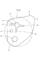
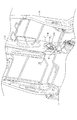
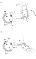
図1乃至図13は本発明の一実施形態に係るもので、図1はシートフレームの概略斜視図、図2はアームレストフレームの概略斜視図、図3はブッシュ部材を示す斜視図、図4は図1のX部拡大図、図5はプレート部材を示す斜視図、図6はプレート部材を示す平面図、図7乃至図9は本発明の一実施形態に係るプレート部材の組立過程説明図、図10はプレート部材の組込み説明図、図11は図9のA−A断面説明図、図12はアームレストの位置とカバー部に対する移動軸の位置との関係性を示す説明図、図13は狭窄突起及び変形孔の機能を示す説明図である。 1 to 13 relate to an embodiment of the present invention, FIG. 1 is a schematic perspective view of a seat frame, FIG. 2 is a schematic perspective view of an armrest frame, FIG. 3 is a perspective view showing a bush member, and FIG. FIG. 5 is a perspective view showing the plate member, FIG. 6 is a plan view showing the plate member, and FIGS. 7 to 9 are explanatory views of the assembly process of the plate member according to the embodiment of the present invention. FIG. 10 is an explanatory diagram of the plate member assembly, FIG. 11 is an AA cross-sectional explanatory diagram of FIG. 9, FIG. 12 is an explanatory diagram showing the relationship between the position of the armrest and the position of the moving shaft relative to the cover, It is explanatory drawing which shows the function of a processus | protrusion and a deformation | transformation hole.
<<車両用シートSの基礎構成>>
以下、本発明に係るシートを車両用のシートに適用した例を示す。
そして、本実施形態では、このような車両用のシートのうち、所謂「セミベンチシート」と称されるシートに適用した例を示すものであり、更に詳しくは、このセミベンチシートのうち幅方向に大きい側のシートを車両用シートSとして適用した例を説明する。
図1乃至図3を参照して、実施形態に係る車両用シートSについて説明する。
車両用シートSは、図1で示すように、シートフレームFを骨格と有するシートであり、使用時には、このシートフレームFにクッションパッドを配置するとともにその表面を表皮材で被覆した状態となるものである。
なお、図示は省略しているが、完成品には公知のヘッドレストが備えられており、このヘッドレストは、例えば、頭部の芯材(不図示)にクッションパッド及び表皮材が装着されて形成されている。また、下方からはシートバックフレーム1と連結するためのヘッドレストピラー(不図示)が、突出している。なお、符号Hは、ヘッドレストピラーを支持するピラー支持部である。
<< Basic configuration of vehicle seat S >>
Hereinafter, the example which applied the seat concerning the present invention to the seat for vehicles is shown.
And in this embodiment, the example applied to the sheet | seat called what is called a "semi-bench seat" among such vehicle seats is shown, More specifically, the width direction of this semi-bench seat is shown. An example in which the larger seat is applied as the vehicle seat S will be described.
The vehicle seat S according to the embodiment will be described with reference to FIGS. 1 to 3.
As shown in FIG. 1, the vehicle seat S is a seat having a seat frame F as a skeleton, and when used, a cushion pad is disposed on the seat frame F and the surface thereof is covered with a skin material. It is.
Although not shown, the finished product is provided with a known headrest, and this headrest is formed, for example, by attaching a cushion pad and a skin material to a core material (not shown) of the head. ing. Further, a headrest pillar (not shown) for connecting to the seat back frame 1 protrudes from below. In addition, the code | symbol H is a pillar support part which supports a headrest pillar.
車両用シートSのシートフレームFは、図1で示すように、シートバックフレーム1、シートクッションフレーム2から構成されている。
シートバックフレーム1は、乗員の背部を支持するものであり、クッションパッドと表皮材を装着されて車両用シートSのシートバックを構成する。
また、シートクッションフレーム2は、乗員の臀部を下方から支持するものであり、同様に、クッションパッドと表皮材を装着されて車両用シートSの着座部を構成する。
The seat frame F of the vehicle seat S includes a seat back frame 1 and a seat cushion frame 2 as shown in FIG.
The seat back frame 1 supports the back of the occupant, and is configured with a cushion pad and a skin material to constitute a seat back of the vehicle seat S.
The seat cushion frame 2 supports the occupant's buttocks from below, and similarly, a cushion pad and a skin material are attached to constitute a seating portion for the vehicle seat S.
そして、シートバックフレーム1の下端とシートクッションフレーム2の後端とは連結部材3,3を介して連結されており、リクライニング機構11により、シートクッションフレーム2に対するシートバックフレーム1の角度は調整可能となるように構成されている。
The lower end of the seat back frame 1 and the rear end of the seat cushion frame 2 are connected via connecting
≪シートバックフレーム≫
図1に示すように、シートバックフレーム1は、車幅方向に離隔して配置されたシートバック側サイドフレーム1a,1aと、これらの上端を架橋するように配置された略コ字形状の上部フレーム1bと、で構成された枠状(下方に開口のある枠状)の部材を基本構成としている。
上部フレーム1bは、両自由端部が各々シートバック側サイドフレーム1a,1a上端部に連結された上方に凸の略コ字型パイプであり、その上方辺にはピラー支持部Hが溶接されている。
また、シートバック側サイドフレーム1a,1aの下端部は各々、シートクッションフレーム2の後端側に、リクライニング機構11及び連結部材3,3を介して連結されている。
また、バック側サイドフレーム1a,1a間には、これと並行となるようにバック側中央フレーム1cが配置されている。
バック側中央フレーム1cの下端部分の一面側は、接続フレーム1d上端に溶接されている。
なお接続フレーム1dは、リクライニング機構11を介して、後述するクッション側中央フレーム2e後端側上方部に取付けられている。
なお、本例においては、バック側中央フレーム1cは、同様形状に形成されたフレーム片を2枚組合わせることにより中空立体形状に形成されている。
≪Seatback frame≫
As shown in FIG. 1, a seat back frame 1 includes seat back side frames 1 a and 1 a that are spaced apart in the vehicle width direction, and a substantially U-shaped upper portion that is disposed so as to bridge the upper ends thereof. The
The
Further, the lower end portions of the seat back
Further, a back-
One surface side of the lower end portion of the back side
Note that the connection frame 1d is attached to a cushion side
In this example, the back side
また、バック側中央フレーム1cの下端側の他面側(接続フレーム1dが溶接されている側と反対側の面)には、ガイド部材Gを構成するアームレスト受部材7が配設されている。
また、2個のシートバック側サイドフレーム1a,1aのうち、バック側中央フレーム1cの下端側の他面側(接続フレーム1dが溶接されている側と反対側の面)と対面する側のシートバック側サイドフレーム1aにもまた、ガイド部材Gを構成するアームレスト受部材7が配置されている。
つまり、アームレスト受部材7,7は、同高さで対向する位置に配置されている。
なお、アームレスト受部材7,7を備えるガイド部材Gの詳細な構成、及び機能は本実施形態の主要構成であるため、後に詳述する。
In addition, an
Of the two seat back
That is, the
In addition, since the detailed structure and function of the guide member G provided with the
≪シートクッションフレーム≫
図1に示すように、シートクッションフレーム2を構成する各クッション側サイドフレーム2aは、前後方向に延出した部材であり、後端部にてシートバックフレーム1と連結している。
また、左右方向一端側(左側)のクッション側サイドフレーム2aと、左右方向他端側(右側)のクッション側サイドフレーム2aとは、互いに平行な状態で左右方向に離間している。クッション側サイドフレーム2a,2a同士は、後端側で後側連結パイプ2bを介して、前端上方側で前側上部連結パイプ2cを介して、それぞれ連結している。
この後側連結パイプ2bは、車両用シートSの幅方向一端から他端に亘って伸びたパイプ部材である。
≪Seat cushion frame≫
As shown in FIG. 1, each cushion-
In addition, the cushion
The
また、前側上部連結パイプ2cは、略コ字形状に屈曲形成されたパイプ部材であり、両自由端は、クッション側サイドフレーム2a,2aの前端部に連結されている。つまり、略コ字形状の前側上部連結パイプ2cは、前側に凸となる状態で、その両自由端がクッション側サイドフレーム2a,2aの前端部に連結されている。
また、クッション側サイドフレーム2a,2aの前端下方側には角筒状の前側下部連結バー2dが架橋されている。
The front
In addition, a rectangular tube-shaped front lower connecting
このように、これらクッション側サイドフレーム2a,2a、後側連結パイプ2b、前側上部連結パイプ2c、前側下部連結バー2dとで、矩形枠状のシートクッションフレーム2が基本構成として形成される。
また、2個のクッション側サイドフレーム2a,2a間には、これらと平行となるように、クッション側中央フレーム2eが配置されている。
このクッション側中央フレーム2eは、その前端側が前側下部連結バー2dに固定されるとともに、後端側は後側連結パイプ2bを貫通させた状態で、当該後側連結パイプ2bに取付けられており、その上方にてリクライニング機構11を介して接続フレーム1d下端部に取付けられている。
In this way, the cushion-
A cushion side
The cushion side
また、クッション側サイドフレーム2a,2aの下方には、レール連結部材5,5が配設されている。
一方のクッション側サイドフレーム2aには、その下方にレール連結部材5が直接溶接されている。
他方のクッション側サイドフレーム2aの内側には下方フレーム4が配設(前側下部連結バー2dと後側連結パイプ2bとを架橋するように配設)されるとともに、この下方フレーム4の下端側にレール連結部材5が溶接されている。
なお、図示は省略するが、シートクッションフレーム2の下方には、公知のレール装置が備えられている。このレール装置は、公知の構成と同様、アッパレールとロワレールとの組合体二組により構成されており、各々のアッパレールとロワレールとの組合体は、両クッション側サイドフレーム2a,2aの下方に各々配置されている。
そして、双方のロワレールは、車体フロアに固定され、双方のアッパレールは、直接的若しくは間接的にクッション側サイドフレーム2a,2aに各々連結されている。
Rail connecting members 5 and 5 are disposed below the
The rail connecting member 5 is directly welded to the
A lower frame 4 is disposed inside the other cushion-
Although not shown, a known rail device is provided below the seat cushion frame 2. This rail device is composed of two combinations of an upper rail and a lower rail, as in the known configuration, and each of the combinations of the upper rail and the lower rail is disposed below the
Both lower rails are fixed to the vehicle body floor, and both upper rails are directly or indirectly connected to the
≪アームレストについて≫
次いで、図2により、本実施形態に係るアームレストTについて説明する。
なお、図2は、格納状態におけるアームレストTを図示したものであり、この状態においては、当該状態においては、図2に示すように、上下方向が規定される。
アームレストTは、アームレストフレーム6を骨格として有して構成された略直方体形状の部材であり、使用時には、このアームレストフレーム6にクッションパッドK1を配置するとともにその表面を表皮材K2で被覆した状態となるものである。
≪About armrest≫
Next, the armrest T according to the present embodiment will be described with reference to FIG.
FIG. 2 illustrates the armrest T in the retracted state. In this state, the vertical direction is defined in this state as shown in FIG.
The armrest T is a substantially rectangular parallelepiped member having the armrest frame 6 as a skeleton, and in use, the cushion pad K1 is disposed on the armrest frame 6 and the surface thereof is covered with the skin material K2. It will be.
アームレストフレーム6は、幅方向に離隔して配置される2個のアームレスト側サイドフレーム6a,6aと、これらの上端を架橋するように配置された略コ字形状のアームレスト側上部フレーム6bと、で構成された枠状(下方に開口のある枠状)の部材を基本構成としている。
アームレスト側上部フレーム6bは、両自由端部が各々アームレスト側サイドフレーム6a,6a上端部に連結された上方に凸の略コ字型パイプである。
なお、アームレスト側サイドフレーム6a,6aのうち、バック側中央フレーム1c側に配置される側(以下、「アームレスト側中央サイドフレーム601」と記す)は、下端部が他方のアームレスト側サイドフレーム6a(以下、「アームレスト側他方サイドフレーム602」と記す)方向に近接するように屈曲して形成されている。
つまり、アームレスト側中央サイドフレーム601は、アームレスト側上部フレーム6b下端との連結部分より若干下方位置から、アームレスト側他方サイドレーム602側へ一度屈曲して下方へ延びるよう構成されており(つまり、当該部分はアームレスト側他方サイドフレーム602側へオフセットされている)、よって、バック側中央フレーム1cとアームレスト側中央サイドフレーム601下方との距離が上方部分よりも大きくなる。このバック側中央フレーム1cとアームレスト側中央サイドフレーム601下方との空間(以下、「部材配設空間M1」と記す)に、後述するプレート部材9及びスペーサ10が配設される。この配設構成に関しては、後に詳述する。
更に、アームレスト側サイドフレーム6a,6aの下端部には、回動中心軸貫通孔61,61が各々形成されており、同様に、ストッパ軸貫通孔62,62が形成されている。
ストッパ軸貫通孔62は、アームレスト側サイドフレーム6aの下端部に形成されており、回動中心軸貫通孔61は、ストッパ軸貫通孔62よりも若干後方側上方に形成されている。
The armrest frame 6 includes two armrest-side side frames 6a and 6a that are spaced apart in the width direction, and a substantially U-shaped armrest-side
The armrest side
Of the
That is, the armrest side
Further, rotation center shaft through
The stopper shaft through-
そして、両回動中心軸貫通孔61,61間には、丸棒状の部材である回動中心軸6cが貫通するとともに、両ストッパ軸貫通孔62,62間には、丸棒状の部材であるストッパ軸6dが貫通している。
これら、回動中心軸6c及びストッパ軸6dの両端部は、両回動中心軸貫通孔61,61及び両ストッパ軸貫通孔62,62を貫通して外側へと突出している。
つまり、回動中心軸6c及びストッパ軸6dの両端部は、アームレスト側サイドフレーム6a,6aより外側に突出するとともに、クッション材及び表皮材が配置された状態においてもまた表皮材を貫通して外側へと突出している。
このアームレストTは、ガイド部材G,G間(アームレスト受部材7,7間)に回動可能に取付けられる。
つまり、回動中心軸6c及びストッパ軸6dの突出両端が、各々、ガイド部材G,G(アームレスト受部材7,7)に回動可能に軸支されることとなる。
当該構成は、本実施形態の主要構成であるため、後に詳述する。
The
Both ends of the
That is, both ends of the
The armrest T is rotatably mounted between the guide members G and G (between the
That is, the projecting both ends of the
Since this configuration is the main configuration of this embodiment, it will be described in detail later.
≪ガイド部材について:ブッシュ部材≫
ガイド部材Gは、ブッシュ部材8と、次述するアームレスト受部材7と、を有して構成されている。つまり、本実施形態に係るガイド部材Gは、ブッシュ部材8とアームレスト側受部材7とが組合わされて構成されるものである。
まず、図3により、ブッシュ部材8について説明する。
なお、ブッシュ部材8は、2個のアームレスト受部材7に各々配置されるため、本例においては、2個使用されることとなる。
ブッシュ部材8は、略扇形状の平板部材である。
この略扇形の中心付近には、ブッシュ部材側回動中心軸貫通孔81が形成されている。
そして、ブッシュ部材側回動中心軸貫通孔81からは、ブッシュ部材8の頂点方向へ向けてスリット81aが形成されている。
また、このブッシュ部材側回動中心軸貫通孔81の周縁からは、中心軸貫通孔側係止爪81bが起立している。
≪About the guide member: Bush member≫
The guide member G includes a
First, the
In addition, since the
The
A bush member side rotation center shaft through
A slit 81 a is formed from the bush member side rotation center shaft through
Further, from the periphery of the bush member side rotation center shaft through
また、このブッシュ部材側回動中心軸貫通孔81を中心とした弧形状に沿って、ブッシュ部材側ストッパ軸移動孔82が長孔として形成されている。
ストッパ軸移動孔82の両端側には、狭窄突起82a,82aが各々形成されており、この狭窄突起82a,82aの部分で、ストッパ軸移動孔82の幅が小さくなるよう構成されている。
狭窄突起82aは、ストッパ軸移動孔82の内側へ向けて凸となるように形成された略三角形状の突起部分であり、一端側に2個形成されている。
つまり、一方の狭窄突起82aは、ブッシュ部材側回動中心軸貫通孔81側からストッパ軸移動孔82の内側へ向けて凸となるように構成されるとともに、他方の狭窄突起82aはその反対側ストッパ軸移動孔82の内側へ向けて凸となるように構成されており、これら2個の狭窄突起82a,82aの頂点部分は、ブッシュ部材側ストッパ軸移動孔82内において対向している。
A bush member-side stopper
Narrowing
The
That is, one narrowing
このように構成されていることにより、2個の狭窄突起82a,82aの頂点間の距離t1は、ブッシュ部材側ストッパ軸移動孔82の他の部分の幅t2よりも小さくなる。
そして、ブッシュ部材側ストッパ軸移動孔82の他の部分の幅t2は、ストッパ軸6d外径t3よりもほんの僅かに大きくなるように構成されており、2個の狭窄突起82a,82aの頂点間の距離t1は、ストッパ軸6d外径t3よりも小さくなるように構成されている。そして、2個の狭窄突起82a,82aの頂点間の位置と直近の端部との間の空間K1はストッパ軸6dの断面とほぼ同一なるように構成されており、つまり、空間K1にはストッパ軸6dが係止されるように構成されている。
この構成は、ブッシュ部材側ストッパ軸移動孔82両端に各々備えられている。
つまり、本例においては、2個一組の狭窄突起82a,82aが、二組(両端側に各々一組ずつ)備えられている。
With this configuration, the distance t1 between the apexes of the two narrowing
The width t2 of the other part of the bush member side stopper
This configuration is provided at both ends of the bush member side stopper
That is, in this example, two sets of two narrowing
また、ブッシュ部材側ストッパ軸移動孔82の両端部周縁からは、ストッパ軸貫通孔側係止爪82b,82bが各々起立している。
このストッパ軸貫通孔側係止爪82b,82bが起立している方向は、上述した中心軸貫通孔側係止爪81bの起立方向と同一の方向であり、取付られる側のアームレスト受部材7が配設される側の方向である。
Further, stopper shaft through-hole
The direction in which the stopper shaft through-hole
また、ブッシュ部材側回動中心軸貫通孔81側に形成された狭窄突起82aの、ブッシュ部材側回動中心軸貫通孔81側には、略三角形状の変形孔83が形成されている。
この変形孔83は、その一頂点近辺が狭窄突起82aの形状に沿うように穿たれている。つまり、一頂点がブッシュ部材側ストッパ軸移動孔82側に向くように穿孔されている。
なお、本例においては、変形孔83もまた、両端部に1個ずつ(計2個)形成されている。
Further, a substantially
The
In this example, one
更に、ブッシュ部材8は、完全にフラットな部材ではなく、ブッシュ部材側ストッパ軸移動孔82が穿孔されている部分(略円弧形状側端部付近であり、以下「プレート部材非当接部D1」と記す)の肉厚が、ブッシュ部材側回動中心軸貫通孔81及び変形孔83,83が穿孔されている部分(ブッシュ部材側回動中心軸貫通孔81を中心とし、ブッシュ部材側ストッパ軸移動孔82を含まない扇形部分であり、以下「プレート部材当接部D2」と記す)に比して薄くなるように構成されている。つまり、両者の境界部分に段差部D3が形成されており、両者の肉厚が異なるよう構成されている。
これにより、後述するプレート部材9が当接するプレート部材当接部D2が肉厚となり剛性が向上するとともに、プレート部材非当接部D1は段差部D3を境に薄肉となるため、プレート部材当接部D2に面接触したプレート部材9が、ブッシュ部材側ストッパ軸移動孔82形成部分であるプレート部材非当接部D1に当接することを有効に防止することができる。
Further, the
As a result, the plate member abutting portion D2 with which the
≪ガイド部材について:アームレスト受部材≫
次いで、図4により、アームレスト受部材7について説明する。
前述の通り、アームレスト受部材7は、2個存在するが、同様の構成であるため、説明は一方にとめる。
アームレスト受部材7は、その前方側に受部材側回動中心軸貫通孔71が形成されており、この受部材側回動中心軸貫通孔71を中心とした弧形状に沿って、受部材側ストッパ軸移動孔72が長孔として形成されている。
そして、受部材側ストッパ軸移動孔72の周縁からは、ストッパ軸貫通孔側受壁72bが起立している(図10参照)。
≪About the guide member: Armrest receiving member≫
Next, the
As described above, there are two
The
And from the periphery of the receiving member side stopper
これら、受部材側回動中心軸貫通孔71と受部材側ストッパ移動孔72は、前述したブッシュ部材8に形成されたブッシュ部材側回動中心軸貫通孔81及びブッシュ部材側ストッパ軸移動孔82と同様のサイズ及び位置関係に形成されている。このため、受部材側回動中心軸貫通孔71とブッシュ部材側回動中心軸貫通孔81とが連通するとともに、受部材側ストッパ移動孔72とブッシュ部材側ストッパ軸移動孔82とが連通するように、ブッシュ部材8をアームレスト受部材7に重ねることができる。
The receiving member side rotation center shaft through
そして、ブッシュ部材8をアームレスト受部材7に重ねる際に、中心軸貫通孔側係止爪81bを受部材側回動中心軸貫通孔71に圧入係止するとともに、ストッパ軸貫通孔側係止爪82b,82bを受部材側ストッパ軸移動孔72の両端部に圧入して両端部のストッパ軸貫通孔側受壁72b内壁部分に係止することにより、ブッシュ部材8をアームレスト受部材7に取付けることができる。
この取付けの際には、スリット81a及び変形孔83が撓むことにより、効率的に取付を行うことができる。
When the
At the time of attachment, the
≪プレート部材について≫
図5及び図6により、本実施形態に係るプレート部材9について説明する。
プレート部材9は、ガイド部材Gとアームレスト側中央サイドフレーム601との間に介在して、異物侵入を防止するための部材である。
本実施形態に係るプレート部材9は、略扇形状の平板部材である。
この略扇形の中心付近には、略正方形状に穿孔されたプレート部材側回動中心軸貫通孔91(特許請求の範囲における「第三孔」に相当する)が形成されている。
このプレート部材側回動中心軸貫通孔91の開口辺の長さは、回動中心軸6cの外径よりも僅かに小さくなるように構成されており、よって、回動中心軸6cは、このプレート部材側回動中心軸貫通孔91に圧入固定される。
このように、プレート部材側回動中心軸貫通孔91を略正方形状に形成した理由を説明する。
図6に示すように、回動中心軸6cの外径より僅かに小さい一辺を持つ略正方形状のプレート部材側回動中心軸貫通孔91に、回動中心軸6cを圧入すると、このプレート部材側回動中心軸貫通孔91の各辺に、回動中心軸6cが圧接することとなるが、正方形への円形の内接であるため、正方形の頂点部分には、間隙が形成されることとなる。よって、この間隙が形成されるため、回動中心軸6cによるプレート部材9への負荷を軽減することが可能となる。
≪About plate members≫
The
The
The
In the vicinity of the center of the substantially sector shape, there is formed a plate member side rotation center axis through hole 91 (corresponding to a “third hole” in the claims) that is perforated in a substantially square shape.
The length of the opening side of the plate member side rotation center axis through
The reason why the plate member side rotation center axis through
As shown in FIG. 6, when the
そして、このプレート部材側回動中心軸貫通孔91の3頂点部分からは、3個のプレート部材側スリット91aが、放射状に各々延びるように形成されている。
このようにプレート部材側スリット91aが形成されていることにより、更に、プレート部材9への負荷を軽減することが可能となる。
Then, three plate member side slits 91a are formed so as to extend radially from the three apex portions of the plate member side rotation center axis through
By forming the plate member side slit 91a in this way, it is possible to further reduce the load on the
また、プレート部材9において、部分略円弧状の端部付近であって、車両用シートS前方側にあたる位置には、プレート部材側ストッパ軸貫通孔92(特許請求の範囲における「第四孔」に相当する)が形成されている。
このプレート部材側ストッパ軸貫通孔92の内径は、ストッパ軸6dの外径よりも僅かに大きくなるように構成されている。このように構成することにより、組付け誤差を吸収することが可能となる。
また、プレート部材側回動中心軸貫通孔91とプレート部材側ストッパ軸貫通孔92との間には、誤組防止用孔93が形成されている。
なお、この誤組防止用孔93は、プレート部材9の組付け時には、車両用シートS前方側に位置するように形成される。
Further, in the
The inner diameter of the plate member side stopper shaft through
Further, a
The
また、表皮材K2には、作業用の開口である表皮材側作業孔K21(特許請求の範囲の「作業孔」に相当する)が形成されている(図6参照)。
そして、プレート部材9において、部分略円弧状の車両用シートS後方端部付近は、表皮材側作業孔K21から外側へ露出しないよう構成されており、この露出しない部分を、「外方延出部9a」と記す。
このように、外方延出部9aが表皮材側作業孔K21から露出しない構成となっているため、この表皮材側作業孔K21からプレート部材9が外側へ飛び出すことを有効に防止することができる。
Further, the skin material K2 is formed with a skin material side work hole K21 (corresponding to “work hole” in the claims), which is an opening for work (see FIG. 6).
In the
Thus, since the outward extending
≪アームレスト取付状態について≫
図4、図7乃至図11により、アームレストTの取付け状態について説明する。
まず、上述したように、ブッシュ部材8,8をアームレスト受部材7,7に取付けて、ガイド部材G,Gを構成する。
なお、ガイド部材G,Gの形成は、双方同様の構成であるため、一方の説明にとめる。
まず、図4に示すように、アームレスト受部材7をバック側中央フレーム1cに、溶接により取付ける(他方は、シートバック側サイドフレーム1aに取付ける)。
そして、図11に示すように、ブッシュ部材8を、アームレスト受部材7に組付ける。
このとき、受部材側回動中心軸貫通孔71とブッシュ部材側回動中心軸貫通孔81とが連通するように(以下、この連通孔を「第一連通孔H1」と記す)配置されるとともに、受部材側ストッパ移動孔72とブッシュ部材側ストッパ軸移動孔82とが連通するように(以下、この連通孔を「第二連通孔H2」と記す)配置される。
なお、この第一連通孔H1と第二連通孔H2が、特許請求の範囲の「第一孔」と「第二孔」に各々相当する。
このようにブッシュ部材8をアームレスト受部材7に取付け、第一連通孔H1に、回動中心軸6cの端部が回動可能に挿入されることとなる。また、同時に、第二連通孔H2に、ストッパ軸6dの端部が長孔に沿って移動可能に挿入されることとなる。
≪About armrest mounting condition≫
The mounting state of the armrest T will be described with reference to FIGS. 4 and 7 to 11.
First, as described above, the
In addition, since formation of the guide members G and G is the same structure in both, it will be stopped in one description.
First, as shown in FIG. 4, the
Then, as shown in FIG. 11, the
At this time, the receiving member side rotation center shaft through
The first communication hole H1 and the second communication hole H2 correspond to “first hole” and “second hole” in the claims, respectively.
Thus, the
次いで、プレート部材9の位置について説明する。
このプレート部材9は、アームレスト側サイドフレーム6a,6aのうち、バック側中央フレーム1c側に配設される側であるアームレスト側中央サイドフレーム601側にのみ備えられる。他方には、プレート部材9及び後述するスペーサ10は配置されず、アームレスト側他方サイドレーム602とブッシュ部材8が直接対面する構成となる。
Next, the position of the
The
図7、図10、図11に示すように、プレート部材9は、ブッシュ部材8に積層するように配置される。
このとき、回動中心軸6cは、プレート部材側回動中心軸貫通孔91に圧入されるとともに、ストッパ軸6dは、プレート部材側ストッパ軸貫通孔92に挿通されることとなる。
なお、図7に示したような初期状態(アームレストTが格納状態となる位置にある状態)において、外方延出部9aは、後方に配置されるよう積層され、このように積層されると、誤組防止用孔93が前方に位置することとなる。
As shown in FIGS. 7, 10, and 11, the
At this time, the
In the initial state as shown in FIG. 7 (the state in which the armrest T is in the retracted state), the outward extending
また、本実施形態においては、輪バネ状のスペーサ10が配置されている。
このスペーサ10は、略円筒形状に構成されるとともに、その側面に両開口間をわたるスペーサスリット10aが形成された輪バネである。そして、そのスペーサスリット10aから回動中心軸6cを内孔へと押し込むことにより、回動中心軸6cにスペーサ10が取付けられる。つまり、スペーサスリット10aの復元力により、回動中心軸6cを把持できる構成をとることとなる。
Further, in the present embodiment, a ring spring-
The
そして、図8乃至図11に示すように、このスペーサ10は、プレート部材9とアームレスト側中央サイドフレーム601との間に介在するように、回動中心軸6cに取付けられている。
なお、このとき、前述の通り、アームレスト側中央サイドフレーム601の下方は、アームレスト側他方サイドレーム602側へオフセットされているため、バック側中央フレーム1cとアームレスト側中央サイドフレーム601下方と間に部材配設空間M1が形成されており、このため、この部材配設空間M1に、プレート部材9及びスペーサ10を納めることができる。
As shown in FIGS. 8 to 11, the
At this time, as described above, the lower part of the armrest side
≪アームレストの動とそれに付随する構成≫
アームレストTの動きについて、図12により説明する。
なお、以下、ガイド部材GとアームレストTとの関連性による説明であり、プレート部材9及びスペーサ10は、回動中心軸6c及びストッパ軸6dの回動及び変位に付随して連れ回るだけであるため、プレート部材9及びスペーサ10の図示は省略している。
ブッシュ部材8は上記の通りアームレスト受部材7に取付けられており不動である。
図12(a)は、アームレストTが車両フロアに対して略垂直に立ち上がった格納状態であるが、このときには、ストッパ軸6dは、受部材側ストッパ移動孔72とブッシュ部材側ストッパ軸移動孔82との連通孔の一端(下端)側に配置されている。
この状態で、アームレストTを矢印方向へと回動させる(倒す)と、回動中心軸6cの位置は不動であるが、ストッパ軸6dは、受部材側ストッパ移動孔72とブッシュ部材側ストッパ軸移動孔82との連通孔内を矢印方向に移動する。
≪The movement of the armrest and the accompanying structure≫
The movement of the armrest T will be described with reference to FIG.
Hereinafter, the description is based on the relationship between the guide member G and the armrest T, and the
The
FIG. 12A shows a retracted state in which the armrest T rises substantially perpendicularly to the vehicle floor. At this time, the
In this state, when the armrest T is rotated (turned down) in the direction of the arrow, the position of the
≪アームレストの格納位置と使用位置との変位について≫
そして、図12(b)に示す使用位置へとアームレストTが展開した状態では、ストッパ軸6dは、受部材側ストッパ移動孔72とブッシュ部材側ストッパ軸移動孔82との連通孔の他端(上端)側へと配置されることとなる。
なお、受部材側ストッパ移動孔72とブッシュ部材側ストッパ軸移動孔82との連通孔の両端位置では、これ以上、ストッパ軸6dは移動することができないので、両端位置で格納位置及び使用位置となり、アームレストTのこれ以上の回動は禁止される。
≪Displacement between armrest retracted position and use position≫
In the state where the armrest T is deployed to the use position shown in FIG. 12B, the
In addition, since the
次いで、図13により、ストッパ機能と変位完了地点の認知機構について説明する。
上述の通り、本例におけるアームレストTは、格納位置と使用位置との間を変位し、終着点である格納位置及び使用位置に到達した際には、ストッパ軸6dが受部材側ストッパ移動孔72とブッシュ部材側ストッパ軸移動孔82との連通孔の両端位置にそれぞれ配置された状態となる。
このように、ストッパ軸6dが受部材側ストッパ移動孔72とブッシュ部材側ストッパ軸移動孔82との連通孔の両端位置に到達する際には、当該位置が回動完了点であることを認知させるための機構が本例においては存在する。
Next, a stopper function and a mechanism for recognizing a displacement completion point will be described with reference to FIG.
As described above, the armrest T in this example is displaced between the storage position and the use position, and when the armrest T reaches the storage position and the use position, which are the end points, the
As described above, when the
上述の通り、2個の狭窄突起82a,82aの頂点間の距離t1は、ブッシュ部材側ストッパ軸移動孔82の他の部分の幅t2よりも小さくなるよう構成されており、同様に、2個の狭窄突起82a,82aの頂点間の距離t1は、ストッパ軸6dの外径t3よりも小さくなるように構成されている。
このため、ストッパ軸6dが移動して、2個の狭窄突起82a,82aの頂点間に到達すると、図13(b)に示すように、ストッパ軸6dは、2個の狭窄突起82a,82aの頂点間を押し広げながら当該位置を通過することとなる。
つまり、このとき、白抜き矢印方向に2個の狭窄突起82a,82aの頂点間を押し広げる向きに力がかかり、当該力の分、アームレストTを回動させる操作力が余分に必要となる。
As described above, the distance t1 between the apexes of the two narrowing
Therefore, when the
That is, at this time, a force is applied in the direction of pushing the space between the apexes of the two narrowing
なお、このとき、本例においては、狭窄突起82aに近接して変形孔83が形成されているため、この変形孔83が変形することにより、白抜き矢印方向の力を吸収でき、よって、ブッシュ部材8自体が変形することを有効に防止することができる。
また、反対側の狭窄突起82a(外側の狭窄突起82a)側近傍は、外側へと撓むことにより白抜き矢印方向の力を逃がすことができる。なお、当該位置に内側に凸となるような切欠き部を形成してより効率的に白抜き矢印方向の力を逃がすように構成してもよい。
そして、更に、力を加えると、図13(c)に示すように、ストッパ軸6dが受部材側ストッパ移動孔72とブッシュ部材側ストッパ軸移動孔82との連通孔の一端部(上端部)に当接して、ストッパ軸6dがそれ以上矢印方向に移動することが禁止される。
なお、このとき、2個の狭窄突起82a,82aの両頂点と、ストッパ軸6dとの当接は解除され、変形していた変形孔83は復元される。
At this time, in this example, since the
Also, the force in the direction of the white arrow can be released by bending the vicinity of the
When a force is further applied, as shown in FIG. 13C, the
At this time, the contact between the two apexes of the two narrowing
このように、図13(b)から図13(c)に至る工程において、操作者の操作力は、大から小へと軽減される。つまり、図13(b)の段階では、2個の狭窄突起82a,82aの頂点間を押し広げるための力が必要となるため、アームレストTを回動する操作力を増加させる必要があり、図13(c)の段階で、2個の狭窄突起82a,82aの両頂点との接触が外れるため、操作力が軽減される。
これにより、操作者は、回動操作が終了したことを認知することができる。
換言すると、大きい力から小さい力へと変換するとともに、2個の狭窄突起82a,82aがもとの位置へと復元する手ごたえを感じることができ、所謂「クリック感」を認識することができる。
よって、使用位置において、ストッパ軸6dのそれ以上の回動を禁止するとともに、使用位置への変位完了を確実に認知させることができる。
なお、以上、使用位置について説明したが、格納位置においても、同様であるため説明は省略する。
Thus, in the process from FIG. 13B to FIG. 13C, the operator's operating force is reduced from large to small. That is, at the stage of FIG. 13B, a force is required to push and spread between the apexes of the two
Thereby, the operator can recognize that the rotation operation has been completed.
In other words, the force can be converted from a large force to a small force, and the two
Therefore, it is possible to prohibit further rotation of the
In addition, although the use position was demonstrated above, since it is the same also in a storage position, description is abbreviate | omitted.
なお、上記各実施形態では、具体例としての説明を行ったものであるが、本発明はこれに限定されることはなく、本発明の趣旨を逸脱しない範囲において、各部材の構成配置等は変更することが可能である。
例えば、狭窄突起82aの形状は、円弧状、多角形状等どのような形状であってもよいし、変形孔83の形状もまた、円形状、多角形状等どのような形状であってもよい。
また、本例においては、格納位置と使用位置とに停止位置を設けたが、これに限られることはなく、必要であれば、途中の段階等に同様に狭窄突起82aを設けて停止位置及びクリック感を付与してもよい。
In each of the above embodiments, the description has been given as a specific example. However, the present invention is not limited to this, and the configuration and arrangement of each member are within the scope of the present invention. It is possible to change.
For example, the shape of the
In this example, the stop position is provided at the storage position and the use position. However, the present invention is not limited to this, and if necessary, the stop position and A click feeling may be imparted.
S 車両用シート
K1 クッションパッド
K2 表皮材
K21 表皮材側作業孔(作業孔)
F シートフレーム
1 シートバックフレーム
1a シートバック側サイドフレーム
1b 上部フレーム
1c バック側中央フレーム
1d 接続フレーム
H ピラー支持部
2 シートクッションフレーム
2a クッション側サイドフレーム
2b 後側連結パイプ
2c 前側上部連結パイプ
2d 前側下部連結バー
2e クッション側中央フレーム
3 連結部材
4 下方フレーム
5 レール連結部材
T アームレスト
6 アームレストフレーム
6a アームレスト側サイドフレーム
601 アームレスト側中央サイドフレーム
602 アームレスト側他方サイドレーム
61 回動中心軸貫通孔
62 ストッパ軸貫通孔
6b アームレスト側上部フレーム
6c 回動中心軸(第一軸)
6d ストッパ軸(第二軸)
G ガイド部材
7 アームレスト受部材
71 受部材側回動中心軸貫通孔(第一孔)
72 受部材側ストッパ軸移動孔(第二孔)
72b ストッパ軸貫通孔側受壁
8 ブッシュ部材
81 ブッシュ部材側回動中心軸貫通孔(第一孔)
81a スリット
81b 中心軸貫通孔側係止爪
82 ブッシュ部材側ストッパ軸移動孔(第二孔)
82a 狭窄突起
82b ストッパ軸貫通孔側係止爪
83 変形孔
D1 プレート部材非当接部
D2 プレート部材当接部
D3 段差部
9 プレート部材
9a 外方延出部
91 プレート部材側回動中心軸貫通孔(第三孔)
91a プレート部材側スリット
92 プレート部材側ストッパ軸貫通孔(第四孔)
93 誤組防止用孔
10 スペーサ
10a スペーサスリット
11 リクライニング機構
H1 第一連通孔(第一孔)
H2 第二連通孔(第二孔)
M1 部材配設空間
S Vehicle seat K1 Cushion pad K2 Skin material K21 Skin material side work hole (work hole)
F Seat frame 1 Seat back
6d Stopper shaft (second shaft)
72 Receiving member side stopper shaft moving hole (second hole)
72b Stopper shaft through hole
91a Plate member side slit 92 Plate member side stopper shaft through hole (fourth hole)
93
H2 Second communication hole (second hole)
M1 member installation space
Claims (13)
前記アームレストの前記一端側には、回動中心となる第一軸が前記シートの幅方向に貫通するように配置されるとともに、前記一端側には、該第一軸と略平行に第二軸が貫通しており、
前記第一軸は、前記シートバックの骨格であるシートバックフレームに固定されたガイド部材に形成された第一孔に、回動可能に支持されるとともに、前記第二軸は、前記第一孔を中心とした部分円弧軌跡に沿って形成された長孔状の第二孔に沿って移動可能となるように該第二孔に挿通されており、
前記アームレストの側面側と前記ガイド部材との間には、前記第二孔の少なくとも一部を覆うプレート部材が備えられ、
前記第一軸及び前記第二軸は、前記プレート部材を貫通して固定され、
前記プレート部材には、第三孔及び第四孔が形成されており、該第三孔には、前記第一軸または前記第二軸のうちいずれか一方が圧入固定されるとともに、前記第一軸または前記第二軸の他方が、該他方の軸外径よりも大径となるよう穿孔されている前記第四孔に貫通していることを特徴とするアームレストを備えたシート。 A seat provided with an armrest that is pivotally displaced about one end side between a retracted position retracted in a posture along the seat back and a deployed position where the free end side projects forward from the seat back. There,
Said one end of the armrest, with the first axis serving as the rotation center is disposed so as to penetrate in the width direction of the sheet, said one end, said first axis substantially parallel to the second axis Has penetrated,
The first shaft is rotatably supported by a first hole formed in a guide member fixed to a seat back frame that is a skeleton of the seat back, and the second shaft is supported by the first hole. Is inserted into the second hole so as to be movable along a long hole-shaped second hole formed along a partial arc locus centering on
Between the side surface side of the armrest and the guide member, a plate member covering at least a part of the second hole is provided ,
The first shaft and the second shaft are fixed through the plate member,
A third hole and a fourth hole are formed in the plate member, and either the first shaft or the second shaft is press-fitted and fixed to the third hole. A seat provided with an armrest, wherein the other of the shaft and the second shaft passes through the fourth hole that is perforated to have a larger diameter than the outer diameter of the other shaft .
前記アームレスト受部材と前記ブッシュ部材にはそれぞれ、前記第一孔と前記第二孔が形成され、
前記ブッシュ部材の前記第一孔の周縁から第一係止爪が起立するように設けられると共に、該第一孔から外方に向けてスリットが形成され、
前記ブッシュ部材の前記第二孔の両端部周縁から第二係止爪が起立するように設けられ、
前記第一係止爪は、前記アームレスト受部材の前記第一孔に圧入され、
前記第二係止爪は、前記アームレスト受部材の前記第二孔に圧入されることを特徴とする請求項1乃至請求項3のいずれか一項に記載のアームレストを備えたシート。 The guide member has an armrest receiving member and a bush member,
The armrest receiving member and the bush member are respectively formed with the first hole and the second hole,
The first locking claw is provided so as to stand up from the periphery of the first hole of the bush member, and a slit is formed outward from the first hole,
The second locking claw is provided so as to stand up from the peripheral edge of both ends of the second hole of the bush member,
The first locking claw is press-fitted into the first hole of the armrest receiving member,
The seat with the armrest according to any one of claims 1 to 3 , wherein the second locking claw is press-fitted into the second hole of the armrest receiving member .
前記第一孔が形成されたプレート部材非当接部と、
前記第二孔が形成されたプレート部材当接部と、を有し、
前記プレート部材非当接部と前記プレート部材当接部の境界は、前記第二孔に沿っており、
前記プレート部材非当接部の肉厚は、前記プレート部材当接部の肉厚よりも厚いことを特徴とする請求項1乃至請求項6いずれか一項に記載のアームレストを備えたシート。 The guide member is
A plate member non-contact portion in which the first hole is formed;
A plate member contact portion in which the second hole is formed,
The boundary between the plate member non-contact portion and the plate member contact portion is along the second hole,
The thickness of the plate member noncontact portion, a sheet having a armrest as claimed in any one of claims 1 to claim 6, wherein thicker than the thickness of the plate member abutment.
前記プレート部材が設けられる側の前記アームレスト側サイドフレームの少なくとも一部は、前記プレート部材が設けられない側の前記アームレスト側サイドフレームの配設方向側にオフセットして配設されることを特徴とする請求項9に記載のアームレストを備えたシート。 The armrest frame includes two armrest side frames that are spaced apart from each other in the width direction of the seat, and an armrest side upper frame that bridges the upper ends of the two armrest side frames. Has been
At least a portion of the armrest side side frame of the side where the plate member is provided, and wherein the plate member is disposed to be offset in the arranged direction of the armrest side side frame of the Never side provided A seat provided with the armrest according to claim 9.
前記表皮材には、前記第一軸の周辺を露出させるように開口する作業孔が形成されており、
前記プレート部材は、前記作業孔よりも外方向に延びる外方延出部を備えていることを特徴とする請求項9又は請求項10に記載のアームレストを備えたシート。 The armrest is configured to include the armrest frame, a pad provided around the armrest frame, and a skin material covering the pad,
The skin material has a working hole that opens to expose the periphery of the first shaft,
11. The seat with an armrest according to claim 9, wherein the plate member includes an outwardly extending portion that extends outward from the work hole.
Priority Applications (5)
| Application Number | Priority Date | Filing Date | Title |
|---|---|---|---|
| JP2015082866A JP6159751B2 (en) | 2015-04-14 | 2015-04-14 | Seat with armrest |
| PCT/JP2016/061918 WO2016167288A1 (en) | 2015-04-14 | 2016-04-13 | Seat provided with armrest |
| CN201680019357.1A CN107428276B (en) | 2015-04-14 | 2016-04-13 | The seat for having handrail |
| US15/564,822 US10493886B2 (en) | 2015-04-14 | 2016-04-13 | Seat provided with armrest |
| EP16780079.6A EP3284632B1 (en) | 2015-04-14 | 2016-04-13 | Seat provided with armrest |
Applications Claiming Priority (1)
| Application Number | Priority Date | Filing Date | Title |
|---|---|---|---|
| JP2015082866A JP6159751B2 (en) | 2015-04-14 | 2015-04-14 | Seat with armrest |
Publications (2)
| Publication Number | Publication Date |
|---|---|
| JP2016199240A JP2016199240A (en) | 2016-12-01 |
| JP6159751B2 true JP6159751B2 (en) | 2017-07-05 |
Family
ID=57125871
Family Applications (1)
| Application Number | Title | Priority Date | Filing Date |
|---|---|---|---|
| JP2015082866A Active JP6159751B2 (en) | 2015-04-14 | 2015-04-14 | Seat with armrest |
Country Status (5)
| Country | Link |
|---|---|
| US (1) | US10493886B2 (en) |
| EP (1) | EP3284632B1 (en) |
| JP (1) | JP6159751B2 (en) |
| CN (1) | CN107428276B (en) |
| WO (1) | WO2016167288A1 (en) |
Families Citing this family (9)
| Publication number | Priority date | Publication date | Assignee | Title |
|---|---|---|---|---|
| JP6359581B2 (en) * | 2016-03-15 | 2018-07-18 | 株式会社タチエス | Armrest and seat with armrest |
| JP6262279B2 (en) * | 2016-04-22 | 2018-01-17 | テイ・エス テック株式会社 | Vehicle seat |
| JP6834410B2 (en) * | 2016-11-29 | 2021-02-24 | トヨタ紡織株式会社 | Vehicle seat |
| JP6726113B2 (en) * | 2017-01-24 | 2020-07-22 | スズキ株式会社 | Structure of vehicle seat frame |
| JP7235432B2 (en) * | 2017-05-22 | 2023-03-08 | トヨタ紡織株式会社 | vehicle seat |
| US10227027B2 (en) * | 2017-06-30 | 2019-03-12 | Lear Corporation | Seat back with pivotable armrest and armrest restrictor |
| CN109109707A (en) * | 2018-09-26 | 2019-01-01 | 东风汽车集团有限公司 | A kind of arta vehicle seat unit that handrail extends automatically and the automobile containing the armchair structure |
| KR20210068651A (en) * | 2019-12-02 | 2021-06-10 | 현대자동차주식회사 | Center hinge assembly for rear seat of vehicle |
| CN114435212A (en) | 2020-10-30 | 2022-05-06 | 明门瑞士股份有限公司 | Fixing device for an armrest of a motor vehicle seat and motor vehicle seat |
Family Cites Families (23)
| Publication number | Priority date | Publication date | Assignee | Title |
|---|---|---|---|---|
| JPS62113751U (en) * | 1986-01-13 | 1987-07-20 | ||
| US4953259A (en) * | 1988-07-11 | 1990-09-04 | Prince Corporation | Armrest torque control |
| US4848840A (en) * | 1988-08-11 | 1989-07-18 | Tachi-S Co., Ltd. | Locking mechanism for armrest |
| US5292171A (en) * | 1992-06-01 | 1994-03-08 | Lear Seating Corporation | Vehicle seat armrest bracket and cover assembly |
| JP3030238B2 (en) * | 1995-08-30 | 2000-04-10 | 株式会社コムラ製作所 | Armrest structure |
| JP3406130B2 (en) * | 1995-09-21 | 2003-05-12 | 株式会社タチエス | Seat backs used for car rear seats |
| US5669107A (en) * | 1996-07-16 | 1997-09-23 | Lear Corporation | Friction detent apparatus for seat accessory |
| US5752739A (en) * | 1996-09-30 | 1998-05-19 | Tachi-S Co., Ltd. | Mounting for an armrest in seat |
| JPH1118874A (en) * | 1997-06-27 | 1999-01-26 | Ikeda Bussan Co Ltd | Arm rest for vehicle |
| US6328384B1 (en) * | 1998-05-25 | 2001-12-11 | Ikeda Bussan Co., Ltd. | Coupling structure between seatback and armrest for vehicle |
| JP2002306275A (en) | 2001-04-11 | 2002-10-22 | Johnson Controls Automotive Systems Corp | Seatback with armrest |
| US6572188B2 (en) * | 2001-11-07 | 2003-06-03 | Tachi-S Co., Ltd. | Arrangement for supporting rotation adjustment mechanism of rotary body in vehicle seat |
| US7178865B2 (en) * | 2004-09-24 | 2007-02-20 | Lear Corporation | Center occupant armrest actuated head restraint |
| JP5023613B2 (en) | 2006-08-23 | 2012-09-12 | マツダ株式会社 | Storage structure for vehicle seat |
| US20090167070A1 (en) * | 2007-12-28 | 2009-07-02 | Toyota Motor Engineering & Manufacturing North America, Inc. | Armrest For Motor Vehicle Seat Assembly |
| JP5446364B2 (en) * | 2009-03-25 | 2014-03-19 | トヨタ紡織株式会社 | Vehicle seat with armrest |
| DE102009053537B4 (en) * | 2009-11-18 | 2014-05-15 | F.S. Fehrer Automotive Gmbh | Swiveling armrest for use in a vehicle |
| JP5607352B2 (en) * | 2009-12-28 | 2014-10-15 | テイ・エス テック株式会社 | Bearing structure with resin bush |
| DE112009005491T5 (en) * | 2009-12-30 | 2012-10-04 | Lear Corporation | Mounting assembly and misalignment indicator for armrests |
| JP5665435B2 (en) * | 2010-09-02 | 2015-02-04 | テイ・エス テック株式会社 | Vehicle seat |
| JP6262279B2 (en) * | 2016-04-22 | 2018-01-17 | テイ・エス テック株式会社 | Vehicle seat |
| US10391904B2 (en) * | 2016-09-08 | 2019-08-27 | Ford Global Technologies, Llc | Inertia latch for a vehicle armrest using a spring loaded cam |
| JP7235432B2 (en) * | 2017-05-22 | 2023-03-08 | トヨタ紡織株式会社 | vehicle seat |
-
2015
- 2015-04-14 JP JP2015082866A patent/JP6159751B2/en active Active
-
2016
- 2016-04-13 CN CN201680019357.1A patent/CN107428276B/en active Active
- 2016-04-13 US US15/564,822 patent/US10493886B2/en active Active
- 2016-04-13 EP EP16780079.6A patent/EP3284632B1/en active Active
- 2016-04-13 WO PCT/JP2016/061918 patent/WO2016167288A1/en active Application Filing
Also Published As
| Publication number | Publication date |
|---|---|
| US20180118069A1 (en) | 2018-05-03 |
| CN107428276B (en) | 2019-06-25 |
| EP3284632A4 (en) | 2018-04-04 |
| EP3284632B1 (en) | 2020-06-03 |
| WO2016167288A1 (en) | 2016-10-20 |
| JP2016199240A (en) | 2016-12-01 |
| CN107428276A (en) | 2017-12-01 |
| EP3284632A1 (en) | 2018-02-21 |
| US10493886B2 (en) | 2019-12-03 |
Similar Documents
| Publication | Publication Date | Title |
|---|---|---|
| JP6159751B2 (en) | Seat with armrest | |
| JP6055836B2 (en) | Headrest | |
| WO2014192824A1 (en) | Vehicular seat | |
| JP7443957B2 (en) | vehicle seat | |
| US20050012367A1 (en) | Seat system | |
| JP2006528111A5 (en) | ||
| JP2014210532A (en) | Seat for vehicle | |
| WO2015190274A1 (en) | Vehicle seat | |
| JP2012030742A (en) | Vehicle seat equipped with buckle combination | |
| JP6922787B2 (en) | Release lever for slide device | |
| WO2012093635A1 (en) | Stowable rear seat | |
| JP4403953B2 (en) | Retractable seat for vehicle | |
| JP2002104039A (en) | Pop-up seat | |
| JP2010149822A (en) | Vehicular seat | |
| JP2019085082A (en) | Vehicle seat | |
| JP6430216B2 (en) | Vehicle seat | |
| JP6852630B2 (en) | Vehicle seat | |
| JP5446739B2 (en) | Reclining device for vehicle seat | |
| JP6272152B2 (en) | Vehicle seat | |
| JP2017019473A (en) | Vehicle seat | |
| JP2016203951A (en) | Vehicular seat | |
| JPWO2017203939A1 (en) | Vehicle seat | |
| JP6318014B2 (en) | Vehicle seat | |
| WO2018055816A1 (en) | Rail mechanism | |
| JP2006264428A (en) | Seat supporting structure |
Legal Events
| Date | Code | Title | Description |
|---|---|---|---|
| A131 | Notification of reasons for refusal |
Free format text: JAPANESE INTERMEDIATE CODE: A131 Effective date: 20170314 |
|
| A521 | Request for written amendment filed |
Free format text: JAPANESE INTERMEDIATE CODE: A523 Effective date: 20170427 |
|
| TRDD | Decision of grant or rejection written | ||
| A01 | Written decision to grant a patent or to grant a registration (utility model) |
Free format text: JAPANESE INTERMEDIATE CODE: A01 Effective date: 20170516 |
|
| A61 | First payment of annual fees (during grant procedure) |
Free format text: JAPANESE INTERMEDIATE CODE: A61 Effective date: 20170612 |
|
| R150 | Certificate of patent or registration of utility model |
Ref document number: 6159751 Country of ref document: JP Free format text: JAPANESE INTERMEDIATE CODE: R150 |
|
| R250 | Receipt of annual fees |
Free format text: JAPANESE INTERMEDIATE CODE: R250 |
|
| R250 | Receipt of annual fees |
Free format text: JAPANESE INTERMEDIATE CODE: R250 |
|
| R250 | Receipt of annual fees |
Free format text: JAPANESE INTERMEDIATE CODE: R250 |
|
| R250 | Receipt of annual fees |
Free format text: JAPANESE INTERMEDIATE CODE: R250 |
|
| S111 | Request for change of ownership or part of ownership |
Free format text: JAPANESE INTERMEDIATE CODE: R313117 |
|
| R350 | Written notification of registration of transfer |
Free format text: JAPANESE INTERMEDIATE CODE: R350 |