EP3284632A1 - Seat provided with armrest - Google Patents
Seat provided with armrest Download PDFInfo
- Publication number
- EP3284632A1 EP3284632A1 EP16780079.6A EP16780079A EP3284632A1 EP 3284632 A1 EP3284632 A1 EP 3284632A1 EP 16780079 A EP16780079 A EP 16780079A EP 3284632 A1 EP3284632 A1 EP 3284632A1
- Authority
- EP
- European Patent Office
- Prior art keywords
- armrest
- hole
- shaft
- seat
- frame
- Prior art date
- Legal status (The legal status is an assumption and is not a legal conclusion. Google has not performed a legal analysis and makes no representation as to the accuracy of the status listed.)
- Granted
Links
Images


Classifications
-
- B—PERFORMING OPERATIONS; TRANSPORTING
- B60—VEHICLES IN GENERAL
- B60N—SEATS SPECIALLY ADAPTED FOR VEHICLES; VEHICLE PASSENGER ACCOMMODATION NOT OTHERWISE PROVIDED FOR
- B60N2/00—Seats specially adapted for vehicles; Arrangement or mounting of seats in vehicles
- B60N2/75—Arm-rests
- B60N2/753—Arm-rests movable to an inoperative position
- B60N2/757—Arm-rests movable to an inoperative position in a recess of the back-rest
-
- A—HUMAN NECESSITIES
- A47—FURNITURE; DOMESTIC ARTICLES OR APPLIANCES; COFFEE MILLS; SPICE MILLS; SUCTION CLEANERS IN GENERAL
- A47C—CHAIRS; SOFAS; BEDS
- A47C7/00—Parts, details, or accessories of chairs or stools
- A47C7/54—Supports for the arms
-
- A—HUMAN NECESSITIES
- A47—FURNITURE; DOMESTIC ARTICLES OR APPLIANCES; COFFEE MILLS; SPICE MILLS; SUCTION CLEANERS IN GENERAL
- A47C—CHAIRS; SOFAS; BEDS
- A47C7/00—Parts, details, or accessories of chairs or stools
- A47C7/54—Supports for the arms
- A47C7/543—Supports for the arms movable to inoperative position
-
- B—PERFORMING OPERATIONS; TRANSPORTING
- B60—VEHICLES IN GENERAL
- B60N—SEATS SPECIALLY ADAPTED FOR VEHICLES; VEHICLE PASSENGER ACCOMMODATION NOT OTHERWISE PROVIDED FOR
- B60N2/00—Seats specially adapted for vehicles; Arrangement or mounting of seats in vehicles
- B60N2/68—Seat frames
- B60N2/682—Joining means
-
- B—PERFORMING OPERATIONS; TRANSPORTING
- B60—VEHICLES IN GENERAL
- B60N—SEATS SPECIALLY ADAPTED FOR VEHICLES; VEHICLE PASSENGER ACCOMMODATION NOT OTHERWISE PROVIDED FOR
- B60N2/00—Seats specially adapted for vehicles; Arrangement or mounting of seats in vehicles
- B60N2/75—Arm-rests
Definitions
- the present invention relates to a seat provided with an armrest and, more specifically, to a seat provided with an armrest which is designed so as to be capable of being deployed and stored with respect to the seat.
- a vehicular seat on which an occupant is seated is disposed, and such a vehicular seat is often provided with an armrest.
- such an armrest is sometimes capable of being displaced between a stored position and a deployed (usage) position.
- an armrest is provided in a central portion of a rear seat.
- These armrests are configured so as to be capable of being displaced between a stored position where the armrest is stored along a seat back (that is, it is disposed so as to rise in an up and down direction) and a usage (deployed) position where the armrest is deployed in a position substantially perpendicular to the seat back.
- This displacement is performed by pivoting the armrest around an one end (which is a lower end side at the time of storage and is a rear end side at the time of deployment) of the armrest as a fulcrum.
- the one end side (which is the lower end side at the time of storage and is the rear end side at the time of deployment) of the armrest is rotatably supported so as to be pivotable with respect to the seat back, and a free end side (which is an upper end side at the time of storage and is a front end side at the time of deployment) is pivoted drawing a circular arcuate locus around the one end side, thereby being displaced between the stored position and the usage (deployed) position.
- a recessed portion in which the armrest can be stored at the time of storage of the armrest is formed, or a gap between the rear seats divided into two parts serves as a storage space of the armrest.
- the armrest which is formed so as to be capable of being displaced between the stored position and the usage (deployed) position is used for the vehicular seat, the armrest is configured so as to be pivoted about the one end side as a pivot center, and therefore there was a possibility that foreign matter enters the interior in the vicinity of the pivot portion.
- An object of the present invention is to solve the above problems and provide, in an armrest capable of being displaced between a stored position and a deployed position, a seat provided with an armrest capable of preventing foreign matter from entering the interior thereof through a gap formed between the armrest (in particular, the vicinity of the center of displacement thereof) and a mounted portion.
- another object of the present invention is to provide, in an armrest capable of being displaced between a stored position and a deployed position, a seat provided with an armrest for which a displacement completion point to each position is recognizable.
- a seat provided with an armrest which is pivotally displaced around one end side between a stored position where it is retracted in a posture along a seat back and a deployed position where it is deployed to a position where a free end side projects forwardly from the seat back, in which: on the one end side of the armrest, a first shaft serving a pivot center is disposed so as to pass through in a width direction of the seat, and a second shaft passes through the one end side substantially parallel to the first shaft; the first shaft is pivotably supported by a first hole formed in a guide member fixed to a seat back frame which is a framework of the seat back, and the second shaft is inserted into a long hole-shaped second hole formed along a partial circular arc locus around the first hole so as to be movable along the second hole; and between a side surface side of the armrest and the guide member, a plate member which covers at least a part of the second hole is
- the first shaft and the second shaft are projected from one end of the armrest, and these projection ends are rotatably supported on a skeleton side (which is the guide member fixed to the seat back frame, in the present invention).
- the armrest pivots around this pivot center shaft, and by such a configuration, a gap is formed between the guide member and the side surface of the armrest.
- the plate member is interposed between the guide member and the side surface of the armrest, the second hole portion through which the second shaft passes is covered, and foreign matter can be effectually prevented from entering through the gap between the guide member and the side surface of the armrest.
- the second shaft is moved in the second hole which is a long hole in a shape along the partial circular arc locus.
- both end portions of the second hole which is the long hole become regulating points of movement, and thereby capable of defining a range that the armrest pivots.
- the armrest can be prohibited from pivoting (overturning) beyond the stored position and the deployed position, and therefore, by preventing foreign matter from entering that portion, the operation of the armrest can be effectually prevented from being inhibited due to foreign matter which becomes an obstacle, and the operation of the armrest can be more accurately performed.
- the plate member can be disposed on the armrest side with a simple configuration.
- a third hole and a fourth hole are formed in the plate member, one of the first shaft and the second shaft is press-fitted and fixed to the third hole, and the other of the first shaft and the second shaft passes through the fourth hole perforated so as to have a larger diameter than a shaft outer diameter of the other.
- the one of the first shaft and the second shaft is press-fitted into the third hole bored into a substantially square shape which is configured by a side length smaller than a shaft outer diameter of the one.
- a thickness of a peripheral portion of the first hole is formed thicker than a thickness of a peripheral portion of the second hole.
- the peripheral portion of the first hole is brought into face contact with the plate member, and the peripheral portion of the second hole and at least a part of the plate member are opposed via a gap.
- a spacer member is interposed between the plate member and an armrest frame which is a framework of the armrest.
- the armrest is configured by having two side frames on the armrest side which are disposed separately in the width direction of the seat, and an upper frame on the armrest side which bridges upper ends of the two side frames on the armrest side; and at least a part of the side frame on the armrest side located at the side where the plate member is provided is arranged to be offset to the arrangement direction of the side frame on the armrest side located at the side where the plate member is not provided.
- the armrest is configured by having the armrest frame, a pad provided peripherally in the armrest frame, and a skin material which covers the pad; in the skin material, a work hole which opens so as to expose a periphery of the first shaft is formed; and the plate is provided with an outer extension portion which extends in an outside direction than the work hole.
- the armrest is concretely preferably used if provided on the inside of the seat back frame.
- the seat is used for a seat whose width direction is larger of a semi-bench seat, and the plate is preferably used if provided on the inside in the width direction of the seat.
- the plate member is interposed between the guide member and the side surface of the armrest, the second hole portion which is the long hole through which the second shaft (which is a moving shaft, and is a stopper shaft) passes is covered, and therefore foreign matter can be effectually prevented from entering the second hole through the gap.
- the above covering function is more enhanced, and foreign matter entering can be more effectually prevented.
- the plate member can be disposed on the armrest side with a simple configuration, and workability is improved.
- an assembly error of the plate member can be absorbed.
- a load to the plate member can be mitigated.
- the plate member can be more efficiently brought into face contact with the guide member.
- the plate member can be effectually prevented from falling out to the exterior from the work hole.
- a vehicle is intended to refer to a moving vehicle on which a seat can be mounted, including a ground traveling vehicle having wheels such as an automobile and a train, an aircraft and a ship moving on the place other than the ground, and the like.
- a right and left direction means a right and left direction in a state directed to a front of a vehicle, and is a direction corresponding to a width direction of a seat back frame 1 and a seat cushion frame 2 described later.
- a front to back direction means a front to back direction in a state that an occupant is seated.
- FIG. 1 to FIG. 13A , FIG. 13B, and FIG. 13C are related to one embodiment of the present invention
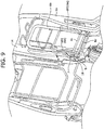
- FIG. 1 is a schematic perspective view of a seat frame
- FIG. 2 is a schematic perspective view of an armrest frame
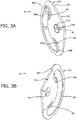
- FIG. 3A and FIG. 3B are perspective views showing a bush member
- FIG. 4 is an enlarged view of an X portion in FIG. 1
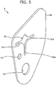
- FIG. 5 is a perspective view showing a plate member
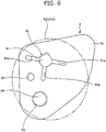
- FIG. 6 is a plan view showing the plate member
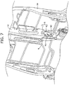
- FIG. 7 to FIG. 9 are explanatory diagrams of an assembly process of the plate member according to one embodiment of the present invention
- FIG. 10 is an explanatory diagram of incorporation of the plate member
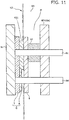
- FIG. 11 is an explanatory diagram of an A-A cross section in FIG.
- FIG. 12A and FIG. 12B are explanatory diagrams showing a relationship between a position of an armrest and a position of a moving shaft with respect to a cover portion
- FIG. 13A to FIG. 13C are explanatory diagrams showing a function of narrowed protrusions and a deformed hole.
- FIG. 3B With reference to FIG. 1 to FIG. 3A , FIG. 3B , the vehicular seat S according to the embodiment will be described.
- the vehicular seat S is a seat having a seat frame F as a framework, and when used, is in a state that a cushion pad K1 is disposed on the seat frame F and a surface thereof is covered with a skin material K2.
- a finished product is provided with a known headrest, and the headrest is formed, for example, by attaching the cushion pad K1 and the skin material K2 to a core material (not shown) of a head portion.
- a headrest pillar (not shown) for being connected to the seat back frame 1 projects.
- a reference numeral H denotes a pillar support portion which supports t headrest pillar.
- the seat frame F of the vehicular seat S is, as shown in FIG. 1 , composed of the seat back frame 1 and a seat cushion frame 2.
- the seat back frame 1 is for supporting the back of an occupant, and the cushion pad K1 and the skin material K2 are attached thereto, thereby constituting a seat back of the vehicular seat S.
- the seat cushion frame 2 is for supporting the hip of an occupant from below, and similarly, the cushion pad K1 and the skin material K2 are attached thereto, thereby constituting a seating portion of the vehicular seat S.
- a lower end of the seat back frame 1 and a rear end of the seat cushion frame 2 are connected via coupling members 3, 3, and the seat is configured in such a manner that the angle of the seat back frame 1 with respect to the seat cushion frame 2 is adjustable by a reclining mechanism 11.
- the seat back frame 1 has a frame-shaped (a frame-shape having an opening downward) member, as a basic configuration, which is composed of side frames 1a, 1a on the seat back side disposed separately in a vehicle width direction, and a substantially U-shaped upper frame 1b disposed so as to bridge upper ends of the side frames.
- a frame-shaped (a frame-shape having an opening downward) member as a basic configuration, which is composed of side frames 1a, 1a on the seat back side disposed separately in a vehicle width direction, and a substantially U-shaped upper frame 1b disposed so as to bridge upper ends of the side frames.
- the upper frame 1b is a substantially U-shaped pipe having an upward protruding portion, whose both free end portions are connected to upper end portions of the side frames 1a, 1a on the seat back side respectively, and to the upper side thereof, the pillar support portion H is welded.
- lower end portions of the side frames 1a, 1a on the seat back side are connected to the rear end side of the seat cushion frame 2 respectively via the reclining mechanism 11 and the coupling members 3, 3.
- a center frame 1c on the back side is disposed so as to be parallel thereto.
- One surface side of a lower end portion of the center frame 1c on the back side is welded to an upper end of a connecting frame 1d.
- connecting frame 1d is mounted to an upper portion on the rear end side of a center frame 2e on a cushion (described later) side via the reclining mechanism 11.
- the center frame 1c on the back side is formed into a hollow solid shape by combining two frame pieces formed into a similar shape.
- an armrest receiving member 7 constituting a guide member G is arranged on the other surface side (the surface opposite to the side where the connecting frame 1d is welded) of the lower end side of the center frame 1c on the back side.
- an armrest receiving member 7 constituting the guide member G is disposed.
- the armrest receiving members 7, 7 are disposed in opposed positions at the same height.
- each side frame 2a on the cushion side constituting the seat cushion frame 2 is a member extended in a front to back direction, and is connected to the seat back frame 1 at the rear end portion.
- the side frame 2a on the cushion side located at one end side (the left side) in a right and left direction and the side frame 2a on the cushion side located at the other end side in the right and left direction are separated in the right and left direction in a state of being parallel to each other.
- the side frames 2a, 2a on the cushion side are connected via a rear side coupling pipe 2b at the rear end side and via a front side upper portion coupling pipe 2c at the front end upper side, respectively.
- the rear side coupling pipe 2b is a pipe member extending from one end in a width direction of the vehicular seat S to the other end.
- the front side upper portion coupling pipe 2c is a pipe member formed by bending into a substantially U-shape, and both free ends thereof are connected to front end portions of the side frames 2a, 2a on the cushion side. That is, the substantially U-shaped front side upper portion coupling pipe 2c is connected to the front end portions of the side frames 2a, 2a on the cushion side at the both free ends thereof in a state where the front side upper portion coupling pipe 2c protrudes forward.
- an angular cylindrical front side lower portion coupling bar 2d is bridged.
- the rectangular frame-shaped seat cushion frame 2 is formed as a basic configuration by these side frames 2a, 2a on the cushion side, rear side coupling pipe 2b, front side upper portion coupling pipe 2c, and front side lower portion coupling bar 2d.
- the center frame 2e on the cushion side is disposed so as to be parallel thereto.
- the center frame 2e on the cushion side is fixed to the front side lower portion coupling bar 2d at the front end side thereof, the rear end side thereof is mounted to the rear side coupling pipe 2b in a state that the rear side coupling pipe 2b passes therethrough, and the upper portion thereof is mounted to the lower end portion of the connecting frame 1d via the reclining mechanism 11.
- the rail coupling member 5 is directly welded at the lower portion thereof.
- a lower frame 4 is arranged (so as to bridge the front side lower portion coupling bar 2d and the rear side coupling pipe 2b), and to the lower end side of the lower frame 4, the rail coupling member 5 is welded.
- the rail device is configured by two sets of combined bodies of an upper rail and a lower rail, and the respective combined bodies of the upper rail and the lower rail are disposed in the lower portion of the both side frames 2a, 2a on the cushion side respectively.
- both lower rails are fixed to a vehicle body floor, and the both upper rails are directly or indirectly connected to the side frames 2a, 2a on the cushion side respectively.
- FIG. 2 shows the armrest T in a stored state, and in this state, an up and down direction is defined as shown in FIG. 2 .
- the armrest T is a substantially rectangular parallelepiped shaped member configured by having an armrest frame as a framework, and when used, is in a state that the cushion pad K1 is disposed on the armrest frame 6 and a surface thereof is covered with the skin material K2.
- the armrest frame 6 has a frame-shaped (a frame-shape having an opening downward) member, as a basic configuration, which is composed of two side frames 6a, 6a on the armrest side disposed separately in a width direction, and a substantially U-shaped upper frame 6b on the armrest side disposed so as to bridge upper ends of the side frames.
- a frame-shaped (a frame-shape having an opening downward) member as a basic configuration, which is composed of two side frames 6a, 6a on the armrest side disposed separately in a width direction, and a substantially U-shaped upper frame 6b on the armrest side disposed so as to bridge upper ends of the side frames.
- the upper frame 6b on the armrest side is a substantially U-shaped pipe having an upward protruding portion, whose both free end portions are connected to upper end portions of the side frames 6a, 6a on the armrest side respectively.
- the side frame 6a located at the center frame 1c on the back side (hereinafter, referred to as “a center side frame 601 on the armrest side") is formed by bending so that a lower end portion thereof approaches to a direction of the other side frame 6a on the armrest side (hereinafter, referred to as “other side frame 602 on the armrest side”).
- the center side frame 601 on the armrest side is configured so as to extend downwardly by bending once to the other side frame 602 on the armrest side from a slight lower position than a coupling portion with the lower end of the upper frame 6b on the armrest side (that is, the portion is offset to the other side frame 602 on the armrest side), and therefore, the distance between the center frame 1c on the back side and the lower portion of the center side frame 601 on the armrest side is larger than that of the upper portion.
- a member arrangement space M1 a space between the center frame 1c on the back side and the lower portion of the center side frame 601 on the armrest side.
- a plate member 9 and a spacer 10 described later are arranged in a space between the center frame 1c on the back side and the lower portion of the center side frame 601 on the armrest side.
- the arrangement configuration will be described later in detail.
- pivot center shaft through-holes 61, 61 are respectively formed, and stopper shaft through-holes 62, 62 are similarly formed.
- the stopper shaft through-hole 62 is formed in the lower end portion of the side frame 6a on the armrest side, and the pivot center shaft through-hole 61 is formed in a slightly upper portion on the rear side than the stopper shaft through-hole 62.
- the both end portions of the pivot center shaft 6c and the stopper shaft 6d project to the outside than the side frames 6a, 6a on the armrest side, and also in a state that a cushion material and the skin material K2 are disposed, pass the skin material K2 and project to the outside.
- the armrest T is pivotably mounted between the guide members G, G (between the armrest receiving members 7, 7).
- the both projection ends of the pivot center shaft 6c and the stopper shaft 6d are rotatably supported by the guide members G, G (the armrest receiving members 7, 7) so as to be pivotable respectively.
- This configuration is a main configuration of the present embodiment, and therefore will be described later in detail.
- the guide member G is configured by having a bush member 8 and the armrest receiving member 7 described next. That is, the guide member G according to the present embodiment is configured by combining the bush member 8 and the armrest receiving member 7.
- bush members 8 are disposed on the two armrest receiving members 7 respectively, in the present example, two bush members are used.
- the bush member 8 is a substantially sector-shaped flat plate member.
- pivot center shaft through-hole 81 on the bush member side is formed.
- a slit 81a is formed toward an apical direction of the bush member 8.
- a locking pawl 81b on the center shaft through-hole side rises.
- a stopper shaft moving hole 82 on the bush member side is formed as a long hole.
- narrowed protrusions 82a, 82a are respectively formed, and in the portions of the narrowed protrusions 82a, 82a, the stopper shaft moving hole 82 on the bush member side is configured to be smaller in width thereof.
- the narrowed protrusion 82a is a substantially triangular protruding portion formed so as to protrude toward the inside of the stopper shaft moving hole 82 on the bush member side, and two protrusions are formed on one end side.
- one narrowed protrusion 82a is configured so as to protrude toward the inside of the stopper shaft moving hole 82 on the bush member side from the pivot center shaft through-hole 81 on the bush member side
- the other narrowed protrusion 82a is configured so as to protrude toward the inside of the stopper shaft moving hole 82 on the bush member side located at the opposite side
- the apex portions of the two narrowed protrusions 82a, 82a are opposed within the stopper shaft moving hole 82 on the bush member side.
- a distance t1 between the apexes of the two narrowed protrusions 82a, 82a becomes smaller than a width t2 of the other portion of the stopper shaft moving hole 82 on the bush member side.
- the width t2 of the other portion of the stopper shaft moving hole 82 on the bush member side is configured to be slightly larger than an outer diameter t3 of the stopper shaft 6d, and the distance t1 between the two narrowed protrusions 82a, 82a is configured to be smaller than the outer diameter t3 of the stopper shaft 6d.
- a space between the positions of the apexes of the two narrowed protrusions 82a, 82a and the proximate end portion is configured to be almost same as a cross section of the stopper shaft 6d, and that is, in the space, the stopper shaft 6d is configured to be locked.
- This configuration is provided on both ends of the stopper shaft moving hole 82 on the bush member side respectively.
- two sets of two narrowed protrusions 82a, 82a are provided (one set is provided on the both end sides, respectively).
- the rising direction of the locking pawls 82b, 82b on the stopper shaft through-hole side is a direction same as the rising direction of the above-mentioned locking pawl 81b on the center shaft through-hole side, and is a direction in which the armrest receiving member 7 to be mounted is arranged.
- a substantially triangular deformed hole 83 is formed.
- the deformed hole 83 is bored so that the vicinity of an apex thereof is along the shape of the narrowed protrusion 82a. That is, the deformed hole 83 is perforated so that the apex is directed to the stopper shaft moving hole 82 on the bush member side.
- the deformed hole 83 is also formed in the both end portions (two holes in total) respectively.
- the bush member 8 is not a completely flat member, and is configured so that a thickness of a portion where the stopper shaft moving hole 82 on the bush member side is perforated (which is the vicinity of the end portion on the substantially circular arc shape side, and hereinafter, is referred to as "a plate member non-abutment portion D1") is thinner than that of a portion where the pivot center shaft through-hole 81 on the bush member side and the deformed holes 83 , 83 are perforated (which is a sector portion around the pivot center shaft through-hole 81 on the bush member side and not including the stopper shaft moving hole 82 on the bush member side, and hereinafter, is referred to as "a plate member abutment portion D2"). That is, a stepped portion D3 is formed in a boundary portion between the both portions, and the thicknesses of the both portions are configured to be different.
- the plate member abutment portion D2 to which the plate member 9 described later abuts is increased in thickness and improved in rigidity, and the plate member non-abutment portion D1 is decreased in thickness from the stepped portion D3 as a boundary, therefore, the plate member 9 in face contact with the plate member abutment portion D2 can be effectually prevented from abutting the plate member non-abutment portion D1 which is a portion where the stopper shaft moving hole 82 on the bush member side is formed.
- the armrest receiving member 7 is formed with a pivot center shaft through-hole 71 on the receiving member side at the front side thereof, and along an arc shape around the pivot center shaft through-hole 71 on the receiving member side, a stopper shaft moving hole 72 on the receiving member side is formed as a long hole.
- pivot center shaft through-hole 71 on the receiving member side and stopper shaft moving hole 72 on the receiving member side are formed in the size and positional relationship similar to that of the pivot center shaft through-hole 81 on the bush member side and stopper shaft moving hole 82 on the bush member side formed in the above-mentioned bush member 8. Therefore, the bush member 8 can be overlapped with the armrest receiving member 7 in such a manner that the pivot center shaft through-hole 71 on the receiving member and the pivot center shaft through-hole 81 on the bush member side are communicated, and the stopper shaft moving hole 72 on the receiving member side and the stopper shaft moving hole 82 on the bush member side are communicated.
- the locking pawl 81b on the center shaft through-hole side is press-fitted and locked to the pivot center shaft through-hole 71 on the receiving member, and the locking pawls 82b, 82b on the stopper shaft through-hole side are press-fitted to both end portions of the stopper shaft moving hole 72 on the receiving member side and locked to an inner wall portion of the receiving wall 72b on the stopper shaft through-hole side at the both end portions, thereby the bush member 8 can be mounted to the armrest receiving member 7.
- the slit 81a and the deformed hole 83 are bent, and thereby capable of efficiently performing the mounting.
- the plate member 9 is a member which is interposed between the guide member G and the center side frame 601 on the armrest side and is for preventing foreign matter entering.
- the plate member 9 according to the present embodiment is a substantially sector-shaped flat plate member.
- a pivot center shaft through-hole 91 on the plate member side which is perforated into a substantially square shape and is corresponding to a third hole is formed.
- the length of an opening side of the pivot center shaft through-hole 91 on the plate member side is configured to be slightly smaller than an outer diameter of the pivot center shaft 6c, and therefore, the pivot center shaft 6c is press-fitted and fixed to the pivot center shaft through-hole 91 on the plate member side.
- the slits 91a on the plate member side are formed in this way, and thereby a load to the plate member 9 can be further mitigated.
- a stopper shaft through-hole 92 on the plate member side corresponding to a fourth hole is formed.
- An inner diameter of the stopper shaft through-hole 92 on the plate member side is configured to be slightly larger than the outer diameter of the stopper shaft 6d.
- an incorrect assembly prevention hole 93 is formed between the pivot center shaft through-hole 91 on the plate member side and the stopper shaft through-hole 92 on the plate member side.
- the incorrect assembly prevention hole 93 is formed so as to be located on the front side of the vehicular seat S at the time of assembly of the plate member 9.
- a work hole K21 on the skin material side which is an opening for working and is corresponding to a work hole is formed (see FIG. 6 ).
- an outer extension portion 9a a portion which is not exposed is referred to as "an outer extension portion 9a".
- the plate member 9 can be effectually prevented from falling out to the outside from the work hole K21 on the skin material side.
- the guide members G, G are configured by mounting the bush members 8, 8 to the armrest receiving members 7, 7.
- the armrest receiving member 7 is mounted by welding to the center frame 1c on the back side (the other is mounted to the side frame 1a on the seat back side) .
- this communication hole is referred to as "a first communication hole H1"
- the stopper shaft moving hole 72 on the receiving member side and the stopper shaft moving hole 82 on the bush member side are disposed to communicate (hereinafter, this communication hole is referred to as "a second communication hole H2").
- first communication hole H1 corresponds to a first hole and the second communication hole H2 corresponds to a second hole.
- the bush member 8 is thus mounted to the armrest receiving member 7, and the end portion of the pivot center shaft 6c is pivotably inserted into the first communication hole H1. Moreover, at the same time, the end portion of the stopper shaft 6d is inserted into the second communication hole H2 movably along the long hole.
- the plate member 9 is provided only on the center side frame 601 side on the armrest side which is the side arranged on the center frame 1c on the back side.
- the plate member 9 and the spacer 10 described later are not disposed, and the other side frame 602 on the armrest side and the bush member 8 are configured to be opposed directly.
- the plate member 9 is disposed so as to be stacked on the bush member 8.
- the pivot center shaft 6c is press-fitted into the pivot center shaft through-hole 91 on the plate member side, and the stopper shaft 6d is inserted into the stopper shaft through-hole 92 on the plate member side.
- the outer extension portion 9a is stacked to be disposed rearward, and by such a stacking, the incorrect assembly prevention hole 93 is located forwardly.
- the spacer 10 in a ring spring shape is disposed.
- the spacer 10 is a ring spring configured into a substantially cylindrical shape and formed with a spacer slit 10a crossing between both openings in the side surface thereof. Then, by pushing the pivot center shaft 6c into an inner hole from the spacer slit 10a, the spacer 10 is mounted to the pivot center shaft 6c. That is, in such a configuration, the pivot center shaft 6c can be held by a restoring force of the spacer slit 10a.
- the spacer 10 is mounted to the pivot center shaft 6c so as to be interposed between the plate member 9 and the center side frame 601 on the armrest side.
- the member arrangement space M1 is formed between the center frame 1c on the back side and the lower portion of the center side frame 601 on the armrest side, and therefore, the plate member 9 and the spacer 10 can be put in the member arrangement space M1.
- the motion of the armrest T will be described with reference to FIG. 12A and FIG. 12B .
- the bush member 8 is mounted to the armrest receiving member 7 as described above, and is immovable.
- FIG. 12A shows a stored state that the armrest T rises substantially perpendicular to the vehicle body floor, and at this time, the stopper shaft 6d is disposed on one end (a lower end) side of the communication hole between the stopper shaft moving hole 72 on the receiving member side and the stopper shaft moving hole 82 on the bush member side.
- the stopper shaft 6d is disposed on the other end (an upper end) side of the communication hole between the stopper shaft moving hole 72 on the receiving member side and the stopper shaft moving hole 82 on the bush member side.
- the armrest T in the present example is displaced between the stored position and the usage position, and when reaching the stored position and the usage position which are terminal points, the stopper shaft 6d is in a state of being disposed in the both respective end positions of the communication hole between the stopper shaft moving hole 72 on the receiving member side and the stopper shaft moving hole 82 on the bush member side.
- the distance t1 between the apexes of the two narrowed protrusions 82a, 82a is configured to be smaller than the width t2 of the other portion of the stopper shaft moving hole 82 on the bush member side, and similarly, the distance t1 between the apexes of the two narrowed protrusions 82a, 82a is configured to be smaller than the outer diameter t3 of the stopper shaft 6d.
- the stopper shaft 6d moves and reaches the position between the apexes of the two narrowed protrusions 82a, 82a, as shown in FIG. 13B , the stopper shaft 6d passes the position while spreading out the portion between the apexes of the two narrowed protrusions 82a, 82a.
- the deformed hole 83 is formed close to the narrowed protrusion 82a, by deformation of the deformed hole 83, the force in the white outlined arrow direction can be absorbed, and therefore the bush member 8 itself can be effectually prevented from being deformed.
- the vicinity of the opposite narrowed protrusion 82a (the outer narrowed protrusion 82a) is bent to the outside, and thereby capable of letting out the force in the white outlined arrow direction.
- the force in the white outlined arrow direction may be efficiently let out.
- the stopper shaft 6d abuts one end portion (an upper end portion) of the communication hole between the stopper shaft moving hole 72 on the receiving member side and the stopper shaft moving hole 82 on the bush member side, and the stopper shaft 6d is prohibited from further moving in the arrow direction.
- an operating force of an operator is reduced to a small force from a large force. That is, in a step of FIG. 13B , since the force for spreading out the portion between the apexes of the two narrowed protrusions 82a, 82a is required, the operating force for pivoting the armrest T needs to be increased, and in a step of FIG. 13C , contact of the stopper shaft and the both apexes of the two narrowed protrusions is released, and therefore the operating force is reduced.
- the shape of the narrowed protrusion 82a may be any shape such as a circular arc and a polygon
- the shape of the deformed hole 83 may also be any shape such as a circle and a polygon.
- stop positions are provided at the stored position and the usage position, the present invention is not limited thereto, and if necessary, the stop position and a click feeling may be imparted by similarly providing the narrowed protrusion 82a in a halfway step or the like.
Abstract
Description
- The present invention relates to a seat provided with an armrest and, more specifically, to a seat provided with an armrest which is designed so as to be capable of being deployed and stored with respect to the seat.
- In a vehicle such as an automobile, a vehicular seat on which an occupant is seated is disposed, and such a vehicular seat is often provided with an armrest.
- In order to improve the convenience of an occupant, such an armrest is sometimes capable of being displaced between a stored position and a deployed (usage) position.
- For example, in
Patent Literature 1 andPatent Literature 2, an armrest is provided in a central portion of a rear seat. - These armrests are configured so as to be capable of being displaced between a stored position where the armrest is stored along a seat back (that is, it is disposed so as to rise in an up and down direction) and a usage (deployed) position where the armrest is deployed in a position substantially perpendicular to the seat back.
- This displacement is performed by pivoting the armrest around an one end (which is a lower end side at the time of storage and is a rear end side at the time of deployment) of the armrest as a fulcrum.
- That is, the one end side (which is the lower end side at the time of storage and is the rear end side at the time of deployment) of the armrest is rotatably supported so as to be pivotable with respect to the seat back, and a free end side (which is an upper end side at the time of storage and is a front end side at the time of deployment) is pivoted drawing a circular arcuate locus around the one end side, thereby being displaced between the stored position and the usage (deployed) position.
- Then, in the seat back, a recessed portion in which the armrest can be stored at the time of storage of the armrest is formed, or a gap between the rear seats divided into two parts serves as a storage space of the armrest.
-
- PATENT LITERATURE: 1:
JP 2002-306275 - PATENT LITERATURE 2:
JP 2008-049755 - As thus described, although the armrest which is formed so as to be capable of being displaced between the stored position and the usage (deployed) position is used for the vehicular seat, the armrest is configured so as to be pivoted about the one end side as a pivot center, and therefore there was a possibility that foreign matter enters the interior in the vicinity of the pivot portion.
- That is, in the vicinity of the pivot center, a pivot shaft, a bearing member and the like are disposed, but there is a possibility that foreign matter enters the vicinity of these members from a small gap formed between a side surface of the armrest and a side wall of a storage portion, thus a technique for preventing this possibility has been demanded.
- Moreover, a technique for which a time point when displacement between the stored position and the usage (deployed) position is completely finished is recognizable by an operational feeling is demanded at the same time.
- An object of the present invention is to solve the above problems and provide, in an armrest capable of being displaced between a stored position and a deployed position, a seat provided with an armrest capable of preventing foreign matter from entering the interior thereof through a gap formed between the armrest (in particular, the vicinity of the center of displacement thereof) and a mounted portion.
- Moreover, another object of the present invention is to provide, in an armrest capable of being displaced between a stored position and a deployed position, a seat provided with an armrest for which a displacement completion point to each position is recognizable.
- In accordance with a seat provided with an armrest according to the present invention, the above problems are solved by a seat provided with an armrest which is pivotally displaced around one end side between a stored position where it is retracted in a posture along a seat back and a deployed position where it is deployed to a position where a free end side projects forwardly from the seat back, in which: on the one end side of the armrest, a first shaft serving a pivot center is disposed so as to pass through in a width direction of the seat, and a second shaft passes through the one end side substantially parallel to the first shaft; the first shaft is pivotably supported by a first hole formed in a guide member fixed to a seat back frame which is a framework of the seat back, and the second shaft is inserted into a long hole-shaped second hole formed along a partial circular arc locus around the first hole so as to be movable along the second hole; and between a side surface side of the armrest and the guide member, a plate member which covers at least a part of the second hole is provided.
- As thus described, in the present invention, in order to pivotably mount the armrest, the first shaft and the second shaft are projected from one end of the armrest, and these projection ends are rotatably supported on a skeleton side (which is the guide member fixed to the seat back frame, in the present invention).
- Then, the armrest pivots around this pivot center shaft, and by such a configuration, a gap is formed between the guide member and the side surface of the armrest.
- However, in the present invention, the plate member is interposed between the guide member and the side surface of the armrest, the second hole portion through which the second shaft passes is covered, and foreign matter can be effectually prevented from entering through the gap between the guide member and the side surface of the armrest.
- In addition, the second shaft is moved in the second hole which is a long hole in a shape along the partial circular arc locus.
- That is, both end portions of the second hole which is the long hole become regulating points of movement, and thereby capable of defining a range that the armrest pivots. In other words, by aligning one end portion of the second hole to the stored position and aligning the other end portion thereof to the deployed position, the armrest can be prohibited from pivoting (overturning) beyond the stored position and the deployed position, and therefore, by preventing foreign matter from entering that portion, the operation of the armrest can be effectually prevented from being inhibited due to foreign matter which becomes an obstacle, and the operation of the armrest can be more accurately performed.
- At this time, if at least a part of the guide member and at least a part of the plate member are brought into face contact, a function of covering the second hole portion through which the second shaft passes is enhanced, and foreign matter entering can be more effectually prevented.
- Further, at this time, concretely, if the first shaft and the second shaft pass through the plate member and are fixed, it is preferable because the plate member can be disposed on the armrest side with a simple configuration.
- Moreover, it is preferable if a third hole and a fourth hole are formed in the plate member, one of the first shaft and the second shaft is press-fitted and fixed to the third hole, and the other of the first shaft and the second shaft passes through the fourth hole perforated so as to have a larger diameter than a shaft outer diameter of the other.
- By such a configuration, a gap corresponding to a dimensional difference is formed between the hole having a larger diameter and the shaft passing through the hole. Hence, it is preferable because an assembly error of the plate member can be absorbed by the gap.
- Further, it is preferable if the one of the first shaft and the second shaft is press-fitted into the third hole bored into a substantially square shape which is configured by a side length smaller than a shaft outer diameter of the one.
- By such a configuration, press fitting is easy because the shaft (the first shaft or the second shaft) of circular cross section is press-fitted into the substantially square-shaped third hole. Moreover, in a cross section of a press-fit portion, the circular shaft (the first shaft or the second shaft) is in a state of internally contacting the substantially square-shaped hole, and therefore a void is formed between the substantially square-shaped hole and the circular shaft (the first shaft or the second shaft) (in the vicinity of apexes of the substantially square shape). By this void, a load to the plate member due to the press-fitted shaft (the first shaft or the second shaft) is mitigated.
- Moreover, at this time, if a slit extending in an outside direction is formed continuously to the third hole, it is preferable because a load to the plate member due to the press-fitted shaft (the first shaft or the second shaft) is mitigated.
- Further, at this time, it is preferable if, in the guide member, a thickness of a peripheral portion of the first hole is formed thicker than a thickness of a peripheral portion of the second hole.
- By such a configuration, since the thickness in the vicinity of the first hole which is a first shaft arrangement portion serving a pivot center is increased, rigidity in the vicinity of the pivot center is enhanced.
- Moreover, at this time, it is preferable if, in the guide member, the peripheral portion of the first hole is brought into face contact with the plate member, and the peripheral portion of the second hole and at least a part of the plate member are opposed via a gap.
- By such a configuration, in the vicinity of the second shaft moving in the second hole which is the long hole, a gap is formed between the second shaft and the plate member, and therefore a load to the second shaft is mitigated.
- Therefore, a load to the plate member in which the second shaft is inserted is mitigated, and durability of the plate member is improved.
- Moreover, at this time, it is preferable if, between the plate member and an armrest frame which is a framework of the armrest, a spacer member is interposed. By such a configuration, the gap between the plate member and the armrest frame can be filled. Hence, the plate member can be more efficiently pushed to the guide member, and as a result, the plate member can be effectively brought into face contact with the guide member.
- Moreover, at this time, it is preferable if the armrest is configured by having two side frames on the armrest side which are disposed separately in the width direction of the seat, and an upper frame on the armrest side which bridges upper ends of the two side frames on the armrest side; and at least a part of the side frame on the armrest side located at the side where the plate member is provided is arranged to be offset to the arrangement direction of the side frame on the armrest side located at the side where the plate member is not provided.
- By such a configuration, since, corresponding to an amount of offset, a gap is formed between the side frames on the armrest side and the guide member, assembling of members such as the plate member and a spacer is facilitated.
- It should be noted that "at least a part" is preferably envisaged to be a portion opposed to the guide member.
- Further, at this time, it is preferable if the armrest is configured by having the armrest frame, a pad provided peripherally in the armrest frame, and a skin material which covers the pad; in the skin material, a work hole which opens so as to expose a periphery of the first shaft is formed; and the plate is provided with an outer extension portion which extends in an outside direction than the work hole.
- By such a configuration, working is facilitated by the work hole, and the plate member can be effectually prevented from falling out to the outside from the work hole because of the outer extension portion serving an obstacle.
- Moreover, in the present invention, the armrest is concretely preferably used if provided on the inside of the seat back frame.
- Further, in a concrete application of the present invention, the seat is used for a seat whose width direction is larger of a semi-bench seat, and the plate is preferably used if provided on the inside in the width direction of the seat.
- According to the present invention, the plate member is interposed between the guide member and the side surface of the armrest, the second hole portion which is the long hole through which the second shaft (which is a moving shaft, and is a stopper shaft) passes is covered, and therefore foreign matter can be effectually prevented from entering the second hole through the gap.
- In the present invention, the above covering function is more enhanced, and foreign matter entering can be more effectually prevented.
- According to present invention, the plate member can be disposed on the armrest side with a simple configuration, and workability is improved.
- According to the present invention, an assembly error of the plate member can be absorbed.
- According to the present invention, a load to the plate member can be mitigated.
- According to the present invention, rigidity in the vicinity of the pivot center is enhanced.
- According to the invention, durability of the plate member is improved.
- According to the present invention, the plate member can be more efficiently brought into face contact with the guide member.
- According to the present invention, assembling of each member into the gap formed by offset is facilitated.
- According to present invention, workability is improved, and the plate member can be effectually prevented from falling out to the exterior from the work hole.
- By applying the present invention, it is possible to provide a concretely satisfactory use mode.
-
-
FIG. 1 is a schematic perspective view of a seat frame according to one embodiment of the present invention. -
FIG. 2 is a schematic perspective view of an armrest frame according to one embodiment of the present invention. -
FIG. 3A is a perspective view showing a bush member according to one embodiment of the present invention. -
FIG. 3B is a perspective view showing the bush member according to one embodiment of the present invention. -
FIG. 4 is an enlarged view of an X portion inFIG. 1 . -
FIG. 5 is a perspective view showing a plate member according to one embodiment of the present invention. -
FIG. 6 is a plan view showing the plate member according to one embodiment of the present invention. -
FIG. 7 is an explanatory diagram of an assembly process of the plate member according to one embodiment of the present invention. -
FIG. 8 is an explanatory diagram of an assembly process of the plate member according to one embodiment of the present invention. -
FIG. 9 is an explanatory diagram of an assembly process of the plate member according to one embodiment of the present invention. -
FIG. 10 is an explanatory diagram of incorporation of the plate member according to one embodiment of the present invention. -
FIG. 11 is an explanatory diagram of an A-A cross section inFIG. 9 . -
FIG. 12A is an explanatory diagram showing a relationship between a position of an armrest and a position of a moving shaft with respect to a cover portion according to one embodiment of the present invention. -
FIG. 12B is an explanatory diagram showing a relationship between a position of the armrest and a position of the moving shaft with respect to the cover portion according to one embodiment of the present invention. -
FIG. 13A is an explanatory diagram showing a function of narrowed protrusions and a deformed hole according to one embodiment of the present invention. -
FIG. 13B is an explanatory diagram showing a function of the narrowed protrusions and the deformed hole according to one embodiment of the present invention. -
FIG. 13C is an explanatory diagram showing a function of the narrowed protrusions and the deformed hole according to one embodiment of the present invention. - Hereinafter, one embodiment of the present invention will be described with reference to the drawings. It should be noted that members, arrangements and the like described below do not limit the present invention, and, of course, can be variously modified in accordance with the purport of the present invention. Moreover, in the present specification, a vehicle is intended to refer to a moving vehicle on which a seat can be mounted, including a ground traveling vehicle having wheels such as an automobile and a train, an aircraft and a ship moving on the place other than the ground, and the like.
- Moreover, a right and left direction means a right and left direction in a state directed to a front of a vehicle, and is a direction corresponding to a width direction of a seat back
frame 1 and aseat cushion frame 2 described later. Moreover, a front to back direction means a front to back direction in a state that an occupant is seated. -
FIG. 1 to FIG. 13A ,FIG. 13B, and FIG. 13C are related to one embodiment of the present invention,FIG. 1 is a schematic perspective view of a seat frame,FIG. 2 is a schematic perspective view of an armrest frame,FIG. 3A and FIG. 3B are perspective views showing a bush member,FIG. 4 is an enlarged view of an X portion inFIG. 1 ,FIG. 5 is a perspective view showing a plate member,FIG. 6 is a plan view showing the plate member,FIG. 7 to FIG. 9 are explanatory diagrams of an assembly process of the plate member according to one embodiment of the present invention,FIG. 10 is an explanatory diagram of incorporation of the plate member,FIG. 11 is an explanatory diagram of an A-A cross section inFIG. 9 ,FIG. 12A and FIG. 12B are explanatory diagrams showing a relationship between a position of an armrest and a position of a moving shaft with respect to a cover portion, andFIG. 13A to FIG. 13C are explanatory diagrams showing a function of narrowed protrusions and a deformed hole. - Hereinafter, an example in which a seat according to the present invention is applied to a vehicular seat is shown.
- Then, in the present embodiment, an example in which the seat is applied to a seat referred to as a so-called "semi-bench seat" of such a vehicular seat is shown, and more specifically, an example in which a seat whose width direction is larger of the semi-bench seat is applied as a vehicular seat S is described.
- With reference to
FIG. 1 to FIG. 3A ,FIG. 3B , the vehicular seat S according to the embodiment will be described. - As shown in
FIG. 1 , the vehicular seat S is a seat having a seat frame F as a framework, and when used, is in a state that a cushion pad K1 is disposed on the seat frame F and a surface thereof is covered with a skin material K2. - In addition, although illustration is omitted, a finished product is provided with a known headrest, and the headrest is formed, for example, by attaching the cushion pad K1 and the skin material K2 to a core material (not shown) of a head portion. Moreover, from the lower side, a headrest pillar (not shown) for being connected to the seat back
frame 1 projects. It should be noted that a reference numeral H denotes a pillar support portion which supports t headrest pillar. - The seat frame F of the vehicular seat S is, as shown in
FIG. 1 , composed of the seat backframe 1 and aseat cushion frame 2. - The seat back
frame 1 is for supporting the back of an occupant, and the cushion pad K1 and the skin material K2 are attached thereto, thereby constituting a seat back of the vehicular seat S. - Moreover, the
seat cushion frame 2 is for supporting the hip of an occupant from below, and similarly, the cushion pad K1 and the skin material K2 are attached thereto, thereby constituting a seating portion of the vehicular seat S. - Then, a lower end of the seat back
frame 1 and a rear end of theseat cushion frame 2 are connected viacoupling members frame 1 with respect to theseat cushion frame 2 is adjustable by areclining mechanism 11. - As shown in
FIG. 1 , the seat backframe 1 has a frame-shaped (a frame-shape having an opening downward) member, as a basic configuration, which is composed ofside frames upper frame 1b disposed so as to bridge upper ends of the side frames. - The
upper frame 1b is a substantially U-shaped pipe having an upward protruding portion, whose both free end portions are connected to upper end portions of theside frames - Moreover, lower end portions of the
side frames seat cushion frame 2 respectively via thereclining mechanism 11 and thecoupling members - Moreover, between the
side frames center frame 1c on the back side is disposed so as to be parallel thereto. - One surface side of a lower end portion of the
center frame 1c on the back side is welded to an upper end of a connectingframe 1d. - In addition, the connecting
frame 1d is mounted to an upper portion on the rear end side of acenter frame 2e on a cushion (described later) side via thereclining mechanism 11. - In addition, in the present example, the
center frame 1c on the back side is formed into a hollow solid shape by combining two frame pieces formed into a similar shape. - Moreover, on the other surface side (the surface opposite to the side where the connecting
frame 1d is welded) of the lower end side of thecenter frame 1c on the back side, anarmrest receiving member 7 constituting a guide member G is arranged. - Moreover, of the two
side frames side frame 1a on the seat back side located at the side opposed to the other surface side (the surface opposite to the side where the connectingframe 1d is welded) of the lower end side of thecenter frame 1c on the back side, anarmrest receiving member 7 constituting the guide member G is disposed. - That is, the
armrest receiving members - In addition, a detailed configuration and a function of the guide member G provided with the
armrest receiving members - As shown in
FIG. 1 , eachside frame 2a on the cushion side constituting theseat cushion frame 2 is a member extended in a front to back direction, and is connected to the seat backframe 1 at the rear end portion. - Moreover, the
side frame 2a on the cushion side located at one end side (the left side) in a right and left direction and theside frame 2a on the cushion side located at the other end side in the right and left direction are separated in the right and left direction in a state of being parallel to each other. The side frames 2a, 2a on the cushion side are connected via a rearside coupling pipe 2b at the rear end side and via a front side upperportion coupling pipe 2c at the front end upper side, respectively. - The rear
side coupling pipe 2b is a pipe member extending from one end in a width direction of the vehicular seat S to the other end. - Moreover, the front side upper
portion coupling pipe 2c is a pipe member formed by bending into a substantially U-shape, and both free ends thereof are connected to front end portions of theside frames portion coupling pipe 2c is connected to the front end portions of theside frames portion coupling pipe 2c protrudes forward. - Moreover, on the front end lower side of the
side frames portion coupling bar 2d is bridged. - In this way, the rectangular frame-shaped
seat cushion frame 2 is formed as a basic configuration by theseside frames side coupling pipe 2b, front side upperportion coupling pipe 2c, and front side lowerportion coupling bar 2d. - Moreover, between the two
side frames center frame 2e on the cushion side is disposed so as to be parallel thereto. - The
center frame 2e on the cushion side is fixed to the front side lowerportion coupling bar 2d at the front end side thereof, the rear end side thereof is mounted to the rearside coupling pipe 2b in a state that the rearside coupling pipe 2b passes therethrough, and the upper portion thereof is mounted to the lower end portion of the connectingframe 1d via thereclining mechanism 11. - Moreover, in the lower portion of the
side frames rail coupling members - To one
side frame 2a on the cushion side, therail coupling member 5 is directly welded at the lower portion thereof. - On the inside of the
other side frame 2a on the cushion side, alower frame 4 is arranged (so as to bridge the front side lowerportion coupling bar 2d and the rearside coupling pipe 2b), and to the lower end side of thelower frame 4, therail coupling member 5 is welded. - In addition, although illustration is omitted, in the lower portion of the
seat cushion frame 2, a known rail device is provided. As with a known configuration, the rail device is configured by two sets of combined bodies of an upper rail and a lower rail, and the respective combined bodies of the upper rail and the lower rail are disposed in the lower portion of the bothside frames - Then, the both lower rails are fixed to a vehicle body floor, and the both upper rails are directly or indirectly connected to the
side frames - Next, with reference to
FIG. 2 , an armrest T according to the present embodiment will be described. - It should be noted that
FIG. 2 shows the armrest T in a stored state, and in this state, an up and down direction is defined as shown inFIG. 2 . - The armrest T is a substantially rectangular parallelepiped shaped member configured by having an armrest frame as a framework, and when used, is in a state that the cushion pad K1 is disposed on the armrest frame 6 and a surface thereof is covered with the skin material K2.
- The armrest frame 6 has a frame-shaped (a frame-shape having an opening downward) member, as a basic configuration, which is composed of two
side frames upper frame 6b on the armrest side disposed so as to bridge upper ends of the side frames. - The
upper frame 6b on the armrest side is a substantially U-shaped pipe having an upward protruding portion, whose both free end portions are connected to upper end portions of theside frames - In addition, of the
side frames side frame 6a located at thecenter frame 1c on the back side (hereinafter, referred to as "acenter side frame 601 on the armrest side") is formed by bending so that a lower end portion thereof approaches to a direction of theother side frame 6a on the armrest side (hereinafter, referred to as "other side frame 602 on the armrest side"). - That is, the
center side frame 601 on the armrest side is configured so as to extend downwardly by bending once to theother side frame 602 on the armrest side from a slight lower position than a coupling portion with the lower end of theupper frame 6b on the armrest side (that is, the portion is offset to theother side frame 602 on the armrest side), and therefore, the distance between thecenter frame 1c on the back side and the lower portion of thecenter side frame 601 on the armrest side is larger than that of the upper portion. In a space between thecenter frame 1c on the back side and the lower portion of thecenter side frame 601 on the armrest side (hereinafter, referred to as "a member arrangement space M1") aplate member 9 and aspacer 10 described later are arranged. The arrangement configuration will be described later in detail. - Further, in the lower end portions of the
side frames holes holes - The stopper shaft through-
hole 62 is formed in the lower end portion of theside frame 6a on the armrest side, and the pivot center shaft through-hole 61 is formed in a slightly upper portion on the rear side than the stopper shaft through-hole 62. - Then, between the both pivot center shaft through-
holes pivot center shaft 6c which is a round bar- shaped member passes, and between the both stopper shaft through-holes stopper shaft 6d which is a round bar-shaped member passes. - The both end portions of these
pivot center shaft 6c andstopper shaft 6d pass through the both pivot center shaft through-holes holes - That is, the both end portions of the
pivot center shaft 6c and thestopper shaft 6d project to the outside than theside frames - The armrest T is pivotably mounted between the guide members G, G (between the
armrest receiving members 7, 7). - That is, the both projection ends of the
pivot center shaft 6c and thestopper shaft 6d are rotatably supported by the guide members G, G (thearmrest receiving members 7, 7) so as to be pivotable respectively. - This configuration is a main configuration of the present embodiment, and therefore will be described later in detail.
- The guide member G is configured by having a
bush member 8 and thearmrest receiving member 7 described next. That is, the guide member G according to the present embodiment is configured by combining thebush member 8 and thearmrest receiving member 7. - Firstly, with reference to
FIG. 3A and FIG. 3B , thebush member 8 will be described. - It should be noted that, since the
bush members 8 are disposed on the twoarmrest receiving members 7 respectively, in the present example, two bush members are used. - The
bush member 8 is a substantially sector-shaped flat plate member. - In the vicinity of the center of the substantially sector, pivot center shaft through-
hole 81 on the bush member side is formed. - Then, from the pivot center shaft through-
hole 81 on the bush member side, aslit 81a is formed toward an apical direction of thebush member 8. - Moreover, from a periphery of the pivot center shaft through-
hole 81 on the bush member side, a lockingpawl 81b on the center shaft through-hole side rises. - Moreover, along an arc shape around the pivot center shaft through-
hole 81 on the bush member side, a stoppershaft moving hole 82 on the bush member side is formed as a long hole. - On both end sides of the stopper
shaft moving hole 82 on the bush member side, narrowedprotrusions protrusions shaft moving hole 82 on the bush member side is configured to be smaller in width thereof. - The narrowed
protrusion 82a is a substantially triangular protruding portion formed so as to protrude toward the inside of the stoppershaft moving hole 82 on the bush member side, and two protrusions are formed on one end side. - That is, one narrowed
protrusion 82a is configured so as to protrude toward the inside of the stoppershaft moving hole 82 on the bush member side from the pivot center shaft through-hole 81 on the bush member side, the other narrowedprotrusion 82a is configured so as to protrude toward the inside of the stoppershaft moving hole 82 on the bush member side located at the opposite side, and the apex portions of the two narrowedprotrusions shaft moving hole 82 on the bush member side. - By such a configuration, a distance t1 between the apexes of the two narrowed
protrusions shaft moving hole 82 on the bush member side. - Then, the width t2 of the other portion of the stopper
shaft moving hole 82 on the bush member side is configured to be slightly larger than an outer diameter t3 of thestopper shaft 6d, and the distance t1 between the two narrowedprotrusions stopper shaft 6d. Then, a space between the positions of the apexes of the two narrowedprotrusions stopper shaft 6d, and that is, in the space, thestopper shaft 6d is configured to be locked. - This configuration is provided on both ends of the stopper
shaft moving hole 82 on the bush member side respectively. - That is, in the present example, two sets of two narrowed
protrusions - Moreover, from the peripheries of the both end portions of the stopper
shaft moving hole 82 on the bush member side, lockingpawls - The rising direction of the locking
pawls locking pawl 81b on the center shaft through-hole side, and is a direction in which thearmrest receiving member 7 to be mounted is arranged. - Moreover, of the narrowed
protrusion 82a formed on the pivot center shaft through-hole 81 side on the bush member side, in the pivot center shaft through-hole 81 side on the bush member side, a substantially triangulardeformed hole 83 is formed. - The
deformed hole 83 is bored so that the vicinity of an apex thereof is along the shape of the narrowedprotrusion 82a. That is, thedeformed hole 83 is perforated so that the apex is directed to the stoppershaft moving hole 82 on the bush member side. - In addition, in the present example, the
deformed hole 83 is also formed in the both end portions (two holes in total) respectively. - Moreover, the
bush member 8 is not a completely flat member, and is configured so that a thickness of a portion where the stoppershaft moving hole 82 on the bush member side is perforated (which is the vicinity of the end portion on the substantially circular arc shape side, and hereinafter, is referred to as "a plate member non-abutment portion D1") is thinner than that of a portion where the pivot center shaft through-hole 81 on the bush member side and thedeformed holes hole 81 on the bush member side and not including the stoppershaft moving hole 82 on the bush member side, and hereinafter, is referred to as "a plate member abutment portion D2"). That is, a stepped portion D3 is formed in a boundary portion between the both portions, and the thicknesses of the both portions are configured to be different. - Thereby, the plate member abutment portion D2 to which the
plate member 9 described later abuts is increased in thickness and improved in rigidity, and the plate member non-abutment portion D1 is decreased in thickness from the stepped portion D3 as a boundary, therefore, theplate member 9 in face contact with the plate member abutment portion D2 can be effectually prevented from abutting the plate member non-abutment portion D1 which is a portion where the stoppershaft moving hole 82 on the bush member side is formed. - Next, with reference to
FIG. 4 , thearmrest receiving member 7 will be described. - As mentioned above, although the two
armrest receiving members 7 exist, only one of them will be described because they have a similar configuration. - The
armrest receiving member 7 is formed with a pivot center shaft through-hole 71 on the receiving member side at the front side thereof, and along an arc shape around the pivot center shaft through-hole 71 on the receiving member side, a stoppershaft moving hole 72 on the receiving member side is formed as a long hole. - Then, from a periphery of the stopper
shaft moving hole 72 on the receiving member side, a receivingwall 72b on the stopper shaft through-hole side rises (seeFIG. 10 ). - These pivot center shaft through-
hole 71 on the receiving member side and stoppershaft moving hole 72 on the receiving member side are formed in the size and positional relationship similar to that of the pivot center shaft through-hole 81 on the bush member side and stoppershaft moving hole 82 on the bush member side formed in the above-mentionedbush member 8. Therefore, thebush member 8 can be overlapped with thearmrest receiving member 7 in such a manner that the pivot center shaft through-hole 71 on the receiving member and the pivot center shaft through-hole 81 on the bush member side are communicated, and the stoppershaft moving hole 72 on the receiving member side and the stoppershaft moving hole 82 on the bush member side are communicated. - Then, when overlapping the
bush member 8 with thearmrest receiving member 7, the lockingpawl 81b on the center shaft through-hole side is press-fitted and locked to the pivot center shaft through-hole 71 on the receiving member, and the lockingpawls shaft moving hole 72 on the receiving member side and locked to an inner wall portion of the receivingwall 72b on the stopper shaft through-hole side at the both end portions, thereby thebush member 8 can be mounted to thearmrest receiving member 7. - At the time of mounting of the bush member, the
slit 81a and thedeformed hole 83 are bent, and thereby capable of efficiently performing the mounting. - With reference to
FIG. 5 andFIG. 6 , theplate member 9 according to the present embodiment will be described. - The
plate member 9 is a member which is interposed between the guide member G and thecenter side frame 601 on the armrest side and is for preventing foreign matter entering. - The
plate member 9 according to the present embodiment is a substantially sector-shaped flat plate member. - In the vicinity of the substantially sector, a pivot center shaft through-
hole 91 on the plate member side which is perforated into a substantially square shape and is corresponding to a third hole is formed. - The length of an opening side of the pivot center shaft through-
hole 91 on the plate member side is configured to be slightly smaller than an outer diameter of thepivot center shaft 6c, and therefore, thepivot center shaft 6c is press-fitted and fixed to the pivot center shaft through-hole 91 on the plate member side. - Thus, the reason why the pivot center shaft through-
hole 91 on the plate member side is formed into a substantially square shape will be described. - As shown in
FIG. 6 , when thepivot center shaft 6c is press-fitted into the pivot center shaft through-hole 91 on the plate member side in the substantially square shape having a side slightly smaller than the outer diameter of thepivot center shaft 6c, thepivot center shaft 6c pressure-contacts each side of the pivot center shaft throughhole 91 on the plate member side, but a gap is formed in the apex portions of the square shape because a circular shape internally contacts the square shape. Hence, it is possible to mitigate a load to theplate member 9 due to thepivot center shaft 6c because this gap is formed. - Then, from three apex portions of the pivot center shaft through-
hole 91 on the plate member side, threeslits 91a on the plate member side are formed so as to extend radially respectively. - The
slits 91a on the plate member side are formed in this way, and thereby a load to theplate member 9 can be further mitigated. - Moreover, in the
plate member 9, in the vicinity of a partial substantially circular arc-shaped end portion and in a position corresponding to a front side of the vehicular seat S, a stopper shaft through-hole 92 on the plate member side corresponding to a fourth hole is formed. - An inner diameter of the stopper shaft through-
hole 92 on the plate member side is configured to be slightly larger than the outer diameter of thestopper shaft 6d. By such a configuration, it is possible to absorb an assembly error. - Moreover, between the pivot center shaft through-
hole 91 on the plate member side and the stopper shaft through-hole 92 on the plate member side, an incorrectassembly prevention hole 93 is formed. - In addition, the incorrect
assembly prevention hole 93 is formed so as to be located on the front side of the vehicular seat S at the time of assembly of theplate member 9. - Moreover, in the skin material K2, a work hole K21 on the skin material side which is an opening for working and is corresponding to a work hole is formed (see
FIG. 6 ). - Then, in the
plate member 9, the vicinity of the partial substantially circular arc shaped rear end portion of the vehicular seat S is configured not to be exposed to the outside from the work hole K 21 on the skin material side, and a portion which is not exposed is referred to as "anouter extension portion 9a". - As thus described, since the
outer extension portion 9a is configured not to be exposed from the work hole K21 on the skin material side, theplate member 9 can be effectually prevented from falling out to the outside from the work hole K21 on the skin material side. - With reference to
FIG. 4 , andFIG. 7 toFIG. 11 , a mounted state of the armrest T will be described. - Firstly, as mentioned above, the guide members G, G are configured by mounting the
bush members armrest receiving members - It should be noted that since the guide members G, G have a similar configuration, only one of them will be described.
- Firstly, as shown in
FIG. 4 , thearmrest receiving member 7 is mounted by welding to thecenter frame 1c on the back side (the other is mounted to theside frame 1a on the seat back side) . - Then, as shown in
FIG. 11 , thebush member 8 is assembled to thearmrest receiving member 7. - At this time, the pivot center shaft through-
hole 71 on the receiving member side and the pivot center shaft through-hole 81 on the bush member side are disposed so as to communicate (hereinafter, this communication hole is referred to as "a first communication hole H1"), and the stoppershaft moving hole 72 on the receiving member side and the stoppershaft moving hole 82 on the bush member side are disposed to communicate (hereinafter, this communication hole is referred to as "a second communication hole H2"). - It should be noted that the first communication hole H1 corresponds to a first hole and the second communication hole H2 corresponds to a second hole.
- The
bush member 8 is thus mounted to thearmrest receiving member 7, and the end portion of thepivot center shaft 6c is pivotably inserted into the first communication hole H1. Moreover, at the same time, the end portion of thestopper shaft 6d is inserted into the second communication hole H2 movably along the long hole. - Next, a position of the
plate member 9 will be described. - Of the
side frames plate member 9 is provided only on thecenter side frame 601 side on the armrest side which is the side arranged on thecenter frame 1c on the back side. On theother side frame 602, theplate member 9 and thespacer 10 described later are not disposed, and theother side frame 602 on the armrest side and thebush member 8 are configured to be opposed directly. - As shown in
FIG. 7 ,FIG. 10 , andFIG. 11 , theplate member 9 is disposed so as to be stacked on thebush member 8. - At this time, the
pivot center shaft 6c is press-fitted into the pivot center shaft through-hole 91 on the plate member side, and thestopper shaft 6d is inserted into the stopper shaft through-hole 92 on the plate member side. - In addition, in an initial state shown in
FIG. 7 (in a state that the armrest T is in a position in the stored state), theouter extension portion 9a is stacked to be disposed rearward, and by such a stacking, the incorrectassembly prevention hole 93 is located forwardly. - Moreover, in the present embodiment, the
spacer 10 in a ring spring shape is disposed. - The
spacer 10 is a ring spring configured into a substantially cylindrical shape and formed with aspacer slit 10a crossing between both openings in the side surface thereof. Then, by pushing thepivot center shaft 6c into an inner hole from thespacer slit 10a, thespacer 10 is mounted to thepivot center shaft 6c. That is, in such a configuration, thepivot center shaft 6c can be held by a restoring force of thespacer slit 10a. - Then, as shown in
FIG, 8 to FIG. 11 , thespacer 10 is mounted to thepivot center shaft 6c so as to be interposed between theplate member 9 and thecenter side frame 601 on the armrest side. - In addition, at this time, as mentioned above, since the lower portion of the
center side frame 601 on the armrest side is offset to theother side frame 602 on the armrest side, the member arrangement space M1 is formed between thecenter frame 1c on the back side and the lower portion of thecenter side frame 601 on the armrest side, and therefore, theplate member 9 and thespacer 10 can be put in the member arrangement space M1. - The motion of the armrest T will be described with reference to
FIG. 12A and FIG. 12B . - It should be noted that, hereinafter, the description is according to the relevance between the guide member G and the armrest T, and the
plate member 9 and thespacer 10 are only led to rotate in association with the pivot and the displacement of thepivot center shaft 6c and thestopper shaft 6d, and therefore, illustration of theplate member 9 and thespacer 10 is omitted. - The
bush member 8 is mounted to thearmrest receiving member 7 as described above, and is immovable. -
FIG. 12A shows a stored state that the armrest T rises substantially perpendicular to the vehicle body floor, and at this time, thestopper shaft 6d is disposed on one end (a lower end) side of the communication hole between the stoppershaft moving hole 72 on the receiving member side and the stoppershaft moving hole 82 on the bush member side. - In this state, when the armrest T is pivoted (laid) to the arrow direction, the position of the
pivot center shaft 6c is immovable, but thestopper shaft 6d is moved in the arrow direction within the communication hole between the stoppershaft moving hole 72 on the receiving member side and the stoppershaft moving hole 82 on the bush member side. - « About Displacement of Armrest between Stored Position and Usage Position »
- Then, in a state that the armrest T is deployed to a usage position shown in
FIG. 12B , thestopper shaft 6d is disposed on the other end (an upper end) side of the communication hole between the stoppershaft moving hole 72 on the receiving member side and the stoppershaft moving hole 82 on the bush member side. - In addition, since, in both end positions of the communication hole between the stopper
shaft moving hole 72 on the receiving member side and the stoppershaft moving hole 82 on the bush member side, thestopper shaft 6d cannot move further, the both end positions become the stored position and a usage position, and further pivot of the armrest T is prohibited. - Next, with reference to
FIG. 13A to FIG. 13C , a stopper function and a recognition mechanism of a displacement completion point will be described. - As described above, the armrest T in the present example is displaced between the stored position and the usage position, and when reaching the stored position and the usage position which are terminal points, the
stopper shaft 6d is in a state of being disposed in the both respective end positions of the communication hole between the stoppershaft moving hole 72 on the receiving member side and the stoppershaft moving hole 82 on the bush member side. - In this way, when the
stopper shaft 6d reaches the both end positions of the communication hole between the stoppershaft moving hole 72 on the receiving member side and the stoppershaft moving hole 82 on the bush member side, in the present example, a mechanism for recognizing that those positions are pivot completion points exists. - As described above, the distance t1 between the apexes of the two narrowed
protrusions shaft moving hole 82 on the bush member side, and similarly, the distance t1 between the apexes of the two narrowedprotrusions stopper shaft 6d. - Therefore, when the
stopper shaft 6d moves and reaches the position between the apexes of the two narrowedprotrusions FIG. 13B , thestopper shaft 6d passes the position while spreading out the portion between the apexes of the two narrowedprotrusions - That is, at this time, a force is applied to a direction shown by the white outlined arrow direction spreading out the portion between the apexes of the two narrowed
protrusions - In addition, at this time, in the present example, since the
deformed hole 83 is formed close to the narrowedprotrusion 82a, by deformation of thedeformed hole 83, the force in the white outlined arrow direction can be absorbed, and therefore thebush member 8 itself can be effectually prevented from being deformed. - Moreover, the vicinity of the opposite narrowed
protrusion 82a (the outer narrowedprotrusion 82a) is bent to the outside, and thereby capable of letting out the force in the white outlined arrow direction. In addition, by forming a notch portion protruded to the inside in that position, the force in the white outlined arrow direction may be efficiently let out. - Then, when the force is further applied, as shown in
FIG. 13C , thestopper shaft 6d abuts one end portion (an upper end portion) of the communication hole between the stoppershaft moving hole 72 on the receiving member side and the stoppershaft moving hole 82 on the bush member side, and thestopper shaft 6d is prohibited from further moving in the arrow direction. - In addition, at this time, abutment of the both apexes of the two narrowed
protrusions stopper shaft 6d is released, and thedeformed hole 83 which was deformed is restored. - As thus described, in a process from
FIG. 13B to FIG. 13C , an operating force of an operator is reduced to a small force from a large force. That is, in a step ofFIG. 13B , since the force for spreading out the portion between the apexes of the two narrowedprotrusions FIG. 13C , contact of the stopper shaft and the both apexes of the two narrowed protrusions is released, and therefore the operating force is reduced. - Thereby, an operator can recognize that a pivoting operation is finished.
- In other words, along with conversion into the small force from the large force, a response when the two narrowed
protrusions - Hence, in the usage position, further pivot of the
stopper shaft 6d is prohibited, and displacement completion to the usage position can be surely recognized. - It should be noted that, hereinabove, although the usage position has been described, description of the stored position is omitted because of similarity.
- It should be noted that, although the above embodiments were described as concrete examples, the present invention is not limited thereto, and the configuration, the arrangement, and the like of each member can be changed without departing from the scope of the present invention.
- For example, the shape of the narrowed
protrusion 82a may be any shape such as a circular arc and a polygon, and the shape of thedeformed hole 83 may also be any shape such as a circle and a polygon. - Moreover, in the present example, although stop positions are provided at the stored position and the usage position, the present invention is not limited thereto, and if necessary, the stop position and a click feeling may be imparted by similarly providing the narrowed
protrusion 82a in a halfway step or the like. -
- S: Vehicular seat
- K1: Cushion pad
- K2: Skin material
- K21: Work hole on the skin material side (Work hole)
- F: Seat frame
- 1: Seat back frame
- 1a: Side frame on the seat back side
- 1b: Upper frame
- 1c: Center frame on the back side
- 1d: Connecting frame
- H: Pillar support portion
- 2: Seat cushion frame
- 2a: Side frame on the cushion side
- 2b: Rear side coupling pipe
- 2c: Front side upper portion coupling pipe
- 2d: Front side lower portion coupling bar
- 2e: Center frame on the cushion side
- 3: Coupling member
- 4: Lowe frame
- 5: Rail coupling member
- T: Armrest
- 6: Armrest frame
- 6a: Side frame on the armrest side
- 601: Center side frame on the armrest side
- 602: Other side frame on the armrest side
- 61: Pivot center shaft through-hole
- 62: Stopper shaft through-hole
- 6b: Upper frame on the armrest side
- 6c: Pivot center shaft (First shaft)
- 6d: Stopper shaft (Second shaft)
- 6a: Side frame on the armrest side
- 7: Armrest receiving member
- 71: Pivot center shaft through-hole on the receiving member side (First hole)
- 72: Stopper shaft moving hole on the receiving member side (Second hole)
- 72b: Receiving wall on the stopper shaft through-hole side
- 8: Bush member
- 81: Pivot center shaft through-hole on the bush member side (First hole)
- 81a: Slit
- 81b: Locking pawl on the center shaft through-hole side
- 82: Stopper shaft moving hole on the bush member side (Second hole)
- 82a: Narrowed protrusion
- 82b: Locking pawl on the stopper shaft through-hole side
- 83: Deformed hole
- D1: Plate member non-abutment portion
- D2: Plate member abutment portion
- D3: Stepped portion
- 81: Pivot center shaft through-hole on the bush member side (First hole)
- 9: Plate member
- 9a: Outer extension portion
- 91: Pivot center shaft through-hole on the plate member side (Third hole)
- 91a: Slit on the plate member side
- 92: Stopper shaft through-hole on the plate member side (Fourth hole)
- 93: Incorrect assembly prevention hole
- 10: Spacer
- 10a: Spacer slit
- 11: Reclining mechanism
- H1: First communication hole (First hole)
- H2: Second communication hole (Second hole)
- M1: Member arrangement space
- 1: Seat back frame
Claims (13)
- A seat provided with an armrest which is pivotally displaced around one end side between a stored position where it is retracted in a posture along a seat back and a deployed position where it is deployed to a position where a free end side projects forwardly from the seat back, wherein:on the one end side of the armrest, a first shaft serving a pivot center is disposed so as to pass through in a width direction of the seat, and a second shaft passes through the one end side substantially parallel to the first shaft;the first shaft is pivotably supported by a first hole formed in a guide member fixed to a seat back frame which is a framework of the seat back, and the second shaft is inserted into a long hole-shaped second hole formed along a partial circular arc locus around the first hole so as to be movable along the second hole; andbetween a side surface side of the armrest and the guide member, a plate member which covers at least a part of the second hole is provided.
- The seat provided with the armrest according to claim 1, wherein at least a part of the guide member and at least a part of the plate member are brought into face contact.
- The seat provided with the armrest according to claim 1, wherein the first shaft and the second shaft pass through the plate member and are fixed.
- The seat provided with the armrest according to claim 3, wherein a third hole and a fourth hole are formed in the plate member, one of the first shaft and the second shaft is press-fitted and fixed to the third hole, and the other of the first shaft and the second shaft passes through the fourth hole perforated so as to have a larger diameter than a shaft outer diameter of the other.
- The seat provided with the armrest according to claim 4, wherein the one of the first shaft and the second shaft is press-fitted into the third hole bored into a substantially square shape which is configured by a side length smaller than a shaft outer diameter of the one.
- The seat provided with the armrest according to claim 5, wherein a slit extending in an outside direction is formed continuously to the third hole.
- The seat provided with the armrest according to claim 3, wherein in the guide member, a thickness of a peripheral portion of the first hole is formed thicker than a thickness of a peripheral portion of the second hole.
- The seat provided with the armrest according to claim 3, wherein in the guide member, the peripheral portion of the first hole is brought into face contact with the plate member, and the peripheral portion of the second hole and at least a part of the plate member are opposed via a gap.
- The seat provided with the armrest according to claim 1, wherein between the plate member and an armrest frame which is a framework of the armrest, a spacer member is interposed.
- The seat provided with the armrest according to claim 9, wherein:the armrest is configured by having two side frames on an armrest side which are disposed separately in the width direction of the seat, and an upper frame on the armrest side which bridges upper ends of the two side frames on the armrest side; andat least a part of the side frame on the armrest side located at the side where the plate member is provided is arranged to be offset to the arrangement direction of the side frame on the armrest side located at the side where the plate member is not provided.
- The seat provided with the armrest according to claim 9, wherein:the armrest is configured by having the armrest frame, a pad provided peripherally in the armrest frame, and a skin material which covers the pad;in the skin material, a work hole which opens so as to expose a periphery of the first shaft is formed; andthe plate is provided with an outer extension portion which extends in an outside direction than the work hole.
- The seat provided with the armrest according to claim 1, wherein the armrest is provided on the inside of the seat back frame.
- The seat provided with the armrest according to claim 1, wherein the seat is used for a seat whose width direction is larger of a semi-bench seat, and the plate is provided on the inside in the width direction of the seat.
Applications Claiming Priority (2)
| Application Number | Priority Date | Filing Date | Title |
|---|---|---|---|
| JP2015082866A JP6159751B2 (en) | 2015-04-14 | 2015-04-14 | Seat with armrest |
| PCT/JP2016/061918 WO2016167288A1 (en) | 2015-04-14 | 2016-04-13 | Seat provided with armrest |
Publications (3)
| Publication Number | Publication Date |
|---|---|
| EP3284632A1 true EP3284632A1 (en) | 2018-02-21 |
| EP3284632A4 EP3284632A4 (en) | 2018-04-04 |
| EP3284632B1 EP3284632B1 (en) | 2020-06-03 |
Family
ID=57125871
Family Applications (1)
| Application Number | Title | Priority Date | Filing Date |
|---|---|---|---|
| EP16780079.6A Active EP3284632B1 (en) | 2015-04-14 | 2016-04-13 | Seat provided with armrest |
Country Status (5)
| Country | Link |
|---|---|
| US (1) | US10493886B2 (en) |
| EP (1) | EP3284632B1 (en) |
| JP (1) | JP6159751B2 (en) |
| CN (1) | CN107428276B (en) |
| WO (1) | WO2016167288A1 (en) |
Families Citing this family (9)
| Publication number | Priority date | Publication date | Assignee | Title |
|---|---|---|---|---|
| JP6359581B2 (en) * | 2016-03-15 | 2018-07-18 | 株式会社タチエス | Armrest and seat with armrest |
| JP6262279B2 (en) * | 2016-04-22 | 2018-01-17 | テイ・エス テック株式会社 | Vehicle seat |
| JP6834410B2 (en) * | 2016-11-29 | 2021-02-24 | トヨタ紡織株式会社 | Vehicle seat |
| JP6726113B2 (en) * | 2017-01-24 | 2020-07-22 | スズキ株式会社 | Structure of vehicle seat frame |
| JP7235432B2 (en) * | 2017-05-22 | 2023-03-08 | トヨタ紡織株式会社 | vehicle seat |
| US10227027B2 (en) * | 2017-06-30 | 2019-03-12 | Lear Corporation | Seat back with pivotable armrest and armrest restrictor |
| CN109109707A (en) * | 2018-09-26 | 2019-01-01 | 东风汽车集团有限公司 | A kind of arta vehicle seat unit that handrail extends automatically and the automobile containing the armchair structure |
| KR20210068651A (en) * | 2019-12-02 | 2021-06-10 | 현대자동차주식회사 | Center hinge assembly for rear seat of vehicle |
| CN114435212A (en) | 2020-10-30 | 2022-05-06 | 明门瑞士股份有限公司 | Fixing device for an armrest of a motor vehicle seat and motor vehicle seat |
Family Cites Families (23)
| Publication number | Priority date | Publication date | Assignee | Title |
|---|---|---|---|---|
| JPS62113751U (en) * | 1986-01-13 | 1987-07-20 | ||
| US4953259A (en) * | 1988-07-11 | 1990-09-04 | Prince Corporation | Armrest torque control |
| US4848840A (en) * | 1988-08-11 | 1989-07-18 | Tachi-S Co., Ltd. | Locking mechanism for armrest |
| US5292171A (en) * | 1992-06-01 | 1994-03-08 | Lear Seating Corporation | Vehicle seat armrest bracket and cover assembly |
| JP3030238B2 (en) * | 1995-08-30 | 2000-04-10 | 株式会社コムラ製作所 | Armrest structure |
| JP3406130B2 (en) * | 1995-09-21 | 2003-05-12 | 株式会社タチエス | Seat backs used for car rear seats |
| US5669107A (en) * | 1996-07-16 | 1997-09-23 | Lear Corporation | Friction detent apparatus for seat accessory |
| US5752739A (en) * | 1996-09-30 | 1998-05-19 | Tachi-S Co., Ltd. | Mounting for an armrest in seat |
| JPH1118874A (en) * | 1997-06-27 | 1999-01-26 | Ikeda Bussan Co Ltd | Arm rest for vehicle |
| US6328384B1 (en) * | 1998-05-25 | 2001-12-11 | Ikeda Bussan Co., Ltd. | Coupling structure between seatback and armrest for vehicle |
| JP2002306275A (en) | 2001-04-11 | 2002-10-22 | Johnson Controls Automotive Systems Corp | Seatback with armrest |
| US6572188B2 (en) * | 2001-11-07 | 2003-06-03 | Tachi-S Co., Ltd. | Arrangement for supporting rotation adjustment mechanism of rotary body in vehicle seat |
| US7178865B2 (en) * | 2004-09-24 | 2007-02-20 | Lear Corporation | Center occupant armrest actuated head restraint |
| JP5023613B2 (en) | 2006-08-23 | 2012-09-12 | マツダ株式会社 | Storage structure for vehicle seat |
| US20090167070A1 (en) * | 2007-12-28 | 2009-07-02 | Toyota Motor Engineering & Manufacturing North America, Inc. | Armrest For Motor Vehicle Seat Assembly |
| JP5446364B2 (en) * | 2009-03-25 | 2014-03-19 | トヨタ紡織株式会社 | Vehicle seat with armrest |
| DE102009053537B4 (en) * | 2009-11-18 | 2014-05-15 | F.S. Fehrer Automotive Gmbh | Swiveling armrest for use in a vehicle |
| JP5607352B2 (en) * | 2009-12-28 | 2014-10-15 | テイ・エス テック株式会社 | Bearing structure with resin bush |
| DE112009005491T5 (en) * | 2009-12-30 | 2012-10-04 | Lear Corporation | Mounting assembly and misalignment indicator for armrests |
| JP5665435B2 (en) * | 2010-09-02 | 2015-02-04 | テイ・エス テック株式会社 | Vehicle seat |
| JP6262279B2 (en) * | 2016-04-22 | 2018-01-17 | テイ・エス テック株式会社 | Vehicle seat |
| US10391904B2 (en) * | 2016-09-08 | 2019-08-27 | Ford Global Technologies, Llc | Inertia latch for a vehicle armrest using a spring loaded cam |
| JP7235432B2 (en) * | 2017-05-22 | 2023-03-08 | トヨタ紡織株式会社 | vehicle seat |
-
2015
- 2015-04-14 JP JP2015082866A patent/JP6159751B2/en active Active
-
2016
- 2016-04-13 CN CN201680019357.1A patent/CN107428276B/en active Active
- 2016-04-13 US US15/564,822 patent/US10493886B2/en active Active
- 2016-04-13 EP EP16780079.6A patent/EP3284632B1/en active Active
- 2016-04-13 WO PCT/JP2016/061918 patent/WO2016167288A1/en active Application Filing
Also Published As
| Publication number | Publication date |
|---|---|
| US20180118069A1 (en) | 2018-05-03 |
| JP6159751B2 (en) | 2017-07-05 |
| CN107428276B (en) | 2019-06-25 |
| EP3284632A4 (en) | 2018-04-04 |
| EP3284632B1 (en) | 2020-06-03 |
| WO2016167288A1 (en) | 2016-10-20 |
| JP2016199240A (en) | 2016-12-01 |
| CN107428276A (en) | 2017-12-01 |
| US10493886B2 (en) | 2019-12-03 |
Similar Documents
| Publication | Publication Date | Title |
|---|---|---|
| EP3284632B1 (en) | Seat provided with armrest | |
| US10023089B2 (en) | Headrest | |
| CN107901807B (en) | Head rest | |
| EP2415630B1 (en) | Lifting mechanism of vehicle seat | |
| US9457700B2 (en) | Head rest | |
| US20150352989A1 (en) | Headrest | |
| US8690238B2 (en) | Active head restraint system for an automotive vehicle seat | |
| US9446695B2 (en) | Head rest | |
| WO2014192824A1 (en) | Vehicular seat | |
| US9694730B2 (en) | Vehicle seat | |
| EP2902254A1 (en) | Head rest | |
| EP3159210A1 (en) | Headrest | |
| CN112356745A (en) | Seat sliding device | |
| JP6922787B2 (en) | Release lever for slide device | |
| JP6614023B2 (en) | Vehicle seat | |
| JP6430216B2 (en) | Vehicle seat | |
| JP6088963B2 (en) | Front-end headrest | |
| JP6476506B2 (en) | Seat cushion structure for vehicle seat | |
| WO2018055816A1 (en) | Rail mechanism | |
| JP6272152B2 (en) | Vehicle seat | |
| CN111328311A (en) | Headrest control device | |
| WO2018051562A1 (en) | Vehicle seat | |
| JP6523628B2 (en) | Vehicle seat | |
| JP2013184488A (en) | Headrest | |
| JP2009166535A (en) | Vehicular seat |
Legal Events
| Date | Code | Title | Description |
|---|---|---|---|
| STAA | Information on the status of an ep patent application or granted ep patent |
Free format text: STATUS: THE INTERNATIONAL PUBLICATION HAS BEEN MADE |
|
| PUAI | Public reference made under article 153(3) epc to a published international application that has entered the european phase |
Free format text: ORIGINAL CODE: 0009012 |
|
| STAA | Information on the status of an ep patent application or granted ep patent |
Free format text: STATUS: REQUEST FOR EXAMINATION WAS MADE |
|
| 17P | Request for examination filed |
Effective date: 20171110 |
|
| AK | Designated contracting states |
Kind code of ref document: A1 Designated state(s): AL AT BE BG CH CY CZ DE DK EE ES FI FR GB GR HR HU IE IS IT LI LT LU LV MC MK MT NL NO PL PT RO RS SE SI SK SM TR |
|
| AX | Request for extension of the european patent |
Extension state: BA ME |
|
| REG | Reference to a national code |
Ref country code: DE Ref legal event code: R079 Ref document number: 602016037570 Country of ref document: DE Free format text: PREVIOUS MAIN CLASS: B60N0002460000 Ipc: A47C0007540000 |
|
| A4 | Supplementary search report drawn up and despatched |
Effective date: 20180305 |
|
| RIC1 | Information provided on ipc code assigned before grant |
Ipc: A47C 7/54 20060101AFI20180227BHEP Ipc: B60N 2/75 20180101ALI20180227BHEP |
|
| DAV | Request for validation of the european patent (deleted) | ||
| DAX | Request for extension of the european patent (deleted) | ||
| RIC1 | Information provided on ipc code assigned before grant |
Ipc: B60N 2/75 20180101ALI20180227BHEP Ipc: A47C 7/54 20060101AFI20180227BHEP |
|
| STAA | Information on the status of an ep patent application or granted ep patent |
Free format text: STATUS: EXAMINATION IS IN PROGRESS |
|
| 17Q | First examination report despatched |
Effective date: 20190305 |
|
| GRAP | Despatch of communication of intention to grant a patent |
Free format text: ORIGINAL CODE: EPIDOSNIGR1 |
|
| STAA | Information on the status of an ep patent application or granted ep patent |
Free format text: STATUS: GRANT OF PATENT IS INTENDED |
|
| INTG | Intention to grant announced |
Effective date: 20191119 |
|
| GRAS | Grant fee paid |
Free format text: ORIGINAL CODE: EPIDOSNIGR3 |
|
| RIN1 | Information on inventor provided before grant (corrected) |
Inventor name: TSUDA, TOSHIHIKO Inventor name: MIYAZAKI, MASAYUKI Inventor name: INAGAKI, TORU |
|
| GRAA | (expected) grant |
Free format text: ORIGINAL CODE: 0009210 |
|
| STAA | Information on the status of an ep patent application or granted ep patent |
Free format text: STATUS: THE PATENT HAS BEEN GRANTED |
|
| AK | Designated contracting states |
Kind code of ref document: B1 Designated state(s): AL AT BE BG CH CY CZ DE DK EE ES FI FR GB GR HR HU IE IS IT LI LT LU LV MC MK MT NL NO PL PT RO RS SE SI SK SM TR |
|
| REG | Reference to a national code |
Ref country code: GB Ref legal event code: FG4D |
|
| REG | Reference to a national code |
Ref country code: CH Ref legal event code: EP Ref country code: AT Ref legal event code: REF Ref document number: 1276094 Country of ref document: AT Kind code of ref document: T Effective date: 20200615 |
|
| REG | Reference to a national code |
Ref country code: DE Ref legal event code: R096 Ref document number: 602016037570 Country of ref document: DE |
|
| REG | Reference to a national code |
Ref country code: LT Ref legal event code: MG4D |
|
| PG25 | Lapsed in a contracting state [announced via postgrant information from national office to epo] |
Ref country code: SE Free format text: LAPSE BECAUSE OF FAILURE TO SUBMIT A TRANSLATION OF THE DESCRIPTION OR TO PAY THE FEE WITHIN THE PRESCRIBED TIME-LIMIT Effective date: 20200603 Ref country code: GR Free format text: LAPSE BECAUSE OF FAILURE TO SUBMIT A TRANSLATION OF THE DESCRIPTION OR TO PAY THE FEE WITHIN THE PRESCRIBED TIME-LIMIT Effective date: 20200904 Ref country code: NO Free format text: LAPSE BECAUSE OF FAILURE TO SUBMIT A TRANSLATION OF THE DESCRIPTION OR TO PAY THE FEE WITHIN THE PRESCRIBED TIME-LIMIT Effective date: 20200903 Ref country code: LT Free format text: LAPSE BECAUSE OF FAILURE TO SUBMIT A TRANSLATION OF THE DESCRIPTION OR TO PAY THE FEE WITHIN THE PRESCRIBED TIME-LIMIT Effective date: 20200603 Ref country code: FI Free format text: LAPSE BECAUSE OF FAILURE TO SUBMIT A TRANSLATION OF THE DESCRIPTION OR TO PAY THE FEE WITHIN THE PRESCRIBED TIME-LIMIT Effective date: 20200603 |
|
| REG | Reference to a national code |
Ref country code: NL Ref legal event code: MP Effective date: 20200603 |
|
| PG25 | Lapsed in a contracting state [announced via postgrant information from national office to epo] |
Ref country code: LV Free format text: LAPSE BECAUSE OF FAILURE TO SUBMIT A TRANSLATION OF THE DESCRIPTION OR TO PAY THE FEE WITHIN THE PRESCRIBED TIME-LIMIT Effective date: 20200603 Ref country code: HR Free format text: LAPSE BECAUSE OF FAILURE TO SUBMIT A TRANSLATION OF THE DESCRIPTION OR TO PAY THE FEE WITHIN THE PRESCRIBED TIME-LIMIT Effective date: 20200603 Ref country code: RS Free format text: LAPSE BECAUSE OF FAILURE TO SUBMIT A TRANSLATION OF THE DESCRIPTION OR TO PAY THE FEE WITHIN THE PRESCRIBED TIME-LIMIT Effective date: 20200603 Ref country code: BG Free format text: LAPSE BECAUSE OF FAILURE TO SUBMIT A TRANSLATION OF THE DESCRIPTION OR TO PAY THE FEE WITHIN THE PRESCRIBED TIME-LIMIT Effective date: 20200903 |
|
| REG | Reference to a national code |
Ref country code: AT Ref legal event code: MK05 Ref document number: 1276094 Country of ref document: AT Kind code of ref document: T Effective date: 20200603 |
|
| PG25 | Lapsed in a contracting state [announced via postgrant information from national office to epo] |
Ref country code: AL Free format text: LAPSE BECAUSE OF FAILURE TO SUBMIT A TRANSLATION OF THE DESCRIPTION OR TO PAY THE FEE WITHIN THE PRESCRIBED TIME-LIMIT Effective date: 20200603 Ref country code: NL Free format text: LAPSE BECAUSE OF FAILURE TO SUBMIT A TRANSLATION OF THE DESCRIPTION OR TO PAY THE FEE WITHIN THE PRESCRIBED TIME-LIMIT Effective date: 20200603 |
|
| PG25 | Lapsed in a contracting state [announced via postgrant information from national office to epo] |
Ref country code: CZ Free format text: LAPSE BECAUSE OF FAILURE TO SUBMIT A TRANSLATION OF THE DESCRIPTION OR TO PAY THE FEE WITHIN THE PRESCRIBED TIME-LIMIT Effective date: 20200603 Ref country code: PT Free format text: LAPSE BECAUSE OF FAILURE TO SUBMIT A TRANSLATION OF THE DESCRIPTION OR TO PAY THE FEE WITHIN THE PRESCRIBED TIME-LIMIT Effective date: 20201006 Ref country code: RO Free format text: LAPSE BECAUSE OF FAILURE TO SUBMIT A TRANSLATION OF THE DESCRIPTION OR TO PAY THE FEE WITHIN THE PRESCRIBED TIME-LIMIT Effective date: 20200603 Ref country code: ES Free format text: LAPSE BECAUSE OF FAILURE TO SUBMIT A TRANSLATION OF THE DESCRIPTION OR TO PAY THE FEE WITHIN THE PRESCRIBED TIME-LIMIT Effective date: 20200603 Ref country code: AT Free format text: LAPSE BECAUSE OF FAILURE TO SUBMIT A TRANSLATION OF THE DESCRIPTION OR TO PAY THE FEE WITHIN THE PRESCRIBED TIME-LIMIT Effective date: 20200603 Ref country code: SM Free format text: LAPSE BECAUSE OF FAILURE TO SUBMIT A TRANSLATION OF THE DESCRIPTION OR TO PAY THE FEE WITHIN THE PRESCRIBED TIME-LIMIT Effective date: 20200603 Ref country code: EE Free format text: LAPSE BECAUSE OF FAILURE TO SUBMIT A TRANSLATION OF THE DESCRIPTION OR TO PAY THE FEE WITHIN THE PRESCRIBED TIME-LIMIT Effective date: 20200603 Ref country code: IT Free format text: LAPSE BECAUSE OF FAILURE TO SUBMIT A TRANSLATION OF THE DESCRIPTION OR TO PAY THE FEE WITHIN THE PRESCRIBED TIME-LIMIT Effective date: 20200603 |
|
| PG25 | Lapsed in a contracting state [announced via postgrant information from national office to epo] |
Ref country code: SK Free format text: LAPSE BECAUSE OF FAILURE TO SUBMIT A TRANSLATION OF THE DESCRIPTION OR TO PAY THE FEE WITHIN THE PRESCRIBED TIME-LIMIT Effective date: 20200603 Ref country code: PL Free format text: LAPSE BECAUSE OF FAILURE TO SUBMIT A TRANSLATION OF THE DESCRIPTION OR TO PAY THE FEE WITHIN THE PRESCRIBED TIME-LIMIT Effective date: 20200603 Ref country code: IS Free format text: LAPSE BECAUSE OF FAILURE TO SUBMIT A TRANSLATION OF THE DESCRIPTION OR TO PAY THE FEE WITHIN THE PRESCRIBED TIME-LIMIT Effective date: 20201003 |
|
| REG | Reference to a national code |
Ref country code: DE Ref legal event code: R097 Ref document number: 602016037570 Country of ref document: DE |
|
| PLBE | No opposition filed within time limit |
Free format text: ORIGINAL CODE: 0009261 |
|
| STAA | Information on the status of an ep patent application or granted ep patent |
Free format text: STATUS: NO OPPOSITION FILED WITHIN TIME LIMIT |
|
| PG25 | Lapsed in a contracting state [announced via postgrant information from national office to epo] |
Ref country code: DK Free format text: LAPSE BECAUSE OF FAILURE TO SUBMIT A TRANSLATION OF THE DESCRIPTION OR TO PAY THE FEE WITHIN THE PRESCRIBED TIME-LIMIT Effective date: 20200603 |
|
| 26N | No opposition filed |
Effective date: 20210304 |
|
| PG25 | Lapsed in a contracting state [announced via postgrant information from national office to epo] |
Ref country code: SI Free format text: LAPSE BECAUSE OF FAILURE TO SUBMIT A TRANSLATION OF THE DESCRIPTION OR TO PAY THE FEE WITHIN THE PRESCRIBED TIME-LIMIT Effective date: 20200603 |
|
| REG | Reference to a national code |
Ref country code: DE Ref legal event code: R119 Ref document number: 602016037570 Country of ref document: DE |
|
| PG25 | Lapsed in a contracting state [announced via postgrant information from national office to epo] |
Ref country code: MC Free format text: LAPSE BECAUSE OF FAILURE TO SUBMIT A TRANSLATION OF THE DESCRIPTION OR TO PAY THE FEE WITHIN THE PRESCRIBED TIME-LIMIT Effective date: 20200603 |
|
| PG25 | Lapsed in a contracting state [announced via postgrant information from national office to epo] |
Ref country code: LU Free format text: LAPSE BECAUSE OF NON-PAYMENT OF DUE FEES Effective date: 20210413 |
|
| REG | Reference to a national code |
Ref country code: BE Ref legal event code: MM Effective date: 20210430 |
|
| PG25 | Lapsed in a contracting state [announced via postgrant information from national office to epo] |
Ref country code: DE Free format text: LAPSE BECAUSE OF NON-PAYMENT OF DUE FEES Effective date: 20211103 Ref country code: CH Free format text: LAPSE BECAUSE OF NON-PAYMENT OF DUE FEES Effective date: 20210430 Ref country code: LI Free format text: LAPSE BECAUSE OF NON-PAYMENT OF DUE FEES Effective date: 20210430 Ref country code: FR Free format text: LAPSE BECAUSE OF NON-PAYMENT OF DUE FEES Effective date: 20210430 |
|
| PG25 | Lapsed in a contracting state [announced via postgrant information from national office to epo] |
Ref country code: IE Free format text: LAPSE BECAUSE OF NON-PAYMENT OF DUE FEES Effective date: 20210413 |
|
| PG25 | Lapsed in a contracting state [announced via postgrant information from national office to epo] |
Ref country code: IS Free format text: LAPSE BECAUSE OF FAILURE TO SUBMIT A TRANSLATION OF THE DESCRIPTION OR TO PAY THE FEE WITHIN THE PRESCRIBED TIME-LIMIT Effective date: 20201003 |
|
| PG25 | Lapsed in a contracting state [announced via postgrant information from national office to epo] |
Ref country code: BE Free format text: LAPSE BECAUSE OF NON-PAYMENT OF DUE FEES Effective date: 20210430 |
|
| PG25 | Lapsed in a contracting state [announced via postgrant information from national office to epo] |
Ref country code: HU Free format text: LAPSE BECAUSE OF FAILURE TO SUBMIT A TRANSLATION OF THE DESCRIPTION OR TO PAY THE FEE WITHIN THE PRESCRIBED TIME-LIMIT; INVALID AB INITIO Effective date: 20160413 |
|
| PG25 | Lapsed in a contracting state [announced via postgrant information from national office to epo] |
Ref country code: CY Free format text: LAPSE BECAUSE OF FAILURE TO SUBMIT A TRANSLATION OF THE DESCRIPTION OR TO PAY THE FEE WITHIN THE PRESCRIBED TIME-LIMIT Effective date: 20200603 |
|
| REG | Reference to a national code |
Ref country code: GB Ref legal event code: 732E Free format text: REGISTERED BETWEEN 20230901 AND 20230906 |
|
| PGFP | Annual fee paid to national office [announced via postgrant information from national office to epo] |
Ref country code: GB Payment date: 20230419 Year of fee payment: 8 |