JP6156246B2 - Method for producing solid electrolyte-electrode composite - Google Patents
Method for producing solid electrolyte-electrode composite Download PDFInfo
- Publication number
- JP6156246B2 JP6156246B2 JP2014089841A JP2014089841A JP6156246B2 JP 6156246 B2 JP6156246 B2 JP 6156246B2 JP 2014089841 A JP2014089841 A JP 2014089841A JP 2014089841 A JP2014089841 A JP 2014089841A JP 6156246 B2 JP6156246 B2 JP 6156246B2
- Authority
- JP
- Japan
- Prior art keywords
- solid electrolyte
- reduction
- hydrogen
- layer
- cathode
- Prior art date
- Legal status (The legal status is an assumption and is not a legal conclusion. Google has not performed a legal analysis and makes no representation as to the accuracy of the status listed.)
- Active
Links
Images


Classifications
-
- Y—GENERAL TAGGING OF NEW TECHNOLOGICAL DEVELOPMENTS; GENERAL TAGGING OF CROSS-SECTIONAL TECHNOLOGIES SPANNING OVER SEVERAL SECTIONS OF THE IPC; TECHNICAL SUBJECTS COVERED BY FORMER USPC CROSS-REFERENCE ART COLLECTIONS [XRACs] AND DIGESTS
- Y02—TECHNOLOGIES OR APPLICATIONS FOR MITIGATION OR ADAPTATION AGAINST CLIMATE CHANGE
- Y02E—REDUCTION OF GREENHOUSE GAS [GHG] EMISSIONS, RELATED TO ENERGY GENERATION, TRANSMISSION OR DISTRIBUTION
- Y02E60/00—Enabling technologies; Technologies with a potential or indirect contribution to GHG emissions mitigation
- Y02E60/10—Energy storage using batteries
-
- Y—GENERAL TAGGING OF NEW TECHNOLOGICAL DEVELOPMENTS; GENERAL TAGGING OF CROSS-SECTIONAL TECHNOLOGIES SPANNING OVER SEVERAL SECTIONS OF THE IPC; TECHNICAL SUBJECTS COVERED BY FORMER USPC CROSS-REFERENCE ART COLLECTIONS [XRACs] AND DIGESTS
- Y02—TECHNOLOGIES OR APPLICATIONS FOR MITIGATION OR ADAPTATION AGAINST CLIMATE CHANGE
- Y02E—REDUCTION OF GREENHOUSE GAS [GHG] EMISSIONS, RELATED TO ENERGY GENERATION, TRANSMISSION OR DISTRIBUTION
- Y02E60/00—Enabling technologies; Technologies with a potential or indirect contribution to GHG emissions mitigation
- Y02E60/30—Hydrogen technology
- Y02E60/50—Fuel cells
Description
本発明は、固体電解質と電極との複合体に関する。 The present invention relates to a composite of a solid electrolyte and an electrode.
固体電解質を利用した熱電変換水素電池が知られている(例えば特許文献1)。 A thermoelectric conversion hydrogen battery using a solid electrolyte is known (for example, Patent Document 1).
上記先行技術が有する課題は、電極と固体電解質との密着性に向上の余地があることである。電極と固体電解質との接着は、機械的強度が不足していると、熱応力や振動で剥離することがある。電極に水素や酸素が供給されると高い圧力が生じるため、この圧力が固体電解質と電極との接着力を上回ると剥離が生じる場合がある。この他、装置の小型化や、低コスト化、省資源化、製造の容易化、使い勝手の向上等が望まれていた。 The subject which the said prior art has is that there exists room for improvement in the adhesiveness of an electrode and a solid electrolyte. The adhesion between the electrode and the solid electrolyte may be peeled off by thermal stress or vibration if the mechanical strength is insufficient. Since high pressure is generated when hydrogen or oxygen is supplied to the electrode, peeling may occur when the pressure exceeds the adhesive force between the solid electrolyte and the electrode. In addition, downsizing of the apparatus, cost reduction, resource saving, ease of manufacture, improvement in usability, and the like have been desired.
本発明は、先述した課題の少なくとも一部を解決するためのものであり、以下の形態として実現できる。 SUMMARY An advantage of some aspects of the invention is to solve at least a part of the problems described above, and the invention can be implemented as the following forms.
(1)本発明の一形態によれば、AB1−XCXO3(0≦X≦0.3)からなるペロブスカイト構造を持つ固体電解質の両側に電極が配置され、前記両側の電極の少なくとも一方が水素を吸蔵可能である固体電解質−電極複合体の製造方法が提供される。この製造方法では、130℃以上500℃以下の温度条件かつ水素ガスの存在する雰囲気で、前記ペロブスカイト構造のBサイトの金属が還元されるように前記両側の電極間に電圧を印加し、前記水素を吸蔵可能な電極と前記固体電解質との間に前記Bサイトの金属由来の層を析出させる。この形態によれば、電極と固体電解質との密着性を向上させることができる。 (1) According to one aspect of the present invention, electrodes are disposed on both sides of a solid electrolyte having a perovskite structure composed of AB 1-X C X O 3 (0 ≦ X ≦ 0.3). Provided is a method for producing a solid electrolyte-electrode composite, at least one of which can occlude hydrogen. In this manufacturing method, a voltage is applied between the electrodes on both sides so that the metal at the B site of the perovskite structure is reduced in an atmosphere containing hydrogen gas in a temperature condition of 130 ° C. or higher and 500 ° C. or lower. A metal-derived layer at the B site is deposited between the electrode capable of absorbing and the solid electrolyte. According to this embodiment, the adhesion between the electrode and the solid electrolyte can be improved.
(2)上記形態において、前記電圧の印加を、水素ガスの分圧が10Pa以上100kPa以下の雰囲気において実施する。この形態によれば、水素ガスの分圧が10Pa以上なので、電圧の印加に伴い生成する酸素のイオンが酸素ガス(気泡)に変化することを抑制できる。且つ、水素ガスの分圧が100kPa以下なので、還元反応が進行しないうちに水素が陰極に到達し、陰極が剥離することが抑制される。 (2) In the above embodiment, the voltage is applied in an atmosphere in which the partial pressure of hydrogen gas is 10 Pa or more and 100 kPa or less. According to this aspect, since the partial pressure of hydrogen gas is 10 Pa or more, it is possible to suppress the oxygen ions generated with the application of voltage from being changed to oxygen gas (bubbles). In addition, since the partial pressure of the hydrogen gas is 100 kPa or less, hydrogen reaches the cathode before the reduction reaction proceeds, and the cathode is prevented from peeling off.
本発明は、上記以外の種々の形態でも実現できる。例えば、固体酸化物形燃料電池(SOFC)や水素吸蔵装置等の形態に適用できる。 The present invention can be realized in various forms other than the above. For example, the present invention can be applied to forms such as a solid oxide fuel cell (SOFC) and a hydrogen storage device.
A:概要
初めに、本実施形態の概要を説明する。本実施形態は、水素吸蔵装置として機能する固体電解質−電極複合体(固体電解質の両側に電極を設けた複合体:以下「複合体」と略す)において、電極と固体電解質との密着性を向上させることを目的とする。この複合体に対し、密着性を向上させたい電極を陰極として、固体電解質を構成する金属元素の還元電位を超える電圧を印加する。電圧印加によって固体電解質の還元反応が起こり、還元析出した金属が電極となじみ、密着性が向上する。
A: Overview First, an overview of the present embodiment will be described. This embodiment improves the adhesion between an electrode and a solid electrolyte in a solid electrolyte-electrode complex (a complex in which electrodes are provided on both sides of the solid electrolyte: hereinafter abbreviated as “composite”) that functions as a hydrogen storage device. The purpose is to let you. A voltage exceeding the reduction potential of the metal element constituting the solid electrolyte is applied to the composite with the electrode whose adhesion is desired to be improved as a cathode. When a voltage is applied, a reduction reaction of the solid electrolyte occurs, and the reduced and precipitated metal becomes compatible with the electrode, thereby improving adhesion.
上記の複合体において、還元反応を促進する為に電極と固体電解質の間にイオン化傾向の小さな元素が相対的に多い犠牲還元層を設けるとなお良い。さらに、還元反応の過剰な進行によって起こる固体電解質の堆積変化とそれによる破壊を防止する為に、イオン化傾向の大きい元素が相対的に多い還元防止層を設けるとなお良い。還元防止層でも急速に還元反応が進行したり絶縁破壊が起こったりしない電圧を印加することによって、還元防止層では還元反応の進行が緩慢になり、還元反応の過剰な進行が防止できる。 In the above composite, it is more preferable to provide a sacrificial reduction layer having a relatively large amount of elements having a small ionization tendency between the electrode and the solid electrolyte in order to promote the reduction reaction. Furthermore, in order to prevent the solid electrolyte deposition change caused by excessive progress of the reduction reaction and its destruction, it is more preferable to provide a reduction prevention layer having a relatively large amount of elements having a high ionization tendency. By applying a voltage that does not cause a rapid reduction reaction or dielectric breakdown even in the reduction prevention layer, the reduction reaction progresses slowly in the reduction prevention layer, and an excessive reduction reaction can be prevented.
B:構造
以下、本実施形態の詳細を説明する。図1は、複合体20aの概略断面図である。複合体20aは、上記の複合体の一形態である。複合体20aは、陽極30と、固体電解質膜40と、還元防止層50と、犠牲還元層60と、密着層70と、陰極80とを備える。
B: Structure Hereinafter, details of the present embodiment will be described. FIG. 1 is a schematic cross-sectional view of the
雰囲気中の水素分子は、陽極30に水素原子として取り込まれる。取り込まれた水素原子は、固体電解質膜40に接触すると、水素イオンになる。この水素イオンは、陽極30と陰極80とに電位差が存在すると、陰極80に向かって移動する。水素イオンは、固体電解質膜40、還元防止層50、犠牲還元層60、密着層70を通過し、陰極80に到達すると、陰極80に吸蔵される。 Hydrogen molecules in the atmosphere are taken into the anode 30 as hydrogen atoms. The incorporated hydrogen atoms become hydrogen ions when they come into contact with the solid electrolyte membrane 40. The hydrogen ions move toward the cathode 80 when there is a potential difference between the anode 30 and the cathode 80. The hydrogen ions pass through the solid electrolyte membrane 40, the reduction preventing layer 50, the sacrificial reducing layer 60, and the adhesion layer 70, and are stored in the cathode 80 when reaching the cathode 80.
陽極30及び陰極80は、パラジウムで構成される。固体電解質膜40は、組成式がAB1−XCXO3(0≦X≦0.3)で表されるペロブスカイト構造を持ち、本実施形態では、水素イオンの伝導体であるバリウムジルコネート(BaαZr1−XYXO3…組成式S)で構成される。バリウムジルコネートの主成分は、ペロブスカイト構造におけるAサイトの金属であるBa(バリウム)と、ペロブスカイト構造におけるBサイトの金属であるZr(ジルコニウム)とである。組成式Sのαは、理論的には1である。Y(イットリウム)は、ドーパントであり比較的量が少ない。本実施形態では、組成式SのXの値として、一般的な値である0.05〜0.3を採用する。
The anode 30 and the cathode 80 are made of palladium. The solid electrolyte membrane 40 has a perovskite structure whose composition formula is represented by AB 1-X C X O 3 (0 ≦ X ≦ 0.3). In this embodiment, barium zirconate, which is a hydrogen ion conductor, is used. consisting of (Ba α Zr 1-X Y
工業的に作られるバリウムジルコネートは、バリウムが少なくなることが多い。つまり、組成式Sにおけるαが1よりも小さい値になることが多い。以下、バリウムが少なくなることを「バリウムが抜ける」という。バリウムは、アルカリ土類金属であるので、イオン化傾向が大きい。このためバリウムは、反応性が高く、余剰になると大気中の二酸化炭素や水分と反応して析出物を発生させる。よって、バリウムが多少抜けている状態は、都合がよい。その一方で、バリウムが抜けると、その周囲のジルコニウムが還元されやすくなる。ジルコニウムは、バリウムに比べてイオン化傾向が小さい。 Industrially made barium zirconate often has less barium. That is, α in the composition formula S is often smaller than 1. Hereinafter, the reduction of barium is referred to as “barium is lost”. Since barium is an alkaline earth metal, it has a high ionization tendency. For this reason, barium has high reactivity, and when it becomes excessive, it reacts with carbon dioxide and moisture in the atmosphere to generate precipitates. Therefore, a state where barium is somewhat removed is convenient. On the other hand, when barium is removed, the surrounding zirconium tends to be reduced. Zirconium has a lower ionization tendency than barium.
還元防止層50は、固体電解質膜40等の他の部位に比べてバリウムの抜けが少ないバリウムジルコネートで構成する。つまり、固体電解質膜40に比べると、イオン化傾向が大きいバリウムが、イオン化傾向の小さいジルコニウムに対して相対的に多くなる。厚さは、3nm〜100nmが好ましく、10nm前後がより好ましい。組成式Sのαは、1より大きくても小さくてもよい。 The reduction preventing layer 50 is made of barium zirconate with less barium escape compared to other parts such as the solid electrolyte membrane 40. That is, as compared with the solid electrolyte membrane 40, barium having a large ionization tendency is relatively larger than zirconium having a small ionization tendency. The thickness is preferably 3 nm to 100 nm, and more preferably around 10 nm. Α in the composition formula S may be larger or smaller than 1.
還元防止層50をスパッタによる積層製膜で作成する場合、還元防止層50においてスパッタ装置のガス圧やパワーを調整すること、及びアルゴン雰囲気ガスの圧力を0.3Paまで低くすることによって、バリウム抜けを少なくできる。なお、アルゴン雰囲気ガスの圧力を1Paまで高くすると、バリウム抜けが多くなってしまう。このアルゴン雰囲気ガスの圧力に関する知見は、発明者らによる実験によって判明した。スパッタターゲットに酸化バリウム(BaO)などを混入させてバリウムの多い層を作ることによって、バリウムを相対的に多くすることもできる。 When the reduction preventing layer 50 is formed by lamination film formation by sputtering, by adjusting the gas pressure and power of the sputtering apparatus in the reduction preventing layer 50 and by reducing the pressure of the argon atmosphere gas to 0.3 Pa, the barium is removed. Can be reduced. Note that when the pressure of the argon atmosphere gas is increased to 1 Pa, barium escape increases. The knowledge about the pressure of the argon atmosphere gas was found by experiments by the inventors. By adding barium oxide (BaO) or the like to the sputter target to form a barium-rich layer, the amount of barium can be relatively increased.
還元防止層50は、層が薄く、複合体20aの内部にあるために、大気中の二酸化炭素による影響は抑制される。 Since the anti-reduction layer 50 is thin and is inside the composite 20a, the influence of carbon dioxide in the atmosphere is suppressed.
犠牲還元層60は、還元防止層50とは逆にバリウムが相対的に少ない。つまり、還元防止層50に比べると、イオン化傾向の小さいジルコニウムが、イオン化傾向が大きいバリウムに対して相対的に多くなる。但し、特別な方法でバリウム抜けを多くする必要はない。固体電解質膜40の一般部分と同じ性質の層であってもよい。厚さは、1〜30nmが好ましく、5〜10nmがより好ましい。 The sacrificial reduction layer 60 has relatively little barium, contrary to the reduction prevention layer 50. That is, as compared with the reduction preventing layer 50, zirconium having a small ionization tendency is relatively larger than barium having a large ionization tendency. However, there is no need to increase the amount of barium through a special method. It may be a layer having the same properties as the general part of the solid electrolyte membrane 40. The thickness is preferably 1 to 30 nm, and more preferably 5 to 10 nm.
密着層70は、金属ジルコニウムの薄膜で形成する。密着層70の厚さは、1〜1000nmが好ましい。よって、犠牲還元層60に比べると、イオン化傾向の小さいジルコニウムが、イオン化傾向が大きいバリウムに対して相対的に多くなる。 The adhesion layer 70 is formed of a metal zirconium thin film. The thickness of the adhesion layer 70 is preferably 1 to 1000 nm. Therefore, compared with the sacrificial reduction layer 60, zirconium having a small ionization tendency is relatively larger than barium having a large ionization tendency.
上記したバリウムの抜け具合の制御について実験したところ、ガス圧変化とBa/Zrとに強い相関は見られなかった。Ba/Zrとは、BaとZrとの組成比である。但し、ガス圧が高いとバリウム抜けが多くなるという知見があるので、今回の製膜実績の範囲から、犠牲還元層60(電極界面)には高めの0.91Pa、還元防止層50には低めの0.3Paを採用することにした。高めのガス圧では膜質が多孔質傾向になり密着性が良くなる性質がある。よって、この点においても上記ガス圧の値は、密着性向上に有利と考えられる。なお、スパッタの条件を変えることでバリウムの抜け具合を制御する方法については、Sensors and Actuators B 148巻の173〜180項(出版:ELSEVIER (登録商標))にも開示がある。 When an experiment was conducted on the control of the above-described barium escape, no strong correlation was found between the gas pressure change and Ba / Zr. Ba / Zr is the composition ratio of Ba and Zr. However, since there is knowledge that barium loss increases when the gas pressure is high, the sacrificial reduction layer 60 (electrode interface) has a higher value of 0.91 Pa, and the reduction prevention layer 50 has a lower value. Of 0.3 Pa was adopted. At higher gas pressures, the film quality tends to be porous and the adhesion is improved. Therefore, also in this respect, the value of the gas pressure is considered advantageous for improving the adhesion. In addition, the method for controlling barium removal by changing the sputtering conditions is also disclosed in Sensors and Actuators B, Vol.148, paragraphs 173 to 180 (published by ELSEVIER (registered trademark)).
C:水素吸蔵装置の製造
図2は、水素吸蔵装置20の製造手順を示す工程図である。まず、複合体20aを製造する(工程P11)。工程P11については、「C−1:複合体20aの製造手順」で詳細を説明する。次に、製造した複合体20aをチャンバ内にセットし(工程P12)、チャンバ内を真空引きする(工程P13)。続いて、チャンバ内に水素を封入する(工程P14)。その後、目標温度に達するまで、複合体を加熱および保持する(工程P15)。そして、温度を維持しながら、陰電圧を所定時間、印加する(工程P16)。この一連の手順によって、犠牲還元層60が還元されて陰極80との密着性が向上することによって、水素吸蔵装置20が製造される。つまり、複合体20aが、高圧の水素を吸蔵できる水素吸蔵装置20として機能するようになる。工程P14〜工程P16の諸条件については、後述する実施例、比較例と共に説明する。
C: Manufacture of Hydrogen Storage Device FIG. 2 is a process diagram showing a manufacturing procedure of the
C−1:複合体20aの製造手順(工程P11)
本実施形態における複合体20aの製造手順の概要は次の通りである。(1)陰極80を形成、(2)ジルコニウムの薄い層を形成して密着層70を形成、(3)固体電解質膜40の初期において高い雰囲気ガス圧で製膜して犠牲還元層60を形成、(4)雰囲気ガス圧を小さくして還元防止層50を形成、(5)雰囲気ガス圧を中程度として固体電解質膜40の主要部分を形成。なお、この手順においては、アルゴン雰囲気ガスの圧力の制御を実施しなかった。アルゴン雰囲気ガスの圧力を制御する場合の製造手順は、後述する(E−7)。
C-1: Production procedure of composite 20a (process P11)
The outline of the manufacturing procedure of the composite 20a in this embodiment is as follows. (1) The cathode 80 is formed, (2) the zirconium thin layer is formed to form the adhesion layer 70, and (3) the sacrificial reduction layer 60 is formed by forming the solid electrolyte film 40 at a high atmospheric gas pressure in the initial stage. (4) The reduction gas prevention layer 50 is formed by reducing the atmospheric gas pressure, and (5) the main part of the solid electrolyte membrane 40 is formed with the atmospheric gas pressure being moderate. In this procedure, the pressure of the argon atmosphere gas was not controlled. The production procedure for controlling the pressure of the argon atmosphere gas will be described later (E-7).
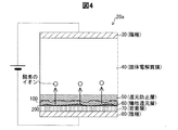
D:反応の概要
図3,4,5を用いて、工程P16における反応の概要を説明する。水素を含む雰囲気中において、陽極30及び陰極80に電位差を生じさせること(工程P16)によって、図3に示されるように、犠牲還元層60に還元生成物100が生じる。還元生成物100は、Bサイトの金属由来が析出したものであり、具体的には遊離した酸化ジルコニウム(ZrO2)や価数の低い酸化ジルコニウム(ZrO)が主である。還元生成物100は、成長する性質を持つ。但し、還元防止層50に達すると、還元が止まり、還元生成物100の成長も止まる。このように還元生成物100が非常に薄い層の段階で還元生成物100の成長が停止するため、固体電解質膜40の破壊は防止される。
D: Outline of reaction The outline of the reaction in Step P16 will be described with reference to FIGS. By causing a potential difference between the anode 30 and the cathode 80 (step P16) in an atmosphere containing hydrogen, the
還元反応がさらに進むと、図4に示されるように金属的な強還元物200が犠牲還元層60に生じる。強還元物200は、金属ジルコニウム(Zr)や、金属ジルコニウムが僅かに酸化されたZr3O等である。
When the reduction reaction further proceeds, a metallic
還元反応がさらに進むと、図5に示されるように強還元物200が成長する。密着層70と強還元物200とが同種の金属なので、密着層70と強還元物200とが強く密着する。
When the reduction reaction further proceeds, the strongly reduced
さらに、還元の過程で酸素のイオン(例えば酸化物イオン)が生じ、陽極30に向けて移動、固体電解質膜40内に拡散する。この酸素のイオンは、固体電解質膜40内に水素イオンを呼び込む働きをする。この働きは、固体電解質膜40に湿気を含ませることによる効果と同等である。 Further, oxygen ions (for example, oxide ions) are generated in the reduction process, move toward the anode 30, and diffuse into the solid electrolyte membrane 40. The oxygen ions serve to attract hydrogen ions into the solid electrolyte membrane 40. This function is equivalent to the effect obtained by including moisture in the solid electrolyte membrane 40.
以下、工程P14〜工程P16の適切な条件を決定するための実施例、比較例について説明する。図6は、これらの実施例、比較例で採用された条件をテーブルによって示す図である。 Hereinafter, examples and comparative examples for determining appropriate conditions for the processes P14 to P16 will be described. FIG. 6 is a table showing the conditions employed in these examples and comparative examples.
E−1:実施例1
ガラス基板上に、陰極80としてパラジウム陰極(厚さ200nm)、固体電解質膜40としてバリウムジルコネート(厚さ1000nm)、陽極30としてパラジウム陽極(厚さ10nm)を積層した複合体20aを製作した(工程P11)。
E-1: Example 1
A composite 20a was fabricated in which a palladium cathode (thickness: 200 nm) as a cathode 80, barium zirconate (thickness: 1000 nm) as a solid electrolyte membrane 40, and a palladium anode (thickness: 10 nm) as an anode 30 were laminated on a glass substrate ( Step P11).
工程P16において印加する電圧値について説明する。還元反応のために必要な理論的な電位差は、以下の通りである。ジルコニウムの標準酸化還元電位は−1.53Vである。水素の酸化反応による標準起電力は1.23Vである。標準酸化還元電位とは、水素と比較した酸化還元電位である。この差を取って、ジルコニウムの還元に必要な電位差が−2.76Vと求まる。 The voltage value applied in the process P16 will be described. The theoretical potential difference required for the reduction reaction is as follows. The standard oxidation-reduction potential of zirconium is -1.53V. The standard electromotive force due to the oxidation reaction of hydrogen is 1.23V. The standard redox potential is the redox potential compared to hydrogen. Taking this difference, the potential difference required for the reduction of zirconium is -2.76V.
通常、酸化還元反応を起こさせるためには、それより僅かに大きな電圧(過電圧)を掛ける必要がある。よって、2.76〜4V、好ましくは3〜4Vの電圧を印加することで犠牲還元層60が還元される。 Usually, in order to cause the oxidation-reduction reaction, it is necessary to apply a voltage (overvoltage) slightly larger than that. Therefore, the sacrificial reduction layer 60 is reduced by applying a voltage of 2.76 to 4V, preferably 3 to 4V.
工程P16を実行する時間(所定時間)について説明する。還元反応に必要な時間は、電位差と温度とによって大きく異なり、適宜実験して最適値を求めることが好ましい。実施例1では、水素を封入し(工程P14)、温度を300℃(工程P15)、電位差を3V(工程P16)として水素吸蔵装置20を製造した。電位差を3.7Vとした条件でも製造した。これらの場合、数分(例えば6min)で還元生成物100が成長した。
The time (predetermined time) which performs process P16 is explained. The time required for the reduction reaction varies greatly depending on the potential difference and the temperature, and it is preferable to obtain an optimum value by performing experiments as appropriate. In Example 1, hydrogen was occluded (process P14), the temperature was set to 300 ° C. (process P15), and the potential difference was set to 3 V (process P16) to manufacture the
還元反応を終了させた後は、電極間の電位差が2.76Vを超えない範囲(例えば1.5V)で使用すれば、還元反応は進行しないため、長期間にわたって使用が可能である。 After the reduction reaction is completed, if the potential difference between the electrodes does not exceed 2.76 V (for example, 1.5 V), the reduction reaction does not proceed, so that it can be used for a long period of time.
実施例1では白濁は生じず、定期的に測定した開放電圧測定は徐々に上昇し、0.2Vに達した。この開放電圧から算出される水素の分圧は1000気圧を超える。つまり、実施例1の場合、陰極80と固体電解質膜40との密着が、この圧力に耐え得ることが確認された。 In Example 1, white turbidity did not occur, and the open-circuit voltage measurement measured periodically increased gradually and reached 0.2V. The partial pressure of hydrogen calculated from this open circuit voltage exceeds 1000 atmospheres. That is, in Example 1, it was confirmed that the adhesion between the cathode 80 and the solid electrolyte membrane 40 can withstand this pressure.
吸蔵後の水素吸蔵装置20の断面を電子顕微鏡で観察し、蛍光X線による元素分析を実施したところ、陰極80と固体電解質膜40との界面にジルコニウムの多い層が検出された。これは強還元物200として生成した金属層のジルコニウムであると考えられる。この強還元物200と密着層70とが両方ともジルコニウムであるので、密着性が向上すると考えられる。
When the cross section of the
さらに、実施例1の場合、還元の過程で発生する酸素のイオンによって水が生成し、固体電解質膜40に保持されるため、水分を添加しなくても、固体電解質膜40に水素イオン伝導性が発現する。 Furthermore, in the case of Example 1, since water is generated by oxygen ions generated in the reduction process and is retained in the solid electrolyte membrane 40, the hydrogen ion conductivity is added to the solid electrolyte membrane 40 without adding moisture. Is expressed.
E−2:比較例1
工程P15において、複合体20aを水素ガス中で270℃に加熱し、工程P16において、陽極30と陰極80との電位差を2Vに設定して、水素吸蔵装置20を製造した。この条件下においては、吸蔵された水素の圧力で固体電解質膜40が剥離、飛散してしまった。2Vでは還元反応が起こらないからだと考えられる。
E-2: Comparative Example 1
In step P15, the composite 20a was heated to 270 ° C. in hydrogen gas. In step P16, the potential difference between the anode 30 and the cathode 80 was set to 2 V, and the
E−3:比較例2
工程P15において、複合体20aを水素ガス中で270℃に加熱し、工程P16において、陽極30と陰極80との電位差を15Vに設定して、水素吸蔵装置20を製造した。この場合は、絶縁破壊が起こり、スパークして固体電解質膜40が破壊してしまった。比較例2では、固体電解質膜40の厚みは1μmであった。よって、固体電解質膜40中の電界強度は、15MV/m以下に抑えることが好ましいことがわかる。
E-3: Comparative Example 2
In step P15, the composite 20a was heated to 270 ° C. in hydrogen gas. In step P16, the potential difference between the anode 30 and the cathode 80 was set to 15 V, and the
E−4:比較例3
工程P16において、陽極30と陰極80との電位差を10Vに設定した。この場合、20min間の電圧印加後、過剰な還元反応によって固体電解質膜40が破壊し、白濁が生じた。この現象は、還元防止層50も還元されたことによると考えられる。
E-4: Comparative Example 3
In Step P16, the potential difference between the anode 30 and the cathode 80 was set to 10V. In this case, after applying the voltage for 20 minutes, the solid electrolyte membrane 40 was destroyed by an excessive reduction reaction, and white turbidity was generated. This phenomenon is considered due to the reduction of the reduction preventing layer 50 as well.
E−5:比較例4
工程P14を実行せず、工程P16において、水素ガスのない雰囲気(真空)で電圧を印加して、水素吸蔵装置20を製造した。この場合、細かい気泡上に陽極30が剥離する現象が起きた。これは、還元によって生じた酸素が、陽極30でガスとして発生し、陽極30を押し剥がしたからと考えられる。
E-5: Comparative Example 4
Step P14 was not performed, and in step P16, a voltage was applied in an atmosphere (vacuum) without hydrogen gas to manufacture the
雰囲気に水素ガスが含まれていた条件においてこのような現象が見られないのは、酸素のイオンが陽極付近で水素イオンと結合して水になり、そのまま固体電解質膜40中に保持されたからと考えられる。 Such a phenomenon is not observed under the condition where the hydrogen gas is included in the atmosphere because the oxygen ions are combined with the hydrogen ions in the vicinity of the anode to be water and are retained in the solid electrolyte membrane 40 as they are. Conceivable.
E−6:実施例2
工程P14において封入する水素の分圧、並びに、工程P16における所定時間および温度の関係を変化させて、水素吸蔵装置20を製造した。(a)150℃の場合、時間は1hour、水素分圧は100kPaで充分な気泡抑制効果が得られた。(b)270℃の場合、時間は4〜6min、水素分圧は1kPaで充分な気泡抑制効果が得られた。(c)500℃の場合、時間は1min、水素分圧は10Paで充分な気泡抑制効果が得られた。
E-6: Example 2
The
還元反応の進行速度は、アレニウス則理論に従うと考えられる。よって、温度が高ければ、短時間で反応が完了する。アレニウス則理論によれば、温度の影響は非常に大きく、最適な処理時間は数桁にわたって大きく変化するので、一概には決められない。したがって実験によって適宜決定するのが好ましい。なお、水素分圧が高すぎると、還元反応が充分に進行しないうちに水素が陰極80に供給される。この結果、高い圧力が発生し、陰極80の剥離を招いてしまう。よって、水素分圧は、上記のように小さな値が好ましい。 The rate of progress of the reduction reaction is thought to follow Arrhenius law theory. Therefore, if the temperature is high, the reaction is completed in a short time. According to the Arrhenius theory, the influence of temperature is very large, and the optimum processing time varies greatly over several orders of magnitude, so it cannot be determined unconditionally. Therefore, it is preferable to determine appropriately by experiment. If the hydrogen partial pressure is too high, hydrogen is supplied to the cathode 80 before the reduction reaction proceeds sufficiently. As a result, a high pressure is generated and the cathode 80 is peeled off. Therefore, the hydrogen partial pressure is preferably a small value as described above.
E−7:実施例3
複合体20aの製造時においてアルゴン雰囲気ガスの圧力を制御して、水素吸蔵装置20を製造した。「C−1:複合体20aの製造手順(工程P11)」として既に説明した製造手順を一部、変更して複合体20aを製造した。変更点は、次の通りである。製造手順の(3)において、アルゴン雰囲気ガスの圧力を0.9Paに設定し、50nmの犠牲還元層60を陰極80上に形成した。製造手順の(4)において、アルゴン雰囲気ガスの圧力を0.3Paに下げて、50nmの還元防止層50を形成した。製造手順の(5)において、アルゴン雰囲気ガスの圧力を0.67Paに設定し、1000nmの固体電解質膜40を形成した。この後、陽極30を形成して、複合体20aを完成させた。
E-7: Example 3
The
工程P15において温度260℃に加熱し、工程P16においては電圧6Vを20min、印加した。その後、完成した水素吸蔵装置20を用いて水素を吸蔵した。具体的には、印加電圧を2Vに下げて水素ガスを封入し、陰極80に水素を吸蔵させた。この場合、0.3Vに達する開放電圧が得られた。この後、逆電圧を印加しても、固体電解質膜40の剥離は起きなかった。従来、頻繁に発生していた固体電解質膜40の白濁も殆ど起きなかった。この理由は、20minという比較的長い還元処理を施したことで、ジルコニウムの還元による密着が確実に得られたこと、及び、還元防止層50が設けられていることで、還元の進行による固体電解質膜40の破壊が起きなかったことだと考えられる。
In step P15, the temperature was heated to 260 ° C., and in step P16, a voltage of 6 V was applied for 20 minutes. Thereafter, hydrogen was stored using the completed
E−8:比較例5
陽極30、固体電解質膜40及び陰極80が積層した構造を有する複合体21a(図7)を用いて、水素吸蔵装置21を製造した。つまり、還元防止層50、犠牲還元層60及び密着層70を廃止した水素吸蔵装置を製造した。
E-8: Comparative Example 5
The
工程P14において10kPa(0.01MPa)の窒素を封入し、工程P15において280〜300℃に加熱し、工程P16において3Vを30min、4〜5Vを30min印加した。この場合、水素吸蔵装置21の表面が僅かに白濁し、干渉による色に変化が見られた。白濁は、微小な剥離とクラックとによるものだった。表面の一部をナイフで削った端部には、固体電解質膜40が陰極80に固着している様子が観察できた。微小な剥離は加熱するだけでも発生することがあり、製膜時の不純物が原因と考えられる。干渉色の変化は、Zrの還元で膜厚が変化したことによると考えられる。Zrの析出が起きてPdとの固着が起こっているものと推測できる。
In Step P14, 10 kPa (0.01 MPa) nitrogen was sealed, and in Step P15, heating was performed at 280 to 300 ° C., and in Step P16, 3 V was applied for 30 minutes and 4 to 5 V was applied for 30 minutes. In this case, the surface of the
E−9:実施例4
複合体21aを用いて、工程P14において10kPa(0.01MPa)の窒素を封入し、付きのように条件を順番に変更しながら工程P15,工程P16を繰り返した。(1)190℃ 3.8V 1min、(2)215℃ 3.7V 1min、(3)245℃ 3.7V 1min、(4)260℃ 3.8V 2min。この後、(5)水素同位体ガスの分圧を10kPa(0.01MPa)とし、275℃ 3.7V 1minに変更した。このように、(1)〜(5)で合計6min電圧を印加した。
E-9: Example 4
Using the composite 21a, nitrogen of 10 kPa (0.01 MPa) was sealed in Step P14, and Step P15 and Step P16 were repeated while changing the conditions in order as indicated. (1) 190 ° C 3.8V 1min, (2) 215 ° C 3.7V 1min, (3) 245 ° C 3.7V 1min, (4) 260 ° C 3.8V 2min. Thereafter, (5) the partial pressure of the hydrogen isotope gas was changed to 10 kPa (0.01 MPa) and changed to 275 ° C. and 3.7 V for 1 min. Thus, a total voltage of 6 min was applied in (1) to (5).
実施例4の水素吸蔵装置20では、開放電圧の測定時に固体電解質膜40の一部が剥離した。固体電解質膜40は結晶性のため密着性が良くなく、還元処理をしない従来の場合では全面が剥離することに比べると、著しく改善された。このように、還元防止層50、犠牲還元層60及び密着層70が無くても、還元処理によって高圧の水素吸蔵が達成された。なお、高圧吸蔵が達成された場合に見られるPd陰極の小穴が発生した。
In the
E−10:実施例5
複合体21aを用い、工程P14において10kPaの水素同位体を封入し、工程P15において270℃に加熱し、工程P16において3〜4Vを30sec印加した。実施例4に比べて印加時間が短いのは、印加の最初から水素同位体雰囲気だったので、陰極80が急激に水素同位体を吸蔵し、短時間でも充分に吸蔵されるからである。部分的に剥離が生じたが、剥がれずに残った部位では良好な吸蔵ができたと考えられる。なお、陰極80に小穴の発生が見られた。
E-10: Example 5
Using the complex 21a, a hydrogen isotope of 10 kPa was enclosed in Step P14, heated to 270 ° C. in Step P15, and 3 to 4 V was applied for 30 seconds in Step P16. The reason why the application time is shorter than that in Example 4 is that since the hydrogen isotope atmosphere was applied from the beginning of the application, the cathode 80 suddenly occludes the hydrogen isotope and is sufficiently occluded even in a short time. Although partial peeling occurred, it was considered that good occlusion was achieved at the portion that remained without peeling. In addition, small holes were observed in the cathode 80.
E−11:実施例6
複合体21aを用い、工程P15において260℃に加熱し、工程P16において3〜4Vを1min印加した。実施例6では、極めて高圧の吸蔵が実現されたことが、以下の現象から推測される。陰極80に発生した小穴は、非常に高密度になった。また、開放電圧の測定時に、陰極80の一部がガラス基板から剥離して飛ぶ現象が発生した。この現象は、開放電圧の測定時に印加電圧がほぼゼロになることにより、高圧(GPaオーダー)の水素が発生したため、ガラス基板と陰極80の界面がこの圧力に耐えられなくなったからだと考えられる。つまり、この現象は、固体電解質膜40は剥離しておらず、この圧力に耐えていることを示唆している。
E-11: Example 6
The composite 21a was used and heated to 260 ° C. in Step P15, and 3 to 4 V was applied for 1 min in Step P16. In Example 6, it is inferred from the following phenomenon that extremely high pressure occlusion was realized. The small holes generated in the cathode 80 became very dense. Further, when the open circuit voltage was measured, a phenomenon in which a part of the cathode 80 was peeled off from the glass substrate occurred. This phenomenon is considered to be because the interface between the glass substrate and the cathode 80 cannot withstand this pressure because high-voltage (GPa order) hydrogen was generated when the applied voltage became almost zero when measuring the open circuit voltage. That is, this phenomenon suggests that the solid electrolyte membrane 40 does not peel off and can withstand this pressure.
F:他の実施形態
本発明は、本明細書の実施形態や実施例、変形例に限られるものではなく、その趣旨を逸脱しない範囲において種々の構成で実現できる。例えば、発明の概要の欄に記載した各形態中の技術的特徴に対応する実施形態、実施例、変形例中の技術的特徴は、先述の課題の一部又は全部を解決するために、あるいは、先述の効果の一部又は全部を達成するために、適宜、差し替えや、組み合わせを行うことができる。その技術的特徴が本明細書中に必須なものとして説明されていなければ、適宜、削除できる。例えば、以下のものが例示される。
F: Other Embodiments The present invention is not limited to the embodiments, examples, and modifications of the present specification, and can be realized with various configurations without departing from the spirit thereof. For example, the technical features in the embodiments, examples, and modifications corresponding to the technical features in the embodiments described in the summary section of the invention are to solve some or all of the above-described problems, or In order to achieve part or all of the effects described above, replacement or combination can be performed as appropriate. If the technical feature is not described as essential in this specification, it can be deleted as appropriate. For example, the following are exemplified.
実施例における工程P15の温度は、150℃以上に設定したが、130℃〜150℃でもよい。理由は、次の通りである。工程P15において、130℃に達した時点からPd陰極と雰囲気中との水素分圧の差に起因する開放電圧の発生が観測された。これはバリウムジルコネートが130℃以上で固体電解質としての性質を発揮している事を示している。バリウムジルコネートが固体電解質として機能している場合に、先述した処理においてジルコニウムが還元されると考えられるので、バリウムジルコネートにおいては130℃以上で処理を行うのが好ましい。 Although the temperature of process P15 in an example was set as 150 ° C or more, 130 ° C-150 ° C may be sufficient. The reason is as follows. In Step P15, generation of an open-circuit voltage due to a difference in hydrogen partial pressure between the Pd cathode and the atmosphere was observed from the time when the temperature reached 130 ° C. This indicates that barium zirconate exhibits properties as a solid electrolyte at 130 ° C. or higher. When barium zirconate functions as a solid electrolyte, it is considered that zirconium is reduced in the above-described treatment. Therefore, it is preferable to carry out the treatment at 130 ° C. or higher for barium zirconate.
密着層を廃止してもよい。この場合であっても、ジルコニウム及びパラジウムは金属同士であるので、強還元物と陰極80との密着性が向上すると考えられる。
密着層を廃止した場合、陰極をジルコニウムで構成してもよい。このようにすれば、密着層を廃止しつつ、密着層がある場合と同等の密着性を得ることができる。ジルコニウムによる陰極を採用する場合、陰極の厚さを1〜100nm、より好ましくは3〜50nmに設定すると、陰極の水素透過性を向上させることができる。
固体電解質は、バリウムジルコネートでなくても、その他の種類、例えばバリウムとセリウムとによるものでもよい。
陰極として使用する部位でなくてもよく、例えば陽極に使用する部位であっても、この構造を適用し、さらにその製造段階において負の電圧を印加する処理を実施して密着を向上させた後に陽極として使用に供するという応用に対しても適用できる。
密着層、犠牲還元層、還元防止層、及び高い陰電位を掛ける処理、及びこの処理時に水素ガスを添加することの5つ全てを備えることが必要である訳ではなく、このうちの1つ又は複数の組み合わせだけであっても充分に効果を発揮し得るものである。例えば、犠牲還元層と還元防止層との一方を廃止しても良い。この場合でも、やはり密着性の向上の効果がある。但し、良好な密着が得られる条件と過剰な還元が起きて構造が破壊する条件との間が狭くなるので、適宜、実験によって数値を定めるのが好ましい。
陰極と陽極との両方に本発明を適用できる。
The adhesion layer may be abolished. Even in this case, since zirconium and palladium are metals, it is considered that the adhesion between the strongly reduced product and the cathode 80 is improved.
When the adhesion layer is eliminated, the cathode may be made of zirconium. If it does in this way, adhesiveness equivalent to the case where there exists an adhesion layer can be obtained, eliminating an adhesion layer. When employing a cathode made of zirconium, the hydrogen permeability of the cathode can be improved by setting the thickness of the cathode to 1 to 100 nm, more preferably 3 to 50 nm.
The solid electrolyte may not be barium zirconate but may be of other types, such as barium and cerium.
Even if it is a part used as an anode, for example, even if it is a part used as an anode, after applying this structure and further carrying out a process of applying a negative voltage in the manufacturing stage, the adhesion is improved. The present invention can also be applied to applications in which it is used as an anode.
It is not necessary to have all five of the adhesion layer, the sacrificial reduction layer, the reduction prevention layer, and the process of applying a high negative potential, and the addition of hydrogen gas during this process. Even if only a plurality of combinations are used, sufficient effects can be exhibited. For example, one of the sacrificial reduction layer and the reduction prevention layer may be eliminated. Even in this case, there is an effect of improving adhesion. However, it is preferable to set a numerical value appropriately through experiments because the gap between the condition for obtaining good adhesion and the condition for excessive reduction to occur and the structure breaking down becomes narrow.
The present invention can be applied to both the cathode and the anode.
20…水素吸蔵装置
20a…固体電解質−電極複合体
21…水素吸蔵装置
21a…固体電解質−電極複合体
30…陽極
40…固体電解質膜
50…還元防止層
60…犠牲還元層
70…密着層
80…陰極
100…還元生成物
200…強還元物
DESCRIPTION OF
Claims (3)
130℃以上500℃以下の温度条件かつ水素ガスの存在する雰囲気で、前記ペロブスカイト構造におけるBサイトの金属が還元されるように前記両側の電極間に電圧を印加し、前記両側の電極の少なくとも一方と前記固体電解質との間に前記Bサイトの金属由来の層を析出させる、製造方法。 AB 1-X C X O 3 (0 ≦ X ≦ 0.3) having a perovskite structure composed of a solid electrolyte solid electrolyte on both sides to the electrodes Ru disposed of - a process for the preparation of the electrode assembly,
A voltage is applied between the electrodes on both sides in a temperature condition of 130 ° C. or more and 500 ° C. or less and hydrogen gas is present so that the metal at the B site in the perovskite structure is reduced , and at least one of the electrodes on both sides The metal-derived layer of the B site is deposited between the solid electrolyte and the solid electrolyte.
Priority Applications (1)
| Application Number | Priority Date | Filing Date | Title |
|---|---|---|---|
| JP2014089841A JP6156246B2 (en) | 2014-04-24 | 2014-04-24 | Method for producing solid electrolyte-electrode composite |
Applications Claiming Priority (1)
| Application Number | Priority Date | Filing Date | Title |
|---|---|---|---|
| JP2014089841A JP6156246B2 (en) | 2014-04-24 | 2014-04-24 | Method for producing solid electrolyte-electrode composite |
Publications (3)
| Publication Number | Publication Date |
|---|---|
| JP2015211484A JP2015211484A (en) | 2015-11-24 |
| JP2015211484A5 JP2015211484A5 (en) | 2016-07-14 |
| JP6156246B2 true JP6156246B2 (en) | 2017-07-05 |
Family
ID=54613341
Family Applications (1)
| Application Number | Title | Priority Date | Filing Date |
|---|---|---|---|
| JP2014089841A Active JP6156246B2 (en) | 2014-04-24 | 2014-04-24 | Method for producing solid electrolyte-electrode composite |
Country Status (1)
| Country | Link |
|---|---|
| JP (1) | JP6156246B2 (en) |
Families Citing this family (2)
| Publication number | Priority date | Publication date | Assignee | Title |
|---|---|---|---|---|
| GB201611953D0 (en) * | 2016-07-08 | 2016-08-24 | Univ Court Of The Univ Of St Andrews The | Method |
| CN110710037B (en) * | 2017-03-31 | 2024-03-08 | 密执安州立大学董事会 | System and method for forming a simple lithium metal anode interface with a solid electrolyte |
Family Cites Families (5)
| Publication number | Priority date | Publication date | Assignee | Title |
|---|---|---|---|---|
| JPH08278278A (en) * | 1995-04-03 | 1996-10-22 | Tokyo Yogyo Co Ltd | Hydrogen sensor probe and its manufacturing method |
| JP3274356B2 (en) * | 1996-05-13 | 2002-04-15 | 株式会社日本製鋼所 | Power generation method and apparatus using hydrogen storage alloy |
| JP2005033960A (en) * | 2003-07-10 | 2005-02-03 | Toyota Motor Corp | Thermoelectric conversion hydrogen battery |
| JP5061456B2 (en) * | 2005-12-14 | 2012-10-31 | トヨタ自動車株式会社 | Manufacturing method of fuel cell |
| JP2015059224A (en) * | 2013-09-17 | 2015-03-30 | トヨタ自動車株式会社 | Hydrogen storage device |
-
2014
- 2014-04-24 JP JP2014089841A patent/JP6156246B2/en active Active
Also Published As
| Publication number | Publication date |
|---|---|
| JP2015211484A (en) | 2015-11-24 |
Similar Documents
| Publication | Publication Date | Title |
|---|---|---|
| Achour et al. | Role of nitrogen doping at the surface of titanium nitride thin films towards capacitive charge storage enhancement | |
| JP5807218B2 (en) | Photoelectrode and manufacturing method thereof, photoelectrochemical cell, energy system using the same, and hydrogen generation method | |
| CN113249683B (en) | MAX phase solid solution composite coating with high conductivity, corrosion resistance and long service life, and preparation method and application thereof | |
| JP2008023404A (en) | Hydrogen permeation structure and fuel cell | |
| JP6156246B2 (en) | Method for producing solid electrolyte-electrode composite | |
| JP2015134699A (en) | Oxide film and proton conductive device | |
| JP4992522B2 (en) | Capacitor electrode foil and capacitor using the same | |
| JP2016026987A (en) | Proton-conducting oxide | |
| KR20160010465A (en) | Multi-layer sandwich structure for a solid-state electrolyte | |
| JP4665866B2 (en) | Manufacturing method of valve metal composite electrode foil | |
| JP2008130514A (en) | Deposition method of electrolyte membrane, and manufacturing method of fuel cell | |
| CN106129172B (en) | A kind of crystal silicon solar batteries surface passivation method of adjustable charge density | |
| JP6911812B2 (en) | Anodizing equipment, anodizing method and cathode manufacturing method for anodizing equipment | |
| JP2006314925A (en) | Hydrogen permeable membrane and fuel cell equipped with it | |
| JP2006286537A (en) | Hydrogen permeation structure and its manufacturing method | |
| KR101447023B1 (en) | Method of manufacturing porous composite thin film and the porous composite thin film for electrode | |
| KR20200037000A (en) | Recovery of electrical properties and oxidation stability improvement method for two-dimensional materials | |
| JP2015059224A (en) | Hydrogen storage device | |
| US3491000A (en) | Method of producing vanadium dioxide thin films | |
| TW201605102A (en) | Hydrogen release film | |
| JP5138876B2 (en) | Oxide proton conductive membrane and hydrogen permeable structure including the same | |
| WO2015194471A1 (en) | Hydrogen release film | |
| JP2007117810A (en) | Hydrogen permeable membrane and fuel cell using the same | |
| JP2004016971A (en) | Oxygen permeable body | |
| TW201812811A (en) | Electrolytic capacitor |
Legal Events
| Date | Code | Title | Description |
|---|---|---|---|
| A521 | Written amendment |
Free format text: JAPANESE INTERMEDIATE CODE: A523 Effective date: 20160525 |
|
| A621 | Written request for application examination |
Free format text: JAPANESE INTERMEDIATE CODE: A621 Effective date: 20160525 |
|
| A977 | Report on retrieval |
Free format text: JAPANESE INTERMEDIATE CODE: A971007 Effective date: 20170426 |
|
| TRDD | Decision of grant or rejection written | ||
| A01 | Written decision to grant a patent or to grant a registration (utility model) |
Free format text: JAPANESE INTERMEDIATE CODE: A01 Effective date: 20170509 |
|
| A61 | First payment of annual fees (during grant procedure) |
Free format text: JAPANESE INTERMEDIATE CODE: A61 Effective date: 20170522 |
|
| R151 | Written notification of patent or utility model registration |
Ref document number: 6156246 Country of ref document: JP Free format text: JAPANESE INTERMEDIATE CODE: R151 |