JP6148340B2 - Articles containing urethane (plural)-(meth) acrylate (plural) -silane (co) polymer reaction products - Google Patents
Articles containing urethane (plural)-(meth) acrylate (plural) -silane (co) polymer reaction products Download PDFInfo
- Publication number
- JP6148340B2 JP6148340B2 JP2015526519A JP2015526519A JP6148340B2 JP 6148340 B2 JP6148340 B2 JP 6148340B2 JP 2015526519 A JP2015526519 A JP 2015526519A JP 2015526519 A JP2015526519 A JP 2015526519A JP 6148340 B2 JP6148340 B2 JP 6148340B2
- Authority
- JP
- Japan
- Prior art keywords
- group
- layer
- meth
- polymer
- acrylate
- Prior art date
- Legal status (The legal status is an assumption and is not a legal conclusion. Google has not performed a legal analysis and makes no representation as to the accuracy of the status listed.)
- Expired - Fee Related
Links
- 229920001577 copolymer Polymers 0.000 title claims description 178
- NIXOWILDQLNWCW-UHFFFAOYSA-M Acrylate Chemical compound [O-]C(=O)C=C NIXOWILDQLNWCW-UHFFFAOYSA-M 0.000 title claims description 164
- 229910000077 silane Inorganic materials 0.000 title claims description 54
- JOYRKODLDBILNP-UHFFFAOYSA-N Ethyl urethane Chemical compound CCOC(N)=O JOYRKODLDBILNP-UHFFFAOYSA-N 0.000 title claims description 47
- 239000007795 chemical reaction product Substances 0.000 title claims description 17
- 239000010408 film Substances 0.000 claims description 128
- 238000000034 method Methods 0.000 claims description 87
- 239000000758 substrate Substances 0.000 claims description 77
- 239000002243 precursor Substances 0.000 claims description 71
- 150000001875 compounds Chemical class 0.000 claims description 58
- 230000001681 protective effect Effects 0.000 claims description 54
- -1 acryl group Chemical group 0.000 claims description 41
- 238000000151 deposition Methods 0.000 claims description 41
- 125000002947 alkylene group Chemical group 0.000 claims description 24
- 125000000732 arylene group Chemical group 0.000 claims description 24
- 150000002367 halogens Chemical class 0.000 claims description 15
- 125000003545 alkoxy group Chemical group 0.000 claims description 14
- 239000004973 liquid crystal related substance Substances 0.000 claims description 12
- 239000007787 solid Substances 0.000 claims description 12
- 239000010409 thin film Substances 0.000 claims description 12
- QTBSBXVTEAMEQO-UHFFFAOYSA-N Acetic acid Chemical group CC(O)=O QTBSBXVTEAMEQO-UHFFFAOYSA-N 0.000 claims description 8
- 125000004104 aryloxy group Chemical group 0.000 claims description 8
- 229910052736 halogen Inorganic materials 0.000 claims description 8
- 125000000217 alkyl group Chemical group 0.000 claims description 6
- 125000003118 aryl group Chemical group 0.000 claims description 6
- BLRPTPMANUNPDV-UHFFFAOYSA-N Silane Chemical compound [SiH4] BLRPTPMANUNPDV-UHFFFAOYSA-N 0.000 claims description 5
- 229920006254 polymer film Polymers 0.000 claims description 2
- RTZKZFJDLAIYFH-UHFFFAOYSA-N ether Substances CCOCC RTZKZFJDLAIYFH-UHFFFAOYSA-N 0.000 claims 4
- 239000010410 layer Substances 0.000 description 321
- 230000004888 barrier function Effects 0.000 description 124
- 239000002585 base Substances 0.000 description 49
- 238000000576 coating method Methods 0.000 description 43
- 239000000203 mixture Substances 0.000 description 41
- 239000000463 material Substances 0.000 description 30
- 239000011248 coating agent Substances 0.000 description 28
- 239000002131 composite material Substances 0.000 description 27
- 230000008021 deposition Effects 0.000 description 25
- 230000000712 assembly Effects 0.000 description 22
- 238000000429 assembly Methods 0.000 description 22
- 229910052751 metal Inorganic materials 0.000 description 21
- 239000002184 metal Substances 0.000 description 21
- 230000008569 process Effects 0.000 description 21
- 238000002360 preparation method Methods 0.000 description 20
- 238000004544 sputter deposition Methods 0.000 description 19
- 229920000139 polyethylene terephthalate Polymers 0.000 description 18
- 239000005020 polyethylene terephthalate Substances 0.000 description 18
- 229910052710 silicon Inorganic materials 0.000 description 18
- XLYOFNOQVPJJNP-UHFFFAOYSA-N water Chemical compound O XLYOFNOQVPJJNP-UHFFFAOYSA-N 0.000 description 18
- 229910052782 aluminium Inorganic materials 0.000 description 16
- 238000001704 evaporation Methods 0.000 description 16
- YAIQCYZCSGLAAN-UHFFFAOYSA-N [Si+4].[O-2].[Al+3] Chemical compound [Si+4].[O-2].[Al+3] YAIQCYZCSGLAAN-UHFFFAOYSA-N 0.000 description 14
- 230000032683 aging Effects 0.000 description 14
- QVGXLLKOCUKJST-UHFFFAOYSA-N atomic oxygen Chemical compound [O] QVGXLLKOCUKJST-UHFFFAOYSA-N 0.000 description 14
- 230000005540 biological transmission Effects 0.000 description 14
- 238000006243 chemical reaction Methods 0.000 description 14
- 229910052760 oxygen Inorganic materials 0.000 description 14
- 239000001301 oxygen Substances 0.000 description 14
- 239000011241 protective layer Substances 0.000 description 14
- 238000012360 testing method Methods 0.000 description 14
- 239000000178 monomer Substances 0.000 description 13
- 150000001252 acrylic acid derivatives Chemical class 0.000 description 12
- 238000005229 chemical vapour deposition Methods 0.000 description 12
- 229910010272 inorganic material Inorganic materials 0.000 description 12
- 239000011147 inorganic material Substances 0.000 description 12
- 239000007788 liquid Substances 0.000 description 12
- XUIMIQQOPSSXEZ-UHFFFAOYSA-N Silicon Chemical compound [Si] XUIMIQQOPSSXEZ-UHFFFAOYSA-N 0.000 description 11
- 229920000642 polymer Polymers 0.000 description 11
- 239000010703 silicon Substances 0.000 description 11
- 239000000126 substance Substances 0.000 description 11
- 230000015572 biosynthetic process Effects 0.000 description 10
- VYPSYNLAJGMNEJ-UHFFFAOYSA-N Silicium dioxide Chemical compound O=[Si]=O VYPSYNLAJGMNEJ-UHFFFAOYSA-N 0.000 description 9
- XAGFODPZIPBFFR-UHFFFAOYSA-N aluminium Chemical compound [Al] XAGFODPZIPBFFR-UHFFFAOYSA-N 0.000 description 9
- 230000008859 change Effects 0.000 description 9
- 230000000052 comparative effect Effects 0.000 description 9
- 239000007789 gas Substances 0.000 description 9
- 238000010438 heat treatment Methods 0.000 description 9
- 238000004519 manufacturing process Methods 0.000 description 9
- 239000000047 product Substances 0.000 description 9
- 125000004429 atom Chemical group 0.000 description 8
- 238000009499 grossing Methods 0.000 description 8
- 150000004767 nitrides Chemical class 0.000 description 8
- 125000004430 oxygen atom Chemical group O* 0.000 description 8
- 239000004065 semiconductor Substances 0.000 description 8
- 239000000243 solution Substances 0.000 description 8
- UKLDJPRMSDWDSL-UHFFFAOYSA-L [dibutyl(dodecanoyloxy)stannyl] dodecanoate Chemical compound CCCCCCCCCCCC(=O)O[Sn](CCCC)(CCCC)OC(=O)CCCCCCCCCCC UKLDJPRMSDWDSL-UHFFFAOYSA-L 0.000 description 7
- VEBCLRKUSAGCDF-UHFFFAOYSA-N ac1mi23b Chemical compound C1C2C3C(COC(=O)C=C)CCC3C1C(COC(=O)C=C)C2 VEBCLRKUSAGCDF-UHFFFAOYSA-N 0.000 description 7
- 230000009977 dual effect Effects 0.000 description 7
- 230000008020 evaporation Effects 0.000 description 7
- XKRFYHLGVUSROY-UHFFFAOYSA-N Argon Chemical compound [Ar] XKRFYHLGVUSROY-UHFFFAOYSA-N 0.000 description 6
- UFWIBTONFRDIAS-UHFFFAOYSA-N Naphthalene Chemical compound C1=CC=CC2=CC=CC=C21 UFWIBTONFRDIAS-UHFFFAOYSA-N 0.000 description 6
- 230000008901 benefit Effects 0.000 description 6
- 238000004132 cross linking Methods 0.000 description 6
- 238000001723 curing Methods 0.000 description 6
- 238000005538 encapsulation Methods 0.000 description 6
- 229920000840 ethylene tetrafluoroethylene copolymer Polymers 0.000 description 6
- 239000011112 polyethylene naphthalate Substances 0.000 description 6
- 239000002904 solvent Substances 0.000 description 6
- 239000004642 Polyimide Substances 0.000 description 5
- 239000004721 Polyphenylene oxide Substances 0.000 description 5
- 229910052799 carbon Inorganic materials 0.000 description 5
- 230000007423 decrease Effects 0.000 description 5
- 230000000694 effects Effects 0.000 description 5
- 238000010894 electron beam technology Methods 0.000 description 5
- 229910052755 nonmetal Inorganic materials 0.000 description 5
- 230000003287 optical effect Effects 0.000 description 5
- 238000000623 plasma-assisted chemical vapour deposition Methods 0.000 description 5
- 229920001721 polyimide Polymers 0.000 description 5
- 229920001343 polytetrafluoroethylene Polymers 0.000 description 5
- 239000004810 polytetrafluoroethylene Substances 0.000 description 5
- 238000012545 processing Methods 0.000 description 5
- 239000002096 quantum dot Substances 0.000 description 5
- 229910052814 silicon oxide Inorganic materials 0.000 description 5
- 238000005507 spraying Methods 0.000 description 5
- 238000005477 sputtering target Methods 0.000 description 5
- 238000007740 vapor deposition Methods 0.000 description 5
- FMGBDYLOANULLW-UHFFFAOYSA-N 3-isocyanatopropyl(trimethoxy)silane Chemical compound CO[Si](OC)(OC)CCCN=C=O FMGBDYLOANULLW-UHFFFAOYSA-N 0.000 description 4
- IJGRMHOSHXDMSA-UHFFFAOYSA-N Atomic nitrogen Chemical compound N#N IJGRMHOSHXDMSA-UHFFFAOYSA-N 0.000 description 4
- GYHNNYVSQQEPJS-UHFFFAOYSA-N Gallium Chemical compound [Ga] GYHNNYVSQQEPJS-UHFFFAOYSA-N 0.000 description 4
- NIXOWILDQLNWCW-UHFFFAOYSA-N acrylic acid group Chemical group C(C=C)(=O)O NIXOWILDQLNWCW-UHFFFAOYSA-N 0.000 description 4
- 230000001112 coagulating effect Effects 0.000 description 4
- 230000007547 defect Effects 0.000 description 4
- 238000005516 engineering process Methods 0.000 description 4
- 125000001153 fluoro group Chemical group F* 0.000 description 4
- 239000011888 foil Substances 0.000 description 4
- 125000000524 functional group Chemical group 0.000 description 4
- 229910052739 hydrogen Inorganic materials 0.000 description 4
- AMGQUBHHOARCQH-UHFFFAOYSA-N indium;oxotin Chemical compound [In].[Sn]=O AMGQUBHHOARCQH-UHFFFAOYSA-N 0.000 description 4
- 229910044991 metal oxide Inorganic materials 0.000 description 4
- 150000004706 metal oxides Chemical class 0.000 description 4
- 239000003921 oil Substances 0.000 description 4
- 229920003229 poly(methyl methacrylate) Polymers 0.000 description 4
- 229920002492 poly(sulfone) Polymers 0.000 description 4
- 229920000515 polycarbonate Polymers 0.000 description 4
- 239000004417 polycarbonate Substances 0.000 description 4
- 229920000307 polymer substrate Polymers 0.000 description 4
- 239000004926 polymethyl methacrylate Substances 0.000 description 4
- 230000001737 promoting effect Effects 0.000 description 4
- 230000004224 protection Effects 0.000 description 4
- 229910052761 rare earth metal Inorganic materials 0.000 description 4
- 150000002910 rare earth metals Chemical class 0.000 description 4
- 238000005546 reactive sputtering Methods 0.000 description 4
- 241000894007 species Species 0.000 description 4
- 230000003595 spectral effect Effects 0.000 description 4
- FRGPKMWIYVTFIQ-UHFFFAOYSA-N triethoxy(3-isocyanatopropyl)silane Chemical compound CCO[Si](OCC)(OCC)CCCN=C=O FRGPKMWIYVTFIQ-UHFFFAOYSA-N 0.000 description 4
- 238000001771 vacuum deposition Methods 0.000 description 4
- 239000012808 vapor phase Substances 0.000 description 4
- 229920002554 vinyl polymer Polymers 0.000 description 4
- ZODNDDPVCIAZIQ-UHFFFAOYSA-N (2-hydroxy-3-prop-2-enoyloxypropyl) 2-methylprop-2-enoate Chemical compound CC(=C)C(=O)OCC(O)COC(=O)C=C ZODNDDPVCIAZIQ-UHFFFAOYSA-N 0.000 description 3
- 229920002818 (Hydroxyethyl)methacrylate Polymers 0.000 description 3
- OMIGHNLMNHATMP-UHFFFAOYSA-N 2-hydroxyethyl prop-2-enoate Chemical compound OCCOC(=O)C=C OMIGHNLMNHATMP-UHFFFAOYSA-N 0.000 description 3
- WOBHKFSMXKNTIM-UHFFFAOYSA-N Hydroxyethyl methacrylate Chemical compound CC(=C)C(=O)OCCO WOBHKFSMXKNTIM-UHFFFAOYSA-N 0.000 description 3
- 229930040373 Paraformaldehyde Natural products 0.000 description 3
- 239000004696 Poly ether ether ketone Substances 0.000 description 3
- 239000004962 Polyamide-imide Substances 0.000 description 3
- 239000004695 Polyether sulfone Substances 0.000 description 3
- 239000004954 Polyphthalamide Substances 0.000 description 3
- 239000004820 Pressure-sensitive adhesive Substances 0.000 description 3
- 229910008051 Si-OH Inorganic materials 0.000 description 3
- 229910006358 Si—OH Inorganic materials 0.000 description 3
- GWEVSGVZZGPLCZ-UHFFFAOYSA-N Titan oxide Chemical compound O=[Ti]=O GWEVSGVZZGPLCZ-UHFFFAOYSA-N 0.000 description 3
- 150000004703 alkoxides Chemical class 0.000 description 3
- XYLMUPLGERFSHI-UHFFFAOYSA-N alpha-Methylstyrene Chemical compound CC(=C)C1=CC=CC=C1 XYLMUPLGERFSHI-UHFFFAOYSA-N 0.000 description 3
- 229910052786 argon Inorganic materials 0.000 description 3
- 239000012298 atmosphere Substances 0.000 description 3
- 238000005452 bending Methods 0.000 description 3
- 230000032798 delamination Effects 0.000 description 3
- 238000005137 deposition process Methods 0.000 description 3
- 239000011521 glass Substances 0.000 description 3
- 238000006460 hydrolysis reaction Methods 0.000 description 3
- 230000006872 improvement Effects 0.000 description 3
- 238000011065 in-situ storage Methods 0.000 description 3
- 229910052809 inorganic oxide Inorganic materials 0.000 description 3
- 238000005259 measurement Methods 0.000 description 3
- 150000001247 metal acetylides Chemical class 0.000 description 3
- 238000012986 modification Methods 0.000 description 3
- 230000004048 modification Effects 0.000 description 3
- TWNQGVIAIRXVLR-UHFFFAOYSA-N oxo(oxoalumanyloxy)alumane Chemical compound O=[Al]O[Al]=O TWNQGVIAIRXVLR-UHFFFAOYSA-N 0.000 description 3
- 229920003207 poly(ethylene-2,6-naphthalate) Polymers 0.000 description 3
- 229920002312 polyamide-imide Polymers 0.000 description 3
- 229920006393 polyether sulfone Polymers 0.000 description 3
- 229920002530 polyetherether ketone Polymers 0.000 description 3
- 229920006324 polyoxymethylene Polymers 0.000 description 3
- 229920006380 polyphenylene oxide Polymers 0.000 description 3
- 229920006375 polyphtalamide Polymers 0.000 description 3
- 238000010526 radical polymerization reaction Methods 0.000 description 3
- 239000000376 reactant Substances 0.000 description 3
- 238000002207 thermal evaporation Methods 0.000 description 3
- 238000002834 transmittance Methods 0.000 description 3
- WYTZZXDRDKSJID-UHFFFAOYSA-N (3-aminopropyl)triethoxysilane Chemical compound CCO[Si](OCC)(OCC)CCCN WYTZZXDRDKSJID-UHFFFAOYSA-N 0.000 description 2
- LEJBBGNFPAFPKQ-UHFFFAOYSA-N 2-(2-prop-2-enoyloxyethoxy)ethyl prop-2-enoate Chemical compound C=CC(=O)OCCOCCOC(=O)C=C LEJBBGNFPAFPKQ-UHFFFAOYSA-N 0.000 description 2
- 238000005033 Fourier transform infrared spectroscopy Methods 0.000 description 2
- CERQOIWHTDAKMF-UHFFFAOYSA-M Methacrylate Chemical compound CC(=C)C([O-])=O CERQOIWHTDAKMF-UHFFFAOYSA-M 0.000 description 2
- 239000004697 Polyetherimide Substances 0.000 description 2
- BUGBHKTXTAQXES-UHFFFAOYSA-N Selenium Chemical compound [Se] BUGBHKTXTAQXES-UHFFFAOYSA-N 0.000 description 2
- PPBRXRYQALVLMV-UHFFFAOYSA-N Styrene Chemical compound C=CC1=CC=CC=C1 PPBRXRYQALVLMV-UHFFFAOYSA-N 0.000 description 2
- RTAQQCXQSZGOHL-UHFFFAOYSA-N Titanium Chemical compound [Ti] RTAQQCXQSZGOHL-UHFFFAOYSA-N 0.000 description 2
- DAKWPKUUDNSNPN-UHFFFAOYSA-N Trimethylolpropane triacrylate Chemical compound C=CC(=O)OCC(CC)(COC(=O)C=C)COC(=O)C=C DAKWPKUUDNSNPN-UHFFFAOYSA-N 0.000 description 2
- QCWXUUIWCKQGHC-UHFFFAOYSA-N Zirconium Chemical compound [Zr] QCWXUUIWCKQGHC-UHFFFAOYSA-N 0.000 description 2
- HVVWZTWDBSEWIH-UHFFFAOYSA-N [2-(hydroxymethyl)-3-prop-2-enoyloxy-2-(prop-2-enoyloxymethyl)propyl] prop-2-enoate Chemical compound C=CC(=O)OCC(CO)(COC(=O)C=C)COC(=O)C=C HVVWZTWDBSEWIH-UHFFFAOYSA-N 0.000 description 2
- MWGMEGAYPPQWFG-UHFFFAOYSA-N [SiH4].OC(=O)C=C Chemical compound [SiH4].OC(=O)C=C MWGMEGAYPPQWFG-UHFFFAOYSA-N 0.000 description 2
- 239000003153 chemical reaction reagent Substances 0.000 description 2
- 238000001816 cooling Methods 0.000 description 2
- HVMJUDPAXRRVQO-UHFFFAOYSA-N copper indium Chemical compound [Cu].[In] HVMJUDPAXRRVQO-UHFFFAOYSA-N 0.000 description 2
- 239000007822 coupling agent Substances 0.000 description 2
- 238000000280 densification Methods 0.000 description 2
- 125000004386 diacrylate group Chemical group 0.000 description 2
- 238000001227 electron beam curing Methods 0.000 description 2
- 239000008393 encapsulating agent Substances 0.000 description 2
- 229910052733 gallium Inorganic materials 0.000 description 2
- 229920001519 homopolymer Polymers 0.000 description 2
- 150000002739 metals Chemical class 0.000 description 2
- 229910052757 nitrogen Inorganic materials 0.000 description 2
- 150000002894 organic compounds Chemical class 0.000 description 2
- 238000004806 packaging method and process Methods 0.000 description 2
- 238000005240 physical vapour deposition Methods 0.000 description 2
- 229920003023 plastic Polymers 0.000 description 2
- 239000004033 plastic Substances 0.000 description 2
- BASFCYQUMIYNBI-UHFFFAOYSA-N platinum Chemical compound [Pt] BASFCYQUMIYNBI-UHFFFAOYSA-N 0.000 description 2
- 229920000570 polyether Polymers 0.000 description 2
- 229920001601 polyetherimide Polymers 0.000 description 2
- 229920002635 polyurethane Polymers 0.000 description 2
- 239000004814 polyurethane Substances 0.000 description 2
- KCTAWXVAICEBSD-UHFFFAOYSA-N prop-2-enoyloxy prop-2-eneperoxoate Chemical compound C=CC(=O)OOOC(=O)C=C KCTAWXVAICEBSD-UHFFFAOYSA-N 0.000 description 2
- 229910052711 selenium Inorganic materials 0.000 description 2
- 239000011669 selenium Substances 0.000 description 2
- 150000004756 silanes Chemical class 0.000 description 2
- 239000000377 silicon dioxide Substances 0.000 description 2
- 239000011343 solid material Substances 0.000 description 2
- 238000001228 spectrum Methods 0.000 description 2
- 230000035882 stress Effects 0.000 description 2
- 238000010998 test method Methods 0.000 description 2
- 230000008646 thermal stress Effects 0.000 description 2
- 229920001187 thermosetting polymer Polymers 0.000 description 2
- 229910052719 titanium Inorganic materials 0.000 description 2
- 239000010936 titanium Substances 0.000 description 2
- 229910052726 zirconium Inorganic materials 0.000 description 2
- PSGCQDPCAWOCSH-UHFFFAOYSA-N (4,7,7-trimethyl-3-bicyclo[2.2.1]heptanyl) prop-2-enoate Chemical compound C1CC2(C)C(OC(=O)C=C)CC1C2(C)C PSGCQDPCAWOCSH-UHFFFAOYSA-N 0.000 description 1
- MYWOJODOMFBVCB-UHFFFAOYSA-N 1,2,6-trimethylphenanthrene Chemical compound CC1=CC=C2C3=CC(C)=CC=C3C=CC2=C1C MYWOJODOMFBVCB-UHFFFAOYSA-N 0.000 description 1
- BCMCBBGGLRIHSE-UHFFFAOYSA-N 1,3-benzoxazole Chemical compound C1=CC=C2OC=NC2=C1 BCMCBBGGLRIHSE-UHFFFAOYSA-N 0.000 description 1
- SMZOUWXMTYCWNB-UHFFFAOYSA-N 2-(2-methoxy-5-methylphenyl)ethanamine Chemical compound COC1=CC=C(C)C=C1CCN SMZOUWXMTYCWNB-UHFFFAOYSA-N 0.000 description 1
- YIJYFLXQHDOQGW-UHFFFAOYSA-N 2-[2,4,6-trioxo-3,5-bis(2-prop-2-enoyloxyethyl)-1,3,5-triazinan-1-yl]ethyl prop-2-enoate Chemical compound C=CC(=O)OCCN1C(=O)N(CCOC(=O)C=C)C(=O)N(CCOC(=O)C=C)C1=O YIJYFLXQHDOQGW-UHFFFAOYSA-N 0.000 description 1
- RICKKZXCGCSLIU-UHFFFAOYSA-N 2-[2-[carboxymethyl-[[3-hydroxy-5-(hydroxymethyl)-2-methylpyridin-4-yl]methyl]amino]ethyl-[[3-hydroxy-5-(hydroxymethyl)-2-methylpyridin-4-yl]methyl]amino]acetic acid Chemical compound CC1=NC=C(CO)C(CN(CCN(CC(O)=O)CC=2C(=C(C)N=CC=2CO)O)CC(O)=O)=C1O RICKKZXCGCSLIU-UHFFFAOYSA-N 0.000 description 1
- FDSUVTROAWLVJA-UHFFFAOYSA-N 2-[[3-hydroxy-2,2-bis(hydroxymethyl)propoxy]methyl]-2-(hydroxymethyl)propane-1,3-diol;prop-2-enoic acid Chemical compound OC(=O)C=C.OC(=O)C=C.OC(=O)C=C.OC(=O)C=C.OC(=O)C=C.OCC(CO)(CO)COCC(CO)(CO)CO FDSUVTROAWLVJA-UHFFFAOYSA-N 0.000 description 1
- QMOCHTLIIWRLQV-UHFFFAOYSA-N 2-[methyl(3-trimethoxysilylpropyl)amino]ethanol Chemical compound CO[Si](OC)(OC)CCCN(C)CCO QMOCHTLIIWRLQV-UHFFFAOYSA-N 0.000 description 1
- IEVADDDOVGMCSI-UHFFFAOYSA-N 2-hydroxybutyl 2-methylprop-2-enoate Chemical compound CCC(O)COC(=O)C(C)=C IEVADDDOVGMCSI-UHFFFAOYSA-N 0.000 description 1
- GNSFRPWPOGYVLO-UHFFFAOYSA-N 3-hydroxypropyl 2-methylprop-2-enoate Chemical compound CC(=C)C(=O)OCCCO GNSFRPWPOGYVLO-UHFFFAOYSA-N 0.000 description 1
- QZPSOSOOLFHYRR-UHFFFAOYSA-N 3-hydroxypropyl prop-2-enoate Chemical compound OCCCOC(=O)C=C QZPSOSOOLFHYRR-UHFFFAOYSA-N 0.000 description 1
- FQMIAEWUVYWVNB-UHFFFAOYSA-N 3-prop-2-enoyloxybutyl prop-2-enoate Chemical compound C=CC(=O)OC(C)CCOC(=O)C=C FQMIAEWUVYWVNB-UHFFFAOYSA-N 0.000 description 1
- NDWUBGAGUCISDV-UHFFFAOYSA-N 4-hydroxybutyl prop-2-enoate Chemical compound OCCCCOC(=O)C=C NDWUBGAGUCISDV-UHFFFAOYSA-N 0.000 description 1
- DIVXOUDDNFGIQQ-UHFFFAOYSA-N 4-trimethoxysilylbutan-2-ol Chemical compound CO[Si](OC)(OC)CCC(C)O DIVXOUDDNFGIQQ-UHFFFAOYSA-N 0.000 description 1
- 238000012935 Averaging Methods 0.000 description 1
- 229910052582 BN Inorganic materials 0.000 description 1
- 229930185605 Bisphenol Natural products 0.000 description 1
- 229920002799 BoPET Polymers 0.000 description 1
- ZOXJGFHDIHLPTG-UHFFFAOYSA-N Boron Chemical compound [B] ZOXJGFHDIHLPTG-UHFFFAOYSA-N 0.000 description 1
- PZNSFCLAULLKQX-UHFFFAOYSA-N Boron nitride Chemical compound N#B PZNSFCLAULLKQX-UHFFFAOYSA-N 0.000 description 1
- GKIVFCWZMLPEQD-UHFFFAOYSA-N C=CC(OCCOC(NCCCS)=O)=O Chemical compound C=CC(OCCOC(NCCCS)=O)=O GKIVFCWZMLPEQD-UHFFFAOYSA-N 0.000 description 1
- VYZAMTAEIAYCRO-UHFFFAOYSA-N Chromium Chemical compound [Cr] VYZAMTAEIAYCRO-UHFFFAOYSA-N 0.000 description 1
- 239000004593 Epoxy Substances 0.000 description 1
- LFQSCWFLJHTTHZ-UHFFFAOYSA-N Ethanol Chemical compound CCO LFQSCWFLJHTTHZ-UHFFFAOYSA-N 0.000 description 1
- CERQOIWHTDAKMF-UHFFFAOYSA-N Methacrylic acid Chemical compound CC(=C)C(O)=O CERQOIWHTDAKMF-UHFFFAOYSA-N 0.000 description 1
- 239000004952 Polyamide Substances 0.000 description 1
- 239000004698 Polyethylene Substances 0.000 description 1
- 239000004743 Polypropylene Substances 0.000 description 1
- 229910052581 Si3N4 Inorganic materials 0.000 description 1
- 229910004298 SiO 2 Inorganic materials 0.000 description 1
- BQCADISMDOOEFD-UHFFFAOYSA-N Silver Chemical compound [Ag] BQCADISMDOOEFD-UHFFFAOYSA-N 0.000 description 1
- UCKMPCXJQFINFW-UHFFFAOYSA-N Sulphide Chemical compound [S-2] UCKMPCXJQFINFW-UHFFFAOYSA-N 0.000 description 1
- IAXXETNIOYFMLW-COPLHBTASA-N [(1s,3s,4s)-4,7,7-trimethyl-3-bicyclo[2.2.1]heptanyl] 2-methylprop-2-enoate Chemical compound C1C[C@]2(C)[C@@H](OC(=O)C(=C)C)C[C@H]1C2(C)C IAXXETNIOYFMLW-COPLHBTASA-N 0.000 description 1
- TUOBEAZXHLTYLF-UHFFFAOYSA-N [2-(hydroxymethyl)-2-(prop-2-enoyloxymethyl)butyl] prop-2-enoate Chemical compound C=CC(=O)OCC(CO)(CC)COC(=O)C=C TUOBEAZXHLTYLF-UHFFFAOYSA-N 0.000 description 1
- XRMBQHTWUBGQDN-UHFFFAOYSA-N [2-[2,2-bis(prop-2-enoyloxymethyl)butoxymethyl]-2-(prop-2-enoyloxymethyl)butyl] prop-2-enoate Chemical compound C=CC(=O)OCC(COC(=O)C=C)(CC)COCC(CC)(COC(=O)C=C)COC(=O)C=C XRMBQHTWUBGQDN-UHFFFAOYSA-N 0.000 description 1
- GGFFBDLVFAHIHN-UHFFFAOYSA-N [Se].[Se].[K].[In].[Cu] Chemical compound [Se].[Se].[K].[In].[Cu] GGFFBDLVFAHIHN-UHFFFAOYSA-N 0.000 description 1
- 238000005299 abrasion Methods 0.000 description 1
- 230000032900 absorption of visible light Effects 0.000 description 1
- 239000002253 acid Substances 0.000 description 1
- 239000000853 adhesive Substances 0.000 description 1
- 230000001070 adhesive effect Effects 0.000 description 1
- 125000003158 alcohol group Chemical group 0.000 description 1
- 239000003513 alkali Substances 0.000 description 1
- 125000005907 alkyl ester group Chemical group 0.000 description 1
- PNEYBMLMFCGWSK-UHFFFAOYSA-N aluminium oxide Inorganic materials [O-2].[O-2].[O-2].[Al+3].[Al+3] PNEYBMLMFCGWSK-UHFFFAOYSA-N 0.000 description 1
- 238000000137 annealing Methods 0.000 description 1
- 238000013459 approach Methods 0.000 description 1
- IISBACLAFKSPIT-UHFFFAOYSA-N bisphenol A Chemical compound C=1C=C(O)C=CC=1C(C)(C)C1=CC=C(O)C=C1 IISBACLAFKSPIT-UHFFFAOYSA-N 0.000 description 1
- 229920001400 block copolymer Polymers 0.000 description 1
- 238000009835 boiling Methods 0.000 description 1
- 229910052796 boron Inorganic materials 0.000 description 1
- 239000003054 catalyst Substances 0.000 description 1
- 239000001913 cellulose Substances 0.000 description 1
- 229920002678 cellulose Polymers 0.000 description 1
- 229910010293 ceramic material Inorganic materials 0.000 description 1
- 229910052804 chromium Inorganic materials 0.000 description 1
- 239000011651 chromium Substances 0.000 description 1
- 230000006835 compression Effects 0.000 description 1
- 238000007906 compression Methods 0.000 description 1
- 238000009833 condensation Methods 0.000 description 1
- 230000005494 condensation Effects 0.000 description 1
- PMHQVHHXPFUNSP-UHFFFAOYSA-M copper(1+);methylsulfanylmethane;bromide Chemical compound Br[Cu].CSC PMHQVHHXPFUNSP-UHFFFAOYSA-M 0.000 description 1
- 238000012864 cross contamination Methods 0.000 description 1
- 238000013461 design Methods 0.000 description 1
- 238000001514 detection method Methods 0.000 description 1
- 238000010586 diagram Methods 0.000 description 1
- 238000003618 dip coating Methods 0.000 description 1
- 230000008034 disappearance Effects 0.000 description 1
- 238000001035 drying Methods 0.000 description 1
- 230000007613 environmental effect Effects 0.000 description 1
- 150000002148 esters Chemical class 0.000 description 1
- QHSJIZLJUFMIFP-UHFFFAOYSA-N ethene;1,1,2,2-tetrafluoroethene Chemical group C=C.FC(F)=C(F)F QHSJIZLJUFMIFP-UHFFFAOYSA-N 0.000 description 1
- UHESRSKEBRADOO-UHFFFAOYSA-N ethyl carbamate;prop-2-enoic acid Chemical compound OC(=O)C=C.CCOC(N)=O UHESRSKEBRADOO-UHFFFAOYSA-N 0.000 description 1
- 238000000605 extraction Methods 0.000 description 1
- 239000003205 fragrance Substances 0.000 description 1
- 230000009477 glass transition Effects 0.000 description 1
- PCHJSUWPFVWCPO-UHFFFAOYSA-N gold Chemical compound [Au] PCHJSUWPFVWCPO-UHFFFAOYSA-N 0.000 description 1
- 229910052737 gold Inorganic materials 0.000 description 1
- 239000010931 gold Substances 0.000 description 1
- 229920001903 high density polyethylene Polymers 0.000 description 1
- 239000004700 high-density polyethylene Substances 0.000 description 1
- 150000003949 imides Chemical class 0.000 description 1
- 229910003437 indium oxide Inorganic materials 0.000 description 1
- PJXISJQVUVHSOJ-UHFFFAOYSA-N indium(iii) oxide Chemical compound [O-2].[O-2].[O-2].[In+3].[In+3] PJXISJQVUVHSOJ-UHFFFAOYSA-N 0.000 description 1
- 239000011261 inert gas Substances 0.000 description 1
- 238000002347 injection Methods 0.000 description 1
- 239000007924 injection Substances 0.000 description 1
- 239000011229 interlayer Substances 0.000 description 1
- 150000002500 ions Chemical class 0.000 description 1
- 229940119545 isobornyl methacrylate Drugs 0.000 description 1
- 239000012948 isocyanate Substances 0.000 description 1
- IQPQWNKOIGAROB-UHFFFAOYSA-N isocyanate group Chemical group [N-]=C=O IQPQWNKOIGAROB-UHFFFAOYSA-N 0.000 description 1
- 150000002513 isocyanates Chemical class 0.000 description 1
- 238000010030 laminating Methods 0.000 description 1
- 239000002346 layers by function Substances 0.000 description 1
- 239000007791 liquid phase Substances 0.000 description 1
- 229920001684 low density polyethylene Polymers 0.000 description 1
- 239000004702 low-density polyethylene Substances 0.000 description 1
- 238000001755 magnetron sputter deposition Methods 0.000 description 1
- 150000002734 metacrylic acid derivatives Chemical class 0.000 description 1
- 229910001092 metal group alloy Inorganic materials 0.000 description 1
- 238000001465 metallisation Methods 0.000 description 1
- 230000005012 migration Effects 0.000 description 1
- 238000013508 migration Methods 0.000 description 1
- 229910052758 niobium Inorganic materials 0.000 description 1
- 239000010955 niobium Substances 0.000 description 1
- GUCVJGMIXFAOAE-UHFFFAOYSA-N niobium atom Chemical compound [Nb] GUCVJGMIXFAOAE-UHFFFAOYSA-N 0.000 description 1
- 230000003121 nonmonotonic effect Effects 0.000 description 1
- 238000010943 off-gassing Methods 0.000 description 1
- 239000012788 optical film Substances 0.000 description 1
- 239000012044 organic layer Substances 0.000 description 1
- 230000003647 oxidation Effects 0.000 description 1
- 238000007254 oxidation reaction Methods 0.000 description 1
- BPUBBGLMJRNUCC-UHFFFAOYSA-N oxygen(2-);tantalum(5+) Chemical compound [O-2].[O-2].[O-2].[O-2].[O-2].[Ta+5].[Ta+5] BPUBBGLMJRNUCC-UHFFFAOYSA-N 0.000 description 1
- RVTZCBVAJQQJTK-UHFFFAOYSA-N oxygen(2-);zirconium(4+) Chemical compound [O-2].[O-2].[Zr+4] RVTZCBVAJQQJTK-UHFFFAOYSA-N 0.000 description 1
- 239000005022 packaging material Substances 0.000 description 1
- 230000035515 penetration Effects 0.000 description 1
- 230000000737 periodic effect Effects 0.000 description 1
- 230000035699 permeability Effects 0.000 description 1
- 239000012071 phase Substances 0.000 description 1
- 230000000704 physical effect Effects 0.000 description 1
- FSDNTQSJGHSJBG-UHFFFAOYSA-N piperidine-4-carbonitrile Chemical compound N#CC1CCNCC1 FSDNTQSJGHSJBG-UHFFFAOYSA-N 0.000 description 1
- 238000007747 plating Methods 0.000 description 1
- 229910052697 platinum Inorganic materials 0.000 description 1
- 229920002037 poly(vinyl butyral) polymer Polymers 0.000 description 1
- 229920000058 polyacrylate Polymers 0.000 description 1
- 229920002647 polyamide Polymers 0.000 description 1
- 229920002577 polybenzoxazole Polymers 0.000 description 1
- 229920000728 polyester Polymers 0.000 description 1
- 229920000573 polyethylene Polymers 0.000 description 1
- 238000006116 polymerization reaction Methods 0.000 description 1
- 229920001155 polypropylene Polymers 0.000 description 1
- 239000004800 polyvinyl chloride Substances 0.000 description 1
- 229920000915 polyvinyl chloride Polymers 0.000 description 1
- 229920002981 polyvinylidene fluoride Polymers 0.000 description 1
- 238000012805 post-processing Methods 0.000 description 1
- 238000002203 pretreatment Methods 0.000 description 1
- BDERNNFJNOPAEC-UHFFFAOYSA-N propan-1-ol Chemical compound CCCO BDERNNFJNOPAEC-UHFFFAOYSA-N 0.000 description 1
- RUOJZAUFBMNUDX-UHFFFAOYSA-N propylene carbonate Chemical compound CC1COC(=O)O1 RUOJZAUFBMNUDX-UHFFFAOYSA-N 0.000 description 1
- 230000005855 radiation Effects 0.000 description 1
- 229920005604 random copolymer Polymers 0.000 description 1
- 230000009257 reactivity Effects 0.000 description 1
- 238000011084 recovery Methods 0.000 description 1
- 230000009467 reduction Effects 0.000 description 1
- 238000013341 scale-up Methods 0.000 description 1
- KCIKCCHXZMLVDE-UHFFFAOYSA-N silanediol Chemical compound O[SiH2]O KCIKCCHXZMLVDE-UHFFFAOYSA-N 0.000 description 1
- 235000012239 silicon dioxide Nutrition 0.000 description 1
- HQVNEWCFYHHQES-UHFFFAOYSA-N silicon nitride Chemical compound N12[Si]34N5[Si]62N3[Si]51N64 HQVNEWCFYHHQES-UHFFFAOYSA-N 0.000 description 1
- 229910052709 silver Inorganic materials 0.000 description 1
- 239000004332 silver Substances 0.000 description 1
- 239000002356 single layer Substances 0.000 description 1
- 238000004528 spin coating Methods 0.000 description 1
- 230000006641 stabilisation Effects 0.000 description 1
- 238000011105 stabilization Methods 0.000 description 1
- 238000005092 sublimation method Methods 0.000 description 1
- 150000003457 sulfones Chemical class 0.000 description 1
- 238000003786 synthesis reaction Methods 0.000 description 1
- 229910001936 tantalum oxide Inorganic materials 0.000 description 1
- 238000002076 thermal analysis method Methods 0.000 description 1
- 229920001169 thermoplastic Polymers 0.000 description 1
- 239000004416 thermosoftening plastic Substances 0.000 description 1
- 150000003606 tin compounds Chemical class 0.000 description 1
- XOLBLPGZBRYERU-UHFFFAOYSA-N tin dioxide Chemical compound O=[Sn]=O XOLBLPGZBRYERU-UHFFFAOYSA-N 0.000 description 1
- 229910001887 tin oxide Inorganic materials 0.000 description 1
- OGIDPMRJRNCKJF-UHFFFAOYSA-N titanium oxide Inorganic materials [Ti]=O OGIDPMRJRNCKJF-UHFFFAOYSA-N 0.000 description 1
- 238000012876 topography Methods 0.000 description 1
- 238000005809 transesterification reaction Methods 0.000 description 1
- 230000007704 transition Effects 0.000 description 1
- 238000009281 ultraviolet germicidal irradiation Methods 0.000 description 1
- 150000003673 urethanes Chemical class 0.000 description 1
- 238000005019 vapor deposition process Methods 0.000 description 1
- 238000009834 vaporization Methods 0.000 description 1
- 230000008016 vaporization Effects 0.000 description 1
- 125000000391 vinyl group Chemical group [H]C([*])=C([H])[H] 0.000 description 1
- 229910001928 zirconium oxide Inorganic materials 0.000 description 1
Images

Classifications
-
- C—CHEMISTRY; METALLURGY
- C08—ORGANIC MACROMOLECULAR COMPOUNDS; THEIR PREPARATION OR CHEMICAL WORKING-UP; COMPOSITIONS BASED THEREON
- C08J—WORKING-UP; GENERAL PROCESSES OF COMPOUNDING; AFTER-TREATMENT NOT COVERED BY SUBCLASSES C08B, C08C, C08F, C08G or C08H
- C08J7/00—Chemical treatment or coating of shaped articles made of macromolecular substances
- C08J7/04—Coating
- C08J7/048—Forming gas barrier coatings
-
- C—CHEMISTRY; METALLURGY
- C08—ORGANIC MACROMOLECULAR COMPOUNDS; THEIR PREPARATION OR CHEMICAL WORKING-UP; COMPOSITIONS BASED THEREON
- C08J—WORKING-UP; GENERAL PROCESSES OF COMPOUNDING; AFTER-TREATMENT NOT COVERED BY SUBCLASSES C08B, C08C, C08F, C08G or C08H
- C08J7/00—Chemical treatment or coating of shaped articles made of macromolecular substances
- C08J7/04—Coating
- C08J7/042—Coating with two or more layers, where at least one layer of a composition contains a polymer binder
- C08J7/0423—Coating with two or more layers, where at least one layer of a composition contains a polymer binder with at least one layer of inorganic material and at least one layer of a composition containing a polymer binder
-
- B—PERFORMING OPERATIONS; TRANSPORTING
- B05—SPRAYING OR ATOMISING IN GENERAL; APPLYING FLUENT MATERIALS TO SURFACES, IN GENERAL
- B05D—PROCESSES FOR APPLYING FLUENT MATERIALS TO SURFACES, IN GENERAL
- B05D1/00—Processes for applying liquids or other fluent materials
- B05D1/60—Deposition of organic layers from vapour phase
-
- B—PERFORMING OPERATIONS; TRANSPORTING
- B05—SPRAYING OR ATOMISING IN GENERAL; APPLYING FLUENT MATERIALS TO SURFACES, IN GENERAL
- B05D—PROCESSES FOR APPLYING FLUENT MATERIALS TO SURFACES, IN GENERAL
- B05D3/00—Pretreatment of surfaces to which liquids or other fluent materials are to be applied; After-treatment of applied coatings, e.g. intermediate treating of an applied coating preparatory to subsequent applications of liquids or other fluent materials
- B05D3/06—Pretreatment of surfaces to which liquids or other fluent materials are to be applied; After-treatment of applied coatings, e.g. intermediate treating of an applied coating preparatory to subsequent applications of liquids or other fluent materials by exposure to radiation
- B05D3/061—Pretreatment of surfaces to which liquids or other fluent materials are to be applied; After-treatment of applied coatings, e.g. intermediate treating of an applied coating preparatory to subsequent applications of liquids or other fluent materials by exposure to radiation using U.V.
- B05D3/065—After-treatment
- B05D3/067—Curing or cross-linking the coating
-
- B—PERFORMING OPERATIONS; TRANSPORTING
- B05—SPRAYING OR ATOMISING IN GENERAL; APPLYING FLUENT MATERIALS TO SURFACES, IN GENERAL
- B05D—PROCESSES FOR APPLYING FLUENT MATERIALS TO SURFACES, IN GENERAL
- B05D3/00—Pretreatment of surfaces to which liquids or other fluent materials are to be applied; After-treatment of applied coatings, e.g. intermediate treating of an applied coating preparatory to subsequent applications of liquids or other fluent materials
- B05D3/06—Pretreatment of surfaces to which liquids or other fluent materials are to be applied; After-treatment of applied coatings, e.g. intermediate treating of an applied coating preparatory to subsequent applications of liquids or other fluent materials by exposure to radiation
- B05D3/068—Pretreatment of surfaces to which liquids or other fluent materials are to be applied; After-treatment of applied coatings, e.g. intermediate treating of an applied coating preparatory to subsequent applications of liquids or other fluent materials by exposure to radiation using ionising radiations (gamma, X, electrons)
-
- B—PERFORMING OPERATIONS; TRANSPORTING
- B05—SPRAYING OR ATOMISING IN GENERAL; APPLYING FLUENT MATERIALS TO SURFACES, IN GENERAL
- B05D—PROCESSES FOR APPLYING FLUENT MATERIALS TO SURFACES, IN GENERAL
- B05D3/00—Pretreatment of surfaces to which liquids or other fluent materials are to be applied; After-treatment of applied coatings, e.g. intermediate treating of an applied coating preparatory to subsequent applications of liquids or other fluent materials
- B05D3/10—Pretreatment of surfaces to which liquids or other fluent materials are to be applied; After-treatment of applied coatings, e.g. intermediate treating of an applied coating preparatory to subsequent applications of liquids or other fluent materials by other chemical means
- B05D3/101—Pretreatment of polymeric substrate
-
- B—PERFORMING OPERATIONS; TRANSPORTING
- B32—LAYERED PRODUCTS
- B32B—LAYERED PRODUCTS, i.e. PRODUCTS BUILT-UP OF STRATA OF FLAT OR NON-FLAT, e.g. CELLULAR OR HONEYCOMB, FORM
- B32B27/00—Layered products comprising a layer of synthetic resin
- B32B27/06—Layered products comprising a layer of synthetic resin as the main or only constituent of a layer, which is next to another layer of the same or of a different material
- B32B27/08—Layered products comprising a layer of synthetic resin as the main or only constituent of a layer, which is next to another layer of the same or of a different material of synthetic resin
-
- B—PERFORMING OPERATIONS; TRANSPORTING
- B32—LAYERED PRODUCTS
- B32B—LAYERED PRODUCTS, i.e. PRODUCTS BUILT-UP OF STRATA OF FLAT OR NON-FLAT, e.g. CELLULAR OR HONEYCOMB, FORM
- B32B27/00—Layered products comprising a layer of synthetic resin
- B32B27/30—Layered products comprising a layer of synthetic resin comprising vinyl (co)polymers; comprising acrylic (co)polymers
- B32B27/308—Layered products comprising a layer of synthetic resin comprising vinyl (co)polymers; comprising acrylic (co)polymers comprising acrylic (co)polymers
-
- C—CHEMISTRY; METALLURGY
- C07—ORGANIC CHEMISTRY
- C07F—ACYCLIC, CARBOCYCLIC OR HETEROCYCLIC COMPOUNDS CONTAINING ELEMENTS OTHER THAN CARBON, HYDROGEN, HALOGEN, OXYGEN, NITROGEN, SULFUR, SELENIUM OR TELLURIUM
- C07F7/00—Compounds containing elements of Groups 4 or 14 of the Periodic Table
- C07F7/02—Silicon compounds
- C07F7/08—Compounds having one or more C—Si linkages
- C07F7/18—Compounds having one or more C—Si linkages as well as one or more C—O—Si linkages
- C07F7/1804—Compounds having Si-O-C linkages
-
- C—CHEMISTRY; METALLURGY
- C08—ORGANIC MACROMOLECULAR COMPOUNDS; THEIR PREPARATION OR CHEMICAL WORKING-UP; COMPOSITIONS BASED THEREON
- C08F—MACROMOLECULAR COMPOUNDS OBTAINED BY REACTIONS ONLY INVOLVING CARBON-TO-CARBON UNSATURATED BONDS
- C08F130/00—Homopolymers of compounds having one or more unsaturated aliphatic radicals, each having only one carbon-to-carbon double bond, and containing phosphorus, selenium, tellurium or a metal
- C08F130/04—Homopolymers of compounds having one or more unsaturated aliphatic radicals, each having only one carbon-to-carbon double bond, and containing phosphorus, selenium, tellurium or a metal containing a metal
- C08F130/08—Homopolymers of compounds having one or more unsaturated aliphatic radicals, each having only one carbon-to-carbon double bond, and containing phosphorus, selenium, tellurium or a metal containing a metal containing silicon
-
- C—CHEMISTRY; METALLURGY
- C08—ORGANIC MACROMOLECULAR COMPOUNDS; THEIR PREPARATION OR CHEMICAL WORKING-UP; COMPOSITIONS BASED THEREON
- C08J—WORKING-UP; GENERAL PROCESSES OF COMPOUNDING; AFTER-TREATMENT NOT COVERED BY SUBCLASSES C08B, C08C, C08F, C08G or C08H
- C08J5/00—Manufacture of articles or shaped materials containing macromolecular substances
- C08J5/18—Manufacture of films or sheets
-
- C—CHEMISTRY; METALLURGY
- C08—ORGANIC MACROMOLECULAR COMPOUNDS; THEIR PREPARATION OR CHEMICAL WORKING-UP; COMPOSITIONS BASED THEREON
- C08J—WORKING-UP; GENERAL PROCESSES OF COMPOUNDING; AFTER-TREATMENT NOT COVERED BY SUBCLASSES C08B, C08C, C08F, C08G or C08H
- C08J7/00—Chemical treatment or coating of shaped articles made of macromolecular substances
- C08J7/04—Coating
- C08J7/043—Improving the adhesiveness of the coatings per se, e.g. forming primers
-
- C—CHEMISTRY; METALLURGY
- C08—ORGANIC MACROMOLECULAR COMPOUNDS; THEIR PREPARATION OR CHEMICAL WORKING-UP; COMPOSITIONS BASED THEREON
- C08J—WORKING-UP; GENERAL PROCESSES OF COMPOUNDING; AFTER-TREATMENT NOT COVERED BY SUBCLASSES C08B, C08C, C08F, C08G or C08H
- C08J7/00—Chemical treatment or coating of shaped articles made of macromolecular substances
- C08J7/04—Coating
- C08J7/044—Forming conductive coatings; Forming coatings having anti-static properties
-
- C—CHEMISTRY; METALLURGY
- C08—ORGANIC MACROMOLECULAR COMPOUNDS; THEIR PREPARATION OR CHEMICAL WORKING-UP; COMPOSITIONS BASED THEREON
- C08K—Use of inorganic or non-macromolecular organic substances as compounding ingredients
- C08K3/00—Use of inorganic substances as compounding ingredients
- C08K3/34—Silicon-containing compounds
-
- C—CHEMISTRY; METALLURGY
- C09—DYES; PAINTS; POLISHES; NATURAL RESINS; ADHESIVES; COMPOSITIONS NOT OTHERWISE PROVIDED FOR; APPLICATIONS OF MATERIALS NOT OTHERWISE PROVIDED FOR
- C09D—COATING COMPOSITIONS, e.g. PAINTS, VARNISHES OR LACQUERS; FILLING PASTES; CHEMICAL PAINT OR INK REMOVERS; INKS; CORRECTING FLUIDS; WOODSTAINS; PASTES OR SOLIDS FOR COLOURING OR PRINTING; USE OF MATERIALS THEREFOR
- C09D133/00—Coating compositions based on homopolymers or copolymers of compounds having one or more unsaturated aliphatic radicals, each having only one carbon-to-carbon double bond, and at least one being terminated by only one carboxyl radical, or of salts, anhydrides, esters, amides, imides, or nitriles thereof; Coating compositions based on derivatives of such polymers
- C09D133/04—Homopolymers or copolymers of esters
- C09D133/14—Homopolymers or copolymers of esters of esters containing halogen, nitrogen, sulfur or oxygen atoms in addition to the carboxy oxygen
-
- C—CHEMISTRY; METALLURGY
- C09—DYES; PAINTS; POLISHES; NATURAL RESINS; ADHESIVES; COMPOSITIONS NOT OTHERWISE PROVIDED FOR; APPLICATIONS OF MATERIALS NOT OTHERWISE PROVIDED FOR
- C09D—COATING COMPOSITIONS, e.g. PAINTS, VARNISHES OR LACQUERS; FILLING PASTES; CHEMICAL PAINT OR INK REMOVERS; INKS; CORRECTING FLUIDS; WOODSTAINS; PASTES OR SOLIDS FOR COLOURING OR PRINTING; USE OF MATERIALS THEREFOR
- C09D135/00—Coating compositions based on homopolymers or copolymers of compounds having one or more unsaturated aliphatic radicals, each having only one carbon-to-carbon double bond, and at least one being terminated by a carboxyl radical, and containing at least another carboxyl radical in the molecule, or of salts, anhydrides, esters, amides, imides or nitriles thereof; Coating compositions based on derivatives of such polymers
- C09D135/02—Homopolymers or copolymers of esters
-
- C—CHEMISTRY; METALLURGY
- C09—DYES; PAINTS; POLISHES; NATURAL RESINS; ADHESIVES; COMPOSITIONS NOT OTHERWISE PROVIDED FOR; APPLICATIONS OF MATERIALS NOT OTHERWISE PROVIDED FOR
- C09D—COATING COMPOSITIONS, e.g. PAINTS, VARNISHES OR LACQUERS; FILLING PASTES; CHEMICAL PAINT OR INK REMOVERS; INKS; CORRECTING FLUIDS; WOODSTAINS; PASTES OR SOLIDS FOR COLOURING OR PRINTING; USE OF MATERIALS THEREFOR
- C09D143/00—Coating compositions based on homopolymers or copolymers of compounds having one or more unsaturated aliphatic radicals, each having only one carbon-to-carbon double bond, and containing boron, silicon, phosphorus, selenium, tellurium, or a metal; Coating compositions based on derivatives of such polymers
- C09D143/04—Homopolymers or copolymers of monomers containing silicon
-
- C—CHEMISTRY; METALLURGY
- C09—DYES; PAINTS; POLISHES; NATURAL RESINS; ADHESIVES; COMPOSITIONS NOT OTHERWISE PROVIDED FOR; APPLICATIONS OF MATERIALS NOT OTHERWISE PROVIDED FOR
- C09J—ADHESIVES; NON-MECHANICAL ASPECTS OF ADHESIVE PROCESSES IN GENERAL; ADHESIVE PROCESSES NOT PROVIDED FOR ELSEWHERE; USE OF MATERIALS AS ADHESIVES
- C09J133/00—Adhesives based on homopolymers or copolymers of compounds having one or more unsaturated aliphatic radicals, each having only one carbon-to-carbon double bond, and at least one being terminated by only one carboxyl radical, or of salts, anhydrides, esters, amides, imides, or nitriles thereof; Adhesives based on derivatives of such polymers
- C09J133/04—Homopolymers or copolymers of esters
- C09J133/14—Homopolymers or copolymers of esters of esters containing halogen, nitrogen, sulfur or oxygen atoms in addition to the carboxy oxygen
-
- C—CHEMISTRY; METALLURGY
- C23—COATING METALLIC MATERIAL; COATING MATERIAL WITH METALLIC MATERIAL; CHEMICAL SURFACE TREATMENT; DIFFUSION TREATMENT OF METALLIC MATERIAL; COATING BY VACUUM EVAPORATION, BY SPUTTERING, BY ION IMPLANTATION OR BY CHEMICAL VAPOUR DEPOSITION, IN GENERAL; INHIBITING CORROSION OF METALLIC MATERIAL OR INCRUSTATION IN GENERAL
- C23C—COATING METALLIC MATERIAL; COATING MATERIAL WITH METALLIC MATERIAL; SURFACE TREATMENT OF METALLIC MATERIAL BY DIFFUSION INTO THE SURFACE, BY CHEMICAL CONVERSION OR SUBSTITUTION; COATING BY VACUUM EVAPORATION, BY SPUTTERING, BY ION IMPLANTATION OR BY CHEMICAL VAPOUR DEPOSITION, IN GENERAL
- C23C14/00—Coating by vacuum evaporation, by sputtering or by ion implantation of the coating forming material
- C23C14/06—Coating by vacuum evaporation, by sputtering or by ion implantation of the coating forming material characterised by the coating material
- C23C14/08—Oxides
-
- C—CHEMISTRY; METALLURGY
- C23—COATING METALLIC MATERIAL; COATING MATERIAL WITH METALLIC MATERIAL; CHEMICAL SURFACE TREATMENT; DIFFUSION TREATMENT OF METALLIC MATERIAL; COATING BY VACUUM EVAPORATION, BY SPUTTERING, BY ION IMPLANTATION OR BY CHEMICAL VAPOUR DEPOSITION, IN GENERAL; INHIBITING CORROSION OF METALLIC MATERIAL OR INCRUSTATION IN GENERAL
- C23C—COATING METALLIC MATERIAL; COATING MATERIAL WITH METALLIC MATERIAL; SURFACE TREATMENT OF METALLIC MATERIAL BY DIFFUSION INTO THE SURFACE, BY CHEMICAL CONVERSION OR SUBSTITUTION; COATING BY VACUUM EVAPORATION, BY SPUTTERING, BY ION IMPLANTATION OR BY CHEMICAL VAPOUR DEPOSITION, IN GENERAL
- C23C14/00—Coating by vacuum evaporation, by sputtering or by ion implantation of the coating forming material
- C23C14/22—Coating by vacuum evaporation, by sputtering or by ion implantation of the coating forming material characterised by the process of coating
- C23C14/34—Sputtering
-
- C—CHEMISTRY; METALLURGY
- C23—COATING METALLIC MATERIAL; COATING MATERIAL WITH METALLIC MATERIAL; CHEMICAL SURFACE TREATMENT; DIFFUSION TREATMENT OF METALLIC MATERIAL; COATING BY VACUUM EVAPORATION, BY SPUTTERING, BY ION IMPLANTATION OR BY CHEMICAL VAPOUR DEPOSITION, IN GENERAL; INHIBITING CORROSION OF METALLIC MATERIAL OR INCRUSTATION IN GENERAL
- C23C—COATING METALLIC MATERIAL; COATING MATERIAL WITH METALLIC MATERIAL; SURFACE TREATMENT OF METALLIC MATERIAL BY DIFFUSION INTO THE SURFACE, BY CHEMICAL CONVERSION OR SUBSTITUTION; COATING BY VACUUM EVAPORATION, BY SPUTTERING, BY ION IMPLANTATION OR BY CHEMICAL VAPOUR DEPOSITION, IN GENERAL
- C23C16/00—Chemical coating by decomposition of gaseous compounds, without leaving reaction products of surface material in the coating, i.e. chemical vapour deposition [CVD] processes
- C23C16/22—Chemical coating by decomposition of gaseous compounds, without leaving reaction products of surface material in the coating, i.e. chemical vapour deposition [CVD] processes characterised by the deposition of inorganic material, other than metallic material
- C23C16/30—Deposition of compounds, mixtures or solid solutions, e.g. borides, carbides, nitrides
- C23C16/40—Oxides
-
- C—CHEMISTRY; METALLURGY
- C23—COATING METALLIC MATERIAL; COATING MATERIAL WITH METALLIC MATERIAL; CHEMICAL SURFACE TREATMENT; DIFFUSION TREATMENT OF METALLIC MATERIAL; COATING BY VACUUM EVAPORATION, BY SPUTTERING, BY ION IMPLANTATION OR BY CHEMICAL VAPOUR DEPOSITION, IN GENERAL; INHIBITING CORROSION OF METALLIC MATERIAL OR INCRUSTATION IN GENERAL
- C23C—COATING METALLIC MATERIAL; COATING MATERIAL WITH METALLIC MATERIAL; SURFACE TREATMENT OF METALLIC MATERIAL BY DIFFUSION INTO THE SURFACE, BY CHEMICAL CONVERSION OR SUBSTITUTION; COATING BY VACUUM EVAPORATION, BY SPUTTERING, BY ION IMPLANTATION OR BY CHEMICAL VAPOUR DEPOSITION, IN GENERAL
- C23C16/00—Chemical coating by decomposition of gaseous compounds, without leaving reaction products of surface material in the coating, i.e. chemical vapour deposition [CVD] processes
- C23C16/44—Chemical coating by decomposition of gaseous compounds, without leaving reaction products of surface material in the coating, i.e. chemical vapour deposition [CVD] processes characterised by the method of coating
-
- H—ELECTRICITY
- H10—SEMICONDUCTOR DEVICES; ELECTRIC SOLID-STATE DEVICES NOT OTHERWISE PROVIDED FOR
- H10K—ORGANIC ELECTRIC SOLID-STATE DEVICES
- H10K10/00—Organic devices specially adapted for rectifying, amplifying, oscillating or switching; Organic capacitors or resistors having potential barriers
- H10K10/80—Constructional details
- H10K10/88—Passivation; Containers; Encapsulations
-
- H—ELECTRICITY
- H10—SEMICONDUCTOR DEVICES; ELECTRIC SOLID-STATE DEVICES NOT OTHERWISE PROVIDED FOR
- H10K—ORGANIC ELECTRIC SOLID-STATE DEVICES
- H10K30/00—Organic devices sensitive to infrared radiation, light, electromagnetic radiation of shorter wavelength or corpuscular radiation
- H10K30/80—Constructional details
- H10K30/88—Passivation; Containers; Encapsulations
-
- H—ELECTRICITY
- H10—SEMICONDUCTOR DEVICES; ELECTRIC SOLID-STATE DEVICES NOT OTHERWISE PROVIDED FOR
- H10K—ORGANIC ELECTRIC SOLID-STATE DEVICES
- H10K50/00—Organic light-emitting devices
- H10K50/80—Constructional details
- H10K50/84—Passivation; Containers; Encapsulations
- H10K50/844—Encapsulations
-
- H—ELECTRICITY
- H10—SEMICONDUCTOR DEVICES; ELECTRIC SOLID-STATE DEVICES NOT OTHERWISE PROVIDED FOR
- H10K—ORGANIC ELECTRIC SOLID-STATE DEVICES
- H10K85/00—Organic materials used in the body or electrodes of devices covered by this subclass
- H10K85/10—Organic polymers or oligomers
- H10K85/141—Organic polymers or oligomers comprising aliphatic or olefinic chains, e.g. poly N-vinylcarbazol, PVC or PTFE
-
- B—PERFORMING OPERATIONS; TRANSPORTING
- B32—LAYERED PRODUCTS
- B32B—LAYERED PRODUCTS, i.e. PRODUCTS BUILT-UP OF STRATA OF FLAT OR NON-FLAT, e.g. CELLULAR OR HONEYCOMB, FORM
- B32B2250/00—Layers arrangement
- B32B2250/04—4 layers
-
- B—PERFORMING OPERATIONS; TRANSPORTING
- B32—LAYERED PRODUCTS
- B32B—LAYERED PRODUCTS, i.e. PRODUCTS BUILT-UP OF STRATA OF FLAT OR NON-FLAT, e.g. CELLULAR OR HONEYCOMB, FORM
- B32B2307/00—Properties of the layers or laminate
- B32B2307/70—Other properties
- B32B2307/724—Permeability to gases, adsorption
- B32B2307/7242—Non-permeable
- B32B2307/7244—Oxygen barrier
-
- B—PERFORMING OPERATIONS; TRANSPORTING
- B32—LAYERED PRODUCTS
- B32B—LAYERED PRODUCTS, i.e. PRODUCTS BUILT-UP OF STRATA OF FLAT OR NON-FLAT, e.g. CELLULAR OR HONEYCOMB, FORM
- B32B27/00—Layered products comprising a layer of synthetic resin
- B32B27/28—Layered products comprising a layer of synthetic resin comprising synthetic resins not wholly covered by any one of the sub-groups B32B27/30 - B32B27/42
- B32B27/283—Layered products comprising a layer of synthetic resin comprising synthetic resins not wholly covered by any one of the sub-groups B32B27/30 - B32B27/42 comprising polysiloxanes
-
- C—CHEMISTRY; METALLURGY
- C08—ORGANIC MACROMOLECULAR COMPOUNDS; THEIR PREPARATION OR CHEMICAL WORKING-UP; COMPOSITIONS BASED THEREON
- C08J—WORKING-UP; GENERAL PROCESSES OF COMPOUNDING; AFTER-TREATMENT NOT COVERED BY SUBCLASSES C08B, C08C, C08F, C08G or C08H
- C08J2333/00—Characterised by the use of homopolymers or copolymers of compounds having one or more unsaturated aliphatic radicals, each having only one carbon-to-carbon double bond, and only one being terminated by only one carboxyl radical, or of salts, anhydrides, esters, amides, imides, or nitriles thereof; Derivatives of such polymers
- C08J2333/04—Characterised by the use of homopolymers or copolymers of compounds having one or more unsaturated aliphatic radicals, each having only one carbon-to-carbon double bond, and only one being terminated by only one carboxyl radical, or of salts, anhydrides, esters, amides, imides, or nitriles thereof; Derivatives of such polymers esters
- C08J2333/06—Characterised by the use of homopolymers or copolymers of compounds having one or more unsaturated aliphatic radicals, each having only one carbon-to-carbon double bond, and only one being terminated by only one carboxyl radical, or of salts, anhydrides, esters, amides, imides, or nitriles thereof; Derivatives of such polymers esters of esters containing only carbon, hydrogen, and oxygen, the oxygen atom being present only as part of the carboxyl radical
- C08J2333/10—Homopolymers or copolymers of methacrylic acid esters
- C08J2333/12—Homopolymers or copolymers of methyl methacrylate
-
- C—CHEMISTRY; METALLURGY
- C09—DYES; PAINTS; POLISHES; NATURAL RESINS; ADHESIVES; COMPOSITIONS NOT OTHERWISE PROVIDED FOR; APPLICATIONS OF MATERIALS NOT OTHERWISE PROVIDED FOR
- C09K—MATERIALS FOR MISCELLANEOUS APPLICATIONS, NOT PROVIDED FOR ELSEWHERE
- C09K2323/00—Functional layers of liquid crystal optical display excluding electroactive liquid crystal layer characterised by chemical composition
- C09K2323/05—Bonding or intermediate layer characterised by chemical composition, e.g. sealant or spacer
- C09K2323/051—Inorganic, e.g. glass or silicon oxide
-
- Y—GENERAL TAGGING OF NEW TECHNOLOGICAL DEVELOPMENTS; GENERAL TAGGING OF CROSS-SECTIONAL TECHNOLOGIES SPANNING OVER SEVERAL SECTIONS OF THE IPC; TECHNICAL SUBJECTS COVERED BY FORMER USPC CROSS-REFERENCE ART COLLECTIONS [XRACs] AND DIGESTS
- Y02—TECHNOLOGIES OR APPLICATIONS FOR MITIGATION OR ADAPTATION AGAINST CLIMATE CHANGE
- Y02E—REDUCTION OF GREENHOUSE GAS [GHG] EMISSIONS, RELATED TO ENERGY GENERATION, TRANSMISSION OR DISTRIBUTION
- Y02E10/00—Energy generation through renewable energy sources
- Y02E10/50—Photovoltaic [PV] energy
- Y02E10/549—Organic PV cells
-
- Y—GENERAL TAGGING OF NEW TECHNOLOGICAL DEVELOPMENTS; GENERAL TAGGING OF CROSS-SECTIONAL TECHNOLOGIES SPANNING OVER SEVERAL SECTIONS OF THE IPC; TECHNICAL SUBJECTS COVERED BY FORMER USPC CROSS-REFERENCE ART COLLECTIONS [XRACs] AND DIGESTS
- Y02—TECHNOLOGIES OR APPLICATIONS FOR MITIGATION OR ADAPTATION AGAINST CLIMATE CHANGE
- Y02P—CLIMATE CHANGE MITIGATION TECHNOLOGIES IN THE PRODUCTION OR PROCESSING OF GOODS
- Y02P70/00—Climate change mitigation technologies in the production process for final industrial or consumer products
- Y02P70/50—Manufacturing or production processes characterised by the final manufactured product
-
- Y—GENERAL TAGGING OF NEW TECHNOLOGICAL DEVELOPMENTS; GENERAL TAGGING OF CROSS-SECTIONAL TECHNOLOGIES SPANNING OVER SEVERAL SECTIONS OF THE IPC; TECHNICAL SUBJECTS COVERED BY FORMER USPC CROSS-REFERENCE ART COLLECTIONS [XRACs] AND DIGESTS
- Y10—TECHNICAL SUBJECTS COVERED BY FORMER USPC
- Y10T—TECHNICAL SUBJECTS COVERED BY FORMER US CLASSIFICATION
- Y10T428/00—Stock material or miscellaneous articles
- Y10T428/31504—Composite [nonstructural laminate]
- Y10T428/31507—Of polycarbonate
-
- Y—GENERAL TAGGING OF NEW TECHNOLOGICAL DEVELOPMENTS; GENERAL TAGGING OF CROSS-SECTIONAL TECHNOLOGIES SPANNING OVER SEVERAL SECTIONS OF THE IPC; TECHNICAL SUBJECTS COVERED BY FORMER USPC CROSS-REFERENCE ART COLLECTIONS [XRACs] AND DIGESTS
- Y10—TECHNICAL SUBJECTS COVERED BY FORMER USPC
- Y10T—TECHNICAL SUBJECTS COVERED BY FORMER US CLASSIFICATION
- Y10T428/00—Stock material or miscellaneous articles
- Y10T428/31504—Composite [nonstructural laminate]
- Y10T428/31551—Of polyamidoester [polyurethane, polyisocyanate, polycarbamate, etc.]
- Y10T428/31609—Particulate metal or metal compound-containing
-
- Y—GENERAL TAGGING OF NEW TECHNOLOGICAL DEVELOPMENTS; GENERAL TAGGING OF CROSS-SECTIONAL TECHNOLOGIES SPANNING OVER SEVERAL SECTIONS OF THE IPC; TECHNICAL SUBJECTS COVERED BY FORMER USPC CROSS-REFERENCE ART COLLECTIONS [XRACs] AND DIGESTS
- Y10—TECHNICAL SUBJECTS COVERED BY FORMER USPC
- Y10T—TECHNICAL SUBJECTS COVERED BY FORMER US CLASSIFICATION
- Y10T428/00—Stock material or miscellaneous articles
- Y10T428/31504—Composite [nonstructural laminate]
- Y10T428/31652—Of asbestos
- Y10T428/31663—As siloxane, silicone or silane
Landscapes
- Chemical & Material Sciences (AREA)
- Organic Chemistry (AREA)
- Engineering & Computer Science (AREA)
- Chemical Kinetics & Catalysis (AREA)
- Materials Engineering (AREA)
- Health & Medical Sciences (AREA)
- Medicinal Chemistry (AREA)
- Polymers & Plastics (AREA)
- Mechanical Engineering (AREA)
- Metallurgy (AREA)
- Physics & Mathematics (AREA)
- General Chemical & Material Sciences (AREA)
- Wood Science & Technology (AREA)
- Life Sciences & Earth Sciences (AREA)
- Inorganic Chemistry (AREA)
- Plasma & Fusion (AREA)
- Toxicology (AREA)
- General Health & Medical Sciences (AREA)
- Optics & Photonics (AREA)
- Electromagnetism (AREA)
- Manufacturing & Machinery (AREA)
- Laminated Bodies (AREA)
- Electroluminescent Light Sources (AREA)
- Addition Polymer Or Copolymer, Post-Treatments, Or Chemical Modifications (AREA)
- Crystallography & Structural Chemistry (AREA)
- Coating Of Shaped Articles Made Of Macromolecular Substances (AREA)
- Treatments Of Macromolecular Shaped Articles (AREA)
- Polymerisation Methods In General (AREA)
Description
(関連出願の相互参照)
本願は、米国仮出願第61/681,003号、同第61/681,008号、同第61/681,023号、同第61/681,051号、及び同第61/680,995号(全て2012年8月8日出願)の利益を主張し、これらの開示は、参照することによって全文が本明細書に組み込まれる。
(Cross-reference of related applications)
No. 61 / 681,003, 61 / 681,008, 61 / 681,023, 61 / 681,051, and 61 / 680,995. All of which are filed Aug. 8, 2012, the disclosures of which are incorporated herein by reference in their entirety.
(発明の分野)
本開示は、ウレタン(複数)−(メタ)アクリレート(複数)−シラン前駆体化合物の(コ)ポリマー反応生成物を含む物品の調製に関する。より具体的には、本開示は、少なくとも1つのウレタン(複数)−(メタ)アクリレート(複数)−シラン前駆体化合物の反応生成物を含む蒸着保護(コ)ポリマー層、並びに物品及び多層複合材バリアフィルムで使用される複合材バリアアセンブリの調製におけるその使用に関する。
(Field of Invention)
The present disclosure relates to the preparation of articles comprising (co) polymer reaction products of urethane (s)-(meth) acrylates (s) -silane precursor compounds. More specifically, the present disclosure relates to vapor deposition protected (co) polymer layers comprising the reaction product of at least one urethane (s)-(meth) acrylates (s) -silane precursor compound, and articles and multilayer composites It relates to its use in the preparation of composite barrier assemblies for use in barrier films.
電気的、パッケージング、及び装飾的用途の薄膜において、無機又はハイブリッド無機/有機層が用いられている。これら層は、機械的強度、耐熱性、耐化学性、耐摩耗性、水分バリア、及び酸素バリア等の所望の性質を提供することができる。感受性材料を水蒸気による損傷から保護するために、非常に透明な多層バリアコーティングも開発されている。感水性材料は、有機、無機、及びハイブリッド有機/無機半導体デバイス等の電子部品であり得る。多層バリアコーティングは、感受性材料上に直接堆積させてもよく、又は(コ)ポリマーフィルム等の可撓性透明基材上に堆積させてもよい。 Inorganic or hybrid inorganic / organic layers are used in thin films for electrical, packaging, and decorative applications. These layers can provide desired properties such as mechanical strength, heat resistance, chemical resistance, abrasion resistance, moisture barrier, and oxygen barrier. Highly transparent multilayer barrier coatings have also been developed to protect sensitive materials from water vapor damage. The water sensitive material can be an electronic component such as organic, inorganic, and hybrid organic / inorganic semiconductor devices. The multilayer barrier coating may be deposited directly on the sensitive material or may be deposited on a flexible transparent substrate such as a (co) polymer film.
多層バリアコーティングは、様々な製造方法によって調製することができる。これら方法としては、溶液コーティング、ロールコーティング、ディップコーティング、スプレーコーティング、スピンコーティング等の液体コーティング技術、並びに化学蒸着(CVD)、プラズマ促進化学蒸着(PECVD)、スパッタリング、及び固体材料の熱蒸発のための真空プロセス等のドライコーティング技術が挙げられる。多層バリアコーティングに関する1つのアプローチは、薄い(コ)ポリマーフィルム保護層が組み込まれた、酸化アルミニウム又は酸化ケイ素等の多層酸化物コーティングを生成することである。酸化物/(コ)ポリマーフィルムの各対は、「ダイアド」と呼ばれることが多く、交互に重なった酸化物/(コ)ポリマーの多層構造は、水分及び酸素に対する十分な保護を提供するために数個のダイアドを含んでよい。このような透明多層バリアコーティング及びプロセスの例は、例えば米国特許第5,440,446号(Shawら)、同第5,877,895号(Shawら)、同第6,010,751号(Shawら)、同第7,018,713号(Padiyathら)及び同第6,413,645号(Graffら)に見出すことができる。 Multilayer barrier coatings can be prepared by a variety of manufacturing methods. These methods include solution coating, roll coating, dip coating, spray coating, spin coating, and other liquid coating techniques, as well as chemical vapor deposition (CVD), plasma enhanced chemical vapor deposition (PECVD), sputtering, and thermal evaporation of solid materials. Dry coating techniques such as vacuum processes. One approach for multilayer barrier coatings is to produce multilayer oxide coatings such as aluminum oxide or silicon oxide that incorporate a thin (co) polymer film protective layer. Each pair of oxide / (co) polymer film is often referred to as a “dyad” and the multilayer structure of alternating oxide / (co) polymers provides sufficient protection against moisture and oxygen It may contain several dyads. Examples of such transparent multilayer barrier coatings and processes are described, for example, in U.S. Patent Nos. 5,440,446 (Shaw et al.), 5,877,895 (Shaw et al.), 6,010,751 ( Shaw et al., 7,018,713 (Padiyath et al.) And 6,413,645 (Graff et al.).
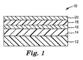
1つの態様では、本開示は、(コ)ポリマーフィルム又は電子デバイスから選択される基材であって、電子デバイスが、更に、有機発光デバイス(OLED)、電気泳動発光デバイス、液晶ディスプレイ、薄膜トランジスタ、光起電デバイス、又はこれらの組み合わせを含む基材と、基材の主表面上のベース(コ)ポリマーと、ベース(コ)ポリマー層上の酸化物層と、酸化物層上の保護(コ)ポリマー層とを含み、保護(コ)ポリマー層が、次式:RS−N(H)−C(O)−O−RA又はRS−O−C(O)−N(H)−RA(RSは、式:−R1−[Si(Yp)(R2)3−p]q(式中、R1は、多価アルキレン、アリーレン、アルカリーレン、又はアラルキレン基であり、前記アルキレン、アリーレン、アルカリーレン、又はアラルキレン基は、任意に、1つ以上のカテナリー酸素原子を含有し、各Yは、加水分解性基であり、R2は、一価のアルキル又はアリール基であり、pは、1、2、又は3であり、qは、1〜5である)のシラン含有基であり、RAは、式:R11−(A)n(式中、R11は、多価アルキレン、アリーレン、アルカリーレン、又はアラルキレン基であり、前記アルキレン、アリーレン、アルカリーレン、又はアラルキレン基は、任意に、1つ以上のカテナリー酸素原子を含有し、Aは、式:X2−C(O)−C(R3)=CH2(式中、X2は、−O、−S、又は−NR3であり、R3は、H又はC1〜C4である)を含む(メタ)アクリル基であり、nは、1〜5である)の(メタ)アクリル基含有基である)の少なくとも1つのウレタン(複数)−(メタ)アクリレート(複数)−シラン前駆体化合物の反応生成物を含む物品について記載する。 In one aspect, the present disclosure is a substrate selected from (co) polymer films or electronic devices, the electronic device further comprising an organic light emitting device (OLED), an electrophoretic light emitting device, a liquid crystal display, a thin film transistor, A substrate comprising a photovoltaic device, or a combination thereof; a base (co) polymer on the major surface of the substrate; an oxide layer on the base (co) polymer layer; and a protection (copolymer) on the oxide layer. ) Polymer layer, wherein the protective (co) polymer layer has the following formula: R S —N (H) —C (O) —O—R A or R S —O—C (O) —N (H) -R A (R S is a formula: -R 1- [Si (Y p ) (R 2 ) 3 -p ] q (wherein R 1 is a polyvalent alkylene, arylene, alkali-ylene, or aralkylene group) Yes, the alkylene, arylene, alkali The len or aralkylene group optionally contains one or more catenary oxygen atoms, each Y is a hydrolyzable group, R 2 is a monovalent alkyl or aryl group, and p is 1 2 or 3, and q is 1 to 5), and R A is a formula: R 11- (A) n (wherein R 11 is a polyvalent alkylene, arylene) , An alkalilene, or an aralkylene group, wherein the alkylene, arylene, alkalilene, or aralkylene group optionally contains one or more catenary oxygen atoms, and A represents the formula: X 2 —C (O) — (Meth) acrylic group comprising C (R 3 ) ═CH 2 , wherein X 2 is —O, —S, or —NR 3 , and R 3 is H or C 1 -C 4. And n is a (meth) acryl group-containing group). An article comprising the reaction product of at least one urethane (s)-(meth) acrylate (s) -silane precursor compound is described.
前述の実施形態のいずれかでは、各加水分解性基Yは、独立して、アルコキシ基、アセテート基、アリールオキシ基、及びハロゲンから選択される。前述の物品の幾つかの特定の例示的な実施形態では、加水分解性基Yのうちの少なくとも幾つかは、アルコキシ基である。 In any of the foregoing embodiments, each hydrolyzable group Y is independently selected from an alkoxy group, an acetate group, an aryloxy group, and a halogen. In some particular exemplary embodiments of the aforementioned articles, at least some of the hydrolyzable groups Y are alkoxy groups.
前述の物品のいずれかの更なる例示的な実施形態では、物品は、ベース(コ)ポリマー層上に、多数の交互に重なる酸化物層及び保護(コ)ポリマー層を含む。前述の物品のいずれかの他の例示的な実施形態では、ベース(コ)ポリマー層は、(メタ)アクリレート平滑化層を含む。 In a further exemplary embodiment of any of the foregoing articles, the article includes a number of alternating oxide layers and protective (co) polymer layers on a base (co) polymer layer. In other exemplary embodiments of any of the foregoing articles, the base (co) polymer layer includes a (meth) acrylate smoothing layer.
前述の物品のいずれかの更なる例示的な実施形態では、酸化物層は、IIA、IIIA、IVA、VA、VIA、VIIA、IB、若しくはIIB族から選択される原子、IIIB、IVB、若しくはVB族の金属、希土類金属、又はこれらの組み合わせ若しくは混合物の少なくとも1つの酸化物、窒化物、炭化物又はホウ化物を含む。前述の物品のいずれかの幾つかの例示的な実施形態では、物品は、保護(コ)ポリマー層に塗布される酸化物層を更に含み、任意に、酸化物層は、ケイ素アルミニウム酸化物を含む。 In further exemplary embodiments of any of the foregoing articles, the oxide layer is an atom selected from the group IIA, IIIA, IVA, VA, VIA, VIIA, IB, or IIB, IIIB, IVB, or VB. At least one oxide, nitride, carbide or boride of a group metal, rare earth metal, or combinations or mixtures thereof. In some exemplary embodiments of any of the foregoing articles, the article further comprises an oxide layer applied to the protective (co) polymer layer, and optionally the oxide layer comprises silicon aluminum oxide. Including.
本開示の幾つかの例示的な実施形態は、複合材バリアアセンブリ、例えば、複合材バリアフィルムを提供する。したがって、複合材バリアフィルムの幾つかの例示的な実施形態では、基材は、可撓性透明(コ)ポリマーフィルムを含み、任意に、基材は、ポリエチレンテレフタレート(PET)、ポリエチレンナフタレート(PEN)、熱安定化PET、熱安定化PEN、ポリオキシメチレン、ポリビニルナフタレン、ポリエーテルエーテルケトン、フルオロ(コ)ポリマー、ポリカーボネート、ポリメチルメタクリレート、ポリα−メチルスチレン、ポリスルホン、ポリフェニレンオキシド、ポリエーテルイミド、ポリエーテルスルホン、ポリアミドイミド、ポリイミド、ポリフタルアミド、又はこれらの組み合わせを含む。更なる態様では、本開示は、光起電デバイス、固体照明デバイス、ディスプレイデバイス、及びこれらの組み合わせから選択される物品において、上記複合材フィルムを用いる方法について記載する。例示的な固体照明デバイスとしては、半導体発光ダイオード(SLED、より一般的にはLEDとして知られている)、有機発光ダイオード(OLED)、又はポリマー発光ダイオード(PLED)が挙げられる。例示的なディスプレイデバイスとしては、液晶ディスプレイ、OLEDディスプレイ、及び量子ドットディスプレイが挙げられる。 Some exemplary embodiments of the present disclosure provide a composite barrier assembly, eg, a composite barrier film. Thus, in some exemplary embodiments of the composite barrier film, the substrate comprises a flexible transparent (co) polymer film, and optionally the substrate is polyethylene terephthalate (PET), polyethylene naphthalate ( PEN), heat-stabilized PET, heat-stabilized PEN, polyoxymethylene, polyvinyl naphthalene, polyether ether ketone, fluoro (co) polymer, polycarbonate, polymethyl methacrylate, poly α-methyl styrene, polysulfone, polyphenylene oxide, polyether Including imide, polyethersulfone, polyamideimide, polyimide, polyphthalamide, or combinations thereof. In a further aspect, the present disclosure describes a method of using the composite film in an article selected from photovoltaic devices, solid state lighting devices, display devices, and combinations thereof. Exemplary solid state lighting devices include semiconductor light emitting diodes (SLEDs, more commonly known as LEDs), organic light emitting diodes (OLEDs), or polymer light emitting diodes (PLEDs). Exemplary display devices include liquid crystal displays, OLED displays, and quantum dot displays.
更なる態様では、本開示は、(a)基材の主表面上にベース(コ)ポリマー層を塗布する工程と、(b)ベース(コ)ポリマー層上に酸化物層を塗布する工程と、(c)酸化物層上に保護(コ)ポリマー層を堆積させる工程とを含み、保護(コ)ポリマー層が、既に記載した通り、式:RS−N(H)−C(O)−O−RA又はRS−O−C(O)−N(H)−RAの前述のウレタン(複数)−(メタ)アクリレート(複数)−シラン前駆体化合物のうちの少なくとも1つの反応生成物として形成される(コ)ポリマーを含む方法について記載する。基材は、(コ)ポリマーフィルム又は電子デバイスから選択され、電子デバイスは、有機発光デバイス(OLED)、電気泳動発光デバイス、液晶ディスプレイ、薄膜トランジスタ、光起電デバイス、又はこれらの組み合わせを更に含む。 In a further aspect, the present disclosure includes (a) applying a base (co) polymer layer on a major surface of a substrate; and (b) applying an oxide layer on the base (co) polymer layer; (C) depositing a protective (co) polymer layer on the oxide layer, wherein the protective (co) polymer layer has the formula R S —N (H) —C (O) as previously described. Reaction of at least one of the aforementioned urethane (s)-(meth) acrylate (s) -silane precursor compounds of —O—R A or R S —O—C (O) —N (H) —R A A method involving a (co) polymer formed as a product is described. The substrate is selected from a (co) polymer film or an electronic device, the electronic device further comprising an organic light emitting device (OLED), an electrophoretic light emitting device, a liquid crystal display, a thin film transistor, a photovoltaic device, or a combination thereof.
方法の幾つかの例示的な実施形態では、少なくとも1つのウレタン(複数)−(メタ)アクリレート(複数)−シラン前駆体化合物は、化学反応して、酸化物層の少なくとも一部上で保護(コ)ポリマー層を形成する。任意で、化学反応は、フリーラジカル重合反応及び加水分解反応から選択される。前述の物品のいずれかでは、各加水分解性基Yは、独立して、アルコキシ基、アセテート基、アリールオキシ基、及びハロゲンから選択される。前述の物品の幾つかの特定の例示的な実施形態では、加水分解性基Yのうちの少なくとも幾つかは、アルコキシ基である。 In some exemplary embodiments of the method, at least one urethane (s)-(meth) acrylate (s) -silane precursor compound is chemically reacted to protect on at least a portion of the oxide layer ( Co) A polymer layer is formed. Optionally, the chemical reaction is selected from a free radical polymerization reaction and a hydrolysis reaction. In any of the foregoing articles, each hydrolyzable group Y is independently selected from an alkoxy group, an acetate group, an aryloxy group, and a halogen. In some particular exemplary embodiments of the aforementioned articles, at least some of the hydrolyzable groups Y are alkoxy groups.
前述の方法のいずれかの幾つかの特定の例示的な実施形態では、工程(a)は、(i)ベース(コ)ポリマー前駆体を蒸発させることと、(ii)蒸発したベース(コ)ポリマー前駆体を基材上で凝結させることと、(iii)蒸発したベース(コ)ポリマー前駆体を硬化させて、ベース(コ)ポリマー層を形成することとを含む。特定のこのような例示的な実施形態では、ベース(コ)ポリマー前駆体は、(メタ)アクリレートモノマーを含む。 In some specific exemplary embodiments of any of the foregoing methods, step (a) comprises (i) evaporating the base (co) polymer precursor and (ii) evaporating the base (co). Condensing the polymer precursor on a substrate and (iii) curing the evaporated base (co) polymer precursor to form a base (co) polymer layer. In certain such exemplary embodiments, the base (co) polymer precursor comprises a (meth) acrylate monomer.
前述の方法のいずれかの特定の具体的で例示的な実施形態では、工程(b)は、ベース(コ)ポリマー層上に酸化物を堆積させて酸化物層を形成することを含む。堆積は、スパッタ堆積、反応性スパッタリング、化学蒸着、又はこれらの組み合わせを用いて行われる。前述の方法のいずれかの幾つかの特定の例示的な実施形態では、工程(b)は、無機ケイ素アルミニウム酸化物をベース(コ)ポリマー層に塗布することを含む。前述の方法のいずれかの更なる例示的な実施形態では、方法は、工程(b)及び(c)を順次繰り返して、ベース(コ)ポリマー層上に多数の交互に重なった保護(コ)ポリマー層及び酸化物層を形成することを更に含む。 In certain specific exemplary embodiments of any of the foregoing methods, step (b) includes depositing an oxide on the base (co) polymer layer to form an oxide layer. Deposition is performed using sputter deposition, reactive sputtering, chemical vapor deposition, or a combination thereof. In some particular exemplary embodiments of any of the foregoing methods, step (b) includes applying inorganic silicon aluminum oxide to the base (co) polymer layer. In a further exemplary embodiment of any of the foregoing methods, the method repeats steps (b) and (c) sequentially to provide a number of alternating protections (co) on the base (co) polymer layer. It further includes forming a polymer layer and an oxide layer.
前述の方法のいずれかの更なる例示的な実施形態では、工程(c)は、液体混合物から少なくとも1つのウレタン(複数)−(メタ)アクリレート(複数)−シラン前駆体化合物と(メタ)アクリレート化合物とを同時に蒸発させるか、又は別々の液体源から少なくとも1つのウレタン(複数)−(メタ)アクリレート(複数)−シラン前駆体化合物と(メタ)アクリレート化合物とを順次蒸発させるか、のうちの少なくとも1つを更に含む。任意に、液体混合物は、約10重量%以下のウレタン(複数)−(メタ)アクリレート(複数)−シラン前駆体化合物を含む。このような方法の更なる例示的な実施形態では、工程(c)は、ウレタン(複数)−(メタ)アクリレート(複数)−シラン前駆体化合物と(メタ)アクリレート化合物とを酸化物層上で同時に凝結させるか、又はウレタン(複数)−(メタ)アクリレート(複数)−シラン前駆体化合物と(メタ)アクリレート化合物とを酸化物層上で順次凝結させるか、のうちの少なくとも1つを更に含む。 In a further exemplary embodiment of any of the foregoing methods, step (c) comprises at least one urethane (s)-(meth) acrylate (s) -silane precursor compound and (meth) acrylate from a liquid mixture. Of evaporating the compounds simultaneously or sequentially evaporating at least one urethane (s)-(meth) acrylates (s) -silane precursor compound and (meth) acrylate compound from separate liquid sources It further includes at least one. Optionally, the liquid mixture comprises up to about 10% by weight of urethane (s)-(meth) acrylate (s) -silane precursor compound. In a further exemplary embodiment of such a method, step (c) comprises urethane (s)-(meth) acrylate (s) -silane precursor compound and (meth) acrylate compound on the oxide layer. It further comprises at least one of coagulating at the same time or coagulating the urethane (s)-(meth) acrylate (s) -silane precursor compound and (meth) acrylate compound sequentially on the oxide layer. .
前述の方法のいずれかの更なる例示的な実施形態では、酸化物層上で保護(コ)ポリマー層を形成するためのウレタン(複数)−(メタ)アクリレート(複数)−シラン前駆体化合物と(メタ)アクリレート化合物との反応は、酸化物層の少なくとも一部上で生じる。 In a further exemplary embodiment of any of the foregoing methods, a urethane (s)-(meth) acrylate (s) -silane precursor compound for forming a protective (co) polymer layer on the oxide layer and The reaction with the (meth) acrylate compound occurs on at least a portion of the oxide layer.
本開示の幾つかの例示的な実施形態は、水分に曝露する用途で用いたときに、改善された耐湿性を示す複合材バリアアセンブリ、物品、又はバリアフィルムを提供する。本開示の例示的な実施形態は、弾性及び可撓性等の優れた機械的特性を示し、更に酸素又は水蒸気の透過率が低いバリアアセンブリ、物品、又はバリアフィルムの形成を可能にすることができる。 Some exemplary embodiments of the present disclosure provide composite barrier assemblies, articles, or barrier films that exhibit improved moisture resistance when used in moisture exposed applications. Exemplary embodiments of the present disclosure exhibit excellent mechanical properties such as elasticity and flexibility, and may allow the formation of barrier assemblies, articles, or barrier films with low oxygen or water vapor transmission. it can.
本開示に係るバリアアセンブリ又はバリアフィルムの例示的な実施形態は、好ましくは、可視光及び赤外光の両方を透過する。また、本開示に係るバリアアセンブリ又はバリアフィルムの例示的な実施形態は、典型的に、可撓性である。本開示に係るバリアアセンブリ又はバリアフィルムの例示的な実施形態は、一般に、多層構造体における熱応力又は収縮から生じる可能性のある、層間剥離又はカールを呈さない。本明細書に開示するバリアアセンブリ又はバリアフィルムの例示的な実施形態の特性は、典型的に、高温及び高湿老化後でさえも維持される。 An exemplary embodiment of a barrier assembly or barrier film according to the present disclosure preferably transmits both visible and infrared light. Also, exemplary embodiments of a barrier assembly or barrier film according to the present disclosure are typically flexible. Exemplary embodiments of barrier assemblies or barrier films according to the present disclosure generally do not exhibit delamination or curl that can result from thermal stress or shrinkage in a multilayer structure. The properties of the exemplary embodiments of the barrier assembly or barrier film disclosed herein are typically maintained even after high temperature and high humidity aging.
以上が本開示の代表的実施形態の様々な態様及び効果の概要である。上述の要約は、本発明の各例示される実施態様又は全ての実施に関して説明することを意図したものではない。更なる特徴及び利点は、以下の実施形態で開示される。図面及び以下の詳細な説明は、本明細書に開示される原理を用いて、特定の好ましい実施形態を更に詳しく例証するものである。 The above is a summary of various aspects and advantages of an exemplary embodiment of the present disclosure. The above summary is not intended to describe each illustrated embodiment or every implementation of the present invention. Additional features and advantages are disclosed in the following embodiments. The drawings and the following detailed description illustrate, in more detail, certain preferred embodiments using the principles disclosed herein.
添付図面は、本明細書の一部に組み込まれ、且つ本明細書を構成するものであり、明細書と共に、本開示の例示的な実施形態の利点及び原理を説明する。
図中、同じ参照番号は、同様の構成要素を指す。本明細書における図は、正確な縮尺で描かれておらず、これら図中に示す構成要素は、選択された特徴を強調するための大きさになっている。 In the figures, the same reference numbers refer to similar components. The figures herein are not drawn to scale, and the components shown in these figures are sized to highlight selected features.
用語
説明及び特許請求の範囲で特定の用語が使用されており、大部分は周知であるが、いくらか説明を必要とする場合がある。本明細書で使用するとき、以下の通り理解すべきである。
Terminology Certain terms are used in the description and in the claims, and are mostly well known, but may require some explanation. As used herein, it should be understood as follows.
単語「a」、「an」、及び「the」は、「少なくとも1つの」と同じ意味で用いられ、記載された構成要素の1つ以上を意味する。 The words “a”, “an”, and “the” are used interchangeably with “at least one” and mean one or more of the listed components.
開示するコーティングされた物品における様々な構成要素の位置について「の上に」、「上の」、「を覆う」、「最上の」、「の下層の」等の配向を表す単語を使用することによって、水平に配置された、上方に面する基材に対する構成要素の相対位置を指す。基材又は物品が、製造中又は製造後に空間内で任意の特定の配向を有しなくてはならないことを意図しない。 Use words representing orientations such as "on top", "on top", "cover over", "top", "under layer" etc. for the location of various components in the disclosed coated article Refers to the relative position of the component with respect to the upwardly facing substrate arranged horizontally. It is not intended that the substrate or article must have any particular orientation in space during or after manufacture.
本開示の物品又はフィルムにおけるバリアアセンブリの基材又は他の構成要素に関する層の位置を説明するための用語「オーバーコーティングされた」を使用することは、基材又は他の構成要素の上にあるが、必ずしも基材又は他の構成要素のいずれかと連続してはいない層を指す。 Using the term “overcoated” to describe the position of a layer relative to a substrate or other component of a barrier assembly in an article or film of the present disclosure is on the substrate or other component Refers to a layer that is not necessarily contiguous with either the substrate or any other component.
2つの無機バリア層に関する(コ)ポリマー層の位置を説明するための用語「により分離されている」を使用することは、無機バリア層の間にあるが、必ずしも無機バリア層のいずれかと連続してはいない(コ)ポリマー層を指す。 The use of the term “separated by” to describe the position of the (co) polymer layer with respect to two inorganic barrier layers is between the inorganic barrier layers, but is not necessarily continuous with any of the inorganic barrier layers. Refers to a (co) polymer layer that is not.
用語「バリアアセンブリ」、「バリアフィルム」、又は「バリア層」は、蒸気、気体、又は芳香の移動に対して不透過性であるように設計されたアセンブリ、フィルム又は層を指す。除外され得る例示的な気体及び蒸気としては、酸素及び/又は水蒸気が挙げられる。 The term “barrier assembly”, “barrier film”, or “barrier layer” refers to an assembly, film or layer that is designed to be impermeable to vapor, gas, or fragrance movement. Exemplary gases and vapors that may be excluded include oxygen and / or water vapor.
モノマー、オリゴマー、又は化合物に関する用語「(メタ)アクリレート」は、アルコールとアクリル酸又はメタクリル酸との反応生成物として形成されるビニル官能性アルキルエステルを意味する。 The term “(meth) acrylate” with respect to a monomer, oligomer or compound means a vinyl functional alkyl ester formed as a reaction product of an alcohol and acrylic acid or methacrylic acid.
用語「ポリマー」又は「(コ)ポリマー」は、ホモポリマー及びコポリマーに加えて、例えば、共押出によって、又は例えばエステル交換を含む反応によって相溶性ブレンド中で形成され得るホモポリマー又はコポリマーを含む。用語「コポリマー」は、ランダム及びブロックコポリマーの両方を含む。 The term “polymer” or “(co) polymer” includes, in addition to homopolymers and copolymers, homopolymers or copolymers that can be formed in a compatible blend, for example, by coextrusion or by a reaction involving, for example, transesterification. The term “copolymer” includes both random and block copolymers.
用語「硬化」は、化学的変化(例えば、水の消費を介する反応)を引き起こして、フィルム層を固化させるか又は粘度を増大させるプロセスを指す。 The term “curing” refers to a process that causes a chemical change (eg, a reaction through consumption of water) to solidify or increase the viscosity of a film layer.
用語「架橋」(コ)ポリマーは、通常は架橋分子又は基を介する共有化学結合によって(コ)ポリマー鎖が互いに結合して、網状(コ)ポリマーを形成する(コ)ポリマーを指す。架橋(コ)ポリマーは、一般的に不溶性であることを特徴とするが、適切な溶媒の存在下で膨潤性である場合もある。 The term “crosslinked” (co) polymer refers to a (co) polymer in which (co) polymer chains are joined together by covalent chemical bonds, usually via a crosslinking molecule or group, to form a network (co) polymer. Crosslinked (co) polymers are generally characterized by insolubility, but may be swellable in the presence of a suitable solvent.
用語「硬化(コ)ポリマー」は、架橋(コ)ポリマーと未架橋(コ)ポリマーとの両方を含む。 The term “cured (co) polymer” includes both crosslinked (co) polymers and uncrosslinked (co) polymers.
用語「Tg」は、薄膜形態ではなくバルクで評価したときの硬化(コ)ポリマーのガラス転移温度を指す。(コ)ポリマーを薄膜形態でしか試験することができない場合、バルク形態のTgは、通常、合理的な精度で推定することができる。バルク形態のTg値は、通常、(コ)ポリマーについての部分移動の開始、及び(コ)ポリマーがガラス状態からゴム状態に変化すると見なすことが出来る変曲点(通常、二次転移)を決定するために、示差走査熱量計(DSC)を使用して、温度に対する熱流の比を評価することにより決定される。また、バルク形態のTg値は、温度及び振動周波数の関数としての(コ)ポリマーの弾性率の変化を測定する動的機械熱分析(DMTA)技術を使用して推測することもできる。 The term “T g ” refers to the glass transition temperature of the cured (co) polymer when evaluated in bulk rather than in thin film form. If the (co) polymer can only be tested in thin film form, the bulk form T g can usually be estimated with reasonable accuracy. The T g value of the bulk form is usually the onset of partial migration for the (co) polymer and the inflection point (usually the second order transition) at which the (co) polymer can be considered to change from the glassy state to the rubbery state. To determine, it is determined by evaluating the ratio of heat flow to temperature using a differential scanning calorimeter (DSC). Bulk form T g values can also be inferred using a dynamic mechanical thermal analysis (DMTA) technique that measures the change in the modulus of the (co) polymer as a function of temperature and vibration frequency.
「可視光透過性」支持体、層、アセンブリ、又はデバイスという用語を使用することは、支持体、層、アセンブリ、又はデバイスの、垂直軸に沿って測定される、スペクトルの可視部分にわたる平均透過率Tvisが、少なくとも約20%であることを意味する。 Using the term “visible light transmissive” support, layer, assembly, or device means the average transmission over the visible portion of the spectrum, measured along the vertical axis, of the support, layer, assembly, or device. It means that the rate T vis is at least about 20%.
用語「金属」は、純金属(即ち、例えば、銀、金、白金等の元素形態の金属)又は金属合金を含む。 The term “metal” includes pure metals (ie, metal in elemental form such as silver, gold, platinum, etc.) or metal alloys.
用語「気相コーティング」又は「蒸着」は、例えば、蒸発させ、次いで、コーティングの前駆材料又はコーティング材料自体を基材表面上に堆積させることによって、蒸気相から基材表面にコーティングを塗布することを意味する。例示的な気相コーティングプロセスとしては、例えば、物理蒸着(PVD)、化学蒸着(CVD)、及びこれらの組み合わせが挙げられる。 The term “vapor phase coating” or “evaporation” refers to applying a coating from a vapor phase to a substrate surface, for example, by evaporating and then depositing the coating precursor or the coating material itself on the substrate surface. Means. Exemplary vapor phase coating processes include, for example, physical vapor deposition (PVD), chemical vapor deposition (CVD), and combinations thereof.
本開示の様々な例示的な実施形態を特に図面に関連して説明する。本開示の例示的な実施形態は、開示の趣旨及び範囲から逸脱することなく、様々な修正及び変更が可能である。したがって、本開示の実施形態は以下に記述する例示的な実施形態に限定されず、請求項及び全てのその等価物に記述される制限によって規制されるものと理解されたい。 Various exemplary embodiments of the present disclosure will be described with particular reference to the drawings. Various modifications and changes can be made to the exemplary embodiments of the present disclosure without departing from the spirit and scope of the disclosure. Accordingly, it is to be understood that the embodiments of the present disclosure are not limited to the exemplary embodiments described below, but are limited by the limitations set forth in the claims and all equivalents thereof.
解決すべき課題の確認
可撓性バリアアセンブリ、コーティング又はバリアフィルムは、成分が水蒸気の進入の影響を受けやすい電子デバイスにとって望ましい。多層バリアアセンブリ、コーティング又はフィルムは、可撓性であり、軽量であり、耐久性であり、且つ低コストで連続ロールツーロール加工が可能であるので、ガラスよりも有利であり得る。
Identifying the problems to be solved Flexible barrier assemblies, coatings or barrier films are desirable for electronic devices whose components are susceptible to the ingress of water vapor. Multi-layer barrier assemblies, coatings or films may be advantageous over glass because they are flexible, lightweight, durable, and capable of continuous roll-to-roll processing at low cost.
多層バリアアセンブリ、コーティング又はフィルムを作製するための公知の方法は、それぞれ、制限を有する。化学蒸着法(CVD及びPECVD)では、基材上に吸着されたときに反応して無機コーティングを形成する気化金属アルコキシド前駆体が形成される。これら方法は、一般的に、堆積速度が低く制限される(したがって、線速度も低い)ので、アルコキシド前駆体の利用効率が低い(アルコキシド蒸気の多くが、コーティングに取り込まれない)。また、CVD法は、多くの場合300〜500℃の範囲の、(コ)ポリマー基材には好適ではない場合のある高い基材温度を更に必要とする。 Each known method for making a multilayer barrier assembly, coating or film has its limitations. In chemical vapor deposition (CVD and PECVD), vaporized metal alkoxide precursors are formed that react when adsorbed onto a substrate to form an inorganic coating. These methods generally have low deposition rates (and therefore low linear velocities), so the utilization efficiency of the alkoxide precursor is low (much of the alkoxide vapor is not incorporated into the coating). Also, the CVD method further requires high substrate temperatures, which are often in the range of 300-500 ° C., which may not be suitable for (co) polymer substrates.
固体材料の熱蒸発(例えば、抵抗加熱又は電子線加熱)等の真空法でも、金属酸化物の堆積速度は低くなる。熱蒸発は、均一性の高いコーティング(例えば、光学コーティング)を必要とするロール幅のウェブ用途用にスケールアップすることが困難であり、高品質のコーティングを得るために基材の加熱を必要とすることがある。更に蒸発/昇華法では、コーティングの品質を向上させるために、一般に小さい面積に限定されるイオン支援を必要とすることがある。 Even in a vacuum method such as thermal evaporation of a solid material (for example, resistance heating or electron beam heating), the metal oxide deposition rate is low. Thermal evaporation is difficult to scale up for roll-width web applications that require highly uniform coatings (eg, optical coatings) and requires heating of the substrate to obtain a high quality coating There are things to do. Further, evaporation / sublimation methods may require ion assistance, which is generally limited to a small area, in order to improve the quality of the coating.
金属酸化物層を形成させるために、スパッタリングも用いられている。バリア酸化物層を形成するために用いられるスパッタプロセスの堆積エネルギーは、一般的に高いが、(メタ)アクリレート層の堆積に関与するエネルギーは、一般的に低い。その結果、(メタ)アクリレート層は、典型的に、その下の層、例えば、無機バリア酸化物副層との接着特性がそれほど良好ではない。保護(メタ)アクリレート層のバリア酸化物に対する接着レベルを高めるために、亜酸化ケイ素のスパッタ薄層が有用であることが当該技術分野において知られている。亜酸化ケイ素層がスタックに含まれてない場合、保護(メタ)アクリレート層は、バリア酸化物に対する初期接着力が低い。亜酸化ケイ素層スパッタプロセスは、接着性能を維持するために正確な出力及び気流設定を用いて実施しなければならない。この堆積プロセスは、従来より、ノイズの影響を受けやすく、それによって、保護(メタ)アクリレート層の接着力が変化したり低下したりする。したがって、接着力の堅牢性を高め、且つプロセスの複雑さを低減するために、最終バリア構造体における亜酸化ケイ素層の必要性をなくすことが望ましい。 Sputtering is also used to form the metal oxide layer. The deposition energy of the sputter process used to form the barrier oxide layer is generally high, but the energy involved in the deposition of the (meth) acrylate layer is generally low. As a result, (meth) acrylate layers typically do not have very good adhesion properties with the underlying layers, eg, inorganic barrier oxide sublayers. It is known in the art that sputtered thin layers of silicon oxide are useful for increasing the level of adhesion of the protective (meth) acrylate layer to the barrier oxide. If a silicon suboxide layer is not included in the stack, the protective (meth) acrylate layer has a low initial adhesion to the barrier oxide. The silicon oxide layer sputter process must be performed with accurate power and airflow settings to maintain adhesion performance. This deposition process is conventionally sensitive to noise, which changes or reduces the adhesion of the protective (meth) acrylate layer. Accordingly, it is desirable to eliminate the need for a silicon suboxide layer in the final barrier structure to increase adhesion robustness and reduce process complexity.
標準的なバリアスタックの「堆積したとき」の接着力が最初は許容可能である場合でさえも、亜酸化物及び保護(メタ)アクリレート層は、85℃/相対湿度(RH)85%の促進老化条件に曝露したときには脆弱であることが示されている。この層間脆弱性により、保護を意図するデバイスから複合材フィルムが早期に層間剥離することがある。多層構造体は、85℃及び85% RHにおいて老化させたとき、初期接着レベルを改善し、維持することが望ましい。 Even when the “as deposited” adhesion of a standard barrier stack is initially acceptable, the suboxide and protective (meth) acrylate layer promotes 85 ° C./85% relative humidity (RH) It has been shown to be fragile when exposed to aging conditions. Due to this interlaminar vulnerability, the composite film may delaminate early from the device intended for protection. It is desirable that multilayer structures improve and maintain initial adhesion levels when aged at 85 ° C. and 85% RH.
この問題点に対する解決策の1つは、特定の元素(例えば、クロム、ジルコニウム、チタン、ケイ素等)の「結合」層と呼ばれるものを使用することであり、これは、多くの場合、元素として、又は少量の酸素の存在下で、材料の単一層、即ち、薄層としてスパッタ堆積される。次いで、結合層の元素は、基材層である酸化物と、キャッピング層である(コ)ポリマーの両方と化学結合を形成できる。 One solution to this problem is to use what are called “bonded” layers of certain elements (eg, chromium, zirconium, titanium, silicon, etc.), which are often used as elements Or sputter deposited as a single layer of material, ie, a thin layer, in the presence of a small amount of oxygen. The elements of the tie layer can then form chemical bonds with both the base layer oxide and the capping layer (co) polymer.
一般に、結合層は、異なる材料の層同士を接着させるために真空コーティング業界で使用されている。層の堆積に用いられるプロセスは、適切な結合層原子の層濃度を得るために微調整が必要なことが多い。堆積は、真空圧の変動、ガス放出、及び他のプロセスからの交差汚染等、真空コーティングプロセスにおけるわずかな変化の影響を受ける場合があり、製品の接着レベルの変動の原因となる。更に、結合層は、水蒸気への曝露後に初期の接着レベルを保持していないことが多い。複合材フィルムにおける接着力の改善には、より強固な解決策が望まれる。 In general, tie layers are used in the vacuum coating industry to bond layers of different materials together. The process used for layer deposition often requires fine tuning to obtain the appropriate tie layer atom concentration. Deposition can be affected by minor changes in the vacuum coating process, such as fluctuations in vacuum pressure, outgassing, and cross-contamination from other processes, causing fluctuations in product adhesion levels. Furthermore, the tie layer often does not retain the initial adhesion level after exposure to water vapor. A stronger solution is desired to improve the adhesion in composite films.
課題を解決するための手段の発見
驚くべきことに、以下に更に記載する少なくとも1つのウレタン(複数)−(メタ)アクリレート(複数)−シラン前駆体化合物の反応生成物を含む保護(コ)ポリマー層を含む物品又はフィルムにおける複合材バリアアセンブリは、物品又はフィルムにおける多層複合材バリアアセンブリの接着力及び水分バリア性能を改善することが見出された。物品又はフィルムにおけるこれら多層複合材バリアフィルムは、ガラス封入材料の可撓性代替物として、光電池、ディスプレイ、照明、及び電子デバイス市場において応用性が高い。
Discovery of means for solving the problem Surprisingly, a protected (co) polymer comprising the reaction product of at least one urethane (s)-(meth) acrylates (s) -silane precursor compound as further described below. It has been found that a composite barrier assembly in an article or film comprising a layer improves the adhesion and moisture barrier performance of the multilayer composite barrier assembly in the article or film. These multilayer composite barrier films in articles or films have high applicability in the photovoltaic, display, lighting, and electronic device markets as flexible replacements for glass encapsulating materials.
本開示の例示的な実施形態では、物品又はフィルムにおける改善されたバリアアセンブリを得るための所望の技術的効果及び技術的課題に対する解決策は、幾つかの例示的な実施形態では、以下を達成するために、物品又はフィルムにおける多層複合材バリアアセンブリに対して保護(コ)ポリマー層を(例えば、気相コーティングにより)塗布する方法において用いられる組成物を化学的に修飾することによって得られた:
1)無機酸化物表面との堅牢な化学結合を得る、
2)(共)重合を通して(メタ)アクリレートコーティングに対する堅牢な化学結合を得る、及び
3)バルク(メタ)アクリレート材料と同時に蒸発することができるように、修飾分子の物性(例えば、沸点、蒸気圧等)のうちの幾つかを維持する。
In an exemplary embodiment of the present disclosure, a solution to a desired technical effect and technical problem to obtain an improved barrier assembly in an article or film, in some exemplary embodiments, achieves the following: Obtained by chemically modifying a composition used in a method of applying a protective (co) polymer layer (eg, by vapor phase coating) to a multilayer composite barrier assembly in an article or film :
1) A strong chemical bond with the inorganic oxide surface is obtained.
2) to obtain a robust chemical bond to the (meth) acrylate coating through (co) polymerization, and 3) physical properties of the modified molecule (eg, boiling point, vapor pressure) so that it can evaporate simultaneously with the bulk (meth) acrylate material Etc.).
多層複合材バリアアセンブリ又はフィルム
したがって、例示的な実施形態では、本開示は、物品又はフィルムにおける多層複合材バリアアセンブリであって、
基材と、基材の主表面上のベース(コ)ポリマー層と、ベース(コ)ポリマー層上の酸化物層と、酸化物層上の保護(コ)ポリマー層とを含み、保護(コ)ポリマー層が、以下に更に記載する通り、式:RS−N(H)−C(O)−O−RA又はRS−O−C(O)−N(H)−RAの少なくとも1つのウレタン(複数)−(メタ)アクリレート(複数)−シラン前駆体化合物の反応生成物を含む、アセンブリについて記載する。
Accordingly, in an exemplary embodiment, the present disclosure provides a multilayer composite barrier assembly in an article or film comprising:
A protective (co) polymer layer comprising a substrate, a base (co) polymer layer on the main surface of the substrate, an oxide layer on the base (co) polymer layer, and a protective (co) polymer layer on the oxide layer. ) The polymer layer is of the formula R S —N (H) —C (O) —O—R A or R S —O—C (O) —N (H) —R A as described further below. An assembly comprising a reaction product of at least one urethane (s)-(meth) acrylate (s) -silane precursor compound is described.
任意の無機層(好ましくは、酸化物層)を、保護(コ)ポリマー層上に塗布してもよい。本明細書において好ましい無機層は、ケイ素アルミニウム酸化物又はインジウムスズ酸化物のうちの少なくとも1つを含む。 Any inorganic layer (preferably an oxide layer) may be applied over the protective (co) polymer layer. Preferred inorganic layers herein include at least one of silicon aluminum oxide or indium tin oxide.
図を参照すると、図1は、光起電デバイス11に適用された、単一のダイアドを含む耐湿性コーティングを有する物品又はフィルム10における例示的なバリアアセンブリの図である。フィルム10は、基材12、ベース(コ)ポリマー層14、酸化物層16、本明細書に記載する少なくとも1つのウレタン(複数)−(メタ)アクリレート(複数)−シラン前駆体化合物の反応生成物を含む保護(コ)ポリマー層18、及び任意の酸化物層20の順で配置される層を含む。酸化物層16及び保護(コ)ポリマー層18は、一緒にダイアドを形成し、図示されているダイアドは1つだけであるが、フィルム10は、基材10と最上ダイアドとの間に、交互に重なった酸化物層16及び保護(コ)ポリマー層18の更なるダイアドを含んでもよい。
Referring to the drawings, FIG. 1 is an illustration of an exemplary barrier assembly in an article or
特定の例示的な実施形態では、物品又はフィルムにおける複合材バリアアセンブリは、ベース(コ)ポリマー層上に、複数の交互に重なった酸化物層及び保護(コ)ポリマー層を含む。酸化物層及び保護(コ)ポリマー層は、一緒に「ダイアド」を形成し、1つの例示的な実施形態では、物品又はフィルムにおけるバリアアセンブリは、1超のダイアドを含んで、物品又はフィルムにおける多層バリアアセンブリを形成してもよい。物品又はフィルムにおける多層バリアアセンブリ(即ち、1超のダイアドを含む)における酸化物層及び/又は保護(コ)ポリマー層は、それぞれ、同じであってもよく、又は異なっていてもよい。任意の無機層(好ましくは、酸化物層である)は、複数の交互に重なった層、即ちダイアド上に塗布してよい。 In certain exemplary embodiments, a composite barrier assembly in an article or film includes a plurality of alternating oxide layers and protective (co) polymer layers on a base (co) polymer layer. The oxide layer and the protective (co) polymer layer together form a “dyad”, and in one exemplary embodiment, the barrier assembly in the article or film comprises more than one dyad, in the article or film. A multilayer barrier assembly may be formed. The oxide layer and / or protective (co) polymer layer in the multilayer barrier assembly (ie, comprising more than one dyad) in the article or film may each be the same or different. An optional inorganic layer (preferably an oxide layer) may be applied over a plurality of alternating layers or dyads.
幾つかの例示的な実施形態では、少なくとも1つのウレタン(複数)−(メタ)アクリレート(複数)−シラン前駆体化合物の反応生成物を含む保護(コ)ポリマー層18は、フィルム10の耐湿性、及び保護(コ)ポリマー層18の下層の酸化物層に体する引き剥がし強度接着力を改善し、以下に更に説明する通り、更なるバリアスタック層内の接着力及び層間剥離耐性の改善を導く。物品又はフィルム10におけるバリアアセンブリにおいて用いるための本明細書において好ましい材料は、以下及び実施例において更に特定される。
In some exemplary embodiments, the protective (co) polymer layer 18 comprising the reaction product of at least one urethane (s)-(meth) acrylate (s) -silane precursor compound is used to protect the moisture resistance of the
保護(コ)ポリマー層
本開示は、例えば、電子デバイスをパッケージングするためのパッケージング材料として用いるとき、酸素及び/又は水蒸気バリア透過率の低減において有用な物品又はフィルムにおけるバリアアセンブリにおいて(即ち、バリアフィルムとして)用いられる保護(コ)ポリマー層について記載する。各保護(コ)ポリマー層は、その製造において、以下に更に記載する通り、ウレタン(複数)−(メタ)アクリレート(複数)−シラン前駆体化合物として本明細書に記載される物質の少なくとも1つの組成物を含み、その反応生成物は、(コ)ポリマーを形成する。特に、本明細書に記載するウレタン(複数)−(メタ)アクリレート(複数)−シラン前駆体化合物は、幾つかの例示的な実施形態では、物品又はフィルムにおける多層バリアアセンブリの層間接着力を改善するためのカップリング剤として有用である。
Protective (Co) polymer Layer The present disclosure is used in barrier assemblies in articles or films useful in reducing oxygen and / or water vapor barrier permeability when used, for example, as a packaging material for packaging electronic devices (ie, The protective (co) polymer layer used as the barrier film is described. Each protective (co) polymer layer in its manufacture is at least one of the materials described herein as urethane (s)-(meth) acrylates (s) -silane precursor compounds, as further described below. The reaction product, including the composition, forms a (co) polymer. In particular, the urethane (s)-(meth) acrylate (s) -silane precursor compounds described herein improve the interlayer adhesion of multilayer barrier assemblies in articles or films in some exemplary embodiments. It is useful as a coupling agent.
複合材バリアアセンブリ又はバリアフィルム材料
本開示は、以下に更に記載する通り、少なくとも1つのウレタン(複数)−(メタ)アクリレート(複数)−シラン前駆体化合物の反応生成物を含む保護(コ)ポリマー層について記載する。
COMPOSITE BARRIER ASSEMBLY OR BARRIER FILM MATERIAL This disclosure relates to a protected (co) polymer comprising a reaction product of at least one urethane (s)-(meth) acrylates (s) -silane precursor compound, as further described below. Describe the layer.
ウレタン(複数)−アクリレート−シラン前駆体化合物
例示的な実施形態では、本開示は、式:RS−N(H)−C(O)−O−RA又はRS−O−C(O)−N(H)−RAの少なくとも1つのウレタン(複数)−(メタ)アクリレート(複数)−シラン前駆体化合物を含む物質の組成物を使用する。RSは、式:−R1−[Si(Yp)(R2)3−p]q(式中、R1は、多価アルキレン、アリーレン、アルカリーレン、又はアラルキレン基であり、前記アルキレン、アリーレン、アルカリーレン、又はアラルキレン基は、任意に、1つ以上のカテナリー酸素原子を含有し、各Yは、加水分解性基であり、R2は、一価のアルキル又はアリール基であり、pは、1、2、又は3であり、qは、1〜5である)のシラン含有基である。RAは、式:R11−(A)n(式中、R11は、多価アルキレン、アリーレン、アルカリーレン、又はアラルキレン基であり、前記アルキレン、アリーレン、アルカリーレン、又はアラルキレン基は、任意に、1つ以上のカテナリー酸素原子を含有し、Aは、式:X2−C(O)−C(R3)=CH2(式中、X2は、−O、−S、又は−NR3であり、R3は、H又はC1〜C4である)を含む(メタ)アクリル基であり、nは、1〜5である)の(メタ)アクリル基含有基である。
Urethane (s) -acrylate-silane precursor compound In an exemplary embodiment, the disclosure provides a compound of the formula: R S —N (H) —C (O) —O—R A or R S —O—C (O A composition of matter comprising at least one urethane (s)-(meth) acrylate (s) -silane precursor compound of) -N (H) -R A is used. R S is represented by the formula: —R 1 — [Si (Y p ) (R 2 ) 3−p ] q (wherein R 1 is a polyvalent alkylene, arylene, alkali-ylene, or aralkylene group, and the alkylene , An arylene, alkali-lene, or aralkylene group optionally contains one or more catenary oxygen atoms, each Y is a hydrolyzable group, and R 2 is a monovalent alkyl or aryl group; p is 1, 2, or 3, and q is 1-5). R A is a formula: R 11- (A) n (wherein R 11 is a polyvalent alkylene, arylene, alkali-ylene, or aralkylene group, and the alkylene, arylene, alkali-ylene, or aralkylene group is optional. And containing one or more catenary oxygen atoms, A is represented by the formula: X 2 —C (O) —C (R 3 ) ═CH 2 , wherein X 2 is —O, —S, or — It is NR 3 and R 3 is H or C 1 to C 4 ), and is a (meth) acryl group-containing group.
前述の実施形態のいずれかでは、各加水分解性基Yは、独立して、アルコキシ基、アセテート基、アリールオキシ基、及びハロゲンから選択される。前述の物品の幾つかの特定の例示的な実施形態では、加水分解性基Yのうちの少なくとも幾つかは、アルコキシ基である。 In any of the foregoing embodiments, each hydrolyzable group Y is independently selected from an alkoxy group, an acetate group, an aryloxy group, and a halogen. In some particular exemplary embodiments of the aforementioned articles, at least some of the hydrolyzable groups Y are alkoxy groups.
前述の種類のウレタン(複数)−(メタ)アクリレート−シラン前駆体化合物は、公知であり、且つ典型的に、モノアルコール官能基を有する(メタ)アクリル化材料と、未希釈の又は溶媒中のモノイソシアネート官能基を有するシラン化合物との反応によって合成され、多くの場合、反応を促進するためにスズ化合物等の触媒を用いる。あるいは、これら材料は、同様の条件下で、モノイソシアネート官能基を有する(メタ)アクリル化材料と、モノアルコール官能基を有するシラン化合物との反応によって作製することができる。 Urethane (s)-(meth) acrylate-silane precursor compounds of the aforementioned type are known and typically (meth) acrylated materials having monoalcohol functionality and undiluted or in a solvent It is synthesized by a reaction with a silane compound having a monoisocyanate functional group, and in many cases, a catalyst such as a tin compound is used to accelerate the reaction. Alternatively, these materials can be made by reacting a (meth) acrylated material having a monoisocyanate functional group with a silane compound having a monoalcohol functional group under similar conditions.
アルコール官能基を有する(メタ)アクリル化材料の例としては、ヒドロキシエチルアクリレート、ヒドロキシプロピルアクリレート、ヒドロキシブチルアクリレート、ヒドロキシエチルメタクリレート、ヒドロキシプロピルメタクリレート、ヒドロキシブチルメタクリレート、1,3−ジメタクリルオキシ−2−ヒドロキシ−プロパン、1−アクリルオキシ−3−メタクリルオキシ−2−ヒドロキシ−プロパン、トリメチロールプロパンジアクリレート、ペンタエリスリトールトリアクリレートが挙げられる。 Examples of (meth) acrylated materials having alcohol functional groups include hydroxyethyl acrylate, hydroxypropyl acrylate, hydroxybutyl acrylate, hydroxyethyl methacrylate, hydroxypropyl methacrylate, hydroxybutyl methacrylate, 1,3-dimethacryloxy-2- Examples include hydroxy-propane, 1-acryloxy-3-methacryloxy-2-hydroxy-propane, trimethylolpropane diacrylate, and pentaerythritol triacrylate.
イソシアネート官能基を有するシラン化合物の例としては、3−トリエトキシシリルプロピルイソシアネート、及び3−トリメトキシシリルプロピルイソシアネートが挙げられる。 Examples of the silane compound having an isocyanate functional group include 3-triethoxysilylpropyl isocyanate and 3-trimethoxysilylpropyl isocyanate.
幾つかの典型的なモノイソシアネート官能基を有する(メタ)アクリル化材料としては、3−イソシアナトエチルメタクリレート及び3−イソシアナトエチルメタクリレートが挙げられる。モノアルコール官能基を有するシランの例としては、N−(ヒドロキシエチル)−N−メチルアミノプロピルトリメトキシシラン、及び3−ヒドロキシ−ブチルトリメトキシシランが挙げられる。 Some typical (meth) acrylated materials having monoisocyanate functionality include 3-isocyanatoethyl methacrylate and 3-isocyanatoethyl methacrylate. Examples of silanes having a monoalcohol functional group include N- (hydroxyethyl) -N-methylaminopropyltrimethoxysilane and 3-hydroxy-butyltrimethoxysilane.
ウレタンの典型的な調製は、Polyurethanes:Chemistry and Technology,Saunders and Frisch,Interscience Publishers(New York,1963(Part I)及び1964(Part II)に見出すことができる。 Typical preparations of urethanes can be found in Polyurethanes: Chemistry and Technology, Saunders and Frisch, Interscience Publishers (New York, 1963 (Part I) and 1964 (Part II)).
ウレタン(複数)−(メタ)アクリレート(複数)−シラン前駆体化合物の分子量は、真空プロセス条件における十分な蒸気圧が、蒸発を実施し、次いで、凝結させて、液体薄膜を形成するのに有効である範囲である。分子量は、好ましくは、約2,000Da未満、より好ましくは1,000Da未満、更により好ましくは500Da未満である。 The molecular weight of the urethane (s)-(meth) acrylates (s) -silane precursor compound is sufficient to form a liquid film, with sufficient vapor pressure under vacuum process conditions to perform evaporation and then condense Is a range. The molecular weight is preferably less than about 2,000 Da, more preferably less than 1,000 Da, and even more preferably less than 500 Da.
好ましくは、ウレタン(複数)−(メタ)アクリレート(複数)−シラン前駆体化合物は、気相コーティングされた混合物の20重量%以下、より好ましくは、19重量%、18重量%、17重量%、16重量%、15重量%、14重量%、13重量%、12重量%、11重量%以下、更により好ましくは、蒸着した混合物の10重量%、9重量%、8重量%、7重量%、6重量%、5重量%、4重量%、3重量%、2重量%、又は更には1重量%で存在する。 Preferably, the urethane (s)-(meth) acrylate (s) -silane precursor compound is 20 wt% or less of the gas phase coated mixture, more preferably 19 wt%, 18 wt%, 17 wt%, 16 wt%, 15 wt%, 14 wt%, 13 wt%, 12 wt%, 11 wt% or less, even more preferably 10 wt%, 9 wt%, 8 wt%, 7 wt% of the deposited mixture, It is present at 6%, 5%, 4%, 3%, 2%, or even 1% by weight.
基材
基材12は、(コ)ポリマーフィルム又は電子デバイスから選択され、この電子デバイスは、有機発光ダイオード(OLED)、電気泳動発光デバイス、液晶ディスプレイ、薄膜トランジスタ、光起電デバイス、又はこれらの組み合わせを更に含む。
Substrate The
典型的に、電子デバイス基材は、感湿性電子デバイスである。感湿性電子デバイスは、例えば、有機、無機、又はハイブリッド有機/無機半導体デバイスであってよく、例えば、銅インジウムガリウム(ジ)セレン(CIGS)太陽電池等の光起電デバイス;有機発光ディスプレイ(OLED)、エレクトロクロミックディスプレイ、電気泳動ディスプレイ、又は液晶ディスプレイ(LCD)(例えば、量子ドットLCDディスプレイ)等のディスプレイデバイス;OLED又は他のエレクトロルミネセント固体照明デバイス、又はこれらの組み合わせ等が挙げられる。 Typically, the electronic device substrate is a moisture sensitive electronic device. The moisture sensitive electronic device may be, for example, an organic, inorganic, or hybrid organic / inorganic semiconductor device, such as a photovoltaic device such as a copper indium gallium (di) selenium (CIGS) solar cell; an organic light emitting display (OLED) ), An electrochromic display, an electrophoretic display, or a liquid crystal display (LCD) (eg, a quantum dot LCD display); an OLED or other electroluminescent solid state lighting device, or a combination thereof.
幾つかの例示的な実施形態では、基材12は、可撓性光透過性(コ)ポリマーフィルム等の可撓性可視光透過性基材であってよい。本明細書において好ましい1つの例示的な実施形態では、基材は、実質的に透明であり、550nmにおいて少なくとも約50%、60%、70%、80%、90%、又は更には最高約100%の可視光透過率を有し得る。
In some exemplary embodiments, the
例示的な可撓性光透過性基材としては、熱可塑性(コ)ポリマーフィルム(例えば、ポリエステル、ポリアクリレート(例えば、ポリメチルメタクリレート)、ポリカーボネート、ポリプロピレン、高又は低密度ポリエチレン、ポリスルホン、ポリエーテルスルホン、ポリウレタン、ポリアミド、ポリビニルブチラール、ポリ塩化ビニル、フルオロ(コ)ポリマー(例えば、ポリビニリデンジフルオリド及びポリテトラフルオロエチレン)、ポリエチレンスルフィド、及び熱硬化性フィルム(例えば、エポキシ、セルロース誘導体、ポリイミド、ポリイミドベンズオキサゾール、及びポリベンズオキサゾール)が挙げられる。 Exemplary flexible light transmissive substrates include thermoplastic (co) polymer films (eg, polyester, polyacrylate (eg, polymethyl methacrylate), polycarbonate, polypropylene, high or low density polyethylene, polysulfone, polyether. Sulfone, polyurethane, polyamide, polyvinyl butyral, polyvinyl chloride, fluoro (co) polymers (eg, polyvinylidene difluoride and polytetrafluoroethylene), polyethylene sulfide, and thermosetting films (eg, epoxy, cellulose derivatives, polyimide, Polyimide benzoxazole and polybenzoxazole).
本明細書において好ましい(コ)ポリマーフィルムは、ポチレンテレフタレート(PET)、ポリエチレンナフタレート(PEN)、熱安定化PET、熱安定化PEN、ポリオキシメチレン、ポリビニルナフタレン、ポリエーテルエーテルケトン、フルオロ(コ)ポリマー、ポリカーボネート、ポリメチルメタクリレート、ポリα−メチルスチレン、ポリスルホン、ポリフェニレンオキシド、ポリエーテルイミド、ポリエーテルスルホン、ポリアミドイミド、ポリイミド、ポリフタルアミド、又はこれらの組み合わせを含む。 Preferred (co) polymer films herein are polyethylene terephthalate (PET), polyethylene naphthalate (PEN), thermally stabilized PET, thermally stabilized PEN, polyoxymethylene, polyvinyl naphthalene, polyetheretherketone, fluoro ( Co) polymer, polycarbonate, polymethyl methacrylate, poly alpha-methyl styrene, polysulfone, polyphenylene oxide, polyetherimide, polyethersulfone, polyamideimide, polyimide, polyphthalamide, or combinations thereof.
幾つかの例示的な実施形態では、基材は、例えば、米国特許出願公開第2004/0032658 A1号に記載されているもの等の多層光学フィルム(「MOF」)であってもよい。1つの例示的な実施形態では、フィルムは、PETを含む基材上で調製してもよい。 In some exemplary embodiments, the substrate may be a multilayer optical film (“MOF”) such as, for example, those described in US Patent Application Publication No. 2004/0032658 A1. In one exemplary embodiment, the film may be prepared on a substrate comprising PET.
(コ)ポリマーフィルムは、熱硬化、張力下でのアニーリング、又は(コ)ポリマーフィルムが拘束されていない場合に少なくとも熱安定化温度まで収縮を抑制する他の技術を使用して熱安定化してもよい。 The (co) polymer film may be thermally stabilized using thermosetting, annealing under tension, or other techniques that inhibit shrinkage to at least the heat stabilization temperature when the (co) polymer film is unconstrained. Also good.
基材は、例えば、約0.01〜約1mm等の様々な厚さを有し得る。しかし、例えば、自己支持型物品が望しい場合等では、基材は、これよりもかなり厚くてもよい。また、このような物品は、可撓性基材を使用して作製された開示するフィルムを、より厚い不撓性又は低可撓性の補助的支持体に積層、又は別の方法で接合させることによっても便利に製造することができる。 The substrate can have various thicknesses, for example, from about 0.01 to about 1 mm. However, for example, where a self-supporting article is desired, the substrate may be much thicker than this. Also, such articles can be made by laminating or otherwise bonding a disclosed film made using a flexible substrate to a thicker, non-flexible or low-flexibility auxiliary support. Can also be manufactured conveniently.
ベース(コ)ポリマー層
図1を参照すると、ベース(コ)ポリマー層14は、薄膜で堆積させるのに好適な任意の(コ)ポリマーを含んでよい。1つの態様では、例えば、ベース(コ)ポリマー層14は、例えば、ウレタンアクリレート、イソボルニルアクリレート、ジペンタエリスリトールペンタアクリレート、エポキシアクリレート、スチレンとブレンドされたエポキシアクリレート、ジ−トリメチロールプロパンテトラアクリレート、ジエチレングリコールジアクリレート、1,3−ブチレングリコールジアクリレート、ペンタアクリレートエステル、ペンタエリトリトールテトラアクリレート、ペンタエリトリトールトリアクリレート、エトキシル化(3)トリメチロールプロパントリアクリレート、エトキシル化(3)トリメチロールプロパントリアクリレート、アルコキシル化三官能性アクリレートエステル、ジプロピレングリコールジアクリレート、ネオペンチルグリコールジアクリレート、エトキシル化(4)ビスフェノールジメタクリレート、シクロヘキサンジメタノールジアクリレートエステル、イソボルニルメタクリレート、環状ジアクリレート及びトリス(2−ヒドロキシエチル)イソシアヌレートトリアクリレート等のアクリレート又はメタクリレート、前述のメタクリレートのアクリレート、並びに前述のアクリレートのメタクリレートを含む様々な前駆体、例えば、(メタ)アクリレートモノマー及び/又はオリゴマーから形成されてもよい。好ましくは、ベース(コ)コポリマー前駆体は、(メタ)アクリレートモノマーを含む。
Base (Co) polymer Layer Referring to FIG. 1, the base (co)
ベース(コ)ポリマー層14は、モノマー又はオリゴマーの層を基材に塗布し、層を架橋させて、例えば放射線架橋可能なモノマーのフラッシュ蒸発及び蒸着によってその場で(コ)ポリマーを形成し、次いで、例えば、電子ビーム装置、UV光源、放電装置、又は他の好適なデバイスを使用して架橋させることによって形成することができる。コーティング効率は、基材を冷却することによって改善することができる。
The base (co)
また、モノマー又はオリゴマーは、上記の通り、ロールコーティング(例えば、グラビアロールコーティング)、又はスプレーコーティング(例えば、静電気スプレーコーティング)等の従来のコーティング方法を使用して基材12に塗布し、次いで、架橋させてもよい。また、ベース(コ)ポリマー層14は、溶媒中にオリゴマー又は(コ)ポリマーを含有する層を塗布し、このように塗布された層を乾燥させて溶媒を除去することによって形成してもよい。場合によっては、プラズマ促進化学蒸着(PECVD)を使用してもよい。
The monomer or oligomer is also applied to the
最も好ましくは、ベース(コ)ポリマー層14は、例えば、以下に記載の通り、フラッシュ蒸発及び蒸着後にその場で架橋させることによって形成される:米国特許第4,696,719号(Bischoff)、同第4,722,515号(Ham)、同第4,842,893号(Yializisら)、同第4,954,371号(Yializis)、同第5,018,048号(Shawら)、同第5,032,461号(Shawら)、同第5,097,800号(Shawら)、同第5,125,138号(Shawら)、同第5,440,446号(Shawら)、同第5,547,908号(Furuzawaら)、同第6,045,864号(Lyonsら)、同第6,231,939号(Shawら)、及び同第6,214,422号(Yializis);国際公開第00/26973号(Delta V Technologies,Inc.);D.G.Shaw and M.G.Langlois、「A New Vapor Deposition Process for Coating Paper and (co)polymer Webs」、6th International Vacuum Coating Conference(1992);D.G.Shaw and M.G.Langlois、「A New High Speed Process for Vapor Depositing Acrylate Thin Films:An Update」、Society of Vacuum Coaters 36th Annual Technical Conference Proceedings(1993);D.G.Shaw and M.G.Langlois、「Use of Vapor Deposited Acrylate Coatings to Improve the Barrier Properties of Metallized Film」、Society of Vacuum Coaters 37th Annual Technical Conference Proceedings(1994);D.G.Shaw,M.Roehrig,M.G.Langlois and C.Sheehan、「Use of Evaporated Acrylate Coatings to Smooth the Surface of Polyester and Polypropylene Film Substrates」、RadTech(1996);J.Affinito,P.Martin,M.Gross,C.Coronado and E.Greenwell、「Vacuum Deposited Polymer/Metal Multilayer Films for Optical Application」、Thin Solid Films 270,43〜48(1995);及びJ.D.Affinito,M.E.Gross,C.A.Coronado,G.L.Graff,E.N.Greenwell and P.M.Martin,「Polymer−Oxide Transparent Barrier Layers」,Society of Vacuum Coaters 39th Annual Technical Conference Proceedings(1996)。
Most preferably, the base (co)
幾つかの例示的な実施形態では、ベース(コ)ポリマー層14(また、各酸化物層16及び保護(コ)ポリマー層18)の平滑性及び連続性、並びに下層の基材又は層に対する接着力は、適切な前処理によって高めることができる。好適な前処理レジメンの例としては、好適な反応性又は非反応性雰囲気の存在下での放電(例えば、プラズマ、グロー放電、コロナ放電、誘電体バリア放電又は大気圧放電)、化学的前処理又は火炎前処理が挙げられる。これら前処理は、続いて塗布される(コ)ポリマー(又は無機)層の形成に対する、下層の層の表面の受容力を高めるのに役立つ。プラズマ前処理が特に有用であり得る。
In some exemplary embodiments, the smoothness and continuity of the base (co) polymer layer 14 (also each
幾つかの例示的な実施形態では、接着力を改善するために、ベース(コ)ポリマー層14とは異なる組成を有し得る別個の接着促進層を、基材又は下層の層上に用いてもよい。接着促進層は、例えば、別個の(コ)ポリマー層であってもよく、又は金属、金属酸化物、金属窒化物若しくは金属酸窒化物の層等の金属含有層であってもよい。接着促進層は、数nm(例えば、1又は2nm)〜約50nmの厚さを有してもよく、必要に応じて、より厚くてもよい。
In some exemplary embodiments, a separate adhesion promoting layer, which may have a different composition than the base (co)
ベース(コ)ポリマー層の所望の化学組成及び厚さは、基材の性質及び表面トポグラフィーに部分的に依存するであろう。厚さは、次の酸化物層を塗布することができる、平滑で欠陥のない表面を提供するのに十分であることが好ましい。例えば、ベース(コ)ポリマー層は、数nm(例えば、2又は3nm)〜約5マイクロメートルの厚さを有してもよく、必要に応じて、より厚くてもよい。 The desired chemical composition and thickness of the base (co) polymer layer will depend in part on the nature of the substrate and the surface topography. The thickness is preferably sufficient to provide a smooth, defect-free surface on which the next oxide layer can be applied. For example, the base (co) polymer layer may have a thickness of a few nm (eg, 2 or 3 nm) to about 5 micrometers, and may be thicker if desired.
他の箇所に記載されているように、複合材フィルムは、感湿デバイスを含む基材上に直接堆積している酸化物層を含んでもよく、このプロセスは、多くの場合、直接カプセル封入(encapsulation)と称される。感湿デバイスは、例えば、光起電デバイス(例えば、銅インジウムカリウムジセレン(CIGS)光起電デバイス)、ディスプレイデバイス(例えば、有機発光ダイオード(OLED)、エレクトロクロミック、又は電気泳動ディスプレイ)、OLED又は他のエレクトロルミネセント固体照明デバイス等を含む、有機、無機、又はハイブリッド有機/無機半導体デバイスであってよい。可撓性電子デバイスは、勾配組成酸化物層で直接カプセル封入されてもよい。例えば、デバイスを可撓性キャリア基材に取り付け、マスクを堆積させて、電気接続を酸化物層の堆積から保護してもよい。ベース(コ)ポリマー層14、酸化物層16、及び保護(コ)ポリマー層18を、以下に更に記載する通り堆積させてよく、次いで、マスクを除去して、電気接続を露出させてよい。
As described elsewhere, the composite film may include an oxide layer that is deposited directly on the substrate containing the moisture sensitive device, and this process often involves direct encapsulation ( called encapsulation). The moisture sensitive device can be, for example, a photovoltaic device (eg, a copper indium potassium diselen (CIGS) photovoltaic device), a display device (eg, an organic light emitting diode (OLED), electrochromic, or electrophoretic display), OLED. Or organic, inorganic, or hybrid organic / inorganic semiconductor devices, including other electroluminescent solid state lighting devices and the like. The flexible electronic device may be directly encapsulated with a gradient composition oxide layer. For example, the device may be attached to a flexible carrier substrate and a mask deposited to protect the electrical connection from the deposition of the oxide layer. Base (co)
酸化物層
改善された複合材フィルムは、少なくとも1つの酸化物層16を含む。酸化物層は、好ましくは、少なくとも1つの無機材料を含む。好適な無機材料としては、様々な原子の酸化物、窒化物、炭化物、又はホウ化物が挙げられる。酸化物層に含まれる本明細書において好ましい無機材料は、IIA、IIIA、IVA、VA、VIA、VIIA、IB、若しくはIIB族の原子、IIIB、IVB、若しくはVB族の金属、希土類金属、又はこれらの組み合わせの酸化物、窒化物、炭化物又はホウ化物を含む。幾つかの特定の例示的な実施形態では、無機層、より好ましくは無機酸化物層を最上の保護(コ)ポリマー層に塗布してよい。好ましくは、酸化物層は、ケイ素アルミニウム酸化物又はインジウムスズ酸化物を含む。
Oxide Layer The improved composite film includes at least one
幾つかの例示的な実施形態では、酸化物層の組成は、層の厚さ方向において変化し得る、即ち、勾配組成である。このような例示的な実施形態では、酸化物層は、好ましくは、少なくとも2つの無機材料を含み、この2つの無機材料の比は、酸化物層の厚さ全体にわたって変化する。2つ無機材料の比とは、それぞれの無機材料の相対的割合を指す。比は、例えば、質量比、容積比、濃度比、モル比、表面積比又は原子比であってよい。 In some exemplary embodiments, the composition of the oxide layer can vary in the thickness direction of the layer, i.e., a gradient composition. In such exemplary embodiments, the oxide layer preferably includes at least two inorganic materials, and the ratio of the two inorganic materials varies across the thickness of the oxide layer. The ratio of two inorganic materials refers to the relative proportion of each inorganic material. The ratio may be, for example, a mass ratio, a volume ratio, a concentration ratio, a molar ratio, a surface area ratio, or an atomic ratio.
得られる勾配酸化物層は、均質な単一成分層よりも改善されている。バリア及び光学特性における更なる利点は、薄い真空堆積保護(コ)ポリマー層と組み合わせたときに実現され得る。光学特性及びバリア特性を改善するために、多層勾配無機−(コ)ポリマーバリアスタックを形成してもよい。 The resulting gradient oxide layer is an improvement over a homogeneous single component layer. Further advantages in barrier and optical properties can be realized when combined with a thin vacuum deposition protective (co) polymer layer. Multilayer gradient inorganic- (co) polymer barrier stacks may be formed to improve optical and barrier properties.
複合材フィルムは、米国特許第5,440,446号(Shawら)及び同第7,018,713号(Padiyathら)に記載されているシステムと同様のロールツーロール真空チャンバ内で、基材上に様々な層を堆積させることにより作製してよい。層の堆積は、インラインで、システムを1回通過させてもよい。場合によっては、複合材フィルムにシステムを数回通過させて、数個のダイアドを有する多層複合材フィルムを形成してもよい。 The composite film is formed in a roll-to-roll vacuum chamber similar to the system described in US Pat. Nos. 5,440,446 (Shaw et al.) And 7,018,713 (Padiyath et al.). It may be made by depositing various layers on top. The layer deposition may be passed through the system once in-line. In some cases, the composite film may be passed through the system several times to form a multilayer composite film having several dyads.
第1及び第2の無機材料は、金属若しくは非金属原子、又は金属若しくは非金属原子の組み合わせの酸化物、窒化物、炭化物又はホウ化物であってもよい。「金属又は非金属」原子といは、周期律表のIIA、IIIA、IVA、VA、VIA、VIIA、IB、若しくはIIB族から選択される原子、IIIB、IVB若しくはVB族の金属、希土類金属、又はこれらの組み合わせを意味する。好適な無機材料としては、例えば、シリカ等の酸化ケイ素、アルミナ等の酸化アルミニウム、チタニア等の酸化チタン、酸化インジウム、酸化スズ、インジウムスズ酸化物(「ITO」)、酸化タンタル、酸化ジルコニウム、酸化ニオビウム、窒化アルミニウム、窒化ケイ素、窒化ホウ素、酸窒化アルミニウム、酸窒化ケイ素、酸窒化ホウ素、酸ホウ化ジルコニウム、酸ホウ化チタン、及びこれらの組み合わせ等の金属酸化物、金属窒化物、金属炭化物、金属酸窒化物、金属酸ホウ化物、及びこれらの組み合わせが挙げられる。ITOは、それぞれの元素成分の相対的な割合を適切に選択することによって導電性になり得るセラミック材料の特殊部類の一例である。ケイ素アルミニウム酸化物及びインジウムスズ酸化物は、酸化物層16を形成する本明細書において好ましい無機材料である。
The first and second inorganic materials may be oxides, nitrides, carbides or borides of metal or nonmetal atoms, or combinations of metal or nonmetal atoms. A “metal or non-metal” atom is an atom selected from Group IIA, IIIA, IVA, VA, VIA, VIIA, IB, or IIB of the Periodic Table, a Group IIIB, IVB or VB metal, a rare earth metal, or It means a combination of these. Suitable inorganic materials include, for example, silicon oxide such as silica, aluminum oxide such as alumina, titanium oxide such as titania, indium oxide, tin oxide, indium tin oxide (“ITO”), tantalum oxide, zirconium oxide, and oxidation. Metal oxide, metal nitride, metal carbide, such as niobium, aluminum nitride, silicon nitride, boron nitride, aluminum oxynitride, silicon oxynitride, boron oxynitride, zirconium oxyboride, titanium oxyboride, and combinations thereof Metal oxynitrides, metal oxyborides, and combinations thereof may be mentioned. ITO is an example of a special class of ceramic materials that can become conductive by appropriate selection of the relative proportions of the respective elemental components. Silicon aluminum oxide and indium tin oxide are preferred inorganic materials herein for forming the
明確さのため、以下の考察に記載する酸化物層16は、酸化物の組成物に対するものであるが、組成物は、上述したように酸化物、窒化物、炭化物、ホウ化物、酸窒化物、酸ホウ化物等の任意のものを含んでもよいことを理解するべきである。
For clarity, the
酸化物層16の1つの実施形態では、第1の無機材料は、酸化ケイ素であり、第2の無機材料は、酸化アルミニウムである。この実施形態では、ケイ素とアルミニウムとの原子比が酸化物層の厚さ全体にわたって変化し、例えば、酸化物層の第1の表面付近ではアルミニウムよりもケイ素が多く、第1の表面からの距離が増大するにつれて徐々にケイ素よりもアルミニウムの方が多くなる。1つの実施形態では、ケイ素のアルミニウムに対する原子比は、第1の表面からの距離が増大するにつれて単調に変化してもよく、即ち、比は、第1の表面からの距離が増大するにつれて増大又は低下するが、第1の表面からの距離が増大するにつれて増大及び低下することはない。
In one embodiment of the
別の実施形態では、比は、単調に増大又は低下せず、即ち、比は、第1の表面からの距離が増大するにつれて、第1の部分内で増大し、第2の部分内で低下してもよい。この実施形態では、第1の表面からの距離が増大するにつれて、比が数回増大及び低下してもよく、比は、非単調である。酸化物層16の厚さ全体にわたるある酸化物種から別の酸化物種への無機酸化物濃度の変化により、水蒸気透過率により測定したときのバリア性能が改善される。
In another embodiment, the ratio does not increase or decrease monotonically, i.e., the ratio increases in the first portion and decreases in the second portion as the distance from the first surface increases. May be. In this embodiment, as the distance from the first surface increases, the ratio may increase and decrease several times, and the ratio is non-monotonic. The change in inorganic oxide concentration from one oxide species to another oxide species throughout the thickness of the
バリア性能の改善に加えて、勾配組成物は、改良されたバリア性能を保持しながら他の独特の光学性能を示すよう作製され得る。層の組成の勾配変化は、層を通した屈折率を対応して変化させる。高い屈折率から低い屈折率に、又はその逆に変化し得るように、材料を選択することができる。例えば、高い屈折率から低い屈折率になることにより、一方向に移動する光が層を容易に通過する一方、逆方向に移動する光が層により反射され得ることを可能にし得る。屈折率変化を用いて、層で保護されている発光デバイスからの光抽出を高めるように層を設計することができる。屈折率変化は、代わりに、層を通して、太陽電池等の光回収デバイス内に光を通過させるのに使用することができる。改良されたバリア性能を維持する一方で、バンドパスフィルタ等の他の光学的構造も層に組み込むことができる。 In addition to improving barrier performance, gradient compositions can be made to exhibit other unique optical performance while retaining improved barrier performance. A gradient change in the composition of the layer correspondingly changes the refractive index through the layer. The material can be selected such that it can change from a high refractive index to a low refractive index or vice versa. For example, going from a high refractive index to a low refractive index may allow light traveling in one direction to easily pass through the layer, while light traveling in the opposite direction can be reflected by the layer. The refractive index change can be used to design the layer to enhance light extraction from the light emitting device protected by the layer. The refractive index change can instead be used to pass light through the layer and into a light recovery device such as a solar cell. While maintaining improved barrier performance, other optical structures such as bandpass filters can also be incorporated into the layer.
酸化物表面に対するシラン結合を促進するために、新たにスパッタ堆積させた二酸化ケイ素(SiO2)層上にヒドロキシルシラノール(Si−OH)基を形成することが望ましい場合がある。多重プロセス真空チャンバ内に存在する水蒸気量を十分に制御して、Si−OH基の形成を増加した結合部位をもたらすために十分に高い表面濃度で促進させることができる。残留気体をモニタリングし、水蒸気源を使用すると、真空チャンバ中の水蒸気量を制御して、適切にSi−OH基を発生させることができる。 It may be desirable to form hydroxylsilanol (Si—OH) groups on a newly sputter deposited silicon dioxide (SiO 2 ) layer to promote silane bonding to the oxide surface. The amount of water vapor present in the multi-process vacuum chamber can be well controlled to facilitate the formation of Si-OH groups at a sufficiently high surface concentration to provide increased binding sites. When the residual gas is monitored and a water vapor source is used, the amount of water vapor in the vacuum chamber can be controlled to appropriately generate Si-OH groups.
バリアアセンブリ又はバリアフィルムを含む物品を製造する方法
他の例示的な実施形態では、本開示は、例えば、(コ)ポリマーフィルム基材上にバリアフィルムを製造するため、又は多層複合材バリアアセンブリを電子デバイス基材に堆積させることによって物品を製造するための方法であって、(a)基材の主表面上にベース(コ)ポリマー層を塗布する工程と、(b)ベース(コ)ポリマー層上に酸化物層を塗布する工程と、(c)前記酸化物層上に保護(コ)ポリマー層を堆積させる工程とを含み、保護(コ)ポリマー層が、既に記載した通り、式:RS−N(H)−C(O)−O−RA又はRS−O−C(O)−N(H)−RAの前述のウレタン(複数)−(メタ)アクリレート(複数)−シラン前駆体化合物のうちの少なくとも1つの反応生成物として形成される(コ)ポリマーを含む、方法について記載する。
Methods of Manufacturing Articles Containing Barrier Assemblies or Barrier Films In other exemplary embodiments, the present disclosure provides, for example, for manufacturing barrier films on (co) polymer film substrates, or multi-layer composite barrier assemblies. A method for producing an article by depositing on an electronic device substrate, comprising: (a) applying a base (co) polymer layer on a major surface of the substrate; and (b) a base (co) polymer. Applying an oxide layer on the layer; and (c) depositing a protective (co) polymer layer on the oxide layer, wherein the protective (co) polymer layer has the formula: R S —N (H) —C (O) —O—R A or R S —O—C (O) —N (H) —R A of the aforementioned urethane (s)-(meth) acrylates (s) -Less than silane precursor compounds A process is described that includes (co) polymers, both formed as one reaction product.
プロセスの幾つかの例示的な実施形態では、少なくとも1つのウレタン(複数)−(メタ)アクリレート(複数)−シラン前駆体化合物は、化学反応して、酸化物層の少なくとも一部上で保護(コ)ポリマー層を形成する。任意で、化学反応は、フリーラジカル重合反応及び加水分解反応から選択される。前述の物品のいずれかでは、各加水分解性基Yは、独立して、アルコキシ基、アセテート基、アリールオキシ基、及びハロゲンから選択される。前述の物品の幾つかの特定の例示的な実施形態では、加水分解性基Yのうちの少なくとも幾つかは、アルコキシ基である。 In some exemplary embodiments of the process, at least one urethane (s)-(meth) acrylate (s) -silane precursor compound is chemically reacted to protect (at least a portion of the oxide layer). Co) A polymer layer is formed. Optionally, the chemical reaction is selected from a free radical polymerization reaction and a hydrolysis reaction. In any of the foregoing articles, each hydrolyzable group Y is independently selected from an alkoxy group, an acetate group, an aryloxy group, and a halogen. In some particular exemplary embodiments of the aforementioned articles, at least some of the hydrolyzable groups Y are alkoxy groups.
前述の方法のいずれかの特定の具体的で例示的な実施形態では、工程(b)は、ベース(コ)ポリマー層上に酸化物を堆積させて、酸化物層を形成することを含む。堆積は、スパッタ堆積、反応性スパッタリング、化学蒸着、又はこれらの組み合わせを用いて行われる。前述の方法のいずれかの幾つかの特定の例示的な実施形態では、工程(b)は、無機ケイ素アルミニウム酸化物をベース(コ)ポリマー層に塗布することを含む。前述の方法のいずれかの更なる例示的な実施形態では、方法は、工程(b)及び(c)を順次繰り返して、多数の交互に重なった保護(コ)ポリマー層及び酸化物層をベース(コ)ポリマー層上に形成することを更に含む。 In certain specific exemplary embodiments of any of the foregoing methods, step (b) includes depositing an oxide on the base (co) polymer layer to form an oxide layer. Deposition is performed using sputter deposition, reactive sputtering, chemical vapor deposition, or a combination thereof. In some particular exemplary embodiments of any of the foregoing methods, step (b) includes applying inorganic silicon aluminum oxide to the base (co) polymer layer. In a further exemplary embodiment of any of the foregoing methods, the method repeats steps (b) and (c) sequentially, based on a number of alternating protective (co) polymer layers and oxide layers. (Co) It further includes forming on a polymer layer.
前述の方法のいずれかの更なる例示的な実施形態では、酸化物層上で保護(コ)ポリマー層を形成するためのウレタン(複数)−(メタ)アクリレート(複数)−シラン前駆体化合物と(メタ)アクリレート化合物との反応は、酸化物層の少なくとも一部上で生じる。 In a further exemplary embodiment of any of the foregoing methods, a urethane (s)-(meth) acrylate (s) -silane precursor compound for forming a protective (co) polymer layer on the oxide layer and The reaction with the (meth) acrylate compound occurs on at least a portion of the oxide layer.
ベース(コ)ポリマー層14は、例えば、以下に記載の通り、フラッシュ蒸発及び蒸着後にその場で架橋させることによって形成されることが、本明細書において好ましい:米国特許第4,696,719号(Bischoff)、同第4,722,515号(Ham)、同第4,842,893号(Yializisら)、同第4,954,371号(Yializis)、同第5,018,048号(Shawら)、同第5,032,461号(Shawら)、同第5,097,800号(Shawら)、同第5,125,138号(Shawら)、同第5,440,446号(Shawら)、同第5,547,908号(Furuzawaら)、同第6,045,864号(Lyonsら)、同第6,231,939号(Shawら)、及び同第6,214,422号(Yializis);並びに国際公開第00/26973号(Delta V Technologies,Inc.)。
The base (co)
上記の通り、バリアアセンブリは、(コ)ポリマーフィルム基材又は感湿性デバイスを含む基材上に直接堆積させてよく、プロセスは、多くの場合、直接堆積又は直接封入と呼ばれる。例示的な直接堆積プロセス及びバリアアセンブリは、米国特許第5,654,084号(Affinito)、同第6,522,067号(Graffら)、同第6,548,912号(Graffら)、同第6,573,652号(Graffら)、及び同第6,835,950号(Brownら)に記載されている。 As described above, the barrier assembly may be deposited directly on a (co) polymer film substrate or a substrate comprising a moisture sensitive device, and the process is often referred to as direct deposition or direct encapsulation. Exemplary direct deposition processes and barrier assemblies are described in US Pat. Nos. 5,654,084 (Affinito), 6,522,067 (Graff et al.), 6,548,912 (Graff et al.), No. 6,573,652 (Graff et al.) And No. 6,835,950 (Brown et al.).
幾つかの例示的な実施形態では、可撓性電子デバイスは、本明細書に記載する方法を用いて直接封入してよい。例えば、デバイスを可撓性キャリア基材に取り付けてよく、マスクを堆積させて、その堆積中に電気接続を無機層、(コ)ポリマー層、又は他の層から保護してよい。多層バリアアセンブリを構成する無機層、(コ)ポリマー層、及び他の層は、本開示の他の箇所に記載する通り堆積させてよく、次いで、マスクを除去して、電気接続を露出させてよい。 In some exemplary embodiments, the flexible electronic device may be encapsulated directly using the methods described herein. For example, the device may be attached to a flexible carrier substrate and a mask may be deposited to protect electrical connections from inorganic layers, (co) polymer layers, or other layers during the deposition. The inorganic layers, (co) polymer layers, and other layers that make up the multilayer barrier assembly may be deposited as described elsewhere in this disclosure, and then the mask is removed to expose electrical connections. Good.
1つの例示的な直接堆積又は直接封入実施形態では、感湿性デバイスは、感湿性電子デバイスである。感湿性電子デバイスは、例えば、有機、無機、又はハイブリッド有機/無機半導体デバイスであってよく、例えば、銅インジウムガリウム(ジ)セレン(CIGS)太陽電池等の光起電デバイス;有機発光ディスプレイ(OLED)、エレクトロクロミックディスプレイ、電気泳動ディスプレイ、又は液晶ディスプレイ(LCD)(例えば、量子ドットLCDディスプレイ)等のディスプレイデバイス;OLED又は他のエレクトロルミネセント固体照明デバイス、又はこれらの組み合わせ等が挙げられる。 In one exemplary direct deposition or direct encapsulation embodiment, the moisture sensitive device is a moisture sensitive electronic device. The moisture sensitive electronic device may be, for example, an organic, inorganic, or hybrid organic / inorganic semiconductor device, such as a photovoltaic device such as a copper indium gallium (di) selenium (CIGS) solar cell; an organic light emitting display (OLED) ), An electrochromic display, an electrophoretic display, or a liquid crystal display (LCD) (eg, a quantum dot LCD display); an OLED or other electroluminescent solid state lighting device, or a combination thereof.
多層バリアアセンブリを製造するための好適な方法及び好適な透明多層バリアコーティングの例は、例えば、米国特許第5,440,446号(Shawら)、同第5,877,895号(Shawら)、同第6,010,751号(Shawら)、及び同第7,018,713号(Padiyathら)に見出すことができる。1つの本明細書において好ましい実施形態では、物品又はフィルムにおけるバリアアセンブリは、米国特許第5,440,446号(Shawら)及び同第7,018,713号(Padiyathら)に記載のシステムに類似のロールツーロール真空チャンバ内で、基材上に様々な層を堆積させることによって作製することができる。 Examples of suitable methods and suitable transparent multilayer barrier coatings for making multilayer barrier assemblies are described, for example, in US Pat. Nos. 5,440,446 (Shaw et al.), 5,877,895 (Shaw et al.). No. 6,010,751 (Shaw et al.) And No. 7,018,713 (Padiyath et al.). In one preferred embodiment herein, a barrier assembly in an article or film is incorporated into the systems described in US Pat. Nos. 5,440,446 (Shaw et al.) And 7,018,713 (Padiyath et al.). It can be made by depositing various layers on a substrate in a similar roll-to-roll vacuum chamber.
1つの例示的な本明細書において好ましい実施形態では、本開示は、物品又はフィルムにおけるバリアアセンブリを製造する方法であって、(a)基材の主表面上にベース(コ)ポリマー層を蒸着させ、硬化させることと、(b)ベース(コ)ポリマー層上に酸化物層を蒸着させることと、(c)酸化物層上に保護(コ)ポリマー層を蒸着させ、硬化させることとを含み、保護(コ)ポリマー層が、既に記載した通り、式:RS−N(H)−C(O)−O−RA又はRS−O−C(O)−N(H)−RAの前述のウレタン(複数)−(メタ)アクリレート(複数)−シラン前駆体化合物のうちの少なくとも1つの反応生成物として形成される(コ)ポリマーを含む、方法について記載する。 In one exemplary preferred embodiment herein, the present disclosure is a method of manufacturing a barrier assembly in an article or film comprising: (a) depositing a base (co) polymer layer on a major surface of a substrate. And (b) depositing an oxide layer on the base (co) polymer layer; (c) depositing a protective (co) polymer layer on the oxide layer and curing. And the protective (co) polymer layer has the formula R S —N (H) —C (O) —O—R A or R S —O—C (O) —N (H) — as already described. A method is described comprising a (co) polymer formed as a reaction product of at least one of the aforementioned urethane (s)-(meth) acrylate (s) -silane precursor compounds of RA .
前述の方法のいずれかの幾つかの特定の本明細書において好ましい例示的な実施形態では、工程(a)は、(i)ベース(コ)ポリマー前駆体を蒸発させることと、(ii)蒸発した前記ベース(コ)ポリマー前駆体を基材上で凝結させることと、(iii)蒸発したベース(コ)ポリマー前駆体を硬化させて、ベース(コ)ポリマー層を形成することとを含む。特定のこのような例示的な実施形態では、ベース(コ)ポリマー前駆体は、(メタ)アクリレートモノマーを含む。 In some particular exemplary embodiments preferred herein for any of the foregoing methods, step (a) comprises (i) evaporating the base (co) polymer precursor; and (ii) evaporating The base (co) polymer precursor being condensed on the substrate and (iii) curing the evaporated base (co) polymer precursor to form a base (co) polymer layer. In certain such exemplary embodiments, the base (co) polymer precursor comprises a (meth) acrylate monomer.
前述の方法のいずれかの更なる例示的な本明細書において好ましい実施形態では、工程(c)は、液体混合物から少なくとも1つのウレタン(複数)−(メタ)アクリレート(複数)−シラン前駆体化合物と(メタ)アクリレート化合物とを同時に蒸発させるか、又は別々の液体源から少なくとも1つのウレタン(複数)−(メタ)アクリレート(複数)−シラン前駆体化合物と(メタ)アクリレート化合物とを順次蒸発させるか、のうちの少なくとも1つを更に含む。任意に、液体混合物は、約10重量%以下のウレタン(複数)−(メタ)アクリレート(複数)−シラン前駆体化合物を含む。 In a further exemplary presently preferred embodiment of any of the foregoing methods, in step (c), step (c) comprises at least one urethane (s)-(meth) acrylate (s) -silane precursor compound from a liquid mixture. And (meth) acrylate compound are vaporized simultaneously, or at least one urethane (meth)-(meth) acrylate (pl) -silane precursor compound and (meth) acrylate compound are sequentially evaporated from separate liquid sources Or at least one of the above. Optionally, the liquid mixture comprises up to about 10% by weight of urethane (s)-(meth) acrylate (s) -silane precursor compound.
このような方法の更なる例示的な本明細書において好ましい実施形態では、工程(c)は、ウレタン(複数)−(メタ)アクリレート(複数)−シラン前駆体化合物と(メタ)アクリレート化合物とを酸化物層上で同時に凝結させるか、又はウレタン(複数)−(メタ)アクリレート(複数)−シラン前駆体化合物と(メタ)アクリレート化合物とを酸化物層上で順次凝結させるか、のうちの少なくとも1つを更に含む。 In further exemplary herein preferred embodiments of such methods, step (c) comprises urethane (s)-(meth) acrylate (s) -silane precursor compounds and (meth) acrylate compounds. At least one of coagulating on the oxide layer or coagulating the urethane (s)-(meth) acrylate (s) -silane precursor compound and the (meth) acrylate compound sequentially on the oxide layer. One further is included.
蒸着プロセスは、一般的に、汲み上げ可能であり(許容可能な粘度を有する液相);霧化し(液体の小さな液滴を形成)、フラッシュ蒸発させ(真空条件下で十分高い蒸気圧)、凝結させることができ(蒸気圧、分子量)、且つ真空下で架橋させることができる(分子量範囲、反応性、官能性)組成物に限定される。 Deposition processes are generally pumpable (liquid phase with acceptable viscosity); atomized (forms small droplets of liquid), flash evaporated (sufficiently high vapor pressure under vacuum conditions) and condensed Limited to compositions that can be (vapor pressure, molecular weight) and can be crosslinked under vacuum (molecular weight range, reactivity, functionality).
図2は、複合材フィルム10を製造するための例示的な方法を示すシステム22の図である。システム22は、不活性環境内に収容され、フィルム26によって表されている基材12(図1)を受容し、移動させて、その上にバリア層が形成される移動ウェブを提供するための冷却ドラム24を含む。好ましくは、任意の窒素プラズマ処理ユニット40を用いて、ベース(コ)ポリマー層14(図1)の基材12(図1)への接着力を改善するために、フィルム26をプラズマ処理又は下塗りしてよい。エバポレータ28は、ベース(コ)ポリマー前駆体を塗布し、これは、ドラム24が矢印25によって示す方向にフィルム26を進めるにつれて、硬化ユニット30によって硬化させて、ベース(コ)ポリマー層14(図1)を形成する。ドラム24がフィルム26を進めるにつれて、酸化物スパッタユニット32が酸化物を塗布して層16(図1)を形成する。
FIG. 2 is a diagram of a
酸化物層16及び保護(コ)ポリマー層18の更なる交互に重なる層については、ドラム24を矢印25と逆方向に回転させ、次いで、フィルム26を再度進めて、更なる交互に重なるベース(コ)ポリマー層及び酸化物層を塗布することができ、このサブプロセスを、交互に重なる層について所望する又は必要とするだけ繰り返してよい。ベース(コ)ポリマー及び酸化物が完成したら、ドラム24は、フィルムを更に進め、エバポレータ36は、上記の通り少なくとも1つのウレタン(複数)−(メタ)アクリレート(複数)−シラン前駆体化合物を酸化物層16に堆積させて、保護(コ)ポリマー層18(図1)を形成する。特定の本明細書において好ましい実施形態では、酸化物層16上に保護(コ)ポリマー層18を形成するためのウレタン(複数)−(メタ)アクリレート(複数)−シラン前駆体化合物の反応は、酸化物層16の少なくとも一部で生じる。
For further alternating layers of
任意のエバポレータ34は、更に、保護(コ)ポリマー層18(図1)の形成において有用であり得る他の共反応物質又はコモノマー(例えば、更なる保護(コ)ポリマー)を提供するために用いることができる。酸化物層16及び保護(コ)ポリマー層18の更なる交互に重なる層については、ドラム24を矢印25と逆方向に回転させ、次いで、フィルム26を再度進めて、更なる交互に重なる酸化物層16及び保護(コ)ポリマー層18を塗布することができ、このサブプロセスを、交互に重なる層、即ちダイアドについて所望する又は必要とするだけ繰り返してよい。
The
酸化物層16は、スパッタリング(例えば、カソード又は平面マグネトロンスパッタリング)、蒸着(例えば、抵抗又は電子ビーム蒸着)、化学蒸着、めっき等のようなフィルム金属化技術において使用される技術を用いて形成してもよい。1つの態様では、酸化物層16は、スパッタリング、例えば反応性スパッタリングを使用して形成される。従来の化学蒸着プロセス等の低エネルギー技術と比較して、スパッタリング等の高エネルギー堆積技術によって酸化物層を形成する場合、バリア特性の改善が観察されている。理論に束縛されるものではないが、特性の改善は、基材に到達する種を、スパッタリングで生じるようなより大きな運動エネルギーで凝縮させることによるものであり、圧縮の結果として空隙率がより低くなると考えられる。
The
幾つかの例示的な実施形態では、スパッタ堆積プロセスは、不活性気体及び反応性気体、例えば、それぞれアルゴン及び酸素を有する気体雰囲気の存在下で、交流(AC)電源により電力が供給されるデュアルターゲットを用いてよい。AC電源は、ACサイクルの半分において、一方のターゲットはカソードであり、他方のターゲットはアノードであるように、デュアルターゲットのそれぞれに対する極性を交互に入れ替える。次のサイクルでは、デュアルターゲット間で極性が切り替わる。この切り替えは、設定周波数、例えば約40kHzにて生じるが、他の周波数を使用してもよい。プロセスに導入される酸素は、無機組成物を受容する両方の基材上に酸化物層を形成し、またターゲットの表面上にも形成する。スパッタリング中に誘電酸化物が帯電されて、スパッタ堆積プロセスを破壊し得る。極性の切り替えは、ターゲットからスパッタされている表面材料を中和することができ、また、均一性を提供し、堆積材料をより良好に制御することができる。 In some exemplary embodiments, the sputter deposition process is a dual powered by an alternating current (AC) power source in the presence of a gas atmosphere having an inert gas and a reactive gas, eg, argon and oxygen, respectively. A target may be used. The AC power supply alternates the polarity for each of the dual targets so that in one half of the AC cycle, one target is the cathode and the other target is the anode. In the next cycle, the polarity switches between the dual targets. This switching occurs at a set frequency, for example about 40 kHz, but other frequencies may be used. The oxygen introduced into the process forms an oxide layer on both substrates that receive the inorganic composition and also forms on the surface of the target. Dielectric oxides can be charged during sputtering and disrupt the sputter deposition process. Polarity switching can neutralize the surface material being sputtered from the target, and can provide uniformity and better control of the deposited material.
更なる例示的な実施形態では、デュアルACスパッタリングに用いられるターゲットのそれぞれは、単一の金属若しくは非金属元素、又は金属及び/若しくは非金属要元素の混合物を含んでもよい。移動する基材に最も近い酸化物層の第1の部分を、スパッタリングターゲットの第1のセットを使用して堆積させる。次いで、基材を、スパッタリングターゲットの第2のセットに近接して移動させ、スパッタリングターゲットの第2のセットを使用して、第1の部分上に酸化物層の第2の部分を堆積させる。酸化物層の組成は、層を通した厚さ方向に変化する。 In further exemplary embodiments, each of the targets used for dual AC sputtering may include a single metal or non-metal element, or a mixture of metal and / or non-metal elements. A first portion of the oxide layer closest to the moving substrate is deposited using a first set of sputtering targets. The substrate is then moved proximate to the second set of sputtering targets and a second portion of the oxide layer is deposited on the first portion using the second set of sputtering targets. The composition of the oxide layer varies in the thickness direction through the layer.
更なる例示的な実施形態では、スパッタ堆積プロセスは、不活性及び反応性気体、例えば、それぞれアルゴン及び酸素を有する気体雰囲気の存在下で、直流(DC)電源によって電力が供給されるターゲットを用いてよい。DC電源は、他の電源とは独立して各カソードターゲットに電力(例えば、パルス電力)を供給する。この態様では、個々のカソードターゲットのそれぞれと、対応する材料とは、異なるレベルの電力でスパッタされ、層の厚さ全体にわたって組成物の更なる制御を提供することができる。DC電源のパルス局面は、ACスパッタリングの周波数局面と類似し、酸素のような反応性気体種の存在下での高速スパッタリングの制御を可能にする。脈動するDC電源により、極性の切り替えの制御が可能となり、ターゲットからスパッタされる表面材料を中和することができ、また、均一性を提供し、堆積材料をより良好に制御することができる。 In a further exemplary embodiment, the sputter deposition process uses a target that is powered by a direct current (DC) power source in the presence of an inert and reactive gas, eg, a gaseous atmosphere having argon and oxygen, respectively. It's okay. The DC power supply supplies power (for example, pulse power) to each cathode target independently of other power supplies. In this aspect, each individual cathode target and the corresponding material can be sputtered at different levels of power to provide further control of the composition throughout the thickness of the layer. The pulsed aspect of the DC power supply is similar to the frequency aspect of AC sputtering and allows for the control of high speed sputtering in the presence of reactive gas species such as oxygen. A pulsating DC power supply allows control of polarity switching, can neutralize the surface material sputtered from the target, provides uniformity, and allows better control of the deposited material.
1つの特定の例示的な実施形態では、スパッタリング中の制御は、各ターゲット中に元素の混合物、又は原子組成物を使用することにより改善することができ、例えば、ターゲットは、アルミニウムとケイ素との混合物を含んでもよい。別の実施形態では、酸化物層全体にわたって様々な原子比を容易に提供するために、それぞれのターゲット中の元素の相対的割合が異なっていてもよい。1つの実施形態では、例えば、デュアルACスパッタリングターゲットの第1のセットは、ケイ素とアルミニウムとの90/10混合物を含んでもよく、デュアルACスパッタリングターゲットの第2のセットは、アルミニウムとケイ素との75/25混合物を含んでもよい。この実施形態では、酸化物層の第1の部分には、90%Si/10%Alターゲットを堆積させてよく、第2の部分には、75%Al/25%Siターゲットを堆積させてよい。得られた酸化物層は、酸化物層の厚さ全体にわたって約90% Si〜約25% Si(逆に、約10% Al〜約75% Al)で変化する勾配組成を有する。 In one particular exemplary embodiment, control during sputtering can be improved by using a mixture of elements, or atomic composition, in each target, for example, the target is composed of aluminum and silicon. Mixtures may be included. In another embodiment, the relative proportions of elements in each target may be different to easily provide various atomic ratios throughout the oxide layer. In one embodiment, for example, the first set of dual AC sputtering targets may comprise a 90/10 mixture of silicon and aluminum, and the second set of dual AC sputtering targets is 75 of aluminum and silicon. A / 25 mixture may be included. In this embodiment, a 90% Si / 10% Al target may be deposited on the first portion of the oxide layer and a 75% Al / 25% Si target may be deposited on the second portion. . The resulting oxide layer has a gradient composition that varies from about 90% Si to about 25% Si (in contrast, from about 10% Al to about 75% Al) throughout the thickness of the oxide layer.
典型的なデュアルACスパッタリングでは、均質な酸化物層が形成され、これらの均質な酸化物層のバリア性能は、層中のミクロ及びナノスケールの欠陥により悪化する。これら小スケールの欠陥の原因の1つは、本質的に酸化物の粒界構造への成長の仕方によるものであり、この粒界構造は、次いで、フィルムの厚さを通して伝搬する。 In typical dual AC sputtering, homogeneous oxide layers are formed, and the barrier performance of these homogeneous oxide layers is exacerbated by micro and nanoscale defects in the layer. One of the causes of these small-scale defects is essentially due to the way the oxide grows into a grain boundary structure, which then propagates through the thickness of the film.
いかなる特定の理論にも束縛されるものではないが、本明細書に記載する勾配組成バリアの改善されたバリア特性には幾つかの効果が寄与していると現在考えられている。1つの効果は、勾配領域において混合酸化物のより高い緻密化が生じ、水蒸気が通過し得る酸化物の任意の通路が、この緻密化により遮断されることである。別の効果は、酸化物材料の組成を変化させることにより粒界形成が混乱し、その結果、同様に酸化物層の厚さを通して変化するフィルムのミクロ構造が生じることである。別の効果は、1つの酸化物の濃度が、他の酸化物濃度が厚さを通して増大するにつれて徐々に低下して、小スケール欠陥部位が形成される可能性が低下することであり得る。欠陥部位の減少により、水浸透の透過率が低下したコーティングが生じ得る。 Without being bound to any particular theory, it is currently believed that several effects contribute to the improved barrier properties of the gradient composition barrier described herein. One effect is that a higher densification of the mixed oxide occurs in the gradient region and any passage of the oxide through which water vapor can pass is blocked by this densification. Another effect is that changing the composition of the oxide material disrupts grain boundary formation, resulting in a film microstructure that also varies through the thickness of the oxide layer. Another effect may be that the concentration of one oxide gradually decreases as the concentration of the other oxide increases through thickness, reducing the likelihood that small scale defect sites will be formed. The reduction of defect sites can result in coatings with reduced water penetration rates.
幾つかの例示的な実施形態では、例示的なフィルムを、熱処理、紫外線(UV)若しくは真空紫外線(VUV)処理、又はプラズマ処理等の後処理に供してもよい。熱処理は、フィルムをオーブンに通過させるか、又は例えば赤外線ヒーターを使用したり、ドラム上で直接加熱したりして、コーティング装置内でフィルムを直接加熱することによって行うことができる。熱処理は、例えば、約30℃〜約200℃、約35℃〜約150℃、又は約40℃〜約70℃の温度で行うことができる。 In some exemplary embodiments, the exemplary film may be subjected to post processing such as heat treatment, ultraviolet (UV) or vacuum ultraviolet (VUV) processing, or plasma processing. The heat treatment can be done by passing the film directly through an oven or by directly heating the film in a coating apparatus, for example using an infrared heater or heating directly on a drum. The heat treatment can be performed at a temperature of about 30 ° C. to about 200 ° C., about 35 ° C. to about 150 ° C., or about 40 ° C. to about 70 ° C., for example.
無機又はハイブリッドフィルムに付加することができる他の機能性層又はコーティングとしては、フィルムの剛性を高める任意の層が挙げられる。フィルムの最上層は、任意に、任意の無機層20等の好適な保護層である。必要に応じて、保護層は、ロールコーティング(例えば、グラビアロールコーティング)又はスプレーコーティング(例えば、静電スプレーコーティング)等の従来のコーティング法によって塗布した後、例えば紫外線照射によって架橋させることができる。保護層は、上記の通り、フラッシュ蒸発、蒸着、及びモノマーの架橋によって形成することもできる。揮発性の(メタ)アクリレートモノマーが、このような保護層で使用するのに好適である。ある特定の実施形態では、揮発性の(メタ)アクリレートモノマーを用いる。
Other functional layers or coatings that can be added to the inorganic or hybrid film include any layer that increases the stiffness of the film. The top layer of the film is optionally a suitable protective layer, such as any
バリアフィルムを使用する方法
更なる態様では、本開示は、固体照明デバイス、ディスプレイデバイス、及びこれらの組み合わせから選択される物品において、上記の通り製造したバリアフィルムを用いる方法について記載する。例示的な固体照明デバイスとしては、半導体発光ダイオード(SLED、より一般的にはLEDとして知られている)、有機発光ダイオード(OLED)、又はポリマー発光ダイオード(PLED)が挙げられる。例示的なディスプレイデバイスとしては、液晶ディスプレイ、OLEDディスプレイ、及び量子ドットディスプレイが挙げられる。
In a further aspect, the present disclosure describes a method of using a barrier film made as described above in an article selected from a solid state lighting device, a display device, and combinations thereof. Exemplary solid state lighting devices include semiconductor light emitting diodes (SLEDs, more commonly known as LEDs), organic light emitting diodes (OLEDs), or polymer light emitting diodes (PLEDs). Exemplary display devices include liquid crystal displays, OLED displays, and quantum dot displays.
例示的なLEDは、米国特許第8,129,205号に記載されている。例示的なOLEDは、米国特許第8,193,698号及び同第8,221,176号に記載されている。例示的なPLEDは、米国特許第7,943,062号に記載されている。 An exemplary LED is described in US Pat. No. 8,129,205. Exemplary OLEDs are described in US Pat. Nos. 8,193,698 and 8,221,176. An exemplary PLED is described in US Pat. No. 7,943,062.
予期せぬ結果及び利点
本開示の物品又はフィルムにおける例示的なバリアアセンブリは、ガラス封入材料の可撓性代替物として、ディスプレイ、照明、及び電子デバイス市場において多数の用途及び利点を有する。したがって、本開示の特定の例示的な実施形態は、水分バリア用途で用いたときに改善された耐湿性を示す物品又はフィルムにおけるバリアアセンブリを提供する。幾つかの例示的な実施形態では、物品又はフィルムにおけるバリアアセンブリは、感湿デバイスを含む基材上に直接堆積させてよく、プロセスは、多くの場合、直接封入と呼ばれる。
Unexpected Results and Advantages Exemplary barrier assemblies in the articles or films of this disclosure have numerous applications and advantages in the display, lighting, and electronic device markets as a flexible alternative to glass encapsulating materials. Accordingly, certain exemplary embodiments of the present disclosure provide a barrier assembly in an article or film that exhibits improved moisture resistance when used in moisture barrier applications. In some exemplary embodiments, the barrier assembly in the article or film may be deposited directly on a substrate that includes a moisture sensitive device, and the process is often referred to as direct encapsulation.
感湿デバイスは、例えば、例えばCIGS等の光起電デバイス;OLED、エレクトロクロミック若しくは電気泳動ディスプレイ等のディスプレイデバイス;OLED若しくは他のエレクトロルミネセント固体照明デバイス等を含む有機、無機、又はハイブリッド有機/無機半導体デバイスであってよい。可撓性電子デバイスは、勾配組成酸化物層で直接カプセル封入されてもよい。例えば、デバイスを可撓性キャリア基材に取り付け、マスクを堆積させて、電気接続を酸化物層の堆積から保護してもよい。ベース(コ)ポリマー層及び酸化物層は、上記の通り堆積させてよく、次いで、マスクを除去して、電気接続を露出させてよい。 Humidity sensitive devices include, for example, photovoltaic devices such as CIGS; display devices such as OLEDs, electrochromic or electrophoretic displays; organic, inorganic, or hybrid organic / OLED or other electroluminescent solid state lighting devices It may be an inorganic semiconductor device. The flexible electronic device may be directly encapsulated with a gradient composition oxide layer. For example, the device may be attached to a flexible carrier substrate and a mask deposited to protect the electrical connection from the deposition of the oxide layer. The base (co) polymer layer and the oxide layer may be deposited as described above, and then the mask may be removed to expose the electrical connections.
開示する方法の例示的な実施形態は、弾性及び可撓性等の優れた機械的特性を示し、更に酸素又は水蒸気の透過率が低い物品又はフィルムにおけるバリアアセンブリの形成を可能にする。物品又はフィルムにおけるバリアアセンブリは、少なくとも1つの無機若しくはハイブリッド有機/酸化物層を有してもよく、又は更なる無機若しくはハイブリッド有機/酸化物層を有してもよい。1つの実施形態では、開示する物品又はフィルムにおけるバリアアセンブリは、有機化合物、例えば、(コ)ポリマー層と交互に重なった無機又はハイブリッド層を有してよい。別の実施形態では、物品又はフィルムにおけるバリアアセンブリは、無機又はハイブリッド材料と有機化合物とを含んでよい。 Exemplary embodiments of the disclosed method exhibit excellent mechanical properties such as elasticity and flexibility, and further allow the formation of barrier assemblies in articles or films with low oxygen or water vapor transmission. The barrier assembly in the article or film may have at least one inorganic or hybrid organic / oxide layer, or may have additional inorganic or hybrid organic / oxide layers. In one embodiment, the barrier assembly in the disclosed article or film may have an inorganic or hybrid layer alternating with organic compounds, eg, (co) polymer layers. In another embodiment, the barrier assembly in the article or film may comprise an inorganic or hybrid material and an organic compound.
本開示の方法を使用して形成される物品又はフィルムにおけるバリアアセンブリは、酸素透過率(OTR)が、1日あたり約1cc/m2未満、1日あたり約0.5cc/m2未満、又は1日あたり約0.1cc/m2未満であり得る。本開示の方法を使用して形成される物品又はフィルムにおけるバリアアセンブリは、水蒸気透過率(WVTR)が、1日あたり約10cc/m2未満、1日あたり約5cc/m2未満、又は1日あたり約1cc/m2未満であり得る。 Barrier assembly in the article or film is formed using the method of the present disclosure, the oxygen transmission rate (OTR) is less than about 1 cc / m 2 per day, about 0.5 cc / m less than 2 per day, or It may be less than about 0.1 cc / m 2 per day. Barrier assemblies in articles or films formed using the methods of the present disclosure have a water vapor transmission rate (WVTR) of less than about 10 cc / m 2 per day, less than about 5 cc / m 2 per day, or 1 day. May be less than about 1 cc / m 2 .
本開示に係る物品におけるバリアアセンブリ及びバリアフィルムの例示的な実施形態は、好ましくは、可視光及び赤外光の両方を透過する。本明細書で使用するとき、用語「可視光及び赤外線を透過する」とは、垂直軸に沿って測定した際にスペクトルの可視光及び赤外線部分の平均透過率が少なくとも75%(幾つかの実施形態では、少なくとも約80、85、90、92、95、97又は98%)であることを意味し得る。幾つかの実施形態では、可視光及び赤外線透過性アセンブリは、400nm〜1400nmの範囲の平均透過率が少なくとも約75%(幾つかの実施形態では少なくとも約80、85、90、92、95、97又は98%)である。可視光及び赤外線透過性アセンブリは、例えば、光電池による可視光及び赤外線の吸収に干渉しないものである。幾つかの実施形態では、可視光及び赤外線透過性アセンブリは、光電池に有用である光の波長の範囲の平均透過率が少なくとも約75%(幾つかの実施形態では少なくとも約80、85、90、92、95、97又は98%)である。第1及び第2の(コ)ポリマーフィルム基材、感圧接着剤層、及びバリアフィルムを屈折率及び厚さに基づいて選択して、可視光及び赤外光に対する透過率を向上させることができる。 Exemplary embodiments of barrier assemblies and barrier films in articles according to the present disclosure preferably transmit both visible and infrared light. As used herein, the term “transmit visible and infrared” means that the average transmittance of the visible and infrared portions of the spectrum when measured along the vertical axis is at least 75% (some implementations). In the form, it may mean at least about 80, 85, 90, 92, 95, 97 or 98%). In some embodiments, the visible and infrared transmissive assembly has an average transmission in the range of 400 nm to 1400 nm of at least about 75% (in some embodiments at least about 80, 85, 90, 92, 95, 97 Or 98%). Visible light and infrared transmissive assemblies are those that do not interfere with absorption of visible light and infrared light by, for example, a photovoltaic cell. In some embodiments, the visible and infrared transmissive assembly has an average transmittance of at least about 75% in a range of wavelengths of light that is useful in photovoltaic cells (in some embodiments at least about 80, 85, 90, 92, 95, 97 or 98%). Selecting first and second (co) polymer film substrate, pressure sensitive adhesive layer, and barrier film based on refractive index and thickness to improve transmittance for visible and infrared light it can.
また、本開示に係る物品におけるバリアアセンブリ及びバリアフィルムの例示的な実施形態は、典型的に、可撓性である。用語「可撓性」とは、バリアフィルムに関して本明細書で使用するとき、ロールに成形できることを指す。幾つかのバリアフィルムの実施形態では、用語「可撓性」は、最大7.6センチメートル(cm)(3インチ)、幾つかの実施形態では最大6.4cm(2.5インチ)、5cm(2インチ)、3.8cm(1.5インチ)、又は2.5cm(1インチ)の曲率半径を有するロール芯の周りに屈曲可能であることを指す。幾つかの実施形態では、可撓性アセンブリは、少なくとも0.635cm(1/4インチ)、1.3cm(1/2インチ)又は1.9cm(3/4インチ)の曲率半径の周りに屈曲可能である。 Also, exemplary embodiments of barrier assemblies and barrier films in articles according to the present disclosure are typically flexible. The term “flexible” as used herein with respect to a barrier film refers to being able to be formed into a roll. In some barrier film embodiments, the term “flexible” refers to up to 7.6 centimeters (cm) (3 inches), and in some embodiments up to 6.4 cm (2.5 inches), 5 cm. It refers to bendable about a roll core having a radius of curvature of (2 inches), 3.8 cm (1.5 inches), or 2.5 cm (1 inch). In some embodiments, the flexible assembly bends around a radius of curvature of at least 1/4 inch, 1.3 cm (1/2 inch), or 1.9 cm (3/4 inch). Is possible.
本開示に係る物品におけるバリアアセンブリ及びバリアフィルムの例示的な実施形態は、一般に、多層構造体における熱応力又は収縮から生じる可能性のある、層間剥離又はカールを呈さない。本明細書では、カールは、「Measurement of Web Curl」(Ronald P.Swansonにより2006 AWEB conference proceedingsで発表)(Association of Industrial Metallizers,Coaters and Laminators,Applied Web Handling Conference Proceedings,2006)に記載されている、カールゲージを用いてバリアフィルムについて測定される。この方法によれば、カールを0.25m−1曲率の解像度まで測定することができる。幾つかの実施形態では、本開示に係るバリアフィルムは、最大7、6、5、4、又は3m−1のカールを呈する。固体力学から、ビームの曲率は、印加される曲げモーメントに比例することが知られている。したがって、曲げ応力の大きさは、曲げモーメントに比例することが知られている。これら関係から、試料のカールを使用して、残留応力を相対的に比較することができる。 Exemplary embodiments of barrier assemblies and barrier films in articles according to the present disclosure generally do not exhibit delamination or curl that can result from thermal stress or shrinkage in a multilayer structure. In this specification, curl is “Measurement of Web Curl” (published by Ronald P. Swanson in 2006 AWEB conference and ing Proceedings of L. Measured for barrier films using a curl gauge. According to this method, the curl can be measured up to a resolution of 0.25 m −1 curvature. In some embodiments, the barrier film according to the present disclosure exhibits a curl of up to 7, 6, 5, 4, or 3 m −1 . From solid mechanics it is known that the curvature of the beam is proportional to the applied bending moment. Therefore, it is known that the magnitude of the bending stress is proportional to the bending moment. From these relationships, the residual stress can be relatively compared using the curl of the sample.
また、バリアフィルムは、典型的には、EVA、及び基材上で硬化させた光起電セル用の他の一般的な封入材に対しても高い引き剥がし接着力を示す。本明細書に開示するバリアフィルムの特性は、典型的には、高温及び高湿老化の後でさえも維持される。 The barrier film also typically exhibits high peel adhesion to EVA and other common encapsulants for photovoltaic cells cured on the substrate. The barrier film properties disclosed herein are typically maintained even after high temperature and high humidity aging.
以上、本開示の例示的な実施形態について説明してきたが、以下の実施例によって以下に更に例示する。実施例は、本開示の範囲に限定を課すものと決して解釈すべきではない。それとは逆に、本明細書中の説明を読むことによって、本開示の趣旨及び/又は添付の請求項の範囲を逸脱することなく当業者に示唆され得る様々な他の実施形態、修正、及びそれらの等価物が考えられることは明確に理解されるはずである。 While exemplary embodiments of the present disclosure have been described above, the following examples further illustrate. The examples should in no way be construed as imposing limitations on the scope of the disclosure. On the contrary, various other embodiments, modifications, and the like can be suggested by reading the description herein without departing from the spirit of the disclosure and / or the scope of the appended claims. It should be clearly understood that their equivalents are possible.
以下の実施例は、本開示の範囲内の例示的な実施形態を示すことを目的とする。更に、本開示の広範囲で示す数値的範囲及びパラメータは、近似値であるにも関わらず、具体的な実施例に記載される数値は可能な限り正確に報告する。しかしながら、いずれの数値も、それらのそれぞれの試験測定値に見られる標準偏差から必然的に生じる特定の誤差を本来有している。少なくとも特許請求の範囲への均等論の適用を制限する試みとしてではなく、各数値パラメータは、少なくとも、報告された有効数字の数を考慮して、通常の四捨五入を適用することによって解釈されなければならない。 The following examples are intended to illustrate exemplary embodiments within the scope of this disclosure. Further, the numerical ranges and parameters shown in the broad range of this disclosure are approximate values, but the numerical values set forth in the specific examples are reported as accurately as possible. Any numerical value, however, inherently has certain errors necessarily resulting from the standard deviation found in their respective testing measurements. Each numerical parameter must be interpreted by applying normal rounding, at least taking into account the number of significant figures reported, not at least as an attempt to limit the application of the doctrine of equivalents to the claims. Don't be.
材料
以下の材料、略語、及び商品名を実施例で使用する。
90% Si/10% Alターゲットは、Materion Advanced Chemicals,Inc.(Albuquerque,NM)から入手した。
Materials The following materials, abbreviations, and trade names are used in the examples.
A 90% Si / 10% Al target is available from Material Advanced Chemicals, Inc. (Albuquerque, NM).
ETFEフィルム:St.Gobain Performance Plastics(Wayne,NJ)から商品名「NORTON(登録商標)ETFE」として入手可能なエチレン−テトラフルオロエチレンフィルム ETFE film: St. Ethylene-tetrafluoroethylene film available from Gobain Performance Plastics (Wayne, NJ) under the trade name “NORTON® ETFE”
使用した溶媒及び他の試薬は、特に記載のない限り、Sigma−Aldrich Chemical Company(Milwaukee,WI)から入手した。 Solvents and other reagents used were obtained from Sigma-Aldrich Chemical Company (Milwaukee, WI) unless otherwise stated.
表1は、前述の開示に係る(複数)(メタ)アクリレート(複数)シラン化合物を調製するために用いた材料を列挙する。 Table 1 lists the materials used to prepare the (plural) (meth) acrylate (plural) silane compounds according to the foregoing disclosure.

使用した溶媒及び他の試薬は、特に記載のない限り、Sigma−Aldrich Chemical Company(Milwaukee,WI)から入手した。 Solvents and other reagents used were obtained from Sigma-Aldrich Chemical Company (Milwaukee, WI) unless otherwise stated.
ウレタン(複数)−(メタ)アクリレート(複数)−シラン前駆体化合物の合成
調製例1
250mLの丸底フラスコに、8.79g(0.086mol)のプロピレンカーボネート及び300ppmのDBTDLのMEK溶液を添加し、55℃の油浴に入れた。均圧滴下漏斗を用いて、19.06g(0.086mol)のアミノプロピルトリエトキシシラン(Dynasylan AMEO)を、10分間かけて添加した。加熱を6時間続けて、(EtO)3Si−(CH2)3−NH−C(O)−O−CH2CH(CH3)−OHと(EtO)3Si−(CH2)3−NH−C(O)−O−CH(CH3)CH2−OHとの混合物を得た。
Synthesis of urethane (plural)-(meth) acrylate (plural) -silane precursor compound Preparation Example 1
To a 250 mL round bottom flask, 8.79 g (0.086 mol) of propylene carbonate and 300 ppm of DBTDL MEK solution was added and placed in a 55 ° C. oil bath. Using a pressure equalizing dropping funnel, 19.06 g (0.086 mol) of aminopropyltriethoxysilane (Dynasylan AMEO) was added over 10 minutes. Heating was continued for 6 hours, and (EtO) 3 Si— (CH 2 ) 3 —NH—C (O) —O—CH 2 CH (CH 3 ) —OH and (EtO) 3 Si— (CH 2 ) 3 — NH-C (O) -O- CH (CH 3) to give a mixture of CH 2 -OH.
調製例2
オーバーヘッドスターラーを備える250mLの3つ口丸底フラスコに、51.04g(0.2063mol、247.37MW)の3−トリエトキシシリルプロピルイソシアネートを添加した。フラスコを55℃の油浴に入れ、約5分間後、DBTDLの10% MEK溶液882マイクロリットル(反応物質の総重量に基づいて1000ppm)を反応物に添加した。均圧滴下漏斗を用いて、23.96g(0.2063mol、116.12MW)のヒドロキシエチルアクリレートを、2.5時間かけて反応物に添加した。約1時間半後、フーリエ変換赤外(FTIR)分光分析を行ったところ、2265cm−1におけるイソシアネートピークの消失が示され、油状物として生成物が得られた。
Preparation Example 2
To a 250 mL 3-neck round bottom flask equipped with an overhead stirrer was added 51.04 g (0.2063 mol, 247.37 MW) of 3-triethoxysilylpropyl isocyanate. The flask was placed in a 55 ° C. oil bath and after about 5 minutes, 882 microliters of a 10% MEK solution of DBTDL (1000 ppm based on the total weight of the reactants) was added to the reaction. Using a pressure equalizing dropping funnel, 23.96 g (0.2063 mol, 116.12 MW) of hydroxyethyl acrylate was added to the reaction over 2.5 hours. After about 1.5 hours, Fourier transform infrared (FTIR) spectroscopy was performed, which showed the disappearance of the isocyanate peak at 2265 cm −1 and the product as an oil.
調製例3
調製例1の調製と同様に、49.15g(0.1987mol)の3−トリエトキシシリルプロピルイソシアネートを、DBTDLの10% MEK溶液882マイクロリットル(反応物質の総重量に基づいて1000ppm)の存在下で25.85g(0.1987mol、130.14MW)のヒドロキシエチルメタクリレートと反応させて生成物を得た。
Preparation Example 3
Similar to the preparation of Preparation Example 1, 49.15 g (0.1987 mol) of 3-triethoxysilylpropyl isocyanate in the presence of 882 microliters of a 10% MEK solution of DBTDL (1000 ppm based on the total weight of the reactants). Was reacted with 25.85 g (0.1987 mol, 130.14 MW) of hydroxyethyl methacrylate to give the product.
調製例4
調製例1の調製と同様に、40.19g(0.1625mol)の3−トリエトキシシリルプロピルイソシアネートを、約24時間、1000ppmのDBTDLの存在下で34.81g(0.1625mol、214.22MW)の3−アクリルオキシ−2−ヒドロキシ−プロピルメタクリレート(AHPM)と反応させ、次いで、更に1.6g(0.0075mol)のAHPMを添加し、更に約24時間反応させて、不透明な白色の油状物として生成物を得た。
Preparation Example 4
Similar to the preparation of Preparative Example 1, 40.19 g (0.1625 mol) of 3-triethoxysilylpropyl isocyanate was 34.81 g (0.1625 mol, 214.22 MW) in the presence of 1000 ppm DBTDL for about 24 hours. Of 3-acryloxy-2-hydroxy-propyl methacrylate (AHPM) followed by an additional 1.6 g (0.0075 mol) of AHPM and allowed to react for about 24 hours to produce an opaque white oil The product was obtained as
調製例5
調製例1の調製と同様に、11.64g(0.0894mol)のヒドロキシエチルメタクリレートを、2時間かけて55℃で18.36g(0.0894mol、205.29MW)の3−トリメトキシシリルプロピルイソシアネート及びDBTDLの10% MEK溶液(500ppm)176マイクロリットルに添加して、生成物を得た。
Preparation Example 5
Similar to the preparation of Preparation Example 1, 11.64 g (0.0894 mol) of hydroxyethyl methacrylate was converted to 18.36 g (0.0894 mol, 205.29 MW) of 3-trimethoxysilylpropyl isocyanate at 55 ° C. over 2 hours. And DBTDL in 10% MEK solution (500 ppm) to 176 microliters to give the product.
調製例6
調製例1の調製と同様に、15.92g(0.0715mol、214.22MW)の3−アクリルオキシ−2−ヒドロキシ−プロピルメタクリレート(AHPM)を、55℃で約5時間かけて、500ppmのDBTDLの存在下で、14.68g(0.0715mol)の3−トリメトキシシリルプロピルイソシアネートに添加して、生成物を得た。
Preparation Example 6
Similar to the preparation of Preparation Example 1, 15.92 g (0.0715 mol, 214.22 MW) of 3-acryloxy-2-hydroxy-propyl methacrylate (AHPM) was added to 500 ppm DBTDL at 55 ° C. over about 5 hours. Was added to 14.68 g (0.0715 mol) of 3-trimethoxysilylpropyl isocyanate to give the product.
調製例7
オーバーヘッドスターラーを備える500mLの丸底フラスコに、140.52g(0.684mol、205 28MW)の3−トリメトキシシリルプロピルイソシアネート及び0.22gのDBTDLを添加し、55℃に加熱した。添加漏斗を用いて、79.48g(0.684mol、116.12MW)のヒドロキシエチルアクリレートを約1時間かけて添加した。合計約4時間で、生成物を単離し、瓶に詰めた。
Preparation Example 7
To a 500 mL round bottom flask equipped with an overhead stirrer was added 140.52 g (0.684 mol, 205 28 MW) of 3-trimethoxysilylpropyl isocyanate and 0.22 g of DBTDL and heated to 55 ° C. Using an addition funnel, 79.48 g (0.684 mol, 116.12 MW) of hydroxyethyl acrylate was added over about 1 hour. In about 4 hours total, the product was isolated and bottled.
複合材バリアアセンブリ及びバリアフィルムの調製
多層複合材バリアアセンブリ及びバリアフィルムの実施例を、米国特許第5,440,446号(Shawら)及び同第7,018,713号(Padiyathら)に記載されている塗布機に類似の真空塗布機上で作製した。
Preparation of Composite Barrier Assemblies and Barrier Films Examples of multilayer composite barrier assemblies and barrier films are described in US Pat. Nos. 5,440,446 (Shaw et al.) And 7,018,713 (Padiyath et al.). It was produced on a vacuum coater similar to the coater being used.
以下の比較例8及び実施例9〜11は、上記例のジウレタン(メタ)アクリレートシランが引き剥がし接着力の改善に有効であるかどうかを決定するために、屋外環境における老化を模擬するように設計された条件下で促進老化に供し、次いで、引き剥がし接着力試験に供した模擬光起電モジュールの形成に関する。これら実施例の全てに共通する幾つかの手順を最初に提示する。 Comparative Example 8 and Examples 9-11 below simulate aging in an outdoor environment to determine whether the diurethane (meth) acrylate silane of the above example is effective in improving peel adhesion. It relates to the formation of a simulated photovoltaic module that is subjected to accelerated aging under designed conditions and then subjected to a peel adhesion test. Some procedures common to all of these examples are presented first.
以下の実施例に係る多層複合材バリアフィルムを、3M Company(St.Paul,MN)から3M OPTICALLY CLEAR ADHESIVE 8172Pとして市販されている厚さ0.5mmの感圧性接着剤(PSA)を用いて、St.Gobain Performance Plastics(Wayne,NJ)からNORTON(登録商標)ETFEとして市販されている厚さ0.5mmのエチレンテトラフルオロエチレン(ETFE)フィルムに積層した。 Using a 0.5 mm thick pressure sensitive adhesive (PSA) commercially available from 3M Company (St. Paul, MN) as 3M OPTICALLY CLEAR ADHESIVE 8172P, a multilayer composite barrier film according to the following examples: St. It was laminated to a 0.5 mm thick ethylene tetrafluoroethylene (ETFE) film commercially available as NORTON® ETFE from Gobain Performance Plastics (Wayne, NJ).
次いで、以下の各実施例で形成する積層バリアシートを、バリアシートとPTFEとの間の箔の周囲にTruseal Technologies,Inc.(Solon,OH)からSOLARGAIN Edge Tape SET LP01として市販されている幅13mmの乾燥したエッジテープを配置した状態で、McMaster−Carr,Inc.(Santa Fe Springs,CA)から8656K61として市販されている厚さ0.14mmのポリテトラフルオロエチレン(PTFE)でコーティングされたアルミニウム箔上に配置した。 Then, the laminated barrier sheet formed in each of the following examples was placed around Truselle Technologies, Inc. around the foil between the barrier sheet and PTFE. McMaster-Carr, Inc. with a dry edge tape of 13 mm width, commercially available from (Solon, OH) as SOLARGAIN Edge Tape SET LP01. (Santa Fe Springs, CA) was placed on an aluminum foil coated with 0.14 mm thick polytetrafluoroethylene (PTFE), commercially available as 8656K61.
JuraFilms,Inc(Downer Grove,IL)からJURASOLとして市販されている厚さ0.38mmの封入フィルム及び積層バリアシートの更なる層を、封入材がバリアシートと箔との間になるように箔の裏側に配置した。多成分構造体を150℃で12分間かけて真空積層した。 An additional layer of 0.38 mm thick encapsulation film and laminated barrier sheet, commercially available from JuraFilms, Inc. (Downer Grove, IL) as JURASOL, is placed on the foil so that the encapsulant is between the barrier sheet and the foil. Arranged on the back side. The multi-component structure was vacuum laminated at 150 ° C. for 12 minutes.
試験方法
老化試験
上記積層構造の一部を、85℃及び相対湿度85%の条件に設定した環境チャンバにおいて250時間(hr)及び500時間老化させた。
Test Method Aging Test A portion of the laminated structure was aged in an environmental chamber set at 85 ° C. and 85% relative humidity for 250 hours (hr) and 500 hours.
T型引き剥がし接着力試験
老化させていない及び老化させたバリアシートをPTFE表面から切り取り、ASTM D1876−08 T型引き剥がし試験法を用いて、接着力試験用に幅1.0インチ(25.4mm)のストリップに分割した。MTS,Inc.(Eden Prarie,MN)から市販されているTESTWORKS 4ソフトウェアを備える、INISIGHT 2 SLとして市販されている引き剥がし試験機によってサンプルを引き剥がした。10インチ/分(25.4cm/分)の引き剥がし速度を用いた。以下の表IIに報告する接着力値は、4回の引き剥がし測定の平均である。
T-Type Peel Adhesion Test Unaged and aged barrier sheets are cut from the PTFE surface and 1.0 inch wide (25.25 mm) for adhesion test using the ASTM D1876-08 T-type peel test method. 4 mm) strips. MTS, Inc. Samples were peeled off by a peel tester commercially available as INSIGHT 2 SL equipped with TESTWORKS 4 software commercially available from (Eden Prairie, MN). A peel rate of 10 inches / minute (25.4 cm / minute) was used. The adhesion values reported in Table II below are an average of 4 peel measurements.
実施例8(比較例)
この例は、実施例1〜7に記載のようにカップリング剤を用いないという意味では比較例である。ポリエチレンテレフタレート(PET)基材フィルムを、アクリレート平滑化層、無機ケイ素アルミニウム酸化物(SiAlOx)バリア、及びアクリレート保護層のスタックで覆った。個々の層は、以下のように形成した。
Example 8 (comparative example)
This example is a comparative example in the sense that no coupling agent is used as described in Examples 1-7. A polyethylene terephthalate (PET) substrate film was covered with a stack of acrylate smoothing layer, inorganic silicon aluminum oxide (SiAlOx) barrier, and acrylate protective layer. Individual layers were formed as follows.
((メタ)アクリレート平滑化層の堆積)
厚さ0.127mm×幅366mmのPETフィルムの長さ305メートルのロール(Dupont(Wilmington,DE)からXST 6642として市販されている)を、ロールツーロール真空加工チャンバに入れた。チャンバを圧力1×10⁻⁵トール(0.001Pa)に減圧した。フィルムの裏側と−10℃に冷却したコーティングドラムとの接触を維持しながら、ウェブ速度を4.8メートル/分で維持した。フィルムがドラムと接触した状態で、フィルム表面を、0.02kWのプラズマ出力で窒素プラズマ処理した。次いで、フィルム表面をトリシクロデカンジメタノールジアクリレート(Sartomer USA,LLC(Exton,PA)からSR−833Sとして市販されている)でコーティングした。
(Deposition of (meth) acrylate smoothing layer)
A 305 meter long roll of PET film 0.127 mm thick by 366 mm wide (commercially available as XST 6642 from Dupont, Wilmington, DE) was placed in a roll-to-roll vacuum processing chamber. The chamber was depressurized to a pressure of 1 × 10 −5 Torr (0.001 Pa). The web speed was maintained at 4.8 meters / minute while maintaining contact between the back side of the film and the coating drum cooled to -10 ° C. With the film in contact with the drum, the film surface was nitrogen plasma treated with a plasma power of 0.02 kW. The film surface was then coated with tricyclodecane dimethanol diacrylate (commercially available as SR-833S from Sartomer USA, LLC (Exton, Pa.)).
より具体的には、コーティング前に、ジアクリレートを真空下で20ミリトール(2.7Pa)の圧力まで脱気し、シリンジポンプにロードし、60kHzの周波数で作動する超音波アトマイザーを通して1.33mL/分の流速で、260℃で維持された加熱気化チャンバに注入した。得られたモノマー蒸気流をフィルム表面上で凝結させ、7.0kV及び4mAで作動するマルチフィラメント電子ビーム硬化銃を用いて電子ビーム架橋させて、720nmの(メタ)アクリレート層を形成した。 More specifically, prior to coating, the diacrylate is degassed under vacuum to a pressure of 20 millitorr (2.7 Pa), loaded into a syringe pump, and passed through an ultrasonic atomizer operating at a frequency of 60 kHz to 1.33 mL / Injection into a heated vaporization chamber maintained at 260 ° C. with a flow rate of minutes. The resulting monomer vapor stream was condensed on the film surface and electron beam cross-linked using a multifilament electron beam curing gun operating at 7.0 kV and 4 mA to form a 720 nm (meth) acrylate layer.
(無機ケイ素アルミニウム酸化物(SiAlOx)バリアの堆積)
アクリレート堆積の直後、フィルムが依然としてドラムと接触した状態で、アクリレートコーティングされたウェブ表面上にSiAlOx層をスパッタ堆積した。2つの交流(AC)電源を用いて、2対のカソードを制御した;各カソードは、Materion(Albuquerque,NM)から市販されている2つの90% Si/10% Alターゲットを収容していた。スパッタ堆積中、各電源からの電圧信号を比例−積分−差動制御ループに関する入力として使用して、各カソードに対する所定の酸素流を維持した。AC電源は、5000ワットの電力を使用して、スパッタ圧3.5ミリトール(0.47Pa)で、450sccmのアルゴンと63sccmの酸素とを含有する気体混合物により、90% Si/10% Alターゲットをスパッタした。これによって、上述のアクリレート上に堆積された30nm厚のSiAlOx層を得た。
(Deposition of inorganic silicon aluminum oxide (SiAlOx) barrier)
Immediately after acrylate deposition, a SiAlOx layer was sputter deposited on the acrylate-coated web surface with the film still in contact with the drum. Two alternating current (AC) power supplies were used to control two pairs of cathodes; each cathode contained two 90% Si / 10% Al targets commercially available from Materion (Albuquerque, NM). During sputter deposition, a voltage signal from each power source was used as an input for the proportional-integral-differential control loop to maintain a predetermined oxygen flow for each cathode. The AC power source uses a power of 5000 watts and a 90% Si / 10% Al target with a gas mixture containing 450 sccm argon and 63 sccm oxygen at a sputter pressure of 3.5 mTorr (0.47 Pa). Sputtered. This gave a 30 nm thick SiAlOx layer deposited on the acrylate.
((メタ)アクリレート保護層の堆積)
SiAlOx層堆積の直後、フィルムが依然としてドラムと接触した状態で、一般的に、以下を除いて平滑化層の堆積と同じ条件を用いて、同じウェブ上に第2のアクリレート保護層をコーティングし、架橋させた。電子ビーム架橋は、7kV及び5mAにて作動するマルチフィラメント電子ビーム硬化銃を用いて行った。これによって、層2上に厚さ720nmのアクリレート層を得た。
(Deposition of (meth) acrylate protective layer)
Immediately after the SiAlOx layer deposition, with the film still in contact with the drum, generally coating the second acrylate protective layer on the same web using the same conditions as the smoothing layer deposition except for the following: Cross-linked. Electron beam crosslinking was performed using a multifilament electron beam curing gun operating at 7 kV and 5 mA. As a result, an acrylate layer having a thickness of 720 nm was obtained on the layer 2.
得られたポリマー基材上の3層スタックは、入射角0°で測定したとき、87%の平均スペクトル透過率Tvis(400nm〜700nmの間で透過率パーセントTを平均することによって決定)を示した。水蒸気透過率(WVTR)を、MOCON PERMATRAN−W(登録商標)Model 700WVTR試験システム(MOCON,Inc(Minneapolis,MN)から市販されている)を用いて、ASTM F−1249に従って50℃及び相対湿度(RH)100%で測定した。結果は、装置の検出下限率である0.005g/m2/日を下回っていた。 The resulting three-layer stack on the polymer substrate has an average spectral transmission T vis of 87% (determined by averaging the transmission percentage T between 400 nm and 700 nm) when measured at an incident angle of 0 °. Indicated. Water vapor transmission rate (WVTR) was measured according to ASTM F-1249 using a MOCON PERMATRAN-W® Model 700 WVTR test system (commercially available from MOCON, Inc, Minneapolis, Minn.) At 50 ° C. and relative humidity ( RH) measured at 100%. The result was less than 0.005 g / m < 2 > / day which is a detection lower limit rate of the apparatus.
得られた3層スタックを用いて、上記一般手順の章で論じた通り模擬ソーラーモジュール構造体を形成した。これら模擬ソーラーモジュールを老化試験に従って促進老化に供し、次いで、上記の通りT型引き剥がし接着力を評価した。T型引き剥がし試験の結果を以下の表1に示す。 The resulting three-layer stack was used to form a simulated solar module structure as discussed in the general procedure section above. These simulated solar modules were subjected to accelerated aging according to an aging test, and then evaluated for T-type peel adhesion as described above. The results of the T-type peel test are shown in Table 1 below.
実施例9
ポリエチレンテレフタレート(PET)基材フィルムを、アクリレート平滑化層、無機ケイ素アルミニウム酸化物(SiAlOx)バリア、及び本発明の分子を含有するアクリレート保護層のスタックで覆った。保護層の形成中に、100%トリシクロデカンジメタノールジアクリレートSR−833Sを用いる代わりに、97重量%のトリシクロデカンジメタノールジアクリレートSR−833S及び3重量%の、調製例6で合成した化合物の混合物を用いたことを除いて、比較例8の通り個々の層を形成した。
Example 9
A polyethylene terephthalate (PET) substrate film was covered with a stack of acrylate smoothing layer, inorganic silicon aluminum oxide (SiAlOx) barrier, and acrylate protective layer containing the molecules of the present invention. Synthesized 97% by weight of tricyclodecane dimethanol diacrylate SR-833S and 3% by weight of Preparation Example 6 instead of using 100% tricyclodecane dimethanol diacrylate SR-833S during the formation of the protective layer. The individual layers were formed as in Comparative Example 8, except that a mixture of compounds was used.
ポリマー基材上の得られた3層スタックは、両方とも比較例8に記載の通り試験したとき、平均スペクトル透過率Tvis=87%及び0.005g/m2/日を下回るWVTRを示した。次いで、得られた3層スタックを用いて、上記一般手順の章で論じた通り模擬ソーラーモジュール構造体を形成した。これら模擬ソーラーモジュールを老化試験に従って促進老化に供し、次いで、上記の通りT型引き剥がし接着力を評価した。T型引き剥がし試験の結果を以下の表1に示す。 The resulting three-layer stacks on the polymer substrate both showed an average spectral transmission T vis = 87% and a WVTR below 0.005 g / m 2 / day when tested as described in Comparative Example 8. . The resulting three-layer stack was then used to form a simulated solar module structure as discussed in the general procedure section above. These simulated solar modules were subjected to accelerated aging according to an aging test, and then evaluated for T-type peel adhesion as described above. The results of the T-type peel test are shown in Table 1 below.
実施例10
ポリエチレンテレフタレート(PET)基材フィルムを、アクリレート平滑化層、無機ケイ素アルミニウム酸化物(SiAlOx)バリア、及び本発明の分子を含有するアクリレート保護層のスタックで覆った。保護層の形成中に、100%トリシクロデカンジメタノールジアクリレートSR−833Sを用いる代わりに、97重量%のトリシクロデカンジメタノールジアクリレートSR−833S及び3重量%の、調製例7で合成した化合物の混合物を用いたことを除いて、比較例8の通り個々の層を形成した。
Example 10
A polyethylene terephthalate (PET) substrate film was covered with a stack of acrylate smoothing layer, inorganic silicon aluminum oxide (SiAlOx) barrier, and acrylate protective layer containing the molecules of the present invention. Synthesized 97% by weight of tricyclodecane dimethanol diacrylate SR-833S and 3% by weight of Preparation Example 7 instead of using 100% tricyclodecane dimethanol diacrylate SR-833S during the formation of the protective layer. The individual layers were formed as in Comparative Example 8, except that a mixture of compounds was used.
ポリマー基材上の得られた3層スタックは、両方とも比較例8に記載の通り試験したとき、平均スペクトル透過率Tvis=87%及び0.005g/m2/日を下回るWVTRを示した。次いで、得られた3層スタックを用いて、上記一般手順の章で論じた通り模擬ソーラーモジュール構造体を形成した。これら模擬ソーラーモジュールを老化試験に従って促進老化に供し、次いで、上記の通りT型引き剥がし接着力を評価した。T型引き剥がし試験の結果を以下の表1に示す。 The resulting three-layer stacks on the polymer substrate both showed an average spectral transmission T vis = 87% and a WVTR below 0.005 g / m 2 / day when tested as described in Comparative Example 8. . The resulting three-layer stack was then used to form a simulated solar module structure as discussed in the general procedure section above. These simulated solar modules were subjected to accelerated aging according to an aging test, and then evaluated for T-type peel adhesion as described above. The results of the T-type peel test are shown in Table 1 below.
実施例10(比較)
ポリエチレンテレフタレート(PET)基材フィルムを、アクリレート平滑化層、無機ケイ素アルミニウム酸化物(SiAlOx)バリア、及び本開示の分子を含有するアクリレート保護層のスタックで覆った。保護層の形成中に、100%トリシクロデカンジメタノールジアクリレートSR−833Sを用いる代わりに、97重量%のトリシクロデカンジメタノールジアクリレートSR−833S及び3重量%のN−n−ブチル−AZA−2,2−ジメトキシシラシクロペンタン(製品コード1932.4としてGelest,Inc.(Morrisville,PA)から市販されている)の混合物を用いたことを除いて、比較例8の通り個々の層を形成した。
Example 10 (comparison)
A polyethylene terephthalate (PET) substrate film was covered with a stack of acrylate smoothing layer, inorganic silicon aluminum oxide (SiAlOx) barrier, and acrylate protective layer containing molecules of the present disclosure. Instead of using 100% tricyclodecane dimethanol diacrylate SR-833S during the formation of the protective layer, 97% by weight tricyclodecane dimethanol diacrylate SR-833S and 3% by weight Nn-butyl-AZA The individual layers as in Comparative Example 8 were used except that a mixture of -2,2-dimethoxysilacyclopentane (commercially available from Gelest, Inc. (Morrisville, PA) as product code 1932.4) was used. Formed.
ポリマー基材上の得られた3層スタックは、両方とも比較例8に記載の通り試験したとき、平均スペクトル透過率Tvis=87%及び0.005g/m2/日を下回るWVTRを示した。次いで、得られた3層スタックを用いて、上記一般手順の章で論じた通り模擬ソーラーモジュール構造体を形成した。これら模擬ソーラーモジュールを老化試験に従って促進老化に供し、次いで、上記の通りT型引き剥がし接着力を評価した。T型引き剥がし試験の結果を以下の表2に示す。 The resulting three-layer stacks on the polymer substrate both showed an average spectral transmission T vis = 87% and a WVTR below 0.005 g / m 2 / day when tested as described in Comparative Example 8. . The resulting three-layer stack was then used to form a simulated solar module structure as discussed in the general procedure section above. These simulated solar modules were subjected to accelerated aging according to an aging test, and then evaluated for T-type peel adhesion as described above. The results of the T-type peel test are shown in Table 2 below.
本明細書は、特定の例示的な実施形態に関して詳細を述べているが、当業者は、上述の説明を理解した上で、これらの実施形態の代替物、変更物、及び均等物を容易に想起することができるであろう。したがって、本開示は本明細書で前述の例示の実施形態に不当に限定されるべきではないと理解すべきである。更に、本明細書にて参照される全ての出版物、公開特許出願、及び発行された特許は、それぞれの個々の出版物又は特許が参照により援用されることを明確に且つ個別に指示したかのごとく、それらの全体が同じ範囲で、参照により本明細書に援用される。様々な例示的な実施形態が上述されている。これら及び他の実施形態は、開示される実施形態及び特許請求の範囲の以下の列挙の範囲内である。本発明の実施態様の一部を以下の項目[1]−[23]に記載する。
[1]
物品であって、
(コ)ポリマーフィルム又は電子デバイスから選択される基材であって、前記電子デバイスが、有機発光デバイス(OLED)、電気泳動発光デバイス、液晶ディスプレイ、薄膜トランジスタ、光起電デバイス、又はこれらの組み合わせを更に含む、基材と、
前記基材の主表面上のベース(コ)ポリマー層と、
前記ベース(コ)ポリマー層上の酸化物層と、
前記酸化物層上の保護(コ)ポリマー層と、を含み、前記保護(コ)ポリマー層が、次式:
R S −N(H)−C(O)−O−R A 又はR S −O−C(O)−N(H)−R A (式中、
R S は、式:−R 1 −[Si(Y p )(R 2 ) 3−p ] q (更に、式中、
R 1 は、多価アルキレン、アリーレン、アルカリーレン、又はアラルキレン基であり、前記アルキレン、アリーレン、アルカリーレン、又はアラルキレン基は、任意に、1つ以上のカテナリー酸素原子を含有し、
各Yは、加水分解性基であり、
R 2 は、一価のアルキル又はアリール基であり、
pは、1、2、又は3であり、
qは、1〜5である)のシラン含有基であり、
R A は、式:R 11 −(A) n (式中、
R 11 は、多価アルキレン、アリーレン、アルカリーレン、又はアラルキレン基であり、前記アルキレン、アリーレン、アルカリーレン、又はアラルキレン基は、任意に、1つ以上のカテナリー酸素原子を含有し、
Aは、式:X 2 −C(O)−C(R 3 )=CH 2
(更に、式中、
X 2 は、−O、−S、又は−NR 3 であり、
R 3 は、H、又はC 1 〜C 4 である)を含む(メタ)アクリル基であり、
nは、1〜5である)の(メタ)アクリル基含有基である)の少なくとも1つのウレタン(複数)−(メタ)アクリレート(複数)−シラン前駆体化合物の反応生成物を含む、物品。
[2]
Yが、個々に、アルコキシ基、アセテート基、アリールオキシ基、及びハロゲンからなる群から選択される、項目1に記載の物品。
[3]
Yが、アルコキシ基から選択される、項目1又は2に記載の物品。
[4]
前記ベース(コ)ポリマー層上に複数の交互に重なる前記酸化物層及び前記保護(コ)ポリマー層を更に含む、項目1〜3のいずれかに記載の物品。
[5]
前記基材が、可撓性透明(コ)ポリマーフィルムを含み、任意に、前記基材が、ポリエチレンテレフタレート(PET)、ポリエチレンナフタレート(PEN)、熱安定化PET、熱安定化PEN、ポリオキシメチレン、ポリビニルナフタレン、ポリエーテルエーテルケトン、フルオロ(コ)ポリマー、ポリカーボネート、ポリメチルメタクリレート、ポリα−メチルスチレン、ポリスルホン、ポリフェニレンオキシド、ポリエーテルイミド、ポリエーテルスルホン、ポリアミドイミド、ポリイミド、ポリフタルアミド、又はこれらの組み合わせを含む、項目1〜4のいずれかに記載の物品。
[6]
前記ベース(コ)ポリマー層が、(メタ)アクリレート平滑化層を含む、項目1〜5のいずれかに記載の物品。
[7]
前記酸化物層が、IIA、IIIA、IVA、VA、VIA、VIIA、IB、若しくはIIB族の原子、IIIB、IVB、若しくはVB族の金属、希土類金属、又はこれらの組み合わせの酸化物、窒化物、炭化物又はホウ化物を含む、項目1〜6のいずれかに記載の物品。
[8]
前記保護(コ)ポリマー層に塗布される酸化物層を更に含み、任意に、前記酸化物層が、ケイ素アルミニウム酸化物を含む、項目1〜7のいずれかに記載の物品。
[9]
前記物品が、固体照明デバイス、ディスプレイデバイス、及びこれらの組み合わせから選択される、項目1〜8のいずれかに記載の物品を組み込む電子デバイス。
[10]
前記固体照明デバイスが、半導体発光ダイオード、有機発光ダイオード、及びポリマー発光ダイオードから選択される、項目9に記載の電子デバイス。
[11]
前記ディスプレイデバイスが、液晶ディスプレイ、有機発光ダイオードディスプレイ、及び量子ドットディスプレイから選択される、項目9に記載の電子デバイス。
[12]
方法であって、
(a)(コ)ポリマーフィルム又は電子デバイスから選択される基材の主表面にベース(コ)ポリマー層を塗布する工程であって、前記電子デバイスが、有機発光デバイス(OLED)、電気泳動発光デバイス、液晶ディスプレイ、薄膜トランジスタ、光起電デバイス、又はこれらの組み合わせを更に含む、工程と、
(b)前記ベース(コ)ポリマー層上に酸化物層を塗布する工程と、
(c)前記酸化物層上に保護(コ)ポリマー層を堆積させる工程と、を含み、前記保護(コ)ポリマー層が、次式:
R S −N(H)−C(O)−O−R A 又はR S −O−C(O)−N(H)−R A (式中、
R S は、式:−R 1 −[Si(Y p )(R 2 ) 3−p ] q (更に、式中、
R 1 は、多価アルキレン、アリーレン、アルカリーレン、又はアラルキレン基であり、前記アルキレン、アリーレン、アルカリーレン、又はアラルキレン基は、任意に、1つ以上のカテナリー酸素原子を含有し、
各Yは、加水分解性基であり、
R 2 は、一価のアルキル又はアリール基であり、
pは、1、2、又は3であり、
qは、1〜5である)のシラン含有基であり、
R A は、式:R 11 −(A) n (式中、
R 11 は、多価アルキレン、アリーレン、アルカリーレン、又はアラルキレン基であり、前記アルキレン、アリーレン、アルカリーレン、又はアラルキレン基は、任意に、1つ以上のカテナリー酸素原子を含有し、
Aは、式:X 2 −C(O)−C(R 3 )=CH 2
(更に、式中、
X 2 は、−O、−S、又は−NR 3 であり、
R 3 は、H、又はC 1 〜C 4 である)を含む(メタ)アクリル基であり、
nは、1〜5である)の(メタ)アクリル基含有基である)の少なくとも1つのウレタン(複数)−(メタ)アクリレート(複数)−シラン前駆体化合物の反応生成物を含む、方法。
[13]
Yが、アルコキシ基、アセテート基、アリールオキシ基、及びハロゲンからなる群から選択される、項目12に記載の方法。
[14]
Yが、アルコキシ基から選択される、項目13に記載の方法。
[15]
前記少なくとも1つのウレタン(複数)−(メタ)アクリレート(複数)−シラン前駆体化合物前駆体化合物が、化学反応して、前記酸化物層の少なくとも一部上で前記保護(コ)ポリマー層を形成し、任意に、前記化学反応が、フリーラジカル重合反応及び加水分解反応から選択される、項目12〜14のいずれかに記載の方法。
[16]
工程(a)が、
(i)前記ベース(コ)ポリマー前駆体を蒸発させることと、
(ii)前記蒸発したベース(コ)ポリマー前駆体を前記基材上で凝結させることと、
(iii)前記蒸発したベース(コ)ポリマー前駆体を硬化させて、前記ベース(コ)ポリマー層を形成することと、を含む、項目12〜15のいずれかに記載の方法。
[17]
前記ベース(コ)ポリマー前駆体が、(メタ)アクリレートモノマーを含む、項目12〜16のいずれかに記載の方法。
[18]
工程(b)が、前記ベース(コ)ポリマー層上に酸化物を堆積させて前記酸化物層を形成することを含み、堆積が、スパッタ堆積、反応性スパッタリング、化学蒸着、又はこれらの組み合わせを用いて行われる、項目12〜17のいずれかに記載の方法。
[19]
工程(b)が、無機ケイ素アルミニウム酸化物の層を前記ベース(コ)ポリマー層上に塗布することを含む、項目12〜18のいずれかに記載の方法。
[20]
工程(b)及び(c)を順次繰り返して、前記ベース(コ)ポリマー層上に複数の交互に重なる前記保護(コ)ポリマー層及び前記酸化物層を形成することを更に含む、項目12〜19のいずれかに記載の方法。
[21]
工程(c)が、液体混合物から前記少なくとも1つのウレタン(複数)−(メタ)アクリレート(複数)−シラン前駆体化合物前駆体化合物と(メタ)アクリレート化合物とを同時に蒸発させるか、又は別々の液体源から前記少なくとも1つのウレタン(複数)−(メタ)アクリレート(複数)−シラン前駆体化合物前駆体化合物と(メタ)アクリレート化合物とを順次蒸発させるか、のうちの少なくとも1つを更に含み、任意に、前記液体混合物が、約10重量%以下の前記ウレタン(複数)−(メタ)アクリレート(複数)−シラン前駆体化合物前駆体化合物を含む、項目12〜20のいずれかに記載の方法。
[22]
工程(c)が、前記ウレタン(複数)−(メタ)アクリレート(複数)−シラン前駆体化合物前駆体化合物と前記(メタ)アクリレート化合物とを酸化物層上で同時に凝結させるか、又は前記ウレタン(複数)−(メタ)アクリレート(複数)−シラン前駆体化合物前駆体化合物と前記(メタ)アクリレート化合物とを前記酸化物層上で順次凝結させるか、のうちの少なくとも1つを更に含む、項目21に記載の方法。
[23]
前記酸化物層上で保護(コ)ポリマー層を形成するための前記ウレタン(複数)−(メタ)アクリレート(複数)−シラン前駆体化合物前駆体化合物と前記(メタ)アクリレート化合物との反応が、前記酸化物層の少なくとも一部上で生じる、項目12〜22のいずれかに記載の方法。
Although the specification sets forth details with respect to particular exemplary embodiments, those skilled in the art will readily understand alternatives, modifications, and equivalents of these embodiments upon understanding the above description. I will be able to recall. Accordingly, it is to be understood that this disclosure should not be unduly limited to the exemplary embodiments previously described herein. In addition, all publications, published patent applications, and issued patents referenced in this specification have clearly and individually indicated that each individual publication or patent is incorporated by reference. As such, they are incorporated herein by reference in their entirety to the same extent. Various exemplary embodiments have been described above. These and other embodiments are within the scope of the following enumeration of the disclosed embodiments and claims. A part of the embodiment of the present invention is described in the following items [1]-[23].
[1]
Goods,
(Co) A substrate selected from a polymer film or an electronic device, wherein the electronic device comprises an organic light emitting device (OLED), an electrophoretic light emitting device, a liquid crystal display, a thin film transistor, a photovoltaic device, or a combination thereof. Further including a substrate;
A base (co) polymer layer on the main surface of the substrate;
An oxide layer on the base (co) polymer layer;
A protective (co) polymer layer on the oxide layer, wherein the protective (co) polymer layer has the following formula:
R S —N (H) —C (O) —O—R A or R S —O—C (O) —N (H) —R A (wherein
R S is represented by the formula: —R 1 — [Si (Y p ) (R 2 ) 3-p ] q (further,
R 1 is a polyvalent alkylene, arylene, alkali-ylene, or aralkylene group, and the alkylene, arylene, alkali-lene, or aralkylene group optionally contains one or more catenary oxygen atoms,
Each Y is a hydrolyzable group;
R 2 is a monovalent alkyl or aryl group,
p is 1, 2 or 3;
q is a silane-containing group of 1 to 5),
R A is represented by the formula: R 11- (A) n (wherein
R 11 is a polyvalent alkylene, arylene, alkali-ylene, or aralkylene group, and the alkylene, arylene, alkali-lene, or aralkylene group optionally contains one or more catenary oxygen atoms,
A represents the formula: X 2 —C (O) —C (R 3 ) ═CH 2
(In addition,
X 2 is —O, —S, or —NR 3 ;
R 3 is a (meth) acryl group containing H or C 1 to C 4 ),
An article comprising a reaction product of at least one urethane (s)-(meth) acrylates (s) -silane precursor compound (wherein n is a (meth) acrylic group-containing group of 1-5).
[2]
The article of item 1, wherein Y is individually selected from the group consisting of alkoxy groups, acetate groups, aryloxy groups, and halogens.
[3]
Item according to item 1 or 2, wherein Y is selected from alkoxy groups.
[4]
4. The article according to any of items 1 to 3, further comprising a plurality of the oxide layers and the protective (co) polymer layers that alternately overlap on the base (co) polymer layer.
[5]
The substrate comprises a flexible transparent (co) polymer film, and optionally the substrate is polyethylene terephthalate (PET), polyethylene naphthalate (PEN), heat stabilized PET, heat stabilized PEN, polyoxy Methylene, polyvinyl naphthalene, polyether ether ketone, fluoro (co) polymer, polycarbonate, polymethyl methacrylate, poly α-methyl styrene, polysulfone, polyphenylene oxide, polyether imide, polyether sulfone, polyamide imide, polyimide, polyphthalamide, Or the article in any one of items 1-4 containing these combination.
[6]
The article according to any of items 1 to 5, wherein the base (co) polymer layer comprises a (meth) acrylate smoothing layer.
[7]
The oxide layer is a Group IIA, IIIA, IVA, VA, VIA, VIIA, IB, or Group IIB atom, Group IIIB, IVB, or Group VB metal, rare earth metal, or a combination thereof, a nitride, The article according to any of items 1 to 6, comprising a carbide or boride.
[8]
8. An article according to any of items 1 to 7, further comprising an oxide layer applied to the protective (co) polymer layer, optionally wherein the oxide layer comprises silicon aluminum oxide.
[9]
9. An electronic device incorporating an article according to any of items 1-8, wherein the article is selected from a solid state lighting device, a display device, and combinations thereof.
[10]
10. The electronic device of item 9, wherein the solid state lighting device is selected from a semiconductor light emitting diode, an organic light emitting diode, and a polymer light emitting diode.
[11]
10. The electronic device of item 9, wherein the display device is selected from a liquid crystal display, an organic light emitting diode display, and a quantum dot display.
[12]
A method,
(A) A step of applying a base (co) polymer layer to the main surface of a substrate selected from (co) polymer film or electronic device, wherein the electronic device is an organic light emitting device (OLED) or electrophoretic light emission Further comprising a device, a liquid crystal display, a thin film transistor, a photovoltaic device, or a combination thereof;
(B) applying an oxide layer on the base (co) polymer layer;
(C) depositing a protective (co) polymer layer on the oxide layer, wherein the protective (co) polymer layer has the following formula:
R S —N (H) —C (O) —O—R A or R S —O—C (O) —N (H) —R A (wherein
R S is represented by the formula: —R 1 — [Si (Y p ) (R 2 ) 3-p ] q (further,
R 1 is a polyvalent alkylene, arylene, alkali-ylene, or aralkylene group, and the alkylene, arylene, alkali-lene, or aralkylene group optionally contains one or more catenary oxygen atoms,
Each Y is a hydrolyzable group;
R 2 is a monovalent alkyl or aryl group,
p is 1, 2 or 3;
q is a silane-containing group of 1 to 5),
R A is represented by the formula: R 11- (A) n (wherein
R 11 is a polyvalent alkylene, arylene, alkali-ylene, or aralkylene group, and the alkylene, arylene, alkali-lene, or aralkylene group optionally contains one or more catenary oxygen atoms,
A represents the formula: X 2 —C (O) —C (R 3 ) ═CH 2
(In addition,
X 2 is —O, —S, or —NR 3 ;
R 3 is a (meth) acryl group containing H or C 1 to C 4 ),
(wherein n is a (meth) acrylic group-containing group of 1 to 5)) and the reaction product of at least one urethane (s)-(meth) acrylate (s) -silane precursor compound.
[13]
13. The method according to
[14]
14. A method according to item 13, wherein Y is selected from alkoxy groups.
[15]
The at least one urethane (plural)-(meth) acrylate (plural) -silane precursor compound precursor compound chemically reacts to form the protective (co) polymer layer on at least a portion of the oxide layer And optionally, the chemical reaction is selected from a free radical polymerization reaction and a hydrolysis reaction.
[16]
Step (a) is
(I) evaporating the base (co) polymer precursor;
(Ii) condensing the evaporated base (co) polymer precursor on the substrate;
(Iii) Curing the evaporated base (co) polymer precursor to form the base (co) polymer layer, The method according to any of items 12-15.
[17]
17. A method according to any of items 12-16, wherein the base (co) polymer precursor comprises a (meth) acrylate monomer.
[18]
Step (b) comprises depositing an oxide on the base (co) polymer layer to form the oxide layer, wherein the deposition comprises sputter deposition, reactive sputtering, chemical vapor deposition, or a combination thereof. The method according to any one of
[19]
19. A method according to any of items 12-18, wherein step (b) comprises applying a layer of inorganic silicon aluminum oxide on the base (co) polymer layer.
[20]
Item 12-, further comprising repeating steps (b) and (c) sequentially to form a plurality of alternating (protective) (co) polymer layers and oxide layers on the base (co) polymer layer. 20. The method according to any one of 19.
[21]
Step (c) evaporates the at least one urethane (s)-(meth) acrylate (s) -silane precursor compound precursor compound and (meth) acrylate compound simultaneously from the liquid mixture or separate liquids And optionally further evaporating at least one of the at least one urethane (s)-(meth) acrylate (s) -silane precursor compound precursor compound and (meth) acrylate compound from a source, optionally The method according to any of
[22]
In step (c), the urethane (plural)-(meth) acrylate (plural) -silane precursor compound precursor compound and the (meth) acrylate compound are coagulated on the oxide layer at the same time, or the urethane ( Item 21 further comprising at least one of: (multiple)-(meth) acrylate (plural) -silane precursor compound precursor compound and the (meth) acrylate compound sequentially condensed on the oxide layer. The method described in 1.
[23]
Reaction of the urethane (plural)-(meth) acrylate (plural) -silane precursor compound precursor compound and the (meth) acrylate compound to form a protective (co) polymer layer on the oxide layer, 23. A method according to any of items 12-22, which occurs on at least a portion of the oxide layer.
Claims (5)
(コ)ポリマーフィルム又は電子デバイスから選択される基材であって、前記電子デバイスが、有機発光デバイス(OLED)、電気泳動発光デバイス、液晶ディスプレイ、薄膜トランジスタ、光起電デバイス、又はこれらの組み合わせを更に含む、基材と、
前記基材の主表面上のベース(コ)ポリマー層と、
前記ベース(コ)ポリマー層上の酸化物層と、
前記酸化物層上の保護(コ)ポリマー層と、を含み、前記保護(コ)ポリマー層が、次式:
RS−N(H)−C(O)−O−RA又はRS−O−C(O)−N(H)−RA
の少なくとも1つのウレタン(マルチ)−(メタ)アクリレート(マルチ)−シラン前駆体化合物の反応生成物を含み、
式中、RSは、式:−R1−[Si(Yp)(R2)3−p]qのシラン含有基であり、更に、R1は、多価アルキレン、アリーレン、アルカリーレン、又はアラルキレン基であり、前記アルキレン、アリーレン、アルカリーレン、又はアラルキレン基は、任意に、1つ以上のエーテル酸素原子を含有し、
各Yは、加水分解性基であり、
R2は、一価のアルキル又はアリール基であり、
pは、1、2、又は3であり、
qは、1〜5であり、
RAは、式:R11−(A)nの(メタ)アクリル基含有基であり、
R11は、多価アルキレン、アリーレン、アルカリーレン、又はアラルキレン基であり、前記アルキレン、アリーレン、アルカリーレン、又はアラルキレン基は、任意に、1つ以上のエーテル酸素原子を含有し、
Aは、式:X2−C(O)−C(R3)=CH2 で表される(メタ)アクリル基含有基であり、
X2は、−O、−S、又は−NR3であり、
R3は、H、又はCH 3 であり、
nは、1〜5である、物品。 Goods,
(Co) A substrate selected from a polymer film or an electronic device, wherein the electronic device comprises an organic light emitting device (OLED), an electrophoretic light emitting device, a liquid crystal display, a thin film transistor, a photovoltaic device, or a combination thereof. Further including a substrate;
A base (co) polymer layer on the main surface of the substrate;
An oxide layer on the base (co) polymer layer;
A protective (co) polymer layer on the oxide layer, wherein the protective (co) polymer layer has the following formula:
R S —N (H) —C (O) —O—R A or R S —O—C (O) —N (H) —R A
A reaction product of at least one urethane (multi)-(meth) acrylate (multi) -silane precursor compound of
In the formula, R S is a silane-containing group of the formula: —R 1 — [Si (Y p ) (R 2 ) 3-p ] q , and R 1 is a polyvalent alkylene, arylene, alkali-ylene, Or an aralkylene group, wherein the alkylene, arylene, alkalilene, or aralkylene group optionally contains one or more ether oxygen atoms,
Each Y is a hydrolyzable group;
R 2 is a monovalent alkyl or aryl group,
p is 1, 2 or 3;
q is 1 to 5,
R A is a (meth) acryl group-containing group of the formula: R 11- (A) n ,
R 11 is a polyvalent alkylene, arylene, alkali-ylene, or aralkylene group, and the alkylene, arylene, alkali-lene, or aralkylene group optionally contains one or more ether oxygen atoms,
A is a (meth) acryl group- containing group represented by the formula: X 2 —C (O) —C (R 3 ) ═CH 2 ;
X 2 is —O, —S, or —NR 3 ;
R 3 is H or CH 3 ;
n is an article of 1-5.
(a)(コ)ポリマーフィルム又は電子デバイスから選択される基材の主表面にベース(コ)ポリマー層を塗布する工程であって、前記電子デバイスが、有機発光デバイス(OLED)、電気泳動発光デバイス、液晶ディスプレイ、薄膜トランジスタ、光起電デバイス、又はこれらの組み合わせを更に含む、工程と、
(b)前記ベース(コ)ポリマー層上に酸化物層を塗布する工程と、
(c)前記酸化物層上に保護(コ)ポリマー層を堆積させる工程と、を含み、前記保護(コ)ポリマー層が、次式:
RS−N(H)−C(O)−O−RA又はRS−O−C(O)−N(H)−RA
の少なくとも1つのウレタン(マルチ)−(メタ)アクリレート(マルチ)−シラン前駆体化合物の反応生成物を含み、
式中、RSは、式:−R1−[Si(Yp)(R2)3−p]qのシラン含有基であり、更に、R1は、多価アルキレン、アリーレン、アルカリーレン、又はアラルキレン基であり、前記アルキレン、アリーレン、アルカリーレン、又はアラルキレン基は、任意に、1つ以上のエーテル酸素原子を含有し、
各Yは、加水分解性基であり、
R2は、一価のアルキル又はアリール基であり、
pは、1、2、又は3であり、
qは、1〜5であり、
RAは、式:R11−(A)nの(メタ)アクリル基含有基であり、
R11は、多価アルキレン、アリーレン、アルカリーレン、又はアラルキレン基であり、前記アルキレン、アリーレン、アルカリーレン、又はアラルキレン基は、任意に、1つ以上のエーテル酸素原子を含有し、
Aは、式:X2−C(O)−C(R3)=CH2 で表される(メタ)アクリル基含有基であり、
X2は、−O、−S、又は−NR3であり、
R3は、H、又はCH 3 である)
nは、1〜5である、方法。 A method,
(A) A step of applying a base (co) polymer layer to the main surface of a substrate selected from (co) polymer film or electronic device, wherein the electronic device is an organic light emitting device (OLED) or electrophoretic light emission Further comprising a device, a liquid crystal display, a thin film transistor, a photovoltaic device, or a combination thereof;
(B) applying an oxide layer on the base (co) polymer layer;
(C) depositing a protective (co) polymer layer on the oxide layer, wherein the protective (co) polymer layer has the following formula:
R S —N (H) —C (O) —O—R A or R S —O—C (O) —N (H) —R A
A reaction product of at least one urethane (multi)-(meth) acrylate (multi) -silane precursor compound of
In the formula, R S is a silane-containing group of the formula: —R 1 — [Si (Y p ) (R 2 ) 3-p ] q , and R 1 is a polyvalent alkylene, arylene, alkali-ylene, Or an aralkylene group, wherein the alkylene, arylene, alkalilene, or aralkylene group optionally contains one or more ether oxygen atoms,
Each Y is a hydrolyzable group;
R 2 is a monovalent alkyl or aryl group,
p is 1, 2 or 3;
q is 1 to 5,
R A is a (meth) acryl group-containing group of the formula: R 11- (A) n ,
R 11 is a polyvalent alkylene, arylene, alkali-ylene, or aralkylene group, and the alkylene, arylene, alkali-lene, or aralkylene group optionally contains one or more ether oxygen atoms,
A is a (meth) acryl group- containing group represented by the formula: X 2 —C (O) —C (R 3 ) ═CH 2 ;
X 2 is —O, —S, or —NR 3 ;
R 3 is H or CH 3 )
A method wherein n is 1-5.
Applications Claiming Priority (11)
| Application Number | Priority Date | Filing Date | Title |
|---|---|---|---|
| US201261681003P | 2012-08-08 | 2012-08-08 | |
| US201261681051P | 2012-08-08 | 2012-08-08 | |
| US201261681008P | 2012-08-08 | 2012-08-08 | |
| US201261681023P | 2012-08-08 | 2012-08-08 | |
| US201261680995P | 2012-08-08 | 2012-08-08 | |
| US61/680,995 | 2012-08-08 | ||
| US61/681,051 | 2012-08-08 | ||
| US61/681,008 | 2012-08-08 | ||
| US61/681,023 | 2012-08-08 | ||
| US61/681,003 | 2012-08-08 | ||
| PCT/US2013/028518 WO2014025387A1 (en) | 2012-08-08 | 2013-03-01 | Articles including a (co)polymer reaction product of a urethane (multi)-(meth)acrylate (multi)-silane |
Publications (3)
| Publication Number | Publication Date |
|---|---|
| JP2015527454A JP2015527454A (en) | 2015-09-17 |
| JP2015527454A5 JP2015527454A5 (en) | 2016-03-17 |
| JP6148340B2 true JP6148340B2 (en) | 2017-06-14 |
Family
ID=50068458
Family Applications (4)
| Application Number | Title | Priority Date | Filing Date |
|---|---|---|---|
| JP2015526516A Expired - Fee Related JP6268175B2 (en) | 2012-08-08 | 2013-03-01 | Urea (multi)-(meth) acrylate (multi) -silane compounds and articles containing the same |
| JP2015526517A Expired - Fee Related JP6174701B2 (en) | 2012-08-08 | 2013-03-01 | Diurethane (meth) acrylate-silane composition and article containing the same |
| JP2015526518A Ceased JP2015532663A (en) | 2012-08-08 | 2013-03-01 | Urea (multi) -urethane (meth) acrylate-silane composition and articles containing the same |
| JP2015526519A Expired - Fee Related JP6148340B2 (en) | 2012-08-08 | 2013-03-01 | Articles containing urethane (plural)-(meth) acrylate (plural) -silane (co) polymer reaction products |
Family Applications Before (3)
| Application Number | Title | Priority Date | Filing Date |
|---|---|---|---|
| JP2015526516A Expired - Fee Related JP6268175B2 (en) | 2012-08-08 | 2013-03-01 | Urea (multi)-(meth) acrylate (multi) -silane compounds and articles containing the same |
| JP2015526517A Expired - Fee Related JP6174701B2 (en) | 2012-08-08 | 2013-03-01 | Diurethane (meth) acrylate-silane composition and article containing the same |
| JP2015526518A Ceased JP2015532663A (en) | 2012-08-08 | 2013-03-01 | Urea (multi) -urethane (meth) acrylate-silane composition and articles containing the same |
Country Status (9)
| Country | Link |
|---|---|
| US (9) | US9982160B2 (en) |
| EP (4) | EP2882761B1 (en) |
| JP (4) | JP6268175B2 (en) |
| KR (4) | KR20150041061A (en) |
| CN (4) | CN104769017B (en) |
| BR (4) | BR112015002694A2 (en) |
| SG (4) | SG11201500958SA (en) |
| TW (4) | TW201412533A (en) |
| WO (4) | WO2014025387A1 (en) |
Families Citing this family (58)
| Publication number | Priority date | Publication date | Assignee | Title |
|---|---|---|---|---|
| KR20150042237A (en) | 2012-08-08 | 2015-04-20 | 쓰리엠 이노베이티브 프로퍼티즈 캄파니 | Photovoltaic devices with encapsulating barrier film |
| CN104769017B (en) | 2012-08-08 | 2018-05-25 | 3M创新有限公司 | The product of (co) polymer reaction product comprising carbamate (more) (methyl) acrylate (more)-silane |
| CN104684727B (en) | 2012-08-08 | 2017-05-17 | 3M创新有限公司 | Barrier film constructions and methods of making same |
| US9252392B2 (en) * | 2013-03-14 | 2016-02-02 | Applied Materials, Inc. | Thin film encapsulation-thin ultra high barrier layer for OLED application |
| JP2016525234A (en) | 2013-07-24 | 2016-08-22 | スリーエム イノベイティブ プロパティズ カンパニー | Adhesive barrier film structure |
| JP6220723B2 (en) * | 2014-03-31 | 2017-10-25 | 株式会社松風 | Novel silane coupling agent and dental composition containing the same |
| JP6296877B2 (en) * | 2014-03-31 | 2018-03-20 | 株式会社松風 | Novel sulfur-containing silane coupling agent and dental composition containing the same |
| DE102014209233A1 (en) * | 2014-05-15 | 2015-11-19 | Evonik Degussa Gmbh | Urea-containing mercaptosilanes, process for their preparation and their use |
| JP6344108B2 (en) * | 2014-07-18 | 2018-06-20 | 三菱ケミカル株式会社 | Photosensitive resin composition, cured product obtained by curing the same, black matrix, and image display device |
| EP3197903B1 (en) | 2014-09-26 | 2019-11-27 | The Chemours Company FC, LLC | Isocyanate derived organosilanes |
| US10522771B2 (en) | 2014-12-01 | 2019-12-31 | Samsung Electronics Co., Ltd. | Composition, electronic device, and thin film transistor |
| US9843024B2 (en) * | 2014-12-03 | 2017-12-12 | Universal Display Corporation | Methods for fabricating OLEDs |
| CN107108664B (en) * | 2014-12-22 | 2020-10-09 | 3M创新有限公司 | Sterically hindered amine and alkoxyamine light stabilizers |
| KR102146415B1 (en) * | 2015-03-23 | 2020-08-20 | 이엠디 밀리포어 코포레이션 | Wear-resistant film for biological containers |
| KR102407114B1 (en) | 2015-05-29 | 2022-06-08 | 삼성전자주식회사 | Insulating ink and insulator and thin film transistor and electronic device |
| WO2017003870A1 (en) | 2015-06-29 | 2017-01-05 | 3M Innovative Properties Company | Ultrathin barrier laminates and devices |
| KR20180041700A (en) | 2015-08-19 | 2018-04-24 | 쓰리엠 이노베이티브 프로퍼티즈 캄파니 | Composite article comprising a multilayer barrier assembly and method of making same |
| KR101909426B1 (en) | 2015-08-19 | 2018-10-17 | 쓰리엠 이노베이티브 프로퍼티즈 캄파니 | Composite article and manufacturing method thereof |
| WO2017031294A1 (en) | 2015-08-19 | 2017-02-23 | 3M Innovative Properties Company | Composite article including a multilayer barrier assembly and methods of making the same |
| KR102380151B1 (en) | 2015-08-31 | 2022-03-28 | 삼성전자주식회사 | Thin film transistor, and electronic device including same |
| WO2017054188A1 (en) * | 2015-09-30 | 2017-04-06 | 3M Innovative Properties Company | Multilayer barrier coatings |
| TWI610132B (en) * | 2015-09-30 | 2018-01-01 | 奇美實業股份有限公司 | Photosensitive resin composition for black matrix and uses thereof |
| FR3041971B1 (en) * | 2015-10-05 | 2021-12-03 | Arkema France | ACRYLIC ADHESIVE WHOSE PRECURSOR IS APPLIED IN LIQUID FORM AND UV RETICULATE, FOR ENCAPSULATION OF FLEXIBLE ELECTRONIC DEVICES, IMPROVING PROTECTION AGAINST GAS PERMEABILITY. |
| KR102450399B1 (en) * | 2015-10-06 | 2022-09-30 | 삼성전자주식회사 | Thin film transistor, method of manufacturing same, and electronic device including thin same |
| KR102043483B1 (en) * | 2015-10-30 | 2019-11-11 | 주식회사 엘지화학 | Adhesive composition and polarizing plate comprising adhesive layer formed by using the same |
| US10982064B2 (en) | 2016-03-25 | 2021-04-20 | 3M Innovative Properties Company | Multilayer barrier films |
| US20180022642A1 (en) * | 2016-07-21 | 2018-01-25 | Honeywell International Inc. | Index matching layer in optical applications |
| KR101967026B1 (en) * | 2016-09-30 | 2019-04-08 | 삼성에스디아이 주식회사 | Composition for window film and flexible window film prepared using the same |
| JP2018077464A (en) * | 2016-11-01 | 2018-05-17 | 住友化学株式会社 | Compound, liquid crystal composition, optical film, polarizing plate, and optical display |
| US10026857B1 (en) * | 2016-11-23 | 2018-07-17 | Vanguard Space Technologies, Inc. | Assembly and mounting of solar cells on airfoils |
| US11117358B2 (en) * | 2017-03-30 | 2021-09-14 | 3M Innovative Properties Company | Transfer articles |
| JP6904646B2 (en) * | 2017-03-31 | 2021-07-21 | 株式会社松風 | A method for producing a silane coupling agent having a radically polymerizable group that requires a urethanization reaction, and a dental curable composition using the same. |
| EP3658631A1 (en) | 2017-07-26 | 2020-06-03 | 3M Innovative Properties Company | Curable high refractive index ink compositions and articles prepared from the ink compositions |
| CN108047368B (en) * | 2017-11-01 | 2020-10-30 | 宁波大学 | Preparation method and application of isocyanate polymer |
| CN111565700B (en) * | 2017-12-21 | 2023-06-09 | 3M创新有限公司 | Inorganic dental filler comprising silane treated surfaces |
| US10975229B2 (en) * | 2018-03-30 | 2021-04-13 | Kabushiki Kaisha Shofu | Silane coupling compounds and medical and/or dental curable compositions comprising the same |
| JP7104488B2 (en) * | 2018-03-30 | 2022-07-21 | 株式会社松風 | Radical-polymerizable silane coupling compounds having urethane bonds and medical and dental curable compositions containing them. |
| US20210294213A1 (en) * | 2018-07-31 | 2021-09-23 | Asahi Kasei Kabushiki Kaisha | Negative-type photosensitive resin composition and method for producing polyimide and cured relief pattern using same |
| JP6973333B2 (en) * | 2018-08-28 | 2021-11-24 | 信越化学工業株式会社 | An active energy ray-curable composition containing an organopolysiloxane compound having a polymerizable functional group. |
| JP7235399B2 (en) * | 2018-09-14 | 2023-03-08 | 株式会社松風 | Silane Coupling Agent Synthesis Method Using Selective Single-Terminal Reaction |
| US11866590B2 (en) * | 2018-09-28 | 2024-01-09 | Kabushiki Kaisha Shofu | Diisocyanate-based radical polymerizable silane coupling compound having an urethane bond |
| JP7156620B2 (en) * | 2018-10-15 | 2022-10-19 | 東京エレクトロン株式会社 | Method for forming silicon film on substrate having fine pattern |
| CN109627977B (en) * | 2018-11-30 | 2021-10-01 | 乐凯华光印刷科技有限公司 | Organic/inorganic mixed coating liquid and application thereof |
| JP7347931B2 (en) | 2018-12-26 | 2023-09-20 | スリーエム イノベイティブ プロパティズ カンパニー | Film for microfluidic device, microfluidic device and manufacturing method thereof |
| JP7395263B2 (en) | 2019-04-01 | 2023-12-11 | スリーエム イノベイティブ プロパティズ カンパニー | Transparent hydrophilic UV absorbing laminate and transparent hydrophilic UV absorbing coating agent |
| JP2020169240A (en) | 2019-04-01 | 2020-10-15 | スリーエム イノベイティブ プロパティズ カンパニー | Laminate for frost prevention, heat exchanger including the laminate, and coating agent for frost prevention |
| CN111785856B (en) * | 2019-04-04 | 2024-01-26 | 上海和辉光电股份有限公司 | Film packaging material, manufacturing method thereof, film packaging structure and electronic device |
| WO2021053534A1 (en) | 2019-09-18 | 2021-03-25 | 3M Innovative Properties Company | Articles including nanostructured surfaces and enclosed voids, and methods of making same |
| CN110628378A (en) * | 2019-11-07 | 2019-12-31 | 烟台德邦科技有限公司 | Ultraviolet light curing adhesive with high hydrophobic property and preparation method thereof |
| WO2021229348A1 (en) * | 2020-05-15 | 2021-11-18 | 3M Innovative Properties Company | Multilayer optical films comprising at least one fluorinated (co)polymer layer made using a fluorinated coupling agent, and methods of making and using the same |
| WO2021260596A1 (en) | 2020-06-25 | 2021-12-30 | 3M Innovative Properties Company | Low dielectric constant curable ink compositions |
| WO2021260601A1 (en) | 2020-06-25 | 2021-12-30 | 3M Innovative Properties Company | Curable high refractive index ink compositions and articles prepared from the ink compositions |
| CN115956405A (en) | 2020-08-28 | 2023-04-11 | 3M创新有限公司 | Article comprising nanostructured surface and closed voids, method for making same, and optical element |
| WO2022123456A1 (en) | 2020-12-09 | 2022-06-16 | 3M Innovative Properties Company | Barrier assembly for solar cells |
| WO2022136992A1 (en) | 2020-12-21 | 2022-06-30 | 3M Innovative Properties Company | Arrayed structured replication articles and methods |
| EP4272033A1 (en) | 2020-12-31 | 2023-11-08 | 3M Innovative Properties Company | Apparatus and method for structured replication and transfer |
| CN115703932B (en) * | 2021-08-06 | 2023-08-08 | 北京航空航天大学合肥创新研究院(北京航空航天大学合肥研究生院) | Preparation method and application of double-layer coated perovskite quantum dot/polymer |
| CN118318206A (en) | 2021-11-16 | 2024-07-09 | 3M创新有限公司 | Methacrylate copolymers and methods of making and using the same |
Family Cites Families (114)
| Publication number | Priority date | Publication date | Assignee | Title |
|---|---|---|---|---|
| US3600216A (en) | 1968-09-06 | 1971-08-17 | Union Carbide Corp | Process for adhering poly-p-xylylene to substrates using silane primers and articles obtained thereby |
| US4378250A (en) | 1981-07-31 | 1983-03-29 | Treadway Gerald D | Organosilicone coating compositions |
| US5032461A (en) | 1983-12-19 | 1991-07-16 | Spectrum Control, Inc. | Method of making a multi-layered article |
| US5097800A (en) | 1983-12-19 | 1992-03-24 | Spectrum Control, Inc. | High speed apparatus for forming capacitors |
| US5125138A (en) | 1983-12-19 | 1992-06-30 | Spectrum Control, Inc. | Miniaturized monolithic multi-layer capacitor and apparatus and method for making same |
| US5018048A (en) | 1983-12-19 | 1991-05-21 | Spectrum Control, Inc. | Miniaturized monolithic multi-layer capacitor and apparatus and method for making |
| US4842893A (en) | 1983-12-19 | 1989-06-27 | Spectrum Control, Inc. | High speed process for coating substrates |
| US4722515A (en) | 1984-11-06 | 1988-02-02 | Spectrum Control, Inc. | Atomizing device for vaporization |
| EP0242460A1 (en) | 1985-01-18 | 1987-10-28 | SPECTRUM CONTROL, INC. (a Pennsylvania corporation) | Monomer atomizer for vaporization |
| US4650889A (en) * | 1985-11-29 | 1987-03-17 | Dow Corning Corporation | Silane coupling agents |
| JPS62249992A (en) * | 1986-04-24 | 1987-10-30 | Nippon Kayaku Co Ltd | Novel silicon urethane (meth)acrylate, resin composition and coating agent using said compound |
| US4954371A (en) | 1986-06-23 | 1990-09-04 | Spectrum Control, Inc. | Flash evaporation of monomer fluids |
| JPH0653860B2 (en) * | 1987-10-26 | 1994-07-20 | 昭和高分子株式会社 | Primer |
| JPH01287115A (en) * | 1988-05-13 | 1989-11-17 | Three Bond Co Ltd | Anaerobic and moisture-curable type resin composition |
| JPH0627162B2 (en) | 1988-05-31 | 1994-04-13 | 信越化学工業株式会社 | Photocurable organopolysiloxane composition |
| JP2711456B2 (en) | 1988-08-08 | 1998-02-10 | 鐘淵化学工業株式会社 | Curable resin and method for producing the same |
| JPH02130139A (en) | 1988-11-11 | 1990-05-18 | Unitika Ltd | Vapor deposition film |
| JPH02133338A (en) | 1988-11-11 | 1990-05-22 | Nippon Kayaku Co Ltd | Coating material for optical glass fiber |
| US4983737A (en) | 1989-03-21 | 1991-01-08 | Ciba-Geigy Corporation | Ethylenically unsaturated compounds containing 1-hydrocarbyloxy-2,2,6,6-tetramethylpiperidine moieties, and polymers, copolymers and stabilized compositions |
| US5359069A (en) | 1989-03-21 | 1994-10-25 | Ciba-Geigy Corporation | Non-migrating 1-hydrocarbyloxy hindered amine derivatives as polymer stabilizers |
| DE4011044A1 (en) | 1990-04-05 | 1991-10-10 | Fraunhofer Ges Forschung | SILANES, METHOD FOR THE PRODUCTION THEREOF AND THEIR USE FOR THE PRODUCTION OF POLYMERISATS AND POLYCONDENSATES |
| JP2825736B2 (en) | 1993-07-30 | 1998-11-18 | 京セラ株式会社 | Dielectric ceramic composition and package for housing semiconductor element |
| US5384342A (en) | 1993-08-30 | 1995-01-24 | Dsm Desotech, Inc. | Vinyl ether urethane silanes |
| AU694143B2 (en) | 1993-10-04 | 1998-07-16 | 3M Innovative Properties Company | Cross-linked acrylate coating material useful for forming capacitor dielectrics and oxygen barriers |
| US5440446A (en) * | 1993-10-04 | 1995-08-08 | Catalina Coatings, Inc. | Acrylate coating material |
| US5888491A (en) | 1993-12-06 | 1999-03-30 | Minnesota Mining And Manufacturing Company | Optionally crosslinkable coatings, compositions and methods of use |
| US5654084A (en) | 1994-07-22 | 1997-08-05 | Martin Marietta Energy Systems, Inc. | Protective coatings for sensitive materials |
| US5696179A (en) * | 1994-10-19 | 1997-12-09 | Dsm, N.V. | Silane oligomer and radiation curable coating composition containing the oligomer |
| US6083628A (en) | 1994-11-04 | 2000-07-04 | Sigma Laboratories Of Arizona, Inc. | Hybrid polymer film |
| CN1093463C (en) | 1995-03-14 | 2002-10-30 | 大赛璐化学工业株式会社 | Barrier composite film and process for the production thereof |
| US5877895A (en) | 1995-03-20 | 1999-03-02 | Catalina Coatings, Inc. | Multicolor interference coating |
| GB9507910D0 (en) | 1995-04-13 | 1995-05-31 | Minnesota Mining & Mfg | Adhesion promotion of orthopaedic implants |
| WO1996035758A1 (en) | 1995-05-11 | 1996-11-14 | Kanegafuchi Kagaku Kogyo Kabushiki Kaisha | Curable composition for top coating and article coated therewith |
| US5866651A (en) | 1996-10-31 | 1999-02-02 | Minnesota Mining And Manufacturing Company | Hydroxycarbamoylalkoxysilane-based poly(ether-urethane) sealants having improved paint adhesion and laminates prepared therefrom |
| US6045864A (en) | 1997-12-01 | 2000-04-04 | 3M Innovative Properties Company | Vapor coating method |
| AU3870899A (en) | 1998-05-01 | 1999-11-23 | Seshu B. Desu | Oxide/organic polymer multilayer thin films deposited by chemical vapor deposition |
| DE69915466T2 (en) | 1998-05-05 | 2005-01-20 | Massachusetts Institute Of Technology, Cambridge | Light-emitting polymers and devices containing them |
| US6335479B1 (en) | 1998-10-13 | 2002-01-01 | Dai Nippon Printing Co., Ltd. | Protective sheet for solar battery module, method of fabricating the same and solar battery module |
| EP1127381B1 (en) | 1998-11-02 | 2015-09-23 | 3M Innovative Properties Company | Transparent conductive oxides for plastic flat panel displays |
| US6268695B1 (en) | 1998-12-16 | 2001-07-31 | Battelle Memorial Institute | Environmental barrier material for organic light emitting device and method of making |
| US6503564B1 (en) | 1999-02-26 | 2003-01-07 | 3M Innovative Properties Company | Method of coating microstructured substrates with polymeric layer(s), allowing preservation of surface feature profile |
| US6169140B1 (en) * | 1999-04-28 | 2001-01-02 | Bayer Corporation | Moisture-curable compositions containing polyisocyanates and polyacrylates having alkoxysilane groups |
| DE60009523T2 (en) | 1999-09-30 | 2005-02-03 | Basf Corp., Southfield | CARBAMATE FUNCTIONAL RESINS WITH IMPROVED ADHESION, METHOD FOR THE PRODUCTION THEREOF, AND METHOD FOR IMPROVING INTERCONNECTION |
| US6413645B1 (en) | 2000-04-20 | 2002-07-02 | Battelle Memorial Institute | Ultrabarrier substrates |
| US6573652B1 (en) | 1999-10-25 | 2003-06-03 | Battelle Memorial Institute | Encapsulated display devices |
| US6866901B2 (en) | 1999-10-25 | 2005-03-15 | Vitex Systems, Inc. | Method for edge sealing barrier films |
| US6548912B1 (en) | 1999-10-25 | 2003-04-15 | Battelle Memorial Institute | Semicoductor passivation using barrier coatings |
| JP4505698B2 (en) | 2000-01-17 | 2010-07-21 | 日油株式会社 | Vinyl group-containing alkoxyamine, its use and production method |
| FR2806076B1 (en) | 2000-03-08 | 2002-09-20 | Saint Gobain Vitrage | TRANSPARENT SUBSTRATE COATED WITH A POLYMER LAYER |
| WO2001098393A1 (en) | 2000-06-22 | 2001-12-27 | Basf Corporation | Coating compositions having improved adhesion to aluminum substrates |
| US20020090901A1 (en) | 2000-11-03 | 2002-07-11 | 3M Innovative Properties Company | Flexible abrasive product and method of making and using the same |
| CA2443114C (en) | 2001-04-09 | 2009-06-16 | Toppan Printing Co., Ltd. | Laminated material |
| WO2002102812A1 (en) | 2001-06-13 | 2002-12-27 | Konishi Co., Ltd. | Unsaturated organic compounds having hydrolyzable silicon-containing groups, process for producing the same, silicon-containing polymers and emulsions thereof |
| US7068902B2 (en) | 2001-08-17 | 2006-06-27 | Alcatel | Radiation-curable coating composition for optical fibers comprising all-in-one oligomeric system |
| KR100905478B1 (en) | 2001-10-05 | 2009-07-02 | 가부시키가이샤 브리지스톤 | Transparent conductive Film and Touch panel |
| DE10201703A1 (en) | 2002-01-17 | 2003-08-07 | Consortium Elektrochem Ind | Crosslinkable polymer blends containing alkoxysilane-terminated polymers |
| JP3313360B1 (en) | 2002-02-14 | 2002-08-12 | コニシ株式会社 | Curable resin composition, method for producing the same, and bonding method using the same |
| DE10213036A1 (en) | 2002-03-22 | 2003-10-02 | Clariant Gmbh | Plastic film with multi-layer interference coating |
| US6835950B2 (en) | 2002-04-12 | 2004-12-28 | Universal Display Corporation | Organic electronic devices with pressure sensitive adhesive layer |
| US20030203210A1 (en) * | 2002-04-30 | 2003-10-30 | Vitex Systems, Inc. | Barrier coatings and methods of making same |
| JP4076378B2 (en) | 2002-06-28 | 2008-04-16 | コニシ株式会社 | Curable resin composition, method for producing the same, and adhesion method using the same |
| US7215473B2 (en) | 2002-08-17 | 2007-05-08 | 3M Innovative Properties Company | Enhanced heat mirror films |
| US7018713B2 (en) * | 2003-04-02 | 2006-03-28 | 3M Innovative Properties Company | Flexible high-temperature ultrabarrier |
| US7576167B2 (en) * | 2003-07-18 | 2009-08-18 | Konishi Co., Ltd. | Curable resin composition |
| JP2005122147A (en) * | 2003-09-24 | 2005-05-12 | Fuji Photo Film Co Ltd | Antireflection film, its producing method, polarizing plate and image display device |
| DE10349766A1 (en) | 2003-10-24 | 2005-06-16 | Fraunhofer-Gesellschaft zur Förderung der angewandten Forschung e.V. | Silica polycondensates with branched-chain radicals containing urethane, acid amide and / or carboxylic acid ester groups |
| DE102004024429A1 (en) | 2004-05-14 | 2005-12-08 | Röhm GmbH & Co. KG | Shaped body containing a polymer blend of impact-modified poly (meth) acrylate and fluoropolymer |
| KR101298381B1 (en) | 2005-04-06 | 2013-08-20 | 제이에스알 가부시끼가이샤 | Radiation-curable resin composition and antireflection coating |
| JP5092744B2 (en) | 2005-06-09 | 2012-12-05 | Jsr株式会社 | Anti-reflection laminate |
| US20070020451A1 (en) * | 2005-07-20 | 2007-01-25 | 3M Innovative Properties Company | Moisture barrier coatings |
| US20090130463A1 (en) * | 2005-10-05 | 2009-05-21 | John Dean Albaugh | Coated Substrates and Methods for their Preparation |
| DE502007003302D1 (en) * | 2006-01-26 | 2010-05-12 | Sika Technology Ag | MOISTURE-HARDENING COMPOSITIONS CONTAINING SILICULAR POLYMERS WITH GOOD LIABILITY |
| EP1849845A1 (en) | 2006-04-26 | 2007-10-31 | Sika Technology AG | Moisture-curable compositions comprising silane functional polymers and aminosilane adducts |
| US7615283B2 (en) | 2006-06-13 | 2009-11-10 | 3M Innovative Properties Company | Fluoro(meth)acrylate polymer composition suitable for low index layer of antireflective film |
| US8399558B2 (en) | 2006-06-20 | 2013-03-19 | Nof Corporation | Inorganic-organic hybrid composition and use thereof |
| EP2081769B1 (en) | 2006-10-04 | 2016-08-10 | 3M Innovative Properties Company | Method of making multilayer polyurethane protective film |
| DE102006051101A1 (en) | 2006-10-25 | 2008-04-30 | Osram Opto Semiconductors Gmbh | Organic light-emitting diode (OLED) with structured baking electrode and method for producing an OLED with structured baking electrode |
| JP2008111025A (en) | 2006-10-30 | 2008-05-15 | Nof Corp | Gas barrier material and gas barrier packaging film |
| KR101274699B1 (en) | 2006-12-22 | 2013-06-12 | 엘지디스플레이 주식회사 | The organic light emitting device |
| US8241713B2 (en) * | 2007-02-21 | 2012-08-14 | 3M Innovative Properties Company | Moisture barrier coatings for organic light emitting diode devices |
| WO2008122292A1 (en) | 2007-04-04 | 2008-10-16 | Ecole Polytechnique Federale De Lausanne (Epfl) | Diffusion-barrier coating for protection of moisture and oxygen sensitive devices |
| DE112008002223T5 (en) | 2007-08-21 | 2010-08-05 | Panasonic Corp., Kadoma | Plasma processing device and plasma discharge state monitoring device |
| JP5469837B2 (en) | 2007-09-12 | 2014-04-16 | 富士フイルム株式会社 | Hydrophilic composition |
| TW200923033A (en) | 2007-09-21 | 2009-06-01 | Toyo Boseki | Coating solution composition, laminate and method thereof |
| JP5346629B2 (en) | 2008-03-13 | 2013-11-20 | 株式会社日本触媒 | Back sheet for solar cell module |
| JP5344843B2 (en) | 2008-03-31 | 2013-11-20 | 富士フイルム株式会社 | Polymerizable composition and solid-state imaging device |
| EP2281420B1 (en) | 2008-04-09 | 2014-10-15 | Agency for Science, Technology And Research | Multilayer film for encapsulating oxygen and/or moisture sensitive electronic devices |
| KR100929547B1 (en) | 2008-04-28 | 2009-12-03 | 한국과학기술원 | Gas barrier membrane using oligosiloxane hybrid coating |
| KR20110033210A (en) | 2008-06-30 | 2011-03-30 | 쓰리엠 이노베이티브 프로퍼티즈 컴파니 | Method of making inorganic or inorganic/organic hybrid barrier films |
| JP2010023234A (en) * | 2008-07-15 | 2010-02-04 | Jsr Corp | Laminated film and process for manufacturing the same |
| JP2010044981A (en) | 2008-08-15 | 2010-02-25 | Fujifilm Corp | Display |
| JP5577635B2 (en) | 2008-10-09 | 2014-08-27 | 日立化成株式会社 | Adhesive composition, adhesive for circuit connection, and circuit connector |
| WO2010044321A1 (en) | 2008-10-15 | 2010-04-22 | 関西ペイント株式会社 | Silsesquioxane compound having polymerizable functional group |
| EP2358529A4 (en) | 2008-11-17 | 2013-08-28 | 3M Innovative Properties Co | Gradient composition barrier |
| JP5713528B2 (en) | 2008-11-18 | 2015-05-07 | 三菱化学株式会社 | Active energy ray-curable resin composition, hard coat cured film and laminate |
| JP2010189294A (en) * | 2009-02-17 | 2010-09-02 | Shin-Etsu Chemical Co Ltd | Photopolymerizable functional group-containing organosilicon compound and method for producing the same |
| JP5366854B2 (en) | 2009-02-19 | 2013-12-11 | 三菱レイヨン株式会社 | (Meth) acrylic acid ester |
| CN102458852B (en) | 2009-06-02 | 2015-10-14 | 新加坡科技研究局 | multilayer barrier film |
| KR101072153B1 (en) | 2009-06-30 | 2011-10-10 | 엘지이노텍 주식회사 | Solar cell and method of fabricating the same |
| JP5316348B2 (en) * | 2009-10-06 | 2013-10-16 | 信越化学工業株式会社 | Photocurable coating agent composition and article having cured film thereof |
| CN102712730B (en) | 2010-01-14 | 2014-03-26 | 关西涂料株式会社 | Active energy ray-curable composition, and coated article |
| US8129205B2 (en) | 2010-01-25 | 2012-03-06 | Micron Technology, Inc. | Solid state lighting devices and associated methods of manufacturing |
| WO2011093286A1 (en) | 2010-01-27 | 2011-08-04 | ダイセル化学工業株式会社 | Gas barrier film, production method therefor, and device using same |
| WO2011102311A1 (en) * | 2010-02-17 | 2011-08-25 | フクビ化学工業株式会社 | Transparent protective plate for display panel, and display device |
| CN102892518B (en) | 2010-04-14 | 2014-10-01 | 关西涂料株式会社 | Method for formation of multi-layered coating film, and coated article |
| TWI559472B (en) | 2010-07-02 | 2016-11-21 | 3M新設資產公司 | Barrier assembly with encapsulant and photovoltaic cell |
| US9254506B2 (en) * | 2010-07-02 | 2016-02-09 | 3M Innovative Properties Company | Moisture resistant coating for barrier films |
| KR101904558B1 (en) | 2010-12-01 | 2018-10-04 | 도요보 가부시키가이샤 | Laminate film |
| JP5974465B2 (en) * | 2010-12-01 | 2016-08-23 | 東洋紡株式会社 | Laminated film |
| US20130323519A1 (en) * | 2011-01-31 | 2013-12-05 | 3M Innovative Properties Company | Coatings for barrier films and methods of making and using the same |
| WO2012106184A2 (en) | 2011-01-31 | 2012-08-09 | 3M Innovative Properties Company | Vapor-deposited coating for barrier films and methods of making and using the same |
| JP6045096B2 (en) | 2011-07-13 | 2016-12-14 | 関西ペイント株式会社 | Laminate and method for producing laminate |
| CN104769017B (en) | 2012-08-08 | 2018-05-25 | 3M创新有限公司 | The product of (co) polymer reaction product comprising carbamate (more) (methyl) acrylate (more)-silane |
| KR20150042237A (en) | 2012-08-08 | 2015-04-20 | 쓰리엠 이노베이티브 프로퍼티즈 캄파니 | Photovoltaic devices with encapsulating barrier film |
-
2013
- 2013-03-01 CN CN201380042382.8A patent/CN104769017B/en active Active
- 2013-03-01 WO PCT/US2013/028518 patent/WO2014025387A1/en active Application Filing
- 2013-03-01 SG SG11201500958SA patent/SG11201500958SA/en unknown
- 2013-03-01 BR BR112015002694A patent/BR112015002694A2/en not_active IP Right Cessation
- 2013-03-01 CN CN201380042298.6A patent/CN104768957B/en active Active
- 2013-03-01 KR KR1020157005808A patent/KR20150041061A/en not_active Application Discontinuation
- 2013-03-01 KR KR1020157005711A patent/KR20150042230A/en not_active Application Discontinuation
- 2013-03-01 SG SG11201500946SA patent/SG11201500946SA/en unknown
- 2013-03-01 KR KR1020157005714A patent/KR20150041042A/en not_active Application Discontinuation
- 2013-03-01 BR BR112015002691A patent/BR112015002691A2/en not_active IP Right Cessation
- 2013-03-01 WO PCT/US2013/028508 patent/WO2014025385A1/en active Application Filing
- 2013-03-01 BR BR112015002847A patent/BR112015002847A2/en not_active IP Right Cessation
- 2013-03-01 WO PCT/US2013/028510 patent/WO2014025386A1/en active Application Filing
- 2013-03-01 EP EP13828746.1A patent/EP2882761B1/en active Active
- 2013-03-01 KR KR1020157005801A patent/KR20150041058A/en not_active Application Discontinuation
- 2013-03-01 SG SG11201500945XA patent/SG11201500945XA/en unknown
- 2013-03-01 SG SG11201500942UA patent/SG11201500942UA/en unknown
- 2013-03-01 JP JP2015526516A patent/JP6268175B2/en not_active Expired - Fee Related
- 2013-03-01 US US14/419,303 patent/US9982160B2/en active Active
- 2013-03-01 EP EP13827570.6A patent/EP2882759B1/en active Active
- 2013-03-01 JP JP2015526517A patent/JP6174701B2/en not_active Expired - Fee Related
- 2013-03-01 CN CN201380042311.8A patent/CN104781263B/en active Active
- 2013-03-01 BR BR112015002690A patent/BR112015002690A2/en not_active IP Right Cessation
- 2013-03-01 CN CN201380042105.7A patent/CN104768956B/en active Active
- 2013-03-01 JP JP2015526518A patent/JP2015532663A/en not_active Ceased
- 2013-03-01 EP EP13828671.1A patent/EP2882800B1/en active Active
- 2013-03-01 WO PCT/US2013/028503 patent/WO2014025384A1/en active Application Filing
- 2013-03-01 US US14/419,324 patent/US10011735B2/en active Active
- 2013-03-01 US US14/417,831 patent/US20150203707A1/en not_active Abandoned
- 2013-03-01 US US14/416,303 patent/US9790396B2/en active Active
- 2013-03-01 JP JP2015526519A patent/JP6148340B2/en not_active Expired - Fee Related
- 2013-03-01 EP EP13828610.9A patent/EP2882760B1/en active Active
- 2013-08-07 TW TW102128379A patent/TW201412533A/en unknown
- 2013-08-07 TW TW102128382A patent/TW201412765A/en unknown
- 2013-08-07 TW TW102128376A patent/TW201410787A/en unknown
- 2013-08-07 TW TW102128384A patent/TWI606928B/en not_active IP Right Cessation
-
2018
- 2018-01-15 US US15/871,593 patent/US10533111B2/en not_active Expired - Fee Related
- 2018-04-17 US US15/955,151 patent/US10774236B2/en active Active
-
2019
- 2019-12-05 US US16/704,623 patent/US11174361B2/en active Active
- 2019-12-06 US US16/705,336 patent/US11192989B2/en active Active
-
2020
- 2020-08-03 US US16/947,479 patent/US11492453B2/en active Active
Also Published As
Similar Documents
| Publication | Publication Date | Title |
|---|---|---|
| JP6148340B2 (en) | Articles containing urethane (plural)-(meth) acrylate (plural) -silane (co) polymer reaction products | |
| JP6122116B2 (en) | BARRIER FILM COATING AND ITS MANUFACTURING AND USING METHOD | |
| WO2012106184A2 (en) | Vapor-deposited coating for barrier films and methods of making and using the same | |
| US20130323519A1 (en) | Coatings for barrier films and methods of making and using the same | |
| KR20150042237A (en) | Photovoltaic devices with encapsulating barrier film | |
| US10784455B2 (en) | Coatings for barrier films and methods of making and using the same |
Legal Events
| Date | Code | Title | Description |
|---|---|---|---|
| A521 | Request for written amendment filed |
Free format text: JAPANESE INTERMEDIATE CODE: A523 Effective date: 20160127 |
|
| A621 | Written request for application examination |
Free format text: JAPANESE INTERMEDIATE CODE: A621 Effective date: 20160127 |
|
| A131 | Notification of reasons for refusal |
Free format text: JAPANESE INTERMEDIATE CODE: A131 Effective date: 20170110 |
|
| A521 | Request for written amendment filed |
Free format text: JAPANESE INTERMEDIATE CODE: A523 Effective date: 20170406 |
|
| TRDD | Decision of grant or rejection written | ||
| A01 | Written decision to grant a patent or to grant a registration (utility model) |
Free format text: JAPANESE INTERMEDIATE CODE: A01 Effective date: 20170418 |
|
| A61 | First payment of annual fees (during grant procedure) |
Free format text: JAPANESE INTERMEDIATE CODE: A61 Effective date: 20170518 |
|
| R150 | Certificate of patent or registration of utility model |
Ref document number: 6148340 Country of ref document: JP Free format text: JAPANESE INTERMEDIATE CODE: R150 |
|
| LAPS | Cancellation because of no payment of annual fees |