JP6139613B2 - Construction method for underground structures - Google Patents
Construction method for underground structures Download PDFInfo
- Publication number
- JP6139613B2 JP6139613B2 JP2015172672A JP2015172672A JP6139613B2 JP 6139613 B2 JP6139613 B2 JP 6139613B2 JP 2015172672 A JP2015172672 A JP 2015172672A JP 2015172672 A JP2015172672 A JP 2015172672A JP 6139613 B2 JP6139613 B2 JP 6139613B2
- Authority
- JP
- Japan
- Prior art keywords
- box
- shaped roof
- roof
- construction method
- underground structure
- Prior art date
- Legal status (The legal status is an assumption and is not a legal conclusion. Google has not performed a legal analysis and makes no representation as to the accuracy of the status listed.)
- Active
Links
- 238000010276 construction Methods 0.000 title claims description 49
- 229910000831 Steel Inorganic materials 0.000 claims description 12
- 239000010959 steel Substances 0.000 claims description 12
- 238000005192 partition Methods 0.000 claims description 2
- 238000000034 method Methods 0.000 description 30
- 239000004576 sand Substances 0.000 description 11
- 239000000463 material Substances 0.000 description 10
- 238000001125 extrusion Methods 0.000 description 4
- 230000001681 protective effect Effects 0.000 description 2
- 239000002689 soil Substances 0.000 description 2
- 238000009412 basement excavation Methods 0.000 description 1
- 238000009933 burial Methods 0.000 description 1
- 230000001141 propulsive effect Effects 0.000 description 1
- 238000009751 slip forming Methods 0.000 description 1
- 239000007858 starting material Substances 0.000 description 1
Images


Landscapes
- Excavating Of Shafts Or Tunnels (AREA)
Description
本発明は、鉄道、道路などの下部地中に大幅員の地下構造物を横断方向に掘進建設する際に上部交通に支障を与えることなく施工することができる地下構造物の施工法に関するものである。 The present invention relates to a method for constructing an underground structure that can be constructed without hindering the upper traffic when excavating and constructing a significant underground structure in a lower ground such as a railway or a road. is there.
鉄道、道路などの下部地中に大幅員の地下構造物を横断方向に掘進させるには、上部交通を支承するための防護工が必要となり、鋼管等を水平に並列させるパイプルーフを設けることなどがあげられる。 In order to excavate a large number of underground structures in the lower ground such as railroads and roads in the transverse direction, a protective work is required to support the upper traffic, and a pipe roof that horizontally aligns steel pipes, etc. is provided. Can be given.
しかし、先に別工事としてパイプルーフを形成し、その下や中を掘削して地下構造物を構築したり、また地下構造物をパイプルーフ下を掘進させるようにしたのでは、このパイプルーフが存在する分だけ土被りが厚くなる。しかも、パイプルーフ施工の防護工が地下構造物埋設の本工事と別工事となり、工費、工期が大である。 However, if a pipe roof was first formed as a separate construction and an underground structure was constructed by excavating the bottom or inside of the pipe roof, or the underground structure was advanced under the pipe roof, this pipe roof would be The earth covering becomes thick as much as it exists. Moreover, the protective work for pipe roof construction is separate from the main construction for underground structure burial, and the construction cost and construction period are large.
かかる不都合を解消するものとして、本発明者等は、下記特許文献に示すように箱形ルーフを圧入後、コンクリート函体を推進させる場合、函体の推進とともに切羽部の土砂を箱形ルーフと一緒に押し出すので、切羽部を掘削する作業を別途必要とせず、コスト削減と工期短縮を図ることができ、また、危険を伴う切羽部の掘削作業を省くことで安全性も向上でき、しかも、函体を推進するための反力抵抗を分散することで、大掛かりな設備を必要としない地下構造物の施工法を出願し、特許権を取得した。
この工法はSFT工法と名付けられ、下記非特許文献1にも掲載されている。なお、SFT工法は、(Simple and Face-Less Method of Construction of Tunnel)は、「シンプルで切羽の無いトンネルの構築工法」の略称である。
SFT工法は、第1工程として図19に示すように鉄道などの上部交通(図示は省略した)の脇に土留鋼矢板2を打設して、発進坑3と到達坑4を築造し、前記発進坑3内に推進機5を設置してこれでルーフ用筒体である箱形ルーフ6を到達坑4に向けて圧入させる。箱形ルーフ6の上面には従来と同様にフリクションカッタープレート7を取り付けて、箱形ルーフ6とともに押し出す。
In the SFT method, as shown in FIG. 19, the earth retaining
この場合、箱形ルーフ6は推進させようとするコンクリート函体9の外形に対応するように四角形状に配置し、箱形ルーフ6で囲まれた切羽部には土留部材19を配設する。
In this case, the box-
図中17は腹起こし材、発進坑3側の土留鋼矢板2と到達坑4側の土留鋼矢板2を結合するタイロット材18で固定する。20は発進台を示す。
In the figure,
次に第2工程の図20に示すようにコンクリート函体9を発進坑3に設置し、コンクリート函体9の後方の反力壁8との間に推進設備として元押しジャッキ10、ストラット16を配設する。
Next, as shown in FIG. 20 in the second step, the
そして、止め部材14でフリクションカッタープレート7を発進坑3側に固定する。このフリクションカッタープレート7により箱形ルーフ6およびコンクリート函体9と周辺土砂との縁切りを行う。
Then, the
次に先行して押出した箱形ルーフ6の後端にコンクリート函体9の先端を接合し、または当接させて、第3工程として図21に示すように元押しジャッキ10を伸長してコンクリート函体9を前方に押し出す。
Next, the leading end of the
コンクリート函体9の押し出しと同時に箱形ルーフ6も押出し、さらに切羽部の掘削は行わず、箱形ルーフ6を押し出すときに同時に箱形ルーフ6で囲まれた部分に配設した土留部材19を押し出すことによりその前方の土砂も同時に押し出す。この場合、前記のようにフリクションカッタープレート7により箱形ルーフ6およびコンクリート函体9と周辺土砂との縁切りがなされているから、箱形ルーフ6およびコンクリート函体9はスムーズに推進する。
At the same time as the extrusion of the
このようにして第4工程として図22に示すように箱形ルーフ6とこの箱形ルーフ6に囲まれて同時に押出された土砂が到達坑4に到達したならば、到達坑4で箱形ルーフ6を撤去すると同時に、土砂を掘削して排土する。
In this way, as shown in FIG. 22, as the fourth step, when the box-
そして、さらにコンクリート函体9の先端が到達坑4に達するまで推進してコンクリート函体9の全長の推進が完了する。
Further, the
前記従来のSFT工法では、箱形ルーフ6で閉合した横断部地山を一体化して押し抜き、本設であるコンクリート函体9と置換するもので、箱形ルーフとその内部の地山をコンクリート函体9とともに押し出すので、その推進のための力はかなりのものとなる。
In the conventional SFT method, the cross section natural ground closed by the box-
特に施工の大断面・長延長化があるとこれにともない推進・けん引設備も大規模となり、工事費の増大あるいは状況によってはSFT工法では施工不能となるケースがあった。 In particular, if the construction has a large cross-section and lengthening, the propulsion and towing equipment becomes large-scale, and there are cases in which construction work cannot be performed by the SFT method depending on the increase in construction cost or the situation.
本発明の目的は前記従来例の不都合を解消し、箱形ルーフを圧入後、コンクリート函体を推進させるのに、函体の推進とともに箱形ルーフで囲われた内部の土砂を箱形ルーフと一緒に押し出す地下構造物の施工法(SFT工法)に改良を加え、箱形ルーフとその内部の地山を分割することで押し出し易くして、その結果、その結果、反力体設備を小型にでき、施工の大断面・長延長化にも対応できる地下構造物の施工法を提供することにある。 The object of the present invention is to eliminate the inconvenience of the conventional example, and to press the box-shaped roof and then push the concrete box, the inner earth and sand enclosed by the box-shaped roof together with the box-shaped roof is called a box-shaped roof. We improved the construction method (SFT method) of the underground structure to be extruded together, and made it easier to extrude by dividing the box-shaped roof and the ground in the interior. As a result, the reaction body equipment was downsized. It is possible to provide a construction method for underground structures that can cope with large sections and lengthening of construction.
前記目的を達成するため請求項1記載の本発明は、推進しようとする矩形のコンクリート函体の外形に対応するように矩形に箱形ルーフを組み配置して、発進坑から地中に圧入した後、前記箱形ルーフ後端部に函体の先端部を配置して函体の推進とともに組み配置した箱形ルーフ内部の地山を箱形ルーフと一緒に押し出す地下構造物の施工法において、箱形ルーフの配置は矩形のコンクリート函体の外形に対応するように矩形に行う他に中を仕切るように縦方向に2列を並べて仕切り配置して地山を小さな矩形に分割し、この分割された地山を箱形ルーフと一緒に押し出すことを要旨とするものである。 In order to achieve the above object, the present invention according to claim 1 is configured such that a box-shaped roof is assembled in a rectangular shape so as to correspond to the outer shape of a rectangular concrete box to be propelled, and is press-fitted into the ground from a starting pit. After, in the construction method of the underground structure that pushes the ground mountain inside the box-shaped roof arranged together with the promotion of the box by placing the tip of the box at the rear end of the box-shaped roof, Box roofs are arranged in a rectangular shape corresponding to the outer shape of the rectangular concrete box. In addition , two rows are arranged in a vertical direction to divide the inside, and the ground is divided into small rectangles. The gist is to push out the natural ground together with the box roof.
請求項1記載の本発明によれば、箱形ルーフと一緒に押し出す地山は小さな矩形に分割されたものであり、その分箱形ルーフでの拘束が有効に働き、押し出し易いものとなる。 According to the first aspect of the present invention, the ground mountain to be extruded together with the box-shaped roof is divided into small rectangles, and the restriction on the box-shaped roof works effectively, and it becomes easy to extrude.
請求項2記載の本発明は、箱形ルーフ後端部と函体の先端部とに鋼材を組んだ押角を設置し、中押しジャッキをこの押角間に配置することを要旨とするものである。
The gist of the present invention described in
請求項2記載の本発明によれば、コンクリート函体の推進とは別に組み配置した箱形ルーフおよび内部の土砂の押し出しを中押しジャッキで行うことで、コンクリート函体の推進をもって行うことを低減でき、その分反力設備を小型にできる。 According to the second aspect of the present invention, the box roof arranged separately from the propulsion of the concrete box and the inner earth and sand are pushed out by the intermediate push jack, so that the pushing of the concrete box can be reduced. Therefore, the reaction force equipment can be made smaller.
また、押角を設置することで、中押しジャッキをこの押角に沿って間隔をもって配置でき、少ない数の中押しジャッキでもその推進力を組み配置した箱形ルーフに偏ることなく均等に伝え、スムーズに箱形ルーフおよび内部の土砂の押し出しを行うことができる。 In addition, by setting the push angle, the intermediate push jacks can be arranged at intervals along this push angle, and even with a small number of mid push jacks, the propulsive force is evenly transmitted to the box-shaped roof that is assembled and arranged, and the box shape is smooth. Extrusion of roof and inner earth and sand can be performed.
請求項3記載の本発明は、押角は箱形ルーフの配置に合わせて小さな矩形に分割し、箱形ルーフの押し出しは、分割された地山毎に行うことを要旨とするものである。
The gist of the present invention described in
請求項3記載の本発明によれば、地山は分割して、押し出すものであり、より、中押しジャッキによる推進設備もさらに小型にできる。 According to the third aspect of the present invention, the natural ground is divided and extruded, and the propulsion equipment using the intermediate push jack can be further reduced in size.
以上述べたように本発明の地下構造物の施工法は、箱形ルーフを圧入後、コンクリート函体を推進させるのに、函体の推進とともに箱形ルーフで囲われた内部の土砂を箱形ルーフと一緒に押しだす地下構造物の施工法(SFT工法)に改良を加え、箱形ルーフとその内部の地山を分割することで押し出し易くして、その結果、その結果、反力体設備を小型にでき、施工の大断面・長延長化にも対応できるものである。 As described above, the construction method of the underground structure of the present invention is to push the box-shaped roof and then push the concrete box to push the concrete box together with the box-shaped roof. The construction method of the underground structure (SFT method) that is pushed out together with the roof has been improved, and the box roof and the natural ground inside it have been divided to facilitate extrusion. As a result, reaction force equipment Can be made small and can be used for large cross sections and lengthening of construction.
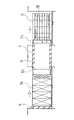
以下、図面について本発明の実施形態を詳細に説明する。図1〜図9は本発明の地下構造物の施工法の1実施形態を示す各工程の縦断側面図、図10〜図18は同上縦断正面図で、前記従来例を示す図19〜図22と同一構成要素には同一参照符号を付したものである。 Hereinafter, embodiments of the present invention will be described in detail with reference to the drawings. 1 to 9 are longitudinal side views of respective steps showing one embodiment of the construction method of an underground structure of the present invention, and FIGS. 10 to 18 are longitudinal front views of the same, and FIGS. The same components are denoted by the same reference numerals.
第1工程として図1、図10に示すように鉄道などの上部交通(図示は省略した)の脇に土留鋼矢板2を打設して、発進坑3と到達坑4を築造し、図2、図11に示すように前記発進坑3内に推進機を設置してこれで略正方形断面の箱形筒体である箱形ルーフ6を到達坑4に向けて圧入させる。箱形ルーフ6の上面には従来と同様にフリクションカッタープレート7を取り付けて、箱形ルーフ6とともに押し出す。
As a first step, as shown in FIGS. 1 and 10, the earth retaining
箱形ルーフ6は図23に示すように、略正方形断面の箱形筒体であり、鉤状の継手6a,6bを側部長手方向に連続して形成し、また、一面に平板からなるフリクションカッタープレート7を取り付けている。箱形ルーフ6は長さ方向に順次接続して必要長を埋設することができ、さらに鉤状の継手6a,6bを介して縦横方向に連続しながら並列させ組み配置する。
As shown in FIG. 23, the box-
箱形ルーフ6の配置は図11に示すように推進させようとするコンクリート函体9の外形に対応するように矩形配置αに行う他に、かかる矩形配置αの中を縦に仕切るように仕切配置βを行って地山25を小さな矩形(A)(B)(C)に分割するようにした。
As shown in FIG. 11, the box-
箱形ルーフ6は図24に示すように、略正方形断面の箱形筒体であり、平板状の継手6a,6bを長手方向に連続して形成し、また、平板からなるフリクションカッタープレート7を取り付けている。箱形ルーフ6は長さ方向に順次接続して必要長を埋設することができ、さらに平板状の継手6a,6bを重合わせて縦横方向に連続しながら並列させる。
As shown in FIG. 24, the box-
前記仕切配置βを行う箱形ルーフ6は縦方向に2列を並べるが、これらについてはフリクションカッタープレート7の取付は不要である。
Although the box-shaped
また、縦方向に2列を並べる場合において隣り合う配列同士の箱形ルーフ6は継手6a,6bによる接合は不要である。
Further, when two rows are arranged in the vertical direction, the box-shaped
箱形ルーフ6で囲まれた切羽部には土留部材19を配設し、この分割された地山25を箱形ルーフ6と一緒に押し出す。
A retaining
この土留部材19は土留鋼矢板2は鏡開きして箱形ルーフ6で囲まれた内方の鋼矢板を利用することができる。図中17は腹起こし材、20は発進台、21は到達台を示し、腹起こし材17で土留部材19を固定すればタイロット材で固定は必須ではない。
The
次に第3工程の図3に示すようにコンクリート函体9を発進坑3に設置し、コンクリート函体9の後方の反力壁8との間に推進設備として元押しジャッキ10、ストラット16を配設する。
Next, as shown in FIG. 3 of the third step, the
そして、止め部材(図示せず)でフリクションカッタープレート7を発進坑3側に固定する。このフリクションカッタープレート7により箱形ルーフ6およびコンクリート函体9と周辺土砂との縁切りを行う。
And the
次に先行して押出した箱形ルーフ6の後端部とコンクリート函体9の先端部とに鋼材を枠組んだ押角22をそれぞれ設置し、この押角22、22間に中押しジャッキ23を適宜間隔で配置する。
Next, a pushing
また、押角22、22の外周は鋼板によるカラー24で囲繞する。
Moreover, the outer periphery of the pushing
図4に示すようにコンクリート函体9を反力体として、中押しジャッキ23を伸長して押角22と組み配置した箱形ルーフ6を押し出す。
As shown in FIG. 4, with the
箱形ルーフ6を押し出すときに同時に箱形ルーフ6で囲まれた部分の地山25(小さな矩形(A)(B)(C)に分割された)も同時に押し出す。この場合、前記のようにフリクションカッタープレート7により箱形ルーフ6と周辺土砂との縁切りがなされているから、組み配置した箱形ルーフ6はスムーズに推進する。
At the same time when the box-shaped
次に図5に示すように伸長した中押しジャッキ23をフリーとし、元押しジャッキ10を伸長してコンクリート函体9と押角22を前方に押し出す。
Next, as shown in FIG. 5, the extended
このようにして組み配置した箱形ルーフ6および地山25の押し出しとコンクリート函体9の押し出しを交互に繰り返して、図7に示すように箱形ルーフ6とこの箱形ルーフ6に囲まれて同時に押出された地山25が到達坑4に到達したならば、到達坑4で箱形ルーフ6を撤去すると同時に、地山25を掘削して排土する。
As shown in FIG. 7, the box-shaped
なお、コンクリート函体9が地中を推進する時もその外周はフリクションカッタープレート7により箱形ルーフ6と周辺土砂との縁切りがなされているからスムーズに推進する。
Even when the
そして、さらにコンクリート函体9の先端が到達坑4に達するまで推進してコンクリート函体9の全長の推進が完了する。
Further, the
以上の実施形態は組み配置した箱形ルーフ6および内部の土砂24の中押しジャッキ23での押し出しはコンクリート函体9の推進とは個別に行うこととしたが、組み配置した箱形ルーフ6および内部の地山25の中押しジャッキ23での押し出しは、コンクリート函体9の推進と同時に行うようにしてもよい。
In the above-described embodiment, the
この場合、箱形ルーフ6および内部の地山25の押し出しは中押しジャッキ23と元押しジャッキ10の両方で行うことになる。
In this case, the
また、コンクリート函体9の推進は元押しジャッキ10での押し出しとしたが、到達坑側に設置した牽引設備で発進坑側から到達坑側に向けてコンクリート函体9を引っ張る牽引方式もある。
Further, although the
この牽引方式は、到達坑4側に地山による反力体を設け、この反力体の前方をさらに掘削して立坑を築造し、この立坑内に反力杭として反力壁を設ける。
In this traction system, a reaction force body by a natural ground is provided on the reaching
そして、発進坑3の発進台20にセットしたコンクリート函体9の後部に牽引ジャッキを取り付け、この牽引ジャッキに一端を取り付けた牽引ケーブルの他端を、反力壁に固定した定着装置に定着する。
Then, a traction jack is attached to the rear portion of the
このようにして牽引ジャッキを作動して牽引ケーブルでコンクリート函体9を発進坑3から到達坑4に向けて牽引する。
In this way, the traction jack is operated to pull the
前記実施形態は箱形ルーフ6を押し出すときに同時に箱形ルーフ6で囲まれた部分の地山25(小さな矩形(A)(B)(C)に分割された)も同時に押し出す場合について、説明したがこれら小さな矩形(A)(B)(C)を一緒に押し出さずに分割推進させることも可能である。
In the above embodiment, the case where the ground mountain 25 (divided into small rectangles (A), (B), and (C)) surrounded by the box-shaped
その場合、前記押角22も大きな枠組みではなく、前記地山25の各小さな矩形(A)(B)(C)に対応した小さな枠組みを並べたものとする。
In this case, the
押角22、22間に配置する中押しジャッキ23も各押角22、22を個別に押せるように数および位置を決定する。
The number and position of the
このようにしてコンクリート函体9を反力体として、中押しジャッキ23を伸長して押角22と組み配置した箱形ルーフ6を個別に順次押し出す。
In this way, using the
箱形ルーフ6を押し出すときに同時に箱形ルーフ6で囲まれた部分の地山25(小さな矩形(A)(B)(C)に分割された)も順次に押し出す。
At the same time when the box-shaped
1 上部交通 2 土留鋼矢板
3 発進坑 4 到達坑
5 推進機 6 箱形ルーフ
6a,6b 鉤状の継手 7 フリクションカッタープレート
8 反力壁 9 コンクリート函体
10 元押しジャッキ 11 刃口
12 小ジャッキ 13 支持材
14 止め部材 15 受台
16 ストラット 17 腹起こし材
18 タイロット材 19 土留部材
20 発進台 21 到達台
22 押角 23 中押しジャッキ
24 カラー 25 地山
DESCRIPTION OF SYMBOLS 1
Claims (3)
Priority Applications (1)
| Application Number | Priority Date | Filing Date | Title |
|---|---|---|---|
| JP2015172672A JP6139613B2 (en) | 2015-09-02 | 2015-09-02 | Construction method for underground structures |
Applications Claiming Priority (1)
| Application Number | Priority Date | Filing Date | Title |
|---|---|---|---|
| JP2015172672A JP6139613B2 (en) | 2015-09-02 | 2015-09-02 | Construction method for underground structures |
Publications (2)
| Publication Number | Publication Date |
|---|---|
| JP2017048605A JP2017048605A (en) | 2017-03-09 |
| JP6139613B2 true JP6139613B2 (en) | 2017-05-31 |
Family
ID=58279201
Family Applications (1)
| Application Number | Title | Priority Date | Filing Date |
|---|---|---|---|
| JP2015172672A Active JP6139613B2 (en) | 2015-09-02 | 2015-09-02 | Construction method for underground structures |
Country Status (1)
| Country | Link |
|---|---|
| JP (1) | JP6139613B2 (en) |
Families Citing this family (1)
| Publication number | Priority date | Publication date | Assignee | Title |
|---|---|---|---|---|
| JP7157193B2 (en) * | 2021-03-01 | 2022-10-19 | 誠 植村 | Box-shaped roof and box-shaped roof construction method using it |
Family Cites Families (8)
| Publication number | Priority date | Publication date | Assignee | Title |
|---|---|---|---|---|
| JPS63261097A (en) * | 1987-04-14 | 1988-10-27 | 株式会社奥村組 | Pipe for pipe roof and method of burying underground structure by said pipe |
| JP2587312B2 (en) * | 1990-06-29 | 1997-03-05 | 厚一 植村 | Underground structure installation method |
| JP2541846Y2 (en) * | 1991-07-17 | 1997-07-23 | 厚一 植村 | Concrete box for underground structure |
| JP3806098B2 (en) * | 2003-04-08 | 2006-08-09 | 誠 植村 | Blade structure of underground structure |
| JP4349570B2 (en) * | 2004-01-14 | 2009-10-21 | 大成建設株式会社 | Construction method of division box and underground level crossing |
| JP4319064B2 (en) * | 2004-02-25 | 2009-08-26 | 大成建設株式会社 | Construction method of split box and large section tunnel |
| JP3887383B2 (en) * | 2004-06-04 | 2007-02-28 | 誠 植村 | Construction method for underground structures |
| JP5363904B2 (en) * | 2009-08-04 | 2013-12-11 | ジャパントンネルシステムズ株式会社 | Middle push device |
-
2015
- 2015-09-02 JP JP2015172672A patent/JP6139613B2/en active Active
Also Published As
| Publication number | Publication date |
|---|---|
| JP2017048605A (en) | 2017-03-09 |
Similar Documents
| Publication | Publication Date | Title |
|---|---|---|
| JP4317843B2 (en) | Construction method for underground structures | |
| JP2008223397A (en) | Construction method for underground structure | |
| JP6139613B2 (en) | Construction method for underground structures | |
| JP6113778B2 (en) | Construction method for underground structures | |
| JP6212087B2 (en) | Construction method for underground structures | |
| JP6510620B1 (en) | Construction method of underground structure and push-in jack used therefor | |
| JP2008095386A (en) | Box roof used in method of constructing underground structure | |
| JP4134089B2 (en) | Construction method for underground structures | |
| JP6445478B2 (en) | Construction method for underground structures | |
| JP3887383B2 (en) | Construction method for underground structures | |
| CN108979641B (en) | Construction method for underground structure | |
| JP6982603B2 (en) | Box-shaped roof construction method | |
| JP5054164B2 (en) | Construction method for underground structures | |
| JP6714060B2 (en) | Construction method of underground structure | |
| JP2016223262A (en) | Removal method of existing structure | |
| JP6510432B2 (en) | Construction method of underground structure | |
| JP2018150780A (en) | Construction method of underground structure | |
| JP6441871B2 (en) | Box roof deflection reduction method for box roof method | |
| JP6081512B2 (en) | Construction method for underground structures | |
| JP6908666B2 (en) | Construction method of underground structure | |
| JP5342571B2 (en) | How to build an underpass | |
| JP5976728B2 (en) | Widening method for existing structures | |
| JPH09287389A (en) | Constructing method of subsurface structure | |
| JP6510690B1 (en) | Construction method of underground structure | |
| JP5037997B2 (en) | Leading beam construction method and leading beam connection structure |
Legal Events
| Date | Code | Title | Description |
|---|---|---|---|
| TRDD | Decision of grant or rejection written | ||
| A01 | Written decision to grant a patent or to grant a registration (utility model) |
Free format text: JAPANESE INTERMEDIATE CODE: A01 Effective date: 20170425 |
|
| A61 | First payment of annual fees (during grant procedure) |
Free format text: JAPANESE INTERMEDIATE CODE: A61 Effective date: 20170427 |
|
| R150 | Certificate of patent or registration of utility model |
Ref document number: 6139613 Country of ref document: JP Free format text: JAPANESE INTERMEDIATE CODE: R150 |
|
| R250 | Receipt of annual fees |
Free format text: JAPANESE INTERMEDIATE CODE: R250 |
|
| R250 | Receipt of annual fees |
Free format text: JAPANESE INTERMEDIATE CODE: R250 |
|
| R250 | Receipt of annual fees |
Free format text: JAPANESE INTERMEDIATE CODE: R250 |
|
| R250 | Receipt of annual fees |
Free format text: JAPANESE INTERMEDIATE CODE: R250 |
|
| R250 | Receipt of annual fees |
Free format text: JAPANESE INTERMEDIATE CODE: R250 |